KR101261783B1 - Apparatus for adjusting the height - Google Patents
Apparatus for adjusting the height Download PDFInfo
- Publication number
- KR101261783B1 KR101261783B1 KR1020130003193A KR20130003193A KR101261783B1 KR 101261783 B1 KR101261783 B1 KR 101261783B1 KR 1020130003193 A KR1020130003193 A KR 1020130003193A KR 20130003193 A KR20130003193 A KR 20130003193A KR 101261783 B1 KR101261783 B1 KR 101261783B1
- Authority
- KR
- South Korea
- Prior art keywords
- pole
- height adjustment
- locking
- inner tube
- cap
- Prior art date
- Legal status (The legal status is an assumption and is not a legal conclusion. Google has not performed a legal analysis and makes no representation as to the accuracy of the status listed.)
- Active
Links
- 230000006835 compression Effects 0.000 claims abstract description 23
- 238000007906 compression Methods 0.000 claims abstract description 23
- 230000008602 contraction Effects 0.000 claims abstract description 8
- 238000003780 insertion Methods 0.000 claims description 7
- 230000037431 insertion Effects 0.000 claims description 7
- 230000035939 shock Effects 0.000 claims description 4
- 238000000034 method Methods 0.000 claims 11
- 230000000149 penetrating effect Effects 0.000 claims 1
- 230000009194 climbing Effects 0.000 description 13
- 210000002414 leg Anatomy 0.000 description 4
- 230000000694 effects Effects 0.000 description 2
- 241001503987 Clematis vitalba Species 0.000 description 1
- 230000004308 accommodation Effects 0.000 description 1
- 230000008878 coupling Effects 0.000 description 1
- 238000010168 coupling process Methods 0.000 description 1
- 238000005859 coupling reaction Methods 0.000 description 1
- 210000002310 elbow joint Anatomy 0.000 description 1
- 238000005516 engineering process Methods 0.000 description 1
- 210000003127 knee Anatomy 0.000 description 1
Images




Classifications
-
- A—HUMAN NECESSITIES
- A01—AGRICULTURE; FORESTRY; ANIMAL HUSBANDRY; HUNTING; TRAPPING; FISHING
- A01M—CATCHING, TRAPPING OR SCARING OF ANIMALS; APPARATUS FOR THE DESTRUCTION OF NOXIOUS ANIMALS OR NOXIOUS PLANTS
- A01M3/00—Manual implements, other than sprayers or powder distributors, for catching or killing insects, e.g. butterfly nets
- A01M3/04—Manual implements, other than sprayers or powder distributors, for catching or killing insects, e.g. butterfly nets with adhesive surfaces
-
- A—HUMAN NECESSITIES
- A01—AGRICULTURE; FORESTRY; ANIMAL HUSBANDRY; HUNTING; TRAPPING; FISHING
- A01M—CATCHING, TRAPPING OR SCARING OF ANIMALS; APPARATUS FOR THE DESTRUCTION OF NOXIOUS ANIMALS OR NOXIOUS PLANTS
- A01M3/00—Manual implements, other than sprayers or powder distributors, for catching or killing insects, e.g. butterfly nets
- A01M3/02—Fly-swatters
-
- A—HUMAN NECESSITIES
- A01—AGRICULTURE; FORESTRY; ANIMAL HUSBANDRY; HUNTING; TRAPPING; FISHING
- A01M—CATCHING, TRAPPING OR SCARING OF ANIMALS; APPARATUS FOR THE DESTRUCTION OF NOXIOUS ANIMALS OR NOXIOUS PLANTS
- A01M2200/00—Kind of animal
- A01M2200/01—Insects
- A01M2200/012—Flying insects
Landscapes
- Life Sciences & Earth Sciences (AREA)
- Pest Control & Pesticides (AREA)
- Engineering & Computer Science (AREA)
- Insects & Arthropods (AREA)
- Wood Science & Technology (AREA)
- Zoology (AREA)
- Environmental Sciences (AREA)
- Mutual Connection Of Rods And Tubes (AREA)
Abstract
본 발명은 상단에 설치된 스틱캡과, 상기 스틱캡에 연결 설치되어 높낮이 조절을 가능케하는 조절레버와, 상기 스틱캡의 하부와 연결된 메인폴대와, 상기 메인폴대의 내·외로 인·출입되는 1·2차 신장폴대를 포함하는 높낮이 조절 장치에 관한 것으로, 상기 메인폴대는, 내부에 내측관과 외측관이 함께 설치되고, 상기 외측관의 외주면을 따라 높낮이 조절용 압축스프링이 설치되며, 상기 1차 신장폴대는, 상기 압축스프링의 신축에 의하여 상기 내측관의 내외로 인·출입되고, 길이 방향을 따라 복수 개의 걸림홈이 형성된 이동샤프트가 내부에 설치되되, 상기 내측관은, 볼이 장착된 잠금키가 하단에 연결 설치되고, 상기 볼이 상기 걸림홈에 걸림되어 상기 이동샤프트를 고정하며, 상기 조절레버의 작동에 의하여 상기 외측관이 상·하 이동함에 따라 상기 잠금키의 상기 이동샤프트에 대한 잠금과 해제가 발생하는 것을 특징으로 하는 높낮이 조절 장치를 제공한다.
본 발명에 의하면, 볼이 장착된 잠금키의 잠금과 해제를 통하여 원하는 만큼 높낮이의 신축과 고정이 자유롭게 조절될 수 있고, 사용 중 풀림이 방지되어 그 조절 상태를 계속 유지하도록 할 수 있으며, 보관시 조절레버가 임의대로 눌러지는 것을 방지할 수 있고, 신체의 하중도 충분히 지지할 수 있음은 물론, 조절스프링과 쇽업스프링까지 설치되어 높낮이 조절이 더욱 원활할 뿐만 아니라 부드럽고 유연하게 작동 가능한 효과가 있다.The present invention is a stick cap installed on the top, the control lever is connected to the stick cap is installed to enable height adjustment, the main pole pole connected to the lower portion of the stick cap, and the in and out of the main pole pole It relates to a height adjustment device including a secondary extension pole, the main pole, the inner tube and the outer tube is installed together, the height adjustment compression spring is installed along the outer circumferential surface of the outer tube, the primary extension The pole is drawn in and out of the inner tube by expansion and contraction of the compression spring, and a moving shaft having a plurality of locking grooves formed along a longitudinal direction is installed therein, wherein the inner tube has a ball-locked lock key. Is connected to the lower end, the ball is caught in the locking groove to fix the moving shaft, and the outer tube is moved up and down by the operation of the control lever Provides an elevator apparatus characterized in that locking it occurs and release for the mobile shaft of the locking key.
According to the present invention, through the locking and unlocking of the ball-mounted locking key can be adjusted freely to the height and extension of the height as desired, to prevent the loosening during use to maintain the adjustment state, when storing The control lever can be prevented from being pressed arbitrarily, and the body's load can be sufficiently supported, as well as the adjustment spring and the shock-up spring, so that the height adjustment is smoother and more flexible.
Description
본 발명은 높낮이 조절 장치에 관한 것으로, 보다 상세하게는 등산용 스틱, 자전거 안장, 책상 다리 등의 높낮이를 조절하기 위하여 길이의 신축과 고정이 자유롭게 조절될 수 있어 편리한 높낮이 조절 장치에 관한 것이다.
The present invention relates to a height adjustment device, and more particularly to a convenient height adjustment device that can be freely adjusted to stretch and fix the length to adjust the height of the climbing stick, bicycle saddle, desk legs and the like.
일반적으로 등산용 스틱, 자전거 안장, 책상 다리 등은 높낮이를 조절할 수 있게 설계되어 있다.In general, climbing sticks, bicycle saddles, desk legs are designed to adjust the height.
예컨대, 등산은 산에 오르는 것으로 심신을 단련하고 즐거움을 찾는 행위를 말하고, 현재는 레저나 스포츠로 이용하거나 미지의 세계에 대한 도전도 겸하여 위험한 산을 등정하기도 하는데, 산을 오르거나 내릴 때 신체의 하중을 지지하거나 일률적인 지형을 갖지 못하는 산행시 신체 균형을 유지할 필요가 있어 최근에는 산행가들에게 있어 등산용 스틱이 필수적인 아이템으로 자리잡고 있으며, 그 수요는 점점 증가하고 있고, 다양한 기능을 갖춘 등산용 스틱이 출시되고 있다. Climbing, for example, refers to the act of climbing the mountain to strengthen minds and pleasures, and to use it as a leisure or sport, or to climb a dangerous mountain as a challenge to the unknown world. It is necessary to maintain the balance of the body when hiking to support loads or do not have uniform terrain. In recent years, climbing sticks have become an essential item for climbers, and the demand is increasing. It is being released.
이러한 등산용 스틱은 단순한 지팡이의 역할을 넘어 두 다리에만 의존하는 보행의 노동을 팔에 상당 부분 분담시킴으로써 사용자의 체력 소모를 줄이고 보행속도를 빠르고 안전하게 해 준다.These climbing sticks go beyond the role of a cane, and share a large portion of the walking labor that relies on only two legs on the arm, which reduces the user's physical consumption and speeds up the walking speed.
즉, 등산로의 고르지 못한 지형에서 사용자의 균형을 유지시켜 주고, 하산 시 무릎의 충격을 덜어주는 그야말로 안전산행의 일등 도우미인 것이다. 이때, 등산용 스틱의 길이는 이를 잡고 섰을 때 팔꿈치 관절의 각도는 90°도가 이상적이고, 경사로나 언덕을 오를 때에는 10~15㎝ 길게 사용하는 것이 좋으며, 여러 가지 상황에 따라 사용자의 체형에 맞게 높낮이를 조절하여 사용할 필요가 있다.In other words, to maintain the balance of the user in the uneven terrain of the hiking trails to reduce the impact of the knees in the ascent is really the first helper of safe hiking. At this time, the length of the climbing stick is ideal for the angle of the elbow joint is 90 ° when holding the stand, it is recommended to use a 10 ~ 15cm long when climbing the slope or hill, depending on the situation depending on the user's body type It needs to be adjusted and used.
등산용 스틱에 관한 종래의 기술로서 대한민국 등록실용신안공보 제20-0219048호가 도 1에 개시되어 있는 바, 그 구성은 스틱을 지칠시에 노상과 면접촉을 이루도록 함과 동시에 충격력을 흡수할 수 있도록 고무패드로서 최하측부에 구비되는 지침부(1)와, 상기 지침부(1)가 고정되는 하측폴대(2c)가 상측폴대(2a)에 삽입 또는 인출되어 조절됨과 동시에 조절 완료후에는 너트(2b)로서 조임 고정할수 있도록 구비되는 길이조절수단(2)과, 상기 상측폴대(2a)의 일측에 고정되는 손잡이(5)에 내설되어지고 일정부위 외측으로 돌출되어진 누름부(3a)의 접속유무에 따라 동작되는 경음기(3)와, 상기 상·하측폴대(2a,2c)를 둘러서 장식하게 되며 식별이 용이하도록 구비되는 야광띠(4)를 포함한다.As a conventional technology related to a stick for climbing, Korean Registered Utility Model Publication No. 20-0219048 is disclosed in FIG. 1, and its structure is designed to allow the stick to make a surface contact with the roadbed when worn out and to absorb the impact force. The
하지만, 종래의 등산용 스틱은 높낮이 조절시 많은 힘이 필요하여 조작이 매우 번거롭고, 여성이나 노약자는 물론이고 건장한 남성의 경우에도 쉽게 조작할 수 없으며, 시간도 많이 소요됨은 물론, 등산용 스틱의 높낮이를 사용자가 원하는 만큼만 신축시키고 이를 고정하는 것이 불편하여 사용성 및 편의성이 떨어지는 문제가 있다.However, the conventional climbing sticks require a lot of power to adjust the height, so the operation is very cumbersome, not only for women or the elderly, but also for the strong men, it is not easy to operate, it takes a lot of time, as well as the height of the climbing stick It is inconvenient to stretch and fix as much as you want, and there is a problem of poor usability and convenience.
또한, 종래의 상기 등산용 스틱을 사용할 경우 폴대가 단단히 조여지지 않아 사용 중에 쉽게 풀리게 되거나, 등산용 스틱을 접어서 휴대할 경우 스틱이 흔들리거나 충격을 받는 경우 폴대가 임의적으로 인출됨으로 인하여 그 조절 상태가 계속하여 유지되지 못하고, 신체의 하중도 충분히 지지하지 못하는 문제가 있다.
In addition, in the case of using the conventional climbing stick, the pole is not firmly tightened during use because it is not tightly tightened, or when carrying the folding stick, the stick is shaken or shocked when the pole is randomly drawn out, and thus the adjustment state continues. There is a problem that can not be maintained, not enough to support the load of the body.
본 발명은 상술된 문제들을 모두 해결하기 위하여 안출된 것으로, 볼에 의한 잠금과 해제를 통하여 원하는 만큼의 높낮이의 신축과 고정이 자유롭게 조절될 수 있고, 사용 중 풀림이 방지되어 그 조절 상태를 계속 유지하도록 할 수 있으며, 보관시 조절레버가 임의대로 눌러지는 것을 방지할 수 있고, 신체의 하중도 충분히 지지할 수 있음은 물론, 조절스프링과 쇽업스프링까지 설치되어 높낮이 조절이 더욱 원활할 뿐만 아니라 부드럽고 유연하게 작동 가능한 높낮이 조절 장치의 제공을 그 목적으로 한다.The present invention has been made to solve all the above-described problems, and can be freely adjusted and stretched as much as desired through the locking and releasing by the ball, the loosening is prevented during use to maintain the adjustment state It can prevent the control lever from being pressed arbitrarily during storage, and it can support the load of the body as well as the adjustment spring and the shock up spring, so that the height adjustment is not only smoother but also soft and flexible. It is an object of the present invention to provide a height adjusting device which can be operated easily.
또한, 조절레버의 단순 회전 조작만으로 압축스프링의 힘을 이용하여 장치의 높낮이를 용이하게 가변시킬 수 있고, 장치를 원하는 만큼만 신축시킨 후 잠금키로 쉽게 고정할 수 있어 편리하므로, 오르막길 및 내리막길 등 여러 가지 사용환경 속에서 신속히 대응하여 조작 가능하여 우수한 사용성 및 편의성을 갖는 높낮이 조절 장치의 제공에도 그 목적이 있다.In addition, the height of the device can be easily changed using the force of the compression spring only by the simple rotation of the control lever. It is also an object of the present invention to provide a height adjusting device that can be quickly and manipulated in various usage environments and has excellent usability and convenience.
더불어, 테이퍼진 형상을 갖는 조절너트의 잠금 또는 개방과, 고정레버의 회동 및 고정스프링의 탄성 등을 이용하여 폴대를 고정 또는 해제함으로써 지지력이 우수함은 물론 조작도 편리한 높낮이 조절 장치의 제공에도 그 목적이 있다.
In addition, the locking and opening of the adjustment nut having a tapered shape, the rotation of the fixed lever and the elasticity of the fixed spring to fix or release the pole, thereby providing a height adjustment device that is excellent in supporting power and convenient to operate. There is this.
상기 과제를 해결하기 위하여 본 발명은 상단에 설치된 스틱캡과, 상기 스틱캡에 연결 설치되어 높낮이 조절을 가능케하는 조절레버와, 상기 스틱캡의 하부와 연결된 메인폴대와, 상기 메인폴대의 내·외로 인·출입되는 1·2차 신장폴대를 포함하는 높낮이 조절 장치에 있어서, 상기 메인폴대는, 내부에 내측관과 외측관이 함께 설치되고, 상기 외측관의 외주면을 따라 높낮이 조절용 압축스프링이 설치되며, 상기 1차 신장폴대는, 상기 압축스프링의 신축에 의하여 상기 내측관의 내외로 인·출입되고, 길이 방향을 따라 복수 개의 걸림홈이 형성된 이동샤프트가 내부에 설치되되, 상기 내측관은, 볼이 장착된 잠금키가 하단에 연결 설치되고, 상기 볼이 상기 걸림홈에 걸림되어 상기 이동샤프트를 고정하며, 상기 조절레버의 작동에 의하여 상기 외측관이 상·하 이동함에 따라 상기 잠금키의 상기 이동샤프트에 대한 잠금과 해제가 발생하는 것을 특징으로 하는 높낮이 조절 장치를 제공한다.In order to solve the above problems, the present invention provides a stick cap installed at an upper end, an adjustment lever connected to the stick cap to enable height adjustment, a main pole pole connected to a lower portion of the stick cap, and an inside / outside of the main pole pole. In the height adjustment device comprising a primary and secondary extension pole to be pulled in and out, the main pole pole, the inner tube and the outer tube is installed together inside, the height adjustment compression spring is installed along the outer circumferential surface of the outer tube The primary extension pole is drawn in and out of the inner tube by expansion and contraction of the compression spring, and a moving shaft having a plurality of locking grooves formed along a longitudinal direction is installed therein, wherein the inner tube is a ball. The mounted locking key is connected to the lower end, the ball is caught in the locking groove to fix the moving shaft, the outer tube by the operation of the control lever It is provided with a height adjustment device characterized in that the locking and unlocking of the locking shaft with respect to the moving shaft as the up and down movement.
이때, 상기 스틱캡은, 몸체를 이루고 내부에 수용공간을 갖는 캡홀더, 상기 캡홀더의 일측에 관통 형성된 개방공, 상기 조절레버가 회전 가능하도록 상기 개방공에 설치된 힌지핀, 상기 개방공 상측에 외측으로 돌출되어 상기 조절레버를 지지하는 지지환, 및 상기 캡홀더 중간에 관통 형성되어 상기 내측관을 고정하는 고정핀이 삽입되는 삽입공을 포함하는 것에도 그 특징이 있다.At this time, the stick cap, the cap holder having a receiving space therein, the opening hole formed through the one side of the cap holder, the hinge pin installed in the opening hole so that the control lever is rotatable, the upper side of the opening hole It also features a support ring protruding outward to support the control lever, and the insertion hole is formed in the middle of the cap holder penetrated to secure the inner tube is inserted.
게다가, 상기 조절레버는, 상기 지지환과 접하도록 설치된 지지편, 연결핀에 의해 상기 지지편과 연결되어 회동 가능하도록 설치된 조절편, 상기 힌지핀이 관통 결합되는 힌지공, 및 상기 스틱캡의 내부 수용공간으로 삽입되고 상기 조절편의 조작에 의해 상기 외측관을 상·하로 이동시키는 이동편을 포함하는 것에도 그 특징이 있다.In addition, the control lever, the support piece is installed in contact with the support ring, the control piece is installed to be rotatable connected to the support piece by a connecting pin, the hinge hole through which the hinge pin is coupled, and the inner housing of the stick cap It is also characterized by including a moving piece which is inserted into the space and moves the outer tube up and down by the operation of the adjusting piece.
뿐만 아니라, 상기 스틱캡의 하부에 상기 내측관 및 외측관의 일부가 수용되고, 상기 스틱캡의 상부에 조절스프링이 상기 외측관의 상단과 연결되도록 설치된 것에도 그 특징이 있다.In addition, a portion of the inner tube and the outer tube is accommodated in the lower portion of the stick cap, it is characterized in that the adjustment spring is installed to be connected to the upper end of the outer tube on the top of the stick cap.
더불어, 상기 메인폴대는, 상기 1·2차 신장폴대가 함께 내재 수용되되, 상기 1차 신장폴대의 이동샤프트가 이동하는 통로가 되는 내측관, 상기 조절레버의 작동에 의하여 상·하 방향으로 이동 가능하도록 상기 내측관의 외측에 설치된 외측관, 상기 외측관의 외주면을 따라 설치된 높낮이 조절용 압축스프링, 및 하단에 상기 압축스프링의 신축에 의하여 상기 메인폴대의 내주면을 따라 이동하면서 상기 1차 신장폴대를 가압하는 이동피스톤을 포함하는 것에도 그 특징이 있다.In addition, the main pole, the primary and secondary extension poles are accommodated together, the inner tube is a passage for moving the movement shaft of the primary extension pole, the movement in the vertical direction by the operation of the control lever. The primary expansion pole while moving along the inner circumferential surface of the main pole by the outer tube installed on the outside of the inner tube, the height adjustment compression spring installed along the outer circumferential surface of the outer tube, and the expansion and contraction of the compression spring at the bottom It is also characterized by including a moving piston to pressurize.
이와 함께, 상기 메인폴대는, 상기 내측관의 하단에 상기 이동샤프트를 고정하는 잠금키가 연결 설치되고, 상기 조절레버의 작동에 의하여 상기 외측관이 상하로 이동함에 따라 상기 잠금키의 상기 이동샤프트에 대한 잠금과 해제가 발생하는 것에도 그 특징이 있다.In addition, the main pole, the locking key for fixing the movable shaft is installed in the lower end of the inner tube, the movement shaft of the locking key as the outer tube moves up and down by the operation of the control lever. This is also true for locking and unlocking.
그리고, 상기 외측관은 상단 양측에 길이 방향으로 장공이 관통 형성되고, 상기 장공에 상기 조절레버의 일부가 삽입되어 상기 외측관을 상·하로 이동가능케 하는 것에도 그 특징이 있다.In addition, the outer tube is characterized in that the through-hole is formed in the longitudinal direction on both sides of the upper end, a portion of the control lever is inserted into the long hole to enable the outer tube to move up and down.
또한, 상기 내측관은 상단에 단공이 관통 형성되고, 상기 삽입공을 통과한 고정핀이 상기 단공에 결합되어 상기 내측관을 고정하는 것에도 그 특징이 있다.In addition, the inner tube is characterized in that a short hole is formed through the upper end, the fixing pin passing through the insertion hole is coupled to the short hole to fix the inner tube.
나아가, 상기 잠금키는 하부에 복수 개의 잠금척이 형성되고, 상기 잠금척의 내측에는 잠금홀이 형성되며, 상기 잠금홀에 볼이 이동 가능하도록 장착되어 있는 것에도 그 특징이 있다.Furthermore, the locking key has a plurality of lock chucks are formed at the bottom, a lock hole is formed inside the lock chuck, it is also characterized in that the ball is mounted in the lock hole to be movable.
아울러, 상기 1차 신장폴대는 내·외관의 2중관으로 이루어지되, 상기 이동피스톤과 접촉 연결되어 상기 1차 신장폴대의 이동을 가이드하는 가이드홀더, 상기 가이드홀더의 내측에 위치한 상기 내관의 외주면 상단에 설치된 쇽업스프링, 및 상기 내관의 내부에 설치되고, 하단이 외측으로 확장되어 상기 내관에 고정 결합되며, 상기 이동피스톤의 이동에 따라 함께 이동하는 이동샤프트;를 포함하는 것에도 그 특징이 있다.In addition, the primary extension pole is made of a double pipe of the inner, outer shell, the guide holder is connected to the moving piston to guide the movement of the primary extension pole, the upper end of the outer circumference of the inner tube located inside the guide holder It is also characterized in that it includes a shock-up spring installed in, and installed inside the inner tube, the lower end is extended to the outside and fixedly coupled to the inner tube, the moving shaft moves together with the movement of the moving piston.
여기서, 상기 메인폴대는 하단에 제1폴캡이 결합되고, 상기 제1폴캡의 외측에 하부가 하측으로 테이퍼지도록 형성된 조절너트가 회전 가능하도록 연결되어 가압에 의하여 인출된 상기 1차 신장폴대를 조임 고정하는 것에도 그 특징이 있다.Here, the main pole pole is coupled to the first pole cap at the lower end, the adjustment nut is formed so that the lower side is tapered downward to the outer side of the first pole cap is rotatably connected to tighten the primary extension pole pulled out by pressing It also has its features.
한편, 상기 1차 신장폴대의 하단에 제2폴캡이 결합되고, 상기 제2폴캡에 고정레버가 회동나사에 의해 회동 가능하도록 결합되며, 상기 고정레버는 상단에 고정스프링이 설치되고, 하단에 상기 2차 신장폴대에 형성된 고정홈에 착탈가능하도록 체결되는 누름편이 형성되어 있는 것에도 그 특징이 있다.
On the other hand, the second pole cap is coupled to the lower end of the primary extension pole, the fixing lever is coupled to the second pole cap to be rotatable by the rotation screw, the fixing lever is installed on the upper fixed spring, the lower end It is also characterized in that the pressing piece is detachably fastened to the fixing groove formed in the secondary extension pole.
본 발명에 의하면, 볼에 의한 잠금과 해제를 통하여 원하는 만큼 높낮이의 신축과 고정이 자유롭게 조절될 수 있고, 사용 중 풀림이 방지되어 그 조절 상태를 계속 유지하도록 할 수 있으며, 보관시 조절레버가 임의대로 눌러지는 것을 방지할 수 있고, 신체의 하중도 충분히 지지할 수 있음은 물론, 조절스프링과 쇽업스프링까지 설치되어 높낮이 조절이 더욱 원활할 뿐만 아니라 부드럽고 유연하게 작동 가능한 효과가 있다.According to the present invention, through the locking and releasing by the ball can be freely adjusted and stretched as high as desired, can be prevented loosening during use to keep the adjustment state, the storage lever is optional when storing It can be prevented from being pressed as well, and can sufficiently support the load of the body, as well as the adjustment spring and the shock-up spring, so that the height adjustment is not only smoother but also smooth and flexible.
또한, 조절레버의 단순 회전 조작만으로 압축스프링의 힘을 이용하여 높낮이를 용이하게 가변시킬 수 있고, 스틱을 원하는 만큼만 신축시킨 후 잠금키로 쉽게 고정할 수 있어 편리하므로, 오르막길 및 내리막길 등 여러 가지 사용환경 속에서 신속히 대응하여 조작 가능하여 우수한 사용성 및 편의성을 갖는 효과가 있다.In addition, by simply rotating the control lever, the height can be easily changed by using the force of the compression spring, and it can be easily fixed with the lock key after stretching the stick as much as you want. It can be quickly responded to the operation in the environment has the effect of having excellent usability and convenience.
더불어, 테이퍼진 형상을 갖는 조절너트의 잠금 또는 개방과, 고정레버의 회동 및 고정스프링의 탄성 등을 이용하여 폴대를 고정 또는 해제함으로써 지지력이 우수함은 물론 조작도 편리한 효과가 있다.
In addition, by using the locking or opening of the adjustment nut having a tapered shape, the rotation of the fixing lever and the elasticity of the fixing spring, or the like, the pawl is fixed or released to provide excellent support and convenient operation.
도 1은 종래의 높낮이 조절 장치의 일례를 나타낸 사시도.
도 2는 본 발명에 따른 높낮이 조절 장치의 일부를 나타낸 단면도.
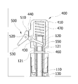
도 3은 본 발명에 따른 높낮이 조절 장치의 외관 사시도.
도 4a 내지 도 4d는 본 발명에 따른 주요 구성품을 나타낸 단면도로서, 도 4a는 조절레버, 도 4b는 스틱캡, 도 4c는 외측관, 도 4d는 내측관을 나타낸 단면도.
도 5a는 도 3의 "A" 부분의 상세 단면도.
도 5b는 도 3의 "B" 부분의 상세 단면도.
도 5c는 도 3의 "C" 부분의 상세 단면도.
도 6은 본 발명의 잠금키의 평단면도로서, 도 6(a)는 단속시 도면, 도 6(b)는 개방시 도면.
도 7은 본 발명의 고정레버에 의한 2차 신장폴대의 고정과 해제 작동을 나타낸 도면.
도 8(a) 및 도 8(b)는 본 발명의 높낮이 조절 장치의 높낮이 조절시 작동 상태를 나타낸 단면도.
도 9(a) 및 도 9(b)는 본 발명의 높낮이 조절 장치의 고정시 작동 상태를 나타낸 단면도.
도 10은 본 발명에 따른 높낮이 조절 장치의 신장 관계를 나타낸 외관의 도면으로서, 도 10a는 스틱을 접었을 때의 도면, 도 10b는 스틱의 신장시 도면.1 is a perspective view showing an example of a conventional height adjusting device.
Figure 2 is a sectional view showing a part of the height adjusting device according to the present invention.
Figure 3 is an external perspective view of the height adjusting device according to the present invention.
Figures 4a to 4d is a cross-sectional view showing the main components according to the present invention, Figure 4a is a control lever, Figure 4b is a stick cap, Figure 4c is an outer tube, Figure 4d is a cross-sectional view showing the inner tube.
5A is a detailed cross-sectional view of the portion “A” of FIG. 3.
5B is a detailed cross-sectional view of the portion “B” of FIG. 3.
5C is a detailed cross-sectional view of the portion “C” of FIG. 3.
Figure 6 is a plan sectional view of the locking key of the present invention, Figure 6 (a) is a view when interrupted, Figure 6 (b) is a view when opened.
7 is a view showing the fixing and release operation of the secondary extension pole by the fixing lever of the present invention.
Figure 8 (a) and Figure 8 (b) is a cross-sectional view showing the operating state of the height adjustment of the height adjustment device of the present invention.
Figure 9 (a) and Figure 9 (b) is a cross-sectional view showing an operating state when the height adjustment device of the present invention.
10 is a view of the appearance showing the elongation relationship of the height adjusting device according to the present invention, Figure 10a is a view when the stick is folded, Figure 10b is a view when the stick is stretched.
본 발명자는 종래의 높낮이 조절 장치를 사용할 경우 높낮이 조절시 많은 힘이 필요하여 조작이 매우 번거롭고, 여성이나 노약자는 물론이고 건장한 남성의 경우에도 쉽게 조작할 수 없으며, 시간도 많이 소요됨은 물론, 높낮이를 사용자가 원하는 만큼만 신축시키고 이를 고정하는 것이 불편하여 사용성 및 편의성이 떨어질 뿐만 아니라, 폴대가 단단히 조여지지 않아 사용 중에 쉽게 풀리게 되거나, 높낮이 조절 장치를 접어 휴대할 경우 스틱이 흔들리거나 충격을 받는 경우 폴대가 임의적으로 인출됨으로 인하여 그 조절 상태가 계속하여 유지되지 못하고, 신체의 하중도 충분히 지지하지 못하는 문제가 있음을 인지하였다.The present inventors require a lot of power to adjust the height when using the conventional height adjustment device, very cumbersome operation, not easy to operate even in the case of women or the elderly and healthy men, it takes a lot of time, of course, It is not convenient to stretch and fix as much as user wants, and it is not only usability and convenience. It has been recognized that there is a problem that the control state cannot be maintained continuously due to being drawn out arbitrarily, and the load of the body is not sufficiently supported.
본 발명자는 이를 해결하기 위하여 연구와 노력을 거듭한 결과, 볼에 의한 잠금과 해제를 통하여 원하는 만큼 높낮이의 신축과 고정이 자유롭게 조절될 수 있고, 사용 중 풀림이 방지되어 그 조절 상태를 계속 유지하도록 할 수 있으며, 보관시 조절레버가 임의대로 눌러지는 것을 방지할 수 있고, 신체의 하중도 충분히 지지할 수 있음은 물론, 조절스프링과 쇽업스프링까지 설치되어 높낮이 조절이 더욱 원활할 뿐만 아니라 부드럽고 유연하게 작동 가능하고, 또한, 조절레버의 단순 회전 조작만으로 압축스프링의 힘을 이용하여 높낮이를 용이하게 가변시킬 수 있고, 원하는 만큼만 신축시킨 후 잠금키로 쉽게 고정할 수 있어 편리하므로, 오르막길 및 내리막길 등 여러 가지 사용환경 속에서 신속히 대응하여 조작 가능하여 우수한 사용성 및 편의성을 가지며, 더불어, 테이퍼진 형상을 갖는 조절너트의 잠금 또는 개방과, 고정레버의 회동 및 고정스프링의 탄성 등을 이용하여 폴대를 고정 또는 해제함으로써 지지력이 우수함은 물론 조작도 편리한 높낮이 조절 장치에 관한 본 발명을 완성시켰다.As a result of repeated studies and efforts to solve this problem, the present inventors can freely adjust the height and extension of the height as desired through locking and releasing by the ball, and prevent loosening during use to maintain the adjustment state. It can prevent the control lever from being pressed arbitrarily during storage, and it can support the load of the body as well as the adjustment spring and the shock up spring, so that the height adjustment is not only smoother but also soft and flexible. It is also possible to easily change the height by using the force of the compression spring by simply rotating the control lever, and it can be easily fixed with the lock key after stretching as much as you want. It can be quickly responded to in various usage environments for excellent usability and convenience. In addition, by using the locking or opening of the adjustment nut having a tapered shape, the rotation of the fixed lever and the elasticity of the fixed spring, etc. to fix or release the pole pole, the bearing capacity is excellent and the operation is convenient. The invention was completed.
이하, 도면을 참조하여 본 발명에 대하여 실시예를 중심으로 상세히 설명한다.Hereinafter, the present invention will be described in detail with reference to the accompanying drawings.
본 발명에 따른 높낮이 조절 장치(S)는 조절레버의 작동에 의한 볼에 의한 잠금과 해제 작동을 통하여 원하는 만큼 높낮이의 신축과 고정이 자유롭게 조절될 수 있도록 구성된 것으로, 크게 메일폴대(100), 1차 신장폴대(200), 2차 신장폴대(300), 스틱캡(400) 및 조절레버(500)를 포함하여 이루어진다.Height adjustment device (S) according to the present invention is configured to be freely adjusted and stretched as much as desired through the locking and unlocking operation by the ball by the operation of the control lever, largely
도 2와 도 3을 참조하여 설명하면, 상기 메인폴대(100)는 1·2차 신장폴대(200, 300)가 함께 내재 수용되고, 내부에 설치된 내측관(110) 및 외측관(120)과, 상기 외측관(120)의 외주면을 따라 설치된 높낮이 조절용 압축스프링(130)을 포함하여 이루어지고, 더불어 상기 압축스프링(130)의 신축에 의하여 상기 1차 신장폴대를 가압하는 이동피스톤(140)과, 상기 메인폴대(100)를 상기 1차 신장폴대(200)와 고정 또는 해제하기 위한 제1폴캡(150) 및 조절너트(160)를 더 포함할 수 있다.Referring to Figures 2 and 3, the
이때, 상기 내측관(110)은 상기 1차 신장폴대(200)에 내설된 이동샤프트(250)가 이동하는 통로가 되는 것으로, 도 4d와 같이 상단에는 단공(112)이 형성되고, 상기 단공(112)에는 고정핀(113)이 관통 결합된다.At this time, the
또한, 도 6에 도시된 바와 같이, 상기 내측관(110)의 하단에는 상기 이동샤프트(250)를 고정하는 잠금키(111)가 연결 설치되고, 이때 상기 잠금키(111)는 그 하부에 복수 개의 잠금척(111a)이 형성되며, 바람직하게는 3개로 형성된다.In addition, as shown in Figure 6, the lower end of the
더불어, 상기 잠금척(111a)은 내측에 잠금홀(111b)이 형성되고, 상기 잠금홀(111b)에는 볼(111c)이 장착되며, 상기 볼(111c)이 상기 외측관(120)에 의해 가압되어 상기 이동샤프트(250)에 형성된 임의의 걸림홈(251)에 삽입되어 고정되어 있다가, 조절레버(500)을 눌러 잠금 해제시 상기 외측관(120)이 위로 당겨지게 되어 볼(111c)에 대한 가압이 해제되고, 이에 따라 이동샤프트(250)는 하측으로 이동하게 되며, 상기 이동샤프트(250)가 이동하면서 상기 볼(111c)을 상기 잠금홀(111b) 상에서 외측으로 밀어 내어 높낮이 조절 장치(S)의 높낮이가 신장될 수 있는 것이고, 상기 잠금키(111)에 구 형태를 갖는 볼(111c)을 장착하여 사용하기 때문에 상기 이동샤프트(250)의 이동이 원활하게 이루어지고 높낮이 조절 장치(S)의 내구성이 증가한다.In addition, the locking
상기 외측관(120)은 상기 내측관(110)의 외측에 설치되고, 상기 조절레버(500)의 작동에 의하여 상·하 방향으로 이동한다.The
여기서, 상기 외측관(120)은 도 4c와 같이 상단 양측에 장공(121)이 길이 방향을 따라 형성되고, 상기 장공(121)에 상기 조절레버(500)의 이동편(550)이 삽입되어 상기 외측관(120)을 상·하 방향으로 이동시키며, 이로써 상기 잠금키(111)의 상기 이동샤프트(250)에 대한 잠금과 해제가 발생하게 된다.Here, the
즉, 내측관(110)이 고정핀(113)에 고정된 상태에서, 상기 조절레버(500)의 이동편(550)이 상기 장공(121)의 공간으로 삽입된 후 장공(121)의 상단에 걸림되고, 이때 상기 조절레버(500)를 상·하로 조작하게 됨에 따라 상기 이동편(550)에 걸린 외측관(120)이 상·하로 이동 가능하는 것이다.That is, in the state in which the
더불어, 상기 압축스프링(130)은 상기 외측관(120)의 외주면을 따라 설치되어 신축됨으로써 상기 1차 신장폴대(200)가 메인폴대(100)로부터 인·출입이 가능하게 된다.In addition, the
또한, 상기 메인폴대(100)의 하단에는 상기 압축스프링(130)의 신축에 의하여 상기 메인폴대(100)의 내주면을 따라 이동하면서 상기 1차 신장폴대(200)를 가압하는 이동피스톤(140)이 설치된다.In addition, at the lower end of the
이와 함께, 도 5b에 도시된 바와 같이, 상기 메인폴대(100)는 하단에 제1폴캡(150)이 결합되고, 상기 제1폴캡(150)의 외측에 하부가 하측으로 테이퍼지도록 형성된 조절너트(160)가 회전 가능하도록 연결된다.In addition, as shown in Figure 5b, the
즉, 상기 조절레버(500)를 눌러 상기 잠금키(111)의 잠금을 해제하고, 상기 압축스프링(130)의 작용에 의하여 이동피스톤(140)를 가압 밀어내어 상기 1차 신장폴대(200)를 상기 메인폴대(100)로부터 인출시킨 후, 상기 조절너트(160)를 회전시킴으로써 상기 조절너트(160)가 상측으로 이동하게 되고, 이로써 상기 조절너트(160)가 가압하여, 인출된 상기 1차 신장폴대(200)를 조임 고정하는 것이다.That is, by pressing the
이때, 상기 조절너트(160)의 회전이 원활히 이루어지게 하기 위하여 상기 조절너트(160)의 내주면에는 나사산이 형성되고, 상기 제1폴캡(150)의 외주면에는 이에 대응되는 형상의 나사산이 형성될 수도 있다.In this case, in order to smoothly rotate the
상기 1차 신장폴대(200)는 상기 메인폴대(100)에 내재 수용되어 인·출입됨으로써 높낮이 조절 장치(S)의 높낮이가 신장 또는 축소되는 것으로, 내관(210)과 외관(220)의 2중관으로 이루어진다.The
또한, 상기 1차 신장폴대(200)는 상기 이동피스톤(140)의 턱진 하부와 접촉 연결되어 상기 1차 신장폴대(200)의 이동을 가이드하는 가이드홀더(230)가 구비되며, 상기 이동피스톤(140)의 하부 돌출면에 내관(210)이 연결되고, 상기 가이드홀더(230)의 하부에 상기 외관(220)이 연결되어, 상기 이동피스톤(140)의 상·하 이동에 따라 상기 1차 신장폴대(200)도 함께 이동하는 것이다.In addition, the
게다가, 상기 가이드홀더(230)의 내측에 위치한 상기 내관(210)의 외주면 상단에는 쇽업스프링(240)이 설치되고, 상기 쇽업스프링(240)은 조절레버(500)를 눌러 높낮이 조절 장치(S)의 높낮이를 조절할 때 상기 쇽업스프링(240)의 힘에 의하여 부드럽고 유연하게 높낮이 조절 장치(S)가 지면에 작용하게 할 수 있다.In addition, a shock-up
뿐만 아니라, 상기 내관(210)의 내부에는 길이 방향을 따라 이동샤프트(250)가 설치되고, 상기 이동샤프트(250)의 하단은 외측으로 확장되어 상기 내관(210)에 고정 결합되며, 상기 압축스프링(130)의 신축에 의해 상기 이동피스톤(140)이 상기 메인폴대(100)의 내주면을 이동함에 따라 함께 상·하로 이동하여 상기 1차 신장폴대(200)를 상기 메인폴대(100)의 내·외로 입출시킬 수 있다.In addition, the
이때, 상기 이동샤프트(250)는 외측으로 돌출 형성된 돌부와 내측으로 요입 형성된 홈부가 교번되어 반복 형성되고, 특히 홈부에는 걸림홈(251)이 형성되어, 상기 잠금척(111a)의 잠금홀(111b)에 장착된 볼(111c)이 상기 걸림홈(251)에 삽입되어 높낮이 조절 장치(S)의 높낮이가 더 이상 신장되거나 축소되는 것을 단속하는 것이다.At this time, the
그리고, 도 5c에 도시된 바와 같이, 상기 1차 신장폴대(200)의 하단에는 제2폴캡(260)이 결합되고, 상기 제2폴캡(260)에 고정레버(270)가 회동나사(271)에 의해 회동 가능하도록 결합되며, 여기서 상기 고정레버(270)는 상단에 고정스프링(280)이 설치되고, 하단에 상기 2차 신장폴대(300)에 형성된 고정홈(310)에 착탈가능하도록 체결되는 누름편(290)이 형성된다.And, as shown in Figure 5c, the
즉, 상기 1차 신장폴대(200)에 내재 수용되어 있는 2차 신장폴대(300)를 외측으로 잡아당겨 수동으로 인출시킨 후에, 도 7에 도시된 바와 같이 상기 고정레버(270)의 누름편(290)이 상기 고정홈(310)에 장착되도록 하고, 높낮이 조절 장치(S)를 접을 때에는 고정스프링(280)이 설치된 고정레버(270)의 부분을 누르면 상기 고정레버(270)의 누름편(290)이 고정홈(310)과 분리되어 나오게 되며, 이로써 2차 신장폴대(300)가 1차 신장폴대(200)의 내부로 삽입되어 접혀지는 것이다.That is, after pulling out the
그리고, 상기 2차 신장폴대(300)는 상기 1차 신장폴대(200)에 내재 수용되고, 하단에 지면과 접촉되는 스파이크가 형성되며, 상단에 고정홈(310)이 형성되고, 사용자에 의해 수동으로 인출된다.In addition, the
상기 스틱캡(400)은, 몸체를 이루는 캡홀더(410)가 내부에 수용공간(410a)을 갖도록 형성되고, 상기 캡홀더(410)의 일측에는 개방공(420)이 관통 형성되며, 상기 개방공(420)에는 힌지핀(430)이 설치되어 상기 조절레버(500)가 회전 가능하도록 구비된다.The
또한, 상기 개방공(420)의 상측에는 상기 조절레버(500)를 지지하기 위하여 지지환(440)이 외측으로 돌출 형성되고, 상기 캡홀더(410)의 중간에는 삽입공(450)이 관통 형성되며, 상기 삽입공(450)을 통하여 고정핀(113)이 내부로 삽입된 후 상기 내측관(110)의 상단에 형성된 단공(112)과 결합되어 상기 내측관(110)을 고정하는 것이다.In addition, the
여기서, 상기 스틱캡(400)의 하부에는 상기 내측관(110) 및 외측관(120)의 상단 일부가 수용되고, 상기 스틱캡(400)의 상부에는 조절스프링(470)이 상기 외측관(120)의 상단과 연결되도록 설치되어, 높낮이 조절 장치(S)의 높낮이 조절을 더욱 원활하게 하고, 보다 유연하게 작동 가능하며, 상기 외측관(120)의 복귀가 쉽게 이루어질 수 있다.Here, a portion of the upper end of the
도 5a에 도시된 바와 같이, 상기 조절레버(500)는 지지편(510)이 상기 지지환(440)과 접하도록 설치되어 상기 조절레버(500)가 유동되지 않도록 견고히 지지할 수 있고, 상기 지지편(510)은 연결핀(520)에 의하여 조절편(530)과 연결된다.As shown in Figure 5a, the
또한, 상기 조절편(530)은 연결핀(520)에 연결되되, 하측으로의 회동은 제약되어 상기 조절편(530)을 아래로 누르는 경우 연결핀(520)과 함께 회동함 없이 그 힘이 이동편(550)에 그대로 전달되어 외측관(120)을 상·하 방향으로 이동시킬 수 있다.In addition, the adjusting
그리고, 상기 조절편(530)은 상측으로의 회동은 제약이 없어 높낮이 조절 장치(S)를 사용하지 않고 보관하는 경우 상기 조절편(530)을 상측으로 회동시켜 보관함으로써 상기 조절레버(500)가 임의로 눌리는 것을 방지할 수 있다.And, the
더불어, 상기 조절레버(500)의 중간에는 힌지공(540)이 관통 형성되어, 상기 스틱캡(400)이 설치된 힌지핀(430)이 관통 결합되고, 상기 힌지공(540)으로부터 연장 형성된 이동편(550)이 상기 스틱캡(400)의 내부 수용공간(410a)으로 삽입된 후 상기 조절편(530)을 조작하여 상기 이동편(550)이 장공(121)에 걸림되도록 하여 상기 외측관(120)을 상·하로 이동시킬 수 있다.In addition, a
이하, 도면을 참조하여 본 발명에 따른 높낮이 조절 장치(S)의 작동에 관하여 상세히 설명한다.Hereinafter, the operation of the height adjusting device (S) according to the present invention with reference to the drawings will be described in detail.
도 10a와 같이 높낮이 조절 장치(S)가 접혀진 상태에서 먼저 1차 신장폴대(200)에 내재 수용되어 있는 2차 신장폴대(300)를 외측으로 잡아당겨 인출시킨 다음, 도 7과 같이 고정레버(260)의 누름편(263)이 고정홈(310)에 장착되도록 하여 2차 신장폴대(300)를 신장시켜 고정시킨다.In the state in which the height adjustment device (S) is folded as shown in FIG. 10A, first, the
그리고, 도 8(a) 및 도 8(b)에 도시된 바와 같이, 조절레버(500)를 아래로 누르면 장공(121)에 걸림된 이동편(550)이 상측으로 이동하면서 외측관(120)을 당겨서 상측으로 이동시키게 된다.And, as shown in Figure 8 (a) and 8 (b), pressing the
이에 따라, 도 6b와 같이 상기 이동샤프트(250)에 형성된 임의의 걸림홈(251)에 삽입되어 고정되어 있다가, 조절레버(500)을 눌러 잠금 해제시 상기 외측관(120)이 위로 당겨지게 되어 볼(111c)에 대한 가압이 해제되고, 이에 따라 이동샤프트(250)는 하측으로 자유롭게 이동 가능하게 되며, 상기 이동샤프트(250)가 이동하면서 상기 볼(111c)을 상기 잠금홀(111b) 상에서 외측으로 밀어내어 결국 잠금홀(111b)에 장착된 볼(111c)과 이동샤프트(250)의 걸림홈(251)의 잠금 결합이 해제되고 압축스프링(130)이 신장되면서 1차 신장폴대(200)가 외부로 인출되어 높낮이 조절 장치(S)의 높낮이 신장이 이루어지는 것이다.Accordingly, as shown in Figure 6b is inserted into and fixed in any locking
이때, 쇽업스프링(240)이 기능하여 쇽업스프링(240)의 힘에 의하여 부드럽고 유연하게 높낮이 조절 장치(S)가 지면에 작용하게 된다.At this time, the shock-up
여기서, 높낮이 조절 장치(S)가 사용자 자신이 편리하게 사용할 수 있는 높낮이로 조절되었다고 판단될 경우, 도 9(a) 및 도 9(b)에 도시된 바와 같이 조절레버(500)를 누르던 힘을 해제하면 조절스프링(470)이 신장되어 복귀되면서 외측관(120)이 다시 하측으로 이동하게 되고, 도 6a와 같이 잠금키(111)의 볼(111c)이 이동샤프트(250)의 걸림홈(251)에 안착되어 잠금 결합이 이루어지게 되며, 이 상태에서 1차 신장폴대(200)나 2차 신장폴대(300)를 잡아 당겨도 더 이상 당겨지지 않고 잠금 고정되는 것이다.Here, when it is determined that the height adjustment device (S) is adjusted to the height that can be conveniently used by the user himself, as shown in Figs. 9 (a) and 9 (b) the force used to press the
더불어, 이 상태에서 조절너트(160)를 정방향으로 회전시키면 조절너트(160)가 상측으로 이동하게 되고, 이로써 조절너트(160)가 가압하여 인출된 1차 신장폴대(200)를 조임 고정하도록 한다.In addition, in this state, when the adjusting
물론, 1차 신장폴대(200)를 먼저 인출시킨 후에 2차 신장폴대(300)를 인출시키는 경우도 얼마든지 가능하다.Of course, if the
한편, 높낮이 조절 장치(S)의 높낮이를 낮게 조절하여 접기 위해서 사용자는 먼저 조절너트(160)를 역방향으로 회전시켜 조절너트(160)를 하측으로 이동시켜 조절너트(160)의 가압력을 해제시킨다.On the other hand, in order to adjust the height of the height adjustment device (S) low to fold down, the user first rotates the
이 상태에서 조절레버(500)를 다시 아래로 누르게 되면 상술한 바와 같은 작용으로 잠금키(111)의 잠금이 해제되고, 높낮이 조절 장치(S)의 하단을 눌러 신장되었던 압축스프링(130)을 압축시키면서 1차 신장폴대(200)가 메인폴대(100)의 내부로 인입되게 한 후, 조절레버(500)를 복귀시켜 잠금키(111)로 잠금 작동시킴으로써 신장되었던 높낮이 조절 장치(S)를 접게 되는 것이다.In this state, when the
또한, 고정스프링(262)이 설치된 고정레버(270)의 부분을 누르면 누름편(290)이 고정홈(310)으로부터 분리되어 나오게 되고, 이 상태에서 2차 신장폴대(300)를 1차 신장폴대(200)의 내부로 삽입시켜 접는다.In addition, pressing the portion of the fixed
물론, 2차 신장폴대(300)를 먼저 1차 신장폴대(200)의 내부로 삽입한 후 1차 신장폴대(200)를 메인폴대(100)의 내부로 인입시키는 경우도 얼마든지 가능하다.Of course, it is also possible to insert the
그리고, 조절편(530)을 상측으로 회동시켜 지지환(440)에 지지시켜 보관함으로써 상기 조절레버(500)가 임의로 눌리는 것을 방지할 수 있다.In addition, by rotating the adjusting
결국, 본 발명에 따른 높낮이 조절 장치(S)는 볼에 의한 잠금과 해제를 통하여 원하는 만큼 높낮이의 신축과 고정이 자유롭게 조절될 수 있고, 사용 중 풀림이 방지되어 그 조절 상태를 계속 유지하도록 할 수 있으며, 보관시 조절레버가 임의대로 눌러지는 것을 방지할 수 있고, 신체의 하중도 충분히 지지할 수 있음은 물론, 조절스프링과 쇽업스프링까지 설치되어 높낮이 조절이 더욱 원활할 뿐만 아니라 부드럽고 유연하게 작동 가능하고, 또한, 조절레버의 단순 회전 조작만으로 압축스프링의 힘을 이용하여 높낮이 조절 장치의 높낮이를 용이하게 가변시킬 수 있고, 높낮이 조절 장치를 원하는 만큼만 신축시킨 후 잠금키로 쉽게 고정할 수 있어 편리하므로, 오르막길 및 내리막길 등 여러 가지 사용환경 속에서 신속히 대응하여 조작 가능하여 우수한 사용성 및 편의성을 가지며, 더불어, 테이퍼진 형상을 갖는 조절너트의 잠금 또는 개방과, 고정레버의 회동 및 고정스프링의 탄성 등을 이용하여 폴대를 고정 또는 해제함으로써 지지력이 우수함은 물론 조작도 편리한 것이다.As a result, the height adjustment device (S) according to the present invention can be freely adjusted and stretched and fixed height as desired through locking and unlocking by the ball, it is possible to prevent the loosening during use to maintain its adjustment state It can prevent the control lever from being pressed arbitrarily during storage, and it can support the load of the body as well as the adjustment spring and the shock-up spring, so that the height can be adjusted smoothly and operate smoothly and flexibly. In addition, the height of the height adjusting device can be easily changed using the force of the compression spring by simply rotating the adjusting lever, and the height adjusting device can be easily stretched and fixed as desired and then easily fixed with the locking key. It can operate quickly in various usage environments such as uphill and downhill roads. In addition to the usability and convenience, by using the locking or opening of the adjustment nut having a tapered shape, the rotation of the fixing lever and the elasticity of the fixing spring, etc., the pole support is fixed or released to provide excellent support and convenient operation.
본 발명에서 상기 실시 형태는 하나의 예시로서 본 발명이 여기에 한정되는 것은 아니다. 본 발명의 특허청구범위에 기재된 기술적 사상과 실질적으로 동일한 구성을 갖고 동일한 작용효과를 이루는 것은 어떠한 것이라도 본 발명의 기술적 범위에 포함된다.The present invention is not limited to the above-described embodiments. Anything having substantially the same constitution as the technical idea described in the claims of the present invention and achieving the same operational effect is included in the technical scope of the present invention.
특히, 본 발명은 상기 실시예에서 등산용 스틱을 중심으로 설명하였으나, 이에 한정되는 것이 아니며, 자전거 안장의 높낮이 조절, 책상 다리의 높이 조절 등과 같이 높낮이 조절을 위한 다양한 용도로 활용될 수도 있을 것이다.
In particular, the present invention has been described with reference to the stick for climbing in the above embodiment, but is not limited thereto, and may be used for various purposes such as adjusting the height of the bicycle saddle, adjusting the height of the desk leg, and the like.
1. 지침부 2. 길이조절수단
2a. 상측폴대 2b. 너트
2c. 하측폴대 3. 경음기
3a. 누름부 4. 야광띠
5. 손잡이 100. 메인폴대
110. 내측관 111. 잠금키
111a. 잠금척 111b. 잠금홀
111c. 볼 112. 단공
113. 고정핀 120. 외측관
121. 장공 130. 압축스프링
140. 이동피스톤 150. 제1폴캡
160. 조절너트 200. 1차 신장폴대
210. 내관 220. 외관
230. 가이드홀더 240. 쇽업스프링
250. 이동샤프트 251. 걸림홈
260. 제2폴캡 270. 고정레버
271. 회동나사 280. 고정스프링
290. 누름편 300. 2차 신장폴대
310. 고정홈 400. 스틱캡
410. 캡홀더 410a. 수용공간
420. 개방공 430. 힌지핀
440. 지지환 450. 삽입공
460. 고정핀 470. 조절스프링
500. 조절레버 510. 지지편
520. 연결핀 530. 조절편
540. 힌지공 550. 이동편
600. 스파이크 S. 높낮이 조절 장치1.
2a.
2c.
3a. Pressing
5. Handle 100. Main pole
110.
111a.
111c.
113. Fixing
121.
140. Moving
160.
210.
250. Moving
260.
271.
290. Push
310. Fixing
410.
420. Opening holes 430. Hinge pins
440. Ji Won-
460.
500.
520. Connecting
540. Hinges 550. Moving Pieces
600. Spike S. Height Adjust
Claims (12)
상기 메인폴대는, 내부에 내측관과 외측관이 함께 설치되고, 상기 외측관의 외주면을 따라 높낮이 조절용 압축스프링이 설치되며,
상기 1차 신장폴대는, 상기 압축스프링의 신축에 의하여 상기 내측관의 내외로 인·출입되고, 길이 방향을 따라 복수 개의 걸림홈이 형성된 이동샤프트가 내부에 설치되되,
상기 내측관은, 볼이 장착된 잠금키가 하단에 연결 설치되고, 상기 볼이 상기 걸림홈에 걸림되어 상기 이동샤프트를 고정하며,
상기 조절레버의 작동에 의하여 상기 외측관이 상·하 이동함에 따라 상기 잠금키의 상기 이동샤프트에 대한 잠금과 해제가 발생하는 것을 특징으로 하는 높낮이 조절 장치.
A stick cap installed at an upper end, a control lever connected to the stick cap to enable height adjustment, a main pole pole connected to a lower portion of the stick cap, and primary and secondary elongations drawn in and out of the main pole pole In the height adjustment device including a pole,
The main pole, the inner tube and the outer tube is installed together inside, the height adjustment compression spring is installed along the outer circumferential surface of the outer tube,
The primary extension pole is drawn in and out of the inner tube by the expansion and contraction of the compression spring, a moving shaft having a plurality of engaging grooves formed along the longitudinal direction is installed therein,
The inner tube, the locking key is mounted to the ball is installed at the bottom, the ball is locked to the locking groove to fix the moving shaft,
Height adjustment device, characterized in that the locking and release of the locking shaft to the moving shaft as the outer tube moves up and down by the operation of the control lever.
상기 스틱캡은, 몸체를 이루고 내부에 수용공간을 갖는 캡홀더, 상기 캡홀더의 일측에 관통 형성된 개방공, 상기 조절레버가 회전 가능하도록 상기 개방공에 설치된 힌지핀, 상기 개방공 상측에 외측으로 돌출되어 상기 조절레버를 지지하는 지지환, 및 상기 캡홀더 중간에 관통 형성되어 상기 내측관을 고정하는 고정핀이 삽입되는 삽입공을 포함하는 높낮이 조절 장치.
The method of claim 1,
The stick cap is a cap holder forming a body and having a receiving space therein, an opening formed through one side of the cap holder, a hinge pin installed in the opening so that the control lever is rotatable, and an upper side of the opening. A height adjustment device comprising a support ring protruding to support the control lever, and an insertion hole is formed penetrating the middle of the cap holder is fixed to the inner tube.
상기 조절레버는, 상기 지지환과 접하도록 설치된 지지편, 연결핀에 의해 상기 지지편과 연결되어 회동 가능하도록 설치된 조절편, 상기 힌지핀이 관통 결합되는 힌지공, 및 상기 스틱캡의 내부 수용공간으로 삽입되고 상기 조절편의 조작에 의해 상기 외측관을 상·하로 이동시키는 이동편을 포함하는 높낮이 조절 장치.
The method of claim 2,
The control lever, the support piece is installed in contact with the support ring, the control piece is connected to the support piece by a connecting pin rotatably installed, the hinge hole through which the hinge pin is coupled, and the inner space of the stick cap A height adjusting device comprising a moving piece inserted and moving the outer tube up and down by the operation of the adjusting piece.
상기 스틱캡의 하부에 상기 내측관 및 외측관의 일부가 수용되고,
상기 스틱캡의 상부에 조절스프링이 상기 외측관의 상단과 연결되도록 설치된 것을 특징으로 하는 높낮이 조절 장치.
The method of claim 1,
A portion of the inner tube and the outer tube is accommodated in the lower portion of the stick cap,
Height adjustment device, characterized in that the adjustment spring is installed on the top of the stick cap is connected to the top of the outer tube.
상기 메인폴대는, 상기 1·2차 신장폴대가 함께 내재 수용되되,
상기 1차 신장폴대의 이동샤프트가 이동하는 통로가 되는 내측관, 상기 조절레버의 작동에 의하여 상·하 방향으로 이동 가능하도록 상기 내측관의 외측에 설치된 외측관, 상기 외측관의 외주면을 따라 설치된 높낮이 조절용 압축스프링, 및 하단에 상기 압축스프링의 신축에 의하여 상기 메인폴대의 내주면을 따라 이동하면서 상기 1차 신장폴대를 가압하는 이동피스톤을 포함하는 높낮이 조절 장치.
The method of claim 1,
The main pole, the primary secondary pole is accommodating together,
An inner tube that serves as a passage through which the moving shaft of the primary extension pole moves, an outer tube installed outside the inner tube to move upward and downward by operation of the control lever, and installed along an outer circumferential surface of the outer tube. A height adjustment device comprising a height adjustment compression spring, and a moving piston for pressing the primary extension pole while moving along the inner circumferential surface of the main pole by the expansion and contraction of the compression spring at the bottom.
상기 메인폴대는, 상기 내측관의 하단에 상기 이동샤프트를 고정하는 잠금키가 연결 설치되고, 상기 조절레버의 작동에 의하여 상기 외측관이 상하로 이동함에 따라 상기 잠금키의 상기 이동샤프트에 대한 잠금과 해제가 발생하는 것을 특징으로 하는 높낮이 조절 장치.
The method of claim 1,
The main pole, the locking key for fixing the moving shaft is installed in the lower end of the inner tube, the locking of the locking key of the locking shaft as the outer tube moves up and down by the operation of the control lever. Height adjustment device, characterized in that and release occurs.
상기 외측관은 상단 양측에 길이 방향으로 장공이 관통 형성되고, 상기 장공에 상기 조절레버의 일부가 삽입되어 상기 외측관을 상·하로 이동가능케 하는 것을 특징으로 하는 높낮이 조절 장치.
The method of claim 1,
The outer tube is a height adjustment device characterized in that the through-hole is formed in the longitudinal direction on both sides of the upper end, a portion of the control lever is inserted into the long hole to enable the outer tube to move up and down.
상기 내측관은 상단에 단공이 관통 형성되고, 상기 삽입공을 통과한 고정핀이 상기 단공에 결합되어 상기 내측관을 고정하는 것을 특징으로 하는 높낮이 조절 장치.
The method of claim 2,
The inner tube is formed with a short hole through the upper end, the height adjustment device characterized in that the fixing pin passing through the insertion hole is coupled to the short hole to fix the inner tube.
상기 잠금키는 하부에 복수 개의 잠금척이 형성되고, 상기 잠금척의 내측에는 잠금홀이 형성되며, 상기 잠금홀에 볼이 이동 가능하도록 장착되어 있는 것을 특징으로 하는 높낮이 조절 장치.
The method of claim 1,
The locking key is a plurality of lock chuck is formed at the bottom, the locking hole is formed inside the lock chuck, the height adjustment device characterized in that the ball is mounted in the lock hole to be movable.
상기 1차 신장폴대는 내·외관의 2중관으로 이루어지되,
상기 이동피스톤과 접촉 연결되어 상기 1차 신장폴대의 이동을 가이드하는 가이드홀더,
상기 가이드홀더의 내측에 위치한 상기 내관의 외주면 상단에 설치된 쇽업스프링, 및
상기 내관의 내부에 설치되고, 하단이 외측으로 확장되어 상기 내관에 고정 결합되며, 상기 이동피스톤의 이동에 따라 함께 이동하는 이동샤프트;를 포함하는 높낮이 조절 장치.
6. The method of claim 5,
The primary extension pole consists of a double tube of internal and external,
A guide holder connected to the movable piston to guide movement of the primary extension pole;
A shock up spring installed at an upper end of an outer circumferential surface of the inner tube located inside the guide holder;
And a moving shaft installed inside the inner tube, the lower end of which extends outward and fixedly coupled to the inner tube, and moving together with the movement of the moving piston.
상기 메인폴대는 하단에 제1폴캡이 결합되고,
상기 제1폴캡의 외측에 하부가 하측으로 테이퍼지도록 형성된 조절너트가 회전 가능하도록 연결되어 가압에 의하여 인출된 상기 1차 신장폴대를 조임 고정하는 것을 특징으로 하는 높낮이 조절 장치.
The method of claim 1,
The main pole is coupled to the first pole cap at the bottom,
Height adjustment device characterized in that the adjustment nut is formed so that the lower side is tapered downward to the outer side of the first pole cap is rotatably fixed to the primary extension pole pulled out by the pressure.
상기 1차 신장폴대의 하단에 제2폴캡이 결합되고,
상기 제2폴캡에 고정레버가 회동나사에 의해 회동 가능하도록 결합되며,
상기 고정레버는 상단에 고정스프링이 설치되고, 하단에 상기 2차 신장폴대에 형성된 고정홈에 착탈가능하도록 체결되는 누름편이 형성되어 있는 것을 특징으로 하는 높낮이 조절 장치.
The method of claim 1,
A second pole cap is coupled to the lower end of the primary extension pole,
A fixed lever is coupled to the second pole cap to be rotatable by a rotation screw.
The fixing lever is a height adjustment device, characterized in that the fixing spring is installed on the upper end, the pressing piece is formed to be detachably fastened to the fixing groove formed in the secondary extension pole in the lower end.
Priority Applications (1)
| Application Number | Priority Date | Filing Date | Title |
|---|---|---|---|
| KR1020130003193A KR101261783B1 (en) | 2013-01-11 | 2013-01-11 | Apparatus for adjusting the height |
Applications Claiming Priority (1)
| Application Number | Priority Date | Filing Date | Title |
|---|---|---|---|
| KR1020130003193A KR101261783B1 (en) | 2013-01-11 | 2013-01-11 | Apparatus for adjusting the height |
Publications (1)
| Publication Number | Publication Date |
|---|---|
| KR101261783B1 true KR101261783B1 (en) | 2013-05-07 |
Family
ID=48665674
Family Applications (1)
| Application Number | Title | Priority Date | Filing Date |
|---|---|---|---|
| KR1020130003193A Active KR101261783B1 (en) | 2013-01-11 | 2013-01-11 | Apparatus for adjusting the height |
Country Status (1)
| Country | Link |
|---|---|
| KR (1) | KR101261783B1 (en) |
Cited By (8)
| Publication number | Priority date | Publication date | Assignee | Title |
|---|---|---|---|---|
| KR101366722B1 (en) | 2013-09-04 | 2014-02-25 | 이명아 | Apparatus for adjusting height |
| KR101801650B1 (en) | 2016-01-29 | 2017-11-27 | 이명아 | Apparatus for adjusting height |
| KR101850970B1 (en) * | 2016-07-06 | 2018-04-23 | 이명아 | Apparatus for Adjusting Length |
| WO2018128242A1 (en) * | 2017-01-05 | 2018-07-12 | (주)동인기연 | Length adjusting device |
| KR20200015615A (en) * | 2017-06-06 | 2020-02-12 | 레키스포르트 아게 | Clamping device for longitudinally adjustable pawls |
| CN111420368A (en) * | 2020-05-19 | 2020-07-17 | 郭细婷 | Automatic climbing device for erecting electric wire pole and power grid |
| KR102310961B1 (en) * | 2021-09-10 | 2021-10-07 | 김현옥 | Leg support for folding table |
| WO2024117357A1 (en) * | 2022-12-02 | 2024-06-06 | 황효식 | Walking stick |
Citations (4)
| Publication number | Priority date | Publication date | Assignee | Title |
|---|---|---|---|---|
| KR100900265B1 (en) | 2009-03-19 | 2009-05-29 | 오성듀랄루민(주) | Connector folding structure of push type climbing multi-stage wand |
| JP2011055888A (en) | 2009-09-07 | 2011-03-24 | Toso Co Ltd | Stick |
| KR101056940B1 (en) | 2011-03-04 | 2011-08-12 | 이명아 | Climbing Stick |
| KR200464487Y1 (en) | 2011-06-02 | 2013-01-03 | 라제건 | A stick with cam lever type locking device |
-
2013
- 2013-01-11 KR KR1020130003193A patent/KR101261783B1/en active Active
Patent Citations (4)
| Publication number | Priority date | Publication date | Assignee | Title |
|---|---|---|---|---|
| KR100900265B1 (en) | 2009-03-19 | 2009-05-29 | 오성듀랄루민(주) | Connector folding structure of push type climbing multi-stage wand |
| JP2011055888A (en) | 2009-09-07 | 2011-03-24 | Toso Co Ltd | Stick |
| KR101056940B1 (en) | 2011-03-04 | 2011-08-12 | 이명아 | Climbing Stick |
| KR200464487Y1 (en) | 2011-06-02 | 2013-01-03 | 라제건 | A stick with cam lever type locking device |
Cited By (13)
| Publication number | Priority date | Publication date | Assignee | Title |
|---|---|---|---|---|
| KR101366722B1 (en) | 2013-09-04 | 2014-02-25 | 이명아 | Apparatus for adjusting height |
| WO2015034182A1 (en) * | 2013-09-04 | 2015-03-12 | Lee Myeong A | Height adjustment device |
| CN105163817A (en) * | 2013-09-04 | 2015-12-16 | 李明儿 | Height adjustment device |
| CN105163817B (en) * | 2013-09-04 | 2017-05-24 | 李明儿 | Height adjustment device |
| KR101801650B1 (en) | 2016-01-29 | 2017-11-27 | 이명아 | Apparatus for adjusting height |
| KR101850970B1 (en) * | 2016-07-06 | 2018-04-23 | 이명아 | Apparatus for Adjusting Length |
| WO2018128242A1 (en) * | 2017-01-05 | 2018-07-12 | (주)동인기연 | Length adjusting device |
| US10092068B2 (en) | 2017-01-05 | 2018-10-09 | Dong-In Entech Co., Ltd. | Length adjustment device |
| KR20200015615A (en) * | 2017-06-06 | 2020-02-12 | 레키스포르트 아게 | Clamping device for longitudinally adjustable pawls |
| KR102479403B1 (en) * | 2017-06-06 | 2022-12-19 | 레키스포르트 아게 | Clamping device for longitudinally adjustable poles |
| CN111420368A (en) * | 2020-05-19 | 2020-07-17 | 郭细婷 | Automatic climbing device for erecting electric wire pole and power grid |
| KR102310961B1 (en) * | 2021-09-10 | 2021-10-07 | 김현옥 | Leg support for folding table |
| WO2024117357A1 (en) * | 2022-12-02 | 2024-06-06 | 황효식 | Walking stick |
Similar Documents
| Publication | Publication Date | Title |
|---|---|---|
| KR101261783B1 (en) | Apparatus for adjusting the height | |
| KR101366722B1 (en) | Apparatus for adjusting height | |
| CA2695701A1 (en) | Fixing device of sports stick with variable length | |
| CN205796004U (en) | Elbow crutch | |
| KR101220229B1 (en) | Stick for mountain climbing | |
| KR102258526B1 (en) | Apparatus for Adjusting Length | |
| KR101261788B1 (en) | Apparatus for adjusting the height | |
| KR101801650B1 (en) | Apparatus for adjusting height | |
| KR20110094482A (en) | Tripod wand for camera | |
| KR102753288B1 (en) | Sitting and walking stick | |
| KR101850970B1 (en) | Apparatus for Adjusting Length | |
| EP3847922B1 (en) | Length adjustment device | |
| KR20110006520U (en) | Climbing stick with adjustable length | |
| KR101325560B1 (en) | Foldable stick capable of adjusting length | |
| KR200467433Y1 (en) | Functional hiking stick | |
| CN207125422U (en) | Extension type mountain climbing crutch | |
| KR101160042B1 (en) | Button Type Stick with Shock Asorber | |
| KR20160141006A (en) | Stick for mountain climbing | |
| CN212650531U (en) | Multifunctional walking stick for old people | |
| TWI804389B (en) | walking stick | |
| JP2004148071A (en) | Length-adjustable stick | |
| CN201468222U (en) | Three-leg chair with walking-stick function | |
| CN206197250U (en) | A kind of outdoor mountain-climbing aids in walking stick | |
| CN223169284U (en) | Self-locking folding handle | |
| CN206365561U (en) | A kind of Multifunctional alpenstock |
Legal Events
| Date | Code | Title | Description |
|---|---|---|---|
| A201 | Request for examination | ||
| PA0109 | Patent application |
Patent event code: PA01091R01D Comment text: Patent Application Patent event date: 20130111 |
|
| PA0201 | Request for examination | ||
| A302 | Request for accelerated examination | ||
| PA0302 | Request for accelerated examination |
Patent event date: 20130114 Patent event code: PA03022R01D Comment text: Request for Accelerated Examination Patent event date: 20130111 Patent event code: PA03021R01I Comment text: Patent Application |
|
| E902 | Notification of reason for refusal | ||
| PE0902 | Notice of grounds for rejection |
Comment text: Notification of reason for refusal Patent event date: 20130305 Patent event code: PE09021S01D |
|
| E701 | Decision to grant or registration of patent right | ||
| PE0701 | Decision of registration |
Patent event code: PE07011S01D Comment text: Decision to Grant Registration Patent event date: 20130326 |
|
| GRNT | Written decision to grant | ||
| PR0701 | Registration of establishment |
Comment text: Registration of Establishment Patent event date: 20130430 Patent event code: PR07011E01D |
|
| PR1002 | Payment of registration fee |
Payment date: 20130430 End annual number: 3 Start annual number: 1 |
|
| PG1601 | Publication of registration | ||
| FPAY | Annual fee payment |
Payment date: 20170428 Year of fee payment: 5 |
|
| PR1001 | Payment of annual fee |
Payment date: 20170428 Start annual number: 5 End annual number: 5 |
|
| FPAY | Annual fee payment |
Payment date: 20180424 Year of fee payment: 6 |
|
| PR1001 | Payment of annual fee |
Payment date: 20180424 Start annual number: 6 End annual number: 6 |
|
| FPAY | Annual fee payment |
Payment date: 20190403 Year of fee payment: 7 |
|
| PR1001 | Payment of annual fee |
Payment date: 20190403 Start annual number: 7 End annual number: 7 |
|
| PR1001 | Payment of annual fee |
Payment date: 20200317 Start annual number: 8 End annual number: 8 |
|
| PR1001 | Payment of annual fee |
Payment date: 20210414 Start annual number: 9 End annual number: 9 |
|
| PR1001 | Payment of annual fee |
Payment date: 20240403 Start annual number: 12 End annual number: 12 |
|
| PR1001 | Payment of annual fee |
Payment date: 20250402 Start annual number: 13 End annual number: 13 |