KR101185664B1 - Method and apparatus for providing acknowledgment signaling - Google Patents
Method and apparatus for providing acknowledgment signaling Download PDFInfo
- Publication number
- KR101185664B1 KR101185664B1 KR1020097018530A KR20097018530A KR101185664B1 KR 101185664 B1 KR101185664 B1 KR 101185664B1 KR 1020097018530 A KR1020097018530 A KR 1020097018530A KR 20097018530 A KR20097018530 A KR 20097018530A KR 101185664 B1 KR101185664 B1 KR 101185664B1
- Authority
- KR
- South Korea
- Prior art keywords
- channels
- acknowledgment
- downlink
- uplink
- channel
- Prior art date
- Legal status (The legal status is an assumption and is not a legal conclusion. Google has not performed a legal analysis and makes no representation as to the accuracy of the status listed.)
- Active
Links
Images


Classifications
-
- H—ELECTRICITY
- H04—ELECTRIC COMMUNICATION TECHNIQUE
- H04L—TRANSMISSION OF DIGITAL INFORMATION, e.g. TELEGRAPHIC COMMUNICATION
- H04L1/00—Arrangements for detecting or preventing errors in the information received
- H04L1/12—Arrangements for detecting or preventing errors in the information received by using return channel
- H04L1/16—Arrangements for detecting or preventing errors in the information received by using return channel in which the return channel carries supervisory signals, e.g. repetition request signals
- H04L1/18—Automatic repetition systems, e.g. Van Duuren systems
-
- H—ELECTRICITY
- H04—ELECTRIC COMMUNICATION TECHNIQUE
- H04L—TRANSMISSION OF DIGITAL INFORMATION, e.g. TELEGRAPHIC COMMUNICATION
- H04L1/00—Arrangements for detecting or preventing errors in the information received
- H04L1/12—Arrangements for detecting or preventing errors in the information received by using return channel
- H04L1/16—Arrangements for detecting or preventing errors in the information received by using return channel in which the return channel carries supervisory signals, e.g. repetition request signals
- H04L1/18—Automatic repetition systems, e.g. Van Duuren systems
- H04L1/1829—Arrangements specially adapted for the receiver end
- H04L1/1854—Scheduling and prioritising arrangements
Landscapes
- Engineering & Computer Science (AREA)
- Computer Networks & Wireless Communication (AREA)
- Signal Processing (AREA)
- Mobile Radio Communication Systems (AREA)
- Time-Division Multiplex Systems (AREA)
Abstract
복수의 사용자 단말에 의해 이용되는 송신 채널에 대응하는 사전결정된 수의 확인 응답 채널을 지정하기 위한 접근법이 제공된다. 확인 응답 채널 각각은 송신 채널 중 각각의 송신 채널을 통한 송신의 성공 또는 실패를 표시하는 시그널링을 제공한다. 송신 채널로 확인 응답 채널을 매핑하는 메시지를 생성하기 위한 접근법이 또한 제공된다.

An approach is provided for specifying a predetermined number of acknowledgment channels corresponding to a transmission channel used by a plurality of user terminals. Each acknowledgment channel provides signaling indicative of the success or failure of transmission on each of the transmission channels. An approach is also provided for generating a message that maps an acknowledgment channel to a transmission channel.
Description
관련 출원Related application
본 출원은 U.S.C.§119(e)의 규정하에 "Method and Apparatus for Providing Acknowledgement Signaling"의 제목으로 2007년 2월 5일 가출원된 미국 가출원 제 60/888,230 호를 우선권으로서 주장하며, 이 출원의 모든 내용은 본 명세서에 참조로서 포함된다. This application claims priority to US Provisional Application No. 60 / 888,230, filed Feb. 5, 2007, entitled “Method and Apparatus for Providing Acknowledgment Signaling,” under the provisions of USC§119 (e), and all contents of this application. Is incorporated herein by reference.
무선 데이터 네트워크(예컨대, 3세대 파트너쉽 프로젝트(3GPP) LTE(Long Term Evolution) 시스템, 확산 스펙트럼 시스템(코드 분할 다중 접속(CDMA) 네트워크 등), 시분할 다중 접속(TDMA) 네트워크 등) 등의 무선 통신 시스템은 사용자에게 풍부한 서비스 및 특징들과 함께 이동의 편의를 제공한다. 이러한 편리함으로 인해, 비지니스 및 개인적인 용도로 수용가능한 통신 모드로서 더 많은 가입자에 의해 채택되고 있다. 보다 많이 사용되도록 하기 위해, 통신 업계는, 제조자로부터 서비스 공급자까지, 서비스와 특징들을 뒷받침하는 통신 프로토콜의 표준을 개 발하는데 상당한 비용과 노력을 들이고 있다. 이러한 노력의 한 분야는 제어 시그널링, 특히, 데이터 송신의 성공 또는 실패에 응답하는 확인 응답 시그널링과 관련이 있다. 그러나, 확인 응답 시그널링은 비효율적으로 실행되면 상당한 오버헤드를 부과할 수 있어, 네트워크 성능을 저하시킨다. Wireless communication systems such as wireless data networks (e.g., 3rd Generation Partnership Project (3GPP) Long Term Evolution (LTE) systems, spread spectrum systems (such as code division multiple access (CDMA) networks), time division multiple access (TDMA) networks, etc.) Provides the user with the convenience of mobility along with a wealth of services and features. Due to this convenience, it is being adopted by more subscribers as an acceptable communication mode for business and personal use. To be used more and more, the telecommunications industry has invested significant costs and efforts in developing standards for communication protocols that support services and features, from manufacturers to service providers. One area of this effort relates to control signaling, particularly acknowledgment signaling in response to the success or failure of data transmission. However, acknowledgment signaling can impose significant overhead if executed inefficiently, resulting in poor network performance.
따라서, 효율적인 확인 응답 시그널링을 제공하는 방법이 필요하다. Therefore, a need exists for a method that provides efficient acknowledgment signaling.
본 발명의 실시예의 일 측면에 따르면, 본 방법은 복수의 사용자 단말이 사용하는 송신 채널에 대응하는 사전 결정된 수의 확인 응답 채널을 지정하는 단계를 포함한다. 각각의 확인 응답 채널은 각각의 송신 채널을 통한 송신의 성공 또는 실패를 표시하는 시그널링을 제공한다. 본 방법은 확인 응답 채널을 송신 채널로 매핑하는 메시지를 생성하는 단계를 더 포함한다. According to one aspect of an embodiment of the present invention, the method includes designating a predetermined number of acknowledgment channels corresponding to a transmission channel used by a plurality of user terminals. Each acknowledgment channel provides signaling indicating the success or failure of the transmission on each transmission channel. The method further includes generating a message that maps the acknowledgment channel to the transmission channel.
본 발명의 실시예의 다른 측면에 따르면, 본 장치는 복수의 사용자 단말이 사용하는 송신 채널에 대응하는 사전 결정된 수의 확인 응답 채널을 지정하도록 구성된 로직을 포함한다. 또한, 로직은 확인 응답 채널을 송신 채널로 매핑하는 메시지를 생성하도록 구성된다. According to another aspect of an embodiment of the present invention, the apparatus includes logic configured to specify a predetermined number of acknowledgment channels corresponding to a transmission channel used by a plurality of user terminals. The logic is also configured to generate a message that maps the acknowledgment channel to the transmission channel.
본 발명의 실시예의 다른 측면에 따르면, 본 방법은 네트워크 요소로부터 메시지를 수신하는 단계를 포함한다. 본 방법은 확인 응답 채널을 송신 채널로 매핑하는 것을 명시한 메시지를 더 포함한다. 각각의 확인 응답 채널은 각각의 송신 채널 중의 하나를 통하여 송신의 성공 또는 실패를 표시하는 시그널링을 제공한다. According to another aspect of an embodiment of the invention, the method comprises receiving a message from a network element. The method further includes a message specifying the mapping of the acknowledgment channel to the transmission channel. Each acknowledgment channel provides signaling indicative of the success or failure of the transmission on one of the respective transmission channels.
본 발명의 실시예의 또 다른 측면에 따르면, 본 장치는 확인 응답 채널을 송신 채널로 매핑하는 것을 명시한 메시지를 네트워크 요소로부터 수신하도록 구성된 로직을 포함한다. 각각의 확인 응답 채널은 각각의 송신 채널을 통한 송신의 성공 또는 실패를 표시하는 시그널링을 제공한다. According to another aspect of an embodiment of the present invention, the apparatus includes logic configured to receive a message from a network element that specifies mapping an acknowledgment channel to a transmission channel. Each acknowledgment channel provides signaling indicating the success or failure of the transmission on each transmission channel.
본 발명의 또 다른 측면, 특징, 및 이점은, 본 발명을 실행하기 위해 고려되는 최적의 모드를 포함하여, 다수의 특정 실시예 및 구현예를 간단하게 설명함으로써, 이하의 상세한 설명으로부터 용이하게 알 수 있다. 본 발명은 다른 실시예 및 상이한 실시예로 구현될 수 있으며, 몇몇 상세한 설명에 대해서는, 본 발명의 사상과 범위에서 벗어나지 않는 한도에서 다양한 측면으로 변경될 수 있다. 따라서, 도면 및 명세서는 본래 예시적인 것으로 간주되며, 제한적인 것으로 간주되지 않는다.Further aspects, features, and advantages of the present invention are readily apparent from the following detailed description, by briefly describing many specific embodiments and implementations, including the best mode contemplated for practicing the present invention. Can be. As those skilled in the art would realize, the described embodiments may be modified in various different ways, all without departing from the spirit and scope of the invention. Accordingly, the drawings and specification are to be regarded as illustrative in nature, and not as restrictive.
본 발명은 제한적이 아닌 예시적으로 설명되고, 첨부한 도면에서, 동일 참조 부호는 유사한 구성 요소를 지칭한다. The invention has been described by way of example and not by way of limitation, in the figures of which: like reference numerals refer to like elements.
도 1은 본 발명의 실시예에 따라, 효율적인 확인 응답 시그널링을 제공할 수 있는 통신 시스템을 도시하는 도면, 1 illustrates a communication system capable of providing efficient acknowledgment signaling, in accordance with an embodiment of the invention;
도 2a 내지 도 2c는 본 발명의 다양한 실시예에 따라, 효율적인 확인 응답 시그널링을 제공하기 위한 프로세스의 흐름도, 2A-2C are flow diagrams of a process for providing efficient acknowledgment signaling, in accordance with various embodiments of the invention;
도 3a 및 도 3b는 주파수 분할 듀플렉스(FDD) 및 시분할 듀플렉스(TDD)를 각 각 스케줄 시그널링 타이밍/로직에 제공하는 시스템을 예시하는 도면, 3A and 3B illustrate a system for providing frequency division duplex (FDD) and time division duplex (TDD) to respective schedule signaling timing / logic;
도 4a 및 도 4b는 FDD 업링크(UL) 확인 응답/네거티브 확인 응답(ACK/NACK) 타이밍 및 TDD UL ACK/NACK 타이밍 각각에 대한 예시적인 시스템을 도시하는 도면, 4A and 4B illustrate example systems for FDD uplink (UL) acknowledgment / negative acknowledgment (ACK / NACK) timing and TDD UL ACK / NACK timing, respectively;
도 5는 본 발명의 실시예에 따라, 다운링크의 예시적인 TDD UL ACK/NACK 채널을 도시하는 도면, 5 illustrates an exemplary TDD UL ACK / NACK channel of the downlink, in accordance with an embodiment of the present invention;
도 6a 내지 도 6d는 본 발명의 다양한 실시예에 따라, 도 1의 시스템을 동작시킬 수 있는 예시적인 LTE 구조를 가진 통신 시스템을 도시하는 도면, 6A-6D illustrate a communication system with an exemplary LTE architecture capable of operating the system of FIG. 1, in accordance with various embodiments of the invention;
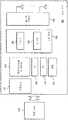
도 7은 본 발명의 실시예를 구현하는데 사용될 수 있는 하드웨어를 도시하는 도면, 7 illustrates hardware that can be used to implement an embodiment of the invention,
도 8은 본 발명에 따른 도 6a 내지 도 6d의 시스템에서 동작하도록 구성된 LTE 단말의 예시적인 구성 요소를 도시하는 도면. FIG. 8 illustrates exemplary components of an LTE terminal configured to operate in the system of FIGS. 6A-6D in accordance with the present invention. FIG.
확인 응답 시그널링을 제공하는 장치, 방법, 및 소프트웨어가 개시되어 있다. 설명을 위해서, 이하의 명세서에서는, 본 발명의 실시예에 대한 충분한 이해를 돕기 위한 다수의 특정한 상세한 설명들이 제공된다. 그러나, 당업자에게는 본 발명의 실시예가 이들 특정한 상세한 설명이 없어도 또는 동가의 배열을 이용하여 실행될 수 있음을 알 수 있다. 다른 예로, 공지의 구조 및 디바이스가 본 발명의 실시예를 불필요하게 모호하게 하는 것을 피하기 위해 블록도 형태로 도시되어 있다. Apparatus, methods, and software for providing acknowledgment signaling are disclosed. For purposes of explanation, in the following specification, numerous specific details are set forth in order to provide a thorough understanding of the embodiments of the present invention. However, it will be apparent to one skilled in the art that embodiments of the present invention may be practiced without these specific details or using equivalent arrangements. In other instances, well-known structures and devices are shown in block diagram form in order to avoid unnecessarily obscuring embodiments of the present invention.
본 발명의 실시예가 3세대 파트너쉽 프로젝트(3GPP) LTE 구조를 구비한 통신 네트워크와 관련하여 서술되어 있음에도 불구하고, 당업자라면, 본 발명의 실시예가 임의 유형의 통신 시스템에 적용가능하며 또한 유사한 성능을 가짐을 알 수 있다. Although embodiments of the present invention have been described in relation to communication networks with 3rd Generation Partnership Project (3GPP) LTE architectures, those skilled in the art are applicable to any type of communication system and have similar performance. It can be seen.
도 1은 본 발명의 실시예에 따라, 효율적인 확인 응답 시그널링을 제공할 수 있는 통신 시스템을 도시하는 도면이다. 도시된 바와 같이, 통신 시스템(100)은 액세스 네트워크(예컨대, WiMAX(Worldwide Interoperability for Microwave Access), 3GPP LTE(또는 E-UTRAN 또는 3.9G) 등)의 일부인 기지국(103) 등의 네트워크 장비(또는 네트워크 요소)와 통신하는 하나 이상의 사용자 단말(UE)(101)를 포함한다. 예를 들어, 통신 시스템(100)은 3GPP LTE 구조를 따른다. 3GPP LTE 구조(도 6a 내지 도 6d에 도시)하에서, 기지국(103)은 개선된 노드 B(eNB)로서 표시된다. UE(101)은 핸드셋, 단말, 스테이션, 유닛, 디바이스 등의 임의 유형의 이동국, 또는 사용자에 대한 임의 유형의 인터페이스("웨어러블(wearable)" 회로 등)일 수 있다. 1 is a diagram illustrating a communication system capable of providing efficient acknowledgment signaling, in accordance with an embodiment of the invention. As shown, the
UE(101)는 트랜시버(105)와, 트랜시버(105)에 결합하여 기지국(103)으로부터 신호를 송수신하는 안테나 시스템(107)을 포함한다. 안테나 시스템(107)은 하나 이상의 안테나(도면에 하나만 도시됨)를 포함할 수 있다. 따라서, 기지국(103)은 전자기 신호를 송수신하기 위해 하나 이상의 안테나(109)를 사용할 수 있다. UE(101)와 마찬가지로, 기지국(103)은 다운링크(DL)를 통해 UE(101)에 정보를 송신하는 트랜시버(111)를 사용한다. The UE 101 includes a
본 실시예에서, 기지국(103)은 OFDM(Orthogonal Frequency Divisional Multiplexing)을 다운링크(DL) 송신 방식으로서 이용하고, 업링크(UL) 송신 방식용으로 순환 프리픽스(cyclic prefix)를 가진 단일 캐리어 송신(예컨대, SC-FDMA( Single Carrier-Frequency Division Multiple Access)을 이용한다. SC-FDMA는, 2006년 5월 v.1.5.0, "Physical Layer Aspects for Evolved UTRA"의 제목으로 3GGP TR 25.814(전체적으로 본 명세서에 참조로서 포함되어 있음)에 상세히 기술된 DFT-S-OFDM을 또한 이용하여 실현될 수 있다. Multi-User-SC-FDMA로서도 불리는 SC-FDMA에 의해 복수의 사용자는 상이한 서브밴드상에서 동시에 송신할 수 있다. In this embodiment, the
일실시예에서, 통신 시스템(100)은 하이브리드 자동 반복 요청(HARQ) 기술을 이용하여 무선 간섭 처리량(air interference throughput)과 스펙트럼 효율성을 증가시킨다. 확인 응답/네거티브 확인 응답(ACK/NACK) 시그널링은 송신기와 수신기를 접속하기 위한 HARQ의 일부로서 고속 L1(계층 1 또는 물리층) 재송신을 가능하게 한다. 이와 같이, UE(101)와 기지국(103)은 송신 에러의 발생을 판단하고, HARQ 메카니즘에 따라 에러를 송신하는 원인을 통지하기 위해 확인 응답 시그널링 로직(113, 115)을 포함한다. 일실시예에서, 시스템(100)은 특히 LTE TDD 시스템에 대하여 다운링크(DL) 송신의 업링크(UL) ACK/NACK을 보냄으로써, 효율적이고 낮은 오버헤드를 가지며 강인성을 가진 확인 응답 시그널링 접근법이 제공된다. In one embodiment,
ACK/NACK 시그널링은 성공적으로 수신된 데이터 패킷을 재송신하지 않게 하거나, 송신중인 이전 데이터 패킷을 성공적으로 수신하기 전에 새로운 데이터 패킷을 송신하지 않게 하도록 충분한 강인성을 요구한다. 한편, 고속 L1 재송신으로 인해, 지정된 수신기로의 ACK/NACK 송신의 주파수가 매우 높아서(예컨대, 최대 1000Hz까지), 시그널링 오버헤드를 최소화하기 위해 ACK/NACK의 송신 효율성이 요구된다. 일실시예에 따른 시스템(100)은 도 2a 내지 도 2c에 상세히 도시된 바와 같이, 송신 효율성을 제공하는 확인 응답 시그널링 방법을 이용한다. ACK / NACK signaling requires sufficient robustness not to retransmit successfully received data packets or to transmit new data packets before successfully receiving previous data packets being transmitted. On the other hand, due to the fast L1 retransmission, the frequency of the ACK / NACK transmission to the designated receiver is very high (eg, up to 1000 Hz), so transmission efficiency of ACK / NACK is required to minimize signaling overhead. The
도 2a 내지 도 2c는 본 발명의 여러 실시예에 따라 효율적인 확인 응답 시그널링을 제공하는 프로세스의 흐름도이다. 실시예에서, 확인 응답 시그널링 프로세스는 도 1의 시스템과 관련해서 설명된다. 도 2a에 도시된 바와 같이, 단계(201)에서, 사전 결정된 수의 확인 응답/네거티브 확인 응답(AN) 채널이 대응하는 송신 채널에 대해 지정된다. 이러한 AN 채널의 할당은 확인 응답 시그널링 로직(115)을 이용하여 기지국(103)에 의해 수행될 수 있다. 예를 들어, 특정 수의 UL ACK/NACK(AN) 채널은 각 무선 프레임 또는 듀플렉스 스페이스마다 L1 다운링크 제어 시그널링으로 정의될 수 있으며, 여기서, 각 UL ACK/NACK 채널은 UL 공유 데이터 채널 중의 하나의 UL 서브프레임 송신에 대응한다. 단계(203)에서, AN 채널을 송신 채널에 매핑하는 것을 나타내는 메시지가 생성된다. 단계(205)에서와 같이, 이러한 메시지는 UE(101)에 송신된다. 2A-2C are flow diagrams of a process for providing efficient acknowledgment signaling in accordance with various embodiments of the present invention. In an embodiment, the acknowledgment signaling process is described in connection with the system of FIG. As shown in FIG. 2A, in
수신기측에서(도 2b에 도시), 제어 메시지는 UE(101)에 의해 수신되며, 여기서 단계(211)에 따르면, 메시지는 AN 채널을 송신 채널에 매핑하는 것을 명시한다. 이러한 예에서, UE(101)는 송신할 데이터를 구비하고 있어서, 데이터를 송신할 송신 채널 중 하나의 채널이 할당된다. 단계(213)에서, 데이터는 하나 이상의 송신 채널을 통해 송신되며, 그 다음, UE(101)는 확인 응답 시그널링을 위해 대응 AN 채 널을 모니터링한다. 이후에, 단계(215)에서와 같이, UE(101)는 송신된 데이터에 응답하여, 적절한 확인 응답 시그널링을 수신한다. At the receiver side (shown in FIG. 2B), a control message is received by the
도 2c는 상술한 프로세스가 수행되는 방법의 예를 도시한다. 이러한 시나리오하에서, 시스템(100)(특히, 예를 들어, BS(103))은, 단계(221)에서와 같이, 각각의 무선 프레임 또는 듀플렉스 스페이스에 대한 다운링크 제어 신호로 다수의 UL AN 채널을 규정한다. 예를 들어, 다수의 UL ACK/NACK(AN) 채널이 각각의 무선 프레임 또는 듀플렉스 스페이스별로 계층 1(L1 또는 물리층) 다운링크 제어 시그널링에서 사전 규정된다. 각각의 UL AN 채널은 UL 서브프레임의 대응하는 서브프레임 중 하나에 대해 ACK/NACK 비트의 송신을 지원한다. 2C shows an example of how the above-described process is performed. Under this scenario, the system 100 (especially BS 103), as in
UE(101)는 단계(223)에서 UL AN 채널의 위치를 획득한다. 시스템(100)이 AN 채널에 암묵적인 할당을 제공하면(단계(225)에서 결정되는 바와 같이), 단계(227)에 따라, 시스템(100)은 UL 서브프레임에 근거하여 AN 채널을 결정한다. 그러나, 시스템(100)이 암묵적인 할당을 제공하지 않으면, 단계(229)에서와 같이, 다운링크 내에서의 UL AN 채널의 위치를 이동하기 위해 시그널링 메시지가 송신된다. The
TDD 시스템의 구조에서, UE(101)는 사전 규정된 암묵적인 리소스 할당에 의해 또는 최소 시그널링 오버헤드의 사용을 통해 DL에서의 자신의 UL ACK/NACK 비트를 알 수 있다. 하나의 TDD 프레임 또는 하나의 듀플렉스 스페이스 내에 복수의 UL 및 DL 서브프레임이 존재할 수 있고, 하나의 UL 서브프레임에 복수의 스케줄링된 UE가 존재할 수 있기 때문에, 암묵적인 할당은 2개의 부분, 첫째로, i번째 UL 서브프레임에서의 데이터 송신에 대응하는 ACK/NACK의 타임 위치와, 두번째로, i번 째 UL 서브프레임에서 UL 데이터를 송신한 상이한 UE에 대한 ACK/NACK의 멀티플렉싱으로 볼 수 있다. In the structure of the TDD system, the
사전 규정된 매핑은 어느 DL 서브프레임이 i번째 UL 서브프레임에서의 데이터에 대해 ACK를 송신하는지를 표시하도록 지정될 수 있다. 실시예에서, AN 채널은 1 대 1로(고유하게) 상이한 UL 서브프레임에 매핑된다. 따라서, 어느 UL 서브프레임이 UL 데이터 패킷을 송신하고 있는지를 UE(101)가 알고 있는 한(UE(101)가 ACK/NACK를 수신할 준비를 하기 전에 이미 알고 있어야 함), UE(101)는 어느 AN 채널에 대해 경청(listen for)해야 하는지를 유일하게 알고 있을 것이다. UE(101)가 복수의 UL 서브프레임으로 데이터를 송신하고 있을 경우에, UE(101)는 자신의 ACK/NACK 비트에 대해 복수의 AN 채널을 경청할 것이다. The predefined mapping may be designated to indicate which DL subframe transmits an ACK for data in the i th UL subframe. In an embodiment, the AN channel is mapped one to one (uniquely) to different UL subframes. Thus, as long as the
상술한 프로세스를 판단하기 위해, 확인 응답 시그널링에 대한 다른 메카니즘을 검토하는 것이 바람직하다. In order to determine the process described above, it is desirable to review other mechanisms for acknowledgment signaling.
도 3a 및 도 3b는 각각 주파수 분할 듀플렉스(FDD) 및 시분할 듀플렉스(TDD)에 스케줄 시그널링 타이밍/로직을 제공하는 예시적인 시스템을 도시하는 도면이다. 도시된 바와 같이, 하나의 듀플렉스 스페이스(본 예에서는 5ms)에서, DL 스케줄링 시그널링은 FDD 및 TDD 구성(301, 303) 모두에 대해 유사한 방식으로 동작한다. 그러나, TDD는 UL에서와는 다르게 동작하며, 즉, 어느 하나의 DL 송신 시간 간격(TTI)에서의 UL 승인 시그널링 엔트리는 목표의 UE에 대한 어느 하나의 UL TTI에 할당될 수 있다. FDD 시스템에서, 각각의 UL 승인 시그널링 엔트리는 단 하나의 TTI만을 커버하는 반면에, TDD 시스템은, DL TTI가 UL TTI에 비해 적을 경우에, 하나의 TTI보다 큰 UL 승인 시그널링 엔트리를 제공할 수 있다. 3A and 3B are diagrams illustrating an example system that provides schedule signaling timing / logic for frequency division duplex (FDD) and time division duplex (TDD), respectively. As shown, in one duplex space (5 ms in this example), DL scheduling signaling operates in a similar manner for both FDD and
도 4a 및 도 4b는 FDD 업링크(UL) 확인 응답/네거티브 확인 응답(ACK/NACK) 타이밍 및 TDD UL ACK/NACK 타이밍 각각에 대한 예시적인 시스템을 도시하는 도면이다. 하나의 종래의 확인 응답 시그널링 메카니즘은 사용자 단말 식별자(ID)의 사용과 연관되어 있다. 전형적으로, ACK/NACK 신호는 사용되는 MIMO(Multiple Input Multipe Output) 방식에 따라 사용자 단말마다 1 또는 2 비트만을 가지고 있는 반면에, 예를 들어, UE ID가 16 비트 서명인 것으로 가정되는 LTE에서, UE ID는 그 ACK/NACK 비트보다 길어야 하기 때문에, ACK/NACK 비트에 목적지 식별로서 사용자 단말 ID(UE ID)를 첨부하는 것은 상당히 비효율적임을 알아야 한다. 따라서(오버헤드의 증가로 인해), UE ID를 시그널링하지 않고 목적지를 표시하는 것이 효율적인 ACK/NACK 송신을 위해 또한 ACK/NACK 비트 에러율, 즉 강인성을 개선시키는데 있어 바람직하다. 4A and 4B are diagrams illustrating example systems for FDD uplink (UL) acknowledgment / negative acknowledgment (ACK / NACK) timing and TDD UL ACK / NACK timing, respectively. One conventional acknowledgment signaling mechanism is associated with the use of a user terminal identifier (ID). Typically, the ACK / NACK signal has only 1 or 2 bits per user terminal depending on the Multiple Input Multipe Output (MIMO) scheme used, whereas, for example, in LTE where a UE ID is assumed to be a 16 bit signature, Since the UE ID must be longer than its ACK / NACK bit, it should be noted that appending a user terminal ID (UE ID) as a destination identification to the ACK / NACK bit is quite inefficient. Thus (due to increased overhead), indicating the destination without signaling the UE ID is desirable for efficient ACK / NACK transmission and also for improving the ACK / NACK bit error rate, i.e., robustness.
도 4a에 도시된 바와 같이, FDD 시스템(401)의 FDD UL ACK/NACK 타이밍은 오히려 간단하다. 그러나, 시분할 듀플렉스(TDD) 시스템(403)에서, DL 송신에서 복수의 UL ACK/NACK를 필요로 하는 하나 이상의 UL 서브프레임 송신이 종종 있다(도 4b에 도시). UE-ID 외에, 이는 ACK/NACK 신호의 목적지 식별의 추가적인 시간 도메인 차원을 증가시킨다. As shown in FIG. 4A, the FDD UL ACK / NACK timing of the
또한, TDD의 경우에, 다른 종래의 접근법은 DL 서브프레임에서 UL ACK/NACK 를 송신할 때 결과적으로 시간 도메인이 모호해진다. Also, in the case of TDD, another conventional approach results in ambiguous time domain when transmitting UL ACK / NACK in DL subframe.
대조적으로, 도 2a 내지 도 2c의 프로세스는, 특히 UL 서브프레임의 개수가 무선 프레임에서 DL 서브프레임의 개수보다 많을 경우에, TDD 시스템의 양호한 강인성을 유지할 뿐만 아니라, UL ACK/NACK 비트를 최소화한다(예컨대, (MIMO 전개에 따라) UE마다 1 또는 2 비트만큼 낮음). In contrast, the process of FIGS. 2A-2C not only maintains good robustness of the TDD system, but also minimizes UL ACK / NACK bits, especially when the number of UL subframes is greater than the number of DL subframes in the radio frame. (Eg, as low as 1 or 2 bits per UE (depending on MIMO deployment)).
도 5는 본 발명의 실시예에 따라 다운링크에서의 예시적인 TDD UL ACK/NACK 채널을 도시하는 도면이다. 이러한 예에서, 특정 실시예에 따라, 확인 응답 시그널링 접근법은 TDD 시스템에서 UL ACK/NACK 송신을 보낸다. 무선 프레임(501)마다 m개의 UL 서브프레임이 있다고 가정하면, 기지국(103)은 그 무선 프레임(501)에서의 다운링크 제어 시그널링에 m개의 UL AN 채널(503)을 규정한다. 이들 m개의 UL AN 채널(503)은 다운링크 서브프레임 중 하나 또는 일부 또는 모두에 사전 할당될 수 있으며, 이들 m개의 UL AN 채널(503)의 위치는 전체적인 LTE 시스템 조건에 따라 정적, 반 정적, 또는 동적일 수 있다. 이들 m개의 UL AN 채널(503)의 위치는, 본 실시예에서, 무선 리소스 제어(RRC) 시그널링(정적 또는 반 정적), 브로드캐스트 채널(BCH) 시그널링(정적 또는 반 정적 또는 동적), 또는 CatO 시그널링(정적 또는 반 정적 또는 동적)을 통해 모든 UE에 시그널링 또는 브로드캐스팅된다. 5 is a diagram illustrating an exemplary TDD UL ACK / NACK channel in the downlink according to an embodiment of the present invention. In this example, according to a particular embodiment, the acknowledgment signaling approach sends UL ACK / NACK transmissions in the TDD system. Assuming there are m UL subframes per
각각의 UL AN 채널(503)은, 예를 들어, 신뢰성있고 효율적인 공지의 여러 방법에 의해, 스케줄링의 UE(101)에 대한 UL ACK/NACK 비트를 이미 알고 있는 서브프레임(TTI)으로 송신할 수 있다. 또한, 필요한 처리 시간이 ACK/NACK가 송신될 수 있을 때까지 최소/최단 기간을 규정하도록, 타이밍 조건이 명시될 수 있다. LTE 예에서, 이러한 최소/최단 기간은, 처리 시간을 충족하고 수비학(numerology)에 맞는(예를 들어, -400㎲이 최장의 터보 코드 블록을 디코딩하는데 적합하다) 값(예컨 대, 1ms)일 수 있다. 도시된 바와 같이, 처리 시간이 불충분하기 때문에, AN-3를 DL 서브프레임-1이 아닌 DL 서브프레임-2만으로 매핑할 수 있음을 알 수 있다. Each
또한, 동일 DL 서브프레임에서의 ACK-NACK는 다양한 표준 기술(예컨대, 주파수 분할 다중화, 코드 분할 다중화, 또는 하이브리드 방식)을 이용하여 다중화될 수 있으며, UE(101)는 UE(101)를 AN 채널 내에서 인덱싱함으로써 하나의 AN 채널 내에서의 정확한 위치를 결정할 수 있다. 다른 기술이 또한 사용될 수 있음을 알아야 한다. 이들 접근법하에서, 기지국(예컨대, 기지국(103))은, 서브프레임 k에서, 단말(예컨대, UE-n)에게 x번째 L1/L2 제어 채널을 이용하여 UL 무선 리소스 할당을 통지하며, 서브프레임 k+t에서, 기지국은 AN 채널의 x번째 L1/L2 무선 리소스(x번째 서브캐리어 세트 또는 x번째 코드)를 이용하여 UL AN을 UE-n으로 이동시킨다. In addition, the ACK-NACK in the same DL subframe may be multiplexed using various standard techniques (eg, frequency division multiplexing, code division multiplexing, or a hybrid scheme), and the
상술한 확인 응답 시그널링 접근법은 DL 다운에서의 UL ACK/NACK 송신을 위한 필요한 비트를 최소한으로, 즉 사용자 단말 당 1 비트로 최소화하는 효율적이고 강인한 기술을 제공한다. 또한, 이러한 접근법은 TDD 시스템에서 및 다른 비동적 스케줄된 사용자 단말에 대한 UL AN 채널 구조에서 다양한 다운링크/업링크 구성의 시나리오를 지원하는데 있어 융통성이 있으며 일관성이 있다. 또한, 이러한 접근법은 TDD 시스템에서 UL AN 채널 위치를 유지함에 있어 융통성을 가지고 있으며, 즉, 각각의 DL 서브프레임에서 UL AN 채널을 반드시 가지고 있을 필요가 없고, 각각의 DL 서브프레임에서 단 하나의 UL AN 채널만을 반드시 가지고 있을 필요도 없다. 이것은 UL 스케줄러 및 UL 송신에 있어 보다 많은 여지를 남길 수 있으며, TDD 시스템에 있어서의 라운트 트립 지연의 이득을 잠재적으로 얻을 수 있다. The acknowledgment signaling approach described above provides an efficient and robust technique for minimizing the necessary bits for UL ACK / NACK transmission on the DL down to a minimum, i.e., 1 bit per user terminal. In addition, this approach is flexible and consistent in supporting scenarios of various downlink / uplink configurations in the TDD system and in the UL AN channel structure for other non-dynamically scheduled user terminals. In addition, this approach is flexible in maintaining UL AN channel position in a TDD system, i.e., it is not necessary to have a UL AN channel in each DL subframe, and only one UL in each DL subframe. It is not necessary to have only AN channel. This may leave more room for the UL scheduler and UL transmission, potentially gaining the benefit of the round trip delay in a TDD system.
도 6a 내지 도 6d는 본 발명의 여러 실시예에 따라 도 1a의 시스템을 동작시킬 수 있는 예시적인 LTE 구조를 구비한 통신 시스템의 도면이다. 예를 들어(도 1에 도시), 기지국 및 UE는 시분할 다중 접속(TDMA), 코드 분할 다중 접속(CDMA), 광대역 코드 분할 다중 접속(WCDMA), 직교 주파수 분할 다중 접속(OFDMA) 또는 단일 캐리어 주파수 분할 다중 접속(SC-FDMA) 또는 이들의 조합 등의 임의의 액세스 방법을 이용하여 시스템(600) 내에서 통신할 수 있다. 실시예에서, 업링크 및 다운 링크는 모두 WCDMA를 이용할 수 있다. 다른 실시예에서, 업링크는 SC-FDMA를 이용하는 반면에, 다운링크는 OFDMA를 이용한다. 6A-6D are diagrams of communication systems with an exemplary LTE architecture capable of operating the system of FIG. 1A in accordance with various embodiments of the invention. For example (shown in FIG. 1), the base station and the UE can be divided into time division multiple access (TDMA), code division multiple access (CDMA), wideband code division multiple access (WCDMA), orthogonal frequency division multiple access (OFDMA), or single carrier frequency. Any access method, such as split multiple access (SC-FDMA) or a combination thereof, may be used to communicate within the
MME(Mobile Management Entity)/서빙 게이트웨이(601)는 패킷 트랜스포트 네트워크(예컨대, 인터넷 프로토콜(IP) 네트워크)(603)를 통한 터널링을 이용하여 전체 또는 부분의 메시 구조로 eNB에 접속된다. MME/서빙 게이트웨이(601)의 예시적인 기능은, 페이징 메시지를 eNB에 분배하는 기능과, IP 헤더 압축, 원인을 페이징하는 U 평면 패킷의 종료, 및 UE 이동성의 지원을 위한 U 평면의 스위칭의 기능을 포함한다. 게이트웨이(601)는 예를 들어, 인터넷 또는 사설 네트워크(603) 등의 외부 네트워크에 대한 게이트웨이로서 기능하기 때문에, 게이트웨이(601)는, 사용자의 식별 및 특별 권한을 안전하게 판단하고 각각의 사용자의 활동성을 추적(track)하기 위해, 액세스, 권한 검증(Authorization), 과금(Accounting) 시스템(AAA)(605)을 포함한다. 즉, MME 서빙 게이트웨이(601)는 LTE 액세스 네트워크를 위한 키 제어 노드이며, 재송신을 포함한 아이들(idle) 모드 UE 트래킹 및 페이 징 과정을 담당한다. 또한, MME(601)는 베이러(bearer) 활성화/활성화 해제 프로세스와 연관되며, 코어 네트워크(CN) 노드 재할당을 포함하는 인트라 LTE 핸드오버의 시점과 초기 부착시에 UE에 맞는 SGW(서빙 게이트웨이)를 선택하는 것을 담당한다. The Mobile Management Entity (MME) /
LTE 인터페이스에 대한 보다 상세한 설명은, 전체적으로 본 명세서에 참조로서 포함되는, "E-UTRA and E-UTRAN: Radio Interface Protocol Aspects"의 3GPP TR 25.813에 제공된다. A more detailed description of the LTE interface is provided in 3GPP TR 25.813 of "E-UTRA and E-UTRAN: Radio Interface Protocol Aspects", which is incorporated herein by reference in its entirety.
도 6b에서, 통신 시스템(602)은 GERAN(GSM/EDGE 무선 액세스)(604), 및 UTRAN(606) 기반의 액세스 네트워크, E-UTRAN(612) 및 비 3GPP(도시 생략) 기반의 액세스 네트워크를 지원하며, 전체적으로 본 명세서에 참조로서 포함되는 TR 23.882에 보다 상세히 설명되어 있다. 이러한 시스템의 중요 특징은 제어 평면 기능을 수행하는 네트워크 객체(MME(608))와 베이러 평면 기능을 수행하는 네트워크 객체(서빙 게이트웨이(610))를 그들 사이의 공지된 오픈 인터페이스를 이용하여 분리하는 것이다(S11). E-UTRAN(612)은 보다 높은 대역폭을 제공하여 기존의 서비스를 개선할 뿐만 아니라 새로운 서비스를 가능하게 하기 때문에, 서빙 게이트웨이(610)로부터의 MME(608)를 분리하는 것은 서빙 게이트웨이(610)가 시그널링 트랜잭션에 적합한 플랫폼을 기반으로 할 수 있다는 것을 암시한다. 이러한 방식에 의해, 이들 2개의 구성 요소 각각의 독립적인 스케일링뿐만 아니라, 비용면에서 보다 효율적인 플랫폼을 선택할 수 있다. 서비스 공급자는, 최적의 대역폭 대기 시간을 감소시키고 집중되는 실패 지점을 피하기 위해서, MME(608)의 위치와는 무관하게 네트워크 내에서의 서빙 게이트웨이(610)의 최적의 토포로지 위치를 또한 선택할 수 있다. In FIG. 6B, the
시스템(602)의 기본 구조는 이하의 네트워크 요소를 포함한다. 도 6b에 도시된 바와 같이, E-UTRAN(예를 들어, eNB)(612)은 LTE-Uu와 인터페이스한다. E-UTRAN(612)은 LTE 무선 인터페이스를 지원하며, 제어 평면 MME(608)에 대응하는 무선 리소스 제어(RRC) 기능에 맞는 기능을 포함한다. 또한, E-UTRAN(612)은 무선 리소스 관리, 승인 제어, 스케줄링, 협정된 업링크(UL) QoS(서비스 품질)의 시행, 셀 정보 브로드캐스트, 사용자의 암호화/암호화 해제, 다운링크 및 업링크 사용자 평면 패킷 헤더 및 패킷 데이터 수렴 프로토콜(PDCP)의 압축/압축 해제를 포함하는 여러 기능을 수행한다. The basic structure of
MME(608)는, 키 제어 노드로서, 이동성 UE(101) 식별 및 보안 파라미터를 관리하고, 재송신을 포함한 과정의 페이징을 담당한다. MME(608)는 베이러 활성화/활성화 해제 프로세스에 연관되어 있으며, UE에 맞는 서빙 게이트웨이(610)의 선택을 담당한다. MME(608)의 기능은 비 액세스 층(Non Access Stratum)(NAS) 시그널링 및 관련 보안을 포함한다. MME(608)는 UE(101)의 권한 부여를 체크하여 서비스 제공자의 공중 육상 이동 네트워크(Public Land Mobile Network : PLMN) 상에 자리잡고 UE 로밍 규정을 실시한다. 또한, MME(608)는 LTE와 2G/3G 액세스 네트워크 사이의 이동성을 위한 제어 평면 기능에, SGSN(서빙 GPRS 서포트 노드)(614)로부터 MME(608)에서 종료하는 S3 인터페이스를 제공한다. E-UTRA에서의 PLMN 선택의 원칙은 3GPP PLMN 선택 원칙을 기반으로 한다. 셀 선택은 MME_DETACHED로부터 EMM- IDLE 또는 EMM-CONNECTED로의 이동을 필요로 할 수 있다. 셀 선택은 UE NAS가 하나의 선택된 PLMN 및 동등한 PLMN을 식별할 경우에 이루어질 수 있다. UE(101)는 E-UTRA 주파수 대역을 검색하고, 각 캐리어 주파수에 대해, 최강의 셀을 식별한다. 또한, UE(101)는 자신의 PLMN를 식별하기 위해 셀 시스템 정보 브로드캐스트를 판독한다. 또한, UE(101)는 적합한 셀을 식별하기 위해 탐색하고, 적합한 셀을 식별할 수 없는 경우에는, 수용가능한 셀을 식별하기 위해 탐색한다. 적합한 셀이 발견되었을 때, 또는 단 하나의 수용가능한 셀이 발견된 경우에, UE(101)는 그 셀 상에 위치하여 셀 재선택 과정을 개시한다. 셀 선택으로 UE(101)가 위치한 셀을 식별한다. The
SGSN(614)은 자신의 지리적인 서비스 영역 내에서 이동국으로 데이터 패킷의 전달을 담당한다. 이러한 작업은 패킷 라우팅 및 송신, 이동성 관리, 논리 링크 관리, 및 인증 및 청구 기능을 포함한다. S6a 인터페이스에 의해, MME(608)과 HSS(홈 가입자 서버)(616) 사이의 관련 시스템(AAA 인터페이스)에 인증/권한 부여 사용자 액세스를 위한 가입 및 인증 데이터를 송신할 수 있다. MME(608) 간의 S10 인터페이스는 MME 위치 및 MME(608)를 MME(608) 정보 송신에 제공한다. 서빙 게이트웨이(610)는 S1-U를 통해 E-UTRAN(612)을 향해 인터페이스를 종단으로 하는 노드이다.
S1-U 인터페이스는, E-UTRAN(612)와 서빙 게이트웨이(610) 사이에, 베이러마다 사용자 평면 터널링(a per bearer user plane tunneling)을 제공한다. 이것은 eNB(612) 간의 핸드오버 동안에 경로 스위칭에 대한 지원을 포함한다. S4 인터페 이스는 SGSN(614) 간의 관련 제어 및 이동성 지원과, 서빙 게이트웨이(610)의 3GPP 앵커 기능을 사용자 평면에 제공한다. The S1-U interface provides a per bearer user plane tunneling between the E-UTRAN 612 and the serving
S12는 UTRAN(606)와 서빙 게이트웨이(610) 간의 인터페이스이다. 패킷 데이터 네트워크(PDN) 게이트웨이(618)는, UE(101)에 대한 트래픽의 출구 및 입구 포인트로 되게 함으로써, UE(101)로의 접속성을 외부 패킷 데이터 네트워크에 제공한다. PDN 게이트웨이(618)는 폴리시 시행, 각 유저에 대한 패킷 필터링, 과금 지원, 적법한 인터셉트(lawful interception), 및 패킷 스크린을 수행한다. PDN 게이트웨이(618)의 다른 역할은 WiMAX 및 3GPP2(CDMA 1X 및 EvDO(Evolution Data Only)) 등의 3GPP와 비 3GPP 기술 사이의 이동성의 앵커로서 동작하는 것이다. S12 is an interface between the
S7 인터페이스는 QoS 폴리시 및 과금 규칙을 PCRF(Policy and Charging Role Function)(620)로부터 PDN 게이트웨이(618)의 폴리시 및 과금 시행 기능(PCEF)으로 변경하는 것을 제공한다. SGi 인터페이스는 PDN 게이트웨이와, 패킷 데이터 네트워크(622)를 포함한 운영자의 IP 서비스 사이의 인터페이스이다. 패킷 데이터 네트워크(622)는, 예를 들어, IMS(IP Multimedia Subsystem) 서비스를 제공하기 위한, 운영자의 외부 공중 또는 사설 패킷 데이터 네트워크 또는 인트라 조작자 패킷 데이터 네트워크일 수 있다. Rx+ 는 PCRF와 패킷 데이터 네트워크(622) 사이의 인터페이스이다. The S7 interface provides for changing the QoS policy and charging rules from the policy and charging role function (PCRF) 620 to the policy and charging enforcement function (PCEF) of the
도 6c에 도시된 바와 같이, eNB는 E-UTRA(Evolved Universal Terrestrial Radio Access)(사용자 평면, 예컨대, 제어 평면(예컨대, RRC(621))뿐만 아니라, RLC(무선 링크 제어)(615), MAC(미디어 액세스 제어)(617), PHY(물리적)(619))을 이용한다. 또한, eNB(103)는 상호 셀 RRM(무선 리소스 관리)(623), 접속 이동성 제어(625), RB(무선 베이러) 제어(627), 무선 승인 제어(629), eNB 측정 구성 및 제공(631), 및 동적 리소스 할당(스케줄러)(633)의 기능을 포함한다. As shown in FIG. 6C, the eNB is not only an Evolved Universal Terrestrial Radio Access (E-UTRA) (user plane, eg, control plane (eg, RRC 621)), but also RLC (Radio Link Control) 615, MAC (Media access control) 617, PHY (physical) 619). In addition, the
eNB(103)는 S1 인터페이스를 통해 aGW(601)(액세스 게이트웨이)와 통신한다. aGW(601)는 사용자 평면(601a)과 제어 평면(601b)을 포함한다. 제어 평면(601b)은 SAE(시스템 구조 레볼루션) 베이러 제어(635) 및 MM(이동 관리) 객체(637)를 제공한다. 사용자 평면(601b)은 PDCP(패킷 데이터 수렴 프로토콜)(639)와 사용자 평면 기능(641)을 포함한다. aGW(601)의 기능은 서빙 게이트웨이(SGW)와 패킷 데이터 네트워크(PDN)(GW)의 결합에 의해 또한 제공될 수 있음을 알아야 한다. 또한, aGW(601)는 인터넷(643) 등의 패킷 네트워크와 인터페이스할 수 있다. The
도 6d에 도시된 바와 같이, 다른 실시예에서, PDCP(패킷 데이터 수렴 프로토콜) 기능은 GW(601)보다는 eNB에 존재할 수 있다. 이러한 PDCP 능력 외에, 또한, 도 6c의 eNB 기능은 이러한 구조로 제공된다. As shown in FIG. 6D, in another embodiment, PDCP (Packet Data Convergence Protocol) functionality may be present at the eNB rather than the
도 6d의 시스템에서, E-UTRAN과 EPC(Evolved Packet Core) 사이에는 기능적인 분할이 제공된다. 이러한 예에서, E-UTRAN의 무선 프로토콜 구조는 사용자 평면 및 제어 평면에 맞게 제공된다. 이러한 구조에 대한 보다 상세한 설명은 3GPP TS 36.300에 제공되어 있다. In the system of FIG. 6D, functional partitioning is provided between the E-UTRAN and the Evolved Packet Core (EPC). In this example, the radio protocol architecture of the E-UTRAN is provided for the user plane and the control plane. A more detailed description of this structure is provided in 3GPP TS 36.300.
eNB는, S1을 통해, 이동성 앵커 기능(647)을 포함하는 서빙 게이트웨이(645)에, 또한, UE IP 어드레스 할당 기능(657) 및 패킷 필터링 기능(659)을 제공하는 패킷 게이트웨이(P-GW)(649)에 인터페이스한다. 이러한 구조에 따르면, MME(이동 성 관리 객체)(661)는 SAE(시스템 구조 레볼루션) 베이러 제어(651), 아이들 상태 이동성 핸들링(653), NAS(비 액세스 층) 보안(655)을 제공한다. The eNB, via S1, provides a packet gateway (P-GW) that provides a serving
당업자라면, 확인 응답 시그널링의 프로세스는 소프트웨어, 하드웨어(예컨대, 범용 프로세서, 디지털 신호 프로세싱(DSP) 칩, 주문형 집적 회로(ASIC), 필드 프로그램가능 게이트 어레이(FPGA) 등), 펌웨어, 또는 이들의 조합을 통해 구현될 수 있음을 인식할 것이다. 상술한 기능을 수행하는 하드웨어의 예는 도 7과 관련시켜 이하에 상세히 설명된다. Those skilled in the art will appreciate that the process of acknowledgment signaling may be software, hardware (eg, general purpose processor, digital signal processing (DSP) chip, application specific integrated circuit (ASIC), field programmable gate array (FPGA), etc.), firmware, or a combination thereof. It will be appreciated that this may be implemented via. Examples of hardware for performing the above functions are described in detail below in connection with FIG.
도 7은 본 발명의 여러 실시예를 구현할 수 있는 하드웨어의 예를 도시한다. 연산 시스템(700)은 버스(701) 또는 정보를 통신하는 다른 통신 메카니즘과, 버스(701)에 연결되어 정보를 처리하기 위한 프로세서(703)를 포함한다. 연산 시스템(700)은, 버스(701)에 연결되어 프로세서(703)에 의해 실행되는 정보 및 명령어를 저장하기 위한 랜덤 액세스 메모리(RAM) 또는 다른 동적 저장 장치 등의 메인 메모리(705)를 더 포함한다. 또한, 메인 메모리(705)는, 프로세서(703)에 의해 명령어를 실행하는 동안에, 임시 변수 또는 다른 중간 정보를 저장하기 위해 사용될 수 있다. 연산 시스템(700)은, 버스(701)에 연결되어 프로세서(703)에 있어서의 정적 정보 및 명령어를 저장하기 위한 판독 전용 메모리(ROM)(707) 또는 다른 정적 저장 장치를 더 포함할 수 있다. 자기 디스크 또는 광학 디스크 등의 저장 장치(709)는 버스(701)에 연결되어 정보 및 명령어를 영구적으로 저장하기 위한 것이다. 7 illustrates an example of hardware that may implement various embodiments of the present invention. The
연산 시스템(700)은, 정보를 사용자에게 표시하기 위해, 액정 디스플레이, 또는 액티브 매트릭스 디스플레이 등의 디스플레이(711)에 버스(701)를 통해 연결될 수 있다. 알파벳 및 다른 키를 포함하는 키보드 등의 입력 장치(713)는 버스(701)에 연결되어 프로세서(703)에 정보 및 명령어 선택을 송수신하기 위한 것이다. 입력 장치(713)는, 프로세서(703)에 방향 정보 및 명령어 선택을 송수신하기 위한, 또한, 디스플레이(711) 상에서의 커서 움직임을 제어하기 위한 마우스, 트랙볼, 또는 커서 방향 키 등의 커서 제어 장치를 포함할 수 있다. The
본 발명의 여러 실시예에 따르면, 본 명세서에 기재된 프로세스는 메인 메모리(705)에 포함된 명령어의 배열을 실행하는 프로세서(703)에 응답하여 연산 시스템(700)에 의해 제공될 수 있다. 이러한 명령어는 저장 장치(709) 등의 다른 컴퓨터 판독가능 매체로부터 메인 메모리(705)에서 판독될 수 있다. 메인 메모리(705)에 포함된 명령어들의 배열을 실행하여, 프로세서(703)는 본 명세서에 기재된 프로세스 단계를 수행할 수 있다. 또한, 멀티프로세싱 배열에서의 하나 이상의 프로세스는 메인 메모리(705)에 포함된 명령어를 실행하는데 사용될 수 있다. 다른 실시예에서, 하드 배선의 회로는 본 발명의 실시예를 실행하기 위해 소프트웨어 명령어와 결합하여 또는 소프트웨어 명령어를 대신하여 사용될 수 있다. 다른 예에서, 필드 프로그램가능 게이트 어레이(FPGA) 등의 재구성가능 하드웨어가 사용될 수 있으며, 여기서, 자신의 논리 게이트의 기능 및 접속 토포로지는 런 타임으로, 특히 메모리 룩업 테이블을 프로그래밍함으로써, 주문 제작가능하다. 따라서, 본 발명의 실시예는 하드웨어 회로 및 소프트웨어의 특정 결합으로 한정되지 않는다. According to various embodiments of the present invention, the processes described herein may be provided by the
또한, 연산 시스템(700)은 버스(701)에 연결된 적어도 하나의 통신 인터페이 스(715)를 포함한다. 통신 인터페이스(715)는 네트워크 링크(도시 생략)와의 양방향 데이터 통신 결합을 제공한다. 통신 인터페이스(715)는 여러 유형의 정보를 나타내는 디지털 데이터 스트림을 전송하는 전기, 전자기, 또는 광학 신호를 송수신한다. 또한, 통신 인터페이스(715)는 범용 직렬 버스(USB) 인터페이스, PCMCIA(퍼스널 컴퓨터 메모리 카드 인터내셔널 어소시에이션) 인터페이스 등의 주변 인터페이스 장치를 포함할 수 있다. The
프로세서(703)는 수신되는 동안의 송신된 코드를 실행하고/실행하거나 추후 실행을 위해 저장 장치(709), 또는 다른 비휘발성 저장 장치에 코드를 저장할 수 있다. 이러한 방식으로, 연산 시스템(700)은 반송파의 형태로 애플리케이션 코드를 얻을 수 있다. The
본 명세서에 사용된 용어 "컴퓨터 판독가능 매체"는 실행을 위해 프로세서(703)에 명령어를 제공하는데 관여하는 임의의 매체를 지칭한다. 이러한 매체는 비휘발성 매체, 휘발성 매체, 및 송신 매체로 제한되지 않고 이들 매체를 포함하는 여러 형태를 취할 수 있다. 예를 들어, 비휘발성 매체는 저장 장치(709) 등의 광학 또는 자기 디스크를 포함한다. 휘발성 매체는 메인 메모리(705) 등의 동적 메모리를 포함한다. 송신 매체는 버스(701)를 포함하는 와이어를 포함하여, 동축 케이블, 구리 와이어, 및 광섬유를 포함한다. 또한, 송신 매체는, 무선 주파수(RF) 및 적외선(IR) 데이터 통신중에 발생되는 파형 등의 음향, 광학 또는 전자기파의 형태를 취할 수 있다. 예를 들어, 컴퓨터 판독가능 매체의 일반적인 형태는 플로피 디스크, 플렉시블 디스크, 하드 디스크, 자기 테이프, 임의의 다른 자기 매체, CD-ROM, CDRW, DVD, 또는 다른 광학 매체, 번치 카드, 페이퍼 테이프, 광학 마크 시트, 홀 또는 다른 광학적으로 인식가능한 표시의 패턴을 가진 임의의 다른 물리 매체, RAM, PROM, EPROM, FLASH-EPROM, 임의의 다른 메모리 칩 또는 카트리지, 반송파, 또는 컴퓨터에 의해 판독가능한 다른 매체를 포함한다. The term "computer readable medium" as used herein refers to any medium that participates in providing instructions to the
컴퓨터 판독가능 매체의 여러 형태는 실행을 위해 프로세서에 명령어를 제공하는데 관여될 수 있다. 예를 들어, 본 발명의 적어도 일부를 실행하기 위한 명령어는 원격 컴퓨터의 자기 디스크 상에 초기에 내장될 수 있다. 이러한 시나리오에서, 원격 컴퓨터는 메인 메모리에 명령어를 실어서, 모뎀을 이용한 전화선을 통해, 또는 무선 링크를 통해서 명령어를 송신한다. 로컬 시스템의 모뎀은 전화선을 통해 데이터를 수신하며, 적외선 송신기를 이용하여 데이터를 적외선 신호로 변환하고 그 적외선 신호를 PDA 또는 랩탑 등의 휴대가능 연산 장치에 송신할 수 있다. 휴대가능 연산 장치 상의 적외선 검출기는 적외선 신호에 포함된 정보 및 명령어를 수신하여 데이터를 버스 상에 배치한다. 버스는 데이터를 메인 메모리에 운송하고, 프로세서는 명령어를 검색하여 실행한다. 메인 메모리에 의해 수신된 명령어는 프로세서에 의한 실행 전후에 저장 장치 상에 광학적으로 저장될 수 있다. Various forms of computer readable media may be involved in providing instructions to a processor for execution. For example, instructions for carrying out at least part of the invention may be initially embedded on a magnetic disk of a remote computer. In such a scenario, the remote computer loads the instructions into main memory to send the instructions over a telephone line using a modem or over a wireless link. The modem of the local system receives data via a telephone line, and may use an infrared transmitter to convert the data into an infrared signal and transmit the infrared signal to a portable computing device such as a PDA or laptop. An infrared detector on the portable computing device receives the information and instructions contained in the infrared signal and places the data on the bus. The bus carries data to main memory, and the processor retrieves and executes the instructions. Instructions received by the main memory may be optically stored on the storage device before and after execution by the processor.
도 8은 본 발명의 실시예에 따라, 도 6a 내지 도 6d의 시스템에서 동작가능한 LTE 단말의 예시적인 구성 요소를 도시하는 도면이다. LTE 단말(800)은 MIMO 시스템에서 동작하도록 구성되어 있다. 결론적으로, 안테나 시스템(801)은 신호를 송수신하는 복수의 안테나용으로 제공한다. 안테나 시스템(801)은 복수의 송신기(805) 및 수신기(807)를 포함하는 무선 회로(803)에 연결되어 있다. 무선 회로 는 베이스 밴드 프로세싱 회로뿐만 아니라 무선 주파수(RF) 회로 모두를 포함한다. 도시된 바와 같이, 계층 1(L1) 및 계층 2(L2) 프로세싱은 유닛(809) 및 유닛(811) 각각에 의해 제공된다. 옵션으로, 계층 3 기능이 제공될 수 있다(도시 생략). 모듈(813)은 모든 MAC 계층 기능을 실행한다. 타이밍 및 캘리브레이션 모듈(815)은 예를 들어, 외부 타이밍 레퍼런스(도시 생략)를 인터페이스함으로써 적절한 타이밍을 유지한다. 추가로, 프로세서(817)가 포함된다. 이러한 시나리오하에서, LTE 단말(800)은 퍼스널 컴퓨터, 워크 스테이션, PDA, 웹 어플라이언스(web appliance), 셀룰러 폰일 수 있는 연산 장치(819)와 통신한다. FIG. 8 is a diagram illustrating exemplary components of an LTE terminal operable in the system of FIGS. 6A-6D, in accordance with an embodiment of the invention. The LTE terminal 800 is configured to operate in a MIMO system. In conclusion, the
본 발명은 다수의 실시예 및 구현예와 결부시켜 설명되었지만, 본 발명은 첨부한 청구범위의 범위내에 포함되는 여러 자명한 수정 및 동등한 배열을 커버하지만 이들로 제한되지 않는다. 본 발명의 특징이 청구범위 중의 특정 결합으로 표현되었지만, 이들 특징은 임의의 결합 및 순서로 배열될 수 있음이 예측된다.While the invention has been described in connection with numerous embodiments and embodiments, the invention covers, but is not limited to, many obvious modifications and equivalent arrangements falling within the scope of the appended claims. While features of the invention have been expressed in terms of specific combinations in the claims, it is contemplated that these features may be arranged in any combination and order.
Claims (34)
Applications Claiming Priority (3)
| Application Number | Priority Date | Filing Date | Title |
|---|---|---|---|
| US88823007P | 2007-02-05 | 2007-02-05 | |
| US60/888,230 | 2007-02-05 | ||
| PCT/IB2008/000251 WO2008096232A1 (en) | 2007-02-05 | 2008-02-05 | Method and apparatus for providing acknowledgment signaling |
Publications (2)
| Publication Number | Publication Date |
|---|---|
| KR20090107565A KR20090107565A (en) | 2009-10-13 |
| KR101185664B1 true KR101185664B1 (en) | 2012-09-24 |
Family
ID=39365638
Family Applications (1)
| Application Number | Title | Priority Date | Filing Date |
|---|---|---|---|
| KR1020097018530A Active KR101185664B1 (en) | 2007-02-05 | 2008-02-05 | Method and apparatus for providing acknowledgment signaling |
Country Status (6)
| Country | Link |
|---|---|
| US (1) | US20100027495A1 (en) |
| EP (1) | EP2115927A1 (en) |
| KR (1) | KR101185664B1 (en) |
| CN (1) | CN101578804A (en) |
| MX (1) | MX2009005898A (en) |
| WO (1) | WO2008096232A1 (en) |
Families Citing this family (15)
| Publication number | Priority date | Publication date | Assignee | Title |
|---|---|---|---|---|
| CN101675691B (en) * | 2007-03-01 | 2013-07-10 | 株式会社Ntt都科摩 | Base station device, user device, and communication control method |
| EP3110060B1 (en) * | 2007-04-11 | 2018-06-13 | Telefonaktiebolaget LM Ericsson (publ) | Method and apparatus in a telecommunication system |
| KR20080092222A (en) * | 2007-04-11 | 2008-10-15 | 엘지전자 주식회사 | Data Transfer Method in TD System |
| US8036166B2 (en) * | 2007-06-18 | 2011-10-11 | Nokia Corporation | Signaling of implicit ACK/NACK resources |
| JP5209346B2 (en) * | 2008-03-05 | 2013-06-12 | 株式会社エヌ・ティ・ティ・ドコモ | Transmission device, transmission method, reception device, and reception method |
| MX2011004217A (en) | 2008-10-21 | 2011-06-20 | Merial Ltd | Thioamide compounds, method of making and method of using thereof. |
| AR074024A1 (en) | 2008-11-14 | 2010-12-15 | Merial Ltd | COMPOSITE OF ARILAZOL-2-IL-CYANOETHYLAMIN ENANTIOMERICALLY ENRICHED, PESTICIATED COMPOSITION AND ITS USE TO PREVENT PARASITARY INFECTION |
| CN102026272B (en) * | 2009-12-09 | 2013-07-24 | 电信科学技术研究院 | Method, system and device for measuring and estimating multi-carrier system |
| CN102237943B (en) * | 2010-04-26 | 2014-09-10 | 中兴通讯股份有限公司 | Method and device for processing optical transmission frame overhead |
| US10320549B2 (en) * | 2014-04-11 | 2019-06-11 | Qualcomm Incorporated | Methods and apparatus for sending fast negative acknowledgements (NACKs) |
| US10460439B1 (en) | 2015-08-12 | 2019-10-29 | Cireca Theranostics, Llc | Methods and systems for identifying cellular subtypes in an image of a biological specimen |
| US10673579B2 (en) * | 2016-03-03 | 2020-06-02 | Lg Electronics Inc. | Method and apparatus for transreceiving wireless signal in wireless communication system based on downlink scheduling information including different time unit types |
| CN107231217B (en) * | 2016-03-25 | 2020-08-07 | 电信科学技术研究院 | Transmission method and device of feedback information |
| CN108260139B (en) * | 2016-12-28 | 2019-10-15 | 维沃移动通信有限公司 | A measurement configuration method, network equipment and terminal equipment |
| CN108347311B (en) * | 2017-01-25 | 2021-05-11 | 华为技术有限公司 | Method, access network device and terminal device for sending and receiving feedback information |
Citations (2)
| Publication number | Priority date | Publication date | Assignee | Title |
|---|---|---|---|---|
| US20040042492A1 (en) * | 2001-08-22 | 2004-03-04 | Hidetoshi Suzuki | ARQ transmission and reception methods and apparatus |
| WO2005032030A2 (en) * | 2003-09-25 | 2005-04-07 | Via Telecom Co., Ltd. | Tristate requests for flexible packet retransmission |
Family Cites Families (6)
| Publication number | Priority date | Publication date | Assignee | Title |
|---|---|---|---|---|
| KR100606008B1 (en) * | 2003-01-04 | 2006-07-26 | 삼성전자주식회사 | Device and method for transmitting / receiving reverse data retransmission in code division multiple access communication system |
| US8868118B2 (en) * | 2005-04-08 | 2014-10-21 | Qualcomm Incorporated | Multiplexing on the reverse link feedbacks for multiple forward link frequencies |
| KR20080015833A (en) * | 2005-05-06 | 2008-02-20 | 노키아 코포레이션 | Method, apparatus and computer program for providing a multicarrier acknowledgment channel |
| KR100984819B1 (en) * | 2005-10-07 | 2010-10-04 | 인터디지탈 테크날러지 코포레이션 | Method and system for providing control information to support high speed downlink and uplink |
| KR100615139B1 (en) * | 2005-10-18 | 2006-08-22 | 삼성전자주식회사 | Method and apparatus for allocating transmission period in wireless telecommunication system and therefor system |
| US7965759B2 (en) * | 2005-10-28 | 2011-06-21 | Qualcomm Incorporated | Synchronization codes for wireless communication |
-
2008
- 2008-02-05 US US12/525,958 patent/US20100027495A1/en not_active Abandoned
- 2008-02-05 WO PCT/IB2008/000251 patent/WO2008096232A1/en not_active Ceased
- 2008-02-05 CN CNA2008800019439A patent/CN101578804A/en active Pending
- 2008-02-05 EP EP08709763A patent/EP2115927A1/en not_active Withdrawn
- 2008-02-05 MX MX2009005898A patent/MX2009005898A/en active IP Right Grant
- 2008-02-05 KR KR1020097018530A patent/KR101185664B1/en active Active
Patent Citations (2)
| Publication number | Priority date | Publication date | Assignee | Title |
|---|---|---|---|---|
| US20040042492A1 (en) * | 2001-08-22 | 2004-03-04 | Hidetoshi Suzuki | ARQ transmission and reception methods and apparatus |
| WO2005032030A2 (en) * | 2003-09-25 | 2005-04-07 | Via Telecom Co., Ltd. | Tristate requests for flexible packet retransmission |
Also Published As
| Publication number | Publication date |
|---|---|
| MX2009005898A (en) | 2009-06-26 |
| US20100027495A1 (en) | 2010-02-04 |
| CN101578804A (en) | 2009-11-11 |
| EP2115927A1 (en) | 2009-11-11 |
| KR20090107565A (en) | 2009-10-13 |
| WO2008096232A1 (en) | 2008-08-14 |
Similar Documents
| Publication | Publication Date | Title |
|---|---|---|
| KR101185664B1 (en) | Method and apparatus for providing acknowledgment signaling | |
| US8111656B2 (en) | Method and apparatus for providing random access window configuration | |
| KR101260348B1 (en) | Method and apparatus for providing signaling of redundancy versions | |
| EP2384598B1 (en) | Apparatus and method ofscheduling resources for device-to-device communications | |
| EP2232753B1 (en) | Dummy padding sub-header in mac protocol data units | |
| CN101578803B (en) | Method and apparatus for providing control signaling | |
| US8929347B2 (en) | Scheduling ahead for improving data transmission in case of measurement | |
| US20090088195A1 (en) | Method and apparatus for signaling of scheduling information | |
| US20110141952A1 (en) | Method and apparatus for providing bundled transmissions | |
| CN101682400B (en) | Be provided for the method and apparatus of the control channel of broadcast and paging service | |
| US9554314B2 (en) | Method and apparatus for providing cell re-selection | |
| US20120113875A1 (en) | Method and apparatus for dynamically modifying a transmission frame | |
| CN101578802A (en) | Method and apparatus for acknowledgement signaling | |
| EP2168386A2 (en) | Method and apparatus for providing timing alignment | |
| EP2135408B1 (en) | Method and apparatuses for allocating resources using nested bit mapping | |
| WO2009057045A2 (en) | Method and apparatus for reactivating a data channel | |
| WO2009022309A2 (en) | Method and apparatus for providing an adaptable resource allocation signaling scheme |
Legal Events
| Date | Code | Title | Description |
|---|---|---|---|
| A201 | Request for examination | ||
| PA0105 | International application |
Patent event date: 20090904 Patent event code: PA01051R01D Comment text: International Patent Application |
|
| PA0201 | Request for examination |
Patent event code: PA02012R01D Patent event date: 20090904 Comment text: Request for Examination of Application |
|
| PG1501 | Laying open of application | ||
| E902 | Notification of reason for refusal | ||
| PE0902 | Notice of grounds for rejection |
Comment text: Notification of reason for refusal Patent event date: 20110216 Patent event code: PE09021S01D |
|
| N231 | Notification of change of applicant | ||
| PN2301 | Change of applicant |
Patent event date: 20111007 Comment text: Notification of Change of Applicant Patent event code: PN23011R01D |
|
| E701 | Decision to grant or registration of patent right | ||
| PE0701 | Decision of registration |
Patent event code: PE07011S01D Comment text: Decision to Grant Registration Patent event date: 20120730 |
|
| GRNT | Written decision to grant | ||
| PR0701 | Registration of establishment |
Comment text: Registration of Establishment Patent event date: 20120918 Patent event code: PR07011E01D |
|
| PR1002 | Payment of registration fee |
Payment date: 20120918 End annual number: 3 Start annual number: 1 |
|
| PG1601 | Publication of registration | ||
| FPAY | Annual fee payment |
Payment date: 20150904 Year of fee payment: 4 |
|
| PR1001 | Payment of annual fee |
Payment date: 20150904 Start annual number: 4 End annual number: 4 |
|
| FPAY | Annual fee payment |
Payment date: 20160905 Year of fee payment: 5 |
|
| PR1001 | Payment of annual fee |
Payment date: 20160905 Start annual number: 5 End annual number: 5 |
|
| FPAY | Annual fee payment |
Payment date: 20170908 Year of fee payment: 6 |
|
| PR1001 | Payment of annual fee |
Payment date: 20170908 Start annual number: 6 End annual number: 6 |
|
| FPAY | Annual fee payment |
Payment date: 20180904 Year of fee payment: 7 |
|
| PR1001 | Payment of annual fee |
Payment date: 20180904 Start annual number: 7 End annual number: 7 |
|
| FPAY | Annual fee payment |
Payment date: 20190909 Year of fee payment: 8 |
|
| PR1001 | Payment of annual fee |
Payment date: 20190909 Start annual number: 8 End annual number: 8 |
|
| PR1001 | Payment of annual fee |
Payment date: 20200908 Start annual number: 9 End annual number: 9 |
|
| PR1001 | Payment of annual fee |
Payment date: 20210907 Start annual number: 10 End annual number: 10 |
|
| PR1001 | Payment of annual fee |
Payment date: 20220902 Start annual number: 11 End annual number: 11 |
|
| PR1001 | Payment of annual fee |
Payment date: 20230905 Start annual number: 12 End annual number: 12 |
|
| PR1001 | Payment of annual fee |
Payment date: 20240904 Start annual number: 13 End annual number: 13 |