KR101170487B1 - Method of driving direct methanol fuel cell system at low temperature - Google Patents
Method of driving direct methanol fuel cell system at low temperature Download PDFInfo
- Publication number
- KR101170487B1 KR101170487B1 KR1020100097507A KR20100097507A KR101170487B1 KR 101170487 B1 KR101170487 B1 KR 101170487B1 KR 1020100097507 A KR1020100097507 A KR 1020100097507A KR 20100097507 A KR20100097507 A KR 20100097507A KR 101170487 B1 KR101170487 B1 KR 101170487B1
- Authority
- KR
- South Korea
- Prior art keywords
- fuel cell
- electrolyte membrane
- cell system
- stack
- direct methanol
- Prior art date
- Legal status (The legal status is an assumption and is not a legal conclusion. Google has not performed a legal analysis and makes no representation as to the accuracy of the status listed.)
- Expired - Fee Related
Links
Images


Classifications
-
- Y—GENERAL TAGGING OF NEW TECHNOLOGICAL DEVELOPMENTS; GENERAL TAGGING OF CROSS-SECTIONAL TECHNOLOGIES SPANNING OVER SEVERAL SECTIONS OF THE IPC; TECHNICAL SUBJECTS COVERED BY FORMER USPC CROSS-REFERENCE ART COLLECTIONS [XRACs] AND DIGESTS
- Y02—TECHNOLOGIES OR APPLICATIONS FOR MITIGATION OR ADAPTATION AGAINST CLIMATE CHANGE
- Y02E—REDUCTION OF GREENHOUSE GAS [GHG] EMISSIONS, RELATED TO ENERGY GENERATION, TRANSMISSION OR DISTRIBUTION
- Y02E60/00—Enabling technologies; Technologies with a potential or indirect contribution to GHG emissions mitigation
- Y02E60/30—Hydrogen technology
- Y02E60/50—Fuel cells
Landscapes
- Fuel Cell (AREA)
Abstract
본 발명은 직접 메탄올형 연료 전지 시스템의 저온 시동 방법에 관한 것이다. 본 발명의 직접 메탄올형 연료 전지 시스템의 저온 시동 방법은, 서로 대향하여 위치하는 애노드 전극과 캐소드 전극, 및 이 애노드 전극과 캐소드 전극 사이에 위치하는 전해질 막을 포함하는 막-전극 어셈블리를 포함하는 스택을 적어도 하나 이상 포함하는 직접 메탄올형 연료 전지 시스템의 저온 시동 방법으로서, 상기 스택에 어는점이 외부 온도보다 낮은 농도 이상의 탄화수소 연료 및 산화제를 공급하면서, 정전압 조건으로 스택 온도가 30 내지 80℃에 도달할 때까지 구동시키는 단계; 를 포함하며, 상기 전해질 막은 이온전도도가 0.1S/cm 이상이고 상대선택성이 5 내지 200인 것을 특징으로 하는 직접 메탄올형 연료 전지 시스템의 저온 시동 방법을 제공한다. 여기서, 상대선택성이란 [상기 전해질 막의 선택성/나피온 전해질 막의 선택성]을 말하며, 선택성이란 [이온전도도/메탄올 투과율]을 말한다.The present invention relates to a low temperature starting method of a direct methanol fuel cell system. A low temperature startup method of a direct methanol fuel cell system of the present invention comprises a stack comprising a membrane-electrode assembly comprising an anode electrode and a cathode electrode positioned opposite each other, and an electrolyte membrane positioned between the anode electrode and the cathode electrode. A low-temperature start-up method of a direct methanol fuel cell system comprising at least one, wherein the stack temperature reaches 30 to 80 ° C. under constant voltage conditions while supplying a hydrocarbon fuel and an oxidant at a freezing point lower than an external temperature. Driving to; It includes, The electrolyte membrane provides a low-temperature start-up method of a direct methanol fuel cell system, characterized in that the ion conductivity is 0.1S / cm or more and the relative selectivity is 5 to 200. Here, relative selectivity refers to [selectivity of the electrolyte membrane / selectivity of Nafion electrolyte membrane], and selectivity refers to [ion conductivity / methanol transmittance].
Description
본 발명은 직접 메탄올형 연료 전지 시스템의 저온 시동 방법에 관한 것으로, 보다 상세하게는 저온에서 외부 히팅 장치 없이 자체적으로 연료 전지 시스템을 활성화시킬 수 있으며 스택에 손상을 주지 않아 스택을 안전하게 보호할 수 있는 직접 메탄올형 연료 전지 시스템의 저온 시동 방법에 관한 것이다.
The present invention relates to a low temperature start-up method of a direct methanol fuel cell system, and more particularly, it is possible to activate a fuel cell system by itself without an external heating device at a low temperature and to protect the stack without damaging the stack. A low temperature start-up method for a direct methanol fuel cell system.
연료 전지(Fuel cell)는 메탄올, 에탄올, 천연기체와 같은 탄화수소 계열의 물질 내에 함유되어 있는 수소와 산소의 화학 반응 에너지를 직접 전기 에너지로 변환시키는 발전 시스템이다.A fuel cell is a power generation system that directly converts the chemical reaction energy of hydrogen and oxygen contained in hydrocarbon-based materials such as methanol, ethanol and natural gas into electrical energy.
이러한 연료 전지는 화석 에너지를 대체할 수 있는 청정 에너지원으로서, 단위 전지의 적층에 의한 스택 구성으로 다양한 범위의 출력을 낼 수 있는 장점을 갖고 있으며, 소형 리튬 전지에 비하여 4-10배의 에너지 밀도를 나타내기 때문에 소형 및 이동용 휴대전원으로 주목받고 있다. This fuel cell is a clean energy source that can replace fossil energy, and has the advantage of generating a wide range of outputs by stacking unit cells, and having an energy density of 4-10 times that of a small lithium battery. It is attracting attention as a compact and mobile portable power source.
이러한 연료 전지 시스템에 있어서, 전기를 실질적으로 발생시키는 스택은 막-전극 어셈블리(Membrane-Electrode Assembly: MEA)와 세퍼레이터(Separator)(또는 바이폴라 플레이트(Bipolar Plate)라고도 함)로 이루어진 단위 셀이 수 개 내지 수 십개로 적층된 구조를 가진다. 상기 막-전극 어셈블리는 수소 이온 전도성 고분자를 포함하는 고분자 전해질 막을 사이에 두고 애노드 전극(일명, “연료극” 또는 “산화 전극”이라 한다)과 캐소드 전극(일명 “공기극” 또는 “환원 전극”이라고 한다)이 위치하는 구조를 가진다.In such fuel cell systems, the stack that substantially generates electricity comprises several unit cells consisting of a membrane-electrode assembly (MEA) and a separator (also called a bipolar plate). It has a structure laminated to several tens. The membrane-electrode assembly is called an anode electrode (also called a “fuel electrode” or an “oxidation electrode”) and a cathode electrode (also called “air electrode” or “reduction electrode”) with a polymer electrolyte membrane containing a hydrogen ion conductive polymer therebetween. ) Is located.
연료 전지에서 전기를 발생시키는 원리는 연료가 연료극인 애노드 전극으로 공급되어 애노드 전극의 촉매에 흡착되고, 연료가 산화되어, 수소 이온과 전자를 생성시키고, 이때 발생된 전자는 외부 회로에 따라 산화극인 캐소드 전극에 도달하며, 수소 이온은 고분자 전해질 막을 통과하여 캐소드 전극으로 전달된다. 캐소드 전극으로 산화제가 공급되고, 이 산화제, 수소 이온 및 전자가 캐소드 전극의 촉매 상에서 반응하여 물을 생성하면서 전기를 발생시키게 된다.The principle of generating electricity in a fuel cell is that fuel is supplied to an anode electrode, which is a fuel electrode, adsorbed to a catalyst of the anode electrode, and the fuel is oxidized to generate hydrogen ions and electrons. Reaching the cathode electrode, hydrogen ions pass through the polymer electrolyte membrane and are delivered to the cathode electrode. An oxidant is supplied to the cathode, and the oxidant, hydrogen ions, and electrons react on the catalyst of the cathode to generate electricity while producing water.
연료 전지의 대표적인 예로는 고분자 전해질형 연료 전지(PEMFC: Polymer Electrolyte Membrane Fuel Cell), 직접 메탄올형 연료 전지(Direct Oxidation Fuel Cell)를 들 수 있다. 상기 직접 메탄올형 연료 전지에서 연료로 메탄올을 사용하는 경우는 직접 메탄올 연료 전지(DMFC: Direct Methanol Fuel Cell)라 한다. Representative examples of the fuel cell include a polymer electrolyte fuel cell (PEMFC) and a direct methanol fuel cell. When methanol is used as the fuel in the direct methanol fuel cell, it is called a direct methanol fuel cell (DMFC).
상기 고분자 전해질형 연료 전지는 에너지 밀도가 크고, 출력이 높다는 장점을 가지고 있으나, 수소 가스의 취급에 주의를 요하고 연료가스인 수소를 생산하기 위하여 메탄이나 메탄올 및 천연 가스 등을 개질하기 위한 연료 개질 장치 등의 부대 설비를 필요로 하는 문제점이 있다.The polymer electrolyte fuel cell has an advantage of having a high energy density and a high output, but requires attention to handling hydrogen gas and reforms fuel for reforming methane, methanol, natural gas, etc. to produce hydrogen as fuel gas. There is a problem that requires additional equipment such as a device.
이에 반해 직접 메탄올형 연료 전지는 고분자 전해질형 연료 전지에 비해 에너지 밀도는 낮으나 연료의 취급이 용이하고 운전 온도가 낮아, 상온에서 운전이 가능하며, 특히 연료 개질 장치가 필요하지 않는다는 장점이 있다.In contrast, the direct methanol fuel cell has a lower energy density than the polymer electrolyte fuel cell, but it is easy to handle fuel and has a low operating temperature, and thus can be operated at room temperature.
또한 직접 메탄올형 연료 전지는 저온에서 작동할 수 있고, 가볍고, 크기가 작으면서도, 많은 양의 전기를 생성할 수 있다. 이에 최근에는 휴대용 전원으로 주목받고 있다. In addition, direct methanol fuel cells can operate at low temperatures, and can generate large amounts of electricity while being light and small in size. Recently, the portable power source has attracted attention.
이에, 최근에는 삼성, LG, 히타치, 소니, MTI 등의 많은 회사가 램탑 컴퓨터 및 휴대폰용 직접 메탄올형 연료 전지 시스템에 대하여 발표하고 있다.Recently, many companies such as Samsung, LG, Hitachi, Sony and MTI have announced a direct methanol fuel cell system for ramtop computers and mobile phones.
직접 메탄올형 연료 전지를 휴대용 전자 기기에 사용하기 위해서는, 영하와 같이 추운 온도에서도 작동이 시작되어야 한다. 그러나 연료 전지 작동 중 생성되는 물이, 영하의 온도에서 냉각되므로, 연료 전지가 영하의 추운 온도에서 작동이 시작되기 어려운 문제가 있다. In order to use a direct methanol fuel cell in a portable electronic device, operation must begin at cold temperatures, such as below zero. However, since water generated during operation of the fuel cell is cooled at sub-zero temperatures, there is a problem that the fuel cell is difficult to start operation at sub-zero cold temperatures.
따라서, 연료 전지, 특히 직접 메탄올형 연료 전지를 외부 히팅 장치 없이 영하의 온도에서 작동시키기 위해서는, 연료 전지로부터 발생되는 열에 의하여 연료 전지가 가열되어 연료 전지 온도가 작동 가능한 온도로 빨리 증가하여야 하며, 이를 실현할 수 있는 기술에 대한 연구가 절실히 요구되고 있다.
Therefore, in order to operate a fuel cell, especially a direct methanol fuel cell at a subzero temperature without an external heating device, the fuel cell must be heated by the heat generated from the fuel cell and the fuel cell temperature must increase rapidly to an operational temperature. There is an urgent need for research on the technologies that can be realized.
본 발명의 일 구현예는 저온에서 외부 히팅 장치 없이 자체적으로 연료 전지 시스템을 활성화시킬 수 있으며, 스택에 손상을 주지 않아 스택을 안전하게 보호할 수 있는 직접 메탄올형 연료 전지 시스템의 저온 시동 방법을 제공하는 것이다.
One embodiment of the present invention is to provide a low-temperature start-up method of a direct methanol fuel cell system that can activate the fuel cell system by itself without an external heating device at low temperature, and can safely protect the stack without damaging the stack. will be.
본 발명의 일 구현예에 따르면, 서로 대향하여 위치하는 애노드 전극과 캐소드 전극, 및 이 애노드 전극과 캐소드 전극 사이에 위치하는 전해질 막을 포함하는 막-전극 어셈블리를 포함하는 스택을 적어도 하나 이상 포함하는 직접 메탄올형 연료 전지 시스템의 저온 시동 방법으로서, 상기 스택에 어는점이 외부 온도보다 낮은 농도 이상의 탄화수소 연료 및 산화제를 공급하면서, 정전압 조건으로 스택 온도가 30 내지 80℃에 도달할 때까지 구동시키는 단계; 를 포함하며, 상기 전해질 막은 이온전도도가 0.1S/cm 이상이고 상대선택성이 5 내지 200인 것을 특징으로 하는 직접 메탄올형 연료 전지 시스템의 저온 시동 방법을 제공한다. 여기서, 상대선택성이란 [상기 전해질 막의 선택성/나피온 전해질 막의 선택성]을 말하며, 선택성이란 [이온전도도/메탄올 투과율]을 말한다.According to one embodiment of the invention, a direct comprising at least one stack comprising an anode electrode and a cathode electrode located opposite each other, and a membrane-electrode assembly comprising an electrolyte membrane located between the anode electrode and the cathode electrode. A low temperature start-up method of a methanol type fuel cell system, comprising: driving the stack at a constant voltage condition until the stack temperature reaches 30 to 80 ° C. while supplying a hydrocarbon fuel and an oxidant having a freezing point lower than an external temperature; It includes, The electrolyte membrane provides a low-temperature start-up method of a direct methanol fuel cell system, characterized in that the ion conductivity is 0.1S / cm or more and the relative selectivity is 5 to 200. Here, relative selectivity refers to [selectivity of the electrolyte membrane / selectivity of Nafion electrolyte membrane], and selectivity refers to [ion conductivity / methanol transmittance].
상기 정전압 조건은 단위 전지당 0.3 내지 0.5 V인 것이 바람직하다.The constant voltage condition is preferably 0.3 to 0.5 V per unit cell.
상기 탄화수소 연료와 상기 산화제는 각각 2.5 내지 4.0λ의 화학양론비로 공급되는 것이 바람직하다.The hydrocarbon fuel and the oxidant are preferably supplied at a stoichiometric ratio of 2.5 to 4.0 lambda, respectively.
상기 탄화수소 연료는 메탄올, 에탄올, 프로판올, 천연 가스 및 이들의 조합으로 이루어진 군에서 선택되는 것이 바람직하며, 그 중 메탄올 연료가 가장 효과적으로 활용될 수 있다.The hydrocarbon fuel is preferably selected from the group consisting of methanol, ethanol, propanol, natural gas, and combinations thereof, of which methanol fuel may be most effectively utilized.
상기 전해질 막으로는 수소 이온 전도성을 갖는 고분자 전해질 막 또는 탄화수소 전해질 막이 사용될 수 있다.As the electrolyte membrane, a polymer electrolyte membrane or a hydrocarbon electrolyte membrane having hydrogen ion conductivity may be used.
상기 스택은 열적 절연 물질로 코팅되어 사용될 수 있다.The stack can be used coated with a thermal insulating material.
상기 애노드 전극 및 상기 캐소드 전극은 백금계 촉매를 포함할 수 있다.The anode electrode and the cathode electrode may include a platinum-based catalyst.
상기 백금계 촉매는 백금, 루테늄, 오스뮴, 백금-루테늄 합금, 백금-오스뮴 합금, 백금-팔라듐 합금, 백금-M 합금(M은 Ga, Ti, V, Cr, Mn, Fe, Co, Ni, Cu, Zn, Sn, Mo, W, Rh 및 Ru로 이루어진 군으로부터 선택되는 1종 이상의 전이 금속) 및 이들의 조합으로 이루어진 군에서 선택되는 것이 바람직하다.The platinum-based catalyst is platinum, ruthenium, osmium, platinum-ruthenium alloy, platinum-osmium alloy, platinum-palladium alloy, platinum-M alloy (M is Ga, Ti, V, Cr, Mn, Fe, Co, Ni, Cu , At least one transition metal selected from the group consisting of Zn, Sn, Mo, W, Rh and Ru), and combinations thereof.
본 발명의 일 구현예에 따르면, 서로 대향하여 위치하는 애노드 전극과 캐소드 전극, 및 이 애노드 전극과 캐소드 전극 사이에 위치하는 전해질 막을 포함하는 막-전극 어셈블리를 적어도 두 개 이상 포함하는 스택을 포함하는 직접 메탄올형 연료 전지 시스템의 활성화 방법으로서, 상기 스택에 어는점이 외부 온도보다 낮은 농도 이상의 탄화수소 연료 및 산화제를 공급하면서, 정전압 조건으로 스택 온도가 30 내지 80℃에 도달할 때까지 구동시키는 단계; 를 포함하며, 상기 전해질 막은 이온전도도가 0.1S/cm 이상이고 상대선택성(여기서, 상대선택성이란 [상기 전해질 막의 선택성/나피온 전해질 막의 선택성]을 말하며, 선택성이란 [이온전도도/메탄올 투과율]을 말한다)이 5 내지 200인 것을 특징으로 하는 직접 메탄올형 연료 전지 시스템의 저온 활성화 방법을 제공한다.According to an embodiment of the present invention, there is provided a stack including at least two membrane-electrode assemblies including an anode electrode and a cathode electrode positioned opposite to each other, and an electrolyte membrane positioned between the anode electrode and the cathode electrode. A method of activating a direct methanol fuel cell system, the method comprising: driving the stack at constant voltage conditions until the stack temperature reaches 30 to 80 ° C. while supplying a hydrocarbon fuel and an oxidant having a freezing point lower than an external temperature; Wherein the electrolyte membrane has an ion conductivity of 0.1 S / cm or more and relative selectivity (here, relative selectivity refers to [selectivity of the electrolyte membrane / selectivity of Nafion electrolyte membrane], and selectivity refers to [ion conductivity / methanol transmittance]). ) Is 5 to 200 provides a low temperature activation method of a direct methanol fuel cell system.
상기 탄화수소 연료와 상기 산화제는 2.5 내지 4.0λ의 화학양론비로 공급되는 것이 바람직하다.
The hydrocarbon fuel and the oxidant are preferably supplied at a stoichiometric ratio of 2.5 to 4.0λ.
본 발명의 일 구현예에 따른 직접 메탄올형 연료 전지 시스템의 저온 시동 방법 및 활성화 방법에 따르면, 저온에서 자체적으로 외부 히팅 장치 없이 연료 전지 시스템을 활성화시킬 수 있으며, 이를 통해 연료 전지 시스템의 에너지 효율을 향상시킬 수 있다. 아울러, 스택에 손상을 주지 않아 스택을 안전하게 보호할 수 있는 장점이 있다.
According to the low-temperature start-up method and the activation method of the direct methanol fuel cell system according to an embodiment of the present invention, the fuel cell system can be activated at its low temperature without an external heating device, thereby improving the energy efficiency of the fuel cell system. Can be improved. In addition, there is an advantage that can safely protect the stack without damaging the stack.
도 1은 본 발명의 연료 전지 시스템의 개략적인 구조를 나타낸 도면.
도 2는 실험예 2 및 3의 조건으로 구동한 시간에 따른 전압 변화를 나타낸 그래프.
도 3은 실험예 2 및 3의 조건으로 구동한 시간에 따른 전압 변화를 나타낸 그래프.
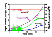
도 4는 실험예 4의 조건으로 구동한 시간에 따른 전압, 전류 및 온도 변화를 나타낸 그래프.
도 5는 실험예 5의 조건으로 구동한 시간에 따른 전압, 전류 및 온도 변화를 나타낸 그래프.
도 6은 상기 실험예 6의 조건으로 구동한 시간에 따른 전압 변화를 나타낸 그래프.
도 7은 실험예 8의 조건으로 구동한 시간에 따른 전압, 전류 및 온도 변화를 나타낸 그래프.
도 8은 실험예 9의 조건으로 구동한 시간에 따른 전압, 전류 및 온도 변화를 나타낸 그래프.
도 9는 실험예 10의 조건으로 구동한 시간에 따른 전압 변화를 나타낸 그래프.
도 10은 실험예 11의 조건으로 구동한 시간에 따른 전압, 전류 및 온도 변화를 나타낸 그래프.1 shows a schematic structure of a fuel cell system of the present invention.
2 is a graph showing a voltage change with time driven under the conditions of Experimental Examples 2 and 3. FIG.
3 is a graph showing a voltage change with time driven under the conditions of Experimental Examples 2 and 3. FIG.
4 is a graph showing changes in voltage, current, and temperature with time driven under the conditions of Experimental Example 4. FIG.
5 is a graph showing changes in voltage, current, and temperature with time driven under the conditions of Experimental Example 5. FIG.
Figure 6 is a graph showing the voltage change with time driven under the conditions of Experimental Example 6.
7 is a graph showing changes in voltage, current, and temperature with time driven under the conditions of Experimental Example 8. FIG.
8 is a graph showing changes in voltage, current, and temperature with time driven under the conditions of Experimental Example 9. FIG.
9 is a graph showing a change in voltage over time driven under the conditions of Experimental Example 10;
10 is a graph showing changes in voltage, current, and temperature with time driven under the conditions of Experimental Example 11. FIG.
이하, 본 발명의 구현예를 상세히 설명하기로 한다. 다만, 이는 예시로서 제시되는 것으로, 이에 의해 본 발명이 제한되지는 않으며 본 발명은 후술할 청구항의 범주에 의해 정의될 뿐이다.Hereinafter, embodiments of the present invention will be described in detail. However, this is presented as an example, by which the present invention is not limited and the present invention is defined only by the scope of the claims to be described later.
본 발명의 일 구현예는 직접 메탄올형 연료 전지 시스템의 저온 시동 방법을 제공하는 것이다.One embodiment of the present invention is to provide a low temperature start-up method of a direct methanol fuel cell system.
본 명세서에 있어서, 스택이란, 막-전극 어셈블리와 세퍼레이터를 포함하는 단위 셀을 의미한다. In the present specification, the stack means a unit cell including a membrane electrode assembly and a separator.
상기 저온 시동 방법은, 스택에 어는점이 외부 온도보다 낮은 농도 이상의 탄화수소 연료 및 산화제를 공급하면서, 정전압 조건으로 스택 온도가 30 내지 80℃에 도달할 때까지 구동시키는 단계를 포함한다.The cold start method includes driving a stack at a constant voltage condition until the stack temperature reaches 30 to 80 ° C. while supplying a hydrocarbon fuel and an oxidant at a freezing point lower than an external temperature.
이하 저온 시동 방법에 대하여 보다 자세하게 설명한다. 본 명세서에서 저온 시동 방법이란, -5 ℃ 이하의 낮은 온도에서 연료 전지 시스템을 구동시킬 수 있는 방법을 의미한다. 특히, 본 발명은 -10 ℃ 이하의 가혹한 환경에서 더욱 효과적이다. 다만, 이 온도 범위는 본 발명을 가장 효과적으로 활용할 수 있는 범위의 온도를 말하며, 이를 벗어나는 범위에 대해 본 발명의 범위를 제한하는 것은 아니다.Hereinafter, the low temperature starting method will be described in more detail. In the present specification, the low temperature start-up method means a method capable of driving the fuel cell system at a low temperature of -5 ° C or lower. In particular, the present invention is more effective in harsh environments below -10 ° C. However, this temperature range refers to the temperature of the range that can utilize the present invention most effectively, and does not limit the scope of the present invention for a range outside of this.
상기 스택을 저온에서 구동시키기 위하여는, 어는점이 외부 온도보다 낮은 농도 이상의 탄화수소 연료를 사용하는 것이 바람직하며, 예를 들어 3 내지 8M 농도의 고농도 탄화수소 연료가 사용될 수 있으며, 이에 제한되는 것은 아니다. 또한, 이와 같이 고농도 탄화수소 연료를 사용하는 경우, 탄화수소 연료가 전해질 막을 투과하여, 애노드 전극에서 캐소드 전극으로 이동하고, 캐소드 전극에서 산화되어 캐소드 촉매의 피독, 연료 효율 감소 및 전극 전위 감소를 야기하는 연료 크로스 오버 문제가 있을 수 있으므로, 메탄올 투과 저감막을 사용하는 것이 바람직하다. 메탄올 투과 저감막에 대해서는 후술하도록 한다.In order to operate the stack at a low temperature, it is preferable to use a hydrocarbon fuel having a freezing point lower than the external temperature, for example, a high concentration hydrocarbon fuel having a concentration of 3 to 8 M may be used, but is not limited thereto. In addition, in the case of using a high concentration hydrocarbon fuel in this way, the hydrocarbon fuel penetrates the electrolyte membrane, moves from the anode electrode to the cathode electrode, and is oxidized at the cathode electrode to cause poisoning of the cathode catalyst, a decrease in fuel efficiency, and a decrease in electrode potential. Since there may be a crossover problem, it is preferable to use a methanol permeation reduction membrane. The methanol permeation reduction membrane will be described later.
상기 정전압 조건은 단위전지 당 0.3 내지 0.5 V에서 실시할 수 있다. 정전압 조건의 전압을 상기와 같은 범위로 하면 DMFC 단위 전지의 출력을 안정적으로 얻을 수 있어 바람직하다.The constant voltage condition may be performed at 0.3 to 0.5 V per unit cell. When the voltage under the constant voltage condition is in the above range, the output of the DMFC unit battery can be obtained stably, which is preferable.
상기 탄화수소 연료와 상기 산화제는 2.5 내지 4λ의 화학양론비 (stoichiometry)로 상기 스택에 공급하는 것이 적절하다.It is appropriate to feed the hydrocarbon fuel and the oxidant to the stack in stoichiometry of 2.5 to 4λ.
상기 탄화수소 연료는 메탄올, 에탄올, 프로판올, 천연 가스 및 이들의 조합으로 이루어진 군에서 선택되는 것을 적절하게 사용할 수 있다. 특히, 상기 탄화수소 연료는 메탄올을 보다 바람직하게 사용할 수 있다.The hydrocarbon fuel may be appropriately selected from the group consisting of methanol, ethanol, propanol, natural gas and combinations thereof. In particular, the hydrocarbon fuel may more preferably use methanol.
상기 산화제는 공기를 적절하게 사용할 수 있다.The oxidant can use air suitably.
또한, 상기 스택은 열적 절연 물질로 코팅되어 있을 수 있다. 이와 같이 스택이 열적 절연 물질로 코팅되어 있으면, 스택 내에서 온도 증가율을 보다 향상시킬 수 있고 스택의 열 손실을 보다 효과적으로 방지할 수 있으며, 스택의 성능을 보다 향상시킬 수 있다.In addition, the stack may be coated with a thermal insulating material. Thus, if the stack is coated with a thermal insulating material, it is possible to further improve the rate of temperature increase in the stack, to more effectively prevent the heat loss of the stack, and to further improve the stack performance.
상기와 같은 방식으로 직접 메탄올 연료전지를 저온 시동하면, 스택의 온도를 적정 출력(전력)을 얻을 수 있는 구동 온도인 30 내지 80℃까지 안정적으로 도달하게 할 수 있다.When the methanol fuel cell is directly started at a low temperature in the above manner, the stack temperature can be stably reached to 30 to 80 ° C., which is a driving temperature at which an appropriate output (power) can be obtained.
스택 온도가 상기 범위로 증가하는 것은, 연료 전지 시스템의 스택의 전기화학적 반응에 의하여 전기를 발생시키면서 발생되는 열에 의한 것인데, 상기와 같은 방식을 적용할 경우 빠른 시간 내에 시스템의 열화 없이 안정적으로 스택의 온도를 적정 구동 온도 범위까지 상승시킬 수 있다.The increase in the stack temperature to the above range is caused by the heat generated while generating electricity by the electrochemical reaction of the stack of the fuel cell system. When the above method is applied, the stack temperature is stably maintained without deterioration of the system. The temperature can be raised to the appropriate drive temperature range.
본 발명에서, 상기 막-전극 어셈블리는 서로 대향하여 위치하는 애노드 전극과 캐소드 전극, 및 이 애노드 전극과 캐소드 전극 사이에 위치하는 전해질 막을 포함하는 막-전극 어셈블리를 포함한다. 이하, 막-전극 어셈블리의 구조에 대하여 설명하기로 한다.In the present invention, the membrane-electrode assembly includes a membrane-electrode assembly including an anode electrode and a cathode electrode positioned opposite each other, and an electrolyte membrane positioned between the anode electrode and the cathode electrode. Hereinafter, the structure of the membrane-electrode assembly will be described.
상기 전해질 막으로는 메탄올 투과 저감막을 사용하는데, 메탄올 투과 저감막이란 이온전도도가 0.1S/cm 이상이고 상대선택성이 5 내지 200인 전해질 막을 말한다. 여기서, 상대선택성이란 [상기 전해질 막의 선택성/나피온 전해질 막의 선택성]을 말하며, 선택성이란 [이온전도도/메탄올 투과율]을 말한다. A methanol permeation reduction membrane is used as the electrolyte membrane, and a methanol permeation reduction membrane refers to an electrolyte membrane having an ion conductivity of 0.1 S / cm or more and a relative selectivity of 5 to 200. Here, relative selectivity refers to [selectivity of the electrolyte membrane / selectivity of Nafion electrolyte membrane], and selectivity refers to [ion conductivity / methanol transmittance].
메탄올이 연료극에서 공기극으로 전해질 막을 투과하여 넘어가면 공기극에서 산소와 직접 만나서 산화함으로써 이른바 혼합전위 (mixed potential)에 의해서 전압 손실이 생기고, 공기극의 촉매를 피독시켜서 성능을 저하시킬 뿐만 아니라 연료의 효율도 저하시키는 결과를 초래한다. 즉, 고농도의 메탄올을 DMFC에 적용하면 성능이 저하되고 약 5M 이상이 되면, 거의 운전이 불가능해진다. When methanol passes through the electrolyte membrane from the anode to the cathode, it meets and oxidizes directly with oxygen at the cathode, resulting in a voltage loss due to the mixed potential, and poisoning the catalyst of the cathode to deteriorate performance and reduce fuel efficiency. Results in deterioration. In other words, when a high concentration of methanol is applied to the DMFC, the performance decreases, and when about 5 M or more, operation is almost impossible.
본 발명에서는 저온 조건 하에서의 안정적인 시동을 위하여 3 내지 8M의 메탄올 연료를 사용하므로, 충분한 수소 이온전도성을 가지며 메탄올 크로스오버를 저감시킬 수 있도록 위와 같은 물성을 갖는 메탄올 투과 저감막을 사용한다.In the present invention, since 3 to 8 M of methanol fuel is used for stable starting under low temperature conditions, a methanol permeation reducing membrane having the above properties is used to have sufficient hydrogen ion conductivity and to reduce methanol crossover.
상기 메탄올 투과 저감막으로는 예를 들어 위와 같은 물성을 갖는 고분자 전해질 막 및 탄화수소 전해질 막이 사용될 수 있다.As the methanol permeation reducing membrane, for example, a polymer electrolyte membrane and a hydrocarbon electrolyte membrane having the above properties may be used.
고분자 전해질 막은 예를 들어 측쇄에 술폰산기, 카르복실산기, 인산기, 포스포닌산기 및 이들의 유도체로 이루어진 군에서 선택되는 양이온 교환기를 갖고 있는 고분자 수지로 제조될 수 있다.The polymer electrolyte membrane can be made of a polymer resin having, for example, a cation exchange group selected from the group consisting of sulfonic acid groups, carboxylic acid groups, phosphoric acid groups, phosphonic acid groups and derivatives thereof in the side chain.
상기 고분자 수지의 대표적인 예로는 플루오르계 고분자, 벤즈이미다졸계 고분자, 폴리이미드계 고분자, 폴리에테르이미드계 고분자, 폴리페닐렌술파이드계 고분자, 폴리술폰계 고분자, 폴리에테르술폰계 고분자, 폴리에테르케톤계 고분자, 폴리에테르-에테르케톤계 고분자 또는 폴리페닐퀴녹살린계 고분자 중에서 선택되는 1종 이상을 포함할 수 있다. 더 바람직하게는 폴리(퍼플루오로술폰산)(일반적으로 나피온으로 시판됨), 폴리(퍼플루오로카르복실산), 술폰산기를 포함하는 테트라플루오로에틸렌과 플루오로비닐에테르의 공중합체, 탈불소화된 황화 폴리에테르케톤, 아릴 케톤, 폴리[(2,2'-m-페닐렌)-5,5'-바이벤즈이미다졸][poly(2,2'-(m-phenylene)-5,5'-bibenzimidazole] 또는 폴리(2,5-벤즈이미다졸) 중에서 선택되는 1종 이상을 들 수 있다.Representative examples of the polymer resin include a fluorine polymer, a benzimidazole polymer, a polyimide polymer, a polyetherimide polymer, a polyphenylene sulfide polymer, a polysulfone polymer, a polyether sulfone polymer and a polyether ketone It may include one or more selected from polymers, polyether-etherketone-based polymers or polyphenylquinoxaline-based polymers. More preferably poly (perfluorosulfonic acid) (generally marketed as Nafion), poly (perfluorocarboxylic acid), copolymers of tetrafluoroethylene and fluorovinyl ethers containing sulfonic acid groups, defluorination Sulfide polyether ketones, aryl ketones, poly [(2,2'-m-phenylene) -5,5'-bibenzimidazole] [poly (2,2 '-(m-phenylene) -5,5 '-bibenzimidazole] or poly (2,5-benzimidazole) may be mentioned.
탄화수소 전해질 막으로는 수소 이온 전도성을 가지는 탄화수소 전해질 막이 사용될 수 있는데, 여기서 수소 이온 전도성기의 예로는 술폰산기, 카르복실산기, 인산기, 포스포닌산기 또는 이들의 조합을 들 수 있다.As the hydrocarbon electrolyte membrane, a hydrocarbon electrolyte membrane having hydrogen ion conductivity may be used, and examples of the hydrogen ion conductive group may include a sulfonic acid group, a carboxylic acid group, a phosphoric acid group, a phosphonic acid group, or a combination thereof.
상기 탄화수소 전해질 막의 탄화수소는 폴리에테르에테르케톤, 폴리프로필렌 옥사이드, 폴리아크릴산, 폴리아릴렌에테르 또는 이들의 조합을 들 수 있다.The hydrocarbon of the hydrocarbon electrolyte membrane may include polyether ether ketone, polypropylene oxide, polyacrylic acid, polyarylene ether, or a combination thereof.
상기 캐소드 전극 및 애노드 전극은 전극 기재와 촉매층을 포함한다.The cathode electrode and the anode electrode include an electrode substrate and a catalyst layer.
상기 촉매층에서 촉매로는 연료 전지의 반응에 참여하여, 촉매로 사용가능한 것은 어떠한 것도 사용할 수 있으며, 그 대표적인 예로 백금계 촉매를 사용할 수 있다. 상기 백금계 촉매로는 백금, 루테늄, 오스뮴, 백금-루테늄 합금, 백금-오스뮴 합금, 백금-팔라듐 합금 또는 백금-M 합금(M은 Ga, Ti, V, Cr, Mn, Fe, Co, Ni, Cu, Zn, Sn, Mo, W, Rh 및 Ru로 이루어진 군으로부터 선택되는 1종 이상의 전이 금속) 중에서 선택되는 1종 이상의 촉매를 사용할 수 있다. 이와 같이 애노드 전극과 캐소드 전극은 동일한 물질을 사용하여도 무방하나, 직접 산화 연료 전지에서는 애노드 전극 반응 중에서 발생되는 CO에 의한 촉매 피독 현상이 발생함에 따라 이를 방지하기 위하여, 백금-루테늄 합금 촉매가 애노드 전극 촉매로는 보다 바람직하다. 구체적인 예로는 Pt, Pt/Ru, Pt/W, Pt/Ni, Pt/Sn, Pt/Mo, Pt/Pd, Pt/Fe, Pt/Cr, Pt/Co, Pt/Ru/W, Pt/Ru/Mo, Pt/Ru/V, Pt/Fe/Co, Pt/Ru/Rh/Ni 및 Pt/Ru/Sn/W으로 이루어진 군에서 선택되는 1종 이상의 것을 사용할 수 있다.In the catalyst layer, any catalyst that can be used as a catalyst may be used as a catalyst in the reaction of a fuel cell, and a platinum-based catalyst may be used as a representative example. The platinum-based catalyst may be platinum, ruthenium, osmium, platinum-ruthenium alloy, platinum-osmium alloy, platinum-palladium alloy or platinum-M alloy (M is Ga, Ti, V, Cr, Mn, Fe, Co, Ni, At least one catalyst selected from the group consisting of Cu, Zn, Sn, Mo, W, Rh and Ru). As described above, the anode electrode and the cathode electrode may use the same material, but in order to prevent the catalyst poisoning caused by CO generated during the anode electrode reaction in the direct oxidation fuel cell, a platinum-ruthenium alloy catalyst is used as the anode. It is more preferable as an electrode catalyst. Specific examples include Pt, Pt / Ru, Pt / W, Pt / Ni, Pt / Sn, Pt / Mo, Pt / Pd, Pt / Fe, Pt / Cr, Pt / Co, Pt / Ru / W, Pt / Ru One or more selected from the group consisting of / Mo, Pt / Ru / V, Pt / Fe / Co, Pt / Ru / Rh / Ni, and Pt / Ru / Sn / W can be used.
또한 이러한 금속 촉매는 금속 촉매 자체(black)로 사용할 수도 있고, 담체에 담지시켜 사용할 수도 있다. 이 담체로는 흑연, 덴카 블랙, 케첸 블랙, 아세틸렌 블랙, 카본 나노 튜브, 카본 나노 파이버, 카본 나노 와이어, 카본 나노 볼 또는 활성 탄소 등의 탄소계 물질을 사용할 수도 있고, 또는 알루미나, 실리카, 지르코니아, 티타니아 등의 무기물 미립자를 사용할 수도 있으나, 일반적으로 탄소계 물질이 사용되고 있다. 담체에 담지된 귀금속을 촉매로 사용하는 경우에는 상용화된 시판되는 것을 사용할 수도 있고, 또한 담체에 귀금속을 담지시켜 제조하여 사용할 수도 있다. 담체에 귀금속을 담지시키는 공정은 당해 분야에서 널리 알려진 내용이므로 본 명세서에서 자세한 설명은 생략하여도, 당해 분야에 종사하는 사람들에게 쉽게 이해될 수 있는 내용이다.In addition, such a metal catalyst may be used as the metal catalyst (black) itself, or may be supported on a carrier. As the carrier, carbonaceous materials such as graphite, denka black, ketjen black, acetylene black, carbon nanotubes, carbon nanofibers, carbon nanowires, carbon nanoballs or activated carbon may be used, or alumina, silica, zirconia, Inorganic fine particles such as titania may be used, but carbon-based materials are generally used. In the case of using the noble metal supported on the carrier as a catalyst, a commercially available commercially available product may be used, or the noble metal supported on the carrier may be prepared and used. Since the process of supporting the precious metal on the carrier is well known in the art, detailed descriptions thereof will be readily understood by those skilled in the art even if the detailed description is omitted.
상기 촉매층은 또한 촉매층의 접착력 향상 및 수소 이온의 전달을 위하여 바인더 수지를 더 포함할 수도 있다. The catalyst layer may further include a binder resin for improving the adhesion of the catalyst layer and the transfer of hydrogen ions.
상기 바인더 수지로는 수소 이온 전도성을 갖는 고분자 수지를 사용하는 것이 바람직하고, 보다 바람직하게는 측쇄에 술폰산기, 카르복실산기, 인산기, 포스포닌산기 및 이들의 유도체로 이루어진 군에서 선택되는 양이온 교환기를 갖고 있는 고분자 수지는 모두 사용할 수 있다. 바람직하게는 플루오르계 고분자, 벤즈이미다졸계 고분자, 폴리이미드계 고분자, 폴리에테르이미드계 고분자, 폴리페닐렌술파이드계 고분자, 폴리술폰계 고분자, 폴리에테르술폰계 고분자, 폴리에테르케톤계 고분자, 폴리에테르-에테르케톤계 고분자 또는 폴리페닐퀴녹살린계 고분자 중에서 선택되는 1종 이상의 수소 이온 전도성 고분자를 포함할 수 있고, 보다 바람직하게는 폴리(퍼플루오로술폰산), 폴리(퍼플루오로카르복실산), 술폰산기를 포함하는 테트라플루오로에틸렌과 플루오로비닐에테르의 공중합체, 황화 폴리에테르케톤, 아릴 케톤, 폴리(2,2'-m-페닐렌)-5,5'-바이벤즈이미다졸[poly(2,2'-m-phenylene)-5,5'-bibenzimidazole] 또는 폴리(2,5-벤즈이미다졸) 중에서 선택되는 1종 이상의 수소 이온 전도성 고분자를 포함하는 것을 사용할 수 있다. It is preferable to use a polymer resin having hydrogen ion conductivity as the binder resin, more preferably a cation exchange group selected from the group consisting of sulfonic acid group, carboxylic acid group, phosphoric acid group, phosphonic acid group and derivatives thereof in the side chain. Any polymer resin which has can be used. Preferably, a fluorine polymer, a benzimidazole polymer, a polyimide polymer, a polyetherimide polymer, a polyphenylene sulfide polymer, a polysulfone polymer, a polyether sulfone polymer, a polyether ketone polymer, a polyether One or more hydrogen ion conductive polymers selected from ether ketone polymers or polyphenylquinoxaline polymers, more preferably poly (perfluorosulfonic acid), poly (perfluorocarboxylic acid), Copolymers of tetrafluoroethylene and fluorovinyl ether containing sulfonic acid groups, sulfide polyether ketones, aryl ketones, poly (2,2'-m-phenylene) -5,5'-bibenzimidazoles [poly ( 2,2'-m-phenylene) -5,5'-bibenzimidazole] or poly (2,5-benzimidazole) may be used including one or more hydrogen ion conductive polymers.
상기 수소 이온 전도성 고분자는 측쇄 말단의 양이온 교환기에서 H를 Na, K, Li, Cs 또는 테트라부틸암모늄으로 치환할 수도 있다. 측쇄 말단의 이온 교환기에서 H를 Na으로 치환하는 경우에는 촉매 조성물 제조시 NaOH를, 테트라부틸암모늄으로 치환하는 경우에는 테트라부틸암모늄 하이드록사이드를 사용하여 치환하며, K, Li 또는 Cs도 적절한 화합물을 사용하여 치환할 수 있다. 이 치환 방법은 당해 분야에 널리 알려진 내용이므로 본 명세서에서 자세한 설명은 생략하기로 한다.The hydrogen ion conductive polymer may replace H with Na, K, Li, Cs or tetrabutylammonium in a cation exchanger at the side chain terminal. In case of replacing H with Na in the side chain terminal ion exchanger, NaOH is substituted for the preparation of the catalyst composition, and tetrabutylammonium hydroxide is substituted for tetrabutylammonium, and K, Li or Cs may be substituted with appropriate compounds. It can be substituted using. Since this substitution method is well known in the art, detailed description thereof will be omitted.
상기 바인더 수지는 단일물 또는 혼합물 형태로 사용가능하며, 또한 선택적으로 고분자 전해질 막과의 접착력을 보다 향상시킬 목적으로 비전도성 화합물과 함께 사용될 수도 있다. 그 사용량은 사용 목적에 적합하도록 조절하여 사용하는 것이 바람직하다. The binder resin may be used in the form of a single substance or a mixture, and may also be optionally used with a nonconductive compound for the purpose of further improving adhesion to the polymer electrolyte membrane. It is preferable to adjust the usage-amount so that it may be suitable for a purpose of use.
상기 비전도성 화합물로는 폴리테트라플루오로에틸렌(PTFE), 테트라 플루오로에틸렌-헥사플루오르프로필렌 공중합체(FEP), 테트라플루오로에틸렌- 퍼플루오로 알킬비닐에테르 공중합체(PFA), 에틸렌/테트라플루오로에틸렌 (ethylene/tetrafluoroethylene(ETFE)), 에틸렌클로로트리플루오로-에틸렌 공중합체(ECTFE), 폴리비닐리덴플루오라이드, 폴리비닐리덴플루오라이드-헥사플루오로프로필렌의 코폴리머(PVdF-HFP), 도데실벤젠술폰산 및 소르비톨(Sorbitol)로 이루어진 군에서 선택된 1종 이상의 것이 보다 바람직하다.Examples of the non-conductive compound include polytetrafluoroethylene (PTFE), tetrafluoroethylene-hexafluoropropylene copolymer (FEP), tetrafluoroethylene-perfluoro alkyl vinyl ether copolymer (PFA), and ethylene / tetrafluoro Ethylene / tetrafluoroethylene (ETFE), ethylenechlorotrifluoro-ethylene copolymer (ECTFE), polyvinylidene fluoride, copolymer of polyvinylidene fluoride-hexafluoropropylene (PVdF-HFP), dode At least one selected from the group consisting of silbenzenesulfonic acid and sorbitol is more preferred.
상기 전극 기재는 전극을 지지하는 역할을 하면서 촉매층으로 연료 및 산화제를 확산시켜 촉매층으로 연료 및 산화제가 쉽게 접근할 수 있는 역할을 한다. 상기 전극 기재로는 도전성 기재를 사용하며 그 대표적인 예로 탄소 페이퍼(carbon paper), 탄소 천(carbon cloth), 탄소 펠트(carbon felt) 또는 금속천(섬유 상태의 금속으로 구성된 다공성의 필름 또는 고분자 섬유로 형성된 천의 표면에 금속 필름이 형성된 것을 말함)이 사용될 수 있으나, 이에 한정되는 것은 아니다. The electrode substrate plays a role of supporting the electrode and diffuses the fuel and the oxidant to the catalyst layer, thereby serving to easily access the fuel and the oxidant to the catalyst layer. The electrode substrate is a conductive substrate, and representative examples thereof include carbon paper, carbon cloth, carbon felt, or metal cloth (porous film or polymer fiber composed of metal in a fibrous state). The metal film is formed on the surface of the formed cloth) may be used, but is not limited thereto.
또한 상기 전극 기재는 불소 계열 수지로 발수 처리한 것을 사용하는 것이 연료 전지의 구동시 발생되는 물에 의하여 반응물 확산 효율이 저하되는 것을 방지할 수 있어 바람직하다. 상기 불소 계열 수지로는 폴리테트라플루오로에틸렌, 폴리비닐리덴 플루오라이드, 폴리헥사플루오로프로필렌, 폴리퍼플루오로알킬비닐에테르, 폴리퍼플루오로술포닐플루오라이드알콕시비닐 에테르, 플루오리네이티드 에틸렌 프로필렌(Fluorinated ethylene propylene), 폴리클로로트리플루오로에틸렌 또는 이들의 코폴리머를 사용할 수 있다. In addition, it is preferable to use a water-repellent treatment with a fluorine-based resin as the electrode base material because it can prevent the reactant diffusion efficiency from being lowered by water generated when the fuel cell is driven. Examples of the fluorine-based resin include polytetrafluoroethylene, polyvinylidene fluoride, polyhexafluoropropylene, polyperfluoroalkyl vinyl ether, polyperfluorosulfonyl fluoride alkoxy vinyl ether, and fluorinated ethylene propylene ( Fluorinated ethylene propylene), polychlorotrifluoroethylene or copolymers thereof can be used.
또한, 상기 전극 기재에서의 반응물 확산 효과를 증진시키기 위한 미세 기공층(microporous layer)을 더욱 포함할 수도 있다. 이 미세 기공층은 일반적으로 입경이 작은 도전성 분말, 예를 들어 탄소 분말, 카본 블랙, 아세틸렌 블랙, 활성 탄소, 카본 파이버, 플러렌(fullerene), 카본 나노 튜브, 카본 나노 와이어, 카본 나노 혼(carbon nano-horn) 또는 카본 나노 링(carbon nano ring)을 포함할 수 있다. In addition, a microporous layer may be further included to enhance the reactant diffusion effect in the electrode substrate. These microporous layers are generally conductive powders having a small particle diameter, such as carbon powder, carbon black, acetylene black, activated carbon, carbon fiber, fullerene, carbon nanotubes, carbon nanowires, and carbon nanohorns. -horn or carbon nano ring.
상기 미세 기공층은 도전성 분말, 바인더 수지 및 용매를 포함하는 조성물을 상기 전극 기재에 코팅하여 제조된다. 상기 바인더 수지로는 폴리테트라플루오로에틸렌, 폴리비닐리덴플루오라이드, 폴리헥사플루오로프로필렌, 폴리퍼플루오로알킬비닐에테르, 폴리퍼플루오로술포닐플루오라이드, 알콕시비닐 에테르, 폴리비닐알코올, 셀룰로오스아세테이트 또는 이들의 코폴리머 등이 바람직하게 사용될 수 있다. 상기 용매로는 에탄올, 이소프로필알코올, n-프로필알코올, 부틸알코올 등과 같은 알코올, 물, 디메틸아세트아마이드, 디메틸술폭사이드, N-메틸피롤리돈, 테트라하이드로퓨란 등이 바람직하게 사용될 수 있다. 코팅 공정은 조성물의 점성에 따라 스크린 프린팅법, 스프레이 코팅법 또는 닥터 블레이드를 이용한 코팅법 등이 사용될 수 있으며, 이에 한정되는 것은 아니다.The microporous layer is prepared by coating a composition comprising a conductive powder, a binder resin and a solvent on the electrode substrate. The binder resin may be polytetrafluoroethylene, polyvinylidene fluoride, polyhexafluoropropylene, polyperfluoroalkyl vinyl ether, polyperfluorosulfonyl fluoride, alkoxy vinyl ether, polyvinyl alcohol, cellulose acetate Or copolymers thereof and the like can be preferably used. As the solvent, alcohols such as ethanol, isopropyl alcohol, n-propyl alcohol, butyl alcohol, water, dimethylacetamide, dimethyl sulfoxide, N-methylpyrrolidone, tetrahydrofuran, etc. may be preferably used. The coating process may be screen printing, spray coating, or coating using a doctor blade according to the viscosity of the composition, but is not limited thereto.
본 발명에 있어서, 연료 전지 시스템은 상기 스택과, 연료 공급부 및 산화제 공급부를 포함한다.In the present invention, a fuel cell system includes the stack, a fuel supply part and an oxidant supply part.
상기 연료 공급부는 연료를 상기 전기 발생부로 공급하는 역할을 하며, 상기 산화제 공급부는 산소 또는 공기와 같은 산화제를 상기 전기 발생부로 공급하는 역할을 한다.The fuel supply unit serves to supply fuel to the electricity generation unit, and the oxidant supply unit serves to supply an oxidant such as oxygen or air to the electricity generation unit.
본 발명의 연료 전지 시스템의 개략적인 구조를 도 1에 나타내었으며, 이를 참조로 보다 상세하게 설명하면 다음과 같다. 도 1에 나타낸 구조는 연료 및 산화제를 펌프를 사용하여 전기 발생부로 공급하는 시스템을 나타내었으나, 본 발명의 연료 전지 시스템이 이러한 구조에 한정되는 것은 아니며, 펌프를 사용하지 않는 확산 방식을 이용하는 연료 전지 시스템 구조에 사용할 수도 있음은 당연한 일이다.A schematic structure of the fuel cell system of the present invention is shown in FIG. 1, which will be described in more detail with reference to the following. Although the structure shown in FIG. 1 shows a system for supplying fuel and oxidant to an electric generator using a pump, the fuel cell system of the present invention is not limited to such a structure, and a fuel cell using a diffusion method without using a pump is shown. Of course, it can also be used for system architecture.
본 발명의 연료 전지 시스템(1)은 연료의 산화 반응과 산화제의 환원 반응을 통해 전기 에너지를 발생시키는 적어도 하나의 전기 발생부(3)와, 상기한 연료를 공급하는 연료 공급부(5)와, 산화제를 상기 전기 발생부(3)로 공급하는 산화제 공급부(7)를 포함하여 구성된다.The
또한 상기 연료를 공급하는 연료 공급부(5)는 연료를 저장하는 연료 탱크(9), 연료 탱크(9)에 연결 설치되는 연료 펌프(11)를 구비할 수 있다. 상기한 연료 펌프(11)는 소정의 펌핑력에 의해 연료 탱크(9)에 저장된 연료를 배출시키는 기능을 하게 된다.In addition, the
상기 전기 발생부(3)로 산화제를 공급하는 산화제 공급부(7)는 소정의 펌핑력으로 산화제를 흡입하는 적어도 하나의 산화제 펌프(13)를 구비한다.The
상기 전기 발생부(3)는 연료와 산화제를 산화 및 환원 반응시키는 막-전극 어셈블리(17)와 이 막-전극 어셈블리의 양측에 연료와 산화제를 공급하기 위한 세퍼레이터(19,19')로 구성되며, 이러한 전기 발생부(3)가 적어도 하나 모여 스택(15)을 구성한다. The
이하 본 발명의 바람직한 실시예 및 비교예를 기재한다. 그러나 하기한 실시예는 본 발명의 바람직한 일 실시예일뿐 본 발명이 하기한 실시예에 의해 한정되는 것은 아니다. Hereinafter, preferred examples and comparative examples of the present invention are described. However, the following examples are only preferred embodiments of the present invention and the present invention is not limited to the following examples.
[실시예][Example]
모든 실험은 동일한 영하 이하의 온도를 유지하기 위하여, 온도 및 습도를 조절할 수 있는 환경 챔버(JEIO-Tech, TH-G 180, 한국)에서 실시하였다.All experiments were conducted in an environmental chamber (JEIO-Tech, TH-G 180, Korea) that can control temperature and humidity to maintain the same sub-zero temperature.
(실험예 1): 스택의 제조Experimental Example 1 Manufacture of Stack
PtRu/C 애노드 촉매(HISPEC 12100, Johnson Matthey, UK)의 로딩량은 2.0mg/㎠으로 나피온/H2O/2-프로판올 바인더액을 혼합하여 애노드 전극용 촉매 조성물을 제조하였다. 이 촉매 조성물을 5 중량% 폴리테트라플루오로에틸렌으로 처리된 탄소지 전극 기재(TGP-H060, Toray carbon, 일본)에 도포하여 애노드 전극을 제조하였다. 애노드 전극에서, PtRu/C 애노드 촉매의 로딩량은 2.0mg/㎠이었다. A loading amount of the PtRu / C anode catalyst (HISPEC 12100, Johnson Matthey, UK) was 2.0 mg / cm 2 to mix Nafion / H 2 O / 2-propanol binder liquid to prepare a catalyst composition for the anode electrode. The catalyst composition was applied to a carbon paper electrode substrate (TGP-H060, Toray carbon, Japan) treated with 5% by weight polytetrafluoroethylene to prepare an anode electrode. At the anode electrode, the loading of the PtRu / C anode catalyst was 2.0 mg /
아울러, 캐소드용 기체 확산층으로는 미세기공층을 갖는 SGL 탄소지(®SIGRACET GDL 25BC, SGL Carbon 독일)을 사용하였다. 이때 Pt/C 캐소드 촉매(HISPEC 12100, Johnson Matthey, UK) 로딩량은 백금 중량 기준으로 2.0 mg/㎠으로 하였다. In addition, SGL carbon paper ( ® SIGRACET GDL 25BC, SGL Carbon Germany) having a microporous layer was used as the gas diffusion layer for the cathode. At this time, the loading amount of Pt / C cathode catalyst (HISPEC 12100, Johnson Matthey, UK) was 2.0 mg /
상기 각 전극의 활성 전극 면적은 30㎠이었다. The active electrode area of each electrode was 30
제조된 애노드 전극 및 캐소드 전극과 두께 20㎛인 탄화수소 전해질 막(PF DM-1-20-HB-o, 폴리퓨얼사)을 이용하여 Carver Laboratory Press(Carver, Model M, USA)를 사용하여 150℃에서 1분 동안 50kg 미만의 압력하에서 핫-프레스하여, 막-전극 어셈블리를 제조하였다.150 ° C. using a Carver Laboratory Press (Carver, Model M, USA) using the prepared anode electrode and cathode electrode and a hydrocarbon electrolyte membrane (PF DM-1-20-HB-o, Polyfuel) having a thickness of 20 μm. The membrane-electrode assembly was prepared by hot-pressing under a pressure of less than 50 kg for 1 minute at.
상기 막-전극 어셈블리와 그라파이트 바이폴라 플레이트를 포함하는 단위 셀을 10개 적층하여 스택을 제조하였다.A stack was prepared by stacking 10 unit cells including the membrane-electrode assembly and the graphite bipolar plate.
(실험예 2)(Experimental Example 2)
실험예 1에서 제조된 스택과, 3M의 메탄올을 각각 챔버 내에서 -5℃로 유지한 후, 상기 스택에 -5℃로 유지된 3M 메탄올과 공기를 각각 3.0, 3.5λ의 화학양론비로 주입하고, 0.5A의 정전류 조건으로 구동하였다. The stack prepared in Experimental Example 1 and 3M methanol were maintained at -5 ° C in the chamber, respectively, and 3M methanol and air maintained at -5 ° C were injected into the stack at stoichiometric ratios of 3.0 and 3.5λ, respectively. , It was driven under a constant current condition of 0.5A.
(실험예 3)Experimental Example 3
0.5A의 정전류 조건 대신 1.0A의 정전류 조건으로 구동한 것을 제외하고는 상기 실험예 2와 동일하게 실시하였다.The same procedure as in
상기 실험예 2 및 3의 조건으로 구동한 시간에 따른, 전압 변화를 도 2에나타내었고, 온도 변화를 도 3에 나타내었다.The voltage change with time driven under the conditions of Experimental Examples 2 and 3 is shown in FIG. 2, and the temperature change is shown in FIG. 3.
도 2에 나타낸 것과 같이, 0.5A 및 1.0A의 전류를 -5℃에서 스택에 공급하면, 스택 전압은 순간적으로 0.5A 전류를 공급한 실험예 2의 경우에는 약 8.0V에서 3.38V로 저하되고, 1.0A 전류를 공급한 실험예 3의 경우에는 약 8.0V에서 2.16V로 저하되고, 30분간 5.14V 및 4.63V로 점진적으로 회복됨을 알 수 있다.As shown in Fig. 2, when the currents of 0.5A and 1.0A were supplied to the stack at -5 ° C, the stack voltage was lowered from about 8.0V to 3.38V in the case of Experimental Example 2 which supplied the 0.5A current instantaneously. , Experimental Example 3, which was supplied with a 1.0A current, is reduced from about 8.0V to 2.16V, and gradually recovered to 5.14V and 4.63V for 30 minutes.
결과적으로 출력 특성은 -5℃에서 1.7W 및 2.16W의 낮은 출력으로 시작하여, 약 30분 후, 2.57W 및 4.43W로 각각 증가하였음을 알 수 있다.As a result, it can be seen that the output characteristics started with low outputs of 1.7 W and 2.16 W at −5 ° C., and increased to 2.57 W and 4.43 W after about 30 minutes, respectively.
또한, 도 3에 나타낸 것과 같이, 0.5A 및 1.0A의 전류를 -5℃에서 스택에 인가하면, 스택 온도는 각각 34℃(실험예 2) 및 39℃(실험예 3)로 증가함을 알 수 있다. 이러한 출력 증가는 스택 온도 증가 때문인 것으로 생각된다. 또한, 외부 열원이 없기에, 이 온도 증가는 내부 발열 반응 때문임을 예측할 수 있다. In addition, as shown in FIG. 3, when 0.5A and 1.0A of current were applied to the stack at -5 ° C, the stack temperature was increased to 34 ° C (Experimental Example 2) and 39 ° C (Experimental Example 3), respectively. Can be. This increase in power is thought to be due to an increase in stack temperature. In addition, since there is no external heat source, it can be predicted that this temperature increase is due to an internal exothermic reaction.
(실험예 4)Experimental Example 4
0.5A의 정전류 조건 대신, 0.5A에서 4A로 단계적으로 증가시키면서, 구동시킨 것을 제외하고는 상기 실험예 2와 동일하게 실시하였다. Instead of the constant current condition of 0.5A, it was carried out in the same manner as in
실험예 4의 조건으로 구동한 시간에 따른 전압, 전류 및 온도 변화를 측정하여, 그 결과를 도 4에 나타내었다. 도 4에 나타낸 것과 같이, 전류를 변화시키면서 구동시킨 경우에는 전압이 초기에 급격하게 저하되다가 서서히 증가하기는 하나, 여전히 낮은 전압을 나타내고 있다. Voltage, current, and temperature change with time driven under the conditions of Experimental Example 4 were measured, and the results are shown in FIG. 4. As shown in Fig. 4, when driven while changing the current, the voltage suddenly decreases initially and then gradually increases, but still shows a low voltage.
또한, 스택 온도 또한, 20분을 구동하여도, 약 20℃ 정도로, 도 3에 나타낸 결과와 비교하여 온도 증가가 크지 않음을 알 수 있다In addition, even if the stack temperature is also driven for 20 minutes, it can be seen that the temperature increase is not large compared to the result shown in FIG.
또한, 도 4에 나타낸 것과 같이, 스택의 온도가 증가할수록 스택의 전압은 어느 정도 유지되는 상태(steady-state)를 나타내고 있으며, 이는 영하 이하의 낮은 온도에서 스택의 전압은 스택 온도에 의해 크게 영향을 받음을 알 수 있다. In addition, as shown in FIG. 4, as the temperature of the stack increases, the voltage of the stack shows a steady-state, which means that at low temperatures below zero, the voltage of the stack is greatly influenced by the stack temperature. It can be seen that.
(실험예 5)Experimental Example 5
0.5A의 정전류 조건 대신, 4V의 정전압으로 구동시킨 것을 제외하고는 상기 실험예 2와 동일하게 실시하였다. Instead of a constant current condition of 0.5A, it was carried out in the same manner as in Experimental Example 2 except that it was driven at a constant voltage of 4V.
실험예 5의 조건으로 구동한 시간에 따른 전압, 전류 및 온도 변화를 측정하여, 그 결과를 도 5에 나타내었다. 도 5에 나타낸 것과 같이, 초기에는 약 0.3A의 매우 낮은 전류가 얻어졌으나, 스택 온도가 증가하면서, 전류가 향상됨을 알 수 있다. 결과적으로 스택 온도는 -5℃에서 52℃로 증가하고, 출력은 9.7W가 나타났음을 알 수 있다.Voltage, current, and temperature change with time driven under the conditions of Experimental Example 5 were measured, and the results are shown in FIG. 5. As shown in FIG. 5, a very low current of about 0.3 A was initially obtained, but it can be seen that as the stack temperature increases, the current improves. As a result, the stack temperature increased from -5 ° C to 52 ° C and the output showed 9.7W.
도 4 및 도 5에 나타낸 결과로부터, 스택 온도가 실온에 도달하고 나면, 스택의 성능이 유지됨을 알 수 있다. 또한, 정전압 모드로 구동시킨 실험예 5의 경우, 출력 특성이 약 9.7W로, 정전류 모드로 구동시킨 경우 출력 특성 8.2W보다 높게 나타났음을 알 수 있다.It can be seen from the results shown in FIGS. 4 and 5 that once the stack temperature reaches room temperature, the stack performance is maintained. In addition, in Experimental Example 5 driven in the constant voltage mode, the output characteristic is about 9.7W, and when driven in the constant current mode, it can be seen that the output characteristic is higher than 8.2W.
(실험예 6)Experimental Example 6
실험예 1에서 제조된 스택과, 5M의 메탄올을 각각 챔버 내에서 -10℃로 유지한 후, 상기 스택에 -10℃로 유지된 5M 메탄올과 공기를 각각 3.0, 3.5λ의 화학양론비로 주입하고, 0.5A의 정전류 조건으로 구동하였다. The stack prepared in Experimental Example 1 and 5 M methanol were maintained at -10 ° C. in the chamber, respectively, and 5 M methanol and air maintained at −10 ° C. were injected into the stack at stoichiometric ratios of 3.0 and 3.5λ, respectively. , It was driven under a constant current condition of 0.5A.
상기 실험예 6의 조건으로 구동한 시간에 따른, 전압 변화를 도 6에 나타내었다. 초기에는 전압이 2.69V로 약간 저하되었으며, 이는 -5℃에서 일어난 전압 강하 3.38V보다 크나, 곧 전압이 다시 상승하여, 5.12V로 증가하였음을 알 수 있다. 또한, 도 6에 나타낸 것과 같이, 스택 온도는 51℃까지 매우 높게 증가하였으며, 이는 5M 메탄올 사용으로 인한 크로스오버 때문인 것으로 예상된다.The voltage change with time driven under the conditions of Experimental Example 6 is shown in FIG. 6. Initially, the voltage slightly decreased to 2.69V, which is greater than the voltage drop of 3.38V occurring at -5 ° C, but the voltage rose again and increased to 5.12V. In addition, as shown in FIG. 6, the stack temperature increased very high up to 51 ° C., which is expected due to the crossover due to the use of 5M methanol.
(실험예 7)Experimental Example 7
1.0A의 정전류 조건으로 구동한 것을 제외하고는 상기 실험예 6과 동일하게 실시하였다.Except for driving under a constant current condition of 1.0A was carried out in the same manner as in
상기 실험예 7의 조건으로 구동시킨 경우, 전압이 0.1V 미만으로 너무 낮아, 더 이상의 실험이 무의미하였다.When driven under the conditions of Experimental Example 7, the voltage was too low, less than 0.1V, further experiments were meaningless.
(실험예 8)Experimental Example 8
0.5A의 정전류 조건 대신, 0.5A에서 2.5A로 단계적으로 증가시키면서, 구동시킨 것을 제외하고는 상기 실험예 6과 동일하게 실시하였다. Instead of the constant current condition of 0.5A, it was carried out in the same manner as in
실험예 8의 조건으로 구동한 시간에 따른 전압, 전류 및 온도 변화를 측정하여, 그 결과를 도 7에 나타내었다.Voltage, current, and temperature change with time driven under the conditions of Experimental Example 8 were measured, and the results are shown in FIG. 7.
도 7에 나타낸 것과 같이, 초기에 스택 전압이 2.22V로 급격하게 저하되었으나, 시간이 지날수록 스택 온도가 증가하여, 스택 전압은 다시 향상되었음을 알 수 있다. 또한, 전류가 1.5A보다 증가한 경우, 거의 상온에서 나타나는 특성이 얻어짐을 알 수 있다.As shown in FIG. 7, although the stack voltage initially dropped sharply to 2.22 V, it can be seen that the stack temperature increased with time, and the stack voltage was improved again. In addition, it can be seen that when the current is increased to more than 1.5 A, the characteristics appearing at almost room temperature are obtained.
또한, 스택 온도가 별도의 열원이 없음에도 약 60℃까지 증가하였으며, 출력이 8.93W가 얻어졌음을 알 수 있다.In addition, the stack temperature was increased to about 60 ℃ even without a separate heat source, it can be seen that the output was 8.93W.
(실험예 9) Experimental Example 9
0.5A의 정전류 조건 대신, 4V의 정전압으로 구동시킨 것을 제외하고는 상기 실험예 6과 동일하게 실시하였다. Instead of the constant current condition of 0.5A, it was carried out in the same manner as in Experimental Example 6 except that it was driven at a constant voltage of 4V.
실험예 9의 조건으로 구동한 시간에 따른 전압, 전류 및 온도 변화를 측정하여, 그 결과를 도 8에 나타내었다. 도 8에 나타낸 것과 같이, 구동 초기에 0.51W의 낮은 출력에서 시작하였으나, 8.7W까지 증가하였고, 온도는 63℃까지 증가하였음을 알 수 있다. 또한 정전압 모드가 정전류 모드보다 우수한 결과를 나타냈다. Voltage, current, and temperature change with time driven under the conditions of Experimental Example 9 were measured, and the results are shown in FIG. 8. As shown in FIG. 8, it started at a low output of 0.51W at the beginning of driving, but increased to 8.7W, and the temperature increased to 63 ° C. In addition, the constant voltage mode showed better results than the constant current mode.
(실험예 10)Experimental Example 10
실험예 1에서 제조된 스택과, 8M의 메탄올을 각각 챔버 내에서 -15℃로 유지한 후, 상기 스택에 -15℃로 유지된 8M 메탄올과 공기를 3.0, 3.5λ의 화학양론비로 주입하고, 0.5A의 정전류 조건으로 구동하였다.After maintaining the stack prepared in Experimental Example 1 and 8M methanol at -15 ° C in the chamber, respectively, 8M methanol and air maintained at -15 ° C were injected at stoichiometric ratios of 3.0 and 3.5λ, It was driven under a constant current condition of 0.5A.
도 9는 실험예 10의 조건으로 구동한 시간에 따른 전압 변화를 나타낸 그래프이다. 도 9에 나타난 바와 같이, 구동이 개시된 시점부터 52초가 경과한 시점까지 전압이 급격히 감소하여 0.1V 정도까지 떨어짐을 알 수 있다.9 is a graph showing a change in voltage over time driven under the conditions of Experimental Example 10. FIG. As shown in FIG. 9, it can be seen that the voltage rapidly decreases to about 0.1V from the time when the driving is started until 52 seconds have elapsed.
(실험예 11)Experimental Example 11
0.5A의 정전류 조건 대신, 4V의 정전압으로 구동시킨 것을 제외하고는 상기 실험예 6과 동일하게 실시하였다. Instead of the constant current condition of 0.5A, it was carried out in the same manner as in Experimental Example 6 except that it was driven at a constant voltage of 4V.
상기 실험예 10의 조건으로 구동한 시간에 따른, 전압 변화를 도 9에 나타내었다.The voltage change with time driven under the conditions of Experimental Example 10 is shown in FIG. 9.
실험예 11의 조건으로 구동한 시간에 따른 전압, 전류 및 온도 변화를 측정하여, 그 결과를 도 10에 나타내었다. 도 10에 나타낸 것과 같이, 스택 온도가 증가하기 시작하면, 전류 또한 증가하여 출력이 향상되고, 온도는 51℃까지 증가함을 알 수 있다. Voltage, current, and temperature change with time driven under the conditions of Experimental Example 11 were measured, and the results are shown in FIG. 10. As shown in FIG. 10, it can be seen that when the stack temperature starts to increase, the current also increases to increase the output and the temperature increases to 51 ° C.
위 실험예 1 내지 실험예 11에 실험 결과를 종합하여 보면, 전류를 일정하게 유지하여 시동을 하는 정전류 방식의 경우 시동과 함께 전압이 급격히 낮아져 스택에 손상이 갈 수 있는 정도까지 전압이 떨어지는 것을 확인할 수 있으며, 온도가 낮아지고 전류가 높아짐에 따라 구동이 전혀 불가능한 상태에까지 이르는 것을 알 수 있다.In summary, the experimental results in Experimental Examples 1 to 11 above, in the case of the constant current type that starts by maintaining a constant current, the voltage drops rapidly to the extent that damage to the stack due to a sudden decrease in voltage with the starting It can be seen that, as the temperature is lowered and the current is increased, it reaches a state where driving is impossible at all.
전류를 단계적으로 올려 주는 시동 방식의 경우도 전압이 떨어지는 정도를 어느 정도 제한하는 효과는 있었으나, 구동 초기에 급격한 전압 감소로 인해 낮은 온도 조건 하에서는 역시 스택에 손상을 주거나 구동이 불가능할 것으로 예상되었다.The start-up method of stepping up the current had some effect of limiting the voltage drop, but due to the sudden voltage reduction at the initial stage of operation, it was expected that the stack would be damaged or impossible to operate under low temperature conditions.
반면, 전압을 일정하게 유지하여 시동을 하는 정전압 방식의 경우 안정적인 온도 상승과 전류 상승으로 적정 구동 온도 범위까지 온도 상승이 가능하였고, 출력에 있어서도 가장 우수한 결과를 나타내었다. On the other hand, in the case of the constant voltage method which starts the voltage by keeping the voltage constant, the temperature can be increased to the proper driving temperature range by the stable temperature rise and the current rise, and the output is also excellent.
본 발명의 단순한 변형 또는 변경은 모두 이 분야의 통상의 지식을 가진 자에 의하여 용이하게 실시될 수 있으며 이러한 변형이나 변경은 모두 본 발명의 영역에 포함되는 것으로 볼 수 있다.All simple modifications or changes of the present invention can be easily carried out by those skilled in the art, and all such modifications or changes can be seen to be included in the scope of the present invention.
Claims (10)
상기 스택에 어는점이 외부 온도보다 낮은 농도 이상의 탄화수소 연료 및 산화제를 공급하면서, 정전압 조건으로 스택 온도가 30 내지 80℃에 도달할 때까지 구동시키는 단계; 를 포함하며,
상기 전해질 막은 이온전도도가 0.1S/cm 이상이고 상대선택성(여기서, 상대선택성이란 [상기 전해질 막의 선택성/나피온 전해질 막의 선택성]을 말하며, 선택성이란 [이온전도도/메탄올 투과율]을 말한다)이 5 내지 200인 것을 특징으로 하는 직접 메탄올형 연료 전지 시스템의 저온 시동 방법.
Cold start-up of a direct methanol fuel cell system comprising a stack comprising at least two membrane-electrode assemblies comprising an anode electrode and a cathode electrode positioned opposite each other and an electrolyte membrane positioned between the anode electrode and the cathode electrode As a method,
Driving the stack until the stack temperature reaches 30 to 80 ° C. under constant voltage conditions, while supplying a hydrocarbon fuel and an oxidant having a freezing point lower than an external temperature; Including;
The electrolyte membrane has an ion conductivity of 0.1 S / cm or more and relative selectivity (here, relative selectivity refers to [selectivity of the electrolyte membrane / selectivity of Nafion electrolyte membrane], and selectivity refers to [ion conductivity / methanol transmittance]). A low temperature start-up method for a direct methanol fuel cell system, characterized in that 200.
상기 정전압 조건은 단위 전지당 0.3 내지 0.5 V인 직접 메탄올형 연료 전지 시스템의 저온 시동 방법.
The method of claim 1,
The constant voltage condition is a low-temperature start-up method of a direct methanol fuel cell system is 0.3 to 0.5 V per unit cell.
상기 탄화수소 연료와 상기 산화제는 2.5 내지 4.0λ의 화학양론비로 공급되는 것인 직접 메탄올형 연료 전지 시스템의 저온 시동 방법.
The method of claim 1,
The hydrocarbon fuel and the oxidant is supplied at a stoichiometric ratio of 2.5 to 4.0 lambda is a low temperature start-up method of a direct methanol type fuel cell system.
상기 전해질 막은 수소 이온 전도성기를 갖는 고분자 전해질 막인 것을 특징으로 하는 직접 메탄올형 연료 전지 시스템의 저온 시동 방법.
The method of claim 1,
The electrolyte membrane is a low temperature starting method of a direct methanol fuel cell system, characterized in that the polymer electrolyte membrane having a hydrogen ion conductive group.
상기 전해질 막은 수소 이온 전도성기를 갖는 탄화수소 전해질 막인 것을 특징으로 하는 직접 메탄올형 연료 전지 시스템의 저온 시동 방법.
The method of claim 1,
The electrolyte membrane is a low temperature start-up method of a direct methanol fuel cell system, characterized in that the hydrocarbon electrolyte membrane having a hydrogen ion conductive group.
상기 스택은 열적 절연 물질로 코팅되어 있는 것인 직접 메탄올형 연료 전지 시스템의 저온 시동 방법.
The method of claim 1,
Wherein said stack is coated with a thermal insulating material.
상기 애노드 전극 및 상기 캐소드 전극은 백금계 촉매를 포함하는 것인 직접 메탄올형 연료 전지 시스템의 저온 시동 방법.
The method of claim 1,
And said anode electrode and said cathode electrode comprise a platinum-based catalyst.
상기 백금계 촉매는 백금, 루테늄, 오스뮴, 백금-루테늄 합금, 백금-오스뮴 합금, 백금-팔라듐 합금, 백금-M 합금(M은 Ga, Ti, V, Cr, Mn, Fe, Co, Ni, Cu, Zn, Sn, Mo, W, Rh 및 Ru로 이루어진 군으로부터 선택되는 1종 이상의 전이 금속) 및 이들의 조합으로 이루어진 군에서 선택되는 것인 직접 메탄올형 연료 전지 시스템의 저온 시동 방법.
The method of claim 7, wherein
The platinum-based catalyst is platinum, ruthenium, osmium, platinum-ruthenium alloy, platinum-osmium alloy, platinum-palladium alloy, platinum-M alloy (M is Ga, Ti, V, Cr, Mn, Fe, Co, Ni, Cu At least one transition metal selected from the group consisting of Zn, Sn, Mo, W, Rh, and Ru), and combinations thereof.
상기 스택에 어는점이 외부 온도보다 낮은 농도 이상의 탄화수소 연료 및 산화제를 공급하면서, 정전압 조건으로 스택 온도가 30 내지 80℃에 도달할 때까지 구동시키는 단계; 를 포함하며,
상기 전해질 막은 이온전도도가 0.1S/cm 이상이고 상대선택성(여기서, 상대선택성이란 [상기 전해질 막의 선택성/나피온 전해질 막의 선택성]을 말하며, 선택성이란 [이온전도도/메탄올 투과율]을 말한다)이 5 내지 200인 것을 특징으로 하는 직접 메탄올형 연료 전지 시스템의 저온 활성화 방법.
A method of activating a direct methanol fuel cell system comprising a stack comprising at least two membrane-electrode assemblies comprising anode and cathode electrodes positioned opposite one another and an electrolyte membrane located between the anode and cathode electrodes As
Driving the stack until the stack temperature reaches 30 to 80 ° C. under constant voltage conditions, while supplying a hydrocarbon fuel and an oxidant having a freezing point lower than an external temperature; Including;
The electrolyte membrane has an ion conductivity of 0.1 S / cm or more and relative selectivity (here, relative selectivity refers to [selectivity of the electrolyte membrane / selectivity of Nafion electrolyte membrane], and selectivity refers to [ion conductivity / methanol transmittance]). Low temperature activation method of a direct methanol fuel cell system, characterized in that 200.
상기 탄화수소 연료와 상기 산화제는 2.5 내지 4.0λ의 화학양론비로 공급되는 것인 직접 메탄올형 연료 전지 시스템의 저온 활성화 방법.
10. The method of claim 9,
The hydrocarbon fuel and the oxidant is supplied at a stoichiometric ratio of 2.5 to 4.0 lambda low temperature activation method of the direct methanol type fuel cell system.
Priority Applications (1)
| Application Number | Priority Date | Filing Date | Title |
|---|---|---|---|
| KR1020100097507A KR101170487B1 (en) | 2010-10-06 | 2010-10-06 | Method of driving direct methanol fuel cell system at low temperature |
Applications Claiming Priority (1)
| Application Number | Priority Date | Filing Date | Title |
|---|---|---|---|
| KR1020100097507A KR101170487B1 (en) | 2010-10-06 | 2010-10-06 | Method of driving direct methanol fuel cell system at low temperature |
Publications (2)
| Publication Number | Publication Date |
|---|---|
| KR20120045071A KR20120045071A (en) | 2012-05-09 |
| KR101170487B1 true KR101170487B1 (en) | 2012-08-01 |
Family
ID=46264591
Family Applications (1)
| Application Number | Title | Priority Date | Filing Date |
|---|---|---|---|
| KR1020100097507A Expired - Fee Related KR101170487B1 (en) | 2010-10-06 | 2010-10-06 | Method of driving direct methanol fuel cell system at low temperature |
Country Status (1)
| Country | Link |
|---|---|
| KR (1) | KR101170487B1 (en) |
Families Citing this family (1)
| Publication number | Priority date | Publication date | Assignee | Title |
|---|---|---|---|---|
| CN105552405B (en) * | 2016-01-28 | 2017-09-01 | 新源动力股份有限公司 | A method for improving the activation efficiency of fuel cells |
-
2010
- 2010-10-06 KR KR1020100097507A patent/KR101170487B1/en not_active Expired - Fee Related
Also Published As
| Publication number | Publication date |
|---|---|
| KR20120045071A (en) | 2012-05-09 |
Similar Documents
| Publication | Publication Date | Title |
|---|---|---|
| KR100937961B1 (en) | Carrier for fuel cell, catalyst for fuel cell, membrane-electrode assembly and fuel cell system comprising same | |
| JP5179090B2 (en) | Membrane-electrode assembly for fuel cell and fuel cell system including the same | |
| US8404615B2 (en) | Catalyst for a cathode of a mixed reactant fuel cell, membrane-electrode assembly for a mixed reactant fuel cell including the same, and mixed reactant fuel cell system including the same | |
| KR100953617B1 (en) | Electrode for fuel cell, membrane-electrode assembly for fuel cell comprising same and fuel cell system comprising same | |
| KR101319377B1 (en) | Catalyst for fuel cell, and membrane-electrode assembly and fuel cell system comprising same | |
| KR100976453B1 (en) | Anode for fuel cell, fuel cell membrane-electrode assembly comprising same and fuel cell system comprising same | |
| KR20090055304A (en) | Membrane-electrode assembly for fuel cell, manufacturing method thereof, and fuel cell system comprising same | |
| KR100959117B1 (en) | Electrode for fuel cell and fuel cell system comprising same | |
| KR20070098136A (en) | Membrane-electrode assembly for fuel cell and fuel cell system comprising same | |
| KR20070114494A (en) | Cathode catalyst for fuel cell and fuel cell membrane-electrode assembly comprising same | |
| KR101170487B1 (en) | Method of driving direct methanol fuel cell system at low temperature | |
| KR20080032962A (en) | Cathode electrode for fuel cell, fuel cell membrane-electrode assembly and fuel cell system comprising same | |
| KR101218282B1 (en) | Method of driving direct oxidation fuel cell system at low temperature | |
| KR20070099120A (en) | Anode for fuel cell, membrane-electrode assembly comprising same and fuel cell system comprising same | |
| KR100778437B1 (en) | Cathode catalyst for fuel cell, fuel cell membrane-electrode assembly and fuel cell system comprising same | |
| KR20070099935A (en) | Membrane-electrode assembly for fuel cell and fuel cell system comprising same | |
| KR100759435B1 (en) | Catalyst for fuel cell and membrane-electrode assembly for fuel cell comprising same | |
| KR101191634B1 (en) | Cathod catalyst for fuel cell, and membrane-electrode assembly for fuel cell and fuel cell system comprising same | |
| KR20080047078A (en) | Active Method of Stack for Direct Oxidation Fuel Cell | |
| KR20070103569A (en) | Membrane-electrode assembly for direct oxidation fuel cell and direct oxidation fuel cell system comprising same | |
| KR100766975B1 (en) | Cathode catalyst for fuel cell, and fuel cell membrane-electrode assembly comprising same, and fuel cell system | |
| KR100759450B1 (en) | Cathode catalyst for fuel cell, fuel cell membrane-electrode assembly and fuel cell system comprising same | |
| KR100709193B1 (en) | Stack for direct oxidation fuel cell and direct oxidation fuel cell system comprising same | |
| KR20080041846A (en) | Membrane-electrode assembly for fuel cell, manufacturing method thereof and fuel cell system comprising same | |
| KR20080045416A (en) | Driving Method of Direct Oxidation Fuel Cell System |
Legal Events
| Date | Code | Title | Description |
|---|---|---|---|
| A201 | Request for examination | ||
| PA0109 | Patent application |
St.27 status event code: A-0-1-A10-A12-nap-PA0109 |
|
| PA0201 | Request for examination |
St.27 status event code: A-1-2-D10-D11-exm-PA0201 |
|
| D13-X000 | Search requested |
St.27 status event code: A-1-2-D10-D13-srh-X000 |
|
| D14-X000 | Search report completed |
St.27 status event code: A-1-2-D10-D14-srh-X000 |
|
| R17-X000 | Change to representative recorded |
St.27 status event code: A-3-3-R10-R17-oth-X000 |
|
| R18-X000 | Changes to party contact information recorded |
St.27 status event code: A-3-3-R10-R18-oth-X000 |
|
| PG1501 | Laying open of application |
St.27 status event code: A-1-1-Q10-Q12-nap-PG1501 |
|
| E701 | Decision to grant or registration of patent right | ||
| PE0701 | Decision of registration |
St.27 status event code: A-1-2-D10-D22-exm-PE0701 |
|
| GRNT | Written decision to grant | ||
| PR0701 | Registration of establishment |
St.27 status event code: A-2-4-F10-F11-exm-PR0701 |
|
| PR1002 | Payment of registration fee |
St.27 status event code: A-2-2-U10-U11-oth-PR1002 Fee payment year number: 1 |
|
| PG1601 | Publication of registration |
St.27 status event code: A-4-4-Q10-Q13-nap-PG1601 |
|
| R18-X000 | Changes to party contact information recorded |
St.27 status event code: A-5-5-R10-R18-oth-X000 |
|
| PN2301 | Change of applicant |
St.27 status event code: A-5-5-R10-R13-asn-PN2301 St.27 status event code: A-5-5-R10-R11-asn-PN2301 |
|
| FPAY | Annual fee payment |
Payment date: 20150723 Year of fee payment: 4 |
|
| PR1001 | Payment of annual fee |
St.27 status event code: A-4-4-U10-U11-oth-PR1001 Fee payment year number: 4 |
|
| FPAY | Annual fee payment |
Payment date: 20160712 Year of fee payment: 5 |
|
| PR1001 | Payment of annual fee |
St.27 status event code: A-4-4-U10-U11-oth-PR1001 Fee payment year number: 5 |
|
| R18-X000 | Changes to party contact information recorded |
St.27 status event code: A-5-5-R10-R18-oth-X000 |
|
| FPAY | Annual fee payment |
Payment date: 20170704 Year of fee payment: 6 |
|
| PR1001 | Payment of annual fee |
St.27 status event code: A-4-4-U10-U11-oth-PR1001 Fee payment year number: 6 |
|
| PR1001 | Payment of annual fee |
St.27 status event code: A-4-4-U10-U11-oth-PR1001 Fee payment year number: 7 |
|
| R18-X000 | Changes to party contact information recorded |
St.27 status event code: A-5-5-R10-R18-oth-X000 |
|
| PR1001 | Payment of annual fee |
St.27 status event code: A-4-4-U10-U11-oth-PR1001 Fee payment year number: 8 |
|
| PN2301 | Change of applicant |
St.27 status event code: A-5-5-R10-R13-asn-PN2301 St.27 status event code: A-5-5-R10-R11-asn-PN2301 |
|
| PR1001 | Payment of annual fee |
St.27 status event code: A-4-4-U10-U11-oth-PR1001 Fee payment year number: 9 |
|
| PN2301 | Change of applicant |
St.27 status event code: A-5-5-R10-R13-asn-PN2301 St.27 status event code: A-5-5-R10-R11-asn-PN2301 |
|
| PR1001 | Payment of annual fee |
St.27 status event code: A-4-4-U10-U11-oth-PR1001 Fee payment year number: 10 |
|
| PN2301 | Change of applicant |
St.27 status event code: A-5-5-R10-R13-asn-PN2301 St.27 status event code: A-5-5-R10-R11-asn-PN2301 |
|
| PN2301 | Change of applicant |
St.27 status event code: A-5-5-R10-R11-asn-PN2301 |
|
| PN2301 | Change of applicant |
St.27 status event code: A-5-5-R10-R14-asn-PN2301 |
|
| P14-X000 | Amendment of ip right document requested |
St.27 status event code: A-5-5-P10-P14-nap-X000 |
|
| PR1001 | Payment of annual fee |
St.27 status event code: A-4-4-U10-U11-oth-PR1001 Fee payment year number: 11 |
|
| P14-X000 | Amendment of ip right document requested |
St.27 status event code: A-5-5-P10-P14-nap-X000 |
|
| PC1903 | Unpaid annual fee |
St.27 status event code: A-4-4-U10-U13-oth-PC1903 Not in force date: 20230727 Payment event data comment text: Termination Category : DEFAULT_OF_REGISTRATION_FEE |
|
| PC1903 | Unpaid annual fee |
St.27 status event code: N-4-6-H10-H13-oth-PC1903 Ip right cessation event data comment text: Termination Category : DEFAULT_OF_REGISTRATION_FEE Not in force date: 20230727 |