KR101150778B1 - X-ray tube device of industrial CT equipment - Google Patents
X-ray tube device of industrial CT equipment Download PDFInfo
- Publication number
- KR101150778B1 KR101150778B1 KR1020100121909A KR20100121909A KR101150778B1 KR 101150778 B1 KR101150778 B1 KR 101150778B1 KR 1020100121909 A KR1020100121909 A KR 1020100121909A KR 20100121909 A KR20100121909 A KR 20100121909A KR 101150778 B1 KR101150778 B1 KR 101150778B1
- Authority
- KR
- South Korea
- Prior art keywords
- ray tube
- target
- high voltage
- conductor
- voltage conductor
- Prior art date
- Legal status (The legal status is an assumption and is not a legal conclusion. Google has not performed a legal analysis and makes no representation as to the accuracy of the status listed.)
- Active
Links
Images




Classifications
-
- H—ELECTRICITY
- H01—ELECTRIC ELEMENTS
- H01J—ELECTRIC DISCHARGE TUBES OR DISCHARGE LAMPS
- H01J35/00—X-ray tubes
- H01J35/02—Details
- H01J35/04—Electrodes ; Mutual position thereof; Constructional adaptations therefor
- H01J35/08—Anodes; Anti cathodes
- H01J35/12—Cooling non-rotary anodes
-
- A—HUMAN NECESSITIES
- A61—MEDICAL OR VETERINARY SCIENCE; HYGIENE
- A61B—DIAGNOSIS; SURGERY; IDENTIFICATION
- A61B6/00—Apparatus or devices for radiation diagnosis; Apparatus or devices for radiation diagnosis combined with radiation therapy equipment
- A61B6/02—Arrangements for diagnosis sequentially in different planes; Stereoscopic radiation diagnosis
- A61B6/03—Computed tomography [CT]
- A61B6/032—Transmission computed tomography [CT]
- A61B6/035—Mechanical aspects of CT
-
- H—ELECTRICITY
- H05—ELECTRIC TECHNIQUES NOT OTHERWISE PROVIDED FOR
- H05G—X-RAY TECHNIQUE
- H05G1/00—X-ray apparatus involving X-ray tubes; Circuits therefor
- H05G1/02—Constructional details
- H05G1/025—Means for cooling the X-ray tube or the generator
-
- H—ELECTRICITY
- H01—ELECTRIC ELEMENTS
- H01J—ELECTRIC DISCHARGE TUBES OR DISCHARGE LAMPS
- H01J2235/00—X-ray tubes
- H01J2235/02—Electrical arrangements
- H01J2235/023—Connecting of signals or tensions to or through the vessel
- H01J2235/0233—High tension
-
- H—ELECTRICITY
- H01—ELECTRIC ELEMENTS
- H01J—ELECTRIC DISCHARGE TUBES OR DISCHARGE LAMPS
- H01J2235/00—X-ray tubes
- H01J2235/08—Targets (anodes) and X-ray converters
- H01J2235/081—Target material
Landscapes
- Health & Medical Sciences (AREA)
- Life Sciences & Earth Sciences (AREA)
- Engineering & Computer Science (AREA)
- Medical Informatics (AREA)
- Optics & Photonics (AREA)
- Biomedical Technology (AREA)
- Biophysics (AREA)
- High Energy & Nuclear Physics (AREA)
- Theoretical Computer Science (AREA)
- Nuclear Medicine, Radiotherapy & Molecular Imaging (AREA)
- Pulmonology (AREA)
- Pathology (AREA)
- Radiology & Medical Imaging (AREA)
- Physics & Mathematics (AREA)
- Heart & Thoracic Surgery (AREA)
- Molecular Biology (AREA)
- Surgery (AREA)
- Animal Behavior & Ethology (AREA)
- General Health & Medical Sciences (AREA)
- Public Health (AREA)
- Veterinary Medicine (AREA)
- X-Ray Techniques (AREA)
Abstract
공업용 CT장비의 X선 튜브장치가 개시된다. 개시된 X선 튜브장치는 내부에 절연유가 장입된 튜브 하우징; 상기 튜브 하우징에 일부가 삽입되며 일부가 진공부에 속하고 나머지 부분이 상기 절연유와 접촉되는 고압 컨덕터(H/V conductor); 상기 진공부에 속하는 상기 고압 컨덕터의 경사면에 고정된 타겟 베이스; 및 상기 타겟 베이스의 상면에 밀착 고정된 애노드 타겟;를 포함하며, 상기 타겟 베이스는 상기 애노드 타겟보다 녹는점이 높고 상기 고압 컨덕터보다 열전도율이 높은 재질로 이루어지며, 상기 고압 컨덕터는 내측을 따라 상기 절연유가 유입되는 장홈을 형성하고, 상기 장홈의 내주면에 상기 타겟 베이스의 저면과 접하는 열흡수층이 코팅되는 것을 특징으로 한다.An X-ray tube apparatus of industrial CT equipment is disclosed. The disclosed X-ray tube device includes a tube housing loaded with insulating oil therein; A high voltage conductor (H / V conductor) in which a part is inserted into the tube housing, a part belongs to a vacuum part, and the other part is in contact with the insulating oil; A target base fixed to an inclined surface of the high voltage conductor belonging to the vacuum unit; And an anode target tightly fixed to an upper surface of the target base, wherein the target base is made of a material having a higher melting point than the anode target and a higher thermal conductivity than the high voltage conductor, and the high pressure conductor has an insulating oil along the inside thereof. Forming an inlet long groove, the heat absorption layer in contact with the bottom surface of the target base is coated on the inner peripheral surface of the long groove.
Description
본 발명은 X선 튜브장치에 관한 것으로, 특히 고해상도의 이미지를 획득하기 위한 공업용 CT(computed tomography)장비에 채용되는 폐쇄형 X선 튜브장치에 관한 것이다.The present invention relates to an X-ray tube apparatus, and more particularly, to a closed X-ray tube apparatus employed in industrial computed tomography (CT) equipment for obtaining high resolution images.
일반적으로 통상의 X선 장비는 X선 빔을 사용하여 피검사체(또는 인체)의 수직인 중첩영상을 얻은 반면, CT장비는 X선 빔과 디텍터의 스캔 경로에 대하여 수평, 수직 또는 임의 각도의 단면영상을 얻는다.In general, conventional X-ray equipment uses vertical X-ray beams to obtain vertical superimposed images of the subject (or human body), while CT equipment has a horizontal, vertical or arbitrary angle cross section with respect to the X-ray beam and the scan path of the detector. Get the video.
이와 같은 CT장비는 획득한 이미지를 슬라이스 과정에서 물질의 밀도와 유효원자번호에 영향을 받는 선형감쇄계수를 가진 물질 및 두께를 보셀(voxel)로 표현한다.The CT device expresses the obtained image as a voxel with a material having a linear attenuation coefficient that is affected by the density of the material and the effective atom number during the slicing process.
한편, CT장비는 사람의 인체 내부를 검사하기 위한 의료용 CT장비가 있으며, 의료용 CT장비에 비해 반도체의 접합부위 등 미세한 부분을 고해상도로 관측하기 위해 고배율의 영상을 획득하기 위한 공업용 CT장비가 있다.On the other hand, CT equipment includes medical CT equipment for examining the inside of a human body, and industrial CT equipment for acquiring a high magnification image to observe fine parts such as a junction of a semiconductor at high resolution, compared to medical CT equipment.
이와 같은 종래의 공업용 CT장비는 고배율의 영상을 획득하기 위해 다음과 같은 조건을 만족해야 한다. 첫째, 전극에서 발산되는 관전류(beam current)가 애노드 타겟(target)에 집속되는 포컬 스폿(focal spot) 사이즈가 작아야 하고, 둘째, 균일한 X선의 선량과, 셋째, 균일한 스폿 포인트가 확보되어야 한다.Such conventional industrial CT equipment must satisfy the following conditions in order to obtain a high magnification image. First, the focal spot size at which the beam current emitted from the electrode is focused on the anode target must be small, and second, uniform X-ray dose and third, uniform spot point must be secured. .
특히, 상기 조건 들 중, 두 번째 조건인 균일한 X선의 선량을 구현하기 위해서는 애노드 타겟의 수명이 중요한 변수로 작용한다. 이와 같은 애노드 타겟의 수명에 영향을 미치는 인자로 포컷 스폿의 사이즈와 관전류를 들 수 있다. 포컷 스폿은 사이즈가 작을 수록 X선 공간 해상도가 높아지므로 고배율의 영상을 수집할 수 있다. 하지만, 포컷 스폿 사이즈가 작을 수록 단위면적당 전자의 개수가 늘어남에 따라 열집중도가 높아지므로 타겟이 고온에 노출됨에 따라 그 수명이 짧아지게 된다. 또한 동일한 포컬 스폿 사이즈라 하더라도 전력(관전류 및 관전압)의 양이 많아지면 이 또한 타겟의 수명을 단축시키게 된다. 이로 인해 마이크로 클로즈 X선 선원에서는 미소 초점을 유지하며 고선량을 출력하는데 한계가 있었다.In particular, in order to realize uniform X-ray dose, which is the second condition, the lifetime of the anode target acts as an important variable. Factors affecting the lifetime of the anode target include the size of the forcut spot and the tube current. The smaller the size of the four-cut spot, the higher the X-ray spatial resolution, so that high magnification images can be collected. However, the smaller the focal spot size, the higher the heat concentration as the number of electrons per unit area increases, so the lifespan is shortened as the target is exposed to high temperature. In addition, even with the same focal spot size, if the amount of power (tube current and tube voltage) increases, this also shortens the life of the target. As a result, the microclosed X-ray source had a limit in maintaining high focus and outputting high doses.
또한, 세 번째 조건인 균일한 스폿 포인트를 얻기 위해서는 고압 컨덕터의 재질 및 냉각구조가 중요한 변수가 된다. 도 1을 참고하면, 종래 X선 튜브장치(100)는 전극(105)으로부터 발생하는 관전류가 타겟(103)에 집속되면서 타겟(103)으로부터 X선이 발생하는데, 이 과정에서 많은 열이 발생하게 된다. 이 열은 타겟(103)으로부터 고압 컨덕터(101)로 전달되고 이 열을 흡수한 고압 컨덕터(101)는 상하 길이방향으로 소정 길이만큼 팽창하게 된다.In addition, the material and cooling structure of the high-voltage conductor are important parameters to obtain a uniform spot point, which is the third condition. Referring to FIG. 1, in the conventional
이로 인해 고압 컨덕터(101)의 일부에 고정 설치되는 타겟(103)은 고압 컨덕터(101)의 팽창에 의해 피투과체(107)의 위치가 변경되고, 이에 따라 변경 전 X선 투과상의 위치(108)로부터 일측으로 쉬프트된 위치(109)로 변경된다. 결국 이러한 X선 투과상의 위치가 변동됨에 따라 CT 알고리즘에서의 중심위치도 함께 변화하게 된다. 따라서 종래기술을 통해서는 우수한 품질의 고해상도 디텍터 및 작은 포컬 스폿 사이즈를 가진 X선 튜브장치를 구비하더라도 고품질의 영상을 획득할 수 없는 문제가 있었다.As a result, the
상기 문제점을 해결하기 위해, 본 발명은 애노드 타겟에 집속되는 관전류에 의해 발생하는 많은 열을 신속하게 분산시켜 애노드 타겟을 효율적으로 냉각시키고, 고압 컨덕터가 팽창을 방지함으로써 포컬 스팟 포인트의 위치를 균일하게 유지할 수 있는 X선 튜브장치를 제공하는 데 그 목적이 있다.In order to solve the above problems, the present invention rapidly dissipates a lot of heat generated by the tube current focused on the anode target to efficiently cool the anode target and uniformly position the focal spot point by preventing the high voltage conductor from expanding. The object is to provide a sustainable X-ray tube apparatus.
상기 목적을 달성하기 위해 본 발명은, 내부에 절연유가 장입된 튜브 하우징; 상기 튜브 하우징에 일부가 삽입되며 일부가 진공부에 속하고 나머지 부분이 상기 절연유와 접촉되는 고압 컨덕터(H/V conductor); 상기 진공부에 속하는 상기 고압 컨덕터의 경사면에 고정된 타겟 베이스; 및 상기 타겟 베이스의 상면에 밀착 고정된 애노드 타겟;을 포함하며, 상기 타겟 베이스는 상기 애노드 타겟보다 녹는점이 높고 상기 고압 컨덕터보다 열전도율이 높은 재질로 이루어지며, 상기 고압 컨덕터는 내측을 따라 상기 절연유가 유입되는 장홈을 형성하고, 상기 장홈의 내주면에 상기 타겟 베이스의 저면과 접하는 열흡수층이 코팅되는 것을 특징으로 하는 X선 튜브장치를 제공한다.The present invention to achieve the above object, the tube housing is filled with insulating oil therein; A high voltage conductor (H / V conductor) in which a part is inserted into the tube housing, a part belongs to a vacuum part, and the other part is in contact with the insulating oil; A target base fixed to an inclined surface of the high voltage conductor belonging to the vacuum unit; And an anode target tightly fixed to an upper surface of the target base, wherein the target base is made of a material having a higher melting point than the anode target and a higher thermal conductivity than the high voltage conductor, and the high pressure conductor has the insulating oil along the inside thereof. Forming an inlet long groove, the inner peripheral surface of the long groove provides an X-ray tube device characterized in that the heat absorption layer is in contact with the bottom surface of the target base.
상기 애노드 타겟은 박막의 디스크 형상으로 이루어지며, 상기 타겟 베이스는 상기 타겟의 면적보다 더 큰 면적을 가지는 디스크 형상으로 이루어질 수 있다.The anode target may have a thin disk shape, and the target base may have a disk shape having an area larger than that of the target.
상기 타겟은 텅스텐, 몰리브덴, 구리, 금 및 Re.W(레늄텅스텐) 중 어느 하나로 이루어지고, 상기 타겟 베이스는 다이아몬드로 이루어지는 것이 바람직하다.Preferably, the target is made of tungsten, molybdenum, copper, gold, and Re.W (renium tungsten), and the target base is made of diamond.
상기 고압 컨덕터는 재질이 구리로 이루어질 수 있다.The high voltage conductor may be made of copper.
또한 상기 고압 컨덕터는 상기 타겟의 열팽창계수보다 작거나 같은 열팽창계수를 가지는 재질 예를 들면, 다이아몬드, 세라믹, 쿼츠(quartz) 및 글래스 중 어느 하나로 이루어지는 것도 가능하다.In addition, the high-voltage conductor may be made of a material having a thermal expansion coefficient smaller than or equal to the thermal expansion coefficient of the target, for example, diamond, ceramic, quartz, or glass.
이 경우 세라믹, 쿼츠 및 글래스의 표면은 통전 가능한 물질 예를 들면, 텅스텐, 구리 및 은 등으로 코팅을 하는 것이 바람직하다.In this case, the surfaces of the ceramics, quartz and glass are preferably coated with an electrically conductive material such as tungsten, copper, silver, or the like.
상기 열흡수층은 다이아몬드, 구리, 은 및 흑연 중 어느 하나로 이루어질 수 있다.The heat absorption layer may be made of any one of diamond, copper, silver, and graphite.
상기 열흡수층은 CVD(chemical vapor deposition) 또는 스퍼터링(sputtering) 공정을 통해 형성할 수 있다.The heat absorption layer may be formed through a chemical vapor deposition (CVD) or a sputtering process.
상기 튜브 하우징은 상기 고압 컨덕터로부터 절연유로 전달되는 열을 외부로 발산하기 위해 다수의 방열핀을 구비한 방열부재를 더 포함할 수 있다. 이 경우 상기 방열부재의 일측에 설치되어 방열부재를 강제 냉각하는 냉각팬을 더 포함할 수 있다.The tube housing may further include a heat dissipation member having a plurality of heat dissipation fins to dissipate heat transferred from the high voltage conductor to the insulating oil to the outside. In this case, it may further include a cooling fan installed on one side of the heat dissipation member forcibly cooling the heat dissipation member.
상기 고압 컨덕터를 지지하는 절연커버는 연결링에 의해 상기 고압 컨덕터와 연결되며, 상기 연결링은 상기 절연커버와 접합이 가능한 열패창 계수를 가지는 것이 바람직하다. 이 경우, 상기 절연커버의 재질은 세라믹 또는 글래스이며, 상기 연결링의 재질은 코바(kovar) 합금으로 이루어질 수 있다.The insulation cover for supporting the high voltage conductor is connected to the high voltage conductor by a connection ring, and the connection ring preferably has a heat dissipation factor that can be bonded to the insulation cover. In this case, the insulating cover may be made of ceramic or glass, and the connecting ring may be made of a kovar alloy.
상기한 바와 같이 본 발명에 있어서는, 애노드 타겟에서 발생하는 다량의 고열을 열전도율과 녹는점이 매우 높은 타겟 베이스를 통해 흡수함으로써 애노드 타겟을 효과적으로 냉각할 수 있다. 이에 따라 애노드 타겟은 X선 튜브장치를 장기간 사용할 경우 애노드 타겟의 포컬 스폿 포인트에 대응하는 부분이 열집중으로 인해 파손되는 것을 방지하는 것은 물론, 애노드 타겟의 수명을 연장시킬 수 있다.As described above, in the present invention, the anode target can be effectively cooled by absorbing a large amount of high heat generated in the anode target through the target base having a very high thermal conductivity and melting point. Accordingly, the anode target can prevent the portion corresponding to the focal spot point of the anode target from being damaged due to heat concentration when the X-ray tube apparatus is used for a long time, and can extend the life of the anode target.
또한, 본 발명은 애노드 타겟에서 발생된 열을 타겟 베이스를 통해 장홈 내주면의 열흡수층으로 신속하게 분산시킨 후, 열흡수층에 존재하는 열은 다시 절연유로 흡수됨에 따라 고압 컨덕터를 효과적으로 냉각시킬 수 있다. 이에 따라 본 발명에 적용되는 고압 컨덕터는 종래에 비해 열팽창이 현저히 줄어들기 때문에 애노드 타겟의 위치 변경을 최대한 억제함으로써 포컬 스폿 포인트의 변경을 최소화할 수 있다.In addition, the present invention can quickly dissipate heat generated from the anode target to the heat absorbing layer of the inner peripheral surface of the long groove through the target base, the heat present in the heat absorbing layer is absorbed by the insulating oil again can effectively cool the high pressure conductor. Accordingly, since the high pressure conductor applied to the present invention significantly reduces thermal expansion as compared with the related art, the change of the focal spot point can be minimized by suppressing the position change of the anode target to the maximum.
도 1은 종래의 X선 튜브장치의 고압 컨덕터가 팽창함에 따라 포컬 스폿 포인트가 변경되고, X선 투과상의 위치가 변경되는 것을 보여주는 개략도,
도 2는 본 발명의 일 실시예에 따른 X선 튜브장치를 나타내는 개략단면도,
도 3은 도 2에 표시된 Ⅲ부분을 나타내는 확대도,
도 4는 도 3에 표시된 Ⅳ방향에서 바라본 도면,
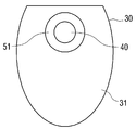
도 5는 타겟 베이스가 애노드 타겟보다 더 큰 면적을 가지는 예를 나타내는 도면,
도 6은 도 2에 도시된 튜브 하우징에 공랭식 냉각수단이 설치된 예를 나타내는 단면도,
도 7은 및 도 8은 도 2에 도시된 튜브 하우징에 수냉/유냉식 냉각수단이 설치된 다양한 예를 나타내는 단면도이다.1 is a schematic view showing that the focal spot point is changed and the position of the X-ray transmission phase is changed as the high-pressure conductor of the conventional X-ray tube apparatus is expanded;
Figure 2 is a schematic cross-sectional view showing an X-ray tube device according to an embodiment of the present invention,
3 is an enlarged view showing part III shown in FIG. 2;
4 is a view seen from the IV direction shown in FIG.
5 shows an example in which the target base has a larger area than the anode target;
6 is a cross-sectional view showing an example in which an air-cooled cooling means is installed in the tube housing shown in FIG.
7 and 8 are cross-sectional views illustrating various examples in which water / cooling cooling means are installed in the tube housing illustrated in FIG. 2.
이하, 첨부된 도면을 참고하여 본 발명의 일 실시예에 따른 X선 튜브장치의 구성을 설명한다.Hereinafter, with reference to the accompanying drawings will be described the configuration of the X-ray tube device according to an embodiment of the present invention.
도 2를 참고하면, 본 발명의 일 실시예에 따른 X선 튜브장치는 튜브 하우징(10), 전극(20), 고압 컨덕터(30), 애노드(anode) 타겟(40) 및 타겟 베이스(50)를 포함한다.2, the X-ray tube device according to an embodiment of the present invention is the
튜브 하우징(10)은 내측에 절연유(14)가 장입되며, 이 절연유(14)를 통해 고압 컨덕터(30)에서 발생하는 고압전류가 X선 튜브장치(1) 외측으로 전가되는 것을 방지한다. 또한 절연유(14)는 고압 컨덕터(30)의 일부와 접촉하면서 고압 컨덕터(30)를 냉각하는 역할도 한다.The
또한 튜브 하우징(10)은 일부가 튜브 하우징(10)으로 인입되는 고압 컨덕터(30)를 지지하기 위한 절연커버(11)가 튜브 하우징(10) 내측에 설치된다. 절연커버(11)는 제1 연결링(12)을 통해 고압 컨덕터(30)와 전기적으로 절연되며, 고압 컨덕터(30)에 흐르는 고압전류와 그라운드에 해당하는 튜브 하우징(10)을 상호 절연한다. 이와 같은 절연커버(11)는 절연효과를 극대화하기 위해 글라스 또는 세라믹으로 형성하는 것이 바람직하다.In addition, the
제1 연결링(12)은 절연커버(11)와 접합이 가능한 정도의 열팽창 계수를 가지며, 절연커버(11)와 고압 컨덕터(30) 사이에서 발생하는 열팽창에 의한 충격을 완화시킬 수 있는 코바(Kovar) 합금으로 이루어진다. 이 경우 고압 컨덕터(30)는 고 열전도율을 가지는 재질 예를 들면, 구리, 은, 흑연 또는 다이아몬드로 이루어진다.The
더욱이, 튜브 하우징(10)은 상측 일부에 고압 컨덕터(30)가 관통할 수 있도록 개구(13)가 형성되고, 이 개구(13)에는 고압 컨덕터(30) 상측을 감싸는 외부커버(15)가 결합된다.In addition, the
외부커버(15)는 하단에 제2 연결링(17)을 통해 절연커버(11)와 결합된다. 이 경우 외부커버(15)는 수직으로 배치된 고압 컨덕터(30)의 상부를 둘러싸며, 외부커버(15)의 상단부에는 애노드 타겟(40)에서 방사되는 X선이 투과하는 윈도우(15a)가 배치된다. 윈도우(15a)는 X선의 투과율을 높이기 위해 베릴륨(beryllium)으로 형성되는 것이 바람직하다.The
한편, 상호 결합된 절연커버(11)와 외부커버(15)는 내측에 진공부(18)를 형성하며, 이러한 진공부(18)는 1×10E-6torr 이하의 고 진공상태를 유지함으로써 절연파괴강도가 높은 절연체의 역할을 한다. 또한 진공부(18)는 고압 컨덕터(30)로부터 절연커버(11)나 외부커버(15)로 열복사가 이루어진다.On the other hand, the
전극(20)은 고압 컨덕터(30)에 대하여 대략 직각으로 배치되도록 외부커버(15)의 일측에 수평으로 설치된다. 이러한 전극(20)은 관전류를 발생하고 이 관전류를 애노드 타겟(40)에 집속시킨다.The
상기 전극(20)은 다음과 같은 구성 즉, 외부로부터 전원을 인가받아 히팅됨으로써 전자를 발생시키는 캐소드 필라멘트(cathode filament)(21)와, 캐소드 필라멘트(21)에서 발생한 전자의 양을 조절하는 그리드(grid) 전극(23)과, 캐소드 필라멘트(21)에서 발생한 전자를 애노드 타겟(40)으로 집속시키는 포커스(focus) 전극(25)과, 전극 커버(27)를 각각 포함한다. 이 경우, 전극 커버(27)는 내측에 캐소드 필라멘트(21), 그리드 전극(23) 및 포커스 전극(25)을 포함하며, 내측은 진공상태를 유지한다.The
고압 컨덕터(30)는 대략 봉형상으로 이루어지며, 상단에 애노드 타겟(40) 및 타겟 베이스(50)가 적층 배치되는 경사면(31)이 형성된다. 이러한 고압 컨덕터(30)는 직접 접촉하는 타겟 베이스(50)로부터 열의 흡수가 가능하도록 비교적 열전도율이 높은 구리(Cu)로 제작될 수 있다. 이 경우 고압 컨덕터(30)의 재질은 구리에 한정되지 않고 열팽창계수가 낮은 재질 예를 들면, 세라믹, 쿼츠(quartz), 글래스 및 다이아몬드 중 어느 하나로 이루어지는 것도 물론 가능하다.The
이 경우 세라믹, 쿼츠 및 글래스의 표면은 통전 가능한 물질 예를 들면, 텅스텐, 구리 및 은 등으로 코팅을 하는 것이 바람직하다.In this case, the surfaces of the ceramics, quartz and glass are preferably coated with an electrically conductive material such as tungsten, copper, silver, or the like.
또한 고압 컨덕터(30)는 고압전극(33)과 접속된 하단부가 절연커버(11)의 외부로 노출됨에 따라 튜브 하우징(10)에 장입되어 있는 절연유(14)와 접촉된다. 이에 따라 고압 컨덕터(30)는 고압 컨덕터(30) 보다 낮은 온도를 유지하는 절연유(14)와의 접촉을 통해 냉각된다.In addition, the
한편, 고압 컨덕터(30)는 상기한 바와 같이 고 열팽창성을 갖는 구리로 이루어지는 것으로 설명하였으나, 이에 제한되지 않고 타겟(40)의 열팽창계수보다 작거나 같은 열팽창계수를 가지는 재질 예를 들면, 타겟(40)의 재질과 동일한 텅스텐으로 이루어지는 것도 물론 가능하다.On the other hand, the high-
이와 같이 고압 컨덕터(30)가 텅스텐으로 이루어지는 경우, Cu로 형성되는 경우에 비해 고압 컨덕터(30)가 열팽창되는 현상을 크게 줄일 수 있으므로, 애노드 타겟(40)의 포컬 스폿 포인트가 변경되는 것을 방지할 수 있다.As such, when the
더욱이, 고압 컨덕터(30)는 내측으로 길이방향을 따라 절연유(14)가 유입될 수 있도록 장홈(35)을 형성하여, 고압 컨덕터(30)가 절연유(14)와 접촉할 수 있는 면적을 늘려 고압 컨덕터(30)의 냉각효율을 높일 수 있다.Furthermore, the
이 경우, 장홈(35)은 내주면에 CVD(chemical vapor deposition) 또는 스퍼터링(sputtering) 공정을 통해 소정 두께의 열흡수층(37)이 코팅 형성될 수 있다.In this case, the
열흡수층(37)은 일부(37a)가 타겟 베이스(50)의 저면과 접촉하며, 이에 따라 열흡수층(37)의 일부(37a)를 통해 타겟 베이스(50)의 고열을 흡수하여 전체 열흡수층(37)으로 분산시킴에 따라 애노드 타겟(40)에 가해지는 열충격을 크게 줄일 수 있다.The
이와 같은 열흡수층(37)은 열전도율이 높은 다이아몬드, 구리, 은 및 흑연 중 어느 하나로 이루어질 수 있다.The
애노드 타겟(40)은 얇은 두께 예를 들면, 미소 초점용으로 적합한 10㎛ 이하의 두께를 가지는 디스크 형상으로 이루어지며, 고압 컨덕터(30)의 경사면(31)에 배치된 타겟 베이스(50) 상에 고정된다. 이와 같은 애노드 타겟(40)은 X선의 효율이 타겟의 원자번호가 높을수록 효율이 높아지는 것을 고려하여 원자번호 및 녹는점이 높은 텅스텐(W)(원자번호: 75, 녹는점: 3450℃)으로 형성한다. 이 경우 텅스텐 이외에 몰리브덴, 구리, 금, Re.W(리늄텅스텐) 중 어느 하나를 사용하는 것도 가능하다.The
타겟 베이스(50)는, 도 3 및 도 4와 같이, 고압 컨덕터(30)의 경사면(31)에 접촉된 상태로 고정 설치되며 대략 디스크 형상으로 이루어진다. 이러한 타겟 베이스(50)는 관전류가 애노드 타겟(40)에 집속되면서 X선이 발생할 때 발생하는 많은 열을 신속하게 흡수할 수 있도록 열전도율이 높고 녹는점이 애노드 타겟(40) 보다 높은 재질 예를 들면, 다이아몬드로 이루어지는 것이 바람직하다.3 and 4, the
이 경우, 타겟 베이스(50)는 고열이 발생되는 지점의 수직방향 즉, 애노드 타겟(40)의 저면에 배치함으로써(도 3 참고) 열집중부위의 표면적을 넓힐 수 있다. 이에 따라 애노드 타겟(40)에 집중되는 열을 신속하게 분산시켜 애노드 타겟(40)의 냉각효율을 높임으로써 열집중으로 인한 애노드 타겟(40)의 수명을 단축을 방지할 수 있다.In this case, the
아울러, 도 5와 같이, 타겟 베이스(51)는 애노드 타겟(40) 보다 더 큰 직경으로 형성할 수 있으며, 이 경우 애노드 타겟(40)과 직경이 같은 경우에 비해 열분포 면적을 늘릴 수 있어 애노드 타겟(40)의 냉각효율을 더욱 향상시킬 수 있다.In addition, as shown in FIG. 5, the
상술한 본 발명의 일 실시예에 따른 X선 튜브장치(1)는 튜브 하우징(10) 내측에 장입된 절연유(14)를 냉각시키기 위한 냉각수단을 구비할 수 있다. 이 경우 냉각수단은 공랭식 냉각수단 및 수냉/유냉식 냉각수단 중 어느 하나를 적용할 수 있다.
먼저, 도 6을 참조하면, 공랭식 냉각수단은 방열부재(71) 및 냉각팬(73)으로 이루어질 수 있다. 방열부재(71)는 튜브 하우징(10)의 측면부에 적어도 1이상 설치되며, 열전도율이 높은 금속 예를 들면 Cu 또는 Al로 이루어진다.First, referring to Figure 6, the air-cooled cooling means may be composed of a
이러한 방열부재(71)는 다수의 방열핀을 구비하는 것이 바람직하다. 하지만 방열부재(71)는 이러한 형상에 제한되지 않고 히트 파이프(미도시)로 제작하는 것도 물론 가능하다.The
냉각팬(73)은 방열부재(71)로 흡수된 열을 강제 배출하여 방열부재(71)를 강제 냉각시키기 위한 것으로 방열부재(71)의 일측면에 접하도록 배치된다.The cooling
또한, 도 7을 참고하면, 수냉식 냉각수단은 냉매 순환장치(80)와 냉매(통상의 냉매 물질 또는 냉수)의 유로(81)를 튜브 하우징(10)의 측면부에 접촉하도록 설치하여 절연유(14)를 냉각할 수 있다. 이 경우 유로(81)는 통상의 파이프 형상으로 이루어진다.In addition, referring to FIG. 7, the water-cooled cooling means installs a
한편 도면에 도시하지는 않았으나 튜브 하우징(10)의 측면부 뿐만 아니라 튜브 하우징(10)이 원통으로 이루어질 경우, 유로(81)를 튜브 하우징(10)의 외주를 따라 나선 방향으로 연속적으로 접촉되도록 설치하는 것도 가능하다.On the other hand, although not shown in the drawings, when the
이러한 수냉식 냉각수단의 경우, 도 8과 같이, 튜브 하우징(10)의 측면부와 파이프(81) 사이에 방열부재(71)를 상호 접촉하도록 설치하는 것도 물론 가능하다.In the case of the water-cooled cooling means, as shown in FIG. 8, it is of course possible to install the
이와 같이 구성된 본 발명의 일 실시예에 따른 X선 튜브장치는 애노드 타겟(40)의 작은 사이즈의 포컬 스폿 포인트에 집속되는 관전류에 의해 발생하는 다량의 고열을 열전도율과 녹는점이 매우 높은 타겟 베이스(50)를 통해 흡수함으로써 애노드 타겟(40)을 냉각할 수 있다. 이에 따라 애노드 타겟(40)은 X선 튜브장치(1)를 장기간 사용함에 따라 애노드 타겟(40)의 포컬 스폿 포인트에 대응하는 부분이 열집중으로 인해 파손되는 것을 방지하는 것은 물론, 애노드 타겟(40)의 수명을 연장시킬 수 있다.X-ray tube device according to an embodiment of the present invention configured as described above is a
또한, 애노드 타겟(40)에서 발생된 열은 타겟 베이스(50)를 통해 장홈(35) 내주면의 열흡수층(37)으로 신속하게 분산된 후, 열흡수층(37)에 접촉된 절연유(14)로 순차 흡수됨에 따라 고압 컨덕터(30)를 효과적으로 냉각시킬 수 있다. 이와 같은 냉각구조를 통해 고압 컨덕터(30)는 종래에 비해 열팽창이 현저히 줄어들어 애노드 타겟(40)의 위치가 변경되는 것을 최대한 억제시킬 수 있다. 따라서 애노드 타겟(40)에 설정되는 포컬 스폿 포인트의 변경을 최대한 억제할 수 있다.In addition, the heat generated from the
이상과 같이, 본 발명은 비록 한정된 실시예와 도면에 의해 설명되었으나, 본 발명은 이것에 의해 한정되지 않으며, 본 발명이 속하는 기술 분야에서 통상의 지식을 가진 자에 의해 본 발명의 기술 사상과 아래에 기재될 특허청구범위의 균등범위 내에서 다양한 수정 및 변형 가능함은 물론이다.While the present invention has been particularly shown and described with reference to exemplary embodiments thereof, it is to be understood that the invention is not limited to the disclosed exemplary embodiments. It will be understood by those skilled in the art that various changes in form and details may be made therein without departing from the spirit and scope of the invention.
10: 튜브 하우징 11: 절연커버
14: 절연유 15: 외부커버
18: 진공부 20: 전극
30: 고압 컨덕터 35: 장홈
37: 열흡수층 40: 애노드 타겟
50: 타겟 베이스 71: 방열부재
73: 냉각팬 80: 냉매 순환장치
81: 냉매 유로10: tube housing 11: insulation cover
14: insulating oil 15: outer cover
18: vacuum portion 20: electrode
30: high voltage conductor 35: long groove
37: heat absorbing layer 40: anode target
50: target base 71: heat dissipation member
73: cooling fan 80: refrigerant circulation device
81: refrigerant path
Claims (14)
상기 튜브 하우징에 일부가 삽입되며, 일부가 진공부에 속하고 나머지 부분이 상기 절연유와 접촉되는 고압 컨덕터(H/V conductor);
상기 진공부에 속하는 상기 고압 컨덕터의 경사면에 고정된 타겟 베이스; 및
상기 타겟 베이스의 상면에 밀착 고정된 애노드 타겟;를 포함하며,
상기 타겟 베이스는 상기 애노드 타겟보다 녹는점이 높고 상기 고압 컨덕터보다 열전도율이 높은 재질로 이루어지며,
상기 고압 컨덕터는 내측을 따라 상기 절연유가 유입되는 장홈을 형성하고, 상기 장홈의 내주면에 상기 타겟 베이스의 저면과 접하는 열흡수층이 코팅되고,
상기 타겟은 텅스텐, 몰리브덴, 구리, 금, Re.W(리늄텅스텐) 중 어느 하나로 이루어지고, 상기 타겟 베이스는 다이아몬드로 이루어지며,
상기 고압 컨덕터는 상기 타겟의 열팽창계수보다 작거나 같은 열팽창계수를 가지는 재질로 이루어지는 것을 특징으로 하는 X선 튜브장치.A tube housing filled with insulating oil therein;
A high voltage conductor having a portion inserted into the tube housing, a portion belonging to a vacuum portion, and the remaining portion contacting the insulating oil;
A target base fixed to an inclined surface of the high voltage conductor belonging to the vacuum unit; And
And an anode target fixed to the upper surface of the target base.
The target base is made of a material having a higher melting point than the anode target and a higher thermal conductivity than the high voltage conductor,
The high voltage conductor forms a long groove into which the insulating oil flows along an inner side thereof, and a heat absorption layer is coated on an inner circumferential surface of the long groove to contact a bottom surface of the target base.
The target is made of any one of tungsten, molybdenum, copper, gold, Re.W (linium tungsten), the target base is made of diamond,
The high-pressure conductor is an X-ray tube device, characterized in that made of a material having a thermal expansion coefficient less than or equal to the thermal expansion coefficient of the target.
상기 연결링은 상기 절연커버와 접합이 가능한 열팽창 계수를 가지는 것을 특징으로 하는 X선 튜브장치.According to claim 1, The insulating cover for supporting the high voltage conductor is connected to the high voltage conductor by a connecting ring,
The connection ring is an X-ray tube device, characterized in that it has a thermal expansion coefficient that can be bonded to the insulating cover.
상기 연결링의 재질은 코바(kovar) 합금인 것을 특징으로 하는 X선 튜브장치.The material of claim 13, wherein the insulation cover is made of ceramic or glass.
X-ray tube device, characterized in that the material of the connection ring is a kovar (kovar) alloy.
Priority Applications (1)
| Application Number | Priority Date | Filing Date | Title |
|---|---|---|---|
| KR1020100121909A KR101150778B1 (en) | 2010-12-02 | 2010-12-02 | X-ray tube device of industrial CT equipment |
Applications Claiming Priority (1)
| Application Number | Priority Date | Filing Date | Title |
|---|---|---|---|
| KR1020100121909A KR101150778B1 (en) | 2010-12-02 | 2010-12-02 | X-ray tube device of industrial CT equipment |
Publications (1)
| Publication Number | Publication Date |
|---|---|
| KR101150778B1 true KR101150778B1 (en) | 2012-06-14 |
Family
ID=46607168
Family Applications (1)
| Application Number | Title | Priority Date | Filing Date |
|---|---|---|---|
| KR1020100121909A Active KR101150778B1 (en) | 2010-12-02 | 2010-12-02 | X-ray tube device of industrial CT equipment |
Country Status (1)
| Country | Link |
|---|---|
| KR (1) | KR101150778B1 (en) |
Cited By (7)
| Publication number | Priority date | Publication date | Assignee | Title |
|---|---|---|---|---|
| KR20160013457A (en) * | 2014-07-25 | 2016-02-04 | 이화여자대학교 산학협력단 | An inner-mounted x-ray collimator having air-cooling structure |
| KR101948909B1 (en) | 2017-07-31 | 2019-02-15 | 주식회사 엑스엘 | Portable X-ray Tube |
| CN111787676A (en) * | 2020-07-27 | 2020-10-16 | 辽宁道特凯力科技有限公司 | Frequency conversion KV control system of medical diagnosis X-ray high-voltage generator |
| KR20220095159A (en) * | 2020-12-29 | 2022-07-06 | 태진우 | X-ray generating apparatus with vacuum heat radiation structure |
| CN115172123A (en) * | 2022-05-19 | 2022-10-11 | 瑞茂光学(深圳)有限公司 | X-ray vacuum light pipe structure |
| CN115623650A (en) * | 2022-11-03 | 2023-01-17 | 中国科学院国家空间科学中心 | X-ray modulator system |
| CN117479406A (en) * | 2022-07-28 | 2024-01-30 | 西门子医疗有限公司 | Multi-tube X-ray radiator housing, multi-tube X-ray source and X-ray device |
Citations (4)
| Publication number | Priority date | Publication date | Assignee | Title |
|---|---|---|---|---|
| JPS61107642A (en) | 1984-10-30 | 1986-05-26 | Mitsubishi Electric Corp | Cooling method of target for generating x-rays |
| JPH05334977A (en) * | 1992-05-29 | 1993-12-17 | Shimadzu Corp | X-ray tube |
| US5768338A (en) | 1994-10-28 | 1998-06-16 | Shimadzu Corporation | Anode for an X-ray tube, a method of manufacturing the anode, and a stationary anode X-ray tube |
| JP2009099565A (en) * | 2007-10-11 | 2009-05-07 | Kratos Analytical Ltd | Electrode for x-ray device |
-
2010
- 2010-12-02 KR KR1020100121909A patent/KR101150778B1/en active Active
Patent Citations (4)
| Publication number | Priority date | Publication date | Assignee | Title |
|---|---|---|---|---|
| JPS61107642A (en) | 1984-10-30 | 1986-05-26 | Mitsubishi Electric Corp | Cooling method of target for generating x-rays |
| JPH05334977A (en) * | 1992-05-29 | 1993-12-17 | Shimadzu Corp | X-ray tube |
| US5768338A (en) | 1994-10-28 | 1998-06-16 | Shimadzu Corporation | Anode for an X-ray tube, a method of manufacturing the anode, and a stationary anode X-ray tube |
| JP2009099565A (en) * | 2007-10-11 | 2009-05-07 | Kratos Analytical Ltd | Electrode for x-ray device |
Cited By (11)
| Publication number | Priority date | Publication date | Assignee | Title |
|---|---|---|---|---|
| KR20160013457A (en) * | 2014-07-25 | 2016-02-04 | 이화여자대학교 산학협력단 | An inner-mounted x-ray collimator having air-cooling structure |
| KR101598288B1 (en) * | 2014-07-25 | 2016-02-29 | 이화여자대학교 산학협력단 | An inner-mounted x-ray collimator having air-cooling structure |
| KR101948909B1 (en) | 2017-07-31 | 2019-02-15 | 주식회사 엑스엘 | Portable X-ray Tube |
| CN111787676A (en) * | 2020-07-27 | 2020-10-16 | 辽宁道特凯力科技有限公司 | Frequency conversion KV control system of medical diagnosis X-ray high-voltage generator |
| KR20220095159A (en) * | 2020-12-29 | 2022-07-06 | 태진우 | X-ray generating apparatus with vacuum heat radiation structure |
| KR102755628B1 (en) * | 2020-12-29 | 2025-01-21 | 태진우 | X-ray generating apparatus with vacuum heat radiation structure |
| CN115172123A (en) * | 2022-05-19 | 2022-10-11 | 瑞茂光学(深圳)有限公司 | X-ray vacuum light pipe structure |
| CN117479406A (en) * | 2022-07-28 | 2024-01-30 | 西门子医疗有限公司 | Multi-tube X-ray radiator housing, multi-tube X-ray source and X-ray device |
| US12225655B2 (en) | 2022-07-28 | 2025-02-11 | Siemens Healthineers Ag | X-ray emitter housing with at least one electrically conductive housing portion |
| CN117479406B (en) * | 2022-07-28 | 2025-02-14 | 西门子医疗股份公司 | Multi-tube X-ray radiator housing, multi-tube X-ray source and X-ray device |
| CN115623650A (en) * | 2022-11-03 | 2023-01-17 | 中国科学院国家空间科学中心 | X-ray modulator system |
Similar Documents
| Publication | Publication Date | Title |
|---|---|---|
| KR101150778B1 (en) | X-ray tube device of industrial CT equipment | |
| JP6039282B2 (en) | Radiation generator and radiation imaging apparatus | |
| KR101563521B1 (en) | Radiation generating apparatus and radiation imaging apparatus | |
| US6215852B1 (en) | Thermal energy storage and transfer assembly | |
| JP5796990B2 (en) | X-ray generator and X-ray imaging apparatus using the same | |
| JP4749456B2 (en) | X-ray tube cooling system and X-ray tube generator | |
| JP4142748B2 (en) | High performance X-ray generator with cooling system | |
| US6477231B2 (en) | Thermal energy transfer device and x-ray tubes and x-ray systems incorporating same | |
| CN100479755C (en) | Stationary computerized tomography system with small-sized X-ray source assembly | |
| JP5200103B2 (en) | Thermionic electron emitter and x-ray source including the same | |
| KR101140993B1 (en) | Structure of rotating anode type x-ray tube having improved thermal emitting efficiency | |
| US8761345B2 (en) | X-ray tube | |
| US6594341B1 (en) | Liquid-free x-ray insert window | |
| JPH11510955A (en) | X-ray generator having heat transfer device | |
| US6519318B1 (en) | Large surface area x-ray tube shield structure | |
| KR20130098416A (en) | Radiation generating apparatus and radiation imaging apparatus | |
| JP2002334675A (en) | X-ray tube having temperature gradient device and x-ray system | |
| US8000450B2 (en) | Aperture shield incorporating refractory materials | |
| US20130156161A1 (en) | X-ray tube aperture having expansion joints | |
| US20130148781A1 (en) | Radiation generating apparatus | |
| US6252937B1 (en) | High thermal performance cathode via heat pipes | |
| US6362415B1 (en) | HV connector with heat transfer device for X-ray tube | |
| JP5267150B2 (en) | X-ray tube device | |
| US7050542B2 (en) | Device for generating x-rays having a heat absorbing member | |
| KR101089233B1 (en) | Radiating member of wire tube |
Legal Events
| Date | Code | Title | Description |
|---|---|---|---|
| A201 | Request for examination | ||
| PA0109 | Patent application |
Patent event code: PA01091R01D Comment text: Patent Application Patent event date: 20101202 |
|
| PA0201 | Request for examination | ||
| E902 | Notification of reason for refusal | ||
| PE0902 | Notice of grounds for rejection |
Comment text: Notification of reason for refusal Patent event date: 20110916 Patent event code: PE09021S01D |
|
| E701 | Decision to grant or registration of patent right | ||
| PE0701 | Decision of registration |
Patent event code: PE07011S01D Comment text: Decision to Grant Registration Patent event date: 20120430 |
|
| GRNT | Written decision to grant | ||
| PR0701 | Registration of establishment |
Comment text: Registration of Establishment Patent event date: 20120522 Patent event code: PR07011E01D |
|
| PR1002 | Payment of registration fee |
Payment date: 20120523 End annual number: 3 Start annual number: 1 |
|
| PG1601 | Publication of registration | ||
| FPAY | Annual fee payment |
Payment date: 20150507 Year of fee payment: 4 |
|
| PR1001 | Payment of annual fee |
Payment date: 20150507 Start annual number: 4 End annual number: 4 |
|
| FPAY | Annual fee payment |
Payment date: 20160504 Year of fee payment: 5 |
|
| PR1001 | Payment of annual fee |
Payment date: 20160504 Start annual number: 5 End annual number: 5 |
|
| FPAY | Annual fee payment |
Payment date: 20170510 Year of fee payment: 6 |
|
| PR1001 | Payment of annual fee |
Payment date: 20170510 Start annual number: 6 End annual number: 6 |
|
| FPAY | Annual fee payment |
Payment date: 20180510 Year of fee payment: 7 |
|
| PR1001 | Payment of annual fee |
Payment date: 20180510 Start annual number: 7 End annual number: 7 |
|
| FPAY | Annual fee payment |
Payment date: 20190508 Year of fee payment: 8 |
|
| PR1001 | Payment of annual fee |
Payment date: 20190508 Start annual number: 8 End annual number: 8 |
|
| FPAY | Annual fee payment |
Payment date: 20200507 Year of fee payment: 9 |
|
| PR1001 | Payment of annual fee |
Payment date: 20200507 Start annual number: 9 End annual number: 9 |
|
| FPAY | Annual fee payment |
Payment date: 20210510 Year of fee payment: 10 |
|
| PR1001 | Payment of annual fee |
Payment date: 20210510 Start annual number: 10 End annual number: 10 |
|
| FPAY | Annual fee payment |
Payment date: 20220509 Year of fee payment: 11 |
|
| PR1001 | Payment of annual fee |
Payment date: 20220509 Start annual number: 11 End annual number: 11 |