KR101144156B1 - Auto unfurl tent that is easy to install and easy to fixed on the ground - Google Patents
Auto unfurl tent that is easy to install and easy to fixed on the ground Download PDFInfo
- Publication number
- KR101144156B1 KR101144156B1 KR1020110090476A KR20110090476A KR101144156B1 KR 101144156 B1 KR101144156 B1 KR 101144156B1 KR 1020110090476 A KR1020110090476 A KR 1020110090476A KR 20110090476 A KR20110090476 A KR 20110090476A KR 101144156 B1 KR101144156 B1 KR 101144156B1
- Authority
- KR
- South Korea
- Prior art keywords
- tent
- deployment
- spring
- sleeve
- shuttle
- Prior art date
- Legal status (The legal status is an assumption and is not a legal conclusion. Google has not performed a legal analysis and makes no representation as to the accuracy of the status listed.)
- Expired - Fee Related
Links
Images


Classifications
-
- E—FIXED CONSTRUCTIONS
- E04—BUILDING
- E04H—BUILDINGS OR LIKE STRUCTURES FOR PARTICULAR PURPOSES; SWIMMING OR SPLASH BATHS OR POOLS; MASTS; FENCING; TENTS OR CANOPIES, IN GENERAL
- E04H15/00—Tents or canopies, in general
- E04H15/28—Umbrella type tents
-
- E—FIXED CONSTRUCTIONS
- E04—BUILDING
- E04H—BUILDINGS OR LIKE STRUCTURES FOR PARTICULAR PURPOSES; SWIMMING OR SPLASH BATHS OR POOLS; MASTS; FENCING; TENTS OR CANOPIES, IN GENERAL
- E04H15/00—Tents or canopies, in general
- E04H15/32—Parts, components, construction details, accessories, interior equipment, specially adapted for tents, e.g. guy-line equipment, skirts, thresholds
- E04H15/34—Supporting means, e.g. frames
- E04H15/44—Supporting means, e.g. frames collapsible, e.g. breakdown type
- E04H15/48—Supporting means, e.g. frames collapsible, e.g. breakdown type foldable, i.e. having pivoted or hinged means
Landscapes
- Engineering & Computer Science (AREA)
- Architecture (AREA)
- Civil Engineering (AREA)
- Structural Engineering (AREA)
- Tents Or Canopies (AREA)
Abstract
설치가 빠르고 확실하며 또한 설치 후에도 고정 및 자세유지가 쉬운 돔형 이중프레임 구조의 자동 펼침 방식 텐트가 개시된다. 본 발명은 텐트를 접어서 보관할 때, 강화된 전개스프링이 장기간 강한 인장상태에 노출되고 결국 영구변형이 발생하며 텐트의 전개기능 상실로 이어지는 단점을 해결하고 탄성로프와 지면고정 못에 의한 고정이 어려운 자동 전개식텐트의 지면고정 문제를 해결하기 위한 것이다.
상부 폴(60)을 따라 내부프레임(20)을 상승시키는 역할을 하는 전개스프링(42)을 내부프레임에 설치된 슬리브(21)를 관통하여 외부프레임(10)에 연결하였으며 내부프레임의 상승(외부프레임 전개)이 완료된 이후 외부프레임에서 전개스프링이 의도적으로 탈락되어 내부프레임을 따라 후퇴하도록 하는 스프링결합 해제구조가 본 발명에 소개된다. 이는 스프링이 팽팽히 당겨져 있는 상황에서 셔틀(shuttle:11)을 물고 있는 클로(claw:22) 옆쪽으로 셔틀을 잡아당겨 빼내는 방식으로 결합고리를 풀어내는 방식으로 이루어지며, 결합이 해제된 전개스프링(42)은 뒤로 후퇴하고 더 이상 강한 인장상태를 지속하지 않아도 된다.
또한 본 발명에서는, 내부프레임의 일단이 결합된 상단슬리브(30)와 전개스프링의 일단이 결합된 중단슬리브(40)를 서로 결합시켜 텐트의 전개를 완료한 다음, 결합부분을 분리하여 전개스프링 일단을 하부 폴(70) 쪽으로 이동하여 결합시키는 구성이 소개된다. 이에 따라 전개완료 후 내부프레임 하단과 하부 폴을 서로 연결하는 전개스프링은 하부 폴의 연장에도 불구하고 지나치게 늘어나지 않으면서 상부 폴과 하부 폴을 탄성결합 상태로 서로 잡아당길 수 있다.
본 발명은, 통상의 자동 전개식텐트에서 별다른 추가 구조재나 추가 스프링을 장비하지 않고도 전개스프링의 탄성을 보존할 수 있으며, 텐트 상부 구조체를 전개스프링의 탄성에 의해서만 하부 폴(lower pole)에 연결시키고 있으므로 하부 폴에 진동이 발생하지 않게 되고 결과적으로 텐트 전체의 지면 고정상태를 장시간 동안 안정적으로 유지시킬 수 있다.An automatic unfolding tent with a domed, double-frame structure is disclosed that is quick and secure to install and easy to fix and maintain after installation. In the present invention, when the tent is folded and stored, the reinforced deployment spring is exposed to a strong tension state for a long time, and eventually the permanent deformation occurs, which leads to a loss of the deployment function of the tent, and is difficult to fix by the elastic rope and the ground fixing nail. This is to solve the ground fixing problem of the deployable tent.
The expansion spring 42, which serves to raise the inner frame 20 along the upper pole 60, is connected to the outer frame 10 through the sleeve 21 installed in the inner frame, and the inner frame is raised (outer frame). After the deployment) is completed, a spring coupling release structure is introduced in the present invention to allow the deployment spring to be intentionally dropped in the outer frame and retract along the inner frame. This is done by unscrewing the engagement ring by pulling the shuttle to the side of the claw (22) holding the shuttle (11) while the spring is pulled tightly. ) Retreat back and no longer need to be in strong tension.
In addition, in the present invention, the upper sleeve 30 is coupled to one end of the inner frame and the suspension sleeve 40 is coupled to one end of the deployment spring to each other to complete the deployment of the tent, then separate the coupling portion one end of the deployment spring Is introduced to move the coupling toward the lower pole (70). Accordingly, the deployment spring for connecting the lower and lower poles of the inner frame after the completion of the deployment can pull the upper pole and the lower pole in an elastically coupled state without stretching excessively despite the extension of the lower pole.
In the present invention, the elasticity of the deployment spring can be preserved without any additional structural member or additional spring in the normal automatic deployment tent, and the tent upper structure is connected to the lower pole only by the elasticity of the deployment spring. Vibration does not occur in the lower pole, and as a result, the ground of the entire tent can be kept stable for a long time.
Description
본 발명은 설치가 빠르고 확실하며 또한 설치 후에도 고정 및 자세유지가 쉬운 돔형 이중프레임 구조의 자동 펼침 방식 텐트에 관한 것이다.The present invention relates to an automatic unfolding tent of dome type double frame structure that is fast and securely installed and easy to fix and maintain after installation.
우산처럼 접혀져 있다가 간단한 조작에 의해 돔 형태로 한번에 펼쳐질 수 있는 자동 전개식 텐트는, 비록 동급의 조립식 텐트에 비해 더 무겁고 접었을 때의 부피도 더 크다는 단점이 있지만 설치와 해체가 매우 쉬워 다수의 텐트를 긴급히 설치할 필요가 있을 때, 또는 악천후 때나 산간오지에서 매우 뛰어난 성능을 발휘한다.The self-developing tent, which can be folded like an umbrella and can be unfolded at once by simple operation, has the disadvantages of being heavier and larger when folded than its prefabricated tent, but it is very easy to install and dismantle. Excellent performance when needed urgently, or in bad weather or in remote mountains.
일반적으로 자동 전개식 텐트는 우산보다 훨씬 크고 무거워서 사람의 힘으로 간단히 펼치기 어려우므로 주로 스프링이나 유압기구의 도움을 받아 스스로 펼쳐질 수 있는 구조로 이루어진다. 아래 소개한 선행기술문헌들은 스프링의 탄성 등에 의한 전형적인 우산식 펼침 형태를 갖는 자동 텐트들이다.In general, the self-developing tent is much larger and heavier than an umbrella, so it is difficult to simply unfold by human force, so it is mainly composed of a structure that can be unfolded by itself with the help of a spring or hydraulic mechanism. The prior art documents introduced below are automatic tents having a typical umbrella-type unfolding type by spring elasticity or the like.
(문헌1)은 별도의 탄성기구는 없지만 한번에 펼쳐지는 텐트에서 자주 볼 수 있는 전형적인 방사상의 이중프레임 구조를 잘 보여주고 있다. 여기에서 외부프레임은 텐트외피를 지지하는 메인프레임이고, 내부프레임은 외부프레임을 벌어지게 하고 벌어진 외부프레임을 그 상태로 지지하게 하는 서브프레임이다. 이러한 이중의 프레임 구조는 대부분의 자동전개식 텐트 설계의 기본이 되며, 본 발명에서도 예외는 아니다.Document 1 shows a typical radial double-frame structure that is often found in tents that are unfolded but without a separate elastic mechanism. Here, the outer frame is a main frame that supports the tent envelope, and the inner frame is a subframe that opens the outer frame and supports the opened outer frame in that state. This dual frame structure is the basis of most automatic tent designs and is not an exception in the present invention.
(문헌2)는 전술한 이중 프레임 구조를 약간 개선한 경우인데, 프레임 가운데의 짧은 기둥을 따라 내부프레임이 위로 이동 가능하게 설계한 것이다. 이렇게 되면 텐트를 접었을 때 내부프레임이 외부프레임의 접혀지는 공간 안쪽으로 들어갈 수 있고 따라서 가운데에 내부프레임의 슬라이딩운동을 안내하기 위한 길다란 폴(Pole)을 설치하지 않아도 되므로 텐트 내부의 공간활용성이 높아지는 측면이 있다. 물론 텐트 가운데의 폴을 삭제한 구조이기 때문에 펼쳐져 있을 때의 텐트의 강성, 즉 악천후 저항능력은 상대적으로 부족하다.(Document 2) is a case in which the above-described dual frame structure is slightly improved, and the inner frame is designed to be moved upward along a short column in the center of the frame. In this case, when the tent is folded, the inner frame can go into the folding space of the outer frame, and thus there is no need to install a long pole to guide the sliding movement of the inner frame in the center, thereby increasing the space utilization inside the tent. There is a side. Of course, because the poles in the middle of the tent is removed, the rigidity of the tent when it is unfolded, that is, the ability to resist bad weather, is relatively insufficient.
(문헌3)은 길이방향으로 확장 가능한 이중관 구조의 폴(Pole)에 외부프레임과 내부프레임을 연결하고, 중앙 폴(center pole) 내측에 배치된 스프링의 탄성으로 내부프레임을 펼칠 수 있도록 한 것이다. 이렇게 사람의 힘이 거의 가해지지 않고 내부 스프링의 강한 탄성력으로 저절로 펼쳐질 수 있는 구조가 텐트의 가장 전형적인 자동 전개 구조로 볼 수 있다. 다만 이 경우에도 여전히 중앙 폴은 길이가 짧아 텐트의 지지는 상기 문헌2와 같이 순수하게 외부프레임 들에 의해서만 이루어져야 한다.(3) connects the outer frame and the inner frame to a pole of a double tube structure that extends in the longitudinal direction, and the inner frame can be unfolded by the elasticity of the spring disposed inside the center pole. The most typical automatic deployment structure for tents is such that little force is applied and the structure can be unfolded by the strong spring force of the inner spring. However, even in this case, the center pole is still short, so the tent should be supported only by the outer frames as shown in Document 2 above.
(문헌4)는 상기 문헌2와 문헌3을 조합한 형태이다. 역시 이 경우에도 중앙의 폴에 장착된 스프링의 탄성인장력이 텐트의 펼침 및 지지작용에 근간이 되며, 내부프레임은 통상적인 우산접이 형식이 아닌 외부프레임에 가까운 쪽으로 접혀진다.Document 4 is a combination of Document 2 and Document 3. In this case too, the elastic tension of the spring mounted on the central pole is the basis for the expansion and support of the tent, and the inner frame is folded closer to the outer frame than the usual umbrella folding type.
최근 다양한 강화복합재료와 복합소재 천의 등장으로 텐트를 이루는 부품들의 무게와 부피는 매우 줄어들었다. 따라서 보통의 분해조립식(수동 설치식) 텐트는 조립 전 상태에서 매우 작은 크기와 가벼운 중량을 가지면서도 상대적으로 훌륭하고 넉넉한 거주공간을 제공해 준다.With the advent of various reinforced composite materials and composite fabrics in recent years, the weight and volume of parts forming tents have been greatly reduced. Thus, ordinary dismantled (manual) tents provide a relatively good and spacious living space with very small size and light weight in their pre-assembly condition.
반면 통상적인 수동설치 방식 텐트가 자동식 텐트에 비해 떨어지는 점은 단지 설치와 해체가 번거롭고 어렵다는 점이다. 물론 자동 전개식 텐트는 바로 이 점을 해결하는 과정에서 여러 가지 구조적, 기능적 손해를 보게 된다.On the other hand, the disadvantage of the conventional manual installation tent compared to the automatic tent is that the installation and dismantling are cumbersome and difficult. Of course, self-developed tents suffer from a number of structural and functional damages in the process of addressing this.
자동 전개식 텐트의 구조적 약점으로 우선 내부프레임을 위로 상승시키는 펼침용 스프링의 점진적인 탄성력 저하를 들 수 있다. 예컨대 비슷한 구조인 우산의 경우 손으로 직접 내부프레임을 상승시키므로, 늘 팽팽하게 당겨져 있어야만 하는 자동 펼침용 스프링을 필요로 하지 않는다. 그러나 자동 전개식 텐트는 우산에 비해 매우 크고 무거워서 거의 반드시 펼침힘을 제공해 줄 전개스프링이 필요하게 되는데, 강풍과 비바람에서도 텐트가 쉽게 펼쳐지기 위해서는 상기 전개스프링의 강도(또는 초기 인장/압축 상태)를 비교적 강하게 할 필요가 있다. 따라서 텐트를 접어서 보관할 때, 다시 말해서 강화된 강도의 전개스프링이 장기간 강한 인장상태에서 보관할 때 스프링에는 필연적으로 영구변형이 발생하며 이는 곧 접은 상태가 오래 지속될수록 텐트의 핵심 기능을 떨어뜨려 결국 전개기능 상실로 이어지는 원인이 된다.The structural weakness of the self-developing tent is the gradual drop in elasticity of the spreading spring, which first raises the inner frame upwards. For example, an umbrella having a similar structure raises the inner frame directly by hand, and thus does not require an automatic unfolding spring that must always be pulled tight. However, self-developing tents are much larger and heavier than umbrellas and require a deployment spring that will almost always provide unfolding. In order to easily unfold tents in high winds and rain, the strength of the deployment spring (or initial tension / compression) is relatively high. You need to be strong. Therefore, when the tent is folded and stored, that is, when the expanded strength spring is stored under strong tension for a long time, the spring inevitably causes permanent deformation, which means that the longer the folded state, the lower the tent's core function and eventually the deployment function. It causes the loss.
다음으로 통상의 무폴식(non-pole type) 자동텐트는 물론, 폴(Pole)을 갖고 있는 대부분의 자동 전개식 텐트들 역시 공통적으로 지면에 쉽게 고정하기 어렵다는 약점이 있다. 이는 스스로 기립하는 자동 전개식 텐트에 있어 일종의 숙명과도 같은 것이다. 물론 텐트의 둘레로 고정용 못(지주)을 박고 텐트 꼭대기와 못 사이를 탄성로프로 서로 연결하는 고전적 방법을 쓴다면 가능하겠으나, 이러한 작업을 쓴다면 자동식 텐트의 고유한 장점 즉 설치/해제의 편리함과 악천후시 전개능력을 스스로 잃어버리는 것이나 마찬가지인 셈이 된다. 따라서 이 같은 단점을 없애기 위해서는 일단 전개된 텐트를 통상적인 외부 수작업식 고정방법 보다는 좀 더 쉽고 간편하면서도 확실하게 지면에 고정시킬 수 있어야 한다.Next, most non-pole auto tents, as well as most self-developed tents with poles, have a common disadvantage that they are not easily fixed to the ground. This is a kind of fate for self-developing tents. Of course, it would be possible to use the classical method of anchoring nails around the tent and connecting the top of the tent with the elastic rope to each other with elastic ropes. It is the same as losing one's ability to develop in bad weather. Therefore, in order to eliminate such drawbacks, the deployed tent should be able to be fixed to the ground more easily, conveniently and reliably than the usual external manual fixing method.
가장 유력한 방법은 가운데에 위치한 폴(pole)을 이용하여 지면에 단단히 고정시키는 것이다. 그러나 강체 기둥인 폴은 탄성로프와 달리 지속적인 인장력을 발생시키는 고정부재가 아니다. 따라서 처음에 폴의 하부와 지면을 서로 단단히 고정시켰다 하더라도 바람 등에 의해 텐트 외부프레임이 반복적으로 흔들리면 외부프레임과 일체로 고정된 폴 반복적인 진동에 의해 시간이 점차 지나면서 지면고정부위가 헐거워지게 되고 결국 텐트는 지속적인 강풍에 흔들리다가 뒤집히게 된다. 상술한 자동식 텐트의 단점들은 자동 전개방식 특유의 장점까지도 퇴색시킬 수 있어 상품성을 크게 떨어뜨리는 주요 원인들이기도 하다.The most promising method is to use a pole in the center to hold it firmly to the ground. However, poles, which are rigid columns, are not fastening members that generate a constant tensile force, unlike elastic ropes. Therefore, even if the lower part of the pole and the ground are firmly fixed to each other, if the tent outer frame is repeatedly shaken by wind, etc., the ground level becomes loose as time passes by the repetitive vibration of the pole fixed integrally with the outer frame. The tent is swayed by constant strong winds and overturns. Disadvantages of the above-mentioned automatic tents can also fade even the advantages of the automatic deployment method, which is also a major cause of greatly reducing the merchandise.
본 발명은 위와 같은 단점들을 효과적으로 해결할 수 있도록 창안된 것이며, 휴대 가능한 자동전개식 텐트의 장점을 잃지 않기 위해 통상의 자동전개식 텐트가 보유하는 기본적인 프레임량과 탄성스프링 개수만큼을 보유하되, 어떠한 추가적인 구조재와 추가 스프링도 사용하지 않고서 단지 프레임과 스프링의 교묘한 가변식 연결구조를 통해 상기 단점(스프링 탄성 훼손, 설치 후 고정상태 유지의 어려움)들을 완벽히 해결하는 기술적 수단을 제공한다.The present invention has been devised to effectively solve the above disadvantages, in order not to lose the advantages of the portable self-developed tent, but retains the basic frame amount and the number of elastic springs possessed by the conventional auto-developed tent, any additional structural material and It provides a technical means to completely solve the above shortcomings (damage of spring elasticity, difficulty in maintaining a fixed state after installation) through the artfully variable connecting structure of the frame and the spring without using additional springs.
우선 본 발명은, 일단이 중단슬리브(40)를 통해 상부 폴(60)에 상하이동 가능하도록 장착되고, 상기 상부 폴(60)을 따라 내부프레임(20)을 상승시키는 역할을 하는 전개스프링(42)을 그 타단이 내부프레임에 설치된 내부프레임슬리브(25)를 관통하여 외부프레임(10)에 연결하였으며 내부프레임의 상승(외부프레임 전개)이 완료된 이후 상기 전개스프링의 타단이 외부프레임에서 의도적으로 탈락되어 다시 자신의 일단 결합부 쪽으로 후퇴하도록 하는 스프링결합 해제구조를 도입하였다.First, the present invention, one end is mounted so as to be movable in the
상기 스프링결합 해제구조는 스프링의 탄성력 작용과 수직한 방향으로는 비교적 작은 힘으로 그 결합고리를 해제할 수 있다는 원리를 이용한 것이다. 구체적으로는 스프링이 팽팽히 당겨져 있는 상황에서 셔틀(shuttle:11)을 물고 있는 클로(claw:22) 옆쪽으로 셔틀을 잡아당겨 빼내는 방식으로 결합고리를 풀어내는 것을 의미하며, 결합이 해제된 전개스프링(42)은 뒤로 후퇴하고 더 이상 강한 인장상태를 지속하지 않아도 된다. 이 상태 이후 다시 텐트를 펼치려면 각 전개스프링의 클로에 연결된 클로 당김로프(23)를 하나씩 잡아 당겨 셔틀에 클로를 다시 물리게 해주면 된다. 이 과정은 하나씩 이루어지므로 사용자는 큰 힘을 들이지 않고도 텐트를 펼침 가능 상태로 다시 되돌릴 수 있다.The spring coupling release structure utilizes the principle that the coupling ring can be released with a relatively small force in a direction perpendicular to the spring force action. Specifically, it means to release the coupling ring by pulling the shuttle to the side of the claw (22) holding the shuttle (11) while the spring is pulled tightly, and the release spring ( 42) does not need to retreat back and maintain a strong tension anymore. If you want to expand the tent again after this state, pull the
다음으로 본 발명은, 내부프레임이 장착된 상단슬리브(30)와 전개스프링이 장착된 중단슬리브(40)를 경우에 따라 서로 분리하여 전개스프링 아래쪽이 하부 폴(70) 쪽에 직접 결합될 수 있도록 하였다. 이에 따라 전개스프링은 펼쳐진 텐트의 내부공간을 침범하지 않고, 또한 지나치게 늘어나지도 않으면서 상부 폴과 하부 폴을 탄성결합 상태로 서로 잡아당길 수 있다. 따라서 외부프레임을 고정시키기 위해 하부 폴에 설치된 지면고정판(71)을 지면에 못이나 돌로 고정시켜도 결과적으로 외부프레임은 탄성상태로 지면에 고정된 것이기 때문에 텐트외피가 강풍에 의한 흔들림에 장시간 노출되어도 지면결합부분이 헐거워지지 않는 텐트 구조체가 완성될 수 있다.Next, according to the present invention, the
상기한 탄성결합의 위치와 거리조절 구성은 내부프레임을 따라 전개스프링을 이동시키면서 대각선으로 배치된 스프링을 수직 배치로 변경시켜 유용하게 활용할 수 있다는 기술사상을 담고 있다. 이는 어떠한 추가적인 스프링이나 폴의 구조변경도 필요 없이, 그다지 길지 않은 원래의 전개스프링을 상하부 폴 간 긴 결합에도 다용도로 이용할 수 있고, 그 과정에서 텐트 내부공간의 침범도 발생하지 않는다는 점에서 종래의 전개스프링 결합단 구조와 기술적으로 매우 차별화된다.The position and distance control configuration of the elastic coupling contains a technical idea that it is useful to change the diagonally arranged spring to a vertical arrangement while moving the deployment spring along the inner frame. This means that the original deployment spring, which is not very long, can be used for long coupling between upper and lower poles without any additional spring or pole restructuring, and conventional deployment is not performed in the process because it does not invade the space inside the tent. It is technically very different from the spring-coupled end structure.
본 발명에 따르면, 통상의 자동 전개식텐트에서 별다른 추가 구조재나 추가 스프링을 장비하지 않고도 전개스프링의 탄성을 보존할 수 있는 효과가 있으며, 또한 단지 전개스프링의 탄성에 의해서만 상부구조체를 하부 폴(lower pole)에 연결시키므로 하부 폴에 진동이 발생하지 않게 되고 결과적으로 하부 폴의 지면 고정상태를 장시간 확실하게 유지시킬 수 있는 효과가 있다.According to the present invention, there is an effect of preserving the elasticity of the deployment spring without the addition of additional structural members or additional springs in the conventional automatic deployment tent, and also the upper pole only by the elasticity of the deployment spring lower pole (lower pole) ) So that vibration does not occur in the lower pole, and as a result, there is an effect that can securely maintain the ground of the lower pole for a long time.
이는 통상의 자동 텐트용 전개스프링보다 더 강한 스프링을 본 발명에 적용시킬 수 있다는 것을 의미하며, 곧 텐트의 펼침능력 향상과 지면고정상태 유지능력의 향상으로 이어져 강풍, 비바람 등 악천후에서도 강력한 전개성능과 장시간의 지면부착 유지성능을 발휘할 수 있게 한다. 따라서 자동 전개식 텐트가 갖는 본질적인 상품성, 즉 악천후에서의 설치 및 거주능력을 향상시킬 수 있다.This means that a stronger spring than the general automatic tent deployment spring can be applied to the present invention, which leads to the improvement of the tent's ability to unfold and maintain the ground fixed state, and thus the strong deployment performance even in bad weather such as strong wind and rainy weather. It is possible to exert long-term ground adhesion performance. Therefore, it is possible to improve the intrinsic merchandise of an auto-developed tent, that is, installation and habitability in bad weather.
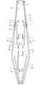
도 1은 본 발명 텐트의 펼치기 전 보관 상태를 도시한 전체 단면도.
도 2는 본 발명 텐트의 펼치기 전 보관 단계에서 주요 결합부분을 확대 도시한 단면도.
도 3은 본 발명 텐트의 전개 직전 준비단계에서 주요 결합부분을 확대 도시한 단면도.
도 4는 본 발명 텐트가 전개 도중의 단계에서 주요 결합부분을 확대 도시한 단면도.
도 5는 본 발명 텐트가 완전히 펼쳐진 전계완료 상태에서 주요 결합부분을 확대 도시한 단면도.
도 6은 본 발명 텐트의 전개 후 지면에 탄성 고정하는 단계에서 주요 결합부분을 확대 도시한 단면도.
도 7 ~ 도 8은 본 발명에서 셔틀(11)에 클로(22)를 물리는 조작 메커니즘을 설명한 3D모델링 사시도.
도 9 ~ 도 10은 본 발명에서 셔틀(11)이 클로(22)에서 빠져 나오는 운동 메커니즘을 설명한 3D모델링 측단면도.
도 11 ~ 도 14는 본 발명에서 도 1 이후의 상태를 순서대로 도시한 전체 단면도.
도 15는 본 발명 텐트에서 외피를 씌운 상태의 3D모델링 사시도.1 is an overall cross-sectional view showing a storage state before expanding the tent of the present invention.
Figure 2 is an enlarged cross-sectional view showing the main coupling portion in the storage step before the expansion of the tent of the present invention.
Figure 3 is an enlarged cross-sectional view showing the main coupling portion in the preparation step just before the deployment of the present invention tent.
Figure 4 is an enlarged cross-sectional view showing the main engaging portion at the stage of the present invention tent deployment.
Figure 5 is an enlarged cross-sectional view showing the main coupling portion in the electric field complete state the tent of the present invention fully deployed.
Figure 6 is an enlarged cross-sectional view showing the main coupling portion in the step of elastically fixing the ground after the deployment of the present invention tent.
7 to 8 is a 3D modeling perspective view illustrating an operation mechanism for snapping the
9 to 10 are 3D modeling side cross-sectional view illustrating the movement mechanism by which the
11 to 14 are all cross-sectional view showing the state after Fig. 1 in order in the present invention.
Figure 15 is a perspective view of the 3D modeling the covering state in the tent of the present invention.
상술한 본 발명의 과제 해결수단을 기술적으로 뒷받침하기 위하여 도면에 포함된 본 발명의 일 실시예를 참조하여 상세히 설명한다.With reference to the embodiment of the present invention included in the drawings in order to technically support the above-described solution of the present invention will be described in detail.
다만 아래의 특정 실시예에서 특정 전문용어를 포함한 구성요소들과 이들의 결합구조가 본 발명에 포괄적으로 내재된 기술적 사상을 제한하는 것은 아니다.However, in the following specific embodiments, the components including the specific terminology and combinations thereof do not limit the technical spirit inherent in the present invention.
도 1에 도시된 본 발명 실시예의 텐트는 외부프레임(10)과 내부프레임(20)이 상부 폴(60) 주위로 상하 회전 가능하도록 방사상으로 다수 배치되고, 또한 상기 상부 폴(60) 주위로 방사상으로 복수 배치된 전개스프링(42)에 의해 상기 내부프레임(20)을 위로 상승시켜 상기 외부프레임(10)을 펼치는 구조를 갖는 전형적인 돔 형 텐트에서 외피를 제거한 프레임 부분을 특정 절단면을 따라 도시한 것이다.The tent of the embodiment of the present invention shown in FIG. 1 is arranged radially in a number such that the
도 1을 포함한 이하의 도면에서는 상부 폴(60), 내외부프레임(20,10), 접이식 연장프레임(16)등이 모두 속이 빈 파이프 형태로 도시된다. 상부폴 내부로 삽입 또는 인출 가능한 하부 폴(70)은 속이 비지 않은 봉 형태이다. 그 외 상부 및 하부 폴을 따라 움직이는 각종 슬리브, 예컨대 외부프레임 속에 내장된 셔틀와이어(14)를 잡아당길 수 있는 와이어슬리브(15)를 비롯하여, 상단/중단/하단 슬리브(30,40,50) 등은 모두 폴(pole) 양쪽으로 나누어져 도시되었지만, 실제로는 폴을 따라 이동할 수 있는 원통형의 슬리브(sleeve)이며, 단지 단면도의 특성상 좌우로 나뉘어져 있는 것처럼 보일 뿐이다. 이 점을 참조하여 이하의 도면을 해석하면 본 발명의 작동구조를 파악하는 데에 더욱 편리하다.In the following drawings including FIG. 1, the
도 1을 참조로 하여 본 발명 텐트가 종래의 자동 전개식 텐트와 차별화되는 주요 기술구성을 알아본다.With reference to Figure 1 looks at the main technical configuration that the present invention tent is differentiated from the conventional automatic deployment tent.
먼저 내부프레임(20)은 일단이 상단슬리브(30)를 통해 상기 상부 폴(60) 외주면 상에서 상하이동 가능하도록 결합되고 타단이 외부프레임(10)에 회전운동 가능하도록 결합된다.First, one end of the
내부프레임을 밀어올리는 전개스프링(42)은 일단이 중단슬리브(40)를 통해 상부 폴(60) 외주면 상에서 상하이동 가능하도록 결합되고, 타단이 외부프레임(10)에 결합된 상태이다. 이때 상기 전개스프링(42)의 타단은 서로 다른 방향으로 이동하여 결합 및 해제가 가능한 클로(claw: 22)와 셔틀(shuttle: 11)의 결합구성에 의해, 외부프레임(10)과 선택적으로 결합 또는 해제된다. 클로(22)와 셔틀(11)의 결합 및 분리구성은 도 7 ~ 도 10을 참조하면 자세히 이해할 수 있다.The
도 7 ~ 도 8은 본 발명에서 셔틀(11)에 클로(22)를 물리는 조작 메커니즘을 설명한 3D모델링 사시도이며 도 9 ~ 도 10은 본 발명에서 셔틀(11)이 클로(22)에서 빠져 나오는 운동 메커니즘을 설명한 3D모델링 측단면도이다. 원통형의 모양을 가지고 외주면에 클로의 이빨이 물릴 수 있는 홈이 형성된 셔틀(11)은 외부프레임(10)의 내부에서 클로(22)의 물림방향과 수직한 방향으로 왕복운동하도록 배치되고, 클로 당김로프(23)가 자신을 관통하여 지나갈 수 있도록 구성되어 있다. 따라서 사용자는 셔틀의 위치(클로에 물려있는지 물려있지 않은지)에 상관없이 클로를 잡아당길 수 있다.7 to 8 are 3D modeling perspective views illustrating an operation mechanism for snapping the
상기 클로(22)는 상기 셔틀(11)과 함께 상기 전개스프링(42)의 타단을 상기 외부프레임(10)에 결합 및 분리시켜주는 구성요소로써 전개스프링 끝부분에 회전 가능하도록 결합되며 또한 클로 당김로프(23)에 의해 잡아 당겨 상기 셔틀(11)에 물릴 수 있도록 구성된다. 클로(22)를 셔틀(11)에서 빼내면 클로걸림턱(25)를 관통하여 클로(22)와 결합되어 있는 전개스프링(42)은 재차 뒤로 후퇴할 수 있으나 클로(22)는 클로걸림턱(25)까지만 후퇴될 수 있다. 이 과정에서 전개스프링이 클로걸림턱을 자유롭게 관통하여 지나다닐 수 있도록 상기 클로걸림턱(25)의 형상은 필요에 따라 개선될 수 있다.The
한편 외부프레임(10)의 내부에는 상기 셔틀(11)을 왕복운동시킬 수 있는 셔틀스프링(12), 셔틀걸림턱(13), 셔틀와이어(14) 등이 배치되어 있는데, 셔틀(11)은 셔틀와이어(14)에 의해 셔틀걸림턱(13)부분까지 당겨질 수 있으며, 와이어의 당김이 해제되면 셔틀스프링(12)에 의해 초기위치로 자동 귀환한다.Meanwhile, a
상부 폴(60)에는 상기 셔틀와이어(14)를 잡아당길 수 있는 와이어슬리브(15)가 상하이동 가능하도록 결합되는데 상기 와이어슬리브(15)는 상부 폴을 따라 이동하면서 상단슬리브(30)와 서로 결합 또는 분리될 수 있다.A
이때 상단슬리브(30)와 와이어슬리브(15)를 결합/분리하는 상단슬리브 고정후크(31) 구성은 단면도 상에서 내부프레임(20) 또는 내부프레임슬리브(21)와 서로 중첩되도록 비현실적으로 도시되어 있는데, 이는 단지 단면도 상에서 정확한 후크구조를 도시하기 위한 편의적 도시과정에서 나타난 것이며 실제로는 방사상으로 내부프레임이 배치된 상태에서 그 사이사이에 후크가 마련된 형태이다. 즉 원통형의 상단슬리브(30)는 내부프레임의 회전 가능범위를 침범하지 않으며, 상단슬리브 고정후크(31) 또한 방사상의 내부프레임 배열 구조에서 배열 사이사이의 공간에 배치된 것임을 미리 밝힌다.At this time, the upper
한편, 중단슬리브(40) 역시 상부 폴(60)을 따라 이동하면서 상단슬리브(30)와 서로 결합 또는 분리될 수 있도록 구성된다. 본 발명에서는 중단슬리브를 둘로 나누어서 자유롭게 회전 가능한 중단슬리브 고정나사(41)부분을 두었다. 즉 중단슬리브는 상부의 고정 나사가 자유롭게 회전하면서 필요에 따라 사용자의 조작에 의해 상단슬리브(30)와 결합 또는 분리된다.On the other hand, the
또한 상기 내부프레임(20)에는 상기 클로(22)의 고정위치를 이동시킬 수 있는 내부프레임슬리브(21)가 왕복운동 가능하도록 결합되는데, 내부프레임슬리브(21)는 내부프레임(20)을 따라 클로(22)를 이동시키면서 실질적으로 전개스프링(42)의 타단 위치를 이동시키는 중요한 역할을 한다.In addition, the
다양한 슬리브들이 결합되어 있는 상부 폴(60)의 하부에는 하부 폴(70)이 내측 수납 및 인출 가능하도록 결합되고 상기 하부 폴(70) 하단에는 접이식으로 배치된 지면고정판(71)이 결합된다. 또한 하부 폴(70)의 외주면 상에는 하부 폴의 길이방향을 따라 왕복운동 가능한 하단슬리브(50)가 결합되는데, 상기 하단슬리브(50)는 간단히 말해서 지면에 단단히 고정된 하부 폴을 상부 폴에 탄성 결합시켜주는 역할을 한다.The
보다 상세하게, 폴의 길이 방향으로 이동하여 결합 또는 분리 가능한 상기 중단슬리브(40)와 상기 하단슬리브(50)의 결합구성에 의해, 상기 전개스프링(42)은 상기 하부 폴(70)에 선택적으로 결합 또는 분리된다. 이 과정은 텐트의 완전 전개 후에 지면고정과정에서 이루어지는데, 기술적 요점은 전개스프링의 최대 인장가능 범위 안에서 하부 폴의 걸림턱에 걸린 하단슬리브(50)를 중단슬리브(40)와 고정시키는 것이다. 이 과정에서 전개스프링은 지나치게 늘어나지 않고 효과적으로 하부 폴과 상부 폴 사이를 지속적으로 잡아당겨 준다.More specifically, the
도 2는 본 발명 텐트의 펼치기 전 보관 단계에서 주요 결합부분을 확대 도시한 것이며, 도 3은 본 발명 텐트의 전개 직전 준비단계, 도 4는 본 발명 텐트가 전개 도중의 단계, 도 5는 본 발명 텐트가 완전히 펼쳐진 전계완료 상태, 그리고 도 6은 본 발명 텐트의 전개 후 지면에 탄성 고정하는 단계에서 각각의 슬리브들과 스프링 및 스프링 결합해제 부품들의 결합/분리 상태를 자세히 도시한 것이다. 도 3 ~ 도 5의 부분 확대도는 전체적으로 도시된 도 11 ~ 도 14와 함께 참조하면 본 발명 텐트의 자동 전개 구조를 더욱 쉽고 확실하게 이해할 수 있다.Figure 2 is an enlarged view of the main coupling portion in the storage step before the expansion of the tent of the present invention, Figure 3 is a preparation step immediately before deployment of the tent of the present invention, Figure 4 is a step of the tent of the present invention during deployment, Figure 5 is the present invention The complete state of the tent fully unfolded, and Figure 6 shows in detail the coupling / disengagement of the respective sleeves and spring and spring disengagement parts in the step of elastically fixing to the ground after the deployment of the tent of the present invention. 3 to 5 can be more easily and surely understood in the automatic deployment structure of the tent of the present invention with reference to FIGS. 11 to 14 as a whole.
도 2를 살펴본다. 전개스프링은 셔틀(11)과 분리되어 내려와 있는 클로(22)와 함께 무부하 상태로 자유롭게 있다. 따라서 스프링의 탄성은 고스란히 영구 보존된다.Look at Figure 2. The deployment spring is freely unloaded with the
도 3, 도 11을 살펴본다. 전개스프링(42)은 통상의 자동전개식 텐트와 같이 원터치로 내부프레임을 밀어올릴 수 있도록 강하게 당겨져 있다. 이 조작은 당김로프에 의해 사용자가 클로(22)를 셔틀(11)에 물리는 것으로 이루어진다. 예컨대 6개의 전개스프링이 배치된 6각 돔형의 텐트일 경우, 스프링 6개를 동시에 당기려면 엄청난 힘이 필요할 것이다. 바로 이것이 종래의 자동 전개식 텐트가 전개스프링을 항상 인장상태로 고정 결합시키고 있는 이유이다. 그러나 본 발명은 클로 당김고리(24)를 하나씩 당겨주면 되므로 다수의 스프링이라 할지라도 모두를 따로따로 분리한 상태로 보관할 수 있는 것이다. 이는 결과적으로 스프링의 영구변형위험을 낮추는 역할을 하며 보다 작은 스프링을 필요할 때에만 강하게 당겨 사용할 수 있다는 것을 의미한다. 따라서 텐트가 발휘하는 전개능력에 비해 스프링을 포함하여 전개에 관여하는 전반적인 구조체의 경량화가 가능한 것이다. 도 3에서 상단/중단 슬리브는 빨간색으로 도시되어 서로 일체로 결합되어 있고 하단슬리브는 텐트의 전개를 위해 중단슬리브와 분리되어 있다.3 and 11 will be described. The
도 4, 도 12를 살펴본다. 전개스프링(42) 수축되면서 내부프레임(20)을 밀어올리고 있다. 외부프레임은 벌어지고 있다. 이때 하부폴(70)은 상부폴과 어떠한 결합도 없이 걸림턱 최하단 까지 내려와 있는 상태이다.4 and 12 will be described. As the
도 5, 도 13을 살펴본다. 전개가 완료된 상태에서 아직 셔틀(11)은 클로(22)에 물려 있다. 따라서 전개스프링은 외부프레임(10)을 당기고 있으며 하단슬리브(50)와는 매우 멀다. 통상의 텐트는 이 상태에서 하부폴을 탄성견인하기 위해 전개스프링을 사용할 수 없고 별도의 스프링을 폴 내부에 집어넣어야 할 것이다.5 and 13 will be described. The
참고로 본 실시예에서의 전개스프링(42)은 완전히 수축된 상태(자유단 상태)에서 24.5cm, 펼침 도중에 최대로 늘어난 상태에서 46.0~46.5cm 정도이다. 완전히 펼쳐지면 약 44cm 정도이며, 지면고정을 위해 하단슬리브(50)와 중단슬리브(40)가 결합되어 상부 폴(60)과 하부 폴(70)이 서로 탄성 결합상태에 있을 때의 전개스프링 길이는 약 44cm 정도로 늘어난 상태에 맞추어져 있다.For reference, the
도 6, 도 14를 살펴본다. 사용자가 와이어슬리브(15)를 잡아당겨 상단슬리브(30)와 일체로 결합시킨 상태이다. 참고로 도 14에 보여지는 본 실시예의 텐트는 악천후에서의 강풍저항능력과 2 ~ 4인 분의 거주성을 동시에 고려하여 펼쳤을 때의 높이가 약 1.3m, 외부프레임 사이의 간격(바닥지름)이 약 2.9m로 설정되어 있다. 경금속재질의 파이프로 된 폴과 프레임의 직경은 1.6cm ~ 5.0cm 범위이다. 따라서 사용자는 강풍, 비바람 등 어떤 상황에서도 소형 경량의 텐트를 우산처럼 쓰고 무릎 꿇은 상태에서 텐트 속에서 일어서면서 신속하게 쉽게 와이어슬리브(15)를 잡아당길 수 있게 설계되었으나 필요에 따라 텐트를 대형으로 설계하였을 경우 상단슬리브(30)를 잡고 위로 올려 와이어슬리브(15)와 결합시킨 뒤 다시 내리는 방식으로 상단슬리브(30)를 고정시킬 수도 있다.6 and 14 will be described. The user pulls the
와이어슬리브(14)에 연결된 셔틀와이어(14)는 셔틀(11)을 잡아당겨 클로(22)와 분리시킨다. 따라서 인장상태가 해제된 전개스프링은 급속히 수축되고, 사용자가 내부프레임슬리브(21)를 상부 폴 쪽으로 바싹 당겨주면 전개스프링은 수직으로 늘어뜨려지게 된다. 이 상태에서 중단슬리브(40)와 하단슬리브(50)를 서로 가까이 붙여 결합시키면 결국 전개스프링(42)은 하부폴을 잡아당기게 되는 셈이다. 이때 상부 폴은 일정 범위 내에서 위아래로 탄성 운동할 수 있다. 도 14는 하부 폴에 결합된 지면고정판(71)을 펼쳐 고정용 못이나 돌을 이용하여 지면에 간단히 고정한 것이다. 사용자는 상술한 모든 과정을 포함해서 돌과 못으로 지면고정판을 땅에 고정하는 작업 모두를 텐트 안에서 해결할 수 있다. 강풍이 몰아치는 환경에서 외부프레임 및 외부프레임에 입혀진 텐트외피가 형성한 텐트상부 구조체는 별도의 고정 작업이 없다면 지속적으로 상하로 출렁이게 된다. 이것은 외부프레임을 지긋이 벌려 누르면서 기립하고 있는 텐트의 구조적 특징에서 유발되는 움직임이다. 단순히 센터 폴을 땅에 고정하는 방식인 종래의 텐트는 미소한 상하 흔들림이 누적될 경우 고정부위가 헐거워지면서 이내 뽑히게 된다. 그러나 본 발명은 고정된 하부 폴이 상부폴의 상하 진동에 영향을 받지 않으며, 적절한 설계에 따라 상부폴의 좌우 진동에도 하부폴이 영향받지 않게 할 수 있다. 따라서 전개스프링의 과도한 인장을 요하지도 않고, 또한 별도의 추가 스프링을 요하지도 않으면서 상부구조체의 지면고정 상태를 효과적으로 지속할 수 있다.The
이상 본 발명이 구체화된 실시예를 도면과 함께 상세히 설명하였으나, 본 발명의 기술적 사상은 상기 실시예에만 국한되지 않는다.While the embodiments of the present invention have been described in detail with reference to the drawings, the technical spirit of the present invention is not limited to the above embodiments.
다시 말해 본 발명이 속하는 기술분야에서 통상의 지식을 가진 자라면, 본 발명의 명세서 및 도면이 내포하고 있는 기술적 사상을 활용하여 필요에 따라 본 발명의 명세서 및 도면에 미처 포함되지 않은 단순 변경 및 간단 확장 사례를 구현할 수도 있으나, 이 또한 이하의 청구범위로 표현되는 본 발명 기술적 사상의 범위에 자명하게 포함된다.In other words, those skilled in the art will appreciate that various modifications, additions and substitutions are possible, without departing from the scope and spirit of the invention as disclosed in the accompanying claims. Expansion examples may be implemented, but this is also expressly included within the scope of the present invention, expressed in the following claims.
본 발명의 실시예는 설명의 편의를 위하여 외부프레임 4~6개 방사상으로 배치된 돔형 텐트에 한정하여 기술하고 있으나 전개스프링의 결합단 이동에 따른 본 발명만의 고유한 기술사상은 단지 방사상의 프레임 배치구조에만 한정되는 것은 아니며, 필요에 따라 어느 한 단면을 기준으로 본 발명의 기술사상을 따른 구조를 나란히 반복 배치하여 길이방향으로 평행하게 확장 가능하다. 따라서 주기적인 설치와 해체가 필요한 대규모 설비, 예컨대 나쁜 기후의 습지나 오지에서 운용되는 비닐하우스나 대규모 군사시설 또는 피난시설 등에도 유용하게 적용될 수 있다.The embodiment of the present invention is described for the convenience of the description limited to the dome-shaped tent arranged in four to six outer frames radially, but the unique technical concept of the present invention according to the movement of the coupling end of the deployment spring is only a radial frame It is not limited only to the arrangement structure, it is possible to extend in parallel in the longitudinal direction by repeatedly arranging the structure according to the technical concept of the present invention based on any one cross-section as necessary. Therefore, it can be usefully applied to large-scale facilities requiring periodic installation and dismantling, such as vinyl houses operating in bad weather wetlands or remote areas, large military facilities or evacuation facilities.
10: 외부프레임
11: 셔틀(shuttle)
12: 셔틀스프링
13: 셔틀걸림턱
14: 셔틀와이어
15: 와이어 슬리브(wire sleeve)
16: 연장프레임
20: 내부프레임
21: 내부프레임 슬리브
22: 클로(claw)
23: 클로 당김로프
24: 클로 당김고리
25: 클로 걸림턱
30: 상단슬리브
31: 상단슬리브 고정후크
40: 중단슬리브
41: 중단슬리브 고정나사
42: 전개스프링
50: 하단슬리브
51: 하단슬리브 고정후크
60: 상부 폴(pole)
70: 하부 폴
71: 지면고정판10: outer frame
11: shuttle
12: shuttle spring
13: Shuttle Jam Jaw
14: Shuttlewire
15: wire sleeve
16: extension frame
20: internal frame
21: inner frame sleeve
22: claw
23: claw pull rope
24: claw pull hook
25: claw jaw
30: top sleeve
31: Top sleeve fixing hook
40: suspended sleeve
41: Suspended sleeve set screw
42: deployment spring
50: bottom sleeve
51: lower sleeve fixing hook
60: upper pole
70: lower pole
71: ground fixing plate
Claims (4)
상기 내부프레임(20)의 일단은 상단슬리브(30)를 통해 상기 상부 폴(60) 외주면 상에서 상하이동 가능하도록 결합되고, 타단은 상기 외부프레임(10)과 회전운동 가능하도록 결합되며;
상기 전개스프링(42)의 일단은 중단슬리브(40)를 통해 상기 상부 폴(60)의 외주면 상에서 상하이동 가능하도록 결합되고;
서로 다른 방향으로 이동하여 결합 및 해제가 가능한 클로(22)와 셔틀(11)의 결합구성에 의해, 상기 전개스프링(42)의 타단은 상기 외부프레임(10)과 선택적으로 결합 또는 해제되는 것;을 특징으로 하는 자동 전개식 텐트.The outer frame 10 and the inner frame 20 are radially arranged around the upper pole 60, and also the outer by the deployment spring 42 disposed in a plurality of radially around the upper pole (60) In the self-developing tent having a structure that radially expands the frame 10,
One end of the inner frame 20 is coupled to be movable on the outer circumferential surface of the upper pole 60 through an upper sleeve 30, and the other end thereof is coupled to the outer frame 10 so as to be rotatable;
One end of the deployment spring (42) is coupled so as to be movable on the outer circumferential surface of the upper pawl (60) via a suspension sleeve (40);
By the coupling configuration of the claw 22 and the shuttle 11 which can be engaged and released in different directions, the other end of the deployment spring 42 is selectively coupled or released with the outer frame 10; Automatic deployment tent characterized in that.
상기 클로(22)는 상기 전개스프링(42)에 고정 결합되며 또한 클로 당김로프(23)에 의해 잡아 당겨 상기 셔틀(11)에 물려지고;
상기 셔틀(11)은 상기 외부프레임(10)의 내부에서 상기 클로(22)의 물림방향과 수직한 방향으로 왕복운동하도록 배치되고, 상기 클로 당김로프(23)가 자신을 관통하도록 형성되며;
상기 외부프레임(10)은 자신의 내부에 상기 셔틀(11)을 왕복운동시킬 수 있는 셔틀스프링(12), 셔틀걸림턱(13), 셔틀와이어(14)를 더 포함하여 구성되는 것;을 특징으로 하는 자동 전개식 텐트.The method of claim 1,
The claw (22) is fixedly coupled to the deployment spring (42) and is pulled by the claw pulling rope (23) to be bitten by the shuttle (11);
The shuttle (11) is arranged to reciprocate in a direction perpendicular to the biting direction of the claw (22) inside the outer frame (10), and the claw pulling rope (23) is formed to penetrate itself;
The outer frame 10 is configured to further include a shuttle spring 12, the shuttle engaging jaw 13, the shuttle wire 14 that can reciprocate the shuttle 11 therein; Self-developed tent.
상기 상부 폴(60)에는 상기 셔틀와이어(14)를 잡아당길 수 있는 와이어슬리브(15)가 상하이동 가능하도록 결합되고;
상기 상단슬리브(30)에는 상기 와이어슬리브(15)와 서로 결합 또는 분리될 수 있도록 구성되며;
상기 중단슬리브(40)와 상기 상단슬리브(30)는 서로 결합 또는 분리될 수 있도록 구성되고;
상기 내부프레임(20)에는 상기 클로(22)의 고정위치를 이동시킬 수 있는 내부프레임슬리브(21)가 왕복운동 가능하도록 결합되는 것;을 특징으로 하는 자동 전개식 텐트.The method of claim 2,
A wire sleeve 15 capable of pulling the shuttle wire 14 is coupled to the upper pole 60 so as to be movable;
The upper sleeve 30 is configured to be coupled to or separated from the wire sleeve 15;
The stop sleeve 40 and the top sleeve 30 are configured to be coupled or separated from each other;
The inner frame 20 is coupled to the inner frame sleeve 21 that can move the fixed position of the claw 22 so as to reciprocate; automatic deployment tent, characterized in that.
Priority Applications (1)
| Application Number | Priority Date | Filing Date | Title |
|---|---|---|---|
| KR1020110090476A KR101144156B1 (en) | 2011-09-07 | 2011-09-07 | Auto unfurl tent that is easy to install and easy to fixed on the ground |
Applications Claiming Priority (1)
| Application Number | Priority Date | Filing Date | Title |
|---|---|---|---|
| KR1020110090476A KR101144156B1 (en) | 2011-09-07 | 2011-09-07 | Auto unfurl tent that is easy to install and easy to fixed on the ground |
Publications (2)
| Publication Number | Publication Date |
|---|---|
| KR20110105753A KR20110105753A (en) | 2011-09-27 |
| KR101144156B1 true KR101144156B1 (en) | 2012-05-10 |
Family
ID=44956003
Family Applications (1)
| Application Number | Title | Priority Date | Filing Date |
|---|---|---|---|
| KR1020110090476A Expired - Fee Related KR101144156B1 (en) | 2011-09-07 | 2011-09-07 | Auto unfurl tent that is easy to install and easy to fixed on the ground |
Country Status (1)
| Country | Link |
|---|---|
| KR (1) | KR101144156B1 (en) |
Families Citing this family (2)
| Publication number | Priority date | Publication date | Assignee | Title |
|---|---|---|---|---|
| KR20220146089A (en) | 2021-04-23 | 2022-11-01 | (주)블루초이스 | Tent for easy installation and dismantling and convenient ground fixing |
| CN221524421U (en) * | 2024-01-12 | 2024-08-13 | 浙江金承户外用品集团有限公司 | A tent bracket |
Citations (4)
| Publication number | Priority date | Publication date | Assignee | Title |
|---|---|---|---|---|
| US5090435A (en) | 1988-06-28 | 1992-02-25 | Leclercq Jean Louis | Folding shelter, such as a sunshade, shelter for hiking or camping or similar |
| US5564453A (en) | 1992-10-19 | 1996-10-15 | Steiner; Walter | Apparatus for stationary screening |
| US5823214A (en) | 1996-09-10 | 1998-10-20 | Kortenbach Verwaltungs- Und Beteiligungsges. Mbh & Co. | Self opening and self closing collapsible umbrella |
| US6776177B2 (en) | 2002-11-21 | 2004-08-17 | Chung-Cheng Wu | Gardening protective shelter in umbrella shape |
-
2011
- 2011-09-07 KR KR1020110090476A patent/KR101144156B1/en not_active Expired - Fee Related
Patent Citations (4)
| Publication number | Priority date | Publication date | Assignee | Title |
|---|---|---|---|---|
| US5090435A (en) | 1988-06-28 | 1992-02-25 | Leclercq Jean Louis | Folding shelter, such as a sunshade, shelter for hiking or camping or similar |
| US5564453A (en) | 1992-10-19 | 1996-10-15 | Steiner; Walter | Apparatus for stationary screening |
| US5823214A (en) | 1996-09-10 | 1998-10-20 | Kortenbach Verwaltungs- Und Beteiligungsges. Mbh & Co. | Self opening and self closing collapsible umbrella |
| US6776177B2 (en) | 2002-11-21 | 2004-08-17 | Chung-Cheng Wu | Gardening protective shelter in umbrella shape |
Also Published As
| Publication number | Publication date |
|---|---|
| KR20110105753A (en) | 2011-09-27 |
Similar Documents
| Publication | Publication Date | Title |
|---|---|---|
| JP7129119B2 (en) | Adjustable center canopy/ring canopy with centering clamp and anti-mite downward tooth and water drain groove and center inner face square lock Wind and smoke redirection adjustable center canopy system and multi-function hook, rope, stake, pulley system・Adjustable perimeter awning ・Single center inner face square locking ・Pop-up | |
| CN113557344B (en) | One-person extensible ceiling assisting arthritis patient | |
| US9366054B2 (en) | Foldable tent | |
| AU2004290566C1 (en) | Umbrella | |
| JP5138817B2 (en) | Canopy tent | |
| US7533681B2 (en) | Collapsible structural frame | |
| US5343887A (en) | Self-erecting portable fabric structure | |
| US20090056779A1 (en) | Auxiliary section for a canopy | |
| WO2020046529A1 (en) | Multi-angle multi-function umbrella | |
| US20160290002A1 (en) | Shelter deployment handles | |
| KR101144156B1 (en) | Auto unfurl tent that is easy to install and easy to fixed on the ground | |
| KR101477276B1 (en) | Tent | |
| US20180023314A1 (en) | Frame for self-supporting shelter | |
| US20020153033A1 (en) | Collapsible structural frame strut with pop-in connector | |
| CN1207478C (en) | folding tent | |
| KR101425756B1 (en) | folding tent able to adjust its height | |
| CN214943010U (en) | Rapid unfolding tent connected with shelter | |
| CN2706559Y (en) | Improved tent structure | |
| CN204326694U (en) | Portable folding awning | |
| CN107254990A (en) | A kind of shore contraction structure of double-deck top tent | |
| CN205277006U (en) | Tent that can open automatically | |
| AU2018202191B2 (en) | A Mast and Umbrella | |
| CN220539381U (en) | Telescopic supporting rod, awning and tent | |
| WO2013054075A1 (en) | A collapsible frame | |
| KR200474904Y1 (en) | Parasol |
Legal Events
| Date | Code | Title | Description |
|---|---|---|---|
| A201 | Request for examination | ||
| A302 | Request for accelerated examination | ||
| PA0109 | Patent application |
St.27 status event code: A-0-1-A10-A12-nap-PA0109 |
|
| PA0201 | Request for examination |
St.27 status event code: A-1-2-D10-D11-exm-PA0201 |
|
| PA0302 | Request for accelerated examination |
St.27 status event code: A-1-2-D10-D17-exm-PA0302 St.27 status event code: A-1-2-D10-D16-exm-PA0302 |
|
| P11-X000 | Amendment of application requested |
St.27 status event code: A-2-2-P10-P11-nap-X000 |
|
| P13-X000 | Application amended |
St.27 status event code: A-2-2-P10-P13-nap-X000 |
|
| D13-X000 | Search requested |
St.27 status event code: A-1-2-D10-D13-srh-X000 |
|
| D14-X000 | Search report completed |
St.27 status event code: A-1-2-D10-D14-srh-X000 |
|
| PG1501 | Laying open of application |
St.27 status event code: A-1-1-Q10-Q12-nap-PG1501 |
|
| E13-X000 | Pre-grant limitation requested |
St.27 status event code: A-2-3-E10-E13-lim-X000 |
|
| E902 | Notification of reason for refusal | ||
| P11-X000 | Amendment of application requested |
St.27 status event code: A-2-2-P10-P11-nap-X000 |
|
| P13-X000 | Application amended |
St.27 status event code: A-2-2-P10-P13-nap-X000 |
|
| PE0902 | Notice of grounds for rejection |
St.27 status event code: A-1-2-D10-D21-exm-PE0902 |
|
| E701 | Decision to grant or registration of patent right | ||
| PE0701 | Decision of registration |
St.27 status event code: A-1-2-D10-D22-exm-PE0701 |
|
| GRNT | Written decision to grant | ||
| PR0701 | Registration of establishment |
St.27 status event code: A-2-4-F10-F11-exm-PR0701 |
|
| PR1002 | Payment of registration fee |
St.27 status event code: A-2-2-U10-U11-oth-PR1002 Fee payment year number: 1 |
|
| PG1601 | Publication of registration |
St.27 status event code: A-4-4-Q10-Q13-nap-PG1601 |
|
| FPAY | Annual fee payment |
Payment date: 20150309 Year of fee payment: 4 |
|
| PR1001 | Payment of annual fee |
St.27 status event code: A-4-4-U10-U11-oth-PR1001 Fee payment year number: 4 |
|
| FPAY | Annual fee payment |
Payment date: 20160304 Year of fee payment: 5 |
|
| PR1001 | Payment of annual fee |
St.27 status event code: A-4-4-U10-U11-oth-PR1001 Fee payment year number: 5 |
|
| P22-X000 | Classification modified |
St.27 status event code: A-4-4-P10-P22-nap-X000 |
|
| LAPS | Lapse due to unpaid annual fee | ||
| PC1903 | Unpaid annual fee |
St.27 status event code: A-4-4-U10-U13-oth-PC1903 Not in force date: 20170503 Payment event data comment text: Termination Category : DEFAULT_OF_REGISTRATION_FEE |
|
| PC1903 | Unpaid annual fee |
St.27 status event code: N-4-6-H10-H13-oth-PC1903 Ip right cessation event data comment text: Termination Category : DEFAULT_OF_REGISTRATION_FEE Not in force date: 20170503 |
|
| P22-X000 | Classification modified |
St.27 status event code: A-4-4-P10-P22-nap-X000 |