KR101035503B1 - A Raw Materials of Customized Abutment - Google Patents
A Raw Materials of Customized Abutment Download PDFInfo
- Publication number
- KR101035503B1 KR101035503B1 KR1020100024595A KR20100024595A KR101035503B1 KR 101035503 B1 KR101035503 B1 KR 101035503B1 KR 1020100024595 A KR1020100024595 A KR 1020100024595A KR 20100024595 A KR20100024595 A KR 20100024595A KR 101035503 B1 KR101035503 B1 KR 101035503B1
- Authority
- KR
- South Korea
- Prior art keywords
- processing
- abutment
- processing material
- present
- connection portion
- Prior art date
- Legal status (The legal status is an assumption and is not a legal conclusion. Google has not performed a legal analysis and makes no representation as to the accuracy of the status listed.)
- Ceased
Links
Images









Classifications
-
- A—HUMAN NECESSITIES
- A61—MEDICAL OR VETERINARY SCIENCE; HYGIENE
- A61C—DENTISTRY; APPARATUS OR METHODS FOR ORAL OR DENTAL HYGIENE
- A61C8/00—Means to be fixed to the jaw-bone for consolidating natural teeth or for fixing dental prostheses thereon; Dental implants; Implanting tools
- A61C8/0048—Connecting the upper structure to the implant, e.g. bridging bars
- A61C8/005—Connecting devices for joining an upper structure with an implant member, e.g. spacers
-
- A—HUMAN NECESSITIES
- A61—MEDICAL OR VETERINARY SCIENCE; HYGIENE
- A61C—DENTISTRY; APPARATUS OR METHODS FOR ORAL OR DENTAL HYGIENE
- A61C13/00—Dental prostheses; Making same
- A61C13/0003—Making bridge-work, inlays, implants or the like
- A61C13/0006—Production methods
-
- A—HUMAN NECESSITIES
- A61—MEDICAL OR VETERINARY SCIENCE; HYGIENE
- A61C—DENTISTRY; APPARATUS OR METHODS FOR ORAL OR DENTAL HYGIENE
- A61C13/00—Dental prostheses; Making same
- A61C13/0003—Making bridge-work, inlays, implants or the like
- A61C13/0022—Blanks or green, unfinished dental restoration parts
Landscapes
- Health & Medical Sciences (AREA)
- Animal Behavior & Ethology (AREA)
- Dentistry (AREA)
- Epidemiology (AREA)
- Life Sciences & Earth Sciences (AREA)
- Oral & Maxillofacial Surgery (AREA)
- General Health & Medical Sciences (AREA)
- Public Health (AREA)
- Veterinary Medicine (AREA)
- Orthopedic Medicine & Surgery (AREA)
- Engineering & Computer Science (AREA)
- Manufacturing & Machinery (AREA)
- Dental Tools And Instruments Or Auxiliary Dental Instruments (AREA)
Abstract
본 발명은 치과 임플란트 시술시 제공되는 맞춤형 어버트먼트 가공용 자재에 관한 것으로서, 더욱 상세하게는 커넥션부가 기가공된 가공용 자재를 제공하는데 가공용 자재의 상부만 곡면가공하면 되기 때문에 환자의 수복하고자하는 치아상태에 맞도록 가공하는데 있어 시간을 단축시키고, 커넥션부가 가공용 자재에 일체로 가공되어 있으므로 커넥션부를 밀링가공함으로서 발생되는 부정확성을 방지할 수 있으며, 오히려 가공의 정확성을 증대시킬 수 있고, 판상으로 되어있는 원재료에 어버트먼트를 직접 가공을 하는 것보다 커넥션부가 기가공된 가공용자재를 사용하는 것이 원재료절감의 효과를 증대시킬 수 있는 맞춤형 어버트먼트 가공용 자재에 관한 것이다.The present invention relates to a material for processing a custom abutment provided during a dental implant procedure, and more particularly, to provide a processing material in which the connection part is machined, but only the upper surface of the processing material needs to be curved, so that the patient's dental state It is possible to shorten the time required to process the workpiece and to prevent the inaccuracy caused by milling the connection part, because the connection part is integrally processed with the processing material. Rather than directly processing abutments, the use of processing materials with machined connections is related to custom abutment processing materials that can increase the effectiveness of raw material savings.
Description
본 발명은 치과 임플란트 시술시 제공되는 맞춤형 어버트먼트 가공용 자재에 관한 것으로서, 더욱 상세하게는 커넥션부가 기가공된 가공용 자재를 제공하는데 가공용 자재의 상부만 곡면가공하면 되기 때문에 환자의 수복하고자하는 치아상태에 맞도록 가공하는데 있어 시간을 단축시키고, 커넥션부가 가공용 자재에 일체로 가공되어 있으므로 커넥션부를 밀링가공함으로서 발생되는 부정확성을 방지할 수 있으며, 오히려 가공의 정확성을 증대시킬 수 있고, 판상으로 되어있는 원재료에 어버트먼트를 직접 가공을 하는 것보다 커넥션부가 기가공된 가공용자재를 사용하는 것이 원재료절감의 효과를 증대시킬 수 있는 맞춤형 어버트먼트 가공용 자재에 관한 것이다.The present invention relates to a material for processing a custom abutment provided during a dental implant procedure, and more particularly, to provide a processing material in which the connection part is machined, but only the upper surface of the processing material needs to be curved, so that the patient's dental state It is possible to shorten the time required to process the workpiece and to prevent the inaccuracy caused by milling the connection part, because the connection part is integrally processed with the processing material. Rather than directly processing abutments, the use of processing materials with machined connections is related to custom abutment processing materials that can increase the effectiveness of raw material savings.
종래의 어버트먼트(B)는 도1에 도시된 바와 같이 보철물(A)이 안착되는 상부지지부(B1)와 픽스츄어(C)와 체결되는 커넥션부(B2)를 포함하며, 이와 같은 어버트먼트는 다양한 구강환경을 가진 환자에 적합하도록 제작되는 것이 아니라 제작사마다 차이는 있지만 대량생산을 위하여 획일화된 구조와 형상을 가지도록 제작된다. 따라서, 위 어버트먼트를 특정 구강환경을 가진 환자에게 시술하기 위해서는, 도2에 도시된 바와 같이 치과의사나 치과기공사 등이 환자에게 적합하도록 어버트먼트를 절삭하여 원하는 형태를 완성하게 된다. 하지만, 환자에 따라서는 어버트먼트의 상부지지부의 형태를 다양한 곡면형상을 가진 형태로 절삭가공해야 하는데, 기성품인 어버트먼트는 상부지지부의 형상이 이미 만들어져 있어서 상부지지부의 부피가 제한적일 수 밖에 없고 이로인해 원하는 다양한 곡면 형태로 가공하는데 한계가 있을 수 밖에 없다. 결국, 환자에 적합한 상부지지부의 형태를 얻을 수 없게 되어 임플란트 시술의 완결성을 떨어뜨릴 수 밖게 없는 문제점이 있다.
The conventional abutment (B) includes an upper support portion (B1) on which the prosthesis (A) is seated and a connection portion (B2) fastened to the fixture (C), as shown in FIG. The garment is not manufactured to suit patients with various oral environments, but it is manufactured to have a uniform structure and shape for mass production, although there are differences among manufacturers. Therefore, in order to perform the abutment on a patient having a specific oral environment, as shown in FIG. 2, the abutment is cut to be suitable for the patient, thereby completing a desired shape. However, depending on the patient, the upper support portion of the abutment must be cut into various curved shapes. The ready-made abutment has a limited shape of the upper support portion, so the volume of the upper support portion is limited. As a result, there is a limit to machining into various curved shapes as desired. As a result, there is a problem that the form of the upper support suitable for the patient can not be obtained, which inevitably degrades the completeness of the implant procedure.
위와 같은 문제점을 해결하기 위하여, 세라믹이나 금속으로 된 가공용 자재가 시판되며, 이를 이용하여 맞춤형 어버트먼트를 제작하기도 한다. 하지만, 어버트먼트의 커넥션부는 픽스츄어와 정교하게 접합되어 회전이 방지되어야 하고 풀림이 발생하지 아니하여야 하기 때문에, 어버트먼트의 커넥션부 가공은 아주 높은 정도의 정교한 기계가공을 필요로 한다. 이런 이유로 어버트먼트의 커넥션부는 선반가공에 의해 형성되는데, 선반가공은 직선가공에 유효한 반면 곡면가공에는 비효율적인 문제점(예컨데, 소요시간의 장기화)을 가지고 있다. 결국, 선반가공으로는 커넥션부의 가공에는 유익하지만 상부지지부의 곡면가공은 어렵게 된다. In order to solve the above problems, processing materials made of ceramic or metal are commercially available, and a custom abutment may be manufactured using the same. However, the connection part of the abutment requires a very high degree of precision machining, since the connection part of the abutment must be precisely bonded with the fixture to prevent rotation and no loosening. For this reason, the connection part of the abutment is formed by lathe processing, which is effective for straight processing, but has an inefficient problem (for example, lengthening of time required) for curved processing. As a result, lathe machining is beneficial for the machining of the connection portion, but it is difficult to process the curved surface of the upper support portion.
또한, 종래는 어버트먼트 상부지지부의 곡면가공에 익숙하고 그 곡면가공에 밀링가공기술을 적용하여 왔다. 하지만, 밀링가공은 곡면가공에는 아주 유효하지만 정교함이 요구되는 가공에는 부적합한 특징을 가진다. 그래서, 종래의 가공용 자재를 이용해서 맞춤형 어버트먼트를 제작하기 위해서는 밀링가공으로 커넥션부와 상부지지부를 동시에 가공하고자 하는 시도가 있었으나 어버트먼트 제작에 지나치게 많은 시간이 소요되고 그 비용 또한 많이 소요될 뿐만 아니라 커넥션부의 정교함이 떨어지는 문제점이 있어서 그 시도가 시도로 끝나버리곤 하였다.
In addition, the prior art is familiar with the curved surface processing of the abutment upper support, and has applied milling technology to the curved surface processing. However, milling is very effective for curved machining but unsuitable for machining requiring sophistication. Therefore, in order to manufacture a custom abutment using conventional processing materials, there have been attempts to simultaneously process the connection portion and the upper support portion by milling, but it takes too much time and costs. But there was a problem that the sophistication of the connection was inferior, so the attempt would end with an attempt.
이에, 출원인은 위와 같은 종래기술의 문제점을 해결하기 위하여, 커넥션부가 일체로 형성된 맞춤형 어버트먼트 가공용 자재를 제공함으로서 상부지지부의 곡면만 가공할 수 있도록 하여 가공용 자재의 재료 절감, 제작시간의 획기적인 단축, 제작비용의 절감이 가능하도록 하였다. 나아가, 이와 같은 가공용 자재를 거치할 수 있으며 재사용가능하며 다양한 가공용 자재를 위치고정할 수 있는 위치고정장치를 동시에 제공하고자 한다. In order to solve the problems of the prior art, the Applicant provides a customized abutment processing material in which the connection part is integrally formed so that only the curved surface of the upper support part can be processed, thereby reducing the material of the processing material and significantly shortening the manufacturing time. In addition, it is possible to reduce manufacturing costs. Furthermore, it is intended to provide a position fixing device that can be mounted on such processing materials and is reusable and can fix various processing materials at the same time.
본 발명은 상기와 같은 종래의 문제점을 해결하기 위하여 안출된 것으로서,The present invention has been made to solve the above conventional problems,
본 발명의 목적은 커넥션부가 일체형으로 형성된 가공용 자재를 제공하여 치과의나 치과기공사 등이 가공함에 있어서 환자의 치아구조에 적합하도록 가공용 자재의 상부에 곡면가공만 하면되므로 가공시간을 단축시키고, 환자의 구강구조에 따라 적합한 곡면 가공이 가능하므로 맞춤형 어버트먼트 가공이 가능한 맞춤형 어버트 먼트 가공용 자재를 제공함에 있다.An object of the present invention is to provide a processing material formed integrally with the connection portion, so that only the curved surface processing on the upper portion of the processing material to be suitable for the dental structure of the patient in the process of the dentist or dental technicians to reduce the processing time, the patient's mouth It is possible to provide a custom abutment processing material that can be tailored abutment processing because it can be processed according to the structure.
또한, 본발명의 다른 목적은 가공용 자재 자체에 커넥션부가 일체되어 출시되기 때문에 커넥션부를 밀링가공함으로써 발생되는 부정확성을 방지할 수 있어 어버트먼트의 가공에 정확성을 증대시킬 수 있는 맞춤형 어버트먼트 가공용 자재를 제공함에 있다. In addition, another object of the present invention is that the connection part is integrated into the processing material itself, so that the inaccuracies caused by milling the connection part can be prevented, so that the abutment processing material can increase the accuracy in the processing of the abutment. In providing.
또한, 본 발명의 다른 목적은 단일의 커넥션부 그리고 브릿지형태의 커넥션부가 다양하게 구비된 자재를 제공함으로써 원하는 부분만을 가공하여 사용할 수 있도록 하고 다양한 단일의 커넥션부와 브릿지형태의 커넥션부가 하나의 가공용 자재에 구비되어 있어서 하나의 자재만으로도 다양한 형태의 어버트먼트를 제작할 수 있어서 재료 절감 및 원가를 절감 할 수 있고 편리한 맞춤형 어버트먼트 가공용 자재를 제공함에 있다.In addition, another object of the present invention is to provide a material having a variety of single connection portion and the bridge-shaped connection portion to be used only to process the desired portion and a variety of single connection portion and the bridge-type connection portion for processing a single material It is provided in a variety of abutments can be produced with only one material can reduce the material and cost, and to provide a convenient custom abutment processing material.
또한, 본 발명의 다른 목적은 커넥션부는 외부로 돌출되도록 형성됨으로써 가공시 위치고정장치에 삽입되는 합성수지가 커넥션부로 흘러들어가지 않아 커넥션부의 통공이 밀폐되는 것을 방지할 수 있도록 한 맞춤형 어버트먼트 가공용 자재를 제공함에 있다. In addition, another object of the present invention is formed by the connection portion is protruded to the outside, so that the synthetic resin inserted into the position fixing device during processing does not flow into the connection portion to prevent the sealing of the through-hole of the connection portion tailored abutment processing material In providing.
본 발명은 상기와 같은 목적을 달성하기 위하여 하기와 같은 실시예를 포함한다.The present invention includes the following embodiments in order to achieve the above object.
본 발명의 일 실시예에 따르면, 중앙을 관통하는 통공을 가진 몸체부를 포함하며, 상기 몸체부는 그 일단에 상기 통공과 연통되며 다양한 픽스츄어와 결합되는 커넥션부를 일체로 가지는 것을 특징으로 한다.According to an embodiment of the present invention, it comprises a body portion having a through-hole passing through the center, the body portion is characterized in that it has a connection portion in communication with the through-hole and integrally coupled with various fixtures.
본 발명의 다른 실시예에 따르면, 어버트먼트 스크류가 일체로 된 커넥션부를 가지는 몸체부를 포함하며, 상기 커넥션부는 다양한 픽스츄어와 결합하는 것을 특징으로 한다.According to another embodiment of the present invention, the abutment screw includes a body portion having an integral connection portion, and the connection portion is coupled to various fixtures.
본 발명의 또 다른 실시예에 따르면, 상기 커넥션부가 다양한 형상의 가공용 자재는 단일의 어버트먼트용 커넥션부 또는 브릿지형 어버트먼트용 커넥션부가 하나의 판상에 다양하게 구성됨을 특징으로 한다.According to still another embodiment of the present invention, the connection part may be processed in various shapes. A single abutment connection part or a bridge type abutment connection part may be variously configured on one plate.
본 발명의 또 다른 실시예에 따르면, 상기 커넥션부는 상기 몸체부의 외부로 돌출되도록 형성됨을 특징으로 한다.According to another embodiment of the present invention, the connection portion is formed to protrude to the outside of the body portion.
본 발명은 앞서 본 구성에 의해 다음과 같은 효과를 도모할 수 있다.The present invention can achieve the following effects by the above configuration.
본 발명에 따른 맞춤형 어버트먼트 가공용자재는 커넥션부가 일체형으로 형성된 가공용 자재를 제공하여 치과의나 치과기공사 등이 가공함에 있어서 환자의 치아구조에 적합하도록 가공용 자재의 상부에 곡면가공만 하면되므로 가공시간을 단축시키고, 환자의 구강구조에 따라 적합한 곡면 가공이 가능하므로 맞춤형 어버트먼트 가공이 가능하므로 맞춤형 어버트먼트 가공이 가능한 효과가 있다.The customized abutment processing material according to the present invention provides a processing material formed integrally with the connection portion, so that only a curved surface is formed on the upper portion of the processing material so as to be suitable for the dental structure of the patient in processing by a dentist or a dental technician. It is possible to shorten, and the curved surface processing can be tailored according to the patient's oral structure, so that the customized abutment processing is possible, so that the customized abutment processing is possible.
또한, 본 발명에 따른 맞춤형 어버트먼트 가공용자재는 가공용 자재 자체에 커넥션부가 일체되어 출시되기 때문에 커넥션부를 밀링가공함으로써 발생되는 부정확성을 방지할 수 있어 어버트먼트의 가공에 정확성을 증대시킬 수 있다. In addition, the customized abutment processing material according to the present invention can prevent the inaccuracies caused by milling the connection portion because the connection portion is released to the processing material itself can increase the accuracy in the processing of the abutment.
또한, 본 발명에 따른 맞춤형 어버트먼트 가공용자재는 단일의 커넥션부 그리고 브릿지형태의 커넥션부가 다양하게 구비된 자재를 제공함으로써 원하는 부분만을 가공하여 사용할 수 있도록 하고 다양한 단일의 커넥션부와 브릿지형태의 커넥션부가 하나의 가공용 자재에 구비되어 있어서 하나의 자재만으로도 다양한 형태의 어버트먼트를 제작할 수 있어서 재료 절감 및 원가를 절감 할 수 있는 효과가 있다.In addition, the customized abutment processing material according to the present invention can be used by processing only the desired portion by providing a material provided with a variety of single connection portion and the bridge-shaped connection portion and various single connection portion and bridge-type connection Since the additional material is provided in one processing material, various types of abutments can be manufactured using only one material, thereby reducing material and cost.
또한, 본 발명에 따른 맞춤형 어버트먼트 가공용자재는 커넥션부를 외부로 돌출되도록 형성됨으로써 가공시 위치고정장치에 삽입되는 합성수지가 커넥션부로 흘러들어가지 않아 커넥션부의 통공이 밀폐되는 것을 방지할 수 있는 효과가 있다.In addition, the custom abutment processing material according to the present invention is formed so as to project the connection portion to the outside, the synthetic resin inserted into the position fixing device during processing does not flow into the connection portion is effective to prevent the opening of the connection portion is sealed. have.
도 1은 종래의 임플란트에 관한 단면도
도 2는 종래의 어버트먼트가 가공된 사시도
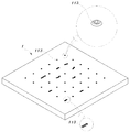
도 3은 본 발명의 일 실시예에 따른 어버트먼트 가공용 자재의 사시도
도 4는 본 발명의 다른 실시예에 따른 어버트먼트 가공용 자재의 사시도
도 5은 본 발명의 실시예에 따른 어버트먼트 가공용 자재 위치고정장치의 상판 사시도
도 6a 내지 도 6c는 본 발명의 실시예에 따른 어버트먼트 가공용 자재 위치고정장치의 하판 사시도
도 7은 본 발명의 실시예에 따른 어버트먼트 가공용 자재 위치고정장치의 고정핀 사시도
도 8은 본 발명의 실시예에 따른 어버트먼트 가공용 자재 위치고정장치의 분해사시도
도 9a 내지 9d는 본 발명의 실시예에 따른 어버트먼트 가공용 자재 위치고정장치의 결합단면도
도 10은 본 발명의 또 다른 실시예에 따른 어버트먼트 가공용 자재의 사시도
도 11는 본 발명의 다른 실시예에 따른 어버트먼트 가공용 자재 위치고정장치의 상판 사시도
도 12는 본 발명의 다른 실시예에 따른 어버트먼트 가공용 자재 위치고정장치의 하판 사시도
도 13 본 발명의 따른 밀링머신의 사시도
도 14는 본 발명의 실시예에 따른 맞춤형 어버트먼트를 가공하는 방법의 블럭도
도 15는 본 발명의 실시예에 따른 맞춤형 어버트먼트를 가공하는 방법의 가공용자재 제공단계에 관한 블럭도1 is a cross-sectional view of a conventional implant
2 is a perspective view of a conventional abutment processed
3 is a perspective view of the abutment processing material according to an embodiment of the present invention
Figure 4 is a perspective view of the material for abutment processing according to another embodiment of the present invention
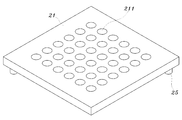
5 is a perspective view of the top plate of the material positioning device for abutment processing according to an embodiment of the present invention
6a to 6c is a bottom perspective view of the material position fixing device for abutment processing according to an embodiment of the present invention
7 is a perspective view of the fixing pin of the material positioning device for abutment processing according to an embodiment of the present invention
8 is an exploded perspective view of the material position fixing device for abutment processing according to an embodiment of the present invention
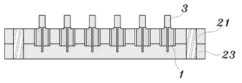
9A to 9D are cross-sectional views of the abutment processing material positioning device according to an embodiment of the present invention.
10 is a perspective view of the abutment processing material according to another embodiment of the present invention
11 is a perspective view of the top plate of the material positioning device for abutment processing according to another embodiment of the present invention
12 is a perspective view of the bottom plate of the material positioning device for abutment processing according to another embodiment of the present invention
13 is a perspective view of a milling machine according to the present invention;
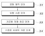
14 is a block diagram of a method for processing a custom abutment in accordance with an embodiment of the present invention.
15 is a block diagram of a processing material providing step of a method for processing a custom abutment according to an embodiment of the present invention.
이하에서는 본 발명에 따른 맞춤형 어버트먼트 가공용 자재에 관하여 바람직한 실시예를 첨부된 도면을 참조하여 상세히 설명한다.Hereinafter, with reference to the accompanying drawings, preferred embodiments of the material for processing a custom abutment according to the present invention will be described in detail.
참고로, 본 발명을 설명함에 있어서 관련된 공지 기능 또는 구성에 대한 구체적인 설명이 본 발명의 핵심을 불필요하게 흐릴 수 있다고 판단될 경우에는 그 상세한 설명을 생략하였다.
For reference, in describing the present invention, when it is determined that a detailed description of related known functions or configurations may unnecessarily obscure the core of the present invention, the detailed description thereof is omitted.
도 3은 본 발명의 일 실시예에 따른 어버트먼트 가공용 자재의 사시도, 도 4는 본 발명의 다른 실시예에 따른 어버트먼트 가공용 자재의 사시도이다.
3 is a perspective view of the abutment processing material according to an embodiment of the present invention, Figure 4 is a perspective view of the abutment processing material according to another embodiment of the present invention.
도 3 내지 4를 참고하면, 어버트먼트 가공용 자재(1)는 중앙을 관통하는 통공(111)과, 상기 통공(111)에 연통되며 픽스츄어와 결합되는 커넥션부(113)를 가진 몸체부(11)를 포함한다.3 to 4, the
상기 몸체부(11)는 추후 곡면 가공을 하여 보철물을 안착시킬 수 있도록 하는 것으로, 상기 몸체부(11)의 외형은 원통형, 직육면체, 다각기둥 등 모두 포함하고, 바람직하게는 원통형이 적합하며, 상기 몸체부에는 중앙을 관통하는 통공(111)과, 상기 통공(111)에 연통되는 커넥션부(113)를 포함한다.The
상기 통공(111)은 상기 몸체부(11)의 중앙부에 관통되도록 형성되며 상하를 관통하도록 형성하여 추후 기술되는 고정핀이 상기 통공(111)의 내부로 인입될 수 있도록 하였다. The through
상기 커넥션부(113)는 픽스츄어가 결합될 수 있도록 형성되는 것으로서, 상기 몸체부(11)의 일단에 일체로 형성되며, 인터널 또는 익스터널타입으로 선택적으로 사용할 수 있으나, 본원발명에서는 상기 통공(111)의 상부에 돌출되도록 익스터널타입으로 형성하는데, 이는 추후 기술되는 가공단계에서 삽입되는 합성수지가 상기 커넥션부(113)로 흘러 커넥션부(113)가 막히는 것을 방지하기 위함이다. 또한, 상기 커넥션부(113)의 내측은 상기 픽스츄어가 인입되는 곳이므로 픽스츄어의 형태에 따라 비원형, 다각형등으로 다양하게 형성될 수 있으나, 본 발명에서는 다각형상으로 형성되어 상기 결합되는 픽스추어가 회전하는 것을 방지하도록 하였다.The
또한, 본 발명의 가공용자재(1)는 도 3에 도시된 바와 같이 각각 독립된 개별적인 낱개의 형태로 형성될 수도 있지만, 도 4에 도시된 바와 같이 하나의 판상에 다수의 커넥션부가 구비된 채 제공되므로 사용자의 필요에 따라 절단하여 사용할 수 있다. 이처럼, 하나의 판에 다수의 커넥션부가 구비되는 경우에는 단일 어버트먼트용 커넥션부 또는 브릿지형 어버트먼트용 커넥션부로 형성될 수 있어서 사용자가 필요에 따라 직접 재단을 하므로서 불필요하게 확장재단하는 것을 방지할 수 있고, 하나의 판상에 여러 형태의 커넥션부가 제공되므로 하나의 판으로도 다양한 어버트먼트를 가공할 수 있어서 다양한 어버트먼트 가공을 위해 다양한 판을 구비할 필요가 없게 되어 원재료를 절감할 수 있고 원가를 절감할 수 있는 효과가 있다.
In addition, the processing material (1) of the present invention may be formed in a separate individual form, respectively, as shown in Figure 3, but as shown in Figure 4 is provided with a plurality of connection parts on one plate Can be cut and used according to the needs of the user. As such, when a plurality of connection parts are provided in one plate, the connection part may be formed as a single abutment connection part or a bridge type abutment connection part, thereby preventing unnecessary extension and cutting while the user directly cuts as needed. Since various connection parts are provided on one plate, it is possible to process a variety of abutments with a single plate, and thus it is not necessary to have a variety of plates for processing a variety of abutments, thereby saving raw materials. It is effective in reducing costs.
도 5는 본 발명의 일 실시예에 따른 어버트먼트 가공용 자재 위치고정장치의 상판 사시도, 도 6a 내지 도 6c는 본 발명의 일 실시예에 따른 어버트먼트 가공용 자재 위치고정장치의 하판 사시도이다.
5 is a top perspective view of the abutment processing material positioning device according to an embodiment of the present invention, Figure 6a to 6c is a bottom perspective view of the abutment processing material positioning device according to an embodiment of the present invention.
상기 도5 내지 도6c를 참조하여, 가공용 자재를 가공함에 앞서 밀링기능을 가진 가공장치 내부에 가공용 자재의 위치를 미리 설정해 줄 수 있도록 형성된 위치고정장치에 대하여 설명하면,Referring to Figures 5 to 6c, prior to processing the processing material will be described with respect to the position fixing device formed so as to set the position of the processing material in advance inside the processing apparatus having a milling function,
상기 위치고정장치(2)는 상기 가공용 자재(1)를 고정할 수 있도록 형성된 상판(21) 및 하판(23)과, 상기 상·하판(21, 23)을 고정시키는 연결수단(25)을 포함한다. The position fixing device 2 includes an
상기 상판(21)은 육면체 등과 같은 형상이며, 상기 가공용 자재(1)가 삽입될 수 있도록 상하부가 관통된 다수개의 삽입통공(211) 및 고정통공(213)을 포함한다.The
상기 삽입통공(211)은 상기 상판(21)의 내부에 다수개가 형성되며, 상기 가공용 자재(1)가 삽입된다. 한편, 상기 삽입통공(211)은 상기 가공용 자재(1)의 직경보다 넓게 형성되어 삽입되는 가공용 자재(1)가 어떤 형상을 띄더라도 가공할 수 있도록 한다.The
상기 고정통공(213)은 대각선의 모서리 부근 등에 형성되고 상기 상·하판(21, 23)의 위치를 설정하여 주며, 추후 서술되는 고정수단이 삽입되도록 형성되어 있다. The fixed through
한편 상기 삽입통공(211) 및 고정통공(213)은 원통형 직육면체형 정육면체형 등과 같이 다양한 형태를 가질 수 있으며, 이는 상기 가공용 자재(1)에 따라 그 형상을 달리 할 수도 있다.Meanwhile, the insertion through
상기 하판(23)은 도6a 내지 도6b에 도시된 바와 같이, 상기 상판(21)과 대향되도록 형성되는데, 고정통공(233)과, 상기 가공용 자재(1)가 안착되는 자재안착홈(235)을 포함한다.The
상기 고정통공(233)은 대각선의 모서리 부근에 형성되며 상기 상판(21)의 고정통공(213)에 연결 관통될 수 있도록 하는데, 이는 상판(21)과 하판(23)의 위치를 설정하여 주며, 추후 서술되는 연결수단(25)이 삽입되도록 충분한 직경과 깊이를 가지고 형성된다. The fixed through
상기 자재안착홈(235)은 상기 상판(21)에 형성된 삽입통공(211)과 같은 위치에 형성되며, 상기 가공용 자재(1)가 안착되어 위치를 결정하고 고정시키는 역할을 한다. 따라서, 상기 자재안착홈(235)의 직경 또는 형상은 가공용 자재(1)에 따라 달라지며, 도 6a에 도시된 바와 같이, 상기 자재안착홈(235)은 한단으로 형성되거나, 도6b에 도시된 바와 같이 직경을 달리한 다단으로 형성될 수 있으며, 다단으로 형성된 경우에는 가공용 자재(1)의 크기에 따라 가공용 자재(1)를 안착시키는 위치를 달리 할 수 있다. 또한, 다단으로 상기 자재안착홈(235)이 형성된 경우에는 자재안착홈(235)의 크기를 달리한 여러개의 하판(23)이 필요치 않으므로 원가절감의 효과도 얻을 수 있다. 한편, 상기 자재안착홈(235)은 상기 가공용자재(1)의 형상에 따라 원형, 타원형, 사각형, 다각형 등으로 다양하게 형성될 수 있으며 본 발명에서는 원형으로 도시하였다.The
상기 연결수단(25)은 도8에 도시된 바와 같이 상기 상·하판(21, 23)의 위치를 설정하여 연결 고정할 수 있도록 바 형태로 하여 상기 상·하판(21, 23)의 고정통공(213, 233)을 관통하여 고정시킨다. 본 발명에서는 바형태으로 형성되어 압입방식으로 끼워넣을 수 있도록 하였으나, 사용자에 따라 나사산을 형성하거나, 다른 형상으로 형성하여 사용할 수 있다.As shown in FIG. 8, the connecting
또한, 상기 연결수단(25)는 도 11 내지 도12에 도시된 바와 같이 상판(21) 또는 하판(23)에 일체로 성형될 수 있으며, 이 경우 상기 연결수단(25)이 상판(21)에 일체로 성형될 경우에는 상판(21)의 고정통공(213)이 형성되지 않고, 반대로 상기 연결수단(25)이 하판에 일체로 성형될 경우에는 하판(23)의 고정통공(233)이 형성되지 않는다.
In addition, the connecting
본 발명의 다른 실시예에 따르면, 도 7에 도시된 바와 같이, 본 발명의 위치고정장치(2)는 고정수단을 추가로 포함할 수 있고, 상기 하판(23)은 고정핀고정공(237)을 추가로 포함한다. 상기 고정핀고정공(237)은 상기 고정수단이 삽입될 수 있도록 하는 구성으로 상기 자재안착홈(235)의 내측 중앙에서 하향으로 함입되어 형성되며, 상기 고정수단의 끝단부의 형상에 따라 나사산 등 다양한 형태를 가질 수 있으며, 본 발명에서는 나사산으로 구성하였다.According to another embodiment of the present invention, as shown in Figure 7, the position fixing device 2 of the present invention may further include a fixing means, the
상기 고정수단은 가공용자재(1)를 하판(21)에 고정시키는 과정에서 흔들림이 없도록 잡아주어 정확한 위치설정을 가능하게 하는 수단이며, 바람직하게는 핀형상을 가진 고정핀(3)이 적합하며, 상기 고정핀(3)은 손잡이(31)와, 상기 손잡이(31)의 하부에 형성하는 지지대(32)와, 상기 지지대(32)의 하부에 형성된 나사산(33)을 포함한다. The fixing means is a means for enabling accurate positioning by holding the processing material (1) in the process of fixing to the
상기 손잡이(31)는 상기 하판(23)의 고정핀고정공(237)에 고정핀(3)의 끝단에 형성된 나사산(33)를 결합 시 손쉽게 체결할 수 있도록 형성된 것으로서, 본발명에서는 원통형으로 형성하였으나, 사용자의 편의에 따라 그 형상을 달리 할 수 있다. The
상기 지지대(32)는 상기 손잡이(31)의 하부에 형성되며, 상기 가공용 자재(1)의 내부에 형성된 통공(111)에 관통되도록 형성하는 것으로 지지대(32)의 굵기 및 길이는 상기 가공용 자재(1)의 통공(111)의 크기에 따라 달라진다.The
상기 나사산(33)는 상기 하판(23)의 고정핀고정공(237)과 연결 고정되도록 형성되며, 상기 나사산은 사용자의 사용에 따라 나사식으로 체결하거나, 압입방식으로 고정시킬 수 있으므로 사용자의 편의에 따라 그 형태를 다양하게 할수 있는데, 본 발명에서는 나사산을 형성하였다.The
또한, 본 발명의 또 다른 실시예에 따르면 도 6c에 도시된 바와 같이, 상기 하판(23)은 상기 고정핀고정공(237) 대신에 고정핀고정돌기(239)를 포함하여 형성될 수도 있다.In addition, according to another embodiment of the present invention, as shown in Figure 6c, the
상기 고정핀고정돌기(239)는 상기 하판(23)에서 상향으로 돌출되어 형성되며 상기 고정핀고정돌기(239)가 상기 가공용자재(1)의 통공(111)에 삽입되어 상기 가공용 자재(1)를 고정시키게 된다.
The fixing
도 8은 본 발명의 일 실시예에 따른 어버트먼트 가공용 자재 위치고정장치의 분해사시도, 도9a 내지 9d는 본 발명의 일 실시예에 따른 어버트먼트 가공용 자재 위치고정장치의 결합단면도이다.8 is an exploded perspective view of the abutment processing material positioning device according to an embodiment of the present invention, Figures 9a to 9d is a combined cross-sectional view of the abutment processing material positioning device according to an embodiment of the present invention.
도 8 내지 도 9를 참조하면, 상기 위치고정장치(2)의 사용방법은 상기 하판(23)의 자재안착홈(235) 상부에 가공용 자재(1)를 위치시킨 다음, 하판(23)의 고정핀고정공(237)에 상기 가공용 자재(1)를 관통시킨 상기 고정핀(3)을 삽입하여 가공용 자재(1)를 고정시킨다. 하판(23), 가공용 자재(1) 및 고정핀(3)의 순으로 결합한 상부에 상기 상판(21)을 위치시키는데, 상기 하판(23)과 상판(21)의 대각선에 위치한 고정통공(213, 233)이 서로 맞물리도록 위치시켜 연결수단(25)으로 고정시킨다. 8 to 9, the method of using the position fixing device 2 includes placing the
또한, 도9b에 도시된 바와 같이, 고정된 가공용자재(1)와 위치고정장치(2)의 틈새에 합성수지(D)를 채워 넣은후, 도9c에 도시된 바와 같이, 시간이 경과된 후에 상기 합성수지(D)가 굳게 되면 상기 연결수단(25) 및 고정핀(3)을 제거한다.In addition, as shown in Figure 9b, after filling the synthetic resin (D) in the gap between the fixed processing material (1) and the position fixing device (2), as shown in Figure 9c, after the time has elapsed When the synthetic resin (D) is hardened, the connecting
상기 연결수단(25) 및 고정핀(3)을 제거한 후에는 하판(23)을 제거하므로서 도9d에 도시된 바와 같이 상기 합성수지(D)가 결합된 상판(21)과 가공용 자재(1)만 남긴 후 밀링가공을 하는 장치 내부의 척에 고정시킨다. After removing the connecting
상기 가공용 자재 위치고정장치는 밀링가공을 하는 장치를 이용하여 가공용 자재를 가공을 하게 되는데 이때 미리 정확한 위치에 상기 가공용 자재의 위치를 잡아줌으로서 다수개의 자재를 대량 가공할 수 있고, 하나하나 위치를 조정하지 않고, 각각의 치수대로 다듬질하기 위해서 필요한 고도의 숙련도도 필요치 않으므로 가공시간이 절약되는 장점이 있는 것이다.
The processing material position fixing device is to process the processing material using a milling device, at this time, by holding the position of the processing material in the correct position in advance, it is possible to process a large number of materials, one by one Without the need to adjust the level of skill required to trim each dimension, there is an advantage that the processing time is saved.
도 10는 본 발명의 다른 실시예에 따른 어버트먼트 가공용 자재의 사시도이고, 이하에서는 도 10을 참조하여 가공용 자재(1)에 관한 다른 실시예를 살펴본다. FIG. 10 is a perspective view of an abutment processing material according to another embodiment of the present invention. Hereinafter, another embodiment of the
도 10에 도시된 본 발명의 다른 실시예에 따른 어버트먼트 가공용 자재는 앞서 살펴본 상기 일 실시예의 구성과 동일하나 어버트먼트 가공용 자재(1)의 커넥션부(13) 상부에 어버트먼트 스크류(115)를 일체형으로 형성하는 것을 특징으로 한다.Abutment processing material according to another embodiment of the present invention shown in Figure 10 is the same as the configuration of the embodiment described above, but the abutment screw (top) of the connection portion 13 of the abutment processing material (1) 115) is formed in one piece.
상기 어버트먼트 스크류(115)를 제외한 가공용 자재(1)의 구성은 상기 실시예와 동일하므로 그에 대한 기재는 생략하였다.Since the configuration of the
상기 어버트먼트 스크류(115)는 상기 커넥션부와 일체로 성형되는데 상기 커넥션부에 삽입되는 픽스추어를 연결·고정시킬 수 있도록 한다. The
또한, 본 발명의 다른 실시예에 따르면 도시되지는 않았지만 몸체부(11)의 내부에 통공(111)을 형성하는 대신 어버트먼트 스크류(115)의 대향되는 말단에 돌기를 형성하여 돌기가 하판(23)의 고정핀고정공(237)에 삽입될 수도 있다.
Further, although not shown, according to another embodiment of the present invention, instead of forming the through-
도13은 도 13 본 발명의 따른 밀링머신의 사시도, 도 14는 본 발명의 실시예에 따른 맞춤형 어버트먼트를 가공하는 방법의 블럭도, 도 15는 본 발명의 실시예에 따른 맞춤형 어버트먼트를 가공하는 방법의 가공용자재 제공단계에 관한 블럭도이다.13 is a perspective view of a milling machine according to the present invention, Figure 14 is a block diagram of a method for processing a custom abutment according to an embodiment of the present invention, Figure 15 is a custom abutment according to an embodiment of the present invention Is a block diagram of a step for providing a material for processing of the process.
도 14 내지 도15을 참조하면 맞춤형 어버트먼트를 가공하는 방법은 모형제작단계(S1), 모형스캔단계(S2), 가공용 자재 제공단계(S3) 및 가공용 자재의 가공단계(S4)를 포함한다.Referring to FIGS. 14 to 15, a method of processing a custom abutment includes a model manufacturing step S1, a model scanning step S2, a processing material providing step S3, and a processing material processing step S4. .
상기 모형제작단계(S1)는 시술하고자 하는 환자의 구강상태에 따라 어버트먼트의 모형을 석고와 같은 재료로 모형을 제작한다.In the model production step (S1), a model of the abutment is manufactured from a plaster-like material according to the oral condition of the patient to be treated.
상기 모형스캔단계(S2)는 상기 모형제작단계(S1)에서 제작된 어버트먼트 모형을 3차원 스캐너로 스캔하는 것을 말하며, 상기 스캔된 영상을 바탕으로 후술하는 가공용자재의 가공단계에서 가공용자재를 밀링가공을 하는 장치를 사용하여 가공하게 된다.The model scanning step (S2) refers to scanning the abutment model produced in the model production step (S1) with a three-dimensional scanner, the processing material in the processing step of the processing material to be described later based on the scanned image It is processed using a milling device.
상기 가공용자재 제공단계(S3)는 도15에 도시된 바와 같이, 위치설정단계(S31), 몰딩단계(S32), 하판제거단계(S33) 및 상판고정단계(S34)를 포함한다.As illustrated in FIG. 15, the processing material providing step S3 includes a positioning step S31, a molding step S32, a lower plate removing step S33, and an upper plate fixing step S34.
상기 위치설정단계(S31)는 상판(21)과 하판(23)의 사이에 가공용 자재(1)를 위치시켜 고정핀 및 연결수단으로 가공용 자재의 위치 설정 및 고정시킨다.In the positioning step S31, the
상기 몰딩단계(S32)는 상기 위치설정단계(S31)에서 고정된 가공용자재(1)와 위치고정장치(2)의 틈새에 합성수지(D)를 주입한다.In the molding step S32, a synthetic resin D is injected into a gap between the
상기 하판제거단계(S33)는 상기 몰딩단계(S32)에 주입한 합성수지(D)가 일정시간이 경과되어 굳으면 상기 위치설정단계(S31)에서 고정시킨 고정핀 및 연결수단을 제거한 후, 하판을 제거한다.The lower plate removing step (S33), if the synthetic resin (D) injected in the molding step (S32) is hardened after a certain time has elapsed, after removing the fixing pin and the connecting means fixed in the positioning step (S31), the lower plate Remove
상기 상판 고정단계(S34)는 상기 하판제거단계(S33)를 거치고 남은 상판(21) 및 가공용 자재(1)를 밀링가공을 하는 장치 내부에 형성된 척에 고정시킨다.The upper plate fixing step S34 fixes the remaining
상기 가공용자재 가공단계(S4)는 상기 가공용자재 제공단계(S3)를 통해 밀링머신 척에 고정되어 있는 가공용자재를 상기 모형스캔단계에서 스캔한 형상에 따라 곡면가공하는 것을 말하는데, 도13에 도시하고 있는 밀링머신은 당분야에서 통상을 지식을 가진자가 알 수 있을 정도로 널리 알려진 기술이므로 본 발명에서는 자세한 설명은 기재하지 않았다.
The processing material processing step (S4) refers to processing the surface of the processing material fixed to the milling machine chuck through the processing material providing step (S3) according to the shape scanned in the model scanning step, as shown in FIG. Since the milling machine is a well known technique that can be known to those skilled in the art, the detailed description is not described in the present invention.
이상에서 설명한 본 발명은 전술한 실시예 및 첨부된 도면에 한정되는 것이 아니고, 본 발명의 기술적 사상을 벗어나지 않는 범위 내에서 여러 가지 치환, 변형, 및 변경이 가능하다는 것은 본 발명이 속하는 기술 분야에서 통상의 지식을 가진 자에게 있어 명백할 것이다.The present invention described above is not limited to the above-described embodiments and the accompanying drawings, and various substitutions, modifications, and changes are possible in the technical field of the present invention without departing from the technical spirit of the present invention. It will be clear to those of ordinary knowledge.
1 : 가공용 자재 2 :위치고정장치
3 : 고정핀 11 : 몸체부
21 : 상판 23 : 하판
25 : 연결수단 31 : 손잡이
32 : 지지대 33 : 나사산
111: 통공 113 : 커넥션부
115 : 어버트먼트 스크류 211 : 삽입통공
213, 233 : 고정통공 235 : 자재안착홈
237 : 고정핀고정공 239 : 고정핀고정돌기
A : 보철물 B : 어버트먼트
B1 : 종래의 상부지지대 B2 : 종래의 커넥션부
C : 픽스츄어 D : 합성수지1: Processing material 2: Position fixing device
3: fixing pin 11: body
21: top plate 23: bottom plate
25 connection means 31 handle
32: support 33: thread
111: through-hole 113: connection part
115: abutment screw 211: insertion hole
213, 233: fixed through hole 235: material seating groove
237: fixing pin fixing hole 239: fixing pin fixing protrusion
A: Prosthesis B: Abutment
B1: conventional upper support B2: conventional connection part
C: Fixture D: Synthetic Resin
Claims (4)
중앙을 관통하는 통공을 가진 몸체부를 포함하며,
상기 몸체부는 그 일단에 상기 통공과 연통되며 다양한 픽스츄어와 결합되는 커넥션부를 일체로 형성하고,
상기 커넥션부는 상기 몸체부의 일단에서 외부로 돌출되어 커넥션부의 일단이 몸체부의 일단보다 외부로 돌출되도록 형성되는 것을 특징으로 하는 맞춤형 어버트먼트 가공용 자재.In the abutment processing material used to process a custom abutment suitable for the patient's dental structure,
It includes a body having a through-hole through the center,
The body portion integrally forms a connection portion communicating with the through hole at one end thereof and coupled with various fixtures.
The connection portion protrudes outward from one end of the body portion, wherein the one end of the connection portion is formed so as to protrude outward than one end of the body portion.
상기 커넥션부는 커넥션부 상부에 어버트먼트 스크류가 일체로 형성되는 것을 특징으로 하는 맞춤형 어버트먼트 가공용 자재.The method of claim 1,
The abutment processing material, characterized in that the abutment screw is integrally formed on the connection portion.
상기 커넥션부가 다양한 형상의 가공용 자재는 단일의 어버트먼트용 커넥션부 또는 브릿지형 어버트먼트용 커넥션부가 하나의 판상에 다양하게 구성됨을 특징으로 하는 맞춤형 어버트먼트 가공용 자재.The method according to claim 1 or 2,
The material for processing a variety of shapes of the connection portion is a custom abutment processing material, characterized in that a single abutment connection portion or a bridge-type abutment connection portion is configured on a single plate.
Priority Applications (1)
| Application Number | Priority Date | Filing Date | Title |
|---|---|---|---|
| KR1020100024595A KR101035503B1 (en) | 2010-03-19 | 2010-03-19 | A Raw Materials of Customized Abutment |
Applications Claiming Priority (1)
| Application Number | Priority Date | Filing Date | Title |
|---|---|---|---|
| KR1020100024595A KR101035503B1 (en) | 2010-03-19 | 2010-03-19 | A Raw Materials of Customized Abutment |
Related Parent Applications (1)
| Application Number | Title | Priority Date | Filing Date |
|---|---|---|---|
| KR1020080107314A Division KR100979196B1 (en) | 2008-10-30 | 2008-10-30 | Position fixing device of customized abutment processing material and abutment processing method using the same |
Publications (2)
| Publication Number | Publication Date |
|---|---|
| KR20100048968A KR20100048968A (en) | 2010-05-11 |
| KR101035503B1 true KR101035503B1 (en) | 2011-05-20 |
Family
ID=42275592
Family Applications (1)
| Application Number | Title | Priority Date | Filing Date |
|---|---|---|---|
| KR1020100024595A Ceased KR101035503B1 (en) | 2010-03-19 | 2010-03-19 | A Raw Materials of Customized Abutment |
Country Status (1)
| Country | Link |
|---|---|
| KR (1) | KR101035503B1 (en) |
Families Citing this family (8)
| Publication number | Priority date | Publication date | Assignee | Title |
|---|---|---|---|---|
| KR101093512B1 (en) | 2011-05-26 | 2011-12-13 | 염명희 | Abutment material for implant |
| WO2013012113A1 (en) * | 2011-07-21 | 2013-01-24 | 주식회사 덴트컴 | Material for fabricating a custom abutment, apparatus for fixing the position of the material, and method for fabricating the custom abutment using same |
| WO2015189648A2 (en) * | 2014-06-13 | 2015-12-17 | Vergoullis Ioannis | Abutments and impression posts for dental implant procedures |
| GR1008855B (en) * | 2014-12-16 | 2016-09-27 | Ιωαννης Αντωνιου Βεργουλλης | Custom implant impression posts being of the straight open type, straight closed type and inclined type - independent accessories for the realisation and verification of implants impression |
| GR20150100111A (en) * | 2015-03-12 | 2016-10-20 | Ιωαννης Αντωνιου Βεργουλλης | Straight, inclined, individualised and potentially adjustable abutments & dental implant inpression posts - impression molds for mass production of same |
| EP3474772B1 (en) | 2016-06-24 | 2020-04-22 | VP Innovato Holdings Ltd. | Dental tools system and method |
| GR20170100383A (en) | 2017-08-21 | 2019-04-22 | Vp Innovato Holdings Ltd | Dental abutment core and method for manufacturing a dental abutment |
| GR20200100312A (en) | 2020-06-04 | 2022-01-13 | Ιωαννης Αντωνιου Βεργουλλης | SCANNING SYSTEM SYSTEM AND METHOD |
Citations (3)
| Publication number | Priority date | Publication date | Assignee | Title |
|---|---|---|---|---|
| KR20030029978A (en) * | 2000-09-25 | 2003-04-16 | 액테리온 파마슈티칼 리미티드 | Substitued amino-aza-cycloalkanes useful aganist malaria |
| KR200329978Y1 (en) | 2003-07-11 | 2003-10-17 | 주식회사 오스템 | Cap for Dental Implant |
| KR100842096B1 (en) | 2006-12-07 | 2008-06-30 | 김대현 | Block body with connecting structure in dental implant abutment and superstructure and manufacturing method thereof |
-
2010
- 2010-03-19 KR KR1020100024595A patent/KR101035503B1/en not_active Ceased
Patent Citations (3)
| Publication number | Priority date | Publication date | Assignee | Title |
|---|---|---|---|---|
| KR20030029978A (en) * | 2000-09-25 | 2003-04-16 | 액테리온 파마슈티칼 리미티드 | Substitued amino-aza-cycloalkanes useful aganist malaria |
| KR200329978Y1 (en) | 2003-07-11 | 2003-10-17 | 주식회사 오스템 | Cap for Dental Implant |
| KR100842096B1 (en) | 2006-12-07 | 2008-06-30 | 김대현 | Block body with connecting structure in dental implant abutment and superstructure and manufacturing method thereof |
Also Published As
| Publication number | Publication date |
|---|---|
| KR20100048968A (en) | 2010-05-11 |
Similar Documents
| Publication | Publication Date | Title |
|---|---|---|
| KR101035503B1 (en) | A Raw Materials of Customized Abutment | |
| KR101334524B1 (en) | Multi-jig for processing adjustable abutment fixing apparatus | |
| EP3380036B1 (en) | Plate for production of a dental implant and/or artificial prosthesis | |
| ES2274172T3 (en) | PROLONGATION PART FOR A DENTAL IMPLANT, TRANSFER HELP AND PROCEDURE TO ESTABLISH A BASE FOR A RETAINING ELEMENT. | |
| JP6244022B2 (en) | Artificial teeth | |
| US8777617B2 (en) | Dental abutment | |
| BR112012018070B1 (en) | abutment for a dental implant and combination of a dental implant and abutment | |
| JPWO2015125573A1 (en) | Artificial teeth | |
| KR101889014B1 (en) | Work for abutment manufacturing | |
| US20200016709A1 (en) | Method for correcting an axial position of a workpiece support | |
| KR100979196B1 (en) | Position fixing device of customized abutment processing material and abutment processing method using the same | |
| US20160278893A1 (en) | Method and device for securing prefabricated prosthetic teeth | |
| KR101813877B1 (en) | Double coupling zig with guide | |
| JP2004514541A (en) | Retainers for models of dentures or foundation frames | |
| CN103857357B (en) | For inserting the laboratory simulation body with location division in the plastic pattern with pairing location division | |
| US20200015941A1 (en) | Connection structure for dental abutment | |
| CN107278143B (en) | Implant analogs with transverse components | |
| JP4823838B2 (en) | Abutment model holder | |
| JP2007229127A (en) | Block holder for dental prosthesis | |
| JP7035165B2 (en) | How to place blanks | |
| CN111683619B (en) | Improved fixation pin support for dentures and method of making the same | |
| KR101629960B1 (en) | Dental block jig for manufacturing crown of dental and manufacturing method thereof | |
| CN111405880B (en) | Dental restoration moulding block and method for manufacturing a dental restoration component from a dental restoration moulding block | |
| JP6409145B1 (en) | Abutment material for tailor-made implants and jig for tooth processing | |
| KR20100100653A (en) | Artificial tooth processing catch |
Legal Events
| Date | Code | Title | Description |
|---|---|---|---|
| A107 | Divisional application of patent | ||
| PA0107 | Divisional application |
Comment text: Divisional Application of Patent Patent event date: 20100319 Patent event code: PA01071R01D Filing date: 20081030 Application number text: 1020080107314 |
|
| PG1501 | Laying open of application | ||
| A201 | Request for examination | ||
| PA0201 | Request for examination |
Patent event code: PA02012R01D Patent event date: 20101228 Comment text: Request for Examination of Application Patent event code: PA02011R04I Patent event date: 20100319 Comment text: Divisional Application of Patent |
|
| E902 | Notification of reason for refusal | ||
| PE0902 | Notice of grounds for rejection |
Comment text: Notification of reason for refusal Patent event date: 20110210 Patent event code: PE09021S01D |
|
| E701 | Decision to grant or registration of patent right | ||
| PE0701 | Decision of registration |
Patent event code: PE07011S01D Comment text: Decision to Grant Registration Patent event date: 20110418 |
|
| GRNT | Written decision to grant | ||
| PR0701 | Registration of establishment |
Comment text: Registration of Establishment Patent event date: 20110512 Patent event code: PR07011E01D |
|
| PR1002 | Payment of registration fee |
Payment date: 20110513 End annual number: 3 Start annual number: 1 |
|
| PG1601 | Publication of registration | ||
| FPAY | Annual fee payment |
Payment date: 20140226 Year of fee payment: 4 |
|
| PR1001 | Payment of annual fee |
Payment date: 20140226 Start annual number: 4 End annual number: 4 |
|
| FPAY | Annual fee payment |
Payment date: 20150512 Year of fee payment: 5 |
|
| PR1001 | Payment of annual fee |
Payment date: 20150512 Start annual number: 5 End annual number: 5 |
|
| FPAY | Annual fee payment |
Payment date: 20160512 Year of fee payment: 6 |
|
| PR1001 | Payment of annual fee |
Payment date: 20160512 Start annual number: 6 End annual number: 6 |
|
| FPAY | Annual fee payment |
Payment date: 20170515 Year of fee payment: 7 |
|
| PR1001 | Payment of annual fee |
Payment date: 20170515 Start annual number: 7 End annual number: 7 |
|
| FPAY | Annual fee payment |
Payment date: 20180515 Year of fee payment: 8 |
|
| PR1001 | Payment of annual fee |
Payment date: 20180515 Start annual number: 8 End annual number: 8 |
|
| J202 | Request for trial for correction [limitation] | ||
| PJ0202 | Trial for correction |
Comment text: Request for Trial Patent event date: 20190226 Patent event code: PJ02022R01D Comment text: Registration of Establishment Patent event date: 20110512 Patent event code: PJ02021E01I Appeal kind category: Correction Decision date: 20190321 Request date: 20190226 Appeal identifier: 2019105000016 |
|
| J301 | Trial decision |
Free format text: TRIAL NUMBER: 2019105000016; TRIAL DECISION FOR CORRECTION REQUESTED 20190226 Effective date: 20190321 |
|
| PJ1301 | Trial decision |
Patent event code: PJ13011S03D Patent event date: 20190321 Comment text: Trial Decision on Correction (Patent, Utility Model) Appeal kind category: Correction Request date: 20190226 Decision date: 20190321 Appeal identifier: 2019105000016 |
|
| G170 | Re-publication after modification of scope of protection [patent] | ||
| PG1701 | Publication of correction |
Publication date: 20190403 |
|
| FPAY | Annual fee payment |
Payment date: 20190510 Year of fee payment: 9 |
|
| PR1001 | Payment of annual fee |
Payment date: 20190510 Start annual number: 9 End annual number: 9 |
|
| J204 | Request for invalidation trial [patent] | ||
| PJ0204 | Invalidation trial for patent |
Patent event date: 20190911 Comment text: Request for Trial Patent event code: PJ02042R01D Patent event date: 20110512 Comment text: Registration of Establishment Patent event code: PJ02041E01I Appeal kind category: Invalidation Request date: 20190911 Decision date: 20200226 Appeal identifier: 2019100002927 |
|
| J301 | Trial decision |
Free format text: TRIAL NUMBER: 2019100002927; TRIAL DECISION FOR INVALIDATION REQUESTED 20190911 Effective date: 20200226 |
|
| PJ1301 | Trial decision |
Patent event code: PJ13011S05D Patent event date: 20200226 Comment text: Trial Decision on Invalidation (Patent, Utility Model, Industrial Design) Appeal kind category: Invalidation Request date: 20190911 Decision date: 20200226 Appeal identifier: 2019100002927 |
|
| J2X1 | Appeal (before the patent court) |
Free format text: TRIAL NUMBER: 2020200003027; INVALIDATION |
|
| PJ2001 | Appeal |
Patent event date: 20200226 Comment text: Trial Decision on Invalidation (Patent, Utility Model, Industrial Design) Patent event code: PJ20011S05I Patent event date: 20190321 Comment text: Trial Decision on Correction (Patent, Utility Model) Patent event code: PJ20011S03I Appeal kind category: Invalidation Decision date: 20200820 Appeal identifier: 2020200003027 Request date: 20200327 |
|
| FPAY | Annual fee payment |
Payment date: 20200513 Year of fee payment: 10 |
|
| PR1001 | Payment of annual fee |
Payment date: 20200513 Start annual number: 10 End annual number: 10 |
|
| J2X2 | Appeal (before the supreme court) |
Free format text: TRIAL NUMBER: 2020300011387; APPEAL BEFORE THE SUPREME COURT FOR INVALIDATION |
|
| PJ2002 | Appeal before the supreme court |
Comment text: Trial Decision on Invalidation (Patent, Utility Model, Industrial Design) Patent event date: 20200226 Patent event code: PJ20021S05I Comment text: Trial Decision on Correction (Patent, Utility Model) Patent event date: 20190321 Patent event code: PJ20021S03I Request date: 20200917 Appeal identifier: 2020300011387 Appeal kind category: Invalidation Decision date: 20201224 |
|
| EXTG | Ip right invalidated | ||
| PC2102 | Extinguishment |
Termination category: Others Termination date: 20210105 |
|
| J302 | Written judgement (patent court) |
Free format text: TRIAL NUMBER: 2020200003027; JUDGMENT (PATENT COURT) FOR INVALIDATION REQUESTED 20200327 Effective date: 20200820 |
|
| PJ1302 | Judgment (patent court) |
Patent event date: 20210104 Comment text: Written Judgment (Patent Court) Patent event code: PJ13021S01D Request date: 20200327 Decision date: 20200820 Appeal identifier: 2020200003027 Appeal kind category: Invalidation |