KR101028617B1 - Implant Abutments - Google Patents
Implant Abutments Download PDFInfo
- Publication number
- KR101028617B1 KR101028617B1 KR1020100091407A KR20100091407A KR101028617B1 KR 101028617 B1 KR101028617 B1 KR 101028617B1 KR 1020100091407 A KR1020100091407 A KR 1020100091407A KR 20100091407 A KR20100091407 A KR 20100091407A KR 101028617 B1 KR101028617 B1 KR 101028617B1
- Authority
- KR
- South Korea
- Prior art keywords
- prosthetic
- coupling portion
- groove
- fixture
- prosthesis
- Prior art date
- Legal status (The legal status is an assumption and is not a legal conclusion. Google has not performed a legal analysis and makes no representation as to the accuracy of the status listed.)
- Active
Links
- 239000007943 implant Substances 0.000 title claims abstract description 20
- 230000008878 coupling Effects 0.000 claims abstract description 89
- 238000010168 coupling process Methods 0.000 claims abstract description 89
- 238000005859 coupling reaction Methods 0.000 claims abstract description 89
- 238000000034 method Methods 0.000 claims 4
- 230000035876 healing Effects 0.000 abstract description 4
- 210000000988 bone and bone Anatomy 0.000 description 2
- RTAQQCXQSZGOHL-UHFFFAOYSA-N Titanium Chemical compound [Ti] RTAQQCXQSZGOHL-UHFFFAOYSA-N 0.000 description 1
- 239000004053 dental implant Substances 0.000 description 1
- 229910052719 titanium Inorganic materials 0.000 description 1
- 239000010936 titanium Substances 0.000 description 1
Images



Classifications
-
- A—HUMAN NECESSITIES
- A61—MEDICAL OR VETERINARY SCIENCE; HYGIENE
- A61C—DENTISTRY; APPARATUS OR METHODS FOR ORAL OR DENTAL HYGIENE
- A61C8/00—Means to be fixed to the jaw-bone for consolidating natural teeth or for fixing dental prostheses thereon; Dental implants; Implanting tools
- A61C8/0048—Connecting the upper structure to the implant, e.g. bridging bars
- A61C8/005—Connecting devices for joining an upper structure with an implant member, e.g. spacers
-
- A—HUMAN NECESSITIES
- A61—MEDICAL OR VETERINARY SCIENCE; HYGIENE
- A61C—DENTISTRY; APPARATUS OR METHODS FOR ORAL OR DENTAL HYGIENE
- A61C8/00—Means to be fixed to the jaw-bone for consolidating natural teeth or for fixing dental prostheses thereon; Dental implants; Implanting tools
- A61C8/0048—Connecting the upper structure to the implant, e.g. bridging bars
- A61C8/0077—Connecting the upper structure to the implant, e.g. bridging bars with shape following the gingival surface or the bone surface
-
- A—HUMAN NECESSITIES
- A61—MEDICAL OR VETERINARY SCIENCE; HYGIENE
- A61C—DENTISTRY; APPARATUS OR METHODS FOR ORAL OR DENTAL HYGIENE
- A61C8/00—Means to be fixed to the jaw-bone for consolidating natural teeth or for fixing dental prostheses thereon; Dental implants; Implanting tools
- A61C8/0048—Connecting the upper structure to the implant, e.g. bridging bars
- A61C8/005—Connecting devices for joining an upper structure with an implant member, e.g. spacers
- A61C8/0066—Connecting devices for joining an upper structure with an implant member, e.g. spacers with positioning means
-
- A—HUMAN NECESSITIES
- A61—MEDICAL OR VETERINARY SCIENCE; HYGIENE
- A61C—DENTISTRY; APPARATUS OR METHODS FOR ORAL OR DENTAL HYGIENE
- A61C8/00—Means to be fixed to the jaw-bone for consolidating natural teeth or for fixing dental prostheses thereon; Dental implants; Implanting tools
- A61C8/0048—Connecting the upper structure to the implant, e.g. bridging bars
- A61C8/005—Connecting devices for joining an upper structure with an implant member, e.g. spacers
- A61C8/0074—Connecting devices for joining an upper structure with an implant member, e.g. spacers with external threads
-
- A—HUMAN NECESSITIES
- A61—MEDICAL OR VETERINARY SCIENCE; HYGIENE
- A61C—DENTISTRY; APPARATUS OR METHODS FOR ORAL OR DENTAL HYGIENE
- A61C8/00—Means to be fixed to the jaw-bone for consolidating natural teeth or for fixing dental prostheses thereon; Dental implants; Implanting tools
- A61C8/008—Healing caps or the like
-
- A—HUMAN NECESSITIES
- A61—MEDICAL OR VETERINARY SCIENCE; HYGIENE
- A61C—DENTISTRY; APPARATUS OR METHODS FOR ORAL OR DENTAL HYGIENE
- A61C8/00—Means to be fixed to the jaw-bone for consolidating natural teeth or for fixing dental prostheses thereon; Dental implants; Implanting tools
- A61C8/0048—Connecting the upper structure to the implant, e.g. bridging bars
- A61C8/005—Connecting devices for joining an upper structure with an implant member, e.g. spacers
- A61C8/006—Connecting devices for joining an upper structure with an implant member, e.g. spacers with polygonal positional means, e.g. hexagonal or octagonal
-
- A—HUMAN NECESSITIES
- A61—MEDICAL OR VETERINARY SCIENCE; HYGIENE
- A61C—DENTISTRY; APPARATUS OR METHODS FOR ORAL OR DENTAL HYGIENE
- A61C8/00—Means to be fixed to the jaw-bone for consolidating natural teeth or for fixing dental prostheses thereon; Dental implants; Implanting tools
- A61C8/0048—Connecting the upper structure to the implant, e.g. bridging bars
- A61C8/005—Connecting devices for joining an upper structure with an implant member, e.g. spacers
- A61C8/0068—Connecting devices for joining an upper structure with an implant member, e.g. spacers with an additional screw
Landscapes
- Health & Medical Sciences (AREA)
- Oral & Maxillofacial Surgery (AREA)
- Orthopedic Medicine & Surgery (AREA)
- Dentistry (AREA)
- Epidemiology (AREA)
- Life Sciences & Earth Sciences (AREA)
- Animal Behavior & Ethology (AREA)
- General Health & Medical Sciences (AREA)
- Public Health (AREA)
- Veterinary Medicine (AREA)
- Dental Prosthetics (AREA)
Abstract
본 발명은 임플란트용 어버트먼트에 대한 것으로서, 더욱 상세하게는 스크류가 풀리는 것을 방지할 수 있는 투피스 타입의 임플란트용 어버트먼트에 대한 것이다.
본 발명에 따른 어버트먼트는 몸체부재와, 머리부재를 포함한다. 상기 몸체부재는 잇몸결합부와, 제1보철결합부를 구비한다. 상기 잇몸결합부에는 잇몸이 결합된다. 그리고 제1보철결합부는 보철물이 장착되기 위하여 상기 잇몸결합부의 상부에 형성되며 외주면에서 상부에서부터 하부로 제1보철홈이 형성된다. 그리고 상기 몸체부제는 축방향으로 관통된다. 상기 머리부재는 제2보철결합부와 나사부를 구비한다. 상기 제2보철결합부는 보철물이 장착될 수 있게 상기 제1보철결합부의 상부에 위치하며 상기 제1보철홈을 덮지 않도록 형성되며 외주면에서 상부에서부터 하부까지 제2보철홈이 형성된다. 상기 나사부는 상기 몸체부재를 관통한 후 상기 픽스쳐에 삽입되어 나사결합할 수 있도록 상기 제2보철결합부에서 연장된다.
본 발명에 의하면 제1보철결합부와 제2보철결합부의 외주면에 각각 제1보철홈과 제2보철홈을 형성시키고 제2보철결합부가 제1보철홈을 덮지 않도록 제2보철결합부의 외경의 크기를 작게 함으로써, 보철물에 외력이 가해지더라도 제2보철결합부와 픽스쳐의 나사결합이 풀리는 것을 방지할 수 있다.
또한, 본 발명에 의하면 제1보철결합부와 제2보철결합부의 외주면에 제1그루브와 제2그루브가 형성됨으로 인하여 보철물이 장착된 경우 보철물의 유지력을 증가시킬 수 있고, 힐링캡으로 사용이 가능하다.The present invention relates to an implant abutment, and more particularly, to an abutment for a two piece type implant which can prevent the screw from loosening.
The abutment according to the present invention includes a body member and a head member. The body member has a gum coupling portion and a first prosthetic coupling portion. The gum is coupled to the gum coupling part. The first prosthetic coupling portion is formed on the gum coupling portion to mount the prosthesis, and a first prosthetic groove is formed from the top to the bottom on the outer circumferential surface thereof. The body part is penetrated in the axial direction. The head member has a second prosthetic coupling portion and a screw portion. The second prosthetic coupling portion is positioned above the first prosthetic coupling portion so that the prosthesis can be mounted, and is formed so as not to cover the first prosthetic groove. The screw portion extends from the second prosthetic coupling portion to penetrate the body member and to be inserted into the fixture and screwed therein.
According to the present invention, the first prosthetic groove and the second prosthetic groove are formed on the outer circumferential surfaces of the first prosthetic coupling portion and the second prosthetic coupling portion, respectively, and the size of the outer diameter of the second prosthetic coupling portion does not cover the first prosthetic coupling portion. By reducing the size, it is possible to prevent the screwing of the second prosthetic coupling portion and the fixture from being loosened even when an external force is applied to the prosthesis.
Further, according to the present invention, since the first groove and the second groove are formed on the outer circumferential surfaces of the first prosthetic coupling portion and the second prosthetic coupling portion, when the prosthesis is mounted, the holding force of the prosthesis can be increased, and it can be used as a healing cap. Do.
Description
본 발명은 임플란트용 어버트먼트에 대한 것으로서, 더욱 상세하게는 스크류가 풀리는 것을 방지할 수 있는 투피스 타입의 임플란트용 어버트먼트에 대한 것이다.The present invention relates to an implant abutment, and more particularly, to an abutment for a two piece type implant which can prevent the screw from loosening.
치아용 임플란트(dental implant)는 부분적 또는 전체적으로 치아가 상실된 부위에 인공 치근을 심어 치조골에 유착시키고, 그 인공 치근에 치아 보철(prosthesis or crown)을 고정하여 형성된 인공 치아 구조 또는 이러한 치과 시술방법을 의미한다. 일반적으로 임플란트는 티타늄으로 구성된 픽스쳐(fixture)와 픽스쳐 상에 고정되는 어버트먼트(abutment)로 구성된다.Dental implant refers to an artificial tooth structure formed by fixing artificial prosthesis to the alveolar bone by partially or totally missing teeth and fixing prosthesis or crown to the artificial root. do. In general, an implant consists of a fixture composed of titanium and an abutment fixed on the fixture.
픽스쳐는 임플란트를 고정시키기 위하여 치조골에 삽입되는 부위이며, 어버트먼트는 픽스쳐에 삽입되며 잇몸 및 보철물이 결합되는 부위이다. 이때 어버트먼트는 픽스쳐와 나사로 결합하여 픽스쳐에 고정된다.A fixture is a portion that is inserted into the alveolar bone to fix the implant, and the abutment is a portion where the gum and prosthesis are coupled to the fixture. At this time, the abutment is fixed to the fixture by screwing the fixture.
보철에는 다양한 하중이 작용하게 되고, 종래의 임플란트의 경우 장기간 사용하다 보면 보철에 가해지는 하중에 의하여 어버트먼트에 모멘트가 작용하여 어버트먼트와 픽스쳐의 나사결합이 풀어진다는 문제점이 있다. 이 경우 보철의 상하 유동과 탈거 등을 일으키거나, 나사결합부의 파손 등을 일으킨다.Various loads are applied to the prosthesis, and in the case of a conventional implant, there is a problem in that the moment acts on the abutment by the load applied to the prosthesis to loosen the screw coupling of the abutment and the fixture. In this case, the prosthetic flow and removal of the prosthesis may occur, or the screw coupling part may be damaged.
본 발명은 상기의 문제점을 해결하기 위한 것이다. 본 발명은 어버트먼트와 픽스쳐의 나사결합이 풀리는 것을 방지할 수 있는 어버트먼트를 제공하는 것을 목적으로 한다.The present invention is intended to solve the above problems. An object of the present invention is to provide an abutment which can prevent the screwing of the abutment and the fixture to be loosened.
본 발명에 따른 어버트먼트는 몸체부재와, 머리부재를 포함한다. 상기 몸체부재는 잇몸결합부와, 제1보철결합부를 구비한다. 상기 잇몸결합부에는 잇몸이 결합된다. 그리고 제1보철결합부는 보철물이 장착되기 위하여 상기 잇몸결합부의 상부에 형성되며 외주면에서 상부에서부터 하부로 제1보철홈이 형성된다. 그리고 상기 몸체부제는 축방향으로 관통된다. 상기 머리부재는 제2보철결합부와 나사부를 구비한다. 상기 제2보철결합부는 보철물이 장착될 수 있게 상기 제1보철결합부의 상부에 위치하며 상기 제1보철홈을 덮지 않도록 형성되며 외주면에서 상부에서부터 하부까지 제2보철홈이 형성된다. 상기 나사부는 상기 몸체부재를 관통한 후 픽스쳐에 삽입되어 나사결합할 수 있도록 상기 제2보철결합부에서 연장된다.The abutment according to the present invention includes a body member and a head member. The body member has a gum coupling portion and a first prosthetic coupling portion. The gum is coupled to the gum coupling part. The first prosthetic coupling portion is formed on the gum coupling portion to mount the prosthesis, and a first prosthetic groove is formed from the top to the bottom on the outer circumferential surface thereof. The body part is penetrated in the axial direction. The head member has a second prosthetic coupling portion and a screw portion. The second prosthetic coupling portion is positioned above the first prosthetic coupling portion so that the prosthesis can be mounted, and is formed so as not to cover the first prosthetic groove. The screw portion extends from the second prosthetic coupling portion to penetrate the body member and to be inserted into the fixture and screwed therein.
또한, 상기의 임플란트용 어버트먼트에 있어서, 상기 몸체부재는 픽스쳐에 삽입될 수 있도록 상기 잇몸결합부의 하부에 형성된 픽스쳐결합부를 더 구비하는 것이 바람직하다.In addition, in the implant abutment, the body member is preferably further provided with a fixture coupling portion formed in the lower portion of the gum coupling portion to be inserted into the fixture.
또한, 상기의 임플란트용 어버트먼트에 있어서, 상기 픽스쳐결합부는 상기 픽스쳐에 삽입된 경우 상기 픽스쳐 내에서 회전하지 않도록 다각형으로 형성된 것이 바람직하다.In addition, in the implant abutment, the fixture coupling portion is preferably formed in a polygon so as not to rotate in the fixture when inserted into the fixture.
또한, 상기의 임플란트용 어버트먼트에 있어서, 상기 제2보철결합부는 상부에 다각형 홈이 형성된 것이 바람직하다.In addition, in the implant abutment, it is preferable that the second prosthetic coupling portion has a polygonal groove formed thereon.
본 발명에 의하면 제1보철결합부와 제2보철결합부의 외주면에 각각 제1보철홈과 제2보철홈을 형성시키고 제2보철결합부가 제1보철홈을 덮지 않도록 제2보철결합부의 외경의 크기를 작게 함으로써, 보철물이 결합되어지면 외력이 가해지더라도 제2보철결합부와 픽스쳐의 나사결합이 풀리는 것을 방지할 수 있다.According to the present invention, the first prosthetic groove and the second prosthetic groove are formed on the outer circumferential surfaces of the first prosthetic coupling portion and the second prosthetic coupling portion, respectively, and the size of the outer diameter of the second prosthetic coupling portion does not cover the first prosthetic coupling portion. By making the smaller, it is possible to prevent the screw coupling of the second prosthetic coupling portion and the fixture to be loosened even if an external force is applied when the prosthesis is coupled.
또한, 본 발명에 의하면 제1보철결합부와 제2보철결합부의 외주면에 제1그루브와 제2그루브가 형성됨으로 인하여 보철물이 장착된 경우 보철물의 유지력을 증가시킬 수 있고, 힐링캡으로 사용이 가능하다.Further, according to the present invention, since the first groove and the second groove are formed on the outer circumferential surfaces of the first prosthetic coupling portion and the second prosthetic coupling portion, when the prosthesis is mounted, the holding force of the prosthesis can be increased, and it can be used as a healing cap. Do.
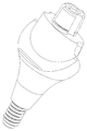
도 1은 본 발명에 따른 임플란트용 어버트먼트의 일 실시예의 사시도,
도 2는 도 1에 도시된 실시예의 평면도,
도 3은 도 1에 도시된 실시예의 정면도,
도 4는 도 1에 도시된 실시예의 몸체부재의 사시도,
도 5는 도 1에 도시된 실시예의 머리부재의 사시도,
도 6은 본 발명에 따른 임플란트용 어버트먼트의 다른 실시예의 사시도,
도 7은 도 6에 도시된 실시예의 몸체부재의 사시도,
도 8은 본 발명에 따른 임플란트용 어버트먼트의 또 다른 실시예의 사시도,
도 9는 도 8에 도시된 실시예의 몸체부재의 사시도이다.1 is a perspective view of an embodiment of an abutment for an implant according to the present invention,
2 is a plan view of the embodiment shown in FIG.
3 is a front view of the embodiment shown in FIG.
Figure 4 is a perspective view of the body member of the embodiment shown in Figure 1,
5 is a perspective view of the head member of the embodiment shown in FIG.
6 is a perspective view of another embodiment of the implant abutment according to the present invention,
Figure 7 is a perspective view of the body member of the embodiment shown in Figure 6,
8 is a perspective view of another embodiment of an implant abutment according to the present invention;
9 is a perspective view of the body member of the embodiment shown in FIG.
도 1 내지 도5를 참조하여 본 발명에 따른 임플란트용 어버트먼트의 일 실시예를 설명한다.1 to 5 an embodiment of an implant abutment according to the present invention will be described.
본 발명에 따른 임플란트용 어버트먼트의 일 실시예는 몸체부재(10)와, 머리부재(20)를 포함한다.An embodiment of the implant abutment according to the present invention includes a
몸체부재(10)는 잇몸결합부(11)와 제1보철결합부(13)를 구비한다. 잇몸결합부(11)는 픽스쳐(미도시)의 상부에 장착되어 잇몸이 결합되는 부위이다. 제1보철결합부(13)는 잇몸결합부(11)의 상부에 형성되며, 보철물이 씌워지는 부위이다. 제1보철결합부(13)에는 제1보철홈(14)과 제1그루브(18)가 형성된다. 제1보철홈(14)은 잇몸결합부(11)의 상부에서부터 하부로 형성되며, 외주면을 따라 복수 개 형성된다. 그리고 몸체부재(10)에는 중심에 축방향으로 관통된 관통구멍(15)이 형성된다. 제1그루브(18)는 보철물이 씌워진 경우 보철물의 유지력을 증가 시키며 힐링캡으로 사용이 가능하다. 이를 위하여 제1그루브(18)는 제1보철결합부(13)의 원주방향을 따라 2 내지 4개가 형성된다.
머리부재(20)는 제2보철결합부(21)와 나사부(23)를 구비한다. 제2보철결합부(21)는 제1보철결합부(13)의 상부에 장착되며, 이때 제2보철결합부(21)는 제1보철결합부(13)의 제1보철홈(14)과 간섭이 되지 않도록 형성되지 않는다. 즉 제2보철결합부(21)의 외경은 복수의 제1보철홈(14)의 내측을 서로 연결하여 형성되는 원(17)의 직경보다 크지 않아야 한다. 따라서 제2보철결합부(21)를 제1보철결합부(13)의 상부에 장착하더라도 제2보철결합부(21)가 제1보철홈(14)을 덮지 않는다.The
제2보철결합부(21)에는 제2보철홈(24)과 다각형 홈(25)과 제2그루브(26)가 형성된다. 제2보철홈(24)은 제2보철결합부(21)의 상부에서부터 하부까지 형성되며, 외주면을 따라 복수 개 형성된다. 다각형 홈(25)은 제2보철결합부(21)의 상부에 형성된다. 다각형 홈(25)은 머리부재(20)를 픽스쳐에 결합시키기 위하여 공구 등을 삽입하여 머리부재(20)를 회전시키는 데 사용된다. 나사부(23)는 몸체부재(10)의 관통구멍(25)을 관통하여 픽스쳐에 삽입될 수 있도록 제2보철결합부(21)에서 연장된다. 그리고 나사부(23)는 픽스쳐와 나사 결합을 할 수 있도록 외주면에는 나사산이 형성된다. 제2그루브(26)는 제2보철결합부(21)의 원주면을 따라 2 내지 4개 가량 형성되며, 제1그루브(18)와 마찬가지로 보철물이 씌워진 경우 보철물의 유지력을 증가시키고, 힐링캡으로 사용이 가능하다.The second
도 1에 도시된 실시예를 픽스쳐에 장착한 후 공구를 다각형 홈(25)에 삽입한 후 머리부재(20)를 회전시키면 나사부(23)가 픽스쳐와 나사결합을 하여 도 1에 도시된 실시예가 픽스쳐에 고정된다. 이때 머리부재(20)가 회전하면서 제1보철홈(14)과 제2보철홈(24)의 위치가 정확하게 일치하지 않더라도 제2보철결합부(21)가 제1보철홈(24)의 내측을 서로 연결하여 형성되는 원(17)의 직경보다 크지 않으므로 제1보철홈(14)의 상부는 모두 개방된다. 따라서 보철물을 제1보철결합부(13) 및 제2보철결합부(21)에 씌우면 보철물은 제1보철홈(14) 및 제2보철홈(24) 모두에 삽입될 수 있다. 이 경우 보철물에 힘이 가해지더라도 제1보철홈(14)에서 보철물이 삽입되어 있으므로 몸체부재(10)가 보철물을 지지한다. 따라서 머리부재(20)에 회전력이 발생하는 것을 방지하여 머리부재(20)와 픽스쳐의 나사결합이 풀리는 것을 방지할 수 있다.After mounting the embodiment shown in FIG. 1 to the fixture and inserting the tool into the
도 6 및 도 7은 본 발명에 따른 어버트먼트의 다른 실시예이다. 도 6 및 도 7을 참조하여 본 발명에 따른 어버트먼트의 다른 실시예를 설명한다.6 and 7 show another embodiment of the abutment according to the present invention. 6 and 7, another embodiment of the abutment according to the present invention will be described.
도 6에 도시된 실시예는 도 1에 도시된 실시예에 비하여 몸체부재(30)가 픽스쳐결합부(31)를 더 구비한다. 픽스쳐결합부(31)는 픽스쳐에 삽입될 수 있도록 잇몸결합부(33)의 하부에 형성된다. 이때 픽스쳐결합부(31)는 픽스쳐에 삽입된 경우 회전하지 않도록 다각형으로 형성될 수 있다. 나머지 구성요소는 도 1에 도시된 실시예와 동일하므로 자세한 설명은 생략한다.In the embodiment shown in FIG. 6, the
도 8 및 도 9는 본 발명에 따른 어버트먼트의 다른 실시예이다. 본 발명에 따른 어버트먼트는 도 8 및 도 9와 같이 실시될 수 있으며 그 구성요소는 도 1 내지 도 7과 동일하므로 자세한 설명은 생략한다.8 and 9 show another embodiment of the abutment according to the present invention. The abutment according to the present invention may be implemented as shown in FIGS. 8 and 9, and the components thereof are the same as those of FIGS. 1 to 7, and thus detailed description thereof will be omitted.
10 : 몸체부재 11 : 잇몸결합부
13 : 제1보철결합부 14 : 제1보철홈
15 : 관통구멍 17 : 원
18 : 제1그루브 20 : 머리부재
21 : 제2보철결합부 23 : 나사부
24 : 제2보철홈 25 : 다각형 홈
26 : 제2그루브 30 : 몸체부재
31 : 픽스쳐결합부 33 : 잇몸결합부10: body member 11: gum coupling portion
13: first prosthetic coupling portion 14: first prosthetic groove
15 through
18: first groove 20: head member
21: second prosthetic coupling portion 23: screw portion
24: second prosthetic groove 25: polygon groove
26: second groove 30: body member
31: fixture coupling 33: gum coupling
Claims (5)
보철물이 장착될 수 있게 상기 제1보철결합부의 상부에 위치하며 상기 제1보철홈을 덮지 않도록 형성되며 외주면에서 상부에서부터 하부까지 제2보철홈이 형성된 제2보철결합부와, 상기 몸체부재를 관통한 후 픽스쳐에 삽입되어 나사결합할 수 있도록 상기 제2보철결합부에서 연장된 나사부를 구비한 머리부재를 포함하는 것을 특징으로 하는 임플란트용 어버트먼트.A body member penetrated in the axial direction and having a gum coupling portion for coupling the gum, and a first prosthetic coupling portion formed at an upper portion of the gum coupling portion for mounting a prosthesis and having a first prosthetic groove formed from an upper side to a lower side on an outer circumferential surface thereof; ;
A second prosthetic coupling portion positioned above the first prosthetic coupling portion so as to be mounted on the first prosthetic coupling portion and not covering the first prosthetic groove, and having a second prosthetic groove formed from an outer circumferential surface thereof from the top to the bottom thereof; And a head member having a screw portion extending from the second prosthetic coupling portion to be inserted into the fixture and screwed thereafter.
상기 몸체부재는 픽스쳐에 삽입될 수 있도록 상기 잇몸결합부의 하부에 형성된 픽스쳐결합부를 더 구비하는 것을 특징으로 하는 임플란트용 어버트먼트.The method of claim 1,
The body member is an implant abutment further comprises a fixture coupling portion formed in the lower portion of the gum coupling portion to be inserted into the fixture.
상기 픽스쳐결합부는 상기 픽스쳐에 삽입된 경우 상기 픽스쳐 내에서 회전하지 않도록 다각형으로 형성된 것을 특징으로 하는 임플란트용 어버트먼트.The method of claim 2,
The fixture coupling portion is implants, characterized in that formed in a polygon so as not to rotate in the fixture when inserted into the fixture.
상기 제2보철결합부는 상부에 다각형 홈이 형성된 것을 특징으로 하는 임플란트용 어버트먼트.The method of claim 3,
The abutment for an implant, wherein the second prosthetic coupling part has a polygonal groove formed thereon.
상기 제1보철결합부는 장착된 보철물의 유지력을 증가시키기 위해서 원주방향을 따라 형성된 적어도 1개 이상의 제1그루브가 더 형성되며,
상기 제2보철결합부는 장착된 보철물의 유지력을 증가시키기 위해서 원주방향을 따라 형성된 적어도 1개 이상의 제2그루브가 더 형성된 것을 특징으로 하는 임플란트용 어버트먼트.The method according to any one of claims 1 to 4,
The first prosthetic coupling portion is further formed with at least one first groove formed along the circumferential direction to increase the holding force of the mounted prosthesis,
The second prosthetic coupling portion is an implant abutment, characterized in that at least one or more second grooves formed along the circumferential direction to increase the holding force of the mounted prosthesis.
Priority Applications (2)
| Application Number | Priority Date | Filing Date | Title |
|---|---|---|---|
| KR1020100091407A KR101028617B1 (en) | 2010-09-17 | 2010-09-17 | Implant Abutments |
| PCT/KR2011/006444 WO2012036395A2 (en) | 2010-09-17 | 2011-08-31 | Implant abutment |
Applications Claiming Priority (1)
| Application Number | Priority Date | Filing Date | Title |
|---|---|---|---|
| KR1020100091407A KR101028617B1 (en) | 2010-09-17 | 2010-09-17 | Implant Abutments |
Publications (1)
| Publication Number | Publication Date |
|---|---|
| KR101028617B1 true KR101028617B1 (en) | 2011-04-11 |
Family
ID=44049975
Family Applications (1)
| Application Number | Title | Priority Date | Filing Date |
|---|---|---|---|
| KR1020100091407A Active KR101028617B1 (en) | 2010-09-17 | 2010-09-17 | Implant Abutments |
Country Status (2)
| Country | Link |
|---|---|
| KR (1) | KR101028617B1 (en) |
| WO (1) | WO2012036395A2 (en) |
Cited By (4)
| Publication number | Priority date | Publication date | Assignee | Title |
|---|---|---|---|---|
| KR101235372B1 (en) | 2011-03-22 | 2013-02-20 | 권종진 | Implant abutment lower body |
| KR101296740B1 (en) * | 2011-10-07 | 2013-08-20 | 오스템임플란트 주식회사 | Non-submerged typed abutment for implant |
| KR20180136718A (en) * | 2017-06-15 | 2018-12-26 | 오스템임플란트 주식회사 | Healing abutment |
| KR20190082725A (en) * | 2019-07-03 | 2019-07-10 | 오스템임플란트 주식회사 | Healing abutment |
Families Citing this family (3)
| Publication number | Priority date | Publication date | Assignee | Title |
|---|---|---|---|---|
| US9877809B2 (en) * | 2012-07-23 | 2018-01-30 | Olista Ag | Abutment system for immediate implants for producing a dental prosthesis |
| KR101927465B1 (en) | 2017-06-09 | 2018-12-10 | 오스템임플란트 주식회사 | The abutment system for dental implant |
| CN112294466A (en) * | 2019-08-01 | 2021-02-02 | 詹嘉怡 | multifunctional dental implant |
Citations (4)
| Publication number | Priority date | Publication date | Assignee | Title |
|---|---|---|---|---|
| US5564921A (en) | 1990-07-05 | 1996-10-15 | Marlin; Gerald M. | Method of forming an abutment post |
| KR200345601Y1 (en) | 2003-10-30 | 2004-03-18 | 주식회사 오스템 | Abutment for repairing single tooth |
| KR200350606Y1 (en) | 2004-02-27 | 2004-05-13 | 백승관 | Rocking abertment for dental implant |
| KR20070009060A (en) * | 2005-07-15 | 2007-01-18 | 이석원 | Dental implant devices |
Family Cites Families (2)
| Publication number | Priority date | Publication date | Assignee | Title |
|---|---|---|---|---|
| KR20090002502U (en) * | 2007-09-07 | 2009-03-11 | 김정한 | Integral Abutments for Implants |
| KR101037890B1 (en) * | 2008-11-19 | 2011-05-30 | 주식회사 이노바이오써지 | Implant Abutment |
-
2010
- 2010-09-17 KR KR1020100091407A patent/KR101028617B1/en active Active
-
2011
- 2011-08-31 WO PCT/KR2011/006444 patent/WO2012036395A2/en not_active Ceased
Patent Citations (4)
| Publication number | Priority date | Publication date | Assignee | Title |
|---|---|---|---|---|
| US5564921A (en) | 1990-07-05 | 1996-10-15 | Marlin; Gerald M. | Method of forming an abutment post |
| KR200345601Y1 (en) | 2003-10-30 | 2004-03-18 | 주식회사 오스템 | Abutment for repairing single tooth |
| KR200350606Y1 (en) | 2004-02-27 | 2004-05-13 | 백승관 | Rocking abertment for dental implant |
| KR20070009060A (en) * | 2005-07-15 | 2007-01-18 | 이석원 | Dental implant devices |
Cited By (6)
| Publication number | Priority date | Publication date | Assignee | Title |
|---|---|---|---|---|
| KR101235372B1 (en) | 2011-03-22 | 2013-02-20 | 권종진 | Implant abutment lower body |
| KR101296740B1 (en) * | 2011-10-07 | 2013-08-20 | 오스템임플란트 주식회사 | Non-submerged typed abutment for implant |
| KR20180136718A (en) * | 2017-06-15 | 2018-12-26 | 오스템임플란트 주식회사 | Healing abutment |
| KR102146836B1 (en) | 2017-06-15 | 2020-08-21 | 오스템임플란트 주식회사 | Healing abutment |
| KR20190082725A (en) * | 2019-07-03 | 2019-07-10 | 오스템임플란트 주식회사 | Healing abutment |
| KR102204414B1 (en) | 2019-07-03 | 2021-01-18 | 오스템임플란트 주식회사 | Healing abutment |
Also Published As
| Publication number | Publication date |
|---|---|
| WO2012036395A2 (en) | 2012-03-22 |
| WO2012036395A3 (en) | 2012-06-07 |
Similar Documents
| Publication | Publication Date | Title |
|---|---|---|
| KR101028617B1 (en) | Implant Abutments | |
| US8333591B2 (en) | Bionic dental implant | |
| US20120178048A1 (en) | Dental implant with multiple thread patterns | |
| US9095397B2 (en) | Arrangement for insertion of implants | |
| AU2008223902B2 (en) | Dental implant, abutment structure and method for implanting a dental implant | |
| US20100304335A1 (en) | Post-extraction dental implant | |
| JP2012071139A (en) | Dental implant system | |
| SE465701B (en) | DEVICE FOR DENTAL IMPLANT INCLUDING A LOWER SCREW | |
| KR101953301B1 (en) | Dental implant assembly and dental abutment | |
| KR101331496B1 (en) | An implant device | |
| KR100997553B1 (en) | One body implant | |
| KR200386621Y1 (en) | Dental Implant | |
| US20230363865A1 (en) | Dental solid abutment | |
| KR101155702B1 (en) | One body implant | |
| JP2005270334A (en) | Dental implant | |
| JP2020054901A (en) | Dental jig | |
| US20250325352A1 (en) | Dental implant structure for preventing the upper structure of dental implants from sink-ing and preventing the ablation screw from loosening | |
| KR101134343B1 (en) | Removal driver for post screw to remove post screw | |
| KR20140003243A (en) | Dental implant | |
| KR100779227B1 (en) | Dental implant | |
| KR20140132470A (en) | Next generation implant with hybrid surface treatments | |
| CA2649804A1 (en) | Improved dental implant | |
| US20030194680A1 (en) | Dental implant fixture | |
| KR101648742B1 (en) | Abutment and the assembly of it | |
| KR200463189Y1 (en) | Implant system |
Legal Events
| Date | Code | Title | Description |
|---|---|---|---|
| A201 | Request for examination | ||
| PA0109 | Patent application |
Patent event code: PA01091R01D Comment text: Patent Application Patent event date: 20100917 |
|
| PA0201 | Request for examination | ||
| A302 | Request for accelerated examination | ||
| PA0302 | Request for accelerated examination |
Patent event date: 20100927 Patent event code: PA03022R01D Comment text: Request for Accelerated Examination Patent event date: 20100917 Patent event code: PA03021R01I Comment text: Patent Application |
|
| E902 | Notification of reason for refusal | ||
| PE0902 | Notice of grounds for rejection |
Comment text: Notification of reason for refusal Patent event date: 20101215 Patent event code: PE09021S01D |
|
| E701 | Decision to grant or registration of patent right | ||
| PE0701 | Decision of registration |
Patent event code: PE07011S01D Comment text: Decision to Grant Registration Patent event date: 20110127 |
|
| GRNT | Written decision to grant | ||
| PR0701 | Registration of establishment |
Comment text: Registration of Establishment Patent event date: 20110404 Patent event code: PR07011E01D |
|
| PR1002 | Payment of registration fee |
Payment date: 20110404 End annual number: 3 Start annual number: 1 |
|
| PG1601 | Publication of registration | ||
| FPAY | Annual fee payment |
Payment date: 20140128 Year of fee payment: 4 |
|
| PR1001 | Payment of annual fee |
Payment date: 20140128 Start annual number: 4 End annual number: 4 |
|
| FPAY | Annual fee payment |
Payment date: 20150217 Year of fee payment: 5 |
|
| PR1001 | Payment of annual fee |
Payment date: 20150217 Start annual number: 5 End annual number: 5 |
|
| FPAY | Annual fee payment |
Payment date: 20170209 Year of fee payment: 7 |
|
| PR1001 | Payment of annual fee |
Payment date: 20170209 Start annual number: 7 End annual number: 7 |
|
| FPAY | Annual fee payment |
Payment date: 20180208 Year of fee payment: 8 |
|
| PR1001 | Payment of annual fee |
Payment date: 20180208 Start annual number: 8 End annual number: 8 |
|
| FPAY | Annual fee payment |
Payment date: 20190124 Year of fee payment: 9 |
|
| PR1001 | Payment of annual fee |
Payment date: 20190124 Start annual number: 9 End annual number: 9 |
|
| PR1001 | Payment of annual fee |
Payment date: 20210329 Start annual number: 11 End annual number: 11 |
|
| PR1001 | Payment of annual fee |
Payment date: 20220411 Start annual number: 12 End annual number: 12 |
|
| PR1001 | Payment of annual fee |
Payment date: 20230502 Start annual number: 13 End annual number: 13 |
|
| PR1001 | Payment of annual fee |
Payment date: 20250120 Start annual number: 15 End annual number: 15 |