KR101020650B1 - Non-Contact Open Channel Flow Meter - Google Patents
Non-Contact Open Channel Flow Meter Download PDFInfo
- Publication number
- KR101020650B1 KR101020650B1 KR1020100074065A KR20100074065A KR101020650B1 KR 101020650 B1 KR101020650 B1 KR 101020650B1 KR 1020100074065 A KR1020100074065 A KR 1020100074065A KR 20100074065 A KR20100074065 A KR 20100074065A KR 101020650 B1 KR101020650 B1 KR 101020650B1
- Authority
- KR
- South Korea
- Prior art keywords
- flow rate
- sensor
- flow
- conduit
- open channel
- Prior art date
- Legal status (The legal status is an assumption and is not a legal conclusion. Google has not performed a legal analysis and makes no representation as to the accuracy of the status listed.)
- Expired - Fee Related
Links
Images





Classifications
-
- G—PHYSICS
- G01—MEASURING; TESTING
- G01F—MEASURING VOLUME, VOLUME FLOW, MASS FLOW OR LIQUID LEVEL; METERING BY VOLUME
- G01F1/00—Measuring the volume flow or mass flow of fluid or fluent solid material wherein the fluid passes through a meter in a continuous flow
- G01F1/704—Measuring the volume flow or mass flow of fluid or fluent solid material wherein the fluid passes through a meter in a continuous flow using marked regions or existing inhomogeneities within the fluid stream, e.g. statistically occurring variations in a fluid parameter
- G01F1/708—Measuring the time taken to traverse a fixed distance
-
- G—PHYSICS
- G01—MEASURING; TESTING
- G01B—MEASURING LENGTH, THICKNESS OR SIMILAR LINEAR DIMENSIONS; MEASURING ANGLES; MEASURING AREAS; MEASURING IRREGULARITIES OF SURFACES OR CONTOURS
- G01B21/00—Measuring arrangements or details thereof, where the measuring technique is not covered by the other groups of this subclass, unspecified or not relevant
- G01B21/16—Measuring arrangements or details thereof, where the measuring technique is not covered by the other groups of this subclass, unspecified or not relevant for measuring distance of clearance between spaced objects
-
- G—PHYSICS
- G01—MEASURING; TESTING
- G01D—MEASURING NOT SPECIALLY ADAPTED FOR A SPECIFIC VARIABLE; ARRANGEMENTS FOR MEASURING TWO OR MORE VARIABLES NOT COVERED IN A SINGLE OTHER SUBCLASS; TARIFF METERING APPARATUS; MEASURING OR TESTING NOT OTHERWISE PROVIDED FOR
- G01D21/00—Measuring or testing not otherwise provided for
- G01D21/02—Measuring two or more variables by means not covered by a single other subclass
-
- G—PHYSICS
- G01—MEASURING; TESTING
- G01F—MEASURING VOLUME, VOLUME FLOW, MASS FLOW OR LIQUID LEVEL; METERING BY VOLUME
- G01F1/00—Measuring the volume flow or mass flow of fluid or fluent solid material wherein the fluid passes through a meter in a continuous flow
- G01F1/66—Measuring the volume flow or mass flow of fluid or fluent solid material wherein the fluid passes through a meter in a continuous flow by measuring frequency, phase shift or propagation time of electromagnetic or other waves, e.g. using ultrasonic flowmeters
-
- G—PHYSICS
- G01—MEASURING; TESTING
- G01P—MEASURING LINEAR OR ANGULAR SPEED, ACCELERATION, DECELERATION, OR SHOCK; INDICATING PRESENCE, ABSENCE, OR DIRECTION, OF MOVEMENT
- G01P5/00—Measuring speed of fluids, e.g. of air stream; Measuring speed of bodies relative to fluids, e.g. of ship, of aircraft
- G01P5/08—Measuring speed of fluids, e.g. of air stream; Measuring speed of bodies relative to fluids, e.g. of ship, of aircraft by measuring variation of an electric variable directly affected by the flow, e.g. by using dynamo-electric effect
-
- G—PHYSICS
- G01—MEASURING; TESTING
- G01P—MEASURING LINEAR OR ANGULAR SPEED, ACCELERATION, DECELERATION, OR SHOCK; INDICATING PRESENCE, ABSENCE, OR DIRECTION, OF MOVEMENT
- G01P5/00—Measuring speed of fluids, e.g. of air stream; Measuring speed of bodies relative to fluids, e.g. of ship, of aircraft
- G01P5/18—Measuring speed of fluids, e.g. of air stream; Measuring speed of bodies relative to fluids, e.g. of ship, of aircraft by measuring the time taken to traverse a fixed distance
-
- G—PHYSICS
- G01—MEASURING; TESTING
- G01S—RADIO DIRECTION-FINDING; RADIO NAVIGATION; DETERMINING DISTANCE OR VELOCITY BY USE OF RADIO WAVES; LOCATING OR PRESENCE-DETECTING BY USE OF THE REFLECTION OR RERADIATION OF RADIO WAVES; ANALOGOUS ARRANGEMENTS USING OTHER WAVES
- G01S13/00—Systems using the reflection or reradiation of radio waves, e.g. radar systems; Analogous systems using reflection or reradiation of waves whose nature or wavelength is irrelevant or unspecified
- G01S13/02—Systems using reflection of radio waves, e.g. primary radar systems; Analogous systems
- G01S13/06—Systems determining position data of a target
- G01S13/08—Systems for measuring distance only
Landscapes
- Physics & Mathematics (AREA)
- General Physics & Mathematics (AREA)
- Engineering & Computer Science (AREA)
- Radar, Positioning & Navigation (AREA)
- Remote Sensing (AREA)
- Fluid Mechanics (AREA)
- Aviation & Aerospace Engineering (AREA)
- Measuring Volume Flow (AREA)
- Electromagnetism (AREA)
- Computer Networks & Wireless Communication (AREA)
Abstract
본 발명은 부유물이 쌓이지 않으면서 유속 측정이 정확하고 유지 비용이 저렴한 비접액식 오픈 채널 유량계를 제공하는데 목적이 있다.
이 목적을 달성하기 위한 수단으로서, 본 발명에 따른 비접액식 오픈 채널 유량계는 관로(300) 내를 흐르는 유체의 표면으로부터 연직 방향으로 이격되어 설치되고, 초음파 거리 센서(754) 및 마이크로파 레이더 센서(758)가 하나의 하우징 내에 형성된 유량 센서부(200); 및 상기 유량 센서부(200)와 전기적으로 연결된 유량 연산 유닛(100)을 포함하는 비접액식 오픈 채널 유량계로서, 상기 초음파 거리 센서(754)는 초음파를 이용하여 상기 관로(300) 내를 흐르는 유체의 표면으로부터 상기 유량 센서부(200)까지의 거리를 측정하고, 상기 마이크로파 레이더 센서(758)는 마이크로파를 이용하여 상기 관로(300) 내를 흐르는 유체의 표면 유속을 측정하고, 상기 유량 연산 유닛(100)은 상기 거리 및 상기 표면 유속을 상기 유량 센서부(200)로부터 전송받아서, 상기 거리에 의거하여 상기 관로(300) 내를 흐르는 유체의 단면적을 구하고, 상기 단면적에 상기 표면 유속을 승산하여 유량을 산출하는 것을 특징으로 한다.It is an object of the present invention to provide a non-contact open channel flow meter that is accurate in flow rate measurement and low in maintenance costs without accumulating suspended matter.
As a means for achieving this object, the non-contact open channel flow meter according to the present invention is installed spaced apart in the vertical direction from the surface of the fluid flowing in the conduit 300, ultrasonic distance sensor 754 and microwave radar sensor 758 A flow sensor part 200 formed in one housing; And a flow rate calculation unit 100 electrically connected to the flow rate sensor unit 200, wherein the ultrasonic distance sensor 754 is configured to control the flow of fluid flowing in the conduit 300 using ultrasonic waves. The distance from the surface to the flow sensor unit 200 is measured, and the microwave radar sensor 758 measures the surface flow velocity of the fluid flowing in the conduit 300 by using the microwave, and the flow rate calculation unit 100 ) Receives the distance and the surface flow rate from the flow sensor unit 200, obtains the cross-sectional area of the fluid flowing in the conduit 300 based on the distance, multiplies the cross-sectional area by the surface flow rate to increase the flow rate. It is characterized by calculating.
Description
본 발명은 순시 유량을 측정하여 유량을 산출하는 비접액식 오픈 채널 유량계에 관한 것으로, 특히 마이크로파 레이더 센서를 구비하여 유량을 산출하는 비접액식 오픈 채널 유량계에 관한 것이다.The present invention relates to a non-contact open channel flow meter for measuring instantaneous flow rate and to calculate a flow rate, and more particularly to a non-contact open channel flow meter having a microwave radar sensor for calculating a flow rate.
근래, 폐수처리 시스템 또는 하천 등의 오픈 채널 유량의 정밀 측정은 폐수 처리 시스템 또는 재해예방에 대한 관심도가 높아지면서 날로 중요해지고 있다. 이러한 시설물에서 순간 최고 유량의 흐름에 의한 피해를 막기 위해서 실제 흐르는 유량을 매우 정밀하고 안정적으로 측정할 필요가 있다.In recent years, the precise measurement of the flow rate of open channels, such as wastewater treatment systems or rivers, has become increasingly important with increasing interest in wastewater treatment systems or disaster prevention. In order to prevent damage by instantaneous peak flow in these facilities, it is necessary to measure the actual flow rate very precisely and reliably.
이러한 필요성에 따라 오픈 채널 유량계가 다수 개발되고 있다. 종래의 오픈 채널 유량계에 의해서 유량을 산출하는 하나의 예를 도 1 및 도 2를 참조하여 설명한다. 여기에서 오픈 채널이란 맨홀 등을 구비한 상수관 또는 관로, 하천 등과 같이 관이 차폐되어 있지 않고 오픈되어 있는 상태를 나타낸다.Many open channel flowmeters have been developed for this need. One example of calculating the flow rate using a conventional open channel flow meter will be described with reference to FIGS. 1 and 2. In this case, the open channel refers to a state in which a pipe is not shielded and is open, such as a water pipe having a manhole, a pipe, a river, or the like.
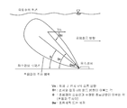
도 1은 종래의 초음파 수위 센서와 초음파 유속센서를 구비한 접액식 오픈 채널 유량계를 개략적으로 나타낸 설명도이고, 도 2는 도 1의 초음파 유속 센서에 있어서 초음파의 조사 범위를 나타낸 설명도이다.1 is an explanatory diagram schematically showing a liquid-contact open channel flowmeter having a conventional ultrasonic water level sensor and an ultrasonic flow rate sensor, and FIG. 2 is an explanatory diagram showing an irradiation range of ultrasonic waves in the ultrasonic flow rate sensor of FIG. 1.
도 1의 접액식 오픈 채널 유량계는 초음파 수위 센서(10), 초음파 유속 센서(20), 및 승산기(40)를 포함한다. 초음파 수위 센서(10)는 관로(30)의 오픈된 맨홀의 상단에 설치되고, 초음파 유속 센서(20)는 관로(30)의 바닥면에 설치된다. 접액식 유량계에서, 초음파 수위 센서(10)는 관로(300) 또는 하천 등 개수로 공간에 흐르는 유체의 수위를 측정하고 그 결과를 승산기(40)에 입력하고, 초음파 유속 센서(20)는 관로 내를 흐르는 유체의 유속을 측정하고 그 결과를 승산기(40)에 입력한다. 승산기(40)는 초음파 수위 센서(10)로부터 입력된 수위에 근거하여 관로에 흐르는 유체의 단면적을 산출하고, 이 산출된 유체의 단면적에, 초음파 유속 센서(20)로부터 입력된 유속을 승산하여 얻어진 유량을 출력한다.The wetted open channel flow meter of FIG. 1 includes an ultrasonic
도 1에서, 초음파 수위 센서(10)는 초음파를 송신하고 나서 수신할 때까지의 시간을 측정하여 수위를 산출하고, 초음파 유속 센서(20)는 초음파가 유체의 흐름 속의 미소입자에 의해서 산란할 때 도플러효과에 의해 주파수가 변화하는데 그 주파수 변화가 입자속도에 비례하는 것을 이용해서 유속을 측정한다.In FIG. 1, the ultrasonic
이러한 초음파 유속 센서(20)는 관로의 바닥에 장착되어 있고, 유체에 항상 잠겨 있는 상태에서 초음파를 방사한다. 초음파 유속 센서(20)로부터 방사된 초음파의 조사 범위는 도 2에 도시된 바와 같이 콘(Cone)모양이며, 콘 모양의 조사 범위 내에는 수많은 입자가 존재한다. 따라서, 초음파의 조사 범위 내에 넓게 퍼져 있는 각종 입자 n에 대하여 각각 도플러 효과가 발생하기 때문에, 초음파 유속 센서(20)는 어느 입자를 기준으로 하여 속도를 측정하느냐에 따라 유속이 달라지고 그 편차도 커진다. 즉, 도 2에서 θ각을 이루는 곳에 있는 입자 n과 θn각을 이루는 곳에 있는 입자 n은 각각 다른 속도로 이동하고 θw각이 클수록 속도 차이가 더 심해지는 것을 알 수 있다. 여기서, Vn은 유체 내 입자 n의 흐름 방향이고, θn은 초음파 유속 센서(20)와 입자 n의 운동 방향이 이루는 각이고, θ는 초음파의 중심선과 추정된 흐름 방향이 이루는 각(초음파 투사각)이고, θw는 초음파폭 또는 퍼짐을 나타낸다. The ultrasonic
즉, 초음파 유속 센서(20)로부터 방사된 초음파의 조사 범위 내에는 수많은 입자가 존재하며 초음파가 미치는 영역의 여러 부분에서 유체 유동프로파일(Profile)에 따라 각각 다른 속도로 이동하고 있어서 실제 유속을 측정하더라도 오차가 심하고, 다수 입자로 인해 노이즈 발생률이 높고 불연속적인 도플러 신호가 발생하는 단점이 있다.That is, even though a large number of particles exist within the irradiation range of the ultrasonic wave radiated from the ultrasonic
또한, 도 2의 초음파 유속 센서(20)는 관로의 바닥에 장착되기 때문에 장시간 경과되면 퇴적물이 초음파 유속 센서(20)의 본체에 쌓이게 되어 측정 오차가 점점 커지고, 유지 보수가 어렵고, 이에 수반하여 주기적인 청소가 필요하기 때문에 유지 비용이 상승하는 문제점이 있다. In addition, since the ultrasonic
따라서, 본 발명은 상술한 종래의 접액식 오픈 채널 유량계의 문제점을 감안하여 이루어진 것으로, 본체에 부유물이 쌓이지 않으면서 유속 측정이 정확하고 유지 비용이 저렴한 비접액식 오픈 채널 유량계를 제공하는데 목적이 있다.Accordingly, the present invention has been made in view of the above-described problems of the conventional liquid open channel flow meter, and an object thereof is to provide a non-contact open channel flow meter which is accurate in measuring flow velocity and low in maintenance cost without accumulating suspended matter in the main body.
상기 목적을 달성하기 위해서, 본 발명의 제 1 실시예에 따른 비접액식 오픈 채널 유량계는, 관로 내를 흐르는 유체의 표면으로부터 연직 방향으로 이격되어 설치되고, 초음파 거리 센서 및 마이크로파 레이더 센서가 하나의 하우징 내에 형성된 유량 센서부; 및 상기 유량 센서부와 전기적으로 연결된 유량 연산 유닛을 포함하는 비접액식 오픈 채널 유량계로서, 상기 초음파 거리 센서는 초음파를 이용하여 상기 관로 내를 흐르는 유체의 표면으로부터 상기 유량 센서부까지의 거리를 측정하고, 상기 마이크로파 레이더 센서는 마이크로파를 이용하여 상기 관로 내를 흐르는 유체의 표면 유속을 측정하고, 상기 유량 연산 유닛은 상기 거리 및 상기 표면 유속을 상기 유량 센서부로부터 전송받아서, 상기 거리에 의거하여 상기 관로 내를 흐르는 유체의 단면적을 구하고, 상기 단면적에 상기 표면 유속을 승산하여 유량을 산출하는 것을 특징으로 한다.In order to achieve the above object, the non-contact open channel flow meter according to the first embodiment of the present invention is installed spaced apart in the vertical direction from the surface of the fluid flowing in the pipeline, the ultrasonic distance sensor and the microwave radar sensor is one housing A flow sensor unit formed therein; And a flow rate calculation unit electrically connected to the flow rate sensor unit, wherein the ultrasonic distance sensor measures the distance from the surface of the fluid flowing in the conduit to the flow rate sensor unit using ultrasonic waves. The microwave radar sensor measures the surface flow velocity of the fluid flowing in the conduit using microwaves, and the flow rate calculation unit receives the distance and the surface flow velocity from the flow sensor unit, based on the distance. The cross-sectional area of the fluid flowing inside is calculated, and the flow rate is calculated by multiplying the cross-sectional area by the surface flow rate.
본 발명의 제 2 실시예에 따른 비접액식 오픈 채널 유량계는, 본 발명의 제 2 실시예에 따른 비접액식 오픈 채널 유량계에 있어서, 상기 관로 내를 흐르는 유체의 표면으로부터 연직 방향으로 이격되는 동시에 상기 유량 센서부에 비하여 유체 흐름의 상류 측에 설치되어, 상기 유체의 표면에 파고를 발생시키는 파고 발생장치를 더 포함하는 것을 특징으로 한다.A non-contact open channel flow meter according to a second embodiment of the present invention is a non-contact open channel flow meter according to a second embodiment of the present invention, wherein the flow rate is vertically spaced apart from the surface of the fluid flowing in the conduit. It is characterized in that it further comprises a crest generating device is installed on the upstream side of the fluid flow compared to the sensor portion, and generates crests on the surface of the fluid.
본 발명의 제 3 실시예에 따른 비접액식 오픈 채널 유량계는, 본 발명의 제 1 또는 제 2 실시예에 따른 비접액식 오픈 채널 유량계에 있어서, 상기 관내를 흐르는 유체의 표면으로부터 연직 방향으로 이격되는 동시에 상기 유량 센서부에 비하여 유체 흐름의 상류 측에 설치되어, 상기 유체의 표면을 촬상함으로써 이미지 데이터를 생성하는 촬상 장치를 더 포함하고, 상기 촬상 장치는 상기 이미지 데이터를 전기적으로 연결된 상기 유량 연산 유닛에 전송하고, 상기 유량 연산 유닛은 상기 이미지 데이터로부터 특징점을 추출하고, 디지털 신호 처리에 의해서 상기 특징점의 이동 벡터를 검출하고, 검출된 이동 벡터에 근거하여 특징점 이동 속도를 산출하고, 상기 특징점 이동 속도와 상기 마이크로파 레이더 센서로부터 측정된 상기 표면 유속과의 차만큼 상기 유량을 보정하는 것을 특징으로 한다.The non-contact open channel flow meter according to the third embodiment of the present invention is a non-contact open channel flow meter according to the first or second embodiment of the present invention, wherein the non-contact open channel flow meter is spaced apart from the surface of the fluid flowing in the pipe in a vertical direction. An image pickup device installed on an upstream side of the fluid flow relative to the flow rate sensor portion, the image pickup device generating image data by imaging the surface of the fluid, wherein the image pickup device is connected to the flow rate calculation unit electrically connected to the image data. And the flow rate calculating unit extracts a feature point from the image data, detects a motion vector of the feature point by digital signal processing, calculates a feature point movement speed based on the detected motion vector, By the difference from the surface flow velocity measured from the microwave radar sensor It is characterized in that for correcting the flow rate.
본 발명의 제 3 실시예에 따른 비접액식 오픈 채널 유량계에 있어서, 상기 특징점은 상기 촬상 장치에 의해서 촬상된 상기 이미지 데이터 중에서 상기 관로내를 흐르는 유체의 표면에 떠있는 거품이나 부유물의 위치데이터를 나타내는 것을 특징으로 한다.In the non-contact open channel flow meter according to the third embodiment of the present invention, the feature point indicates position data of bubbles or floats floating on the surface of the fluid flowing in the conduit among the image data captured by the imaging device. It is characterized by.
본 발명의 제 4 실시예에 따른 비접액식 오픈 채널 유량계는, 본 발명의 제 1 또는 제 2 실시예에 따른 비접액식 오픈 채널 유량계에 있어서, 상기 관로 내에 흐르는 유체에 삽입되어 유속을 측정하는 바형상의 측정 포인터를 구비한 멀티 포인트 유량계(multi-point flowmeter)를 더 포함하고, 상기 멀티 포인트 유량계는 상기 바형상의 측정 포인터에 의해서 측정된 유속과 상기 마이크로파 레이더 센서로부터 측정된 상기 표면 유속과의 차만큼 상기 유량을 보정하는 것을 특징으로 한다.A non-contact open channel flow meter according to a fourth embodiment of the present invention is a non-contact open channel flow meter according to a first or second embodiment of the present invention, wherein a bar shape is inserted into a fluid flowing in the pipeline to measure a flow rate. And a multi-point flowmeter having a measuring pointer of the multipoint flowmeter, wherein the multi-point flowmeter has a difference between the flow rate measured by the bar-shaped measuring pointer and the surface flow rate measured from the microwave radar sensor. As described above, the flow rate is corrected.
본 발명에 의하면, 센서가 관로 바닦에 설치되지 않아서 부유물이 쌓이지 않으며 유속 측정이 정확하고 유지 비용이 저렴한 비접액식 오픈 채널 유량계를 제공할 수 있다.According to the present invention, it is possible to provide a non-contact open channel flowmeter because the sensor is not installed at the bottom of the pipe so that suspended matter does not accumulate, the flow rate measurement is accurate, and the maintenance cost is low.
도 1은 종래의 초음파 센서와 초음파 유속 센서를 구비한 접액식 오픈 채널 유량계를 개략적으로 나타낸 설명도이다.
도 2는 도 1의 초음파 유속 센서에 있어서 초음파의 조사 범위를 나타낸 설명도이다.
도 3은 본 발명의 제 1 실시예에 따른 비접액식 오픈 채널 유량계가 설치된 상태를 나타낸 도면이다.
도 4는 도 3의 비접액식 오픈 채널 유량계의 내부 구성을 기능별로 나타낸 블록도이다.
도 5는 본 발명의 제 2 실시예에 따른 비접액식 오픈 채널 유량계가 설치된 상태를 나타낸 도면이다.
도 6은 도 5의 비접액식 오픈 채널 유량계의 내부 구성을 기능별로 나타낸 블록도이다.
도 7은 본 발명의 제 3 실시예에 따른 비접액식 오픈 채널 유량계가 설치된 상태를 나타낸 도면이다.
도 8은 도 7의 비접액식 오픈 채널 유량계의 내부 구성을 기능별로 나타낸 블록도이다.
도 9는 도 7의 제 3 실시예에 따른 비접액식 오픈 채널 유량계에 있어서 유속을 측정하는 원리는 나타낸 개념도이다.
도 10은 본 발명의 4 실시예에 따른 비접액식 오픈 채널 유량계의 내부 구성을 기능별로 나타낸 블록도이다.1 is an explanatory view schematically showing a liquid-contact open channel flow meter having a conventional ultrasonic sensor and ultrasonic flow rate sensor.
It is explanatory drawing which showed the irradiation range of the ultrasonic wave in the ultrasonic flow velocity sensor of FIG.
3 is a view showing a state in which a non-contact open channel flow meter according to a first embodiment of the present invention is installed.
4 is a block diagram illustrating the internal configuration of the non-contact open channel flow meter of FIG.
5 is a view showing a state in which a non-contact open channel flow meter according to a second embodiment of the present invention is installed.
FIG. 6 is a block diagram illustrating the internal configuration of the non-contact open channel flow meter of FIG.
7 is a view showing a state in which a non-contact open channel flow meter according to a third embodiment of the present invention is installed.
FIG. 8 is a block diagram illustrating the internal configuration of the non-contact open channel flow meter of FIG.
9 is a conceptual diagram illustrating a principle of measuring a flow rate in a non-contact open channel flow meter according to a third embodiment of FIG. 7.
10 is a block diagram showing the internal configuration of a non-contact open channel flow meter according to a fourth embodiment of the present invention by function.
이하, 본 발명에 따른 비접액식 오픈 채널 유량계를 첨부된 도면을 참조하여 설명한다. 본 발명에서는 표면 유속을 측정하기 위해서 초음파 유속 센서 대신에 마이크로파 레이더 센서를 채용하고 있다.Hereinafter, a non-contact open channel flow meter according to the present invention will be described with reference to the accompanying drawings. In the present invention, in order to measure the surface flow rate, a microwave radar sensor is used instead of the ultrasonic flow rate sensor.
먼저, 본 발명의 제 1 실시예에 따른 비접액식 오픈 채널 유량계를 도 3 및 도 4를 참조하여 설명한다. 이하 설명에서 언급되는 거리, 표면 유속 및 유량은 아날로그 값 또는 디지털 값과 같은 물리량으로 표현할 수 있는 전기 신호로서 일종의 데이터 정보이다. 따라서, 거리, 표면 유속 및 유량은 각각 거리값, 표면 유속값 및 유량값, 또는 거리 신호, 표면 유속 신호 및 유량 신호, 또는 거리 데이터, 표면 유속 데이터 및 유량 데이터와 같이 구체적으로 표시하지 않더라도(필요에 따라 구체적으로 표현된 곳도 있음), 당해 분야에 숙련된 자에 의해서 필요에 따라 얻을 수 있는 임의의 물리량을 의미하는 것으로 한다.
First, a non-contact open channel flow meter according to a first embodiment of the present invention will be described with reference to FIGS. 3 and 4. The distances, surface flow rates, and flow rates mentioned in the following description are electrical signals that can be expressed as physical quantities such as analog values or digital values, which are a kind of data information. Thus, distance, surface flow rate and flow rate are not specifically indicated, such as distance value, surface flow rate value and flow rate value, or distance signal, surface flow rate signal and flow rate signal, or distance data, surface flow rate data and flow rate data, respectively (required It may mean a certain physical quantity that can be obtained as needed by those skilled in the art.
제 1 실시예First embodiment
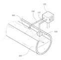
도 3은 본 발명의 제 1 실시예에 따른 비접액식 오픈 채널 유량계가 설치된 상태를 나타낸 도면이고, 도 4는 도 3의 비접액식 오픈 채널 유량계의 내부 구성을 기능별로 나타낸 블록도이다.3 is a view showing a state in which a non-contact open channel flow meter is installed according to a first embodiment of the present invention, Figure 4 is a block diagram showing the internal configuration of the non-contact open channel flow meter of Figure 3 by function.
도 3에서, 본 발명의 제 1 실시예에 따른 비접액식 오픈 채널 유량계는 유량 연산 유닛(100)과 유량 센서부(200)를 포함하고, 유량 연산 유닛(100)과 유량 센서부(200)는 유량 센서 케이블(110)에 의해서 서로 전기적으로 연결되어 있다. 유량 센서부(200)는 예를 들면 관로(300) 또는 하천 등 개수로 공간에 흐르는 유체 표면에 대하여 연직 상방에 설치되어 유체의 표면에서 유량 센서부(200)까지의 거리과 유체의 표면 유속을 동시에 검출하고, 검출된 거리와 표면 유속을 유량 센서 케이블(110)을 통해서 유량 연산 유닛(100)에 전송한다. 유량 연산 유닛(100)은 전송된 거리에 의해서 관로(300) 내를 흐르는 유체의 단면적을 구하고, 이 유체의 단면적에 표면 유속을 승산하여 유량을 산출하고, 산출된 유량을 표시부(700)에 표시하고 출력부(720)를 통해서 출력한다.In FIG. 3, the non-contact open channel flowmeter according to the first embodiment of the present invention includes a flow
도 3에 도시된 바와 같이, 관로(300)는 제조 당시부터 단면적이 정해져 있기 때문에, 유량 센서부(200)는, 유체 표면으로부터의 거리만 알면, 유체의 수위와 유체의 단면적을 산출할 수 있다. 상술한 거리와 표면 유속에 의해서 유량을 산출하는 방법은 특별히 한정되지 않으며 당해 분야에서 숙련된 자에 의해서 취사선택할 수 있는 어떤 것이어도 좋다.As shown in FIG. 3, since the cross-sectional area of the
유량 센서부(200)는 도 4에 도시된 바와 같이 초음파 거리 센서(754)와 마이크로파 레이더 센서(758)를 구비하고 있다. 도 3에 도시된 바와 같이 초음파 거리 센서(754)와 마이크로파 레이더 센서(758)는 하나의 하우징 내에 일체로 설치되어 있다.As illustrated in FIG. 4, the
초음파 거리 센서(754)는 관로(300) 내를 흐르는 유체의 표면을 향해 도 3에 도시된 바와 같이 연직 하방으로 초음파를 송신하고 유체의 표면에 의해서 반사되어 오는 초음파를 수신한다. 이때 사용되는 초음파의 주파수 범위는 특별히 한정되지 않고 당해 분야에서 숙련된 자에 의해서 정밀도에 따라 취사선택할 수 있다.The
마이크로파 레이더 센서(758)는 관로(300) 내를 흐르는 유체의 표면에 대하여 30ㅀ내지 50ㅀ의 입사각으로 마이크로파를 송신하고 유체의 표면에서 산란되어 돌아오는 마이크로파를 수신한다. 이때 입사각은 유체의 표면에 대하여 연직 하방을 90ㅀ로 정의한 경우이다. 도 1 및 도 2에 도시된 초음파 유속 센서(20)는 초음파를 사용하지만, 본 실시예에서 사용되는 마이크로파 레이더 센서(754)는 마이크로파를 사용하며, 주파수 범위는 대략 15GHz 내지 30GHz 범위 내에서 사용되고 있으며, 바람직하게는 대략 23GHz 내지 25GHz 범위 내의 주파수가 사용되고 있다.The
본 발명에서 사용되는 초음파 거리 센서(754)와 마이크로파 레이더 센서(758)의 구체적인 구성은 상술한 거리와 표면 유속을 측정할 수 있기만 하면 특별히 한정되지 않고 상업적으로 입수할 수 있는 어떠한 것이어도 좋다. 이 경우, 당해 분야에서 숙련된 자는 표면 유속을 얼마나 정밀하게 측정할 수 있는지에 대한 분해능을 고려할 수 있다. 분해능은, 분해능 = 전파속도 ㅧ 펄스폭 / 2에 의해서 구해지므로, 폴스폭이 작으면 작을수록(주파수가 높을수록) 분해능이 우수하다는 것을 알 수 있다.The specific configuration of the
도 4에서, 유량 연산 유닛(100)은 표시부(700), 제어부(710), 출력부(720), 기억부(730), 키패드(740), 연산처리부(750), 거리 산출부(752), 및 유속 산출부(756)를 포함한다.In FIG. 4, the flow
제어부(710)는 표시부(700), 출력부(720), 기억부(730), 키패드(740), 연산처리부(750), 거리 산출부(752), 및 유속 산출부(756)와 전기적으로 연결되어 각각을 직간접적으로 제어한다.The
기억부(730)는 유량 연산 유닛(100)을 기동하는 OS(operating system) 프로그램 및 유량이 저장된다. 제어부(710)는 유량 연산 유닛(100)에 전원이 인가되면 기억부(730)에 저장된 OS 프로그램을 판독하여 표시부(700), 출력부(720), 기억부(730), 키패드(740), 연산처리부(750), 거리 산출부(752), 및 유속 산출부(756)를 초기화하도록 제어한다.The
키패드(740)는 사용자가 유량 연산 유닛(100)에 조건 또는 조작 명령과 같은 각종 입력을 행할 수 있는 장치이다. 표시부(700)는 유량이 표시되고, 유량 연산 유닛(100)의 작동 상태가 표시되고, 사용자가 키패드를 통해 조건 또는 조작 명령을 입력할 수 있도록 메뉴가 표시된다. 출력부(720)는 외부 장치(도시 생략) 또는 인터넷망(도시 생략)에 연결되어 유량을 전기 신호로서 출력한다.The
거리 산출부(752)는 유량 센서(200)의 초음파 거리 센서(754)에 전기적으로 연결되어 유량 센서(200)의 초음파 거리 센서(754)를 제어한다. 거리 산출부(752)는 초음파 거리 센서(754)에게 초음파를 송수신하도록 지령을 내리고 초음파가 송신된 후 반사되어 돌아올 때까지의 시간을 카운팅하고, 카운팅된 시간에 상기 초음파의 전파 속도를 승산하여 거리를 산출한다. 이러한 거리 산출 방법은 이에 한정되지 않으며 당해 분야에서 숙련된 자에 의해서 필요에 따라 취사 선택할 수 있는 어떠한 방법이어도 좋다. 이렇게 산출된 거리는 연산 처리부(750)로 전송된다.The
유속 산출부(756)는 유량 센서(200)의 마이크로파 레이더 센서(758)에 전기적으로 연결되어 유량 센서(200)의 마이크로파 레이더 센서(758)를 제어한다. 유속 산출부(756)는 마이크로파 레이더 센서(758)에게 마이크로파를 송수신하도록 지령을 내리고, 도플러 효과에 의한 표면 유속을 산출한다. 도플러 효과에 의한 표면 유속 산출 방법은 당해 분야에서 숙련된 자에게 명백히 알 수 있으므로 구체적인 설명은 생략한다. 이렇게 산출된 표면 유속은 연산 처리부(750)로 전송된다.The
연산 처리부(750)는 전송된 거리에 근거하여 관로(300) 내에 흐르는 유체의 단면적을 산출하고, 산출된 단면적에 상기 전송된 표면 유속을 승산하여 유량을 산출하고 이를 제어부(710)에 전송한다. 이때, 제어부(710)는 전송된 유량을 표시부(700)에 표시하는 동시에 기억부(730)에 저장하고, 또한 출력부(720)에 전송한다. 이 유량은 시간정보에 매칭하여 기억부(730)에 저장될 수 있다. 시간 정보에 매칭되어 저장된 유량은 사용자가 키패드(740)에 의한 조작에 의해 언제든지 기억부(730)로부터 판독하여 표시부(700)에 표시될 수 있다.The
이상 설명한 바와 같이, 본 발명의 제 1 실시예에 따른 비접액식 오픈 채널 유량계는, 유량 센서부(200)의 초음파 거리 센서(754)와 마이크로파 레이더 센서(758)와, 유량 연산 유닛(100)의 거리 산출부(752), 유속 산출부(756) 및 연산 처리부(750)에 의해서, 관로(300) 내를 흐르는 유체의 유량을 산출하고, 이를 표시부(700)에 표시하는 동시에, 시간 정보에 매칭시켜 기억부(730)에 저장하고, 또한 전기 신호로서 출력부(720)를 통해 외부 장치 또는 인터넷 망에 출력한다.As described above, the non-contact open channel flowmeter according to the first embodiment of the present invention includes the
본 발명의 제 1 실시예에 따른 비접액식 오픈 채널 유량계에 의하면, 관로(300) 내를 흐르는 액체와 접하지 않기 때문에 유량계에 부유물이 쌓이지 않고, 또한 마이크로파 레이더 센서(758)는 기존의 초음파 유속 센서(20)와 달리 마이크로파 를 사용하기 때문에 분해능이 우수하여, 유체 내에 넓게 퍼져 있는 입자에 의해서 의도하지 않게 발생되는 도플러 효과에 의한 잡음을 억제할 수 있고 이에 수반하여 정밀도를 향상시킬 수 있는 효과가 있다.
According to the non-contact open channel flow meter according to the first embodiment of the present invention, since the liquid does not come into contact with the liquid flowing in the
다음으로, 본 발명의 제 2 실시예에 따른 비접액식 오픈 채널 유량계를 도 5 및 도 6을 참조하여 설명한다.
Next, a non-contact open channel flow meter according to a second embodiment of the present invention will be described with reference to FIGS. 5 and 6.
제 2 실시예Second embodiment
본 발명의 제 1 실시예에 따른 비접액식 오픈 채널 유량계에 있어서, 관로(300) 내를 흐르는 유체의 표면 속도가 매우 느리거나 유체 내에 불순물이 거의 포함되어 있지 않은 경우, 마이크로파 레이더 센서(758)에 의해서 송신된 레이더가 유체의 표면에서 산란되지 않아 측정이 이루어지지 않는 경우가 발생한다. 즉, 도 3에 도시된 바와 같이 유량 센서부(200)에서는 초음파가 유체의 표면의 연직 하방을 향해서 방사되고, 레이더가 유체의 표면에 대하여 비스듬하게 경사져서 방사된다. 이렇게 경사져 방사된 레이더는 유체의 표면에서 산란되지 않게 되면 유량 센서부(200)로 되돌아 오지 않게 되어, 종종 측정이 이루어지지 않는 문제가 있다.In the non-contact open channel flow meter according to the first embodiment of the present invention, when the surface velocity of the fluid flowing in the
따라서, 본 발명의 제 2 실시예에 따른 비접액식 오픈 채널 유량계는 이러한 문제를 감안하여 이루어진 것이다.Therefore, the non-contact open channel flowmeter according to the second embodiment of the present invention has been made in view of such a problem.
본 발명의 제 2 실시예에 따른 비접액식 오픈 채널 유량계를 도 5 및 도 6을 참조하여 설명한다.A non-contact open channel flow meter according to a second embodiment of the present invention will be described with reference to FIGS. 5 and 6.
도 5는 본 발명의 제 2 실시예에 따른 비접액식 오픈 채널 유량계가 설치된 상태를 나타낸 도면이고, 도 6은 도 5의 비접액식 오픈 채널 유량계의 내부 구성을 기능별로 나타낸 블록도이다.5 is a view showing a state in which a non-contact open channel flow meter according to a second embodiment of the present invention is installed, Figure 6 is a block diagram showing the internal configuration of the non-contact open channel flow meter of FIG.
도 5 및 도 6은 상술한 도 3 및 도 4에 비교하여 파고 발생장치(400)가 더 포함되어 있는 것을 제외하고는 그 구성이 동일하기 때문에, 동일한 도면 번호를 부여하고 그에 대한 설명은 생략한다.5 and 6 have the same reference numerals, and the description thereof will be omitted since the configuration is the same except that the wave
앞서 설명한 바와 같이, 관로(300) 내를 흐르는 유체의 표면 속도가 매우 느리거나 유체 내에 불순물이 거의 포함되어 있지 않은 경우에는 마이크로파 레이더 센서(758)에 의한 유체의 표면 유속이 측정되지 않기 때문에, 임의로 유체의 표면에 잔물결인 파고를 형성해줄 필요가 있다.As described above, if the surface velocity of the fluid flowing in the
이를 달성하기 위해서, 본 발명의 제 2 실시예에 따른 비접액식 오픈 채널 유량계는 파고 발생장치(400)가 더 구비되어 있다. 파고 발생 장치(400)는 유량 센서부(200)보다 유체 흐름의 상류측에 마련된다. 파고 발생 장치(400)는 유량 연산 유닛(100)의 제어부(710)에 의해서 제어된다. 파고 발생 장치(400)와 유량 연산 유닛(100)의 제어부(710)는 파고 발생 장치 케이블(110)에 의해서 서로 전기적으로 연결되어 있다.In order to achieve this, the non-contact open channel flow meter according to the second embodiment of the present invention is further provided with a
유량 연산 유닛(100)의 제어부(710)는 연산 처리부(750)로부터 유량이 전송되어 오지 않으면, 관로(300) 내를 흐르는 유속이 매우 느리거나 유체 내에 불순물이 거의 포함되어 있지 않다고 판단하여 파고 발생 장치(400)를 작동시킨다.If the flow rate is not transmitted from the
도 5에는 파고 발생 장치(400)의 구체적인 구성에 대하여 도시되어 있지 않지만, 파고 발생 장치(400)는 압축 공기를 유체의 표면을 향하여 발사하도록 구성되어 있다. Although not shown in FIG. 5 for the specific configuration of the
본 실시예에서 파고 발생 장치(400)의 구성은 압축공기를 이용하는 것으로 되어 있지만, 이에 한정되지 않으며, 유체의 표면에 물리적인 힘을 가하여 임의로 잔잔한 파고를 발생시킬 수 있는 동시에 이 파고가 측정되는 표면 유속에 영향을 주지 않기만 하면 당해 분야에서 숙련된 자에 의해서 취사 선택할 수 있는 어떠한 구성이어도 좋다. 예를 들면, 본 실시예에서, 파고 발생 장치(400)는 제어부(710)에 의해서 제어되는 능동체이지만, 단순히 유량 센서부(200)보다 상류측에 이격되어 유체에 담겨진 바형태 등의 수동체일 수도 있다. 이 경우 바는 관로(300)에 부착 고정되어, 유체의 흐름에 와류를 형성하여 파고를 생성하는 역할을 한다.In the present embodiment, the configuration of the
다시 도 5로 돌아와서, 본 실시예에 따른 파고 발생 장치(400)는 파고 발생 장치(400)에 의해서 발생된 파고가 유속에 영향을 주지 않도록, 유속 센서부(200)로부터 이격되어 유체 흐름의 상류측에 형성되어 있다.5 again, the
다음으로, 파고 발생 장치(400)의 동작 관계를 도 6을 참조하여 설명한다.Next, an operation relationship of the
도 6은 파고 발생 장치(400)가 더 포함된 것을 제외하고는 도 4와 모두 동일하므로 중복되는 설명은 생략한다. 도 6에서, 파고 발생 장치(400)는 유량 연산 유닛(100)의 제어부(710)에 전기적으로 연결되어 있다. 사용자가 키패드(740)를 이용하여 파고 발생 장치(400)의 동작 조건을 유량 연산 유닛(100)에 입력하면, 입력된 동작 조건은 기억부(730)에 저장된다. 동작 조건은 예를 들면 연산 처리부(750)로부터 유량값이 10분 이상 전송되지 않으면 파고 발생 장치(400)를 가동하는 것이 상정될 수 있다. 이는 하나의 예시이고 당해 분야에서 숙련된 자에 의해서 필요에 따라 취사선택할 수 있다.6 is the same as FIG. 4 except that the
유량 연산 유닛(100)의 제어부(710)는 OS 프로그램을 기억부(730)로부터 판독하여 초기화할 때, 상기 동작 조건을 함께 판독하고 연산 처리부(750)가 이 동작 조건에 해당하는 지를 감시하고, 동작 조건에 부합하면, 파고 발생 장치(400)를 작동하여 압축 공기를 유체의 표면을 향하여 발사하도록 제어한다. 파고 발생 장치(400)가 상술한 바 형태 등의 수동체인 경우에는 이러한 제어가 요구되지 않는다.When the
이상 설명한 바와 같이, 본 발명의 제 2 실시예에 따른 비접액식 오픈 채널 유량계에 의하면, 제 1 실시예에 따른 비접액식 오픈 채널 유량계와 마찬가지로, 관로(300) 내를 흐르는 액체와 접하지 않기 때문에 유량계에 부유물이 쌓이지 않고, 또한 마이크로파 레이더 센서(758)는 기존의 초음파 유속 센서(20)와 달리 마이크로파를 사용하기 때문에 분해능이 우수하여, 유체 내에 넓게 퍼져 있는 입자에 의해서 의도하지 않게 발생되는 도플러 효과에 의한 잡음을 억제할 수 있고 이에 수반하여 정밀도를 향상시킬 수 있는 효과가 있으며, 이에 부가하여, 관로(300) 내를 흐르는 유체의 표면 속도가 매우 느리거나 유체 내에 불순물이 거의 포함되어 있지 않은 경우에도 유량을 측정할 수 있는 효과가 있다.
As described above, according to the non-contact open channel flow meter according to the second embodiment of the present invention, like the non-contact open channel flow meter according to the first embodiment, the flow meter is not in contact with the liquid flowing in the
다음으로, 본 발명의 제 3 실시예에 따른 비접액식 오픈 채널 유량계를 도 7 내지 도 9를 참조하여 설명한다.
Next, a non-contact open channel flow meter according to a third embodiment of the present invention will be described with reference to FIGS.
제 3 실시예Third Embodiment
본 발명의 제 1 실시예에 따른 비접액식 오픈 채널 유량계에 있어서, 관로(300) 내를 흐르는 유체의 표면 속도를 측정하는 마이크로파 레이더 센서(758)가 시간이 지남에 따라 열화되는 등 각종 요인에 의해서 그 측정값의 정밀도가 떨어질 수 있다. 마이크로파 레이더 센서(758)의 측정값을 보정해줄 필요성이 있다.In the non-contact open channel flow meter according to the first embodiment of the present invention, the
따라서, 본 발명의 제 3 실시예에 따른 비접액식 오픈 채널 유량계는 이러한 필요성을 감안하여 이루어진 것이다.Thus, a non-contact open channel flowmeter according to a third embodiment of the present invention has been made in view of this need.
본 발명의 제 3 실시예에 따른 비접액식 오픈 채널 유량계를 도 7 내지 도 9를 참조하여 설명한다.A non-contact open channel flow meter according to a third embodiment of the present invention will be described with reference to FIGS.
도 7은 본 발명의 제 3 실시예에 따른 비접액식 오픈 채널 유량계가 설치된 상태를 나타낸 도면이고, 도 8은 도 7의 비접액식 오픈 채널 유량계의 내부 구성을 기능별로 나타낸 블록도이고, 도 9는 도 7의 제 3 실시예에 따른 비접액식 오픈 채널 유량계에 있어서 유속을 측정하는 원리는 나타낸 개념도이다.7 is a view showing a state in which a non-contact open channel flow meter is installed according to a third embodiment of the present invention, Figure 8 is a block diagram showing the internal configuration of the non-contact open channel flow meter of Figure 7 by function, Figure 9 The principle of measuring the flow rate in the non-contact open channel flowmeter according to the third embodiment of FIG. 7 is a conceptual diagram shown.
도 7 및 도 8은 상술한 도 3 및 도 4에 비교하여 촬상 장치(500), 특징점 추출부(510), 특징점 이동속도 산출부(520) 및 보정부(770)가 더 포함되어 있는 것을 제외하고는 그 구성이 동일하기 때문에, 동일한 도면 번호를 부여하고 그에 대한 설명은 생략한다.7 and 8 except that the
앞서 설명한 바와 같이, 마이크로파 레이더 센서(758)의 자체적인 열화로 인해서 측정된 유속에 주기적으로 또는 사용자에 의해서 임의로 보정을 행할 필요가 있다.As described above, due to the deterioration of the
이를 달성하기 위해서, 본 발명의 제 3 실시예에 따른 비접액식 오픈 채널 유량계는 도 7에 도시된 바와 같이 촬상 장치(500), 특징점 추출부(510), 특징점 이동속도 산출부(520) 및 보정부(770)를 더 포함한다. 보정부(770)는 연산 처리부(750)과 제어부(710) 사이에 위치하여 전기적으로 연결되어 있으며, 특징점 이동 속도 산출부(520)와도 직접 전기적으로 연결되어 있다. 촬상 장치(500)와 유량 연산 유닛(100)의 특징점 추출부(510)는 촬상 장치 케이블(120)에 의해서 서로 전기적으로 연결되어 있다.In order to achieve this, the non-contact open channel flow meter according to the third embodiment of the present invention includes an
촬상 장치(500)는 관로(300) 내를 흐르는 유체의 흐름을 연속적으로 촬영하고 이미지 데이터를 특징점 추출부(510)에 전송한다. 이미지 데이터는 예를 들면 30프레임 이상의 동영상 파일이다. 여기서 30프레임은 1초에 30장의 정지화상이 촬상되는 것으로 정의되고, 여기서 1장을 1프레임이라고 한다. 특징점 추출부(510)는 전송된 이미지 데이터로부터 특징점을 추출하고 이를 특징점 이동 속도 산출부(520)로 전송한다. 특징점 이동 속도 산출부(520)는 특징점의 이동을 감시하여 그 속도(즉, 유체의 표면 이동 속도)를 산출하고, 산출된 속도를 보정부(770)로 전송한다. 보정부(770)는 연산 처리부(750)로부터 전송되는 유속값과 특징점 이동 속도 산출부(520)로부터 전송된 유체의 표면 이동 속도값을 비교하고, 그 차액을 보정값으로서 제어부(710)를 통해서 기억부(730)에 저장한다. 차액은 플러스 값일 수도 있고 마이너스 값일 수도 있다. 이렇게 한번 기억된 보정값은 보정부(770)에 의해서 촬상 장치(500)에 의한 촬상이 없더라도 연산 처리부(750)로부터 전송되는 유속값에 항상 반영된다.The
상술한 바와 같은 촬상 장치(500)에 의한 보정은 주기적으로 예를 들면 일주일에 한번 이상으로 설정하거나 1달에 한번으로 설정하는 등 특별히 한정되지 않으며 당해 분야에서 숙련된 자에 의해서 취사 선택할 수 있다.The correction by the
도 9를 참조하여, 특징점 추출에 의한 유체의 표면 이동 속도 방법을 설명한다. 상술한 바와 같이, 도 8의 촬상 장치(500)는 1초에 30프레임의 정지 화상을 촬상하는 것으로 가정한다. 1프레임의 정지 화상은 가로 세로 30cmㅧ30cm인 것으로 정의한다. 1프레임의 정지 화상에는 도 9에 도시된 바와 같이 특징점 A 및 B가 있는 것으로 가정한다. 특징점 A 및 B는 예를 들면 관로(300) 내를 흐르는 유체의 표면에 떠있는 거품이나 부유물의 위치를 나타내며, 특징점 추출부(510)에 의해서 추출된다. 특징점 추출부(510)가 특징점을 추출하는 방법은 특별히 한정되지 않으며 당해 분야에서 숙련된 자에 의해서 취사 선택할 수 있는 화상 처리 방법이 사용될 수 있고, 특히 DSP(digital signal processor)에 의해서 구현할 수 있다.With reference to FIG. 9, the surface movement velocity method of the fluid by feature point extraction is demonstrated. As described above, it is assumed that the
따라서 도 9에 도시된 바와 같이, 30 프레임 각각에 특징점 A 및 B가 추출된다. 특징점 A 및 B는 1프레임에서 30프레임으로 진행할수록 지면의 아래 방향으로 이동한 것을 알 수 있다. 이는 1프레임 내지 30프레임을 상관 비교하여 특징점들의 이동 벡터값을 산출할 수 있고, 이에 의해서 특징점 A 및 B의 이동 속도를 산출할 수 있다. 도 9에서 화살표 우측에 도시된 바와 같이 결과적으로 특징점 A 및 B는 지면의 하방으로 1초에 20cm이동한 것을 알 수 있다. 따라서 속도(V)= 거리(S)/시(T)간에 의해서 20cm/sec가 산출된다. 이러한 속도 산출은 도 8의 특징점 이동 속도 산출부(520)에 의해서 구현된다. Therefore, as shown in Fig. 9, feature points A and B are extracted in each of 30 frames. It can be seen that the feature points A and B move downward from the ground as the frame progresses from one frame to 30 frames. This can calculate the motion vector values of the feature points by correlating 1 to 30 frames, thereby calculating the movement speeds of the feature points A and B. FIG. As shown in the right side of the arrow in Figure 9 as a result it can be seen that the feature points A and B moved 20 cm in one second down the ground. Therefore, 20cm / sec is calculated by speed V = distance S / time T. This speed calculation is implemented by the feature point moving
특징점 이동 속도 산출부(520)에 의한 특징점 이동 속도 산출 방법은 특별히 한정되지 않으며 당해 분야에서 숙련된 자에 의해서 취사 선택할 수 있는 화상 처리 방법이 사용될 수 있고, 특히 DSP(digital signal processor)에 의해서 구현할 수 있다. The method for calculating the feature point moving speed by the feature point moving
본 발명의 제 3 실시예에 따른 비접액식 오픈 채널 유량계에 의하면, 제 1 실시예에 따른 비접액식 오픈 채널 유량계와 마찬가지로, 관로(300) 내를 흐르는 액체와 접하지 않기 때문에 유량계에 부유물이 쌓이지 않고, 또한 마이크로파 레이더 센서(758)는 기존의 초음파 유속 센서(20)와 달리 마이크로파를 사용하기 때문에 분해능이 우수하여, 유체 내에 넓게 퍼져 있는 입자에 의해서 의도하지 않게 발생되는 도플러 효과에 의한 잡음을 억제할 수 있고 이에 수반하여 정밀도를 향상시킬 수 있는 효과가 있으며, 이에 부가하여, 관로(300) 내를 흐르는 유체의 표면 속도를 측정하는 마이크로파 레이더 센서(758)가 시간이 지남에 따라 열화되는 등 각종 요인에 의해서 유속 측정값이 부정확해질 때, 이를 보정하여 정밀도를 높일 수 있다.
According to the non-contact open channel flow meter according to the third embodiment of the present invention, like the non-contact open channel flow meter according to the first embodiment, since the liquid does not come into contact with the liquid flowing in the
다음으로, 본 발명의 제 4 실시예에 따른 비접액식 오픈 채널 유량계를 도 10을 참조하여 설명한다.
Next, a non-contact open channel flow meter according to a fourth embodiment of the present invention will be described with reference to FIG.
제 4 실시예Fourth embodiment
본 발명의 제 4 실시예에 따른 비접액식 오픈 채널 유량계도, 본 발명의 제 3 실시예와 마찬가지로, 마이크로파 레이더 센서(758)의 측정값을 보정해주는 구성에 대한 것이다.The non-contact open channel flowmeter according to the fourth embodiment of the present invention also relates to a configuration for correcting the measured value of the
본 발명의 제 4 실시예에 따른 비접액식 오픈 채널 유량계를 도 10을 참조하여 설명한다.A non-contact open channel flow meter according to a fourth embodiment of the present invention will be described with reference to FIG.
도 10은 본 발명의 제 4 실시예에 따른 비접액식 오픈 채널 유량계의 내부 구성을 기능별로 나타낸 블록도이다.10 is a block diagram illustrating the internal configuration of a non-contact open channel flow meter according to a fourth embodiment of the present invention for each function.
도 10은 상술한 도 3에 비교하여 멀티 포인트 유량계(600), 구동부(610) 및 보정부(770)가 더 포함되어 있는 것을 제외하고는 그 구성이 동일하기 때문에, 동일한 도면 번호를 부여하고 그에 대한 설명은 생략한다.FIG. 10 has the same reference numerals and is assigned the same reference number because the configuration is the same except that the
앞서 설명한 바와 같이, 마이크로파 레이더 센서(758)의 자체적인 열화로 인해서 측정된 유속에 주기적으로 또는 사용자에 의해서 임의로 보정을 행할 필요가 있다.As described above, due to the deterioration of the
이를 달성하기 위해서, 본 발명의 제 4 실시예에 따른 비접액식 오픈 채널 유량계는 도 10에 도시된 바와 같이 멀티 포인트 유량계(600), 구동부(610) 및 보정부(770)를 더 포함한다. 보정부(770)는 연산 처리부(750)과 제어부(710) 사이에 위치하여 전기적으로 연결되어 있으며, 멀티 포인트 유량계(600)와도 직접 전기적으로 연결되어 있다.In order to achieve this, the non-contact open channel flowmeter according to the fourth embodiment of the present invention further includes a
멀티 포인트 유량계(600)는 접액식 오픈 채널 유량계이다. 멀티 포인트 유량계(multi-point flowmeter)(600)는 멀티 포인트 유량계(600)에 구비된 바형상의 측정 포인터를, 관로(300) 내에 흐르는 유체에 삽입하도록 구성되어 있다. 유체에 삽입된 바형상의 측정 포인터는 다수의 측정점이 유체의 깊이에 따라 이격된 위치에 형성되어 있으며, 이 측정점을 유체가 통과할 때 발생되는 전자기파의 변화량에 의해서 유속을 측정하는 전자식 유량 측정법이 적용된다. 멀티 포인트 유량계(600)는 다수의 측정점으로부터 추출된 깊이에 따른 유속을 측정하고 이들의 평균 값을 유속값으로서 보정부(770)에 전송한다.The multi
보정부(770)는 연산 처리부(750)로부터 전송되는 유속값과 멀티 포인트 유량계(600)로부터 전송된 유속값을 비교하고, 그 차액을 보정값으로서 제어부(710)를 통해서 기억부(730)에 저장한다. 차액은 플러스 값일 수도 있고 마이너스 값일 수도 있다. 이렇게 한번 기억된 보정값은 멀티 포인트 유량계(600)에 의한 유속 측정이 없더라도 연산 처리부(750)로부터 전송되는 유속값에 항상 반영된다. 또한, 마이크로파 레이저 센서(758)가 정상적으로 작동하지 않을 경우, 멀티 포인트 유량계(600)가 표면 유속을 측정하는 절체(switching) 측정기능을 포함할 수도 있다.The
도 10에 도시된 바와 같이, 멀티 포인트 유량계(600)는 구동부(610)에 전기적으로/기계적으로 연결되어 있으며, 구동부(610)는 제어부(710)에 전기적으로 연결되어 있다. 도면에서는 구체적으로 도시되어 있지 않지만 멀티 포인트 유량계(600)는 구동부(610)에 의해서 기계적으로 상승 하강되어, 멀티 포인트 유량계(600)의 바형상의 측정 포인터가 유체에 삽입되거나 이탈될 수 있도록 구성되어 있다. 제어부(710)는 키패드(740)를 통한 사용자에 의한 지령에 의해서 또는 미리 설정된 자동 프로그램에 의해서 구동부(610)를 기동하고, 이에 의해서 멀티 포인트 유량계(600)에 전기적으로는 전원을 공급하고 기계적으로는 상술한 바와 같이 상승 하강시키도록 제어한다. 자동 프로그램은 통상 기억부(730)에 저장되어 있다가 제어부(710)가 이를 판독하여 실행함으로써 이루어지고, 이에 대한 구체적인 구현 프로그램(통상적으로 임베디드 프로그램)이나 기계적인 구성은 특별히 한정되지 않으며 당해 분야에서 숙련된 자에 의해서 취사선택할 수 있는 어떤 것이어도 좋다.As shown in FIG. 10, the
상술한 바와 같은 멀티 포인트 유량계(500)에 의한 보정은 주기적으로 예를 들면 간헐적 또는 일주일에 한번 이상으로 설정하거나 1달에 한번으로 설정하는 등 특별히 한정되지 않으며 당해 분야에서 숙련된 자에 의해서 취사 선택할 수 있다.The correction by the
본 발명의 제 4 실시예에 따른 비접액식 오픈 채널 유량계에 의하면, 제 1 실시예에 따른 비접액식 오픈 채널 유량계와 마찬가지로, 관로(300) 내의 수로측면에 설치하는 것으로, 바닦에 설치하지 않으므로 센서에 퇴적물이 쌓이지 않고, 또한 마이크로파 레이더 센서(758)는 기존의 초음파 유속 센서(20)와 달리 마이크로파를 사용하기 때문에 분해능이 우수하여, 유체 내에 넓게 퍼져 있는 입자에 의해서 의도하지 않게 발생되는 도플러 효과에 의한 잡음을 억제할 수 있고 이에 수반하여 정밀도를 향상시킬 수 있는 효과가 있으며, 이에 부가하여, 관로(300) 내를 흐르는 유체의 표면 속도를 측정하는 마이크로파 레이더 센서(758)가 시간이 지남에 따라 열화되는 등 각종 요인에 의해서 유속 측정값이 부정확해질 때, 이를 보정하여 정밀도를 높일 수 있다.According to the non-contact open channel flow meter according to the fourth embodiment of the present invention, like the non-contact open channel flow meter according to the first embodiment, the non-contact open channel flow meter is installed on the side of the channel in the
100: 유량 연산 유닛
200: 유량 센서부
700: 표시부
710: 제어부
720: 출력부
730: 기억부
740: 키패드
750: 연산 처리부
752: 거리 산출부
754: 초음파 거리 센서
756: 유속 산출부
758: 마이크로파 레이더 센서100: flow rate calculation unit
200: flow sensor unit
700: display unit
710: control unit
720: output unit
730 memory
740: keypad
750: arithmetic processing unit
752: distance calculator
754: ultrasonic distance sensor
756: flow rate calculator
758: microwave radar sensor
Claims (5)
상기 초음파 거리 센서(754)는 초음파를 이용하여 상기 관로(300) 내를 흐르는 유체의 표면으로부터 상기 유량 센서부(200)까지의 거리를 측정하고, 상기 마이크로파 레이더 센서(758)는 마이크로파를 이용하여 상기 관로(300) 내를 흐르는 유체의 표면 유속을 측정하고,
상기 유량 연산 유닛(100)은 상기 거리 및 상기 표면 유속을 상기 유량 센서부(200)로부터 전송받아서, 상기 거리에 의거하여 상기 관로(300) 내를 흐르는 유체의 단면적을 구하고, 상기 단면적에 상기 표면 유속을 승산하여 유량을 산출하며,
상기 관로(300) 내를 흐르는 유체의 표면으로부터 연직 방향으로 이격되는 동시에 상기 유량 센서부(200)에 비하여 유체 흐름의 상류 측에 설치되어, 상기 유체의 표면에 파고를 발생시키는 파고 발생장치(400)를 더 포함하는 것을 특징으로 하는 비접액식 오픈 채널 유량계. A flow sensor unit 200 spaced apart from the surface of the fluid flowing in the conduit 300 in a vertical direction and having an ultrasonic distance sensor 754 and a microwave radar sensor 758 formed in one housing; And a flow rate calculation unit 100 electrically connected to the flow rate sensor unit 200.
The ultrasonic distance sensor 754 measures the distance from the surface of the fluid flowing in the conduit 300 to the flow rate sensor unit 200 using ultrasonic waves, and the microwave radar sensor 758 uses microwaves. Measure the surface flow rate of the fluid flowing in the conduit 300,
The flow rate calculation unit 100 receives the distance and the surface flow rate from the flow rate sensor unit 200 to obtain a cross-sectional area of the fluid flowing in the conduit 300 based on the distance, and calculates the surface area at the cross-sectional area. Multiply the flow rate to calculate the flow rate,
Crest generator 400 is spaced in the vertical direction from the surface of the fluid flowing in the pipeline 300 and installed on the upstream side of the fluid flow relative to the flow sensor 200, generating a crest on the surface of the fluid (400) Non-contact open channel flow meter further comprises a).
상기 관로(300) 내를 흐르는 유체의 표면으로부터 연직 방향으로 이격되는 동시에 상기 유량 센서부(200)에 비하여 유체 흐름의 상류 측에 설치되어, 상기 유체의 표면을 촬상함으로써 이미지 데이터를 생성하는 촬상 장치(500)를 더 포함하고,
상기 촬상 장치(500)는 상기 이미지 데이터를 전기적으로 연결된 상기 유량 연산 유닛(100)에 전송하고, 상기 유량 연산 유닛(100)은 상기 이미지 데이터로부터 특징점을 추출하고, 디지털 신호 처리에 의해서 상기 특징점의 이동 벡터를 검출하고, 검출된 이동 벡터에 근거하여 특징점 이동 속도를 산출하고, 상기 특징점 이동 속도와 상기 마이크로파 레이더 센서(758)로부터 측정된 상기 표면 유속과의 차만큼 상기 유량을 보정하는 것을 특징으로 하는 비접액식 오픈 채널 유량계.The method of claim 1.
An imaging device spaced apart from the surface of the fluid flowing in the conduit 300 in a vertical direction and installed upstream of the fluid flow relative to the flow sensor 200 to generate image data by imaging the surface of the fluid Further includes 500,
The imaging device 500 transmits the image data to the flow rate calculation unit 100 electrically connected, the flow rate calculation unit 100 extracts a feature point from the image data, and the digital signal processing of the feature point. Detect a motion vector, calculate a feature point movement speed based on the detected motion vector, and correct the flow rate by a difference between the feature point movement speed and the surface flow velocity measured from the microwave radar sensor 758 Non-contact open channel flow meter.
상기 특징점은 상기 촬상 장치(500)에 의해서 촬상된 상기 이미지 데이터 중에서 상기 관로(300) 내를 흐르는 유체의 표면에 떠있는 거품이나 부유물의 위치데이터를 나타내는 것을 특징으로 하는 비접액식 오픈 채널 유량계.The method of claim 3.
And the feature point represents positional data of bubbles or suspended matter floating on the surface of the fluid flowing in the conduit 300 among the image data captured by the imaging device.
상기 관로(300) 내를 흐르는 유체에 삽입되어 유속을 측정하는 바형상의 측정 포인터를 구비한 멀티 포인트 유량계(multi-point flowmeter)(600)를 더 포함하고,
상기 멀티 포인트 유량계(600)는 상기 바형상의 측정 포인터에 의해서 측정된 평균유속과 상기 마이크로파 레이더 센서(758)로부터 측정된 상기 표면 유속과의 차만큼 상기 유량을 보정하고,
상기 마이크로파 레이저 센서(758)가 정상적으로 동작하지 않을 경우, 상기 멀티 포인트 유량계(600)가 상기 표면 유속을 측정하는 절체(switching) 측정기능을 포함하는 것을 특징으로 하는 비접액식 오픈 채널 유량계.The method of claim 1.
And a multi-point flowmeter 600 having a bar-shaped measuring pointer inserted into the fluid flowing in the conduit 300 to measure the flow velocity.
The multi-point flowmeter 600 corrects the flow rate by the difference between the average flow rate measured by the bar-shaped measuring pointer and the surface flow rate measured by the microwave radar sensor 758,
The non-contact open channel flowmeter according to claim 1, wherein the multi-point flowmeter includes a switching measurement function for measuring the surface flow rate when the microwave laser sensor 758 does not operate normally.
Priority Applications (1)
| Application Number | Priority Date | Filing Date | Title |
|---|---|---|---|
| KR1020100074065A KR101020650B1 (en) | 2010-07-30 | 2010-07-30 | Non-Contact Open Channel Flow Meter |
Applications Claiming Priority (1)
| Application Number | Priority Date | Filing Date | Title |
|---|---|---|---|
| KR1020100074065A KR101020650B1 (en) | 2010-07-30 | 2010-07-30 | Non-Contact Open Channel Flow Meter |
Publications (1)
| Publication Number | Publication Date |
|---|---|
| KR101020650B1 true KR101020650B1 (en) | 2011-03-09 |
Family
ID=43938616
Family Applications (1)
| Application Number | Title | Priority Date | Filing Date |
|---|---|---|---|
| KR1020100074065A Expired - Fee Related KR101020650B1 (en) | 2010-07-30 | 2010-07-30 | Non-Contact Open Channel Flow Meter |
Country Status (1)
| Country | Link |
|---|---|
| KR (1) | KR101020650B1 (en) |
Cited By (7)
| Publication number | Priority date | Publication date | Assignee | Title |
|---|---|---|---|---|
| KR101440924B1 (en) * | 2014-04-17 | 2014-09-17 | 주식회사 씨케이 테크피아 | Flowmeter system without contacting fluid and controlling method for the same |
| KR101505937B1 (en) | 2014-12-26 | 2015-03-25 | 제이에이치네트웍스(주) | The measuring methode of water volume in reservoir or dam using of 3D GIS microwave pulse detector |
| KR101856186B1 (en) * | 2017-12-21 | 2018-05-11 | (주)수인테크 | Hybrid radar flowmeter including ultrasonic flowmeter, and method for operating the same |
| KR102037873B1 (en) | 2018-06-18 | 2019-10-29 | (주)수인테크 | Multi-level input type deposition ultrasonic flowmeter |
| WO2020071584A1 (en) * | 2018-10-04 | 2020-04-09 | 대한민국(행정안전부 국립재난안전연구원장) | Mobile flow rate measurement device and flow rate measurement method |
| CN117053883A (en) * | 2023-07-31 | 2023-11-14 | 南大环境规划设计研究院(江苏)有限公司 | Drainage pipeline fluid flow monitoring method and monitoring device |
| KR102809977B1 (en) * | 2024-03-07 | 2025-05-22 | 위디비 주식회사 | Image-based composite flow measurement method and system using radar surface velocimetry |
Citations (4)
| Publication number | Priority date | Publication date | Assignee | Title |
|---|---|---|---|---|
| JP2007212350A (en) | 2006-02-10 | 2007-08-23 | Mitsubishi Electric Corp | Flow velocity measuring device |
| KR20070102179A (en) * | 2006-04-14 | 2007-10-18 | 전기찬 | Flow measuring device using ultrasonic sensor |
| JP2008216010A (en) | 2007-03-02 | 2008-09-18 | Tokyo Electric Power Co Inc:The | River flow rate calculation device, river flow rate calculation method, and computer program |
| JP2010054464A (en) * | 2008-08-29 | 2010-03-11 | Toshiba Corp | Measuring device for inside of sewage pipe and measuring method for inside of sewage pipe |
-
2010
- 2010-07-30 KR KR1020100074065A patent/KR101020650B1/en not_active Expired - Fee Related
Patent Citations (4)
| Publication number | Priority date | Publication date | Assignee | Title |
|---|---|---|---|---|
| JP2007212350A (en) | 2006-02-10 | 2007-08-23 | Mitsubishi Electric Corp | Flow velocity measuring device |
| KR20070102179A (en) * | 2006-04-14 | 2007-10-18 | 전기찬 | Flow measuring device using ultrasonic sensor |
| JP2008216010A (en) | 2007-03-02 | 2008-09-18 | Tokyo Electric Power Co Inc:The | River flow rate calculation device, river flow rate calculation method, and computer program |
| JP2010054464A (en) * | 2008-08-29 | 2010-03-11 | Toshiba Corp | Measuring device for inside of sewage pipe and measuring method for inside of sewage pipe |
Cited By (8)
| Publication number | Priority date | Publication date | Assignee | Title |
|---|---|---|---|---|
| KR101440924B1 (en) * | 2014-04-17 | 2014-09-17 | 주식회사 씨케이 테크피아 | Flowmeter system without contacting fluid and controlling method for the same |
| KR101505937B1 (en) | 2014-12-26 | 2015-03-25 | 제이에이치네트웍스(주) | The measuring methode of water volume in reservoir or dam using of 3D GIS microwave pulse detector |
| KR101856186B1 (en) * | 2017-12-21 | 2018-05-11 | (주)수인테크 | Hybrid radar flowmeter including ultrasonic flowmeter, and method for operating the same |
| KR102037873B1 (en) | 2018-06-18 | 2019-10-29 | (주)수인테크 | Multi-level input type deposition ultrasonic flowmeter |
| WO2020071584A1 (en) * | 2018-10-04 | 2020-04-09 | 대한민국(행정안전부 국립재난안전연구원장) | Mobile flow rate measurement device and flow rate measurement method |
| CN117053883A (en) * | 2023-07-31 | 2023-11-14 | 南大环境规划设计研究院(江苏)有限公司 | Drainage pipeline fluid flow monitoring method and monitoring device |
| CN117053883B (en) * | 2023-07-31 | 2025-05-02 | 南大环境规划设计研究院(江苏)有限公司 | Drainage pipeline fluid flow monitoring method and monitoring device |
| KR102809977B1 (en) * | 2024-03-07 | 2025-05-22 | 위디비 주식회사 | Image-based composite flow measurement method and system using radar surface velocimetry |
Similar Documents
| Publication | Publication Date | Title |
|---|---|---|
| KR101020650B1 (en) | Non-Contact Open Channel Flow Meter | |
| CN107003173B (en) | Water volume measuring device and water volume monitoring system | |
| Pujara et al. | The swash of solitary waves on a plane beach: flow evolution, bed shear stress and run-up | |
| EP3287810B1 (en) | Wind measurement device and lidar device | |
| KR102037873B1 (en) | Multi-level input type deposition ultrasonic flowmeter | |
| Detert et al. | Synoptic velocity and pressure fields at the water–sediment interface of streambeds | |
| JP5035606B2 (en) | River flow rate calculation device, river flow rate calculation method, and computer program | |
| JP2010249790A (en) | Laser-type water gauge | |
| CN104280065A (en) | Determining a distance and a flow speed of a medium | |
| KR101452716B1 (en) | Ultrasonic water level measurement apparatus having defense function through receive frequency filtering of ultrasonic sensor and water level control method using that | |
| CN101680797A (en) | Distance measurement apparatus and related methods | |
| KR101080711B1 (en) | River Vertical Flow Rate Measurement Apparatus and Method | |
| Kim et al. | Embedded implementation of image-based water-level measurement system | |
| KR101440924B1 (en) | Flowmeter system without contacting fluid and controlling method for the same | |
| CN110986892A (en) | A kind of runoff velocity and flow monitoring method, monitoring device and monitoring system | |
| WO2009037501A1 (en) | Measurement of flow in a channel | |
| JP5434548B2 (en) | Flow velocity distribution measuring method and flow velocity distribution measuring apparatus | |
| US20200370935A1 (en) | Hydraulic system for ultrasonic flow measurement using direct acoustic path approach | |
| JP2007333564A (en) | Sea wave measurement system and sea wave measurement method | |
| RU2485449C1 (en) | Device to measure liquid flow in open canals | |
| US20240310196A1 (en) | Non-invasive method and system to measure the surface velocity of a fluid flowing in a river, open channel or in an underground pipe | |
| Nichols et al. | Remote sensing of environmental processes via low-cost 3D free-surface mapping | |
| JP2917020B2 (en) | Flow velocity measurement method under open water | |
| JP5487991B2 (en) | Correction method and correction program for ultrasonic Doppler method | |
| CN120576823B (en) | Water level, flow velocity and flow rate integrated continuous monitoring method |
Legal Events
| Date | Code | Title | Description |
|---|---|---|---|
| A201 | Request for examination | ||
| PA0109 | Patent application |
St.27 status event code: A-0-1-A10-A12-nap-PA0109 |
|
| PA0201 | Request for examination |
St.27 status event code: A-1-2-D10-D11-exm-PA0201 |
|
| P11-X000 | Amendment of application requested |
St.27 status event code: A-2-2-P10-P11-nap-X000 |
|
| P13-X000 | Application amended |
St.27 status event code: A-2-2-P10-P13-nap-X000 |
|
| R15-X000 | Change to inventor requested |
St.27 status event code: A-3-3-R10-R15-oth-X000 |
|
| R16-X000 | Change to inventor recorded |
St.27 status event code: A-3-3-R10-R16-oth-X000 |
|
| A302 | Request for accelerated examination | ||
| PA0302 | Request for accelerated examination |
St.27 status event code: A-1-2-D10-D17-exm-PA0302 St.27 status event code: A-1-2-D10-D16-exm-PA0302 |
|
| D13-X000 | Search requested |
St.27 status event code: A-1-2-D10-D13-srh-X000 |
|
| D14-X000 | Search report completed |
St.27 status event code: A-1-2-D10-D14-srh-X000 |
|
| E902 | Notification of reason for refusal | ||
| PE0902 | Notice of grounds for rejection |
St.27 status event code: A-1-2-D10-D21-exm-PE0902 |
|
| E13-X000 | Pre-grant limitation requested |
St.27 status event code: A-2-3-E10-E13-lim-X000 |
|
| P11-X000 | Amendment of application requested |
St.27 status event code: A-2-2-P10-P11-nap-X000 |
|
| P13-X000 | Application amended |
St.27 status event code: A-2-2-P10-P13-nap-X000 |
|
| E701 | Decision to grant or registration of patent right | ||
| PE0701 | Decision of registration |
St.27 status event code: A-1-2-D10-D22-exm-PE0701 |
|
| GRNT | Written decision to grant | ||
| PR0701 | Registration of establishment |
St.27 status event code: A-2-4-F10-F11-exm-PR0701 |
|
| PR1002 | Payment of registration fee |
St.27 status event code: A-2-2-U10-U11-oth-PR1002 Fee payment year number: 1 |
|
| PG1601 | Publication of registration |
St.27 status event code: A-4-4-Q10-Q13-nap-PG1601 |
|
| R18-X000 | Changes to party contact information recorded |
St.27 status event code: A-5-5-R10-R18-oth-X000 |
|
| P14-X000 | Amendment of ip right document requested |
St.27 status event code: A-5-5-P10-P14-nap-X000 |
|
| P16-X000 | Ip right document amended |
St.27 status event code: A-5-5-P10-P16-nap-X000 |
|
| Q16-X000 | A copy of ip right certificate issued |
St.27 status event code: A-4-4-Q10-Q16-nap-X000 |
|
| PN2301 | Change of applicant |
St.27 status event code: A-5-5-R10-R13-asn-PN2301 St.27 status event code: A-5-5-R10-R11-asn-PN2301 |
|
| FPAY | Annual fee payment |
Payment date: 20131213 Year of fee payment: 4 |
|
| PR1001 | Payment of annual fee |
St.27 status event code: A-4-4-U10-U11-oth-PR1001 Fee payment year number: 4 |
|
| FPAY | Annual fee payment |
Payment date: 20150226 Year of fee payment: 5 |
|
| PR1001 | Payment of annual fee |
St.27 status event code: A-4-4-U10-U11-oth-PR1001 Fee payment year number: 5 |
|
| P14-X000 | Amendment of ip right document requested |
St.27 status event code: A-5-5-P10-P14-nap-X000 |
|
| PR1001 | Payment of annual fee |
St.27 status event code: A-4-4-U10-U11-oth-PR1001 Fee payment year number: 6 |
|
| P22-X000 | Classification modified |
St.27 status event code: A-4-4-P10-P22-nap-X000 |
|
| FPAY | Annual fee payment |
Payment date: 20170124 Year of fee payment: 7 |
|
| PR1001 | Payment of annual fee |
St.27 status event code: A-4-4-U10-U11-oth-PR1001 Fee payment year number: 7 |
|
| PR1001 | Payment of annual fee |
St.27 status event code: A-4-4-U10-U11-oth-PR1001 Fee payment year number: 8 |
|
| FPAY | Annual fee payment |
Payment date: 20190226 Year of fee payment: 9 |
|
| PR1001 | Payment of annual fee |
St.27 status event code: A-4-4-U10-U11-oth-PR1001 Fee payment year number: 9 |
|
| FPAY | Annual fee payment |
Payment date: 20200227 Year of fee payment: 10 |
|
| PR1001 | Payment of annual fee |
St.27 status event code: A-4-4-U10-U11-oth-PR1001 Fee payment year number: 10 |
|
| FPAY | Annual fee payment |
Payment date: 20210225 Year of fee payment: 11 |
|
| PR1001 | Payment of annual fee |
St.27 status event code: A-4-4-U10-U11-oth-PR1001 Fee payment year number: 11 |
|
| FPAY | Annual fee payment |
Payment date: 20220216 Year of fee payment: 12 |
|
| PR1001 | Payment of annual fee |
St.27 status event code: A-4-4-U10-U11-oth-PR1001 Fee payment year number: 12 |
|
| PN2301 | Change of applicant |
St.27 status event code: A-5-5-R10-R13-asn-PN2301 St.27 status event code: A-5-5-R10-R11-asn-PN2301 |
|
| FPAY | Annual fee payment |
Payment date: 20230228 Year of fee payment: 13 |
|
| PR1001 | Payment of annual fee |
St.27 status event code: A-4-4-U10-U11-oth-PR1001 Fee payment year number: 13 |
|
| P14-X000 | Amendment of ip right document requested |
St.27 status event code: A-5-5-P10-P14-nap-X000 |
|
| PR1001 | Payment of annual fee |
St.27 status event code: A-4-4-U10-U11-oth-PR1001 Fee payment year number: 14 |
|
| PC1903 | Unpaid annual fee |
St.27 status event code: A-4-4-U10-U13-oth-PC1903 Not in force date: 20250303 Payment event data comment text: Termination Category : DEFAULT_OF_REGISTRATION_FEE |
|
| H13 | Ip right lapsed |
Free format text: ST27 STATUS EVENT CODE: N-4-6-H10-H13-OTH-PC1903 (AS PROVIDED BY THE NATIONAL OFFICE); TERMINATION CATEGORY : DEFAULT_OF_REGISTRATION_FEE Effective date: 20250303 |
|
| K11 | Ip right revival requested |
Free format text: ST27 STATUS EVENT CODE: A-6-4-K10-K11-OTH-X000 (AS PROVIDED BY THE NATIONAL OFFICE) |
|
| K11-X000 | Ip right revival requested |
St.27 status event code: A-6-4-K10-K11-oth-X000 |
|
| K13 | Ip right revived in full |
Free format text: ST27 STATUS EVENT CODE: A-6-4-K10-K13-OTH-PR0401 (AS PROVIDED BY THE NATIONAL OFFICE) |
|
| PC1903 | Unpaid annual fee |
St.27 status event code: N-4-6-H10-H13-oth-PC1903 Ip right cessation event data comment text: Termination Category : DEFAULT_OF_REGISTRATION_FEE Not in force date: 20250303 |
|
| PR0401 | Registration of restoration |
St.27 status event code: A-6-4-K10-K13-oth-PR0401 |
|
| PR1001 | Payment of annual fee |
St.27 status event code: A-4-4-U10-U11-oth-PR1001 Fee payment year number: 15 |
|
| U11 | Full renewal or maintenance fee paid |
Free format text: ST27 STATUS EVENT CODE: A-4-4-U10-U11-OTH-PR1001 (AS PROVIDED BY THE NATIONAL OFFICE) Year of fee payment: 15 |
|
| PR1001 | Payment of annual fee |
St.27 status event code: A-4-4-U10-U11-oth-PR1001 Fee payment year number: 16 |
|
| U11 | Full renewal or maintenance fee paid |
Free format text: ST27 STATUS EVENT CODE: A-4-4-U10-U11-OTH-PR1001 (AS PROVIDED BY THE NATIONAL OFFICE) Year of fee payment: 16 |