KR101008202B1 - Photovoltaic device monitoring system and monitoring method including transformer - Google Patents
Photovoltaic device monitoring system and monitoring method including transformer Download PDFInfo
- Publication number
- KR101008202B1 KR101008202B1 KR1020100104433A KR20100104433A KR101008202B1 KR 101008202 B1 KR101008202 B1 KR 101008202B1 KR 1020100104433 A KR1020100104433 A KR 1020100104433A KR 20100104433 A KR20100104433 A KR 20100104433A KR 101008202 B1 KR101008202 B1 KR 101008202B1
- Authority
- KR
- South Korea
- Prior art keywords
- transformer
- transmission control
- communication unit
- control terminal
- wake
- Prior art date
- Legal status (The legal status is an assumption and is not a legal conclusion. Google has not performed a legal analysis and makes no representation as to the accuracy of the status listed.)
- Expired - Fee Related
Links
Images



Classifications
-
- G—PHYSICS
- G08—SIGNALLING
- G08C—TRANSMISSION SYSTEMS FOR MEASURED VALUES, CONTROL OR SIMILAR SIGNALS
- G08C23/00—Non-electrical signal transmission systems, e.g. optical systems
- G08C23/04—Non-electrical signal transmission systems, e.g. optical systems using light waves, e.g. infrared
-
- H—ELECTRICITY
- H02—GENERATION; CONVERSION OR DISTRIBUTION OF ELECTRIC POWER
- H02J—ELECTRIC POWER NETWORKS; CIRCUIT ARRANGEMENTS OR SYSTEMS FOR SUPPLYING OR DISTRIBUTING ELECTRIC POWER; SYSTEMS FOR STORING ELECTRIC ENERGY
- H02J7/00—Circuit arrangements for charging or discharging batteries or for supplying loads from batteries
- H02J7/34—Parallel operation in networks using both storage and other DC sources, e.g. providing buffering
- H02J7/35—Parallel operation in networks using both storage and other DC sources, e.g. providing buffering with light sensitive cells
-
- H—ELECTRICITY
- H02—GENERATION; CONVERSION OR DISTRIBUTION OF ELECTRIC POWER
- H02J—ELECTRIC POWER NETWORKS; CIRCUIT ARRANGEMENTS OR SYSTEMS FOR SUPPLYING OR DISTRIBUTING ELECTRIC POWER; SYSTEMS FOR STORING ELECTRIC ENERGY
- H02J9/00—Circuit arrangements for emergency or stand-by power supply, e.g. for emergency lighting
- H02J9/005—Circuit arrangements for emergency or stand-by power supply, e.g. for emergency lighting using a power saving mode
-
- Y—GENERAL TAGGING OF NEW TECHNOLOGICAL DEVELOPMENTS; GENERAL TAGGING OF CROSS-SECTIONAL TECHNOLOGIES SPANNING OVER SEVERAL SECTIONS OF THE IPC; TECHNICAL SUBJECTS COVERED BY FORMER USPC CROSS-REFERENCE ART COLLECTIONS [XRACs] AND DIGESTS
- Y02—TECHNOLOGIES OR APPLICATIONS FOR MITIGATION OR ADAPTATION AGAINST CLIMATE CHANGE
- Y02D—CLIMATE CHANGE MITIGATION TECHNOLOGIES IN INFORMATION AND COMMUNICATION TECHNOLOGIES [ICT], I.E. INFORMATION AND COMMUNICATION TECHNOLOGIES AIMING AT THE REDUCTION OF THEIR OWN ENERGY USE
- Y02D30/00—Reducing energy consumption in communication networks
- Y02D30/70—Reducing energy consumption in communication networks in wireless communication networks
-
- Y—GENERAL TAGGING OF NEW TECHNOLOGICAL DEVELOPMENTS; GENERAL TAGGING OF CROSS-SECTIONAL TECHNOLOGIES SPANNING OVER SEVERAL SECTIONS OF THE IPC; TECHNICAL SUBJECTS COVERED BY FORMER USPC CROSS-REFERENCE ART COLLECTIONS [XRACs] AND DIGESTS
- Y02—TECHNOLOGIES OR APPLICATIONS FOR MITIGATION OR ADAPTATION AGAINST CLIMATE CHANGE
- Y02E—REDUCTION OF GREENHOUSE GAS [GHG] EMISSIONS, RELATED TO ENERGY GENERATION, TRANSMISSION OR DISTRIBUTION
- Y02E10/00—Energy generation through renewable energy sources
- Y02E10/50—Photovoltaic [PV] energy
- Y02E10/56—Power conversion systems, e.g. maximum power point trackers
-
- Y—GENERAL TAGGING OF NEW TECHNOLOGICAL DEVELOPMENTS; GENERAL TAGGING OF CROSS-SECTIONAL TECHNOLOGIES SPANNING OVER SEVERAL SECTIONS OF THE IPC; TECHNICAL SUBJECTS COVERED BY FORMER USPC CROSS-REFERENCE ART COLLECTIONS [XRACs] AND DIGESTS
- Y10—TECHNICAL SUBJECTS COVERED BY FORMER USPC
- Y10S—TECHNICAL SUBJECTS COVERED BY FORMER USPC CROSS-REFERENCE ART COLLECTIONS [XRACs] AND DIGESTS
- Y10S323/00—Electricity: power supply or regulation systems
- Y10S323/906—Solar cell systems
Landscapes
- Engineering & Computer Science (AREA)
- Power Engineering (AREA)
- Physics & Mathematics (AREA)
- General Physics & Mathematics (AREA)
- Business, Economics & Management (AREA)
- Emergency Management (AREA)
- Selective Calling Equipment (AREA)
Abstract
본 발명은 변압기를 포함하는 태양광장치 모니터링시스템 및 모니터링방법에 관한 것이다. 본 발명은, 태양광장치; 그리고 작업자가 소지하는 단말로 상기 작업자에게 태양광장치에 대한 원격 상태 모니터링을 제공하기 위한 송신제어단말; 로 구성되며, 상기 태양광장치는, 변압기; 그리고 상기 작업자에 의한 상기 송신제어단말을 이용한 IR 광선을 발사에 따른 상기 변압기를 모니터링하기 위한 수신제어장치; 를 포함하는 태양광장치 모니터링시스템에 있어서, 상기 수신제어장치는, 상기 송신제어단말로부터 상기 IR 광선 수신에 따른 웨이크업 상태가 호출되었는지를 판단하는 마이컴; 을 포함하며, 상기 마이컴은, 상기 호출에 따라 웨이크업된 경우 IR통신부 및 지그비통신부 중 상기 지그비통신부를 우선순위, 상기 IR통신부를 차순위로 하여 상기 송신제어단말로 통신시도 가능여부를 판단하여 통신시도가 가능한 경우, 상기 송신제어단말의 요구사항인 온도센서, 습도센서, 풍향센서, 전류센서로부터 각각 센싱된 상기 변압기의 온도, 습도, 풍향, 전류를 측정한 데이터를 상기 송신제어단말로 전송하며, 상기 호출된 경우 배터리로부터, 상기 IR 광선을 수신하는 포토다이오드웨이크업부, 그리고 상기 지그비통신부, 상기 IR통신부, 상기 온도센서, 상기 습도센서, 상기 풍향센서, 상기 전류센서로 공급되는 전원을 온(ON)시키는 것을 특징으로 한다.
이에 의해, 태양광장치를 모니터링하기 위해 최소의 전력소비 상태인 슬립모드상태로 평소에 유지되도록 하여 전력소모를 최소화하도록 할 수 있는 효과를 제공한다. 또한, 본 발명은, 작업자가 적외선 광선(IR 신호)에 따른 웨이크업 요청에 따라 변압기를 포함하는 태양광장치의 모니터링 시스템을 웨이크업한 뒤, 상태를 점검하여 지그비통신을 통해 작업자에게 상태를 전송하여 이상 유무를 판단하게 하도록 하여 전력소모를 최소한 하도록 할 수 있으며, 솔라셀의 크기를 과대하게 키우지 않아도 되는 효과를 제공한다.The present invention relates to a photovoltaic device monitoring system and a monitoring method including a transformer. The present invention, a solar device; And a transmission control terminal for providing a remote status monitoring for the photovoltaic device to the worker as a terminal possessed by the worker. Consists of the solar device, a transformer; And a reception control apparatus for monitoring the transformer according to the firing of the IR light by the operator using the transmission control terminal; A photovoltaic device monitoring system comprising: the reception control device comprising: a microcomputer that determines whether a wake-up state according to the IR light reception is called from the transmission control terminal; The microcomputer, when the wake-up according to the call, the communication between the Zigbee communication unit of the IR communication unit and the Zigbee communication unit priorities, the IR communication unit as the next priority to determine whether it is possible to communicate with the transmission control terminal attempts to communicate If possible, transmits the data measuring the temperature, humidity, wind direction, and current of the transformer sensed from the temperature sensor, humidity sensor, wind direction sensor, and current sensor, which are requirements of the transmission control terminal, to the transmission control terminal. The photodiode wake-up unit, which receives the IR light from the battery, and the Zigbee communication unit, the IR communication unit, the temperature sensor, the humidity sensor, the wind direction sensor, the current sensor when the call is turned on (ON) It is characterized by.
As a result, it is possible to minimize power consumption by maintaining the power consumption in the sleep mode, which is the minimum power consumption state, in order to monitor the photovoltaic device. In addition, the present invention, after the worker wakes up the monitoring system of the photovoltaic device including the transformer in response to the wake-up request according to the infrared ray (IR signal), and checks the state to transmit the state to the worker through ZigBee communication By determining whether there is an abnormality can minimize the power consumption, and provides the effect of not having to increase the size of the solar cell excessively.
Description
본 발명은 변압기 기술에 관한 것으로, 보다 구체적으로는, 작업자가 적외선 광선(IR 신호)에 따른 웨이크업 요청에 따라 변압기를 포함하는 태양광장치의 모니터링 시스템을 웨이크업한 뒤, 상태를 점검하여 지그비통신을 통해 작업자에게 상태를 전송하여 이상 유무를 판단하게 하도록 하여 전력소모를 최소한 하도록 할 수 있으며, 솔라셀의 크기를 과대하게 키우지 않아도 되도록 하기 위한 변압기를 포함하는 태양광장치 모니터링시스템 및 모니터링방법에 관한 것이다.
The present invention relates to a transformer technology, and more particularly, after a worker wakes up a monitoring system of a photovoltaic device including a transformer in response to a wake-up request according to an infrared ray (IR signal), the state is checked by Zigbee communication. The solar system monitoring system and monitoring method including a transformer for transmitting power to the operator to determine whether there is an abnormality to minimize the power consumption, so as not to increase the size of the solar cell excessively will be.
변압기는 전자기유도작용(電磁氣誘導作用)으로 교류전압 및 전류값을 변화The transformer changes the AC voltage and current value by electromagnetic induction.
시키는 장치의 총칭인 바, 특히 전술한 바와 같이 송전소로부터 전달된 고압의 전원을 수용가에서 요구되는 저압으로 변환하는 것을 주상변압기라 하며, 이는 통상 전신주 등에 고정 설치된다. In general, as described above, converting the high voltage power transmitted from the power station into the low pressure required by the consumer is called a columnar transformer, which is usually fixed to a telephone pole.
일반적인 주상변압기의 구조는 용량 및 전압에 따라서 차이를 보일 수 있지만, 공통적으로 변압기의 기능을 수행하기 위한 권선과 철심을 필수적으로 포함하고, 이들 권선과 철심은 절연유로 충진된 탱크(tank) 안에 실장되는 바, 이 절연유(絶緣油)는 권선의 절연물로 습기나 먼지가 침투하여 절연내력(絶緣耐力)을 저하시키는 것을 방지함과 동시에 철심이나 권선에서 발생하는 열을 기름의 대류 및 복사(輻射)를 통해 방열시키는 역할을 한다.The structure of a typical column transformer may vary depending on the capacity and voltage, but commonly includes windings and iron cores to perform the function of a transformer, and these windings and iron cores are mounted in a tank filled with insulating oil. This insulation oil prevents moisture or dust from penetrating into the insulation of the winding and lowers the insulation strength, while condensing and radiating the heat generated from the iron core or the winding. It serves to heat through.
한편, 태양광이나 풍력을 이용한 자체 독립적인 구조물인 태양광 가로등, 태양광 전광판, 풍력 가로등 각각이 독립되어 있는 경우 고장이 발생하여도 고장 상태를 알 수가 없을 뿐만 아니라 수리하기도 어려운 일이 발생할 수 있다. 즉, 이러한 장치들은 특성상 낮에는 충전을 하고 밤이 되었을 때 조명 등을 밝혀 정상적인 동작을 하는 것인데, 고장을 파악하고 수리하기 위해서는 낮에 확인을 해야한다. 이에 따라, 고장 발생을 밤에 확인하면 밤에 고장을 알았다고 해도 설치되어 있는 대부분의 위치가 장비를 이용하여 수리하기에는 위험한 곳에 대부분 위치하여 있어 밤에 고장을 수리하기 어려움이 따른다. On the other hand, if each of the independent solar street light, solar panel, wind street lamps that are independent structures using solar light or wind power, even if a failure occurs, the failure status may not be known and difficult to repair. . In other words, these devices are charged during the day and lights up at night to operate normally. In order to identify and repair a malfunction, it is necessary to check during the day. Accordingly, when checking the occurrence of the failure at night, even if the failure was known at night, it is difficult to repair the failure at night because most of the locations are located in a dangerous place to repair using equipment.
위와 같은 필요성에 의하여 무선으로 상태를 감시하는 기능이 연구된 기록이 있지만, 항상 무선 수신을 위하여 시스템을 대기 상태에 유지하여야 하는데 그러기 위해서는 무선수신모듈의 대기시 전력 소모가 많아 상태 감시 기능이 없는 제품에 비해 솔라셀의 크기가 커져야 하고, 또한 배터리 용량도 더 커져야 기존 제품과 같은 성능을 낼 수 있어 제품 단가 상승 문제가 있고 에너지 변환 효율이 떨어지므로 친환경 고효율을 위한 제품에 역행하는 단점이 있다. There is a record that the function of monitoring the status by wireless is researched by the necessity as above. However, the system should be kept in the standby state for the wireless reception at all times. Compared to conventional solar cells, the size of the solar cell must be larger and the battery capacity must be larger to achieve the same performance as the existing product. Therefore, there is a problem in that the cost of the product is increased and the energy conversion efficiency is low.
한편, 태양광 가로등, 풍력 가로등, 태양광 전광판등, 전기 선로나 통신 네트워크로부터 각각 완벽히 분리되어있기 때문에 각각의 장치에 대해 현재 시스템 상태를 파악하기 어려운 점도 있다. 현재까지 가장 손쉬운 상태 감시 방법은 무선을 통해 송신 받는 경우인데 태양광 가로등 등 재생에너지를 활용해 사용하기 때문에 에너지원 확보를 위해 외부의 환경적인 영향을 가장 많이 받는다. 그러므로 태양광 가로등의 경우 해가 떠 있을 때 손실 없이 최대한 충전을 하여 낮에 충전된 에너지로 밤에 조명등을 켜서 행인들의 통행에 불편이 없게 하고 있다. 그러나 위와 같은 무선 장치들은 하루에 한번 길게는 1달에 한번 상태를 확인하는 과정에서 재생에너지 장치 입장에서 언제 확인할 줄 모르기 때문에 24시간 무선 통신장치를 켜고 수신 대기 상태에 있어야 한다. 이런 무선 장치들은 대기 상태에서도 수십mA의 전력을 소비하므로 인해 에너지 효율이 나빠져 설치시 솔라셀의 크기를 더 키워야하며 배터리 용량도 더 키워야 하는 단점이 발생하여 이런 비효율적인 단점을 개선하고 초저절전 상태감시 장치를 개발하고 이 경우 변압기를 이용하기 위한 기술개발이 요구되고 있다.
On the other hand, it is difficult to determine the current system status for each device because it is completely separated from the solar street lamp, wind street lamp, solar billboard, etc., each electric line or communication network. The easiest way to monitor the condition so far is through wireless transmission. Because it uses renewable energy such as solar street lights, it is most affected by external environmental factors to secure energy sources. Therefore, in the case of solar street lamps, when the sun rises, it is charged as much as possible without loss and turns on the lights at night with energy charged during the day, so that passers-by cannot pass. However, such wireless devices need to be turned on and ready to receive a 24-hour wireless communication device because they do not know when to check the status of renewable energy devices in the process of checking the status once a day or once a month. These wireless devices consume tens of mA of power even in the standby state, resulting in poor energy efficiency, which in turn requires more solar cells and more battery capacity. There is a demand for developing a device and in this case, technology development for using a transformer.
본 발명은 상기의 문제점을 해결하기 위한 것으로, 태양광장치를 모니터링하기 위해 최소의 전력소비 상태인 슬립모드상태로 평소에 유지되도록 하여 전력소모를 최소화하도록 하기 위한 변압기를 포함하는 태양광장치 모니터링시스템 및 모니터링방법을 제공하기 위한 것이다.The present invention is to solve the above problems, to monitor the photovoltaic device to monitor the photovoltaic device including a transformer for minimizing the power consumption to maintain the usual power consumption in the sleep mode of the minimum power state and To provide a monitoring method.
또한, 본 발명은 작업자가 적외선 광선(IR 신호)에 따른 웨이크업 요청에 따라 변압기를 포함하는 태양광장치의 모니터링 시스템을 웨이크업한 뒤, 상태를 점검하여 지그비통신을 통해 작업자에게 상태를 전송하여 이상 유무를 판단하게 하도록 하여 전력소모를 최소한 하도록 하기 위한 변압기를 포함하는 태양광장치 모니터링시스템 및 모니터링방법을 제공하기 위한 것이다.In addition, the present invention after the operator wakes up the monitoring system of the photovoltaic device including the transformer in response to the wake-up request according to the infrared ray (IR signal), and checks the status to transmit the status to the worker through ZigBee communication It is to provide a photovoltaic device monitoring system and monitoring method including a transformer to minimize the power consumption to determine the presence or absence.
그러나 본 발명의 목적들은 상기에 언급된 목적으로 제한되지 않으며, 언급되지 않은 또 다른 목적들은 아래의 기재로부터 당업자에게 명확하게 이해될 수 있을 것이다.
However, the objects of the present invention are not limited to the above-mentioned objects, and other objects not mentioned will be clearly understood by those skilled in the art from the following description.
상기의 목적을 달성하기 위해 본 발명의 실시예에 따른 변압기를 포함하는 태양광장치 모니터링시스템은, 태양광장치; 그리고 작업자가 소지하는 단말로 상기 작업자에게 태양광장치에 대한 원격 상태 모니터링을 제공하기 위한 송신제어단말; 로 구성되며, 상기 태양광장치는, 변압기; 그리고 상기 작업자에 의한 상기 송신제어단말을 이용한 IR 광선을 발사에 따른 상기 변압기를 모니터링하기 위한 수신제어장치; 를 포함하는 태양광장치 모니터링시스템에 있어서, 상기 수신제어장치는, 상기 송신제어단말로부터 상기 IR 광선 수신에 따른 웨이크업 상태가 호출되었는지를 판단하는 마이컴; 을 포함하며, 상기 마이컴은, 상기 호출에 따라 웨이크업된 경우 IR통신부 및 지그비통신부 중 상기 지그비통신부를 우선순위, 상기 IR통신부를 차순위로 하여 상기 송신제어단말로 통신시도 가능여부를 판단하여 통신시도가 가능한 경우, 상기 송신제어단말의 요구사항인 온도센서, 습도센서, 풍향센서, 전류센서로부터 각각 센싱된 상기 변압기의 온도, 습도, 풍향, 전류를 측정한 데이터를 상기 송신제어단말로 전송하며, 상기 호출된 경우 배터리로부터, 상기 IR 광선을 수신하는 포토다이오드웨이크업부, 그리고 상기 지그비통신부, 상기 IR통신부, 상기 온도센서, 상기 습도센서, 상기 풍향센서, 상기 전류센서로 공급되는 전원을 온(ON)시키는 것을 특징으로 한다. Solar device monitoring system comprising a transformer according to an embodiment of the present invention to achieve the above object, the solar device; And a transmission control terminal for providing a remote status monitoring for the photovoltaic device to the worker as a terminal possessed by the worker. Consists of the solar device, a transformer; And a reception control apparatus for monitoring the transformer according to the firing of the IR light by the operator using the transmission control terminal; A photovoltaic device monitoring system comprising: the reception control device comprising: a microcomputer that determines whether a wake-up state according to the IR light reception is called from the transmission control terminal; The microcomputer, when the wake-up according to the call, the communication between the Zigbee communication unit of the IR communication unit and the Zigbee communication unit priorities, the IR communication unit as the next priority to determine whether it is possible to communicate with the transmission control terminal attempts to communicate If possible, transmits the data measuring the temperature, humidity, wind direction, and current of the transformer sensed from the temperature sensor, humidity sensor, wind direction sensor, and current sensor, which are requirements of the transmission control terminal, to the transmission control terminal. The photodiode wake-up unit, which receives the IR light from the battery, and the Zigbee communication unit, the IR communication unit, the temperature sensor, the humidity sensor, the wind direction sensor, the current sensor when the call is turned on (ON) It is characterized by.
본 발명의 다른 실시예에 따른 변압기를 포함하는 태양광장치 모니터링시스템에 있어서, 상기 마이컴은, 상기 송신제어단말로부터 호출되지 않은 경우, 상기 배터리로부터 상기 내부구성요소로 공급되는 전원을 오프(OFF)하고, 슬립모드(Sleep Mode)로 진입되는 것을 특징으로 한다. In a solar system monitoring system comprising a transformer according to another embodiment of the present invention, the microcomputer, when not called from the transmission control terminal, the power supplied to the internal component from the battery (OFF) off (OFF) And enter a sleep mode.
본 발명의 다른 실시예에 따른 변압기를 포함하는 태양광장치 모니터링시스템에 있어서, 상기 배터리는, 솔라셀로부터 전력을 충전하며, 상기 포토다이오드웨이크업부는 상기 송신제어단말로부터 호출여부를 탐지하는 것을 특징으로 한다. In a solar system monitoring system comprising a transformer according to another embodiment of the present invention, the battery is charged with power from a solar cell, the photodiode wake-up unit detects whether the call from the transmission control terminal It is done.
본 발명의 다른 실시예에 따른 변압기를 포함하는 태양광장치 모니터링시스템에 있어서, 상기 마이컴은, 평상시 상기 솔라셀을 이용하여 상기 배터리에 전원을 충전하며, 동시에 상기 변압기의 상태를 간헐적으로 모니터링한 후 상태를 메모리 저장하며, 모니터링 하지 않을 시에는 초절전 대기 모드로 전환하여 소비 전력을 최소화하는 것을 특징으로 한다. In a photovoltaic device monitoring system including a transformer according to another embodiment of the present invention, the microcomputer normally charges power to the battery using the solar cell, and at the same time intermittently monitors the state of the transformer. The state is stored in memory, and when not monitored, it is switched to the ultra-sleep mode to minimize power consumption.
본 발명의 다른 실시예에 따른 변압기를 포함하는 태양광장치 모니터링시스템에 있어서, 상기 마이컴은, 상기 센서들의 상태 점검을 위하여 상기 송신제어단말을 소지한 작업자가 요청이 있을시 상기 포토다이오드웨이크업부를 통한 웨이크업(Wakeup) 회로에 의한 통지에 따라 동작을 시작하며 상기 지그비통신부를 통한 무선 통신을 이용하여 상기 작업자와 통신하며 상기 메모리에 기록되어 있는 상기 변압기의 상태를 전송하는 것을 특징으로 한다.In the photovoltaic device monitoring system including a transformer according to another embodiment of the present invention, the microcomputer, the photodiode wake-up unit when a worker who has the transmission control terminal to check the state of the sensors request The operation is initiated according to a notification by the wakeup circuit and communicates with the worker using wireless communication through the Zigbee communication unit, and transmits the state of the transformer recorded in the memory.
본 발명의 다른 실시예에 따른 변압기를 포함하는 태양광장치 모니터링시스템에 있어서, 상기 수신제어장치는, 상기 포토다이오드웨이크업부의 PD1의 적외선 수신에서 설정된 주파수가 C4를 통해 들어오며, 1차 Q3에서 증폭을 하고 2차 Q1에서 증폭을 하여 U2를 통하여 최종 대역 폭만 수신하게 되며, 2개의 단안정 멀티바이브레이터를 이용하여 긴 주기를 갖는 U2B의 펄스와 짧은 주기를 갖는 단안정 멀티바이브레이터를 두어 U2의 주기 안에 U1의 펄스(pulse)가 5개 이상이 들어오면 U3 카운터에 의해 카운트 되어 Q2를 동작시켜 상기 마이컴의 리셋(Reset)을 로우(Low)로 하여 상기 슬립모드(Sleep Mode)에서 깨어나게 하는 것을 특징으로 한다. In the photovoltaic device monitoring system including a transformer according to another embodiment of the present invention, the reception control device, the frequency set in the infrared reception of the PD1 of the photodiode wake-up unit comes in through C4, at the first Q3 Amplify and then amplify at 2nd Q1 to receive only the final bandwidth through U2. U2B pulses with long periods and monostable multivibrators with short periods using two monostable multivibrators When more than 5 pulses of U1 enter, they are counted by the U3 counter to operate Q2 to wake up the Sleep Mode by setting the Reset of the microcomputer to Low. It features.
본 발명의 실시예에 따른 변압기를 포함하는 태양광장치 모니터링방법은, 수신제어장치가, 송신제어단말로부터 호출되었는지를 판단하여, 호출된 경우 배터리로부터 내부구성요소로 공급되는 전원을 온(ON)하고, 마이컴을 웨이크업하는 제 1 단계; 상기 마이컴이, IR통신부 및 지그비통신부 중 상기 지그비통신부를 우선순위, 상기 IR통신부를 차순위로 하여 상기 송신제어단말로 통신시도 가능여부를 판단하여 통신시도가 가능한 경우, 상기 송신제어단말의 요구사항인 센서들로부터 수신된 데이터를 상기 송신제어단말로 전송하는 제 2 단계; 및 상기 마이컴이, 상기 요구사항이 완료되었는지 여부를 판단한 뒤, 모두 완료된 경우 슬립모드(Sleep Mode)로 진입하는 제 3 단계; 를 포함하는 것을 특징으로 한다. In the photovoltaic device monitoring method including a transformer according to an embodiment of the present invention, the reception control device determines whether it is called from a transmission control terminal, and when called, turns on the power supplied from the battery to the internal component. A first step of waking up the microcomputer; If the microcomputer determines that the ZigBee communication unit is the priority among the IR communication unit and the ZigBee communication unit and the IR communication unit is the next priority, it is determined that the microcommunication can be attempted to communicate with the transmission control terminal. A second step of transmitting data received from sensors to the transmission control terminal; And a third step in which the microcomputer enters a sleep mode when all of the requests are completed after determining whether the requirement is completed. Characterized in that it comprises a.
본 발명의 다른 실시예에 따른 변압기를 포함하는 태양광장치 모니터링방법은, 상기 제 1 단계에 있어서, 상기 송신제어단말로부터 호출되지 않은 경우, 상기 수신제어장치가, 상기 배터리로부터 상기 내부구성요소로 공급되는 전원을 오프(OFF)하고, 상기 마이컴을 상기 슬립모드(Sleep Mode)로 진입시키는 것을 특징으로 한다. According to another aspect of the present invention, there is provided a method for monitoring a photovoltaic device including a transformer, when the reception control device is not called from the transmission control terminal in the first step, from the battery to the internal component. It is characterized in that the power supplied to the OFF (OFF), the microcomputer to enter the sleep mode (Sleep Mode).
본 발명의 다른 실시예에 따른 변압기를 포함하는 태양광장치 모니터링방법에 있어서, 상기 배터리는, 솔라셀로부터 전력을 충전하며, 상기 내부구성요소는, 포토다이오드웨이크업부, 상기 마이컴, 상기 지그비통신부, 상기 IR통신부, 그리고 상기 센서들인 온도센서, 습도센서, 풍향센서, 전류센서를 포함하며, 상기 포토다이오드웨이크업부는 상기 송신제어단말로부터 호출여부를 탐지하는 것을 특징으로 한다.
In the solar device monitoring method comprising a transformer according to another embodiment of the present invention, the battery, the power charges from the solar cell, the internal component is a photodiode wake-up unit, the micom, the Zigbee communication unit, And the IR communication unit, and the sensors, such as a temperature sensor, a humidity sensor, a wind direction sensor, and a current sensor, wherein the photodiode wake-up unit detects a call from the transmission control terminal.
본 발명의 실시예에 따른 변압기를 포함하는 태양광장치 모니터링시스템 및 모니터링방법은, 태양광장치를 모니터링하기 위해 최소의 전력소비 상태인 슬립모드상태로 평소에 유지되도록 하여 전력소모를 최소화하도록 할 수 있는 효과를 제공한다.Photovoltaic device monitoring system and monitoring method comprising a transformer according to an embodiment of the present invention, to monitor the photovoltaic device to minimize the power consumption by being kept in a sleep mode state that is the minimum power consumption state normally Provide effect.
뿐만 아니라, 본 발명의 다른 실시예에 따른 변압기를 포함하는 태양광장치 모니터링시스템 및 모니터링방법은, 작업자가 적외선 광선(IR 신호)에 따른 웨이크업 요청에 따라 변압기를 포함하는 태양광장치의 모니터링 시스템을 웨이크업한 뒤, 상태를 점검하여 지그비통신을 통해 작업자에게 상태를 전송하여 이상 유무를 판단하게 하도록 하여 전력소모를 최소한 하도록 할 수 있으며, 솔라셀의 크기를 과대하게 키우지 않아도 되는 효과를 제공한다.
In addition, the photovoltaic device monitoring system and monitoring method including a transformer according to another embodiment of the present invention, the operator according to the wake-up request according to the infrared ray (IR signal) monitoring system of the photovoltaic device including the transformer After waking up, it checks the status and transmits the status to the worker through ZigBee communication so that it can determine whether there is an abnormality so that power consumption can be minimized, and it does not have to increase the size of the solar cell.
도 1은 본 발명의 실시 예에 따른 태양광장치 모니터링시스템을 개략적으로 나타내는 도면.
도 2는 본 발명의 실시 예에 다른 태양광장치 모니터링시스템 중 태양광장치의 구성을 나타내는 도면.
도 3은 본 발명의 실시예에 따른 수신제어장치의 웨이크업 및 슬립상태를 설명하기 위한 도면.
도 4는 본 발명의 실시예에 따른 수신제어장치의 회로도.
도 5는 본 발명의 실시예에 따른 태양광장치 모니터링시스템의 통신방법을 설명하기 위한 도면.
도 6은 본 발명의 실시예에 따른 태양광장치 모니터링시스템에 사용되는 홀센서를 설명하기 위한 도면.
도 7은 본 발명의 실시예에 따른 태양광장치 모니터링방법을 나타내는 흐름도.1 is a view schematically showing a solar system monitoring system according to an embodiment of the present invention.
Figure 2 is a view showing the configuration of a photovoltaic device of the photovoltaic device monitoring system according to an embodiment of the present invention.
3 is a view for explaining the wake-up and sleep state of the reception control apparatus according to an embodiment of the present invention.
4 is a circuit diagram of a reception control apparatus according to an embodiment of the present invention.
5 is a view for explaining a communication method of the photovoltaic device monitoring system according to an embodiment of the present invention.
6 is a view for explaining the Hall sensor used in the solar system monitoring system according to an embodiment of the present invention.
7 is a flowchart illustrating a photovoltaic device monitoring method according to an embodiment of the present invention.
이하, 본 발명의 바람직한 실시 예의 상세한 설명은 첨부된 도면들을 참조하여 설명할 것이다. 하기에서 본 발명을 설명함에 있어서, 관련된 공지 기능 또는 구성에 대한 구체적인 설명이 본 발명의 요지를 불필요하게 흐릴 수 있다고 판단되는 경우에는 그 상세한 설명을 생략할 것이다.Hereinafter, a detailed description of a preferred embodiment of the present invention will be described with reference to the accompanying drawings. In the following description of the present invention, detailed descriptions of well-known functions or configurations will be omitted when it is deemed that they may unnecessarily obscure the subject matter of the present invention.
본 명세서에 있어서는 어느 하나의 구성요소가 다른 구성요소로 데이터 또는 신호를 '전송'하는 경우에는 구성요소는 다른 구성요소로 직접 상기 데이터 또는 신호를 전송할 수 있고, 적어도 하나의 또 다른 구성요소를 통하여 데이터 또는 신호를 다른 구성요소로 전송할 수 있음을 의미한다.
In the present specification, when one component 'transmits' data or a signal to another component, the component may directly transmit the data or signal to another component, and through at least one other component. This means that data or signals can be transmitted to other components.
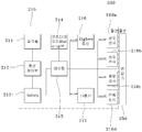
도 1은 본 발명의 실시 예에 따른 태양광장치 모니터링시스템을 개략적으로 나타내는 도면이다. 도 2는 본 발명의 실시 예에 다른 태양광장치 모니터링시스템 중 태양광장치(200)의 구성을 나타내는 도면이다. 1 is a view schematically showing a solar system monitoring system according to an embodiment of the present invention. 2 is a view showing the configuration of the
도 1 및 도 2를 참조하면, 태양광장치 모니터링시스템은 송신제어단말(100) 및 태양광장치(200)를 포함한다. 1 and 2, the photovoltaic device monitoring system includes a
송신제어단말(100)은 태양광장치(200)에 대한 전압, 전류 모니터링, 태양광장치(200) 내의 변압기(250)에 대한 온도, 습도, 풍속(풍향), 일사량 센싱데이터 수집, 특정 고주파 측정(이상 신호측정), IR신호로 웨이크업, 지그비로 데이터 송수신, 자동차에서 작업자가 이동하면서 변압기 진단 가능한 기능을 제공한다.
송신제어단말(100)은 태양광 가로등, 변압기 등과 같이 독립되어 있는 태양광장치(200)에 대한 원격 상태 모니터링을 제공하기 위해 사용된다. 즉, 송신제어단말(100)을 소지한 작업자가 사람이 통행 가능한 곳에 설치되어 있는 도로를 이동하면서 각각의 태양광장치(200)에 대한 점검이 가능하도록 송신제어단말(100)은 소형으로 제작된다. The
태양광장치(200)는 수신제어장치(210) 및 변압기(250)를 포함한다. 수신제어장치(210)는 솔라셀(211), 충전제어부(212), 배터리(213), 포토다이오드웨이크업부(214), 마이컴(215), 지그비통신부(216), IR통신부(217), 온도센서(218a), 습도센서(218b), 풍향센서(218c), 전류센서(218d)를 포함한다. The
적업자가 송신제어단말(100)을 이용해 IR 광선(적외선 광선)을 발사하여 해당 변압기(250)의 모니터링 시스템인 수신제어장치(210)를 웨이크업한다. 웨이크업된 수신제어장치(210)의 마이컴(215)은 지그비통신부(216) 및 센서들(218: 218a, 218b, 218c, 218d)을 작동 온(ON)하여 상태를 체크한 후, 점검하는 작업자에게 상태를 전송하여 이상 유무를 판단하게 한다. The right operator fires an IR ray (infrared ray) using the
솔라셀(211)은 태양에너지를 집광하는 태양전지부로 전력을 충전하여 추가적인 전력선 등과 같이 설비 없이 수신제어장치(200)의 독립적인 형성이 가능하도록 한다. 솔라셀(211)은 충전제어부(212)의 제어에 따라 집광된 태양에너지를 전기에너지로 변환되면 배터리(213)로 전력을 공급한다. The
충전제어부(212)은 솔라셀(211)에 충전된 태양에너지를 전기에너지로 변환시켜 배터리(213)로 제공하며, 솔라셀(211)에 과부하가 걸리지 않도록 하는 제어기능을 수행한다. The charging
배터리(213)는 슈퍼콘덴서로 형성될 수 있으며, 충전제어부(212)의 제어에 따라 전기에너지를 공급받아 저장하며, 포토다이오드웨이크업부(214), 마이컴(215), 지그비통신부(216), IR통신부(217), 온도센서(218a), 습도센서(218b), 풍향센서(218c), 전류센서(218d)에 필요한 전력을 공급한다. The
포토다이오드웨이크업부(214)는 적외선과 포토다이오드를 이용하며, 초절전 상태 감시 기술을 위해 형성되며, 송신제어단말(100)로부터 IR신호인 웨이크업을 수신한다. 포토다이오드웨이크업부(214)는 웨이크업 수신을 마이컴(215)으로 알려 슬립모드에서 웨이크업모드로 변환하도록 한다. The photodiode wake-up
마이컴(215)은 송신제어단말(100)을 소지한 작업자가 상태 점검을 위하여 호출하기 전까지는 슬립모드(Sleep Mode)로 대기하도록 하며, 배터리(213)로부터 각 구성요소로의 전력을 차단함으로써, 수신제어장치(210)의 전력 소비를 줄이도록 한다. 마이컴(215)은 송신제어단말(100)을 소지한 작업자가 호출하지 않은 한 최대 절던 모드로 들어가 수㎂만 소비하며 대기하도록 수신제어장치(210)를 제어한다. 종래의 RF무선방식은 수신 상태를 유지하기 위하여 최소 수십㎃의 소비 전력이 발생하는 반면, 본 발명인 수신제어장치(100)에서 사용되는 적외선 방식은 수㎂ 또는 수십 ㎂의 전력소비면 충분한 장점이 있다. The
마이컴(215)은 수신제어장치(210)에 대한 자동 웨이크업(Wake-up)을 하루에 한번 내지 두번 작동하여 센서들(218: 218a, 218b, 218c, 218d)을 작동시켜 태양광장치(200)에 대한 상태를 체크(Check)하여 메모리(미도시)에 저장한다. The
즉, 마이컴(215)은 변압기(250)의 상태를 모니터링하기 위하여 필요한 전원을 제공하기 위해 태양광 솔라셀(211)을 이용한다.That is, the
마이컴(215)은 평상시 솔라셀(211)을 이용하여 슈퍼 콘덴서 또는 배터리(213)에 전원을 충전하며, 동시에 변압기(250)의 상태를 간헐적으로 모니터링한 후 상태를 메모리(미도시)에 저장하며, 모니터링 하지 않을 시에는 초절전 대기 모드로 전환하여 소비 전력을 최소화시킨다. The
마이컴(215)은 상태 점검을 위하여 송신제어단말(100)을 소지한 작업자가 요청이 있을시 포토다이오드웨이크업부(214)를 통한 웨이크업(Wakeup) 회로에 의한 통지에 따라 동작을 시작하며 지그비통신부(216)을 통한 무선 통신을 이용하여 작업자와 통신하며 현재 메모리에 기록되어 있는 변압기(250)의 상태를 전송한다. 이와 같이, 시스템에 따라 수신제어장치(210)는 소비 전력을 최소화하여 소비 전력을 줄임으로 인하여 솔라셀(211) 크기를 줄일 수 있을 뿐만 아니라 전반적인 시스템 가격을 낮출 수 있어 빠른 상용화를 이룰 수가 있다. 또한, 장마철 해가 오래 뜨지 않은 상황에서도 수십 일을 대기할 수가 있는 장점이 있다. The
지그비통신부(216)는 마이컴(215)의 제어에 따라 웨이크업 상태 또는 하루에 한두 번 주기적으로 메모리에 저장된 변압기(250)의 상태정보를 송신제어단말(100)로 전송한다. 여기서 지그비를 이용함으로써, 기존의 IR 통신 방법에 소비 전력이 약간 많지만 지그비 기술을 사용하여 500㎂의 소비 전력을 사용하면서도 이상이 발생하면 송신제어단말(100)을 소지한 작업자로 하여금 즉시 고장 발생 사실을 알려 수리할 수 있도록 하는 기술이다.The
IR통신부(217)는 지그비통신부(216)와 동일한 기능을 수행하지며, IR 통신 방법을 사용함으로, 보조적으로 사용되며, 수신제어장치(100) 상에서는 지그비와 IR통신 중 하나만 선택 사용하도록 설계된다. The
온도센서(218a)는 마이컴(215)의 요청에 따라 변압기(250)에 대한 온도데이터를 수집하여 마이컴(215)으로 전송한다. The
습도센서(218b)는 마이컴(215)의 요청에 따라 변압기(250)에 대한 습도데이터를 수집하여 마이컴(215)으로 전송한다. The
풍향센서(218c)는 마이컴(215)의 요청에 따라 변압기(250)에 대한 풍속(풍향)데이터를 수집하여 마이컴(215)으로 전송한다. The
전류센서(218d)는 마이컴(215)의 요청에 따라 변압기(250)에 대한 전류의 흐름, 일사량데이터 및 특정 고주파 측정(이상 신호측정)를 수집하여 마이컴(215)으로 전송한다. The
이와 같은 구성에 의해, 수신제어장치(210)는 무선 방식에 비해 초저가로 절전 기능을 이룰 수가 있다. RF 무선 방식은 평상시 대기 소모 전류가 약 30~50㎃ 인데 반해 본 발명에 따른 IR(적외선) 및 포토다이오드를 이용한 기술을 이용하면 최소 0.01㎃(10㎂) ~ 0.3㎃(300㎂)로도 가능하다. 이것은 무선에 비해 최고 3000배 최저 100배 적은 전력을 소모하게 된다. 또한, 무선 장치에 비해 가격은 1/10 이하의 가격으로 개발할 수가 있어 모든 면에서 기존 개발된 제품에 비하여 친환경 및 보급형 제품이 가능하다.
By such a configuration, the
도 3은 본 발명의 실시예에 따른 수신제어장치(210)의 웨이크업 및 슬립상태를 설명하기 위한 도면이다. 도 4는 본 발명의 실시예에 따른 수신제어장치(210)의 회로도이다. 도 1 내지 도 4를 참조하면, 수신제어장치(210)의 적외선수신부인 포토다이오드웨이크업부(214)는 적외선을 수신하면 제 1 모노스테이블(#1) 및 제 2 모노스테이블(#2)을 이용해 바이너리카운터(#3)를 통해 마이컴(215)으로 웨이크업 신호를 전송한다. 3 is a view for explaining a wake-up and sleep state of the
도 3(b)를 참조하면, 정상 56KHz입력인 웨이크업 상태의 경우 제 1 모노스테이블(#1)로의 입력상태는 모든 주기에 동일한 클럭신호로 유지되며, 제 2 모노스테이블(#2)로의 입력상태는 제 1 모노스테이블(#1)에 대한 5주기 동안 한 번의 리셋(RESET) 펄스 뒤, 마지막 주기에서 오프로 하락되는 상태로 진행한다. . Referring to FIG. 3B, in the wake-up state of a normal 56 KHz input, the input state to the first
한편, 비정상 신호 입력의 경우, 제 1 모노스테이블(#1)로의 입력상태는 5주기 중 4번째 주기에서 (+)펄스가 인가되지 않는 상태이며, 제 2 모노스테이블(#2)로의 입력상태는 정상 56KHz입력인 웨이크업 상태와 다르게 리셋(RESET) 펄스가 일어나지 않는 상태로 유지된다.
On the other hand, in the case of an abnormal signal input, the input state to the first monostable (# 1) is a state in which the (+) pulse is not applied in the fourth period of five periods, the input to the second monostable (# 2) Unlike the wake-up state, which is a normal 56KHz input, the state remains without a reset pulse.
도 4의 회로도를 참조로 보다 구체적으로 살펴보면, 수신제어장치(210)의 포토다이오드웨이크업부(214)의 PD1의 적외선 수신에서 설정된 주파수가 C4를 통해 들어온다. 여기서, C4의 시정수 만큼의 대역폭만 수신하며, 대역폭은 56KHz에서 +/- 10%로 설정된다. 1차 Q3에서 증폭을 하고 2차 Q1에서 증폭을 하여 U2를 통하여 최종 대역 폭만 수신하게 된다. 2개의 단안정 멀티바이브레이터를 이용하여 긴 주기를 갖는 U2B의 펄스와 짧은 주기를 갖는 단안정 멀티바이브레이터를 두어 U2의 주기 안에 U1의 펄스(pulse)가 5개 이상이 들어오면 U3 카운터에 의해 카운트 되어 Q2를 동작시켜 마이컴(215)의 리셋(Reset)을 로우(Low)로 하여 슬립모드(Sleep Mode)에서 깨어나게 한다.Referring to the circuit diagram of FIG. 4, the frequency set in the infrared reception of PD1 of the photodiode wake-up
그러면 마이컴(215)은 추가적인 리셋을 막고 데이터 수신 모드로 들어가서 작업자의 송신제어단말(100)과 통신하게 된다.The
이와 같은 초절전 회로 설계를 통해 일반 씨모스 로직 아이씨(CMOS Logic IC)들은 평상시 소비 전력이 수십㎂정도 되므로 위 회로를 이용하여 구성시 수십㎂이내의 대기 전력으로 설계가 가능하여 작은 솔라셀(211)로 한번 충전시 오랜 기간 대기할 수가 있어 무전원 공급 장치인 태양광장치(200)의 모니터링에 최적인 회로가 설계가 가능하다.The CMOS power ICs have a power consumption of about several tens of normal power through the design of the ultra-low power circuit, and thus, a small
본 설계 회로의 소비전력은 시뮬레이션 결과 하기의 표와 같다. The power consumption of this design circuit is shown in the following table as a result of the simulation.
즉, U2는 7㎂, U1와 U2(한 개의 IC임)는 20㎂, U3는 20㎂, U4는 1㎂, 기타 2㎂로 토탈(Total) 약 50㎂ 정도의 대기 전력으로 사용가능하다. 기타 다른 장치들은 마이컴(215)이 스립모드(Sleep Mode)로 들어가기 전 모두 오프(Off)하여 대기 전력이 없다.
In other words, U2 is 7kW, U1 and U2 (one IC) is 20kW, U3 is 20kW, U4 is 1kW and other 2kW. The other devices are all off before the
도 5는 본 발명의 실시예에 따른 태양광장치 모니터링시스템의 통신방법을 설명하기 위한 도면이다. 먼저, 도 5(a)는 제 1 통신방법으로 IR 신호에 의해 변압기(250)에 연결된 수신제어장치(210)를 웨이크업하고, IR로 통신하는 경우의 약식 구성도를 나타낸다. 그리고, 도 5(b)는 제 2 통신방법으로 IR 신호에 의해 변압기(250)에 연결된 수신제어장치(210)를 웨이크업하고, 지그비 방식으로 통신하는 경우의 약식 구성도를 나타낸다.
5 is a view for explaining a communication method of the photovoltaic device monitoring system according to an embodiment of the present invention. First, FIG. 5 (a) shows a simplified configuration diagram when a wake-up
도 6은 본 발명의 실시예에 따른 태양광장치 모니터링시스템에 사용되는 홀센서(10)를 설명하기 위한 도면이다. 도 1 내지 도 6을 참조하면, 수신제어장치(210)와 변압기(250) 사이에 홀센서(Hole Sensor: 10)가 더 포함될 수 있다. 6 is a view for explaining the
홀센서(10)는 전기선을 절단하지 않고 홀센서 중앙으로 전기선을 통과시켜 부하가 유도되는 기전력으로 소비전력을 측정하여 수신제어장치(210)의 마이컴(315)을 전송하는 방식을 사용한다.
도 7은 본 발명의 실시예에 따른 태양광장치 모니터링방법을 나타내는 흐름도이다. 도 1 내지 도 7을 참조하면, 수신제어장치(210)는 송신제어단말(100)로부터 호출되었는지 여부를 판단한다(S1). 7 is a flowchart illustrating a photovoltaic device monitoring method according to an embodiment of the present invention. 1 to 7, the
단계(S1)의 판단결과 호출되지 않은 경우, 수신제어장치(210)는 배터리(213)로부터 내부구성요소(포토다이오드웨이크업부(214), 마이컴(215), 지그비통신부(216), IR통신부(217), 온도센서(218a), 습도센서(218b), 풍향센서(218c), 전류센서(218d))로 공급되는 전원을 오프(OFF)하고, 마이컴(215)을 슬립모드(Sleep Mode)로 진입시킨다(S2).When the determination result of step S1 is not called, the
한편, 단계(S1)의 판단결과 호출된 경우 배터리(213)로부터 내부구성요소(포토다이오드웨이크업부(214), 마이컴(215), 지그비통신부(216), IR통신부(217), 온도센서(218a), 습도센서(218b), 풍향센서(218c), 전류센서(218d))로 공급되는 전원을 온(ON)하고, 마이컴(215)을 웨이크업한다(S3). On the other hand, when it is called as a result of the determination of step S1 from the
이에 따라, 마이컴(215)은 IR통신부(217) 또는 지그비통신부(216)를 통해 송신제어단말(100)로 통신시도 가능여부를 판단한다(S4). 마이컴(215)은 지그비통신부(216)를 우선순위로, IR통신부(217)를 차순위로 하여 지그비통신부(216)에 의한 통신시도 가능할 경우 먼저 통신시도를 한다. Accordingly, the
단계(S4)의 판단결과 통신시도가 불가능한 경우, 수신제어장치(210)는 단계(S2)로 회귀한다.If the communication attempt is impossible as a result of the determination in step S4, the
한편, 단계(S4)의 판단결과 통신시도가 가능한 경우, 수신제어장치(210)의 마이컴(215)은 원격장치인 송신제어단말(100)의 요구사항인 센서들(218)로부터 수신된 데이터를 송신제어단말(100)로 전송한다(S5).On the other hand, if the communication attempt is possible as a result of the determination in step S4, the
단계(S5) 이후, 마이컴(215)는 요구사항이 완료되었는지 여부를 판단한 뒤(S6), 모두 완료된 경우 단계(S2)로 회귀하여 슬립모드(Sleep Mode)로 재진입한다.After step S5, the
한편, 단계(S6)에서 요구사항이 모두 완료되지 않은 경우 마이컴(215)은 단계(S4)로 회귀하여 단계(S4 내지 S6)를 반복수행한다.
On the other hand, when all of the requirements are not completed in step S6, the
이상과 같이, 본 명세서와 도면에는 본 발명의 바람직한 실시 예에 대하여 개시하였으며, 비록 특정 용어들이 사용되었으나, 이는 단지 본 발명의 기술 내용을 쉽게 설명하고 발명의 이해를 돕기 위한 일반적인 의미에서 사용된 것이지, 본 발명의 범위를 한정하고자 하는 것은 아니다. 여기에 개시된 실시 예 외에도 본 발명의 기술적 사상에 바탕을 둔 다른 변형 예들이 실시 가능하다는 것은 본 발명이 속하는 기술 분야에서 통상의 지식을 가진 자에게 자명한 것이다.
As described above, the specification and the drawings have been described with respect to the preferred embodiments of the present invention, although specific terms are used, it is only used in a general sense to easily explain the technical contents of the present invention and to help the understanding of the invention. It is not intended to limit the scope of the present invention. It will be apparent to those skilled in the art that other modifications based on the technical idea of the present invention can be carried out in addition to the embodiments disclosed herein.
100: 송신제어단말 200: 태양광장치
210: 수신제어장치 211: 솔라셀
212: 충전제어부 213: 배터리
214: 포토다이오드웨이크업부 215: 마이컴
216: 지그비통신부 217: IR통신부
218: 센서들 218a: 온도센서
218b: 습도센서 218c: 풍향센서
218d: 전류센서 250: 변압기100: transmission control terminal 200: photovoltaic device
210: reception control device 211: solar cell
212: charge control unit 213: battery
214: photodiode wake-up unit 215: microcomputer
216: Zigbee communication unit 217: IR communication unit
218:
218b:
218d: current sensor 250: transformer
Claims (9)
상기 태양광장치는, 변압기; 그리고 상기 작업자에 의한 상기 송신제어단말을 이용한 IR 광선을 발사에 따른 상기 변압기를 모니터링하기 위한 수신제어장치; 를 포함하는 태양광장치 모니터링시스템에 있어서, 상기 수신제어장치는,
상기 송신제어단말로부터 상기 IR 광선 수신에 따른 웨이크업 상태가 호출되었는지를 판단하는 마이컴; 을 포함하며,
상기 마이컴은, 상기 호출에 따라 웨이크업된 경우 IR통신부 및 지그비통신부 중 상기 지그비통신부를 우선순위, 상기 IR통신부를 차순위로 하여 상기 송신제어단말로 통신시도 가능여부를 판단하여 통신시도가 가능한 경우, 상기 송신제어단말의 요구사항인 온도센서, 습도센서, 풍향센서, 전류센서로부터 각각 센싱된 상기 변압기의 온도, 습도, 풍향, 전류를 측정한 데이터를 상기 송신제어단말로 전송하며,
상기 호출된 경우 배터리로부터, 상기 IR 광선을 수신하는 포토다이오드웨이크업부, 그리고 상기 지그비통신부, 상기 IR통신부, 상기 온도센서, 상기 습도센서, 상기 풍향센서, 상기 전류센서로 공급되는 전원을 온(ON)시키는 것을 특징으로 하는 변압기를 포함하는 태양광장치 모니터링시스템.
Photovoltaic devices; And a transmission control terminal for providing a remote status monitoring for the photovoltaic device to the worker as a terminal possessed by the worker. Lt; / RTI >
The solar device, a transformer; And a reception control apparatus for monitoring the transformer according to the firing of the IR light by the operator using the transmission control terminal; In the photovoltaic device monitoring system comprising: the reception control device,
A microcomputer that determines whether a wake-up state according to the IR light reception is called from the transmission control terminal; Including;
When the microcomputer wakes up according to the call, when the communication attempt is possible by determining whether the ZigBee communication unit is the priority of the IR communication unit and the ZigBee communication unit and the IR communication unit is the next priority, it is possible to communicate with the transmission control terminal. Transmitting the data of the temperature, humidity, wind direction, and current of the transformer sensed from the temperature sensor, the humidity sensor, the wind direction sensor, and the current sensor, which are the requirements of the transmission control terminal, to the transmission control terminal,
The photodiode wake-up unit, which receives the IR light from the battery, and the Zigbee communication unit, the IR communication unit, the temperature sensor, the humidity sensor, the wind direction sensor, the current sensor when the call is turned on (ON) Photovoltaic device monitoring system comprising a transformer characterized in that.
상기 송신제어단말로부터 호출되지 않은 경우, 상기 배터리로부터 내부구성요소로 공급되는 전원을 오프(OFF)하고, 슬립모드(Sleep Mode)로 진입되는 것을 특징으로 하는 변압기를 포함하는 태양광장치 모니터링시스템.
The method of claim 1, wherein the microcomputer
When not called from the transmission control terminal, the power supply to the internal component from the battery (OFF) off, and enters the sleep mode (Sleep Mode), characterized in that the solar device monitoring system comprising a transformer.
솔라셀로부터 전력을 충전하며,
상기 포토다이오드웨이크업부는 상기 송신제어단말로부터 호출여부를 탐지하는 것을 특징으로 하는 변압기를 포함하는 태양광장치 모니터링시스템.
The method of claim 1, wherein the battery,
To charge power from the cell,
And the photodiode wake-up unit detects whether a call is made from the transmission control terminal.
평상시 상기 솔라셀을 이용하여 상기 배터리에 전원을 충전하며, 동시에 상기 변압기의 상태를 간헐적으로 모니터링한 후 상태를 메모리 저장하며, 모니터링 하지 않을 시에는 초절전 대기 모드로 전환하여 소비 전력을 최소화하는 것을 특징으로 하는 변압기를 포함하는 태양광장치 모니터링시스템.
The method of claim 3, wherein the microcomputer,
Charging power to the battery using the solar cell at the same time, and at the same time intermittently monitors the state of the transformer and stores the state in memory, and when not monitored, the power saving mode by minimizing power consumption by switching to the ultra-low standby mode. Photovoltaic device monitoring system comprising a transformer.
상기 센서들의 상태 점검을 위하여 상기 송신제어단말을 소지한 작업자가 요청이 있을시 상기 포토다이오드웨이크업부를 통한 웨이크업(Wakeup) 회로에 의한 통지에 따라 동작을 시작하며 상기 지그비통신부를 통한 무선 통신을 이용하여 상기 작업자와 통신하며 상기 메모리에 기록되어 있는 상기 변압기의 상태를 전송하는 것을 특징으로 하는 변압기를 포함하는 태양광장치 모니터링시스템.
The method of claim 4, wherein the microcomputer,
When a worker carrying the transmission control terminal checks the state of the sensors, the operator starts the operation according to the notification by the wakeup circuit through the photodiode wake-up unit and performs wireless communication through the Zigbee communication unit. And a transformer for communicating with the operator and transmitting the state of the transformer recorded in the memory.
상기 포토다이오드웨이크업부의 PD1의 적외선 수신에서 설정된 주파수가 C4를 통해 들어오며, 1차 Q3에서 증폭을 하고 2차 Q1에서 증폭을 하여 U2를 통하여 최종 대역 폭만 수신하게 되며, 2개의 단안정 멀티바이브레이터를 이용하여 긴 주기를 갖는 U2B의 펄스와 짧은 주기를 갖는 단안정 멀티바이브레이터를 두어 U2의 주기 안에 U1의 펄스(pulse)가 5개 이상이 들어오면 U3 카운터에 의해 카운트 되어 Q2를 동작시켜 상기 마이컴의 리셋(Reset)을 로우(Low)로 하여 슬립모드(Sleep Mode)에서 깨어나게 하는 것을 특징으로 하는 변압기를 포함하는 태양광장치 모니터링시스템.
The method of claim 5, wherein the reception control device,
The frequency set in the infrared reception of the PD1 of the photodiode wake-up unit comes in through C4, amplifies in the first Q3, amplifies in the second Q1, and receives only the final bandwidth through U2, two monostable multivibrators By using U2B pulse with long period and monostable multivibrator with short period, if more than 5 pulses of U1 enter within U2 period, it is counted by U3 counter to operate Q2. A photovoltaic device monitoring system comprising a transformer to wake up in a sleep mode by setting Reset to Low.
상기 마이컴이, IR통신부 및 지그비통신부 중 상기 지그비통신부를 우선순위, 상기 IR통신부를 차순위로 하여 상기 송신제어단말로 통신시도 가능여부를 판단하여 통신시도가 가능한 경우, 상기 송신제어단말의 요구사항인 센서들로부터 수신된 데이터를 상기 송신제어단말로 전송하는 제 2 단계; 및
상기 마이컴이, 상기 요구사항이 완료되었는지 여부를 판단한 뒤, 모두 완료된 경우 슬립모드(Sleep Mode)로 진입하는 제 3 단계; 를 포함하는 것을 특징으로 하는 변압기를 포함하는 태양광장치 모니터링방법.
A first step of determining whether the reception control device is called from the transmission control terminal, when called, to turn on the power supplied from the battery to the internal component, and to wake up the microcomputer;
If the microcomputer determines that the ZigBee communication unit is the priority among the IR communication unit and the ZigBee communication unit and the IR communication unit is the next priority, it is determined that the microcommunication can be attempted to communicate with the transmission control terminal. A second step of transmitting data received from sensors to the transmission control terminal; And
Determining, by the microcomputer, whether or not the requirement is completed and entering a sleep mode when all of the requirements are completed; Photovoltaic device monitoring method comprising a transformer comprising a.
상기 송신제어단말로부터 호출되지 않은 경우, 상기 수신제어장치가, 상기 배터리로부터 상기 내부구성요소로 공급되는 전원을 오프(OFF)하고, 상기 마이컴을 상기 슬립모드(Sleep Mode)로 진입시키는 것을 특징으로 하는 변압기를 포함하는 태양광장치 모니터링방법.
8. The method of claim 7, wherein in the first step:
When not called from the transmission control terminal, the reception control device, characterized in that the power supplied to the internal component from the battery (OFF) (OFF), and enters the microcomputer into the sleep mode (Sleep Mode), characterized in that Solar device monitoring method comprising a transformer to.
솔라셀로부터 전력을 충전하며,
상기 내부구성요소는, 포토다이오드웨이크업부, 상기 마이컴, 상기 지그비통신부, 상기 IR통신부, 그리고 상기 센서들인 온도센서, 습도센서, 풍향센서, 전류센서를 포함하며, 상기 포토다이오드웨이크업부는 상기 송신제어단말로부터 호출여부를 탐지하는 것을 특징으로 하는 변압기를 포함하는 태양광장치 모니터링방법.
The method of claim 7, wherein the battery,
To charge power from the cell,
The internal component includes a photodiode wake-up unit, the microcomputer, the Zigbee communication unit, the IR communication unit, and the sensors, the temperature sensor, humidity sensor, wind direction sensor, current sensor, the photodiode wake-up unit is the transmission control Solar device monitoring method comprising a transformer for detecting whether or not the call from the terminal.
Priority Applications (1)
| Application Number | Priority Date | Filing Date | Title |
|---|---|---|---|
| KR1020100104433A KR101008202B1 (en) | 2010-10-26 | 2010-10-26 | Photovoltaic device monitoring system and monitoring method including transformer |
Applications Claiming Priority (1)
| Application Number | Priority Date | Filing Date | Title |
|---|---|---|---|
| KR1020100104433A KR101008202B1 (en) | 2010-10-26 | 2010-10-26 | Photovoltaic device monitoring system and monitoring method including transformer |
Publications (1)
| Publication Number | Publication Date |
|---|---|
| KR101008202B1 true KR101008202B1 (en) | 2011-01-17 |
Family
ID=43616290
Family Applications (1)
| Application Number | Title | Priority Date | Filing Date |
|---|---|---|---|
| KR1020100104433A Expired - Fee Related KR101008202B1 (en) | 2010-10-26 | 2010-10-26 | Photovoltaic device monitoring system and monitoring method including transformer |
Country Status (1)
| Country | Link |
|---|---|
| KR (1) | KR101008202B1 (en) |
Cited By (4)
| Publication number | Priority date | Publication date | Assignee | Title |
|---|---|---|---|---|
| KR101374830B1 (en) | 2012-02-21 | 2014-03-17 | 울산대학교 산학협력단 | Apparatus and Method for Controlling Energy Supply with Sensor Node |
| KR101672030B1 (en) * | 2016-04-29 | 2016-11-02 | 편도균 | Apparatus for informing electric transformer short and incline of utility pole |
| WO2020046004A1 (en) * | 2018-08-30 | 2020-03-05 | 엘지이노텍 주식회사 | Dc-dc converter for solar power-linked energy storage system, and control method therefor |
| CN118646163A (en) * | 2024-08-13 | 2024-09-13 | 江苏大淀能源科技有限公司 | Electric energy meter and concentrator control method based on distributed photovoltaics |
Citations (4)
| Publication number | Priority date | Publication date | Assignee | Title |
|---|---|---|---|---|
| KR100705442B1 (en) * | 2004-12-23 | 2007-04-10 | 한국전자통신연구원 | Mobile communication terminal using sleep mode method and sleep mode method |
| US7319574B2 (en) * | 2005-05-23 | 2008-01-15 | Eaton Corporation | Arc fault detection apparatus, method and system for an underground electrical conductor |
| US20090278479A1 (en) * | 2008-05-06 | 2009-11-12 | Platner Brian P | Networked, wireless lighting control system with distributed intelligence |
| US20100182160A1 (en) * | 2009-01-21 | 2010-07-22 | Ming-Wei Lu | Remote control with passive RFID tag and Zigbee arrangement |
-
2010
- 2010-10-26 KR KR1020100104433A patent/KR101008202B1/en not_active Expired - Fee Related
Patent Citations (4)
| Publication number | Priority date | Publication date | Assignee | Title |
|---|---|---|---|---|
| KR100705442B1 (en) * | 2004-12-23 | 2007-04-10 | 한국전자통신연구원 | Mobile communication terminal using sleep mode method and sleep mode method |
| US7319574B2 (en) * | 2005-05-23 | 2008-01-15 | Eaton Corporation | Arc fault detection apparatus, method and system for an underground electrical conductor |
| US20090278479A1 (en) * | 2008-05-06 | 2009-11-12 | Platner Brian P | Networked, wireless lighting control system with distributed intelligence |
| US20100182160A1 (en) * | 2009-01-21 | 2010-07-22 | Ming-Wei Lu | Remote control with passive RFID tag and Zigbee arrangement |
Cited By (6)
| Publication number | Priority date | Publication date | Assignee | Title |
|---|---|---|---|---|
| KR101374830B1 (en) | 2012-02-21 | 2014-03-17 | 울산대학교 산학협력단 | Apparatus and Method for Controlling Energy Supply with Sensor Node |
| KR101672030B1 (en) * | 2016-04-29 | 2016-11-02 | 편도균 | Apparatus for informing electric transformer short and incline of utility pole |
| WO2020046004A1 (en) * | 2018-08-30 | 2020-03-05 | 엘지이노텍 주식회사 | Dc-dc converter for solar power-linked energy storage system, and control method therefor |
| US11962232B2 (en) | 2018-08-30 | 2024-04-16 | Lg Innotek Co., Ltd. | DC-dC converter for solar power-linked energy storage system, and control method therefor |
| CN118646163A (en) * | 2024-08-13 | 2024-09-13 | 江苏大淀能源科技有限公司 | Electric energy meter and concentrator control method based on distributed photovoltaics |
| CN118646163B (en) * | 2024-08-13 | 2024-12-10 | 江苏大淀能源科技有限公司 | Electric energy meter and concentrator control method based on distributed photovoltaic |
Similar Documents
| Publication | Publication Date | Title |
|---|---|---|
| CN102830661B (en) | House control system and appliance control method | |
| CN102879117B (en) | Electric field induction powered disconnector contact temperature online measurement and wireless transmission device | |
| AU2007356889A2 (en) | System and method for transferring electrical power between grid and vehicle | |
| JP5816545B2 (en) | Wireless sensor system | |
| KR101008202B1 (en) | Photovoltaic device monitoring system and monitoring method including transformer | |
| US10998758B2 (en) | Power supply apparatus and electricity storage device | |
| CN103634572A (en) | Communication system for video monitoring based intelligent power transmission line patrolling | |
| CN103986416A (en) | Portable photovoltaic assembly monitoring end | |
| CN110345916A (en) | A kind of shaft tower gradient detection system and method | |
| JP2010055356A (en) | Facility data collection system | |
| CN108495286A (en) | A kind of system for realizing seamless railway rail status monitoring master control set low-power consumption | |
| CN102377249B (en) | Sensor system integrating wireless energy transmitter and receiver | |
| CN118801333A (en) | Microgrid power transmission control method and system | |
| CN217720819U (en) | Fill electric pile's power down data protection circuit | |
| EP2902792A1 (en) | Power measurement | |
| JP6808973B2 (en) | Call device, call method, and program | |
| CN215340046U (en) | Intelligent lightning current detection system | |
| CN210321718U (en) | Tower gradient detection system | |
| KR101223920B1 (en) | The apparatus of monitoring for being most suitable control | |
| CN212162919U (en) | A high-power grid-connected energy management system | |
| KR20220073944A (en) | Self-Powered Wireless Sensor | |
| KR20180105832A (en) | Wireless remote metering system and method | |
| Lu et al. | Substation equipment temperature monitoring system design based on self-powered wireless temperature sensors | |
| Zeng et al. | Design and Research of a Self-Powered Temperature Measurement System for Transmission Line Condition Monitoring | |
| CN205120893U (en) | Power transmission line fault indictor |
Legal Events
| Date | Code | Title | Description |
|---|---|---|---|
| A201 | Request for examination | ||
| PA0109 | Patent application |
St.27 status event code: A-0-1-A10-A12-nap-PA0109 |
|
| PA0201 | Request for examination |
St.27 status event code: A-1-2-D10-D11-exm-PA0201 |
|
| A302 | Request for accelerated examination | ||
| PA0302 | Request for accelerated examination |
St.27 status event code: A-1-2-D10-D17-exm-PA0302 St.27 status event code: A-1-2-D10-D16-exm-PA0302 |
|
| E902 | Notification of reason for refusal | ||
| PE0902 | Notice of grounds for rejection |
St.27 status event code: A-1-2-D10-D21-exm-PE0902 |
|
| P11-X000 | Amendment of application requested |
St.27 status event code: A-2-2-P10-P11-nap-X000 |
|
| P13-X000 | Application amended |
St.27 status event code: A-2-2-P10-P13-nap-X000 |
|
| E701 | Decision to grant or registration of patent right | ||
| PE0701 | Decision of registration |
St.27 status event code: A-1-2-D10-D22-exm-PE0701 |
|
| GRNT | Written decision to grant | ||
| PR0701 | Registration of establishment |
St.27 status event code: A-2-4-F10-F11-exm-PR0701 |
|
| PR1002 | Payment of registration fee |
St.27 status event code: A-2-2-U10-U11-oth-PR1002 Fee payment year number: 1 |
|
| PG1601 | Publication of registration |
St.27 status event code: A-4-4-Q10-Q13-nap-PG1601 |
|
| FPAY | Annual fee payment |
Payment date: 20140103 Year of fee payment: 4 |
|
| PR1001 | Payment of annual fee |
St.27 status event code: A-4-4-U10-U11-oth-PR1001 Fee payment year number: 4 |
|
| FPAY | Annual fee payment |
Payment date: 20141229 Year of fee payment: 5 |
|
| PR1001 | Payment of annual fee |
St.27 status event code: A-4-4-U10-U11-oth-PR1001 Fee payment year number: 5 |
|
| FPAY | Annual fee payment |
Payment date: 20160210 Year of fee payment: 6 |
|
| PR1001 | Payment of annual fee |
St.27 status event code: A-4-4-U10-U11-oth-PR1001 Fee payment year number: 6 |
|
| R18-X000 | Changes to party contact information recorded |
St.27 status event code: A-5-5-R10-R18-oth-X000 |
|
| P22-X000 | Classification modified |
St.27 status event code: A-4-4-P10-P22-nap-X000 |
|
| FPAY | Annual fee payment |
Payment date: 20170110 Year of fee payment: 7 |
|
| L13-X000 | Limitation or reissue of ip right requested |
St.27 status event code: A-2-3-L10-L13-lim-X000 |
|
| PR1001 | Payment of annual fee |
St.27 status event code: A-4-4-U10-U11-oth-PR1001 Fee payment year number: 7 |
|
| U15-X000 | Partial renewal or maintenance fee paid modifying the ip right scope |
St.27 status event code: A-4-4-U10-U15-oth-X000 |
|
| FPAY | Annual fee payment |
Payment date: 20180103 Year of fee payment: 8 |
|
| PR1001 | Payment of annual fee |
St.27 status event code: A-4-4-U10-U11-oth-PR1001 Fee payment year number: 8 |
|
| P22-X000 | Classification modified |
St.27 status event code: A-4-4-P10-P22-nap-X000 |
|
| R18-X000 | Changes to party contact information recorded |
St.27 status event code: A-5-5-R10-R18-oth-X000 |
|
| FPAY | Annual fee payment |
Payment date: 20190122 Year of fee payment: 9 |
|
| PR1001 | Payment of annual fee |
St.27 status event code: A-4-4-U10-U11-oth-PR1001 Fee payment year number: 9 |
|
| FPAY | Annual fee payment |
Payment date: 20191223 Year of fee payment: 10 |
|
| PR1001 | Payment of annual fee |
St.27 status event code: A-4-4-U10-U11-oth-PR1001 Fee payment year number: 10 |
|
| PR1001 | Payment of annual fee |
St.27 status event code: A-4-4-U10-U11-oth-PR1001 Fee payment year number: 11 |
|
| PR1001 | Payment of annual fee |
St.27 status event code: A-4-4-U10-U11-oth-PR1001 Fee payment year number: 12 |
|
| PR1001 | Payment of annual fee |
St.27 status event code: A-4-4-U10-U11-oth-PR1001 Fee payment year number: 13 |
|
| PC1903 | Unpaid annual fee |
St.27 status event code: A-4-4-U10-U13-oth-PC1903 Not in force date: 20240108 Payment event data comment text: Termination Category : DEFAULT_OF_REGISTRATION_FEE |
|
| PC1903 | Unpaid annual fee |
St.27 status event code: N-4-6-H10-H13-oth-PC1903 Ip right cessation event data comment text: Termination Category : DEFAULT_OF_REGISTRATION_FEE Not in force date: 20240108 |