KR100825640B1 - Optical information playback device and playback method - Google Patents
Optical information playback device and playback method Download PDFInfo
- Publication number
- KR100825640B1 KR100825640B1 KR1020060092892A KR20060092892A KR100825640B1 KR 100825640 B1 KR100825640 B1 KR 100825640B1 KR 1020060092892 A KR1020060092892 A KR 1020060092892A KR 20060092892 A KR20060092892 A KR 20060092892A KR 100825640 B1 KR100825640 B1 KR 100825640B1
- Authority
- KR
- South Korea
- Prior art keywords
- light
- adjacent
- reproduction light
- optical information
- recording area
- Prior art date
- Legal status (The legal status is an assumption and is not a legal conclusion. Google has not performed a legal analysis and makes no representation as to the accuracy of the status listed.)
- Expired - Fee Related
Links
Images




Classifications
-
- G—PHYSICS
- G11—INFORMATION STORAGE
- G11B—INFORMATION STORAGE BASED ON RELATIVE MOVEMENT BETWEEN RECORD CARRIER AND TRANSDUCER
- G11B7/00—Recording or reproducing by optical means, e.g. recording using a thermal beam of optical radiation by modifying optical properties or the physical structure, reproducing using an optical beam at lower power by sensing optical properties; Record carriers therefor
- G11B7/004—Recording, reproducing or erasing methods; Read, write or erase circuits therefor
- G11B7/0065—Recording, reproducing or erasing by using optical interference patterns, e.g. holograms
-
- G—PHYSICS
- G11—INFORMATION STORAGE
- G11B—INFORMATION STORAGE BASED ON RELATIVE MOVEMENT BETWEEN RECORD CARRIER AND TRANSDUCER
- G11B7/00—Recording or reproducing by optical means, e.g. recording using a thermal beam of optical radiation by modifying optical properties or the physical structure, reproducing using an optical beam at lower power by sensing optical properties; Record carriers therefor
- G11B7/08—Disposition or mounting of heads or light sources relatively to record carriers
- G11B7/09—Disposition or mounting of heads or light sources relatively to record carriers with provision for moving the light beam or focus plane for the purpose of maintaining alignment of the light beam relative to the record carrier during transducing operation, e.g. to compensate for surface irregularities of the latter or for track following
- G11B7/0901—Disposition or mounting of heads or light sources relatively to record carriers with provision for moving the light beam or focus plane for the purpose of maintaining alignment of the light beam relative to the record carrier during transducing operation, e.g. to compensate for surface irregularities of the latter or for track following for track following only
-
- G—PHYSICS
- G11—INFORMATION STORAGE
- G11B—INFORMATION STORAGE BASED ON RELATIVE MOVEMENT BETWEEN RECORD CARRIER AND TRANSDUCER
- G11B7/00—Recording or reproducing by optical means, e.g. recording using a thermal beam of optical radiation by modifying optical properties or the physical structure, reproducing using an optical beam at lower power by sensing optical properties; Record carriers therefor
- G11B7/12—Heads, e.g. forming of the optical beam spot or modulation of the optical beam
- G11B7/135—Means for guiding the beam from the source to the record carrier or from the record carrier to the detector
- G11B7/1365—Separate or integrated refractive elements, e.g. wave plates
-
- G—PHYSICS
- G11—INFORMATION STORAGE
- G11B—INFORMATION STORAGE BASED ON RELATIVE MOVEMENT BETWEEN RECORD CARRIER AND TRANSDUCER
- G11B7/00—Recording or reproducing by optical means, e.g. recording using a thermal beam of optical radiation by modifying optical properties or the physical structure, reproducing using an optical beam at lower power by sensing optical properties; Record carriers therefor
- G11B7/12—Heads, e.g. forming of the optical beam spot or modulation of the optical beam
- G11B7/135—Means for guiding the beam from the source to the record carrier or from the record carrier to the detector
- G11B7/1381—Non-lens elements for altering the properties of the beam, e.g. knife edges, slits, filters or stops
Landscapes
- Physics & Mathematics (AREA)
- Optics & Photonics (AREA)
- Optical Recording Or Reproduction (AREA)
Abstract
본 발명의 광정보 재생장치는 광원, 상기 광원에서 제공한 광에 경로를 제공하고 저장매체까지 입사하게 하는 광학계와 상기 저장매체에서 재생된 재생광에서 선택된 기록영역의 재생광을 검출하는 제 1검출부와 상기 저장매체에서 재생된 재생광을 선택된 기록영역의 재생광과 상기 기록영역과 인접한 인접 기록영역에서 재생된 인접 재생광으로 분리시켜 상기 선택된 기록영역의 재생광은 통과시키고, 상기 인접 재생광은 차폐시키는 광분리부재와 상기 광분리부재에 포함되어 상기 인접 재생광의 광정보를 검출하는 제 2검출부 및 상기 제 2검출부가 검출한 상기 인접 재생광의 광정보를 수신하여 트랙킹 위치를 확인하고, 상기 트랙킹 위치를 제어하는 제어부를 구비한 것으로 이러한 본 발명에 따른 광정보 처리장치는 재생광을 선택된 기록영역의 재생광과 인접 재생광으로 분리함과 동시에 인접 재생광의 광정보 검출하는 광분리부재를 사용하여 광정보 재생장치의 구조를 간단히 하고, 트랙킹 제어에 필요한 재생광을 광분리부재에서 바로 검출하기 때문에 보다 정확한 광정보를 얻을 수 있다. An optical information reproducing apparatus of the present invention comprises a light source, a first detection unit for detecting reproduction light of a recording area selected from an optical system that provides a path to the light provided by the light source and enters a storage medium and reproduction light reproduced from the storage medium. And the reproduction light reproduced from the storage medium into reproduction light of the selected recording area and adjacent reproduction light reproduced from the adjacent recording area adjacent to the recording area to pass the reproduction light of the selected recording area, and the adjacent reproduction light A second detection unit included in the optical separation member for shielding and the optical separation member to detect optical information of the adjacent reproduction light, and optical information of the adjacent reproduction light detected by the second detection unit to receive a tracking position and determine the tracking position The optical information processing apparatus according to the present invention comprises a recording area in which reproduction light is selected. The structure of the optical information reproducing apparatus is simplified by using an optical separation member that separates the reproduction light and the adjacent reproduction light and detects the optical information of the adjacent reproduction light, and detects the reproduction light required for tracking control directly from the optical separation member. Accurate light information can be obtained.
트랙킹, 재생장치, 광정보 Tracking, playback device, optical information
Description
도 1은 본 발명의 일실시예에 따른 광정보 재생장치를 나타낸 개략도이다.1 is a schematic diagram showing an optical information reproducing apparatus according to an embodiment of the present invention.
도 2는 도 1에 도시된 광분리부재를 나타낸 간략도이다.FIG. 2 is a schematic view showing the optical separation member shown in FIG. 1.
도 3a는 광분리부재에 입사된 정확한 트랙킹 위치를 가지는 재생광과 제 2검출부를 나타낸 간략도이다.3A is a simplified diagram showing a regenerated light having a correct tracking position incident on the optical separation member and the second detection unit.
도 3b는 저장매체의 회전으로 제 2검출부와 재생광의 위치가 어긋난 경우를 나타낸 간략도이다. 3B is a simplified diagram illustrating a case where the position of the second detection unit and the reproduction light are shifted due to the rotation of the storage medium.
도 4는 트랙킹 위치가 정확할 때 광정보 저장매체의 회전에 따라 변화되는 광검출량을 도시한 그래프이다. 4 is a graph showing the amount of light detection changed according to the rotation of the optical information storage medium when the tracking position is correct.
도 5a는 광분리부재에 입사된 트랙킹 정상 위치보다 위쪽에 위치한 재생광과 제 2검출부를 나타낸 간략도이다. FIG. 5A is a simplified diagram showing the regenerated light and the second detection unit located above the tracking normal position incident on the optical separation member.
도 5b는 광분리부재에 입사된 재생광이 도 5a의 트랙킹 위치보다 더 위쪽에 위치하여 트랙킹 위치가 최대로 벗어난 경우를 나타낸 간략도이다. FIG. 5B is a simplified diagram illustrating a case in which the reproducing light incident on the optical separation member is located higher than the tracking position of FIG. 5A and thus the tracking position is deviated to the maximum.
도 6은 트랙위치가 정상위치에서 위쪽의 트랙으로 이동하는 경우 제 1검출영역과 제 2검출영역에서 검출하는 광량값을 도시한 그래프이다. FIG. 6 is a graph showing light quantity values detected in the first detection area and the second detection area when the track position moves from the normal position to the upper track.
도 7은 도 6의 제 1검출영역과 제 2검출영역에서 검출하는 광량값의 차이 변화를 나타낸 그래프이다. FIG. 7 is a graph illustrating a change in difference between light quantity values detected in the first and second detection areas of FIG. 6.
도 8은 4개의 광검출영역을 이용하여 인접 재생광의 광정보를 검출하는 제 2검출부를 나타낸 간략도이다. 8 is a simplified diagram showing a second detector that detects optical information of adjacent reproduction light by using four light detection areas.
도 9는 본 발명의 실시예에 따른 광정보 재생장법을 설명하기 위한 흐름도이다.9 is a flowchart illustrating an optical information reproducing method according to an embodiment of the present invention.
<도면의 주요 부분에 대한 부호 설명><Description of the symbols for the main parts of the drawings>
100: 광원 230: 광분리부재100: light source 230: optical separation member
240: 제 2검출부 300: 제어부240: second detector 300: controller
310: 조절부 310: control unit
본 발명은 광정보 재생장치와 재생방법에 관한 것으로, 더욱 상세하게는 광정보 재생시 출사되는 재생광을 분리하여 광정보를 검출하는 광분리부재를 가진 광정보 재생장치와 재생방법에 관한 것이다. The present invention relates to an optical information reproducing apparatus and a reproducing method, and more particularly, to an optical information reproducing apparatus and a reproducing method having an optical separation member for separating the regenerated light emitted when the optical information is reproduced to detect the optical information.
현대 사회는 멀티미디어 및 통신 산업의 발전으로 고용량의 정보 저장이 가 능한 저장매체의 생산기술과 데이터 처리속도를 수용할 수 있는 정보 처리기술에 대한 발전요구가 증대되고 있다. 이러한 요구에 따라 주목받고 있는 기술 가운데 광정보 처리기술은 집적광학, 광컴퓨터, 광메모리, 광교환 등에 응용되며 활발한 연구가 이루어지고 있다. In modern society, with the development of the multimedia and telecommunications industry, there is an increasing demand for the production technology of the storage medium capable of storing high capacity information and the information processing technology that can accommodate the data processing speed. Among the technologies attracting attention according to these demands, optical information processing technology is applied to integrated optical, optical computer, optical memory, optical exchange, etc., and active research is being made.
특히 광정보 처리기술 중 홀로그래픽 기술은 2차원적 저장의 한계를 극복하는 3차원적 저장기술로 데이터 정보가 실린 신호광과 이 신호광과 교차하여 저장매체에 간섭무늬를 생성하는 기준광을 저장매체에 입사하여 광정보를 기록한다. 또한 홀로그래픽 기술은 페이지 단위로 데이터를 기록하고 비트 단위로 데이터를 재생할 수 있으며 기록밀도를 높이기 위해 하나의 광스폿(beam spot)에 다양한 각도를 조사하여 다중의 데이터를 저장할 수 있다. Particularly, the holographic technology of the optical information processing technology is a three-dimensional storage technology that overcomes the limitations of two-dimensional storage, and a signal light containing data information and a reference light intersecting the signal light to generate an interference pattern on the storage medium are incident on the storage medium. Record the optical information. In addition, holographic technology can record data in units of pages, reproduce data in units of bits, and store multiple data by irradiating various angles at one beam spot to increase recording density.
광을 다중화시키는 방법으로는 각도 다중화(Angle Multiplexing), 위상코드 다중화(Phase-code Multiplexing), 파장 다중화(Wavelength Multiplexing), 쉬프트 다중화(Shift Multiplexing), 프랙탈 다중화(Fractal Multiplexing), 페리스트로픽 다중화(Peristrophic Multiplexing), 폴리토픽 다중화(Polytopic Multiplexing) 등이 있다.Multiplexing methods include angle multiplexing, phase-code multiplexing, wavelength multiplexing, shift multiplexing, fractal multiplexing, and peristrophic multiplexing. Multiplexing), polytopic multiplexing, and the like.
이러한 다중화 방법을 사용하여 기록된 광정보의 경우 기록밀도를 높이기 위해 겹쳐져 기록되어 재생하고자 하는 기록영역에만 기준광을 조사하기 어렵기 때문에 재생시 선택된 기록영역의 광정보 뿐만 아니라 인접한 기록영역의 광정보도 재생될 수 있다. 이러한 인접한 기록영역의 광정보는 잡음성분이 되기 때문에 검출하고자 하는 광정보의 재생효율을 떨어뜨린다. 잡음성분을 차단하는 선행기술로는 미 국공개특허 "2004-0179251"의 "Progress of the Developement of High Performance Removable Storage at InPhage Technologies for Application to Archival Storage"이 있다. 상기 공개특허의 경우는 선택된 기록영역의 재생광은 통과시키고, 선택된 기록영역과 인접하여 위치한 인접 기록영역에서 재생된 인접 재생광은 차폐한다. 또한 선택된 기록영역에 기준광을 정확히 조사하여 올바른 광정보를 검출하기 위해 트랙킹 위치 제어가 필요하며 이에 대한 선행기술로는 공개특허 "10-2006-0068464"의 "홀로그래픽 정보 저장매체의 트래킹 제어 방법 및 장치, 이미지 캡쳐 방법 및 장치"가 있다. 상기 공개특허는 저장매체에서 재생된 광을 광검출부에서 전기적 신호로 변환하여 트랙킹 위치를 제어한다. In the case of optical information recorded using this multiplexing method, it is difficult to irradiate the reference light only to the recording area to be recorded and reproduced in order to increase the recording density. Can be recycled. Since the optical information of the adjacent recording areas becomes a noise component, the reproduction efficiency of the optical information to be detected is reduced. Prior art for blocking noise components include "Progress of the Developement of High Performance Removable Storage at InPhage Technologies for Application to Archival Storage" of US Patent Publication 2004-0179251. In the case of the above-mentioned patent, reproduction light of the selected recording area is passed, and adjacent reproduction light reproduced from the adjacent recording area located adjacent to the selected recording area is shielded. In addition, tracking position control is required in order to precisely irradiate the reference light to the selected recording area to detect the correct optical information. As a related art, a tracking control method of the holographic information storage medium of Patent Publication No. 10-2006-0068464 and Device, image capture method and device. The disclosed patent controls the tracking position by converting the light reproduced from the storage medium into an electrical signal in the photodetector.
이러한 선택된 기록영역과 인접하여 위치한 인접 기록영역에서 재생된 인접 재생광의 차폐와 정확한 트랙킹 위치제어는 올바른 광정보를 검출하는데 중요하다. 그러나 대부분의 광정보 재생장치가 인접 재생광의 차폐수단과 트랙킹 위치를 제어하는데 필요한 광정보를 검출하는 광검출부를 따로 구비하고 있기 때문에 구성이 복잡해지는 문제점이 있었다. Shielding of adjacent reproduction light reproduced in the adjacent recording area located adjacent to the selected recording area and accurate tracking position control are important for detecting correct optical information. However, since most optical information reproducing apparatuses have a separate light detecting unit for detecting the optical information necessary for controlling the shielding means and the tracking position of the adjacent reproduction light, there is a problem in that the configuration becomes complicated.
본 발명은 전술한 문제점을 해결하기 위한 것으로, 본 발명의 목적은 광정보 재생시 출사되는 재생광을 선택된 기록영역에서 재생된 재생광과 선택된 기록영역에 이웃한 인접 기록영역에서 재생된 인접 재생광으로 분리하여 인접 재생광의 광정보를 검출하는 광분리부재를 가진 광정보 재생장치와 재생방법에 관한 것이다. SUMMARY OF THE INVENTION The present invention has been made to solve the above-mentioned problems, and an object of the present invention is to reproduce reproduction light emitted during optical information reproduction in a selected recording area and adjacent reproduction light reproduced in an adjacent recording area adjacent to the selected recording area. The present invention relates to an optical information reproducing apparatus and a reproducing method, comprising: an optical separation member for separating optical information of adjacent reproducing light;
전술한 목적을 달성하기 위한 본 발명에 따른 광정보 재생장치는 광원, 상기 광원에서 제공한 광에 경로를 제공하고 저장매체까지 입사하게 하는 광학계, 상기 저장매체에서 재생된 재생광에서 선택된 기록영역의 재생광을 검출하는 제 1검출부, 상기 저장매체에서 재생된 재생광을 선택된 기록영역의 재생광과 상기 기록영역과 인접한 인접 기록영역에서 재생된 인접 재생광으로 분리시켜 상기 선택된 기록영역의 재생광은 통과시키고, 상기 인접 재생광은 차폐시키는 광분리부재, 상기 광분리부재에 포함되어 상기 인접 재생광의 광정보를 검출하는 제 2검출부 및 상기 제 2검출부가 검출한 상기 인접 재생광의 광정보를 수신하여 트랙킹 위치를 확인하고, 상기 트랙킹 위치를 제어하는 제어부를 구비한다.An optical information reproducing apparatus according to the present invention for achieving the above object comprises a light source, an optical system that provides a path to the light provided by the light source and enters the storage medium, and a recording area selected from the reproduction light reproduced from the storage medium. A first detecting unit for detecting the reproduction light, and separating the reproduction light reproduced from the storage medium into reproduction light of the selected recording area and adjacent reproduction light reproduced from the adjacent recording area adjacent to the recording area. A light separating member for shielding the adjacent reproduction light, a second detection unit included in the light separation member to detect optical information of the adjacent reproduction light, and optical information of the adjacent reproduction light detected by the second detection unit And a control unit for checking the tracking position and controlling the tracking position.
상기 제어부의 트랙킹 위치 분석에 따라 트랙킹 위치 조절을 수행하는 조절부를 더 구비할 수 있다.The controller may further include an adjusting unit configured to adjust the tracking position according to the tracking position analysis of the controller.
상기 광분리부재는 상기 선택된 기록영역의 재생광을 통과시키기 위한 홀을 구비할 수 있다.The optical separation member may have a hole for passing the reproduction light of the selected recording area.
상기 제 2검출부는 광량을 검출하는 포토다이오드로 이루어질 수 있다.The second detector may be formed of a photodiode for detecting the amount of light.
상기 제 2검출부는 적어도 2분할 이상으로 나뉘어지는 광검출영역으로 이루어지고, 상기 포토다이오드는 각각의 검출영역에 별도로 구비될 수 있다.The second detection unit may include a light detection area divided into at least two divisions, and the photodiode may be separately provided in each detection area.
전술한 목적을 달성하기 위한 본 발명에 따른 광정보 재생방법은 광원에서 방출한 광을 저장매체로 입사시키는 단계, 상기 저장매체로 입사된 광에 의해 선택 된 기록영역의 재생광과 인접 기록영역의 인접 재생광이 출사되는 단계, 상기 선택된 기록영역의 재생광은 제 1검출부에 도달하고, 상기 인접 재생광은 광분리부재에 의해 차폐되는 단계, 상기 인접 재생광의 차폐와 함께 상기 인접 재생광의 광정보가 제 2검출부의 광검출영역에서 검출되는 단계, 상기 검출된 인접 재생광의 광정보에 따라 트랙킹 상태가 분석되는 단계 및 상기 분석된 인접 재생광의 광정보에 따라 트랙킹 위치가 조절되는 단계를 포함한다. The optical information reproducing method according to the present invention for achieving the above object comprises the steps of injecting the light emitted from the light source into the storage medium, the reproduction of the recording area and the adjacent recording area selected by the light incident on the storage medium; Outputting adjacent reproduction light, the reproduction light of the selected recording area reaches the first detection unit, and the adjacent reproduction light is shielded by an optical separation member, and optical information of the adjacent reproduction light together with shielding of the adjacent reproduction light Detecting the tracking state according to the detected optical information of the adjacent reproduction light, and adjusting the tracking position according to the analyzed optical information of the adjacent reproduction light.
상기 인접 재생광의 광정보는 광량일 수 있다.The optical information of the adjacent reproduction light may be an amount of light.
상기 광량분석 단계는 하나의 상기 인접 재생광을 분할하여 검출하고, 상기 분할 검출된 광량을 비교하여 트랙킹 위치를 제어할 수 있다.The light quantity analyzing step may control the tracking position by dividing and detecting one adjacent reproduction light, and comparing the divided detected light amounts.
이하 도면들을 참조하여 본 발명의 실시예에 따른 광정보 재생장치와 재생방법에 대해 설명하기로 한다.Hereinafter, an optical information reproducing apparatus and a reproducing method according to an embodiment of the present invention will be described with reference to the drawings.
도 1은 본 발명의 실시예에 따른 광정보 재생장치를 나타낸 개략도이다. 도시된 바와 같이 광정보 재생장치는 광원(100)을 구비한다. 또한 광원(100)에서 제공된 광을 저장매체로 입사시키기 위한 반사미러(110)를 포함한다. 반사미러(110)는 저장매체(120)에 각도 다중화 방법을 이용해 광정보를 재생할시 각도 조절이 용이한 갈바노 미러를 사용할 수 있다. 1 is a schematic diagram showing an optical information reproducing apparatus according to an embodiment of the present invention. As shown, the optical information reproducing apparatus includes a
반사미러(110)에 의해 저장매체(120)로 입사된 광은 간섭패턴과 회절을 일으켜 재생광을 생성하고, 생성된 재생광의 진행방향에는 재생광을 평행으로 진행시키는 제 1렌즈(210)와 제 1렌즈(210)를 통과한 재생광이 광분리부재(230) 상에 포커싱 되도록 하는 제 2렌즈(220)가 구비된다. The light incident on the
계속해서 제 1렌즈(210)와 제 2렌즈(220)를 통과한 재생광을 선택된 기록영역의 재생광과 선택된 기록영역에 인접한 인접 기록영역에서 재생된 인접 재생광으로 분리시켜 선택된 기록영역의 재생광은 통과시키고, 인접재생광은 차폐시키는 광분리부재(230)가 포함된다. 또한 광분리부재(230)에는 인접 재생광의 광정보를 검출하는 제 2검출부(240)가 포함되며 제 2검출부(240)로는 광검출소자인 포토 다이오드를 사용할 수 있다. Subsequently, the reproduction light passing through the
제 2검출부(240)는 인접 재생광 중 하나의 인접 기록영역에서 재생된 광정보를 검출할 수 있는 크기에 해당하는 광검출 영역을 가진다. 제 2검출부(240)에서 검출한 인접 재생광의 광정보는 제어부(300)로 전달되고, 그 광정보에 따라 현재의 트랙킹 상태가 판별된다. 여기서 광정보는 광량을 의미할 수 있다.The
한편, 광분리부재(230)의 중앙 홀을 통과한 선택된 기록영역의 재생광은 퓨리에변환렌즈(250)를 투과하여 제 1검출부(400)로 진행되며 제 1검출부(400)에서 광정보가 검출된다. 제 1검출부(400)로는 CCD,CMOS를 사용할 수 있다.On the other hand, the reproduction light of the selected recording area passing through the center hole of the
도 2는 도 1에 도시된 광분리부재를 나타낸 간략도이다.FIG. 2 is a schematic view showing the optical separation member shown in FIG. 1.
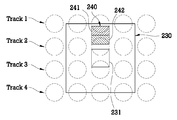
광분리부재(230)는 플레이트 형상이며 광분리부재(230)의 중앙에는 재생광 중 선택된 기록영역의 재생광이 통과될 수 있도록 홀(231)이 형성된다. 또한 홀(231)을 제외한 나머지 부분은 선택된 기록영역과 인접한 인접 기록영역에서 재생된 인접 재생광이 차폐되도록 차폐물질로 이루어진다. 또한 광분리부재(230)의 상면에는 차폐된 인접 재생광의 광정보를 검출하기 위한 제 2검출부(240)가 마련된다. The
제 2검출부(240)는 차폐된 인접 재생광 중 적어도 하나 이상의 인접 기록영역의 인접 재생광을 검출하며 인접 기록영역에서 재생된 인접 재생광을 검출할 수 있도록 제 1검출영역(241)과 제 2검출 영역(242)으로 이루어진다. 제 2검출부(240)의 광검출 영역에서 검출되는 인접 재생광의 광정보 즉 광량은 제어부(300)로 전달되어 트랙킹 위치가 판별되고, 조절부(310)에 의해 광학계(200)의 위치가 조절되어 트랙킹 위치를 조절할 수 있다. 조절부(310)는 리니어 엑츄에이터를 사용할 수 있다.The
이하에서는 트랙킹 위치와 광정보 검출에 대해 설명하기로 한다.Hereinafter, the tracking position and the optical information detection will be described.
도 3a는 광분리부재에 입사된 정확한 트랙킹 위치를 가지는 재생광과 제 2검출부를 나타낸 간략도이고, 도 3b는 저장매체의 회전으로 제 2검출부와 재생광의 위치가 어긋난 경우를 나타낸 간략도이다. FIG. 3A is a simplified diagram showing a regenerated light having a correct tracking position incident on the optical separation member and the second detector, and FIG. 3B is a simplified diagram showing a case where the positions of the second detector and the regenerated light are shifted due to the rotation of the storage medium.
도 3a에 도시된 바와 같이 광분리부재(230)에는 제 2검출부(240)가 포함된다. 제 2검출부(240)는 입사되는 입사 재생광 중 하나의 기록영역을 완전히 검출할 수 있는 크기에 해당하는 광검출 영역을 가진다. 이때 광검출 영역은 제 1검출영역(241)과 제 2검출영역(242)으로 나누어지며 광량을 감지할 수 있는 포토 다이오드로 구성될 수 있다.As shown in FIG. 3A, the
도 3a와 같이 트랙킹 위치가 정확할 경우 재생광 중 선택된 기록영역 주변의인접 기록영역에서 재생된 인접 재생광을 정확하게 검출할 수 있다. 이때 2분할된 광검출 영역 중 제 1검출영역(241)에서는 하나의 인접 기록영역에서 재생된 인접 재생광의 1/2광량이 검출되고, 나머지 제 2검출영역(242)에서는 상기 하나의 인접 기록영역에서 재생된 재생광의 1/2광량이 검출되어 제 1검출영역(241)과 제 2검출영역(242)이 같은 광량값을 가진다.When the tracking position is correct as shown in Fig. 3A, adjacent reproduction light reproduced in the adjacent recording area around the selected recording area among the reproduction light can be detected accurately. At this time, one-half light amount of the adjacent reproduction light reproduced in one adjacent recording area is detected in the
도 3b와 같이 저장매체(120)가 반시계 방향으로 회전하는 경우 저장매체(120)에 기록된 기록영역도 좌측으로 이동되므로 기록영역에서 재생된 재생광 또한 좌측으로 이동된다. 따라서 도 3b와 같이 광정보 저장매체(120)가 하나의 기록영역보다 짧은 거리로 회전했을 때 기록영역에서 재생된 인접 재생광의 일부와 이웃한 기록영역에서 재생된 인접 재생광의 일부가 제 2검출부(240)의 위치에 있는 것을 볼 수 있다. 이때 두 개의 인접 재생광의 간격으로 인하여 광검출 영역에서 검출되는 광량은 도 3a의 광량값보다 작은 값을 갖게 된다.When the
하지만 트랙킹 위치가 정확하기 때문에 제 2검출부(240)의 위치에 들어온 인접 재생광들의 일부가 정확히 반으로 분할되어 제 1검출영역(241)과 제 2검출영역(242)의 광량은 서로 같다. However, since the tracking position is correct, some of the adjacent regenerated light entering the position of the
도 4는 트랙킹 위치가 정확할 때 광정보 저장매체의 회전에 따라 변화되는 광검출량을 도시한 그래프이다. 도 4에 도시된 그래프의 X축은 시간, Y축은 광량을 나타낸다.4 is a graph showing the amount of light detection changed according to the rotation of the optical information storage medium when the tracking position is correct. In the graph shown in FIG. 4, the X axis represents time and the Y axis represents light quantity.
광정보 기록영역을 가진 저장매체(120)에 기준광을 입사하면 선택된 기록영역의 재생광과 그 주변에 인접 기록영역의 인접 재생광이 동시에 출사된다. 이후 제 2검출부(240)의 제 1검출영역(241)과 제 2검출영역(242)에서 인접 재생광의 광정보가 검출된다. 이때 제 1검출영역(241)과 제 2검출영역(242)에서 검출되는 광량값의 동일여부를 제어부(300)에서 판단하게 되며 동일하지 않을 경우 조절부(310) 를 제어하여 트랙킹 위치를 맞추게 된다. 또한 제 1검출영역(241)과 제 2검출영역(242)에서 검출되는 광량값이 동일한 경우 인접 재생광이 제 2검출부(240)에 정확히 위치하는 것인지 하나의 인접 재생광과 이웃한 인접 재생광 사이에 제 2검출부(240)가 위치하는 것인지를 광량값으로 판단하게 된다. When the reference light is incident on the
계속해서 트랙킹 위치가 맞춰지면 저장매체(120)는 회전하게 되고, 광량은 도 4의 그래프와 같이 변화된다. 제 1검출영역(241)과 제 2검출영역(242)에서 검출되는 광량은 일정한 간격으로 증가와 감속을 반복하게 된다. 즉 광검출영역에 하나의 기록영역에서 재생된 재생광이 정확히 들어올 때의 광량은 가장 최대값을 가지고, 회전하여 하나의 기록영역에서 재생된 재생광과 하나의 기록영역에 인접한 다른 기록영역에서 재생된 재생광 사이에 광검출영역이 위치할 때 광량은 가장 최소값을 가진다. If the tracking position is continuously adjusted, the
도 5a는 광분리부재에 입사된 트랙킹 정상 위치보다 위쪽에 위치한 재생광과 광검출부재를 나타낸 간략도이다. FIG. 5A is a simplified diagram showing the regenerated light and the light detecting member positioned above the tracking normal position incident on the light separating member.
도 5a에 도시된 바와 같이 트랙킹 위치가 정상 위치보다 위쪽에 위치하는 경우는 하나의 기록영역에서 재생된 재생광의 중앙부분이 제 1검출영역(241) 안에 위치되어 검출되는 광량이 크고, 상기 하나의 기록영역에서 재생된 재생광 일부와 다음 트랙에 위치한 기록영역에서 재생된 재생광의 일부분이 제 2검출영역(242) 안에 위치되어 검출되는 광량이 작은 것을 확인할 수 있다. 이러한 경우에는 제 1검출영역(241)과 제 2검출영역(242)에서 검출되는 광량의 크기가 같아야 트랙킹의 위치가 정확해지므로 조절부(310)를 제어하여 트랙킹 위치를 아래로 조절해야 한다.As shown in FIG. 5A, when the tracking position is located above the normal position, the central portion of the reproduced light reproduced in one recording area is located in the
또한 제 2검출영역(242)에서 검출한 광량이 제 1검출영역(241)에서 검출한 광량보다 큰 값을 가질 경우 트랙킹의 위치가 정상 위치가 아닌 아래쪽에 위치하는 경우이기 때문에 트랙킹 위치를 위로 조절해야 한다. In addition, if the amount of light detected in the
도 5b는 광분리부재에 입사된 재생광이 도 5a의 트랙킹 위치보다 더 위쪽에 위치하여 트랙킹 위치가 최대로 벗어난 경우를 나타낸 간략도이다. FIG. 5B is a simplified diagram illustrating a case in which the reproducing light incident on the optical separation member is located higher than the tracking position of FIG. 5A and thus the tracking position is deviated to the maximum.
도 5b에 도시된 바와 같이 검출하고자 하는 트랙이 도 5a보다 더 위쪽에 위치하여 제 1검출영역(241)에 기록영역에서 재생된 재생광의 일부가 위치하고, 제 2검출영역(242)에는 다른 트랙의 기록영역에서 재생된 재생광의 일부가 위치하여 검출되는 광량이 동일한 것을 확인할 수 있다. As shown in FIG. 5B, a track to be detected is located higher than FIG. 5A so that a part of the reproduced light reproduced in the recording area is located in the
이러한 경우 도 3a의 경우와 같이 제 1검출영역(241)과 제 2검출영역(242)에서 검출되는 광량값은 동일하나 트랙킹 위치를 확인하여 트랙 위치가 정상적일 때 제 1검출영역(241)과 제 2검출영역(242)에서 광량값이 동일한 경우와 트랙 위치의 변화로 제 1검출영역(241)과 제 2검출영역(242)의 광량값이 동일한 경우를 판별할 수 있다. In this case, as in the case of FIG. 3A, the light quantity values detected in the
도 6은 트랙위치가 정상위치에서 위쪽의 트랙으로 이동하는 경우 제 1검출영역과 제 2검출영역에서 검출하는 광량값을 도시한 그래프이다. 그래프의 X축은 시간을 의미하고, Y축은 광량값을 의미한다.FIG. 6 is a graph showing light quantity values detected in the first detection area and the second detection area when the track position moves from the normal position to the upper track. The X axis of the graph means time, and the Y axis means light quantity value.
선택된 기록영역에 기준광을 입사하면 선택된 기록영역의 재생광과 그 주변에 인접한 기록영역의 인접 재생광이 출사되고, 제 2검출부(240)의 제 1검출영역(241)과 제 2검출영역(242)에서 인접 재생광의 광정보를 검출하게 된다. 이때 제 1검출영역(241)과 제 2검출영역(242)에서 검출하는 광량값을 비교하여 현재의 트랙킹 위치를 판별한다. When the reference light is incident on the selected recording area, the reproduction light of the selected recording area and the adjacent reproduction light of the recording area adjacent thereto are emitted, and the
도 6에 도시한 바와 같이 제 1검출영역(241)과 제 2검출영역(242)에서 검출되는 광량값이 동일하면서 임의의 설정값과 일치하는 A지점은 트랙킹 위치가 정확한 것이므로 저장매체(120)가 회전하며 선택된 트랙의 광정보를 검출한다. 이후 선택된 트랙의 광정보 검출이 종료되면 다른 트랙의 광정보를 검출하기 위해 트랙의 위치가 이동되면서 검출되는 광량은 그래프와 같다. As shown in FIG. 6, since the tracking position is correct at the point A where the light quantity values detected in the
A지점 이후에 제 1검출영역(241)에서 검출되는 광량이 제 2검출영역(242)에서 검출되는 광량보다 증가되는데 이는 인접기록영역에서 재생된 인접 재생광의 중심이 제 1검출영역(241)으로 옮겨졌기 때문이다. After the point A, the amount of light detected in the
계속해서 인접 재생광이 더 위쪽으로 이동되면 인접 재생광의 중심은 제 1검출영역(241)을 벗어나 일부만 위치하게 되고, 다른 트랙의 인접 재생광 일부가 제 2검출영역(242)에 위치되어 제 1검출영역(241)과 제 2검출영역(242)에서 검출되는 광량은 동일해진다. 이는 5b의 상태이며 B지점을 나타낸다. Subsequently, when the adjacent reproduction light is further moved upward, only a portion of the center of the adjacent reproduction light is positioned outside the
이후 다른 트랙의 인접 재생광은 더 위쪽으로 이동되어 제 1검출영역(241)에서 검출되는 광량값보다 더 큰 광량값을 제 2검출영역(242)에서 검출하게 되고, 상기 다른 트랙의 인접 재생광이 더 위쪽으로 이동되어 광검출영역에 정확히 위치하게 되면 다시 A지점의 상태를 가진다. Subsequently, the adjacent reproduction light of the other track is moved upwards to detect a light amount value larger than the light amount value detected in the
도 7은 도 6의 제 1검출영역과 제 2검출영역에서 검출하는 광량값의 차이 변화를 나타낸 그래프이다. FIG. 7 is a graph illustrating a change in difference between light quantity values detected in the first and second detection areas of FIG. 6.
도 7에 도시한 바와 같이 A지점에서는 제 1검출영역(241)과 제 2검출영역(242)에 검출되는 광량값이 같기 때문에 차이값은 0이 된다. 이후 트랙킹 위치가 위로 이동하면 제 1검출영역(241)에 검출되는 광량값이 제 2검출영역(242)에서 검출되는 광량값보다 커지게 되어 그래프와 같이 상승한다. As shown in Fig. 7, the difference value becomes zero at the point A because the light quantity values detected in the
도 7에 도시된 그래프의 최대값은 이동된 인접 재생광의 중심이 제 1검출영역(241)의 중앙에 위치하는 것을 의미하며 인접 재생광의 중심이 제 1검출영역(241)의 중앙을 벗어나면서 그래프는 하강한다. 그래프의 최소값은 다른 트랙의 인접 재생광의 중심이 제 2검출영역(242)의 중앙에 위치하는 것을 의미한다. 이후 다른 트랙의 인접 재생광이 위로 이동하면 다시 A지점과 같은 상태가 된다.The maximum value of the graph shown in FIG. 7 means that the center of the moved adjacent reproduction light is located at the center of the
도 8는 4개의 광검출영역을 이용하여 인접 재생광의 광정보를 검출하는 제 2검출부를 나타낸 간략도이다. 8 is a simplified diagram showing a second detector that detects optical information of adjacent reproduction light by using four light detection areas.
도 8에 도시된 바와 같이 제 2검출부(240)가 4개의 광검출 영역을 이용하여 광정보를 검출한다. 즉 2분할된 제 2검출부(240)가 2개 구비된다.As shown in FIG. 8, the
이러한 제 1검출영역(241)과 제 2검출영역(242)에서 검출되는 광량의 차이 및 제 3검출영역(243)과 제 4검출영역(244)에서 검출되는 광량의 차이를 이용하여 트랙의 위치를 판별한다. The position of the track using the difference in the amount of light detected in the
예를 들어 제 1검출영역(241)과 제 2검출영역(242)에서 광이 검출되고, 제 3검출영역(243)과 제 4검출영역(244)에서 광이 검출되지 않을 때 이는 마지막 트랙을 의미할 수 있다. 또한 제 3검출영역(243)과 제 4검출영역(244)에서 광이 검출되고, 제 1검출영역(241)과 제 2검출영역(242)에서 광이 검출되지 않을 때 이는 첫번 째 트랙을 의미할 수 있다. 첫번째 트랙에서는 그 이전 트랙의 광량이 검출되지 않고, 마지막 트랙에서는 그 이후 트랙의 광량이 검출되지 않기 때문이다. For example, when light is detected in the
따라서 2분할된 제 2검출부(240)를 2개 이상 사용하면 1개를 사용할 때보다 트랙킹 위치 판별이 정확하고, 첫번째 트랙과 마지막 트랙의 구분도 가능하다.Therefore, when two or more divided
도 9는 본 발명의 실시예에 따른 광정보 재생장법을 설명하기 위한 흐름도이다.9 is a flowchart illustrating an optical information reproducing method according to an embodiment of the present invention.
먼저 광원(100)에서 방출된 광은 저장매체(120)로 입사된다(S100). 이후 저장매체(120)로 입사된 광에 의해 선택된 기록영역과 그 인접한 기록영역에서 재생광이 출사된다(S200). 출사된 재생광 중 선택된 기록영역의 재생광은 광분리부재(230)의 홀을 통과하여 제 1검출부(400)에 도달하고, 인접한 기록영역에서 재생된 인접 재생광은 광분리부재(230)로 입사되어 차폐된다(S300). 계속해서 광분리부재(230)에서 차폐된 인접 재생광은 광분리부재(230)에 포함된 제 2검출부(240)에 의해 광검출영역에서 광정보가 검출된다(S400). 검출된 광정보를 이용하여 현재의 트랙킹 상태를 분석한다(S500). 분석된 광정보에 따라 트랙킹 위치를 조절한다(S600). First, the light emitted from the
이상과 같은 본 발명에 따른 광정보 재생장치와 재생방법은 재생광을 선택된 기록영역의 재생광과 인접 재생광으로 분리하면서 동시에 인접 재생광의 광정보 검출하는 광분리부재를 사용하여 광정보 재생장치의 구조를 간단히 하고, 트랙킹 제 어에 필요한 재생광을 광분리부재에서 바로 검출하기 때문에 보다 정확한 광정보를 얻을 수 있다. The optical information reproducing apparatus and the reproducing method according to the present invention as described above use the optical information reproducing apparatus by using the optical separation member for separating the reproducing light into the reproducing light and the adjacent reproducing light of the selected recording area and simultaneously detecting the optical information of the adjacent reproducing light. The structure is simplified, and more accurate optical information can be obtained because the regenerated light required for tracking control is detected directly by the optical separation member.
Claims (8)
Priority Applications (7)
| Application Number | Priority Date | Filing Date | Title |
|---|---|---|---|
| KR1020060092892A KR100825640B1 (en) | 2006-09-25 | 2006-09-25 | Optical information playback device and playback method |
| EP07005295A EP1843333B1 (en) | 2006-04-06 | 2007-03-14 | Optical information reproducing apparatus and optical information reproducing method using the same |
| AT07005295T ATE440362T1 (en) | 2006-04-06 | 2007-03-14 | OPTICAL INFORMATION REPRODUCTION DEVICE AND OPTICAL INFORMATION REPRODUCTION METHOD THEREFROM |
| DE602007001995T DE602007001995D1 (en) | 2006-04-06 | 2007-03-14 | Optical information reproducing apparatus and optical information reproducing method therewith |
| TW096109519A TWI342561B (en) | 2006-04-06 | 2007-03-20 | Optical information reproducing apparatus and optical information reproducing method using the same |
| US11/688,492 US8634282B2 (en) | 2006-04-06 | 2007-03-20 | Apparatus and method for providing a tracking servo control when reproducing optical information |
| JP2007083129A JP4680224B2 (en) | 2006-04-06 | 2007-03-27 | Optical information reproducing apparatus and optical information reproducing method |
Applications Claiming Priority (1)
| Application Number | Priority Date | Filing Date | Title |
|---|---|---|---|
| KR1020060092892A KR100825640B1 (en) | 2006-09-25 | 2006-09-25 | Optical information playback device and playback method |
Publications (2)
| Publication Number | Publication Date |
|---|---|
| KR20080027598A KR20080027598A (en) | 2008-03-28 |
| KR100825640B1 true KR100825640B1 (en) | 2008-04-25 |
Family
ID=39414462
Family Applications (1)
| Application Number | Title | Priority Date | Filing Date |
|---|---|---|---|
| KR1020060092892A Expired - Fee Related KR100825640B1 (en) | 2006-04-06 | 2006-09-25 | Optical information playback device and playback method |
Country Status (1)
| Country | Link |
|---|---|
| KR (1) | KR100825640B1 (en) |
Citations (3)
| Publication number | Priority date | Publication date | Assignee | Title |
|---|---|---|---|---|
| JPH10149564A (en) * | 1996-11-15 | 1998-06-02 | Teac Corp | Optical pickup device and tracking error detection method |
| KR20020059666A (en) * | 1999-11-09 | 2002-07-13 | 모리시타 요이찌 | Photoelectronic device |
| KR20040035111A (en) * | 2002-10-18 | 2004-04-29 | 삼성전자주식회사 | Optical pick-up cutting off optical noise and optical recording and/of reproducing apparatus |
-
2006
- 2006-09-25 KR KR1020060092892A patent/KR100825640B1/en not_active Expired - Fee Related
Patent Citations (3)
| Publication number | Priority date | Publication date | Assignee | Title |
|---|---|---|---|---|
| JPH10149564A (en) * | 1996-11-15 | 1998-06-02 | Teac Corp | Optical pickup device and tracking error detection method |
| KR20020059666A (en) * | 1999-11-09 | 2002-07-13 | 모리시타 요이찌 | Photoelectronic device |
| KR20040035111A (en) * | 2002-10-18 | 2004-04-29 | 삼성전자주식회사 | Optical pick-up cutting off optical noise and optical recording and/of reproducing apparatus |
Also Published As
| Publication number | Publication date |
|---|---|
| KR20080027598A (en) | 2008-03-28 |
Similar Documents
| Publication | Publication Date | Title |
|---|---|---|
| JP2002183987A (en) | Optical information recording device, reproducing device and optical head device | |
| KR100555916B1 (en) | Recording and playback device for focus servo control of holographic ROM system | |
| US7903526B2 (en) | Recording/reproducing apparatus, method of reproducing data, and servo controlling method | |
| KR100825640B1 (en) | Optical information playback device and playback method | |
| CN100582965C (en) | Optical information reproducing apparatus and optical information reproducing method using the same | |
| US20070041302A1 (en) | Information recording apparatus, and information recording/reproducing apparatus | |
| US8634282B2 (en) | Apparatus and method for providing a tracking servo control when reproducing optical information | |
| JP4680225B2 (en) | Optical information processing apparatus and optical information processing method | |
| US20080137512A1 (en) | Holographic information recording/reproducing apparatus and method for seeking books in the same | |
| KR100767934B1 (en) | Tracking error detection method and optical information reproducing apparatus using same | |
| EP1804241A2 (en) | Optical pickup, optical disc apparatus, and radial tilt detection method | |
| KR100624264B1 (en) | Angle / Tracking Servo Control for Holographic Playback System | |
| KR100579614B1 (en) | Track Servo Control for Holographic ROM System | |
| JP3478483B2 (en) | Optical pickup device | |
| KR100555921B1 (en) | Track Servo Control for Holographic Playback System | |
| KR100681618B1 (en) | Focusing device and method for holographic disc | |
| KR100692574B1 (en) | Diffraction element and optical pickup device comprising same | |
| US7983134B2 (en) | Method and apparatus for recording/reproducing data on/from a recording medium | |
| KR100624265B1 (en) | Wobble processed holographic ROM disk and tracking and focusing servo device in holographic ROM player | |
| KR100676872B1 (en) | Optical information position detecting method, optical information detecting method, optical information detector and optical information processing method | |
| KR100579634B1 (en) | Angle Servo Control for Holographic Playback System | |
| WO2004086388A1 (en) | Optical record carrier and optical scanning device | |
| JPH0279228A (en) | Optical pickup device | |
| KR20070103875A (en) | Method and apparatus for replaying data | |
| KR20100085281A (en) | The method for recording/reproducing of the recording medium and the apparatus the same |
Legal Events
| Date | Code | Title | Description |
|---|---|---|---|
| A201 | Request for examination | ||
| PA0109 | Patent application |
St.27 status event code: A-0-1-A10-A12-nap-PA0109 |
|
| PA0201 | Request for examination |
St.27 status event code: A-1-2-D10-D11-exm-PA0201 |
|
| D13-X000 | Search requested |
St.27 status event code: A-1-2-D10-D13-srh-X000 |
|
| D14-X000 | Search report completed |
St.27 status event code: A-1-2-D10-D14-srh-X000 |
|
| E902 | Notification of reason for refusal | ||
| PE0902 | Notice of grounds for rejection |
St.27 status event code: A-1-2-D10-D21-exm-PE0902 |
|
| P11-X000 | Amendment of application requested |
St.27 status event code: A-2-2-P10-P11-nap-X000 |
|
| P13-X000 | Application amended |
St.27 status event code: A-2-2-P10-P13-nap-X000 |
|
| PG1501 | Laying open of application |
St.27 status event code: A-1-1-Q10-Q12-nap-PG1501 |
|
| E701 | Decision to grant or registration of patent right | ||
| PE0701 | Decision of registration |
St.27 status event code: A-1-2-D10-D22-exm-PE0701 |
|
| GRNT | Written decision to grant | ||
| PR0701 | Registration of establishment |
St.27 status event code: A-2-4-F10-F11-exm-PR0701 |
|
| PR1002 | Payment of registration fee |
St.27 status event code: A-2-2-U10-U11-oth-PR1002 Fee payment year number: 1 |
|
| PG1601 | Publication of registration |
St.27 status event code: A-4-4-Q10-Q13-nap-PG1601 |
|
| R18-X000 | Changes to party contact information recorded |
St.27 status event code: A-5-5-R10-R18-oth-X000 |
|
| FPAY | Annual fee payment |
Payment date: 20110401 Year of fee payment: 4 |
|
| PR1001 | Payment of annual fee |
St.27 status event code: A-4-4-U10-U11-oth-PR1001 Fee payment year number: 4 |
|
| PN2301 | Change of applicant |
St.27 status event code: A-5-5-R10-R11-asn-PN2301 |
|
| PN2301 | Change of applicant |
St.27 status event code: A-5-5-R10-R14-asn-PN2301 |
|
| FPAY | Annual fee payment |
Payment date: 20120403 Year of fee payment: 5 |
|
| PR1001 | Payment of annual fee |
St.27 status event code: A-4-4-U10-U11-oth-PR1001 Fee payment year number: 5 |
|
| P22-X000 | Classification modified |
St.27 status event code: A-4-4-P10-P22-nap-X000 |
|
| FPAY | Annual fee payment |
Payment date: 20130403 Year of fee payment: 6 |
|
| PR1001 | Payment of annual fee |
St.27 status event code: A-4-4-U10-U11-oth-PR1001 Fee payment year number: 6 |
|
| PN2301 | Change of applicant |
St.27 status event code: A-5-5-R10-R13-asn-PN2301 St.27 status event code: A-5-5-R10-R11-asn-PN2301 |
|
| FPAY | Annual fee payment |
Payment date: 20140331 Year of fee payment: 7 |
|
| PR1001 | Payment of annual fee |
St.27 status event code: A-4-4-U10-U11-oth-PR1001 Fee payment year number: 7 |
|
| R18-X000 | Changes to party contact information recorded |
St.27 status event code: A-5-5-R10-R18-oth-X000 |
|
| LAPS | Lapse due to unpaid annual fee | ||
| PC1903 | Unpaid annual fee |
St.27 status event code: A-4-4-U10-U13-oth-PC1903 Not in force date: 20150422 Payment event data comment text: Termination Category : DEFAULT_OF_REGISTRATION_FEE |
|
| R17-X000 | Change to representative recorded |
St.27 status event code: A-5-5-R10-R17-oth-X000 |
|
| PC1903 | Unpaid annual fee |
St.27 status event code: N-4-6-H10-H13-oth-PC1903 Ip right cessation event data comment text: Termination Category : DEFAULT_OF_REGISTRATION_FEE Not in force date: 20150422 |
|
| P22-X000 | Classification modified |
St.27 status event code: A-4-4-P10-P22-nap-X000 |
|
| R18-X000 | Changes to party contact information recorded |
St.27 status event code: A-5-5-R10-R18-oth-X000 |
|
| R18-X000 | Changes to party contact information recorded |
St.27 status event code: A-5-5-R10-R18-oth-X000 |
|
| PN2301 | Change of applicant |
St.27 status event code: A-5-5-R10-R13-asn-PN2301 St.27 status event code: A-5-5-R10-R11-asn-PN2301 |
|
| PN2301 | Change of applicant |
St.27 status event code: A-5-5-R10-R13-asn-PN2301 St.27 status event code: A-5-5-R10-R11-asn-PN2301 |