KR100822466B1 - An image processing apparatus, an image forming apparatus, and a recording medium recording a program - Google Patents
An image processing apparatus, an image forming apparatus, and a recording medium recording a program Download PDFInfo
- Publication number
- KR100822466B1 KR100822466B1 KR1020067013156A KR20067013156A KR100822466B1 KR 100822466 B1 KR100822466 B1 KR 100822466B1 KR 1020067013156 A KR1020067013156 A KR 1020067013156A KR 20067013156 A KR20067013156 A KR 20067013156A KR 100822466 B1 KR100822466 B1 KR 100822466B1
- Authority
- KR
- South Korea
- Prior art keywords
- value
- threshold
- level
- image
- image data
- Prior art date
- Legal status (The legal status is an assumption and is not a legal conclusion. Google has not performed a legal analysis and makes no representation as to the accuracy of the status listed.)
- Expired - Fee Related
Links
Images


Classifications
-
- H—ELECTRICITY
- H04—ELECTRIC COMMUNICATION TECHNIQUE
- H04N—PICTORIAL COMMUNICATION, e.g. TELEVISION
- H04N1/00—Scanning, transmission or reproduction of documents or the like, e.g. facsimile transmission; Details thereof
- H04N1/40—Picture signal circuits
- H04N1/405—Halftoning, i.e. converting the picture signal of a continuous-tone original into a corresponding signal showing only two levels
- H04N1/4051—Halftoning, i.e. converting the picture signal of a continuous-tone original into a corresponding signal showing only two levels producing a dispersed dots halftone pattern, the dots having substantially the same size
- H04N1/4052—Halftoning, i.e. converting the picture signal of a continuous-tone original into a corresponding signal showing only two levels producing a dispersed dots halftone pattern, the dots having substantially the same size by error diffusion, i.e. transferring the binarising error to neighbouring dot decisions
-
- B—PERFORMING OPERATIONS; TRANSPORTING
- B41—PRINTING; LINING MACHINES; TYPEWRITERS; STAMPS
- B41J—TYPEWRITERS; SELECTIVE PRINTING MECHANISMS, i.e. MECHANISMS PRINTING OTHERWISE THAN FROM A FORME; CORRECTION OF TYPOGRAPHICAL ERRORS
- B41J2/00—Typewriters or selective printing mechanisms characterised by the printing or marking process for which they are designed
- B41J2/52—Arrangement for printing a discrete number of tones, not covered by group B41J2/205, e.g. applicable to two or more kinds of printing or marking process
Landscapes
- Engineering & Computer Science (AREA)
- Multimedia (AREA)
- Signal Processing (AREA)
- Facsimile Image Signal Circuits (AREA)
- Image Processing (AREA)
Abstract
멀티 레벨(M 레벨) 화상 데이터를, 멀티 레벨 에러 확산 처리(multi-level error-diffusion process) 또는 멀티 레벨 평균 에러 최소법(minimum-average multi-level error method)을 사용하여, N 값으로(여기서 M > N > 1) 양자화하는 화상 처리 장치가 제공된다.Multi-level (M level) image data can be converted to an N value, where a multi-level error-diffusion process or a minimum-average multi-level error method is used. M> N> 1) An image processing apparatus for quantizing is provided.
상기 화상 처리 장치는, 보정 데이터를 출력하는 수단; 양자화 역치를 설정하는 수단; 상기 보정 데이터와 상기 양자화 역치를 비교하여 N 레벨 화상 데이터를 출력하는 수단; 및 상기 N 레벨 화상 데이터를 생성할 때 발생하는 에러를 산출하는 수단;을 포함한다.The image processing apparatus includes: means for outputting correction data; Means for setting a quantization threshold; Means for comparing the correction data with the quantization threshold and outputting N level image data; And means for calculating an error occurring when generating the N level image data.
화상 처리 장치, 화상 형성 장치, 멀티 레벨 화상 데이터, 에러 확산 처리, 평균 에러 최소법 Image processing apparatus, image forming apparatus, multi-level image data, error diffusion processing, average error minimum method
Description
본 발명은 일반적으로 화상 처리 장치, 화상 형성 장치 및 프로그램을 기록한 기록매체에 관한 것이다.The present invention relates generally to an image processing apparatus, an image forming apparatus and a recording medium on which a program is recorded.
스캐너나 디지털 카메라 등의 입력장치로 판독된 멀티 값(multi-value) 화상 데이터를 프린터나 디스플레이 등의 출력장치에 출력하는 화상 입출력 시스템에 있어서, 입력장치로 판독된 멀티 레벨(multi-level)(예: 8 비트 정밀도의 경우 256 톤(tones)) 화상 데이터를 출력장치가 출력 가능한 다수의 톤과 의사 표현하는 연속적인 톤(pseudo-representing successive tones)을 갖는 화상 데이터로 변환하는 방법으로서 의사 중간 톤 처리(pseudo-intermediate tone process)가 알려져 있다.In an image input / output system for outputting multi-value image data read by an input device such as a scanner or a digital camera to an output device such as a printer or a display, the multi-level ( Example: A method of converting 256 tones image data into image data having pseudo-representing successive tones that are output by the output device and pseudo-representing successive tones. A pseudo-intermediate tone process is known.
이러한 의사 중간 톤 처리로서, 출력장치가 도트(dot)의 ON/OFF의 2 레벨만을 표현할 수밖에 없는 경우에는 2 레벨 처리가 종래부터 행해지고 있다. 이러한 2 레벨 처리에는 해상도와 톤이 우수한 것으로 에러 확산 처리(error-diffusion process)와 평균 에러 최소법(minimum-average error method)이 있다. 이러한 에러 확산법과 평균 에러 최소법은 에러의 확산 작업을 행하는 시기에 있어 차이가 있을 뿐, 논리적으로 서로 등가이다.As such pseudo intermediate tone processing, when the output device can only express two levels of ON / OFF of a dot, two-level processing has conventionally been performed. These two-level processes are excellent in resolution and tone, including an error-diffusion process and a minimum-average error method. The error spreading method and the mean error minimizing method differ only in the timing of spreading the error, and are logically equivalent to each other.
또한, 이와 같은 에러 확산 처리를 2 레벨뿐만 아니라 3 레벨 이상의 톤 수에 적용한 것으로, 멀티 레벨 에러 확산 처리가 있다. 이러한 멀티 레벨 에러 확산 처리도 상기 2 레벨 에러 확산 처리와 마찬가지로 해상도와 톤이 우수하다.In addition, such error diffusion processing is applied not only to two levels but also to three or more levels of tones, and there is a multilevel error diffusion processing. This multi-level error spreading process has excellent resolution and tone as well as the two-level error spreading process.
한편, 출력장치에 있어서 3 레벨 이상의 톤 수를 확보하기 위해 여러 가지 방식이 알려져 있다. 예를 들어, 잉크방울을 토출하여 화상을 형성하는 잉크젯 기록방식의 화상 형성 장치에 있어서는, 토출되는 잉크방울을 제어하여 도트 지름을 대, 중, 소로 변화시키는 방식; 도트를 오버프린팅(overprinting)하는 방식; 농도가 다른 기록 액체잉크 또는 농담(濃淡)(variable-density) 잉크를 사용하는 방식 등을 이용하여 3 레벨 이상의 톤 수를 재현하고 있다. 또한, 엷은 잉크의 농도는 진한 잉크를 1/6 내지 1/2로 희석하는 것이 일반적이다.On the other hand, various methods are known in order to secure three or more levels of tones in the output device. For example, an ink jet recording method image forming apparatus which ejects ink droplets to form an image, comprising: a method of controlling the ejected ink droplets to change the dot diameter to large, medium, or small; Overprinting the dots; Tone counts of three or more levels are reproduced by using a recording liquid ink having a different density or a method using variable-density inks. In addition, the density of the light ink is generally diluted to 1/6 to 1/2 of the dark ink.
또한, 전자사진 방식의 화상 형성 장치에서는, 하나의 도트가 형성하는 노광량을 제어하도록 노광 기록에 있어 펄스 폭을 분할하는 방식 및 도트 지름을 변조시키도록 노광으로 사용되는 레이저광의 강도를 조절하는 방식 등을 이용하고 있다.Further, in an electrophotographic image forming apparatus, a method of dividing a pulse width in exposure recording to control an exposure amount formed by one dot, a method of adjusting the intensity of a laser beam used for exposure to modulate the dot diameter, and the like. Is using.
최근, 전술한 에러 확산 처리의 하나의 문제점으로서, 도트 생성의 지연으로 인해 백지부(white-background portion)(톤 값 0) 또는 짙은 농도부(solidly-shaded portion)(톤 값 255) 부근에 도 10에 도시된 바와 같이 의사 윤곽(pseudo-contour) R이 발생하는 것이 알려져 있다.Recently, as one of the problems of the above-described error diffusion processing, due to the delay of dot generation, it has been found in the vicinity of the white-background portion (tone value 0) or the solidly-shaded portion (tone value 255). It is known that pseudo-contour R occurs as shown at 10.
일본특허공개공보 07-111591호(이하 "특허문헌 1" 이라 함)에 기재되어 있는 바와 같이, 예를 들어 농도에 따라 역치(threshold value)을 변화시키고, 2 레벨 에러 확산 처리에 있어서 하이라이트(highlighted)부에서 도트 생성의 지연 또는 짙은 농도부에서 홀(hole) 생성의 지연을 없애는 것이 알려져 있다.As described in Japanese Patent Application Laid-Open No. 07-111591 (hereinafter referred to as "
또한, 멀티 레벨 에러 확산 처리에 있어서는, N 레벨 양자화(quantization) 출력이 변화하여, 일부분에서 도트 생성의 지연으로 인해 화상 품질의 저하가 문제된다.In addition, in the multi-level error diffusion processing, the N-level quantization output changes, which causes a problem of deterioration in image quality due to delays in dot generation.
일본특허공개공보 2003-219161호(이하 "특허문헌 2" 이라 함)에 기재되어 있는 바와 같이, M 톤 화상의 각각의 픽셀에 대해 N-1 개의 기준 역치를 이용하는 에러 확산 처리에 따라 N 값(여기서 M > N)으로 양자화하는 양자화 수단을 포함하는 화상 형성 장치가 알려져 있는데, M 톤은 N-1 개의 구간으로 분할되고 각각의 구간에 있어서 역치는 해당 픽셀의 입력 톤 값에 따라 달라진다.As described in Japanese Patent Laid-Open No. 2003-219161 (hereinafter referred to as "
또한, 일본특허공개공보 2004-112089호(이하 "특허문헌 3" 이라 함)에 기재되어 있는 바와 같이, 톤의 구간이 불균등한 경우에 있어서 출력장치가 갖는 톤 근처(양자화 레벨)에서 농도가 출력될 때 의사 윤곽이 발생한다는 문제점을 해결하기 위해, 해당 픽셀의 멀티 레벨 화상 데이터에 주변의 이미 양자화가 끝난 픽셀로부터 확산되는 에러를 더한 보정 데이터를 출력하는 수단; 상기 픽셀의 멀티 레벨 화상 데이터에 근거하여 양자화 역치를 설정하는 수단; 보정 데이터와 양자화 역치를 비교하여 N 레벨 화상 데이터를 출력하는 수단; 및 상기 N 레벨 화상 데이터를 생성할 때 발생하는 에러를 산출하는 수단을 포함하는 구성이 알려져 있다. 상기와 같은 구성은 양자화 값을 1, 2, ..., a, b, ..., N 으로 하고, 양자화 값의 톤을 O1, O2, ..., Oa, Ob, ..., ON 으로 가정할 때, 입력값의 구간 Oa ~ Ob 에서 i 번째 역치 Thi(i는 0 < i ≤ N-1 의 정수)는, 입력 농도 값을 In으로 했을 때, Thi = Ki × In + (Oa + Ob) * (1 - Ki) / 2 - (Oa - Oi) 에 근거하여 설정된 값이 되는데, 여기서 Ki는 0 이상의 실수이며, i는 0 < i ≤ N-1 의 정수이다.In addition, as described in Japanese Patent Application Laid-Open No. 2004-112089 (hereinafter referred to as "
그러나, 특허문헌 1은 도트 생성의 지연으로 인한 화상 일그러짐의 문제를 해결하고 있지만, 이는 단일 화상 또는 단일 에러 확산 처리에서의 출력 결과에 착안한 것이므로, 다수의 에러 확산 처리되는 화상을 인접시키고 결합시키는 경우 또는 단일의 화상을 다수의 영역으로 분할하여 각각의 영역을 에러 확산 처리한 경우에 발생하는 의사 윤곽(도 11에서 R로 나타내는 부분)의 문제에 대해서는 기재되어 있지 않다.However, although
따라서, 도 12에서 R로 나타내는 부분처럼 도트 생성의 지연을 개선할 수 있어도, 화상을 인접시키는 경우에는 너무 빠른 도트 생성으로 인해 도 13에서 R로 나타내는 부분처럼 의사 윤곽이 발생할 수 있다는 문제점이 있다.Therefore, even if the delay of dot generation can be improved as shown by R in FIG. 12, there is a problem that pseudo contours may occur as shown in R in FIG. 13 due to too fast dot generation when the images are adjacent.
단일 화상의 경우, 화상 에지(edge)부에 있어서 도트 생성의 지연 또는 선행(leading)은 육안(肉眼)으로 볼 때 불편함을 초래하지 않는 것이 일반적이다. 그러나, 이와 같은 화상을 인접시키고 결합시키는 것은 전술한 바와 같이 경계 부분을 눈에 띄게 하고, 작은 불연속성에 의해서도 시각적으로 불편함을 초래하는데, 특히 경계 부분의 양쪽 모두가 동일한 톤인 경우에 더욱 그러하다.In the case of a single image, it is common that the delay or leading of dot generation in the image edge portion does not cause inconvenience to the naked eye. However, adjoining and combining such images, as described above, makes the border portion noticeable and causes visual discomfort even with small discontinuities, especially when both border portions are the same tone.
또한, 에러 확산 처리에 사용되는 메모리량을 억제하기 위한 것 등의 이유로 인해, 단일 화상을 다수의 작은 영역으로 분할하여 각각의 화상 단위에 대해 에러 확산 처리를 행하는 경우가 있다. 이러한 경우, 처리 경계에 있어 동일한 톤이 계속되는 경향이 있어 도트 생성의 지연 또는 선행이 문제되기 쉽다.Further, for the reason of suppressing the amount of memory used for the error diffusion process, the error diffusion process may be performed for each image unit by dividing a single image into a plurality of small areas. In such a case, the same tone tends to continue at the processing boundary, so the delay or precedence of dot generation tends to be a problem.
이와 같은 에러 확산 처리 단위의 인접 경계에 있어서 도트 생성의 지연이 있는 경우에는 빈 간격이 생기는 것과 같은 줄무늬 형태(도 11에서 R로 나타내는 부분)가 나타나고, 도트 생성의 선행이 있는 경우에는 농도가 진한 줄무늬 형태(도 13에서 R로 나타내는 부분)가 나타난다는 문제점이 있다.When there is a delay of dot generation at the adjacent boundary of such an error diffusion processing unit, a stripe form (a portion indicated by R in FIG. 11) such as an empty gap appears, and when the precedence of dot generation occurs, the density is high. There is a problem in that a stripe form (part indicated by R in FIG. 13) appears.
본 발명은 전술한 문제점을 해결하기 위해 제안된 것으로, 에러 확산 처리 유닛이 인접하는 경계에서 발생하는 줄무늬 형태의 의사 윤곽을 방지함으로써 처리 화상의 품질 저하를 억제하고, 처리 단위를 다수의 작은 영역으로 분할할 수 있게 함으로써 메모리 사용량의 감소를 도모하는 화상 처리 장치, 화상 형성 장치, 및 프로그램을 기록한 기록매체를 제공한다.SUMMARY OF THE INVENTION The present invention has been proposed to solve the above-mentioned problem, and the error diffusion processing unit suppresses the stripe-like pseudo contour occurring at adjacent borders, thereby suppressing deterioration of the quality of the processed image, and processing the processing unit into a plurality of small areas. An image processing apparatus, an image forming apparatus, and a recording medium on which a program is recorded are provided to reduce the amount of memory used.
본 발명의 특징 및 장점은 첨부 도면을 참조하여 아래의 상세한 설명으로부터 명확하게 될 것이다. The features and advantages of the present invention will become apparent from the following detailed description with reference to the accompanying drawings.
또한, 본 발명의 다른 특징 및 장점은 물론, 본 발명의 목적은 본 명세서에 당업자가 실시할 수 있도록 상세히 기재되어 있는 화상 처리 장치, 화상 형성 장치, 및 프로그램을 기록한 기록매체로부터 실현될 것이다.In addition, as well as other features and advantages of the present invention, the object of the present invention will be realized from an image processing apparatus, an image forming apparatus, and a recording medium having recorded thereon the program described in detail for those skilled in the art to practice.
본 발명의 목적에 따른 상기 및 다른 장점을 달성하기 위해, 본 발명이 제공하는 것은 다음과 같다.In order to achieve the above and other advantages according to the object of the present invention, the present invention provides the following.
본 발명의 일 특징에 의하면, According to one feature of the invention,
멀티 레벨(M 레벨) 화상 데이터를, 멀티 레벨 에러 확산 처리(multi-level error-diffusion process) 또는 멀티 레벨 평균 에러 최소법(minimum-average multi-level error method)을 사용하여, N 값으로(여기서 M > N > 1) 양자화하는 화상 처리 장치에 있어서, 해당 픽셀의 멀티 레벨 화상 데이터에 주변의 이미 양자화가 끝난 픽셀로부터 확산되는 에러를 더한 보정 데이터를 출력하는 수단; 상기 해당 픽셀의 멀티 레벨 화상 데이터에 근거하여 양자화 역치를 설정하는 수단; 상기 보정 데이터와 상기 양자화 역치를 비교하여 N 레벨 화상 데이터를 출력하는 수단; 및 상기 N 레벨 화상 데이터를 생성할 때 발생하는 에러를 산출하는 수단;을 포함하며, 양자화 값을 0, 1, 2, ..., N-1 이라 하고, 양자화 값의 톤(tone)을 V0, V1, V2, ..., VN-1 이라 할 때, 적어도 하나의 입력값의 구간 Va ~ Va +1 (0 ≤ a < N-1) 에서 적어도 하나의 역치 Tha + 1는, 입력 톤 값이 υ인 경우, 다음의 [수식 1]에 근거하여 설정되는 것을 특징으로 하는 화상 처리 장치가 제공된다.Multi-level (M level) image data can be converted to an N value, where a multi-level error-diffusion process or a minimum-average multi-level error method is used. M>N> 1) A quantization image processing apparatus comprising: means for outputting correction data obtained by adding multi-level image data of a corresponding pixel to an error diffused from neighboring already quantized pixels; Means for setting a quantization threshold based on the multilevel image data of the corresponding pixel; Means for comparing the correction data with the quantization threshold and outputting N level image data; And means for calculating an error occurring when generating the N level image data, wherein the quantization values are 0, 1, 2, ..., N-1, and the tone of the quantization value is V0. , V1, V2, ..., VN-1, at least one threshold Th a + 1 in the interval V a ~ V a +1 (0 ≤ a <N-1) of at least one input value, When the input tone value is ν, an image processing apparatus is set based on the following [Equation 1].
[수식 1][Equation 1]
![]()
![]()
본 발명의 다른 특징에 의하면,According to another feature of the invention,
입력되는 멀티 레벨(M 레벨) 화상 데이터를, 멀티 레벨 에러 확산 처리 또는 멀티 레벨 평균 에러 최소법을 사용하여, N 값으로(여기서 M > N > 1) 양자화하고, 각각의 상기 N 값에 대응하는 도트(dots)를 사용하여 화상을 형성하는 화상 형성 장치에 있어서, 해당 픽셀의 멀티 레벨 화상 데이터에 주변의 이미 양자화가 끝난 픽셀로부터 확산되는 에러를 더한 보정 데이터를 출력하는 수단; 상기 해당 픽셀의 멀티 레벨 화상 데이터에 근거하여 양자화 역치를 설정하는 수단; 상기 보정 데이터와 상기 양자화 역치를 비교하여 N 레벨 화상 데이터를 출력하는 수단; 및 상기 N 레벨 화상 데이터를 생성할 때 발생하는 에러를 산출하는 수단;을 포함하며, 양자화 값을 0, 1, 2, ..., N-1 이라 하고, 양자화 값의 톤을 V0, V1, V2, ..., VN-1 이라 할 때, 적어도 하나의 입력값의 구간 Va ~ Va +1 (0 ≤ a < N-1) 에서 적어도 하나의 역치 Tha + 1는, 입력 톤 값이 υ인 경우, 다음의 [수식 1]에 근거하여 설정되는 것을 특징으로 하는 화상 형성 장치가 제공된다.The input multi-level (M level) image data is quantized to an N value (where M > N > 1) using a multi-level error diffusion process or a multi-level average error minimization method, and corresponds to each of the above N values. An image forming apparatus for forming an image using dots, comprising: means for outputting correction data obtained by adding multi-level image data of a corresponding pixel to an error diffused from neighboring already quantized pixels; Means for setting a quantization threshold based on the multilevel image data of the corresponding pixel; Means for comparing the correction data with the quantization threshold and outputting N level image data; And means for calculating an error occurring when generating the N level image data, wherein the quantization values are 0, 1, 2, ..., N-1, and the tones of the quantization values are V0, V1, In the case of V2, ..., VN-1, at least one threshold Th a + 1 in the interval V a to V a +1 (0 ≤ a <N-1) of at least one input value is an input tone value. In the case of ν, an image forming apparatus is provided based on the following [Equation 1].
[수식 1][Equation 1]
![]()
![]()
본 발명의 다른 특징에 의하면,According to another feature of the invention,
멀티 레벨(M 레벨) 화상 데이터를, 멀티 레벨 에러 확산 처리 또는 멀티 레벨 평균 에러 최소법을 사용하여, N 값으로(여기서 M > N > 1) 양자화하는 처리를 컴퓨터가 실행하도록 하는 프로그램을 기록한 기록매체에 있어서,Recorded recording of a program that causes a computer to execute a process of quantizing multilevel (M level) image data to an N value (where M > N > 1) using a multilevel error diffusion process or a multilevel average error minimization method In the medium,
해당 픽셀의 멀티 레벨 화상 데이터에 주변의 이미 양자화가 끝난 픽셀로부터 확산되는 에러를 더한 보정 데이터를 출력하는 단계의 코드;Code for outputting correction data obtained by adding multi-level image data of a corresponding pixel to an error diffused from neighboring quantized pixels;
상기 해당 픽셀의 멀티 레벨 화상 데이터에 근거하여 양자화 역치를 설정하는 단계의 코드;Code for setting a quantization threshold based on the multi-level image data of the corresponding pixel;
상기 보정 데이터와 상기 양자화 역치를 비교하여 N 레벨 화상 데이터를 출력하는 단계의 코드; 및Code for outputting N level image data by comparing the correction data with the quantization threshold; And
상기 N 레벨 화상 데이터를 생성할 때 발생하는 에러를 산출하는 단계의 코드;를 포함하며,A code of calculating an error occurring when generating the N level image data;
양자화 값을 0, 1, 2, ..., N-1 이라 하고, 양자화 값의 톤을 V0, V1, V2, ..., VN-1 이라 할 때, 적어도 하나의 입력값의 구간 Va ~ Va+1 (0 ≤ a < N-1) 에서 적어도 하나의 역치 Tha+1는, 입력 톤 값이 υ인 경우, 다음의 [수식 1]에 근거하여 설정되는 것을 특징으로 하는 프로그램을 기록한 기록매체가 제공된다.When the quantization value is 0, 1, 2, ..., N-1, and the tone of the quantization value is V0, V1, V2, ..., VN-1, the interval V a of at least one input value At least one threshold Th a + 1 at V a + 1 (0 ≦ a <N−1) is set based on
[수식 1][Equation 1]
![]()
![]()
도 1은 본 발명을 적용한 화상 처리 장치를 포함하는 화상 입출력 시스템의 블록 설명도이다.1 is a block diagram of an image input / output system including an image processing apparatus to which the present invention is applied.
도 2는 상기 화상 처리 장치의 본 발명에 관계되는 화상 처리부의 기능 블럭도이다.2 is a functional block diagram of an image processing unit according to the present invention of the image processing apparatus.
도 3은 본 발명을 적용한 화상 형성 장치에서 출력되는 3 레벨의 도트를 설명하는 설명도이다.3 is an explanatory diagram illustrating dots of three levels output from the image forming apparatus to which the present invention is applied.
도 4는 상기 화상 처리부의 에러 확산부에 사용되는 에러 계수의 일 예를 설명하는 설명도이다.4 is an explanatory diagram for explaining an example of an error coefficient used in the error diffusion section of the image processing section.
도 5는 상기 화상 형성 장치의 기구부의 일 예를 설명하는 측면도이다.5 is a side view illustrating an example of a mechanism part of the image forming apparatus.
도 6은 상기 화상 형성 장치의 기구부의 주요 부분의 평면도이다.6 is a plan view of the main part of the mechanism part of the image forming apparatus.
도 7은 상기 화상 형성 장치의 기구부의 기록헤드의 구성을 설명하는 사시도이다.7 is a perspective view for explaining a configuration of a recording head of a mechanism part of the image forming apparatus.
도 8은 상기 화상 형성 장치의 기구부의 기록헤드의 구성의 다른 예를 설명하는 사시도이다.8 is a perspective view for explaining another example of the configuration of the recording head of the mechanism portion of the image forming apparatus.
도 9는 상기 화상 형성 장치의 제어부의 개요를 나타내는 블록 설명도이다.9 is a block explanatory diagram showing an outline of a control unit of the image forming apparatus.
도 10은 일반적인 에러 확산 처리 화상에 있어서 도트 생성의 지연을 설명하는 설명도이다.10 is an explanatory diagram illustrating a delay of dot generation in a general error diffusion processed image.
도 11은 도 10의 화상이 인접 방식으로 놓일 때, 그 경계에 발생하는 의사 윤곽을 설명하는 설명도이다.FIG. 11 is an explanatory diagram for explaining pseudo contours occurring at the boundary when the image of FIG. 10 is placed in an adjacent manner.
도 12는 도트 생성의 지연에 대처하는 에러 확산 처리 화상을 나타내는 설명도이다.It is explanatory drawing which shows the error-diffusion process image which copes with the delay of dot generation.
도 13은 도 12의 화상이 인접 방식으로 놓일 때, 그 경계에 발생하는 의사 윤곽을 설명하는 설명도이다.FIG. 13 is an explanatory diagram for explaining pseudo contours occurring at the boundary when the image of FIG. 12 is placed in an adjacent manner.
이하, 첨부된 도면을 참조하여 본 발명의 실시예를 설명하기로 한다. 먼저, 도 1을 참조하여 본 발명에 관계되는 화상 처리 장치를 포함하는 화상 입출력 시스템에 대해 설명한다.Hereinafter, embodiments of the present invention will be described with reference to the accompanying drawings. First, an image input / output system including an image processing apparatus according to the present invention will be described with reference to FIG. 1.
이러한 화상 입출력 시스템은, 스캐너나 디지털 카메라 등의 화상 입력 장치(1); 멀티 레벨(M 레벨) 화상 데이터를 멀티 레벨 에러 확산 처리(error-diffusion process) 또는 멀티 레벨 평균 에러 최소법(minimum average error method)을 사용하여 N 값(여기서 M > N > 1)으로 양자화하는 처리 수단을 포함하고, 상기 화상 입력 장치(1)로부터 입력 화상(예: 8 비트 정밀도의 경우 256 톤의 화상) 데이터를 받아들이고, 상기 256 톤의 화상 데이터에 대하여 다음 단계인 화상 출력 장치(3)로 출력 가능한 톤 수로 변환하는 등의 필요한 처리를 행하여 화상 데이터로서 출력하는 퍼스널 컴퓨터 등으로 구성되는 화상 처리 장치(2); 및 상기 화상 처리 장치(2)로부터의 화상 데이터에 근거하여 도트를 이용하여 화상을 형성하는 1 도트 단위당 3 톤 표현이 가능한 화상 형성 장치(3)를 포함한다.Such an image input / output system includes an
다음으로, 도 2의 기능 블럭도를 참조하여 화상 처리 장치에서 본 발명에 관계되는 화상 처리에 관계되는 부분에 대해 설명한다.Next, with reference to the functional block diagram of FIG. 2, the part which concerns on the image processing which concerns on this invention in an image processing apparatus is demonstrated.
상기 화상 처리에 관계되는 부분(이하 "화상 처리부" 라 함)은, 현 픽셀 이전의 에러 확산 처리에 의해 확산/축적된 에러를 저장하는 에러 메모리(11); 입력되는 해당 픽셀의 멀티 레벨(M 레벨) 화상 데이터에 상기 에러 메모리(11)로부터 판독된 주변의 이미 양자화가 끝난 픽셀로부터 확산되는 에러를 더한 보정 데이터 를 출력하는 수단인 가산기(12); 해당 픽셀의 멀티 레벨 화상 데이터에 근거하여 양자화 역치(quantization-threshold)를 설정하는 수단인 역치 설정부(13); 상기 가산기(12)로부터의 보정 데이터와 상기 역치 설정부(13)로부터의 양자화 역치를 비교하여 N 레벨 화상 데이터를 출력하는 수단인 비교 판정부(14); N 레벨 화상 데이터를 생성할 때 발생하는 에러를 산출하는 수단인 감산기(15); 상기 감산기(15)로부터의 에러와 미리 설정된 확산 계수에 근거하여 에러 확산을 수행하는 에러 확산부(16)를 포함한다.A portion related to the image processing (hereinafter referred to as an "image processing section") includes an
상기와 같은 구성의 화상 처리부에서는, 입력단자(17)을 사용하여 화상 입력 장치(1)로부터 멀티 레벨 화상 데이터가 입력된다. 여기서, 2차원의 화상 데이터는 In(x,y)로 표현되는데, x는 화상의 주 스캐닝방향의 어드레스를, y는 부 스캐닝방향의 어드레스를 나타낸다.In the image processing unit having the above configuration, multi-level image data is input from the
상기 입력 데이터 In(x,y)가 가산기(12)에 제공되면, 가산기(12)는 에러 메모리(11)에 저장되어 있는 현 픽셀 이전의 에러 확산 처리에 의해 확산/축적된 에러 중에 현 픽셀에 할당된 에러 성분 E(x,y)를 입력하여 입력 데이터 In(x,y)에 상기 에러 성분을 가산하고, 그 가산 결과를 보정 데이터 C(x,y)로 출력한다.When the input data In (x, y) is provided to the
또한, 상기 입력 데이터 In(x,y)는 역치 설정부(13)에 입력되는데, 상기 역치 설정부(13)에서는 본 발명에 관계되는 멀티 레벨 에러 확산 처리에 사용되는 역치 Th(x,y)가 설정된다.In addition, the input data In (x, y) is input to the
또한, 여기서는 설명을 단순화하기 위해 화상 형성 장치(3)의 출력 가능한 톤 수가 3 레벨인 경우로 설명하지만, 3 레벨 이외의 톤 수에도 마찬가지로 적용 가능하다. 또한, 화상 형성 장치(3)는 통상 잉크와 엷은 잉크를 사용하는데, 상기 엷은 잉크는 통상 잉크를 1/4로 희석한 것이 사용된다. 또한, 도 3에 도시된 바와 같이, 화상 형성 장치(3)는 도트 오프(dot-off)(0), 엷은 잉크 도트(1) 및 통상 잉크 도트(2)로 3 레벨을 표현하는데, 도트 오프(0)의 톤 값 V0 = 0, 엷은 잉크 도트(1)의 톤 값 V1 = 64, 통상 잉크 도트(2)의 톤 값 V2 = 255 로서 설명한다.Incidentally, the description will be made in the case where the number of output tones of the
여기서 입력 톤 값을 υ라 했을 때, 역치 Th는 아래의 수식에 의해 설정된다. 즉,Here, when the input tone value is referred to as υ, the threshold Th is set by the following expression. In other words,
0 ≤ In(x,y) ≤ 64 의 경우, 역치 Th1(x,y)과 Th2(x,y)는 아래의 [수식 2]와 [수식 3]에 의해 설정된다.In the case of 0 ≦ In (x, y) ≦ 64, the thresholds Th1 (x, y) and Th2 (x, y) are set by
[수식 2][Formula 2]
![]()
![]()
[수식 3][Equation 3]
![]()
![]()
또한, 64 ≤ In(x,y) ≤ 255 의 경우, 역치 Th1(x,y)과 Th2(x,y)는 아래의 [수식 4]와 [수식 5]에 의해 설정된다.In the case of 64 ≦ In (x, y) ≦ 255, the thresholds Th1 (x, y) and Th2 (x, y) are set by Equations 4 and 5 below.
[수식 4][Equation 4]
![]()
![]()
[수식 5][Equation 5]
![]()
![]()
즉, 입력 데이터가 0 ≤ In(x,y) ≤ 64 인 경우, [수식 2] 및 입력 데이터 In(x,y)로 설정되는 역치 Th1(x,y)와, [수식 3] 및 입력 데이터 In(x,y)로 설정되는 역치 Th2(x,y)는 비교 판정부(14)에 각각 출력된다. 또한, 입력 데이터가 64 ≤ In(x,y) ≤ 256 인 경우, [수식 4] 및 입력 데이터 In(x,y)로 설정되는 역치 Th1(x,y)와, [수식 5] 및 입력 데이터 In(x,y)로 설정되는 역치 Th2(x,y)는 비교 판정부(14)에 각각 출력된다.That is, when the input data is 0 ≦ In (x, y) ≦ 64, the threshold Th1 (x, y) set to [Equation 2] and the input data In (x, y), [Equation 3] and the input data The threshold Th2 (x, y) set to In (x, y) is output to the
상기 비교 판정부(14)는 입력 데이터 In(x,y) 에러 E(x,y)가 가산된 보정 데이터 C(x,y)와, 역치 Th1(x,y) 및 Th2(x,y)에 근거하여 다음과 같이 출력 농도 값 Out(x,y)을 결정한다.The
If ( C(x,y)< Th1(x,y) )If (C (x, y) <Th1 (x, y))
then Out(x,y) = 0then Out (x, y) = 0
Else If ( C(x,y)< Th2(x,y) )Else If (C (x, y) <Th2 (x, y))
then Out(x,y) = 64then Out (x, y) = 64
ElseElse
then Out(x,y) = 255then Out (x, y) = 255
상기와 같은 Out(x,y)는 출력단자(18)로부터 화상 출력 장치(3)에 출력된다.Out (x, y) as described above is output from the
또한, 상기 출력값 Out(x,y)는 감산기(15)에 입력되는데, 입력된 출력값은 보정 데이터 C(x,y)로부터 감산되어, 현 픽셀에서 발생하는 에러 e(x,y)가 산출된다.Further, the output value Out (x, y) is input to the
다음으로, 상기 에러 확산부(16)는 미리 설정된 확산 계수에 근거하여, 감산기(15)로부터 에러 e(x,y)를 할당하여, 에러 메모리(11)에 축적되어 있는 에러 데이터 E(x,y)에 가산한다. 여기서, 예를 들어 확산 계수로 도 4에 도시된 계수를 사용하는 경우, 에러 확산부(16)에서는 다음과 같은 처리가 수행된다.Next, the error diffusion unit 16 allocates an error e (x, y) from the
E(x,y+1) = E(x,y+1) + e(x,y) × 7/16E (x, y + 1) = E (x, y + 1) + e (x, y) × 7/16
E(x+1,y-1) = E(x+1,y-1) + e(x,y) × 3/16E (x + 1, y-1) = E (x + 1, y-1) + e (x, y) × 3/16
E(x+1,y) = E(x+1,y) + e(x,y) × 5/16E (x + 1, y) = E (x + 1, y) + e (x, y) × 5/16
E(x+1,y+1) = E(x+1,y+1) + e(x,y) × 1/16E (x + 1, y + 1) = E (x + 1, y + 1) + e (x, y) × 1/16
그리고, 이러한 에러 확산 처리에서 생성되는 에러 데이터는 에러 메모리(11)에 저장된다.Then, the error data generated in this error diffusion process is stored in the
따라서, 상기 화상 처리 장치는, 멀티 레벨(M 레벨) 화상 데이터를 멀티 레벨 에러 확산 처리를 사용하여 N 값(여기서 M > N > 1)으로 양자화할 때, 해당 픽셀의 멀티 레벨 화상 데이터에 주변의 이미 양자화가 끝난 픽셀로부터 확산되는 에 러를 더한 보정 데이터를 출력하는 수단; 해당 픽셀의 멀티 레벨 화상 데이터에 근거하여 양자화 역치를 설정하는 수단; 보정 데이터와 양자화 역치를 비교하여 N 레벨 화상 데이터를 출력하는 수단; 및 N 레벨 화상 데이터를 생성할 때 발생하는 에러를 산출하는 수단을 포함한다. 전술한 바와 같이 상기 화상 처리 장치에서는, 양자화 값을 0, 1, 2, ..., N-1 이라 하고, 양자화 값의 톤을 V0, V1, V2, ..., VN-1 이라 할 때, 적어도 하나의 입력값의 구간 Va ~ Va +1 (0 ≤ a < N-1) 에서 적어도 하나의 역치 Tha + 1는, 입력 톤 값이 υ인 경우, 다음과 같은 수식에 근거하여 설정된다.Therefore, when the image processing apparatus quantizes the multi-level (M level) image data to an N value (where M > N > 1) using multi-level error diffusion processing, the image processing apparatus has a periphery of the multi-level image data of the pixel. Means for outputting correction data plus an error diffused from already quantized pixels; Means for setting a quantization threshold based on the multi-level image data of the pixel; Means for comparing the correction data with the quantization threshold and outputting N level image data; And means for calculating an error occurring when generating the N level image data. As described above, in the image processing apparatus, when the quantization value is 0, 1, 2, ..., N-1, and the tone of the quantization value is V0, V1, V2, ..., VN-1 The at least one threshold Th a + 1 in the interval V a to V a +1 (0 ≤ a <N-1) of the at least one input value is based on the following equation when the input tone value is υ. Is set.
[수식 1][Equation 1]
![]()
![]()
이와 같은 방식으로, 에러 확산 처리의 경계부에 있어서 도트 생성의 구간이 최적화되고, 다수의 에러 확산 처리 화상을 인접시키거나 단일 화상을 다수의 영역으로 분할하여 그 다수의 영역을 에러 확산 처리하는 경우에 경계에서 발생하는 의사 윤곽을 최소화하는 것이 가능하며, 처리 화상의 품질 저하를 억제하여 처리 단위를 다수의 작은 영역으로 분할할 수 있게 함으로써 메모리 사용량의 감소를 도모할 수 있다. 즉, 입력값의 톤에 있어서 화상 경계부와 도트가 생성되는 부분 사이의 구간을 그 톤에 있어서 기준으로서 평균 도트 구간으로 설정함으로써, 화상 경계부에서도 도트 구간이 일정한 역치를 설정하는 것이 가능하므로, 화상이 인접되 는 경계에서 발생하는 줄무늬 형태의 의사 윤곽이 방지되며, 처리 화상의 품질의 저하를 억제하거나 화상 품질을 향상시켜, 처리 단위를 다수의 작은 영역으로 분할할 수 있게 함으로써 메모리 사용량의 감소를 도모할 수 있다.In this manner, in the case where the interval of dot generation is optimized at the boundary of the error diffusion processing, and the error diffusion processing is performed on a plurality of areas by adjoining a plurality of error diffusion processing images or by dividing a single image into a plurality of areas. It is possible to minimize the pseudo contour occurring at the boundary, and to reduce the memory usage by suppressing the deterioration of the processed image so that the processing unit can be divided into a plurality of small areas. In other words, by setting the interval between the image boundary portion and the portion where the dot is generated in the tone of the input value as the average dot interval as a reference in the tone, the threshold value at which the dot interval is constant can be set even at the image boundary. Stripe-like pseudo contours occurring at adjacent borders are prevented, and the degradation of the quality of the processed image is suppressed or the image quality is improved, thereby reducing the memory usage by allowing the processing unit to be divided into many small areas. can do.
이러한 경우, 전술한 바와 같이 입력값의 구간 Va ~ Va +1 (여기서 0 ≤ a < N-1) 에서 입력값 υ가 상수 Ka (여기서 Va < Ka < Va +1) 보다 큰 경우에만 [수식 1]에 근거하여 역치를 설정하거나 또는 경계로서 임의의 상수 Ka로 [수식 1]에 근거하여 역치를 설정하는 기능을 해제함으로써, 에러 확산에 있어서 입력값에 랜덤 노이즈(random noise), 블루 노이즈(blue noise), 화이트 노이즈(white noise) 등의 변화 요소가 컨볼루팅(convoluting)하는 경우에 [수식 1]에 근거하여 역치를 설정하는 것에 의해 야기되는 해로운 영향을 피할 수 있게 된다.In this case, as described above, the input value υ is greater than the constant K a (where V a <K a <V a +1 ) in the interval V a to V a +1 (where 0 ≤ a <N-1). By setting the threshold value based on [Equation 1] only when it is large or canceling the function of setting the threshold value based on [Equation 1] with an arbitrary constant K a as a boundary, random noise (random) is applied to the input value in error diffusion. In the case of convoluting change factors such as noise, blue noise, and white noise, it is possible to avoid the harmful effects caused by setting a threshold based on
또한, 상기 실시예에서는 [수식 2] 내지 (5) 및 입력값으로부터 순차적인 처리에 의해 역치 Th1(x,y) 및 Th2(x,y)를 구함으로써, 역치를 유지하기 위한 룩업 테이블(LUT, Look-Up Table)이 필요하지 않다는 점에서 메모리를 절약할 수 있게 된다. 한편, 입력값 256 톤에 대해 역치 Th1 및 Th2를 미리 계산하여 그 계산 결과를 룩업 테이블에 저장한 후, 역치를 구할 때 상기 저장된 결과를 사용함으로써 처리 속도를 향상시킬 수 있게 된다.Further, in the above embodiment, the lookup table (LUT) for maintaining the threshold value is obtained by obtaining the threshold values Th1 (x, y) and Th2 (x, y) by sequential processing from [Equations 2] to (5) and the input values. In this way, memory is saved because no Look-Up Table is needed. On the other hand, the threshold values Th1 and Th2 are calculated in advance for the input value of 256 tons, and the calculation results are stored in the lookup table, and the processing speed can be improved by using the stored results when calculating the threshold values.
또한, 상기 실시예에서는 멀티 레벨 에러 확산 처리를 행하는 일 예에 대해 설명하였지만, 멀티 레벨 평균 에러 최소법을 사용하는 경우에도 적용할 수 있다.In the above embodiment, an example of performing the multilevel error spreading process has been described, but the present invention can also be applied to the case of using the multilevel average error minimization method.
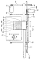
다음으로, 본 발명에 관계되는 화상 형성 장치의 일 예를 도 5 및 6을 참조하여 설명한다. 도 5는 상기 화상 형성 장치의 전체 구성을 설명하는 측면도이고, 도 6은 상기 화상 형성 장치의 주요 부분의 평면도이다.Next, an example of the image forming apparatus according to the present invention will be described with reference to FIGS. 5 and 6. Fig. 5 is a side view illustrating the overall configuration of the image forming apparatus, and Fig. 6 is a plan view of the main part of the image forming apparatus.
상기 화상 형성 장치는, 좌우 측판(미 도시)에 가로놓인 가이드 로드(101) 및 가이드 레일(102)이 주 스캐닝 방향으로 슬라이드 가능하게 캐리지(103)를 지지하고 있어, 상기 캐리지(103)를 주 스캐닝 모터(104)로 구동 풀리(106A) 및 종동 풀리(106B)에 감긴 타이밍 벨트(105)를 거쳐 도 6의 화살표 방향(주 스캐닝 방향)으로 이동시켜 스캐닝한다.In the image forming apparatus, the
예를 들어, 도 7에 도시된 바와 같이 기록 헤드(107)는 주 스캐닝 방향을 따라 상기 캐리지(103) 내에 배치되어 잉크방울을 하향으로 토출하는데, 상기 기록 헤드(107)는 블랙(K), 시안(C), 마젠타(M), 옐로(Y), 엷은 시안(LC), 엷은 마젠타(LM) 및 엷은 옐로(LY)의 각 색의 기록 액체의 잉크방울을 노즐(107n)로부터 토출하는 7개의 독립적인 액체 토출 헤드(107k, 107c, 107m, 107y, 107lc, 107lm 및 107ly)로 구성된다.For example, as shown in FIG. 7, the
또한, 여기서는 독립적인 액체 토출 헤드를 사용하고 있지만, 각 색의 기록 액체의 잉크방울을 토출하는 다수의 노즐 열을 갖는 하나 이상의 헤드를 사용하는 것도 가능하다. 또한, 색의 수 및 배열순서는 앞서 설명한 것에 의해 제한되는 것이 아니며, 도 8에 도시된 바와 같이 4색 헤드의 구성도 가능하다. 또한, 하이라이트 부분에서 옐로 도트는 보기 어려운 성질을 가지기 때문에, 엷은 옐로(LY)를 생략할 수도 있다. 나아가, 고화질을 실현하기 위해 엷은 블랙, 시안, 마젠타, 옐로 및 블랙의 각 색의 농도를 3단계 또는 4단계로 나누는 것도 가능하다.In addition, although an independent liquid ejecting head is used here, it is also possible to use one or more heads having a plurality of nozzle rows for ejecting ink droplets of recording liquids of respective colors. In addition, the number and arrangement order of colors are not limited by the above description, and the configuration of the four-color head is possible as shown in FIG. In addition, since the yellow dot has a hardly seen property in the highlight portion, pale yellow LY can be omitted. Furthermore, in order to realize high quality, it is also possible to divide the density of each color of light black, cyan, magenta, yellow and black into three or four levels.
기록 헤드(107)를 구성하는 잉크젯 헤드로서는, 압전 소자를 이용하는 압전형 엑츄에이터, 발열 저항체 등의 전기-열 변환 소자로 액체의 막 비등(film boiling)에 의한 상 변화를 이용하는 서멀(thermal)형 엑츄에이터, 온도 변화에 의한 금속 상 변화를 이용하는 형상 기억 합금형 엑츄에이터, 정전력(electrostatic force)을 이용하는 정전형 엑츄에이터 등이 될 수 있다.As the inkjet head constituting the
상기 캐리지(103)에는 기록 헤드(107)에 각 색의 잉크를 공급하도록, 각 색용 서브 탱크(108)가 탑재되어 있다. 상기 각각의 서브 탱크(108)에는 잉크 공급관(109)을 통해 장치 본체에 탈착 가능하게 장착되는 메인 탱크(잉크 카트리지)로부터 잉크가 공급된다.Each
한편, 급지 카세트(110) 등의 용지 적재부(압력판)(111)에 적재된 용지(112)를 급지하는 급지부는, 용지 적재부(111)로부터 용지(112)를 1장씩 분리 공급하는 반월 롤러(급지 롤러)(113); 및 급지 롤러에 대향하며 마찰계수가 큰 재질로 이루어진 분리 패드(114)로 구성된다. 상기 분리 패드(114)는 급지 롤러(113)에 대해 바이어스(biased)되어 있다.On the other hand, the paper feeder for feeding the
상기 급지부로부터 급지되는 용지(112)를 기록 헤드(107)의 하측으로 이송하는 이송부는, 용지(112)를 정전 흡착하여 이송하는 이송 벨트(121); 급지부로부터 가이드(115)를 통해 보내지는 용지(112)를 이송 벨트(121)와의 사이에 끼워 이송하기 위한 카운터 롤러(122); 상향으로 보내지는 용지(112)를 대략 90°방향 전환시키고 이송 벨트(121)를 따라가게 하는 이송 가이드(123); 및 고정 부재(124)로 이 송 벨트(121) 측에 바이어스되는 선단 가압 롤러(125)를 포함한다. 또한, 이송 벨트(121)의 표면을 대전하는 대전 수단으로서 대전 롤러(126)가 구성된다.The conveying unit which conveys the
여기에서, 이송 벨트(121)는 무단 벨트이고, 이송 롤러(127)와 텐션 롤러(128)에 감겨 있어, 부 스캐닝 모터(131)로부터 타이밍 벨트(132) 및 타이밍 롤러(133)를 통해 이송 롤러(127)가 회전되는 것으로, 도 6의 벨트의 이송 방향(부 스캐닝 방향)으로 연속적으로 이동하도록 구성된다. 또한, 이송 벨트(121)의 뒷면 측에는 기록 헤드(107)에 의한 화상 형성 영역에 대응하는 가이드 부재(129)가 배치되어 있다.Here, the conveying
이송 벨트(121)의 표면층과 접촉하는 대전 롤러(126)는 이송 벨트(121)의 접선 운동에 의해 구동되어 회전하도록 배치되고, 2.5 N의 압착력이 축의 양단에 가해진다. The charging
또한, 기록 헤드(107)에 기록되는 용지(112)를 배지하는 배지부는, 이송 벨트(121)로부터 용지(112)를 분리하는 분리 클로(claw)(151); 하부 배지 롤러(152); 상부 배지 롤러(153); 및 배지되는 용지(112)를 적재하는 배지 트레이(154)를 포함한다.In addition, the discharge unit for discharging the
또한, 뒤쪽에는 양면 급지 유닛(155)이 탈착 가능하게 장착되어 있다. 상기 양면 급지 유닛(155)은 이송 벨트(121)의 역방향 회전으로 되돌아오는 용지(112)를 집어넣어 반전시키고 다시 카운터 롤러(122)와 이송 벨트(121) 사이에 급지한다.In addition, the double-sided
상기와 같은 구성의 화상 형성 장치에서, 급지부로부터 용지(112)가 1장씩 분리 급지되고, 상향으로 급지되는 용지(112)는 가이드(115)로 안내되며, 이송 벨 트(121)와 카운터 롤러(122) 사이에 끼워져 이송된다. 또한, 용지(112)의 선단은 이송 가이드(123)로 안내되고, 선단 가압 롤러(125)에 의해 눌려져 대략 90°로 이송 방향이 전환된다.In the image forming apparatus having the above-described configuration, the
이때, 제어 회로(미 도시)에 의해 AC 바이어스 공급부로부터 대전 롤러(126)에 교류 전압이 인가되는데, 이송 벨트(121)는 교대 대전 전압 패턴, 즉 이송 벨트(121)가 이동하는 방향인 부 스캐닝 방향으로 플러스 전압과 마이너스 전압이 소정의 폭에 교대로 인가되는 패턴으로 대전된다. 이와 같이 대전된 이송 벨트(121)에 용지(112)가 공급되면, 용지(112)는 이송 벨트(121)에 정전 흡착되어 이송 벨트(121)의 이동에 따라 부 스캐닝 방향으로 이송된다.At this time, an alternating voltage is applied from the AC bias supply to the charging
그 다음, 캐리지(103)를 앞뒤로 이동시키면서, 화상 처리 장치(2)로부터의 화상 데이터에 따라 기록 헤드(107)를 구동함으로써, 정지하고 있는 용지(112)에 잉크방울을 토출하여 1행분을 기록하고, 소정의 양만큼 용지(112)를 이송한 후 다음 행의 기록을 행한다. 기록 종료 신호 또는 용지(112)의 후단이 기록 영역에 도달했음을 알리는 신호에 의해 기록 동작은 종료되고, 용지(112)는 배지 트레이(154)에 배지된다.Then, by moving the
또한, 양면 인쇄의 경우에는 앞면(처음 인쇄되는 면)의 기록이 종료되면, 이송 벨트(121)를 역회전시킴으로써 기록이 끝난 용지(112)를 양면 급지 유닛(155) 내에 보내고, 용지(112)를 반전시키고(뒷면이 인쇄면이 되는 상태로 하고), 다시 카운터 롤러(122)와 이송 벨트(121) 사이에 급지하고, 타이밍 제어를 행하고, 전술한 바와 같이 용지(112)를 이송 벨트(121) 상에 이송하여 뒷면에 기록을 행한 후, 배지 트레이(154)에 배지한다.In the case of double-sided printing, when the recording of the front side (the first surface to be printed) is finished, the
다음으로, 상기 화상 형성 장치의 제어부의 개요에 대해 도 9를 참조하여 설명한다. 도 9는 상기 제어부의 개요를 나타내는 블럭 설명도이다.Next, the outline | summary of the control part of the said image forming apparatus is demonstrated with reference to FIG. 9 is a block explanatory diagram showing an outline of the controller.
상기 제어부(200)는, 본 장치 전체를 제어하는 중앙 처리 유닛(CPU)(201); 상기 CPU에 의해 실행되는 프로그램 및 다른 고정 데이터를 저장하는 롬(ROM)(202); 화상 데이터를 일시적으로 저장하는 램(RAM)(203); 본 장치의 전원이 꺼졌을 때 데이터를 유지하는 재기록 가능한 비휘발성 메모리(rewritable non-volatile memory)(204); 및 화상 데이터에 대한 각종 신호 처리와 재배열을 포함하는 화상 처리와 본 장치 전체를 제어하기 위한 입출력 신호 처리를 수행하는 ASIC(application specification integrated circuit)(205)를 포함한다.The
또한, 상기 제어부(200)는, 퍼스널 컴퓨터 등의 데이터 처리 장치인 호스트(host) 측과 데이터 및 신호를 교환하는 인터페이스(I/F)(206); 기록 헤드(107)를 구동하기 위한 구동 파형을 생성하는 구동 파형 생성부(107); 기록 헤드(107)의 구동을 제어하는 헤드 드라이버(208); 주 스캐닝 모터(104)를 구동하는 주 스캐닝 모터용 드라이버(211); 부 스캐닝 모터(131)를 구동하는 부 스캐닝 모터용 드라이버(213); 대전 롤러(126)에 대해 AC 바이어스 전압을 인가하는 AC 바이어스 공급부(214); 및 각종 센서들(미 도시)로부터의 검지 신호를 입력하는 인터페이스(I/O)(216)를 포함한다.The
또한, 상기 제어부(200)에는 본 장치에 필요한 정보를 입력하고 표시하는 조 작 패널(217)이 연결되어 있다.In addition, the
이때, 상기 제어부(200)는 퍼스널 컴퓨터 등의 화상 처리 장치(2) 등의 호스트 측으로부터의 화상 데이터를 포함하는 인쇄 데이터를 케이블이나 네트(net)를 통해 상기 I/F(206)로 수신한다.At this time, the
상기 CPU(201)는 상기 I/F(206)에 포함되는 수신 버퍼 내에 저장된 인쇄 데이터를 판독 분석하고, ASIC(205)로 상기 데이터를 재배열 처리한 후, 상기 헤드 드라이버(208)에 상기 화상 데이터를 전송한다.The
상기 구동 파형 생성부(207)는 구동 신호의 패턴 데이터를 D/A 변환하는 D/A 변환기 등으로 구성되며, 하나 이상의 구동 신호로 이루어지는 구동 파형을 헤드 드라이버(208)에 출력한다. 상기 헤드 드라이버(208)는 시리얼(serial)로 입력되는 기록 헤드(107)의 1행분에 상당하는 화상 데이터(도트 패턴 데이터)에 근거하여 구동 파형 생성부(207)로부터 부여받은 구동 파형을 구성하는 구동 신호를 기록 헤드(107)의 액츄에이터에 선택적으로 인가하여 헤드를 구동한다.The
도 3이 나타내듯이, 상기 화상 형성 장치(3)에서 출력되는 도트는 전술한 바와 같이 제어된다. "0"은 도트가 찍히지 않음(도트 오프)을, "2"는 통상 잉크를, "1"은 통상 잉크를 희석한 낮은 농도의 엷은 잉크를 나타낸다.As shown in Fig. 3, the dots output from the
또한, 전술한 구동 파형으로서, 예를 들어 1 구동 주기 내에서 다른 크기의 잉크방울을 토출할 수 있는 다수의 구동 파형을 구동 파형 생성부(207)로부터 생성/출력하여, 기록 헤드(107)에 다수의 구동 파형을 선택적으로 부여함으로써, 대, 중, 소 및 널(null)의 4개의 다른 레벨의 도트를 출력하기 위한 도트 지름 변조방 식을 채용하는 것이 가능해진다.Further, as the above-described drive waveforms, for example, a plurality of drive waveforms capable of ejecting ink droplets of different sizes within one drive period are generated / outputted from the drive
또한, 상기 실시예에서는 화상 처리 장치(2)로부터 출력되는 화상을 형성하는 화상 형성 장치로서 잉크젯 기록방식의 화상 형성 장치에 대해 설명하였지만, 예를 들어 전자사진 방식의 화상 형성 장치, 열전사 방식의 화상 형성 장치에도 마찬가지로 적용할 수 있다. 전자사진 방식의 화상 형성 장치에서는 하나의 도트가 형성하는 노광량을 제어하도록 노광 기록에 있어 펄스 폭을 분할함으로써 멀티 레벨의 톤을 표현하거나, 노광으로 사용되는 레이저광의 강도를 조절함으로써 멀티 레벨의 톤을 표현할 수 있다.In the above embodiment, an image forming apparatus of an inkjet recording method has been described as an image forming apparatus for forming an image output from the
또한, 상기 실시예에서는 화상 처리 장치가 본 발명과 관계되는 화상 처리부를 포함하는 구성으로 설명하였지만, 화상 입력 장치 또는 화상 형성 장치에 화상 처리부를 포함하여 구성하는 것도 가능하다. 또한, 본 발명은 복수의 기기들(예를 들어, 호스트 컴퓨터, 인터페이스 기기, 리더(reader), 프린터 등)로 구성된 시스템은 물론, 하나의 기기로 구성되는 장치(예를 들어, 복사기, 팩시밀리 장치 등)에 적용될 수 있다.In addition, in the above embodiment, the image processing apparatus has been described with the configuration including the image processing unit according to the present invention, but it is also possible to include the image processing unit in the image input device or the image forming apparatus. In addition, the present invention is a system consisting of a plurality of devices (for example, a host computer, an interface device, a reader, a printer, etc.), as well as a device (for example, a copier, a facsimile device) Etc.).
또한, 상기 실시예에서 설명한 본 발명에 관계되는 화상 처리부의 작동을 컴퓨터가 실행하도록 하는 소프트웨어 프로그램을 구성할 수도 있다. 이러한 경우, 본 발명에 관계되는 프로그램은 해당 픽셀의 멀티 레벨 화상 데이터에 주변의 이미 양자화가 끝난 픽셀로부터 확산되는 에러를 더한 보정 데이터를 출력하는 단계의 코드(code); 해당 픽셀의 멀티 레벨 화상 데이터에 근거하여 양자화 역치를 설정하는 단계의 코드; 상기 보정 데이터와 양자화 역치를 비교하여 N 레벨 화상 데이터 를 출력하는 단계의 코드; 및 N 레벨 화상 데이터를 생성할 때 발생하는 에러를 산출하는 단계의 코드를 포함한다. 상기 프로그램에서는, 양자화 값을 0, 1, 2, ..., N-1 이라 하고, 양자화 값의 톤을 V0, V1, V2, ..., VN-1 이라 할 때, 적어도 하나의 입력값의 구간 Va ~ Va +1 (0 ≤ a < N-1) 에서 적어도 하나의 역치 Tha + 1는, 입력 톤 값이 υ인 경우, 전술한 [수식 1]에 근거하여 설정된다.Further, a software program may be configured in which a computer executes an operation of the image processing unit according to the present invention described in the above embodiments. In such a case, the program according to the present invention includes code for outputting correction data obtained by adding multi-level image data of a corresponding pixel to an error spreading from neighboring already quantized pixels; Code for setting a quantization threshold based on the multi-level image data of the pixel; Code for outputting N level image data by comparing the correction data with a quantization threshold; And a code of calculating an error occurring when generating the N level image data. In the above program, when the quantization value is 0, 1, 2, ..., N-1, and the tone of the quantization value is V0, V1, V2, ..., VN-1, at least one input value. In the intervals V a to V a +1 (0 ≦ a <N−1), at least one threshold Th a + 1 is set based on
또한, 상기 프로그램은 프로그램 코드를 기록한 기억 매체를 시스템 또는 장치에 공급하고, 그 시스템 또는 장치의 컴퓨터(CPU 또는 MPU)가 기억 매체에 저장된 프로그램 코드를 판독하고 실행하는 것에 의해서도 구현될 수 있다. 이러한 경우, 기억 매체로부터 판독되는 프로그램 코드 자체가 전술한 실시예의 기능을 실현하는 것이 된다.The program can also be implemented by supplying a storage medium on which program code is recorded to a system or apparatus, and by the computer (CPU or MPU) of the system or apparatus reading and executing the program code stored in the storage medium. In such a case, the program code itself read out from the storage medium realizes the functions of the above-described embodiments.
프로그램 코드를 공급하기 위한 기억 매체로는, 예를 들어 플렉시블 디스크(flexible disk), 하드 디스크, 광 디스크, 광자기 디스크, 자기 테이프, 비휘발성 메모리 카드, ROM, USB 메모리 등이 사용될 수 있다.As a storage medium for supplying program codes, for example, a flexible disk, a hard disk, an optical disk, a magneto-optical disk, a magnetic tape, a nonvolatile memory card, a ROM, a USB memory, or the like can be used.
또한, 컴퓨터가 판독하는 프로그램 코드를 실행함으로써 전술한 실시예의 기능을 실현할 뿐만 아니라, 상기 프로그램 코드의 지시에 근거하여 컴퓨터의 OS(운영 시스템)가 실제 처리의 일부 또는 전체를 행함으로써 전술한 실시예의 기능을 실현하는 경우도 포함된다.In addition, by executing the program code read out by the computer, not only the functions of the above-described embodiments are realized, but also the OS (operating system) of the computer performs part or all of the actual processing based on the instruction of the program code, thereby This includes the case where the function is realized.
또한, 기억 매체로부터 판독되는 프로그램 코드가 컴퓨터에 삽입되는 기능 확장 보드나 컴퓨터에 접속되는 기능 확장 유닛에 구비된 메모리에 기록된 후, 상 기 프로그램 코드의 지시에 근거하여 상기 기능 확장 보드나 기능 확장 유닛에 구비된 CPU 등이 실제 처리의 일부 또는 전체를 행함으로써 전술한 실시예의 기능을 실현하는 경우도 포함된다.Further, after the program code read from the storage medium is recorded in the memory provided in the function expansion board inserted into the computer or the function expansion unit connected to the computer, the function expansion board or the function expansion is based on the instruction of the program code. Also included is a case where the CPU or the like provided in the unit implements part or all of the actual processing to realize the functions of the above-described embodiments.
본 발명의 화상 처리 장치, 화상 형성 장치 및 프로그램은 에러 확산 처리 유닛이 인접하는 경계에서 발생하는 줄무늬 형태의 의사 윤곽을 방지함으로써 처리 화상의 품질 저하를 억제하고, 처리 단위를 다수의 작은 영역으로 분할할 수 있게 함으로써 메모리 사용량의 감소를 도모한다.The image processing apparatus, the image forming apparatus, and the program of the present invention suppress the deterioration of the quality of the processed image by preventing the pseudo-diffusion in the form of stripes occurring at the borders adjacent to the error diffusion processing unit, and divide the processing unit into a plurality of small areas By doing so, the memory usage can be reduced.
Claims (20)
Priority Applications (1)
| Application Number | Priority Date | Filing Date | Title |
|---|---|---|---|
| KR1020067013156A KR100822466B1 (en) | 2004-10-29 | 2005-10-27 | An image processing apparatus, an image forming apparatus, and a recording medium recording a program |
Applications Claiming Priority (2)
| Application Number | Priority Date | Filing Date | Title |
|---|---|---|---|
| JPJP-P-2004-00314941 | 2004-10-29 | ||
| KR1020067013156A KR100822466B1 (en) | 2004-10-29 | 2005-10-27 | An image processing apparatus, an image forming apparatus, and a recording medium recording a program |
Publications (2)
| Publication Number | Publication Date |
|---|---|
| KR20070017306A KR20070017306A (en) | 2007-02-09 |
| KR100822466B1 true KR100822466B1 (en) | 2008-04-16 |
Family
ID=41345486
Family Applications (1)
| Application Number | Title | Priority Date | Filing Date |
|---|---|---|---|
| KR1020067013156A Expired - Fee Related KR100822466B1 (en) | 2004-10-29 | 2005-10-27 | An image processing apparatus, an image forming apparatus, and a recording medium recording a program |
Country Status (1)
| Country | Link |
|---|---|
| KR (1) | KR100822466B1 (en) |
Citations (6)
| Publication number | Priority date | Publication date | Assignee | Title |
|---|---|---|---|---|
| JPH07111591A (en) * | 1993-06-24 | 1995-04-25 | Seiko Epson Corp | Image processing device |
| KR970057708A (en) * | 1995-12-20 | 1997-07-31 | 김광호 | N x n Window Processing Method and System in Image Processing System |
| KR19980069987A (en) * | 1997-01-08 | 1998-10-26 | 포맨 제프리 엘 | Invisible image watermark for image verification |
| KR19990072863A (en) * | 1998-02-24 | 1999-09-27 | 이데이 노부유끼 | Image processing method and apparatus |
| JP2003219161A (en) * | 2002-01-24 | 2003-07-31 | Ricoh Co Ltd | Image forming apparatus, image forming method, program, and recording medium |
| JP2004112089A (en) * | 2002-09-13 | 2004-04-08 | Ricoh Co Ltd | Image processing device, image recording device, and program |
-
2005
- 2005-10-27 KR KR1020067013156A patent/KR100822466B1/en not_active Expired - Fee Related
Patent Citations (6)
| Publication number | Priority date | Publication date | Assignee | Title |
|---|---|---|---|---|
| JPH07111591A (en) * | 1993-06-24 | 1995-04-25 | Seiko Epson Corp | Image processing device |
| KR970057708A (en) * | 1995-12-20 | 1997-07-31 | 김광호 | N x n Window Processing Method and System in Image Processing System |
| KR19980069987A (en) * | 1997-01-08 | 1998-10-26 | 포맨 제프리 엘 | Invisible image watermark for image verification |
| KR19990072863A (en) * | 1998-02-24 | 1999-09-27 | 이데이 노부유끼 | Image processing method and apparatus |
| JP2003219161A (en) * | 2002-01-24 | 2003-07-31 | Ricoh Co Ltd | Image forming apparatus, image forming method, program, and recording medium |
| JP2004112089A (en) * | 2002-09-13 | 2004-04-08 | Ricoh Co Ltd | Image processing device, image recording device, and program |
Also Published As
| Publication number | Publication date |
|---|---|
| KR20070017306A (en) | 2007-02-09 |
Similar Documents
| Publication | Publication Date | Title |
|---|---|---|
| US8626623B2 (en) | Image processing apparatus, image processing method, and recording medium | |
| EP1986855B1 (en) | Image processing method, recorded matter, program, image processing apparatus, image forming apparatus, image forming system and ink | |
| CN100527779C (en) | An image-processing apparatus, an image- forming apparatus, and a program | |
| JP4825180B2 (en) | Image processing method, image processing apparatus, image forming apparatus, image forming system, program, and storage medium | |
| JP5369851B2 (en) | Image processing apparatus, image processing method, computer-executable program, and computer-readable recording medium | |
| EP2062428B1 (en) | Image processing apparatus, program, image forming apparatus, image forming method, and dither matrix | |
| US8388092B2 (en) | Image forming apparatus and image forming method | |
| JP2004284279A (en) | Image processing device/method and image processing program | |
| JP2006173929A (en) | Image processing method, program, image processing apparatus, and image forming apparatus | |
| US8976416B2 (en) | Image processing apparatus and method thereof | |
| CN102160367B (en) | Image processing apparatus, image processing method | |
| JP5262485B2 (en) | Image processing apparatus, image processing method, program, recording medium, printing system, and image forming apparatus | |
| JP2012126040A (en) | Image forming apparatus | |
| KR100822466B1 (en) | An image processing apparatus, an image forming apparatus, and a recording medium recording a program | |
| JP4257087B2 (en) | Image processing apparatus, image recording apparatus, and program | |
| JP5332966B2 (en) | Image processing method, image processing apparatus, program, recording medium, and image forming apparatus | |
| JP2004168000A (en) | Inkjet recording device |
Legal Events
| Date | Code | Title | Description |
|---|---|---|---|
| A201 | Request for examination | ||
| PA0105 | International application |
St.27 status event code: A-0-1-A10-A15-nap-PA0105 |
|
| PA0201 | Request for examination |
St.27 status event code: A-1-2-D10-D11-exm-PA0201 |
|
| PG1501 | Laying open of application |
St.27 status event code: A-1-1-Q10-Q12-nap-PG1501 |
|
| E902 | Notification of reason for refusal | ||
| PE0902 | Notice of grounds for rejection |
St.27 status event code: A-1-2-D10-D21-exm-PE0902 |
|
| P11-X000 | Amendment of application requested |
St.27 status event code: A-2-2-P10-P11-nap-X000 |
|
| P13-X000 | Application amended |
St.27 status event code: A-2-2-P10-P13-nap-X000 |
|
| E701 | Decision to grant or registration of patent right | ||
| PE0701 | Decision of registration |
St.27 status event code: A-1-2-D10-D22-exm-PE0701 |
|
| GRNT | Written decision to grant | ||
| PR0701 | Registration of establishment |
St.27 status event code: A-2-4-F10-F11-exm-PR0701 |
|
| PR1002 | Payment of registration fee |
St.27 status event code: A-2-2-U10-U12-oth-PR1002 Fee payment year number: 1 |
|
| PG1601 | Publication of registration |
St.27 status event code: A-4-4-Q10-Q13-nap-PG1601 |
|
| PR1001 | Payment of annual fee |
St.27 status event code: A-4-4-U10-U11-oth-PR1001 Fee payment year number: 4 |
|
| FPAY | Annual fee payment |
Payment date: 20120402 Year of fee payment: 5 |
|
| PR1001 | Payment of annual fee |
St.27 status event code: A-4-4-U10-U11-oth-PR1001 Fee payment year number: 5 |
|
| FPAY | Annual fee payment |
Payment date: 20130328 Year of fee payment: 6 |
|
| PR1001 | Payment of annual fee |
St.27 status event code: A-4-4-U10-U11-oth-PR1001 Fee payment year number: 6 |
|
| PR1001 | Payment of annual fee |
St.27 status event code: A-4-4-U10-U11-oth-PR1001 Fee payment year number: 7 |
|
| LAPS | Lapse due to unpaid annual fee | ||
| PC1903 | Unpaid annual fee |
St.27 status event code: A-4-4-U10-U13-oth-PC1903 Not in force date: 20150409 Payment event data comment text: Termination Category : DEFAULT_OF_REGISTRATION_FEE |
|
| PC1903 | Unpaid annual fee |
St.27 status event code: N-4-6-H10-H13-oth-PC1903 Ip right cessation event data comment text: Termination Category : DEFAULT_OF_REGISTRATION_FEE Not in force date: 20150409 |
|
| P22-X000 | Classification modified |
St.27 status event code: A-4-4-P10-P22-nap-X000 |
|
| R18-X000 | Changes to party contact information recorded |
St.27 status event code: A-5-5-R10-R18-oth-X000 |