KR100761849B1 - Semiconductor memory device can reduce production costs - Google Patents
Semiconductor memory device can reduce production costs Download PDFInfo
- Publication number
- KR100761849B1 KR100761849B1 KR1020060058877A KR20060058877A KR100761849B1 KR 100761849 B1 KR100761849 B1 KR 100761849B1 KR 1020060058877 A KR1020060058877 A KR 1020060058877A KR 20060058877 A KR20060058877 A KR 20060058877A KR 100761849 B1 KR100761849 B1 KR 100761849B1
- Authority
- KR
- South Korea
- Prior art keywords
- memory
- address
- memory area
- cell array
- area
- Prior art date
- Legal status (The legal status is an assumption and is not a legal conclusion. Google has not performed a legal analysis and makes no representation as to the accuracy of the status listed.)
- Expired - Fee Related
Links
Images

Classifications
-
- G—PHYSICS
- G11—INFORMATION STORAGE
- G11C—STATIC STORES
- G11C29/00—Checking stores for correct operation ; Subsequent repair; Testing stores during standby or offline operation
- G11C29/70—Masking faults in memories by using spares or by reconfiguring
- G11C29/78—Masking faults in memories by using spares or by reconfiguring using programmable devices
- G11C29/80—Masking faults in memories by using spares or by reconfiguring using programmable devices with improved layout
- G11C29/808—Masking faults in memories by using spares or by reconfiguring using programmable devices with improved layout using a flexible replacement scheme
-
- G—PHYSICS
- G11—INFORMATION STORAGE
- G11C—STATIC STORES
- G11C29/00—Checking stores for correct operation ; Subsequent repair; Testing stores during standby or offline operation
- G11C29/04—Detection or location of defective memory elements, e.g. cell constructio details, timing of test signals
- G11C29/08—Functional testing, e.g. testing during refresh, power-on self testing [POST] or distributed testing
- G11C29/12—Built-in arrangements for testing, e.g. built-in self testing [BIST] or interconnection details
- G11C29/18—Address generation devices; Devices for accessing memories, e.g. details of addressing circuits
- G11C29/24—Accessing extra cells, e.g. dummy cells or redundant cells
Landscapes
- For Increasing The Reliability Of Semiconductor Memories (AREA)
Abstract
생산비용을 줄일 수 있는 반도체 메모리 장치가 개시된다. 본 발명의 실시예에 따른 반도체 메모리 장치는 복수의 메모리 영역들을 구비하며, 복수의 메모리 영역들 각각은 노말 셀 어레이 및 상기 노말 셀 어레이 중 결합이 있는 셀들을 구제하기 위한 리던던시 셀 어레이를 구비한다. 상기 복수의 메모리 영역들 중 제 1 메모리 영역의 리던던시 셀 어레이의 크기는 나머지 메모리 영역들의 리던던시 셀 어레이의 크기보다 크다. 본 발명의 실시예에 따른 반도체 메모리 장치는 메모리 어레이에 결함 셀이 존재하는 경우에도 사용할 수 있으므로, 반도체 메모리 장치의 생산에 있어서 생산 수율을 높일 수 있으며, 제조 비용를 절감할 수 있는 장점이 있다. Disclosed are a semiconductor memory device capable of reducing production costs. A semiconductor memory device according to an embodiment of the present invention includes a plurality of memory regions, each of the plurality of memory regions including a normal cell array and a redundancy cell array for saving cells having a combination of the normal cell arrays. The size of the redundancy cell array of the first memory area among the plurality of memory areas is larger than the size of the redundancy cell array of the remaining memory areas. Since the semiconductor memory device according to the embodiment of the present invention can be used even when a defective cell exists in the memory array, the production yield can be increased and the manufacturing cost can be reduced in the production of the semiconductor memory device.
Description
본 발명의 상세한 설명에서 인용되는 도면을 보다 충분히 이해하기 위하여 각 도면의 간단한 설명이 제공된다. BRIEF DESCRIPTION OF THE DRAWINGS In order to better understand the drawings cited in the detailed description of the invention, a brief description of each drawing is provided.
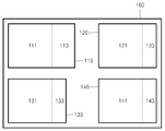
도 1은 본 발명의 실시예에 따른 반도체 메모리 장치의 블록도이다. 1 is a block diagram of a semiconductor memory device according to an embodiment of the present invention.
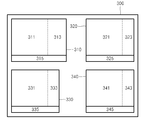
도 2는 본 발명의 다른 실시예에 따른 반도체 메모리 장치의 블록도이다. 2 is a block diagram of a semiconductor memory device according to another embodiment of the present invention.
도 3은 본 발명의 또 다른 실시예에 따른 반도체 메모리 장치의 블록도이다. 3 is a block diagram of a semiconductor memory device according to still another embodiment of the present invention.
본 발명은 반도체 메모리 장치에 관한 것으로, 특히 메모리 어레이에 결함 셀이 존재하는 경우에도 사용할 수 있는 반도체 메모리 장치에 관한 것이다. BACKGROUND OF THE INVENTION 1. Field of the Invention The present invention relates to semiconductor memory devices, and more particularly, to semiconductor memory devices that can be used even when defective cells exist in a memory array.
반도체 메모리 장치의 집적도가 증가함에 따라 반도체 메모리 장치의 가격 또한 비싸지게 된다. 따라서 반도체 생산 회사들에게 있어서 반도체 메모리 장치의 가격을 낮추는 것은 중요한 문제가 된다. As the degree of integration of semiconductor memory devices increases, the price of semiconductor memory devices also becomes expensive. Therefore, lowering the price of semiconductor memory devices is an important issue for semiconductor production companies.
일반적으로 반도체 메모리 장치의 가격을 낮추는 방법으로는 반도체 메모리 장치의 메모리 셀 어레이를 구성하는 셀 크기를 작게 하여 반도체 메모리 장치의 칩 크기를 감소시키거나 또는 생산수율(yield, 또는 수율)을 향상시켜 제조 가격을 감소시키는 방법 등이 있다. In general, a method of lowering the price of a semiconductor memory device may be manufactured by reducing the size of a cell constituting the memory cell array of the semiconductor memory device to reduce the chip size of the semiconductor memory device or to improve the yield or yield. There are ways to reduce the price.
셀 크기를 작게 하여 반도체 메모리 장치의 칩 크기를 작게하는 방법은 제조 장비의 투자가 수반되어야 하는 단점이 있다. 따라서 수율을 향상시켜 제조 가격을 감소시키는 방법이 필요하다. The method of reducing the chip size of the semiconductor memory device by reducing the cell size has a disadvantage that an investment in manufacturing equipment must be accompanied. Therefore, there is a need for a method of improving the yield to reduce the manufacturing cost.
그러나 반도체 메모리 장치의 수율을 향상시키는 데 있어서 가장 큰 문제점들 중에 하나는 수 비트 정도의 비트 에러가 발생하는 경우에도 반도체 장치를 사용하지 못하는 것이다. 따라서 수 비트 정도의 비트 에러가 발생하는 경우에도 반도체 메모리 장치를 사용할 수 있도록 할 필요가 있다. However, one of the biggest problems in improving the yield of the semiconductor memory device is that the semiconductor device cannot be used even when a bit error of several bits occurs. Therefore, it is necessary to enable the semiconductor memory device to be used even when a bit error of about several bits occurs.
본 발명이 이루고자하는 기술적 과제는 메모리 어레이에 결함 셀이 존재하는 경우에도 사용할 수 있는 반도체 메모리 장치를 제공하는데 있다. An object of the present invention is to provide a semiconductor memory device that can be used even when a defective cell exists in the memory array.
상기 기술적 과제를 달성하기 위한 본 발명의 실시예에 따른 반도체 메모리 장치는 복수의 메모리 영역들을 구비하며, 복수의 메모리 영역들 각각은 노말 셀 어레이 및 상기 노말 셀 어레이 중 결합이 있는 셀들을 구제하기 위한 리던던시 셀 어레이를 구비한다. 상기 복수의 메모리 영역들 중 제 1 메모리 영역의 리던던시 셀 어레이의 크기는 나머지 메모리 영역들의 리던던시 셀 어레이의 크기보다 크다. A semiconductor memory device according to an embodiment of the present invention for achieving the above technical problem is provided with a plurality of memory regions, each of the plurality of memory regions for the relief of cells having a combination of the normal cell array and the normal cell array A redundancy cell array is provided. The size of the redundancy cell array of the first memory area among the plurality of memory areas is larger than the size of the redundancy cell array of the remaining memory areas.
상기 제 1 메모리 영역은 시스템 소프트웨어의 동작을 위한 시스템 메모리 영역이다. The first memory area is a system memory area for operation of system software.
상기 나머지 메모리 영역들은 정보 데이터의 동작을 위한 데이터 메모리 영역이다. The remaining memory areas are data memory areas for operation of information data.
상기 제 1 메모리 영역의 리던던시 셀 어레이는 비트 단위의 결합까지 구제한다. The redundancy cell array of the first memory area may be repaired up to a bitwise combination.
상기 나머지 메모리 영역들의 리던던시 셀 어레이는 로우단위/컬럼단위의 결함을 구제한다. The redundancy cell array of the remaining memory areas repairs defects on a row / column basis.
상기 기술적 과제를 달성하기 위한 본 발명의 다른 실시예에 따른 반도체 메모리 장치는 복수의 메모리 영역들을 구비하며, 상기 복수의 메모리 영역들 각각은, 노말 셀 어레이, 상기 노말 셀 어레이 중 결합이 있는 셀들을 구제하기 위한 리던던시 셀 어레이, 및 어드레스 지시부를 구비한다. 어드레스 지시부는 상기 메모리 영역의 어드레스 나타낸다. According to another aspect of the present invention, a semiconductor memory device includes a plurality of memory regions, and each of the plurality of memory regions may include a cell having a combination of a normal cell array and a normal cell array. A redundancy cell array for addressing, and an address indicating section. The address indicating section shows an address of the memory area.
상기 복수의 메모리 영역들 중 제 1 메모리 영역에 결함이 있고 나머지 메모리 영역들 중에서 결함이 없는 메모리 영역이 존재하는 경우, 상기 제 1 메모리 영역의 어드레스와 상기 결함이 없는 메모리 영역의 어드레스가 서로 치환된다. When a defect exists in a first memory area among the plurality of memory areas and a defect free memory area exists among the remaining memory areas, an address of the first memory area and an address of the defect free memory area are replaced with each other. .
상기 결함이 없는 메모리 영역의 어드레스 지시부는 상기 제 1 메모리 영역의 어드레스를 나타내도록 설정되고, 상기 제 1 메모리 영역의 어드레스 지시부는 상기 결함이 없는 메모리 영역의 어드레스를 나타내도록 함으로써 어드레스가 서로 치환된다. The address indicating section of the defect free memory area is set to indicate the address of the first memory area, and the address indicating section of the first memory area indicates the address of the defect free memory area so that addresses are replaced with each other.
상기 반도체 메모리 장치는 상기 제 1 영역의 어드레스와 상기 결함이 없는 메모리 영역의 어드레스가 서로 치환되도록, 상기 복수의 메모리 영역의 어드레스 지시부를 설정하는 어드레스 치환부를 더 구비할 수 있다. The semiconductor memory device may further include an address replacement unit configured to set an address indicating unit of the plurality of memory regions such that an address of the first region and an address of the defect-free memory region are replaced with each other.
상기 제 1 메모리 영역은 시스템 소프트웨어의 동작을 위한 시스템 메모리 영역인 것을 특징으로 하는 반도체 메모리 장치. And the first memory area is a system memory area for operation of system software.
상기 어드레스 지시부는 전기 퓨즈(e-fuse)일 수도 있다. The address indicator may be an electric fuse.
상기 기술적 과제를 달성하기 위한 본 발명의 또 다른 실시예에 따른 반도체 메모리 장치는 복수의 메모리 영역들을 구비하며, 상기 복수의 메모리 영역들 각각은 노말 셀 어레이, 상기 노말 셀 어레이 중 결합이 있는 셀들을 구제하기 위한 리던던시 셀 어레이, 및 어드레스 지시부를 구비한다. 어드레스 지시부는 메모리 영역의 어드레스를 나타낸다. 상기 복수의 메모리 영역들 중 제 1 메모리 영역의 리던던시 셀 어레이의 크기는 나머지 메모리 영역들의 리던던시 셀 어레이의 크기보다 크다. According to another aspect of the present invention, a semiconductor memory device includes a plurality of memory regions, and each of the plurality of memory regions includes a cell having a combination of a normal cell array and the normal cell array. A redundancy cell array for addressing, and an address indicating section. The address indicating section indicates an address of the memory area. The size of the redundancy cell array of the first memory area among the plurality of memory areas is larger than the size of the redundancy cell array of the remaining memory areas.
상기 제 1 메모리 영역에 결함이 있고 상기 나머지 메모리 영역들 중에서 결함이 없는 메모리 영역이 존재하는 경우, 상기 제 1 메모리 영역의 어드레스와 상기 결함이 없는 메모리 영역의 어드레스가 서로 치환된다. When the first memory area is defective and there is no defective memory area among the remaining memory areas, an address of the first memory area and an address of the non-defective memory area are replaced with each other.
상기 결함이 없는 메모리 영역의 어드레스 지시부는 상기 제 1 메모리 영역의 어드레스를 나타내도록 설정되고, 상기 제 1 메모리 영역의 어드레스 지시부는 상기 결함이 없는 메모리 영역의 어드레스를 나타내도록 함으로써 어드레스가 서로 치환된다. The address indicating section of the defect free memory area is set to indicate the address of the first memory area, and the address indicating section of the first memory area indicates the address of the defect free memory area so that addresses are replaced with each other.
상기 반도체 메모리 장치는 상기 제 1 영역의 어드레스와 상기 결함이 없는 메모리 영역의 어드레스가 서로 치환되도록, 상기 복수의 메모리 영역의 어드레스 지시부를 설정하는 어드레스 치환부를 더 구비할 수 있다. The semiconductor memory device may further include an address replacement unit configured to set an address indicating unit of the plurality of memory regions such that an address of the first region and an address of the defect-free memory region are replaced with each other.
상기 제 1 메모리 영역은 시스템 소프트웨어의 동작을 위한 시스템 메모리 영역이다. The first memory area is a system memory area for operation of system software.
상기 복수의 메모리 영역들은 뱅크들이거나 또는 블록들일 수 있다. The plurality of memory regions may be banks or blocks.
본 발명과 본 발명의 동작상의 이점 및 본 발명의 실시에 의하여 달성되는 목적을 충분히 이해하기 위해서는 본 발명의 바람직한 실시예를 예시하는 첨부 도면 및 도면에 기재된 내용을 참조하여야 한다. DETAILED DESCRIPTION In order to fully understand the present invention, the operational advantages of the present invention, and the objects achieved by the practice of the present invention, reference should be made to the accompanying drawings which illustrate preferred embodiments of the present invention and the contents described in the drawings.
이하, 첨부한 도면을 참조하여 본 발명의 바람직한 실시예를 설명함으로써, 본 발명을 상세히 설명한다. 각 도면에 제시된 동일한 참조부호는 동일한 부재를 나타낸다. Hereinafter, exemplary embodiments of the present invention will be described in detail with reference to the accompanying drawings. Like reference numerals in the drawings denote like elements.
일반적으로 반도체 메모리 장치가 사용되는 시스템에서, 반도체 메모리 장치는 시스템 OS(operation system) 등의 시스템 소프트웨어가 동작하는 시스템 메모리 영역과 비디오 정보, 음성 정보 등의 데이터가 동작하는 데이터 메모리 영역으로 구분되어 사용된다. In general, in a system in which a semiconductor memory device is used, a semiconductor memory device is divided into a system memory area in which system software such as a system operating system (OS) operates and a data memory area in which data such as video information and voice information operate. do.
특히 모바일 메모리(mobile memery) 장치나 그래픽 메모리(graphic memory) 장치에서는 시스템 메모리 영역 보다는 데이터 메모리 영역이 차지하는 비중이 상대적으로 더 크다. In particular, in the mobile memory device or the graphic memory device, the data memory area is relatively larger than the system memory area.
시스템 메모리 영역에 에러가 있는 경우, 그 에러가 몇 비트에 불과하다고 하더라도, 몇 비트에 불과한 에러는 시스템의 동작에 큰 영향을 줄 수 있다. 이에 반해, 데이터 메모리 영역에 에러가 포함되는 경우, 그 에러가 몇 비트에 불과하다 면, 데이터에 의해 표현되는 객체의 질에 저하(예를 들어 그래픽 메모리 영역의 경우에는 화질의 저하)가 있을 뿐이고, 전체 시스템의 동작에는 아무런 문제가 없다. If there is an error in the system memory area, even if the error is only a few bits, an error of only a few bits can greatly affect the operation of the system. On the other hand, when an error is included in the data memory area, if the error is only a few bits, there is only a deterioration in the quality of the object represented by the data (for example, deterioration in image quality in the graphic memory area). There is no problem with the operation of the whole system.
예를 들어, 모바일 메모리 장치에서 처리해야 하는 데이터의 상당 부분은 비휘발성 메모리 장치(예를 들어, Flash 메모리)로부터 획득되는데, 비휘발성 메모리 장치는 일부의 결함 비트들을 허용하므로, 비휘발성 메모리 장치로부터 데이터를 획득하는 반도체 메모리 장치의 모든 셀들이 결함이 없어야 한다는 것은 의미가 없다. For example, much of the data that must be processed in a mobile memory device is obtained from a nonvolatile memory device (e.g., Flash memory), which allows some of the defective bits and thus from the nonvolatile memory device. It is meaningless that all cells of the semiconductor memory device acquiring data should be free of defects.
또한 일반적으로 그래픽 메모리 장치의 경우, 몇 개의 결함 비트들이 포함되어 있는 경우 그래픽 메모리 장치에 저장된 데이터에 의해 표시되는 영상 중 결함 비트들에 대응하는 부분은 사용자가 인식할 수 없다는 것이 널리 알려져 있다. In general, in the case of a graphic memory device, when some defect bits are included, it is widely known that a part corresponding to the defect bits of an image displayed by data stored in the graphic memory device cannot be recognized by the user.
따라서 본 발명에서는 상술한 바와 같은 메모리 장치의 일반적인 특성을 이용하여 결함 셀이 존재하는 반도체 메모리 장치도 사용할 수 있도록 한다. 결함 셀이 존재하는 반도체 메모리 장치를 사용할 수 있도록 하기 위해서는 다음과 같은 조건이 만족되어야 한다. Therefore, in the present invention, the semiconductor memory device in which the defective cell exists can also be used by using the general characteristics of the memory device as described above. In order to be able to use a semiconductor memory device in which a defective cell exists, the following conditions must be satisfied.
1. 반도체 메모리 장치의 시스템 메모리 영역에서는 결함 셀이 전혀 없어야 한다. 1. There should be no defective cells in the system memory area of the semiconductor memory device.
2. 반도체 메모리 장치의 데이터 메모리 영역에서는 몇 개의 결함 셀이 허용될 수 있다. 2. Several defective cells can be allowed in the data memory area of the semiconductor memory device.
상술한 조건이 만족되기 위해서는, 반도체 메모리 장치의 전체 영역 중 미리 정의된 일부 영역은 모든 셀이 결함이 없이 패스되는 패스 셀들로 구성되어야 하 며, 이하에서 설명될 본 발명의 실시예들은 이러한 조건을 만족한다. 이하 도 1 내지 도 3을 참조하여 본 발명의 실시예들에 대해 설명한다. In order for the above condition to be satisfied, some predefined areas of the entire area of the semiconductor memory device must be composed of pass cells through which all cells pass without defects. Satisfies. Hereinafter, embodiments of the present invention will be described with reference to FIGS. 1 to 3.
도 1은 본 발명의 실시예에 따른 반도체 메모리 장치의 블록도이다. 도 1에 도시된 반도체 메모리 장치는 비대칭적인 리던던시 셀 어레이 배치 방법을 이용하여 미리 정의된 특정 메모리 영역(예를 들어 뱅크 또는 블록)에서 결함 셀이 발생할 가능성을 줄이다. 1 is a block diagram of a semiconductor memory device according to an embodiment of the present invention. The semiconductor memory device shown in FIG. 1 uses an asymmetric redundancy cell array arrangement to reduce the likelihood of defective cells occurring in a particular memory region (eg, bank or block) predefined.
즉, 미리 정의된 특정 메모리 영역에는 리던던시 셀 어레이를 더 많이 배치하고, 그 이외의 메모리 영역들에는 로우성/컬럼성 결함 만을 구제할 정도의 리던던시 셀 어레이를 배치함으로써, 특정 메모리 영역은 모든 셀이 패스 셀들로 구성될 수 있도록 하고 나머지 영역에서는 몇 개의 결함 셀 정도는 허용될 수 있도록 한다. That is, by arranging more redundancy cell arrays in a specific predefined memory region and redundancy cell arrays in which only the low / column defects are remedied in other memory regions, a specific memory region is determined by all cells. It can be made up of pass cells and a few defective cells can be tolerated in the remaining areas.
도 1을 참조하면, 반도체 메모리 장치(100)는 복수의 메모리 영역들(110 내지 140)을 구비한다. 복수의 메모리 영역들은 메모리 뱅크일 수도 있고 메모리 블록일 수도 있다. Referring to FIG. 1, the
이하의 설명에서는 시스템 메모리 영역이 전체 반도체 메모리 장치의 1/4로 정의된 경우를 가정하여 설명할 것이나, 본 발명이 속하는 기술분야에서 통상의 지식을 가진 자는 시스템 메모리 영역이 다른 비율로 정의된 경우에 대해서도 본 발명이 적용될 수 있음을 알 것이다. In the following description, a description will be given on the assumption that the system memory area is defined as one-fourth of the entire semiconductor memory device. However, a person having ordinary skill in the art may define the system memory area as another ratio. It will be appreciated that the present invention can also be applied to.
도 1에서 제 1 메모리 영역(110)은 시스템 메모리 영역이고, 나머지 메모리 영역들은 데이터 메모리 영역으로 설정된 것으로 한다. 한편 복수의 메모리 영역들 각각(110 내지 140)은 노말 셀 어레이(111, 121, 131, 141) 및 리던던시 셀 어레이(113, 123, 133, 143)를 구비한다. 리던던시 셀 어레이(113, 123, 133, 143)는 각각 노말 셀 어레이(111, 121, 131, 141)의 결함을 구제하기 위한 것이다. In FIG. 1, the
도 1에 도시된 바와 같이, 제 1 메모리 영역(110)의 리던던시 셀 어레이(113)의 크기는 나머지 메모리 영역들(120, 130, 140)의 리던던시 셀 어레이(123, 133, 143)의 크기보다 크며, 리던던시 셀 어레이(113)의 크기는 리던던시 셀 어레이(123, 133, 143)의 크기의 2배인 것이 바람직하다. As shown in FIG. 1, the size of the
리던던시 셀 어레이(113)의 크기를 크게 함으로써 제 1 메모리 영역에서 발생되는 결함 셀이 구제되는 확률을 높일 수 있으며, 따라서 제 1 메모리 영역(110)에서 모든 셀들이 패스 셀이 될 수 있도록 한다. By increasing the size of the
한편, 제 1 메모리 영역(110)의 모든 셀들이 패스 셀이 될 수 있도록 하기 위해서, 리던던시 셀 어레이(113)는 비트 단위의 결합까지 구제하여야 한다. 반면, 상술한 바와 같이, 리던던시 셀 어레이들(123, 133, 143)은 로우단위/컬럼단위의 결함을 구제하는 것이 바람직하다. Meanwhile, in order to allow all the cells of the
도 2는 본 발명의 다른 실시예에 따른 반도체 메모리 장치의 블록도이다. 도 2의 실시예는 반도체 메모리 장치를 테스트한 후 미리 정의된 특정 메모리 영역에 리던던시 셀 어레이로도 구제할 수 없는 결함이 있는 경우를 가정한다. 2 is a block diagram of a semiconductor memory device according to another embodiment of the present invention. The embodiment of FIG. 2 assumes that after testing a semiconductor memory device, there is a defect that cannot be repaired even by a redundancy cell array in a predetermined memory area.
만약 특정 메모리 영역 이외의 나머지 메모리 영역 중 결함 셀이 발생하지 않은 메모리 영역이 있다면, 특정 메모리 영역과 결함 셀이 발생하지 않은 메모리 영역을 서로 바꾸는 방식을 이용한다. 즉, 특정 메모리 영역을 데이터 메모리 영역 으로 사용하고, 결함 셀이 발생하지 않은 메모리 영역을 시스템 메모리 영역으로 사용함으로써, 결함 셀이 있는 반도체 메모리 장치가 사용될 수 있도록 할 수 있다. If there is a memory area in which the defective cells do not occur among the remaining memory areas other than the specific memory area, a method of swapping the specific memory area and the memory area in which the defective cell does not occur is used. That is, by using a specific memory area as a data memory area and using a memory area where no defective cell has occurred as a system memory area, a semiconductor memory device having defective cells can be used.
도 2를 참조하면, 반도체 메모리 장치(200)는 복수의 메모리 영역들(210 내지 240)을 구비한다. 복수의 메모리 영역들(210, 220, 230, 240) 각각은 노말 셀 어레이(211, 221, 231, 241), 리던던시 셀 어레이(213, 223, 233, 243), 및 어드레스 지시부(215, 225, 235, 245)를 구비한다. 2, the
어드레스 지시부(215, 225, 235, 245)는 각각 복수의 메모리 영역(210 내지 240)의 어드레스 나타낸다. The
도 1의 반도체 메모리 장치와 달리, 리던던시 셀 어레이(213, 223, 233, 243)의 크기는 문제되지 않는다. 즉, 리던던시 셀 어레이(213, 223, 233, 243)의 크기가 서로 같아도 되고, 서로 달라도 된다. Unlike the semiconductor memory device of FIG. 1, the size of the
반도체 메모리 장치(200)에서 중요한 것은 각각의 메모리 영역들이 서로 치환될 수 있다는 점이며, 이러한 치환은 각각의 메모리 영역들에 대해 디폴트로 부여된 어드레스를 치환함으로써 가능하다. What is important in the
이하의 설명에서는 반도체 메모리 장치(200)의 제 1 메모리 영역(210)이 특정 메모리 영역으로 디폴트로 정의되어 있고, 제 1 메모리 영역(210)의 디폴트 어드레스가 00, 메모리 영역(220)의 디폴트 어드레스가 01, 메모리 영역(230)의 디폴트 어드레스가 10, 그리고 메모리 영역(240)의 디폴트 어드레스가 11인 경우를 가정하여 설명한다. 본 발명의 실시예에서 제 1 메모리 영역(210)은 시스템 소프트웨 어의 동작을 위한 시스템 메모리 영역인 것이 바람직하다. In the following description, the
반도체 메모리 장치를 테스트한 결과 특정 메모리 영역으로 정의되어 있는 리던던시 셀 어레이(213)로도 구제할 수 없는 결함이 제 1 메모리 영역에서 발생한 경우, 종래에는 이러한 반도체 메모리 장치를 사용하지 않았다. As a result of testing the semiconductor memory device, when a defect occurs in the first memory area that cannot be repaired by the
그러나 이러한 경우에도, 예를 들어 메모리 영역(240)에서 결함이 발생하지 않았다면(리던던시 셀 어레이에 의해 모든 결함 셀들이 구제되는 경우를 포함), 제 1 메모리 영역(210)과 메모리 영역(240)을 바꿈으로써 반도체 메모리 장치가 사용되도록 할 수 있다. However, even in this case, if the defect does not occur in the memory area 240 (including the case where all defective cells are repaired by the redundancy cell array), the
이 때, 제 1 메모리 영역(210)과 메모리 영역(240)을 바꾼다는 의미는, 외부에서 볼 때 제 1 메모리 영역(210)의 어드레스가 11이고 메모리 영역(240)의 어드레스가 00으로 인식되면 된다. 따라서 제 1 메모리 영역(240)의 어드레스와 메모리 영역(240)의 어드레스를 서로 치환함으로써 메모리 영역이 바뀌도록 할 수 있다. In this case, the meaning of swapping the
메모리 영역들(210 내지 240)의 어드레스를 치환하기 위해서, 본 발명에서는 어드레스 지시부(215, 225, 235, 245)를 이용한다. 상술한 바와 같이 어드레스 지시부(215, 225, 235, 245)는 메모리 영역들(210 내지 240)의 어드레스를 나타낸다. In order to replace the addresses of the
디폴트 상태에서 어드레스 지시부(215)는 00의 어드레스를 나타내고, 어드레스 지시부(225)는 01의 어드레스를 나타내고, 어드레스 지시부(235)는 10의 어드레스를 나타내고, 그리고 어드레스 지시부(245)는 11의 어드레스를 나타낼 것이다. In the default state, the
제 1 메모리 영역(210)과 메모리 영역(240)을 서로 바꾸는 경우, 어드레스 지시부(215)는 11의 어드레스를 나타내도록 설정되어야 하고, 그리고 어드레스 지 시부(245)는 00의 어드레스를 나타내도록 설정되어야 한다. When the
본 발명의 실시예에서, 어드레스 지시부(215, 225, 235, 245)는 퓨즈를 구비함으로서 소정의 어드레스를 나타내도록 설정될 수 있다. 본 발명이 속하는 기술분야에서 통상의 지식을 가진 자는, 퓨즈를 이용하여 어드레스 지시부가 나타내는 어드레스를 바꾸도록 하는 구성을 용이하게 구현할 수 있을 것이다. In the embodiment of the present invention, the
한편 본 발명에서는, 테스트를 한 후 테스터가 어드레스 지시부(215, 225, 235, 245)를 설정함으로써 어드레스 지시부(215, 225, 235, 245)가 소정의 어드레스를 나타내도록 할 수 있다. 다른 방법으로는, 테스트를 한 후 반도체 메모리 장치 내에 구비될 수 있는 어드레스 치환부(미도시)가 어드레스 지시부(215, 225, 235, 245)를 설정함으로써 어드레스 지시부(215, 225, 235, 245)가 소정의 어드레스를 나타내도록 할 수 있다. In the present invention, after the test, the tester sets the
또한, 본 발명에서는 어드레스 지시부(215, 225, 235, 245)가 전기-퓨즈(electric-fuse, e-fuse)를 구비하도록 함으로써 반도체 메모리 장치가 패키지된 이후에도 메모리 영역들이 치환되도록 할 수 있다. 본 발명이 속하는 기술분야에서 통상의 지식을 가진 자는, 전기-퓨즈를 이용하여 어드레스 지시부가 나타내는 어드레스를 바꾸도록 하는 구성을 용이하게 구현할 수 있을 것이다. In addition, in the present invention, the
도 3은 본 발명의 또 다른 실시예에 따른 반도체 메모리 장치의 블록도이다. 도 3의 반도체 메모리 장치(300)는 도 1과 도 2의 반도체 메모리 장치(100, 200)를 결합한 형태의 실시예이다. 즉 제 1 메모리 영역(310)의 리던던시 셀 어레이(313)의 크기를 다른 리던던시 셀 어레이(323, 333, 343)보다 크게 함으로써, 제 1 메모 리 영역에서 결함 셀이 발생할 확률를 줄임과 동시에, 최악의 경우(worst) 제 1 메모리 영역(310)에서 결함 셀이 발생한다고 하더라도 다른 메모리 영역들(320, 330, 340) 중 결함 셀이 발생하지 않은 메모리 영역이 존재하면, 제 1 메모리 영역(310)과 결함 셀이 발생하지 않은 메모리 영역을 바꿈으로써 반도체 메모리 장치를 사용할 수 있도록 한다. 3 is a block diagram of a semiconductor memory device according to still another embodiment of the present invention. The
리던던시 셀 어레이(313)의 크기가 다른 리던던시 셀 어레이(323, 333, 343)의 크기보다 큰 것을 제외하고, 반도체 메모리 장치(300)의 동작은 반도체 메모리 장치(200)의 동작과 동일하므로, 반도체 메모리 장치(300)의 구조 및 동작에 대한 구체적인 설명은 생략한다. Since the size of the
이상에서와 같이 도면과 명세서에서 최적 실시예가 개시되었다. 여기서 특정한 용어들이 사용되었으나, 이는 단지 본 발명을 설명하기 위한 목적에서 사용된 것이지 의미한정이나 특허청구범위에 기재된 본 발명의 범위를 제한하기 위하여 사용된 것은 아니다. 그러므로 본 기술분야의 통상의 지식을 가진 자라면 이로부터 다양한 변형 및 균등한 타 실시예가 가능하다는 점을 이해할 것이다. 따라서, 본 발명의 진정한 기술적 보호범위는 첨부된 특허청구범위의 기술적 사상에 의해 정해져야 할 것이다. As described above, optimal embodiments have been disclosed in the drawings and the specification. Although specific terms have been used herein, they are used only for the purpose of describing the present invention and are not intended to limit the scope of the present invention as defined in the claims or the claims. Therefore, those skilled in the art will understand that various modifications and equivalent other embodiments are possible therefrom. Therefore, the true technical protection scope of the present invention will be defined by the technical spirit of the appended claims.
상술한 바와 같이 본 발명의 실시예에 따른 반도체 메모리 장치는 메모리 어레이에 결함 셀이 존재하는 경우에도 사용할 수 있으므로, 반도체 메모리 장치의 생산에 있어서 생산 수율을 높일 수 있으며, 제조 비용를 절감할 수 있는 장점이 있다. As described above, the semiconductor memory device according to the embodiment of the present invention can be used even when a defective cell exists in the memory array, so that the production yield can be increased and the manufacturing cost can be reduced in the production of the semiconductor memory device. There is this.
Claims (23)
Priority Applications (3)
| Application Number | Priority Date | Filing Date | Title |
|---|---|---|---|
| KR1020060058877A KR100761849B1 (en) | 2006-06-28 | 2006-06-28 | Semiconductor memory device can reduce production costs |
| US11/806,577 US7679975B2 (en) | 2006-06-28 | 2007-06-01 | Semiconductor memory devices having redundancy arrays |
| US12/656,430 US8477546B2 (en) | 2006-06-28 | 2010-01-29 | Semiconductor memory devices having redundancy arrays |
Applications Claiming Priority (1)
| Application Number | Priority Date | Filing Date | Title |
|---|---|---|---|
| KR1020060058877A KR100761849B1 (en) | 2006-06-28 | 2006-06-28 | Semiconductor memory device can reduce production costs |
Publications (1)
| Publication Number | Publication Date |
|---|---|
| KR100761849B1 true KR100761849B1 (en) | 2007-09-28 |
Family
ID=38738721
Family Applications (1)
| Application Number | Title | Priority Date | Filing Date |
|---|---|---|---|
| KR1020060058877A Expired - Fee Related KR100761849B1 (en) | 2006-06-28 | 2006-06-28 | Semiconductor memory device can reduce production costs |
Country Status (2)
| Country | Link |
|---|---|
| US (2) | US7679975B2 (en) |
| KR (1) | KR100761849B1 (en) |
Families Citing this family (1)
| Publication number | Priority date | Publication date | Assignee | Title |
|---|---|---|---|---|
| KR20110132820A (en) * | 2010-06-03 | 2011-12-09 | 삼성전자주식회사 | A semiconductor memory device and system in which a plurality of semiconductor layers are stacked |
Citations (3)
| Publication number | Priority date | Publication date | Assignee | Title |
|---|---|---|---|---|
| US5978931A (en) | 1997-07-16 | 1999-11-02 | International Business Machines Corporation | Variable domain redundancy replacement configuration for a memory device |
| KR20020013369A (en) * | 2000-08-10 | 2002-02-20 | 다니구찌 이찌로오, 기타오카 다카시 | Semiconductor memory device capable of independent selection of normal and redundant memory cells after programming of redundant address |
| JP2003068095A (en) | 2001-08-29 | 2003-03-07 | Toshiba Corp | Semiconductor memory device, method for using the same, method for testing the same, and method for manufacturing the same |
Family Cites Families (9)
| Publication number | Priority date | Publication date | Assignee | Title |
|---|---|---|---|---|
| JP2821298B2 (en) | 1991-11-26 | 1998-11-05 | 日本電気アイシーマイコンシステム株式会社 | Semiconductor memory device |
| US6563743B2 (en) * | 2000-11-27 | 2003-05-13 | Hitachi, Ltd. | Semiconductor device having dummy cells and semiconductor device having dummy cells for redundancy |
| KR100410984B1 (en) * | 2001-06-04 | 2003-12-12 | 삼성전자주식회사 | Semiconductor memory device and failure repairing method thereof |
| JP2003030993A (en) * | 2001-07-17 | 2003-01-31 | Toshiba Corp | Semiconductor storage device |
| KR100484254B1 (en) | 2002-10-31 | 2005-04-22 | 주식회사 하이닉스반도체 | Redundancy circuit in semiconductor memory device and fail repair method using the same |
| KR20040048737A (en) | 2002-12-04 | 2004-06-10 | 삼성전자주식회사 | Semiconductor memory device comprising redundancy cell block to improve efficiency of redundancy |
| US7336531B2 (en) * | 2004-06-25 | 2008-02-26 | Micron Technology, Inc. | Multiple level cell memory device with single bit per cell, re-mappable memory block |
| US7567458B2 (en) * | 2005-09-26 | 2009-07-28 | Silicon Storage Technology, Inc. | Flash memory array having control/decode circuitry for disabling top gates of defective memory cells |
| US7495977B1 (en) * | 2006-03-31 | 2009-02-24 | Cypress Semiconductor Corp. | Memory system having high-speed row block and column redundancy |
-
2006
- 2006-06-28 KR KR1020060058877A patent/KR100761849B1/en not_active Expired - Fee Related
-
2007
- 2007-06-01 US US11/806,577 patent/US7679975B2/en active Active
-
2010
- 2010-01-29 US US12/656,430 patent/US8477546B2/en active Active
Patent Citations (3)
| Publication number | Priority date | Publication date | Assignee | Title |
|---|---|---|---|---|
| US5978931A (en) | 1997-07-16 | 1999-11-02 | International Business Machines Corporation | Variable domain redundancy replacement configuration for a memory device |
| KR20020013369A (en) * | 2000-08-10 | 2002-02-20 | 다니구찌 이찌로오, 기타오카 다카시 | Semiconductor memory device capable of independent selection of normal and redundant memory cells after programming of redundant address |
| JP2003068095A (en) | 2001-08-29 | 2003-03-07 | Toshiba Corp | Semiconductor memory device, method for using the same, method for testing the same, and method for manufacturing the same |
Also Published As
| Publication number | Publication date |
|---|---|
| US20080002487A1 (en) | 2008-01-03 |
| US7679975B2 (en) | 2010-03-16 |
| US20100135091A1 (en) | 2010-06-03 |
| US8477546B2 (en) | 2013-07-02 |
Similar Documents
| Publication | Publication Date | Title |
|---|---|---|
| US20080028260A1 (en) | Memory system | |
| US6434067B1 (en) | Semiconductor memory having multiple redundant columns with offset segmentation boundaries | |
| US8095832B2 (en) | Method for repairing memory and system thereof | |
| US9978463B2 (en) | Semiconductor apparatus and repair method thereof | |
| KR101282967B1 (en) | Semiconductor memory device having redundancy memory block and cell array structure of the same | |
| JP2010027192A (en) | Memory repair circuit and pseudo-dual port sram using the same | |
| JP4865018B2 (en) | Semiconductor integrated circuit | |
| JP2006179131A (en) | Memory system and semiconductor memory device | |
| US10726939B2 (en) | Memory devices having spare column remap storages | |
| US7593274B2 (en) | Semiconductor integrated circuit and relief method and test method of the same | |
| KR100761849B1 (en) | Semiconductor memory device can reduce production costs | |
| KR100744124B1 (en) | Arrangement method of redundant fuse block array to reduce test time and memory device using the same | |
| US8310888B2 (en) | Repair fuse device | |
| JP3930446B2 (en) | Semiconductor device | |
| US6535436B2 (en) | Redundant circuit and method for replacing defective memory cells in a memory device | |
| US6870782B2 (en) | Row redundancy memory repair scheme with shift to eliminate timing penalty | |
| JPH06203594A (en) | Semiconductor memory device | |
| JP4847048B2 (en) | Redundant circuit of memory device having twisted bit line structure and method for relieving defective cell | |
| KR20080006113A (en) | Repair apparatus and method for repairing defective cells on a normal section word line basis | |
| KR20030058256A (en) | Flash memory device and repairing method thereof | |
| JP2024156328A (en) | Memory Circuit | |
| KR100532453B1 (en) | Row repair method for improving row redundancy efficiency and semiconductor memory device using the same | |
| KR20070034652A (en) | Column Redundancy Circuit and Semiconductor Column Repair Method of Semiconductor Memory Device | |
| KR100403959B1 (en) | Single cell circuit | |
| JP2001126495A (en) | Memory inspection device and semiconductor integrated circuit device |
Legal Events
| Date | Code | Title | Description |
|---|---|---|---|
| A201 | Request for examination | ||
| PA0109 | Patent application |
St.27 status event code: A-0-1-A10-A12-nap-PA0109 |
|
| PA0201 | Request for examination |
St.27 status event code: A-1-2-D10-D11-exm-PA0201 |
|
| D13-X000 | Search requested |
St.27 status event code: A-1-2-D10-D13-srh-X000 |
|
| D14-X000 | Search report completed |
St.27 status event code: A-1-2-D10-D14-srh-X000 |
|
| E701 | Decision to grant or registration of patent right | ||
| PE0701 | Decision of registration |
St.27 status event code: A-1-2-D10-D22-exm-PE0701 |
|
| GRNT | Written decision to grant | ||
| PR0701 | Registration of establishment |
St.27 status event code: A-2-4-F10-F11-exm-PR0701 |
|
| PR1002 | Payment of registration fee |
St.27 status event code: A-2-2-U10-U11-oth-PR1002 Fee payment year number: 1 |
|
| PG1601 | Publication of registration |
St.27 status event code: A-4-4-Q10-Q13-nap-PG1601 |
|
| PR1001 | Payment of annual fee |
St.27 status event code: A-4-4-U10-U11-oth-PR1001 Fee payment year number: 4 |
|
| PR1001 | Payment of annual fee |
St.27 status event code: A-4-4-U10-U11-oth-PR1001 Fee payment year number: 5 |
|
| R18-X000 | Changes to party contact information recorded |
St.27 status event code: A-5-5-R10-R18-oth-X000 |
|
| FPAY | Annual fee payment |
Payment date: 20120831 Year of fee payment: 6 |
|
| PR1001 | Payment of annual fee |
St.27 status event code: A-4-4-U10-U11-oth-PR1001 Fee payment year number: 6 |
|
| FPAY | Annual fee payment |
Payment date: 20130902 Year of fee payment: 7 |
|
| PR1001 | Payment of annual fee |
St.27 status event code: A-4-4-U10-U11-oth-PR1001 Fee payment year number: 7 |
|
| FPAY | Annual fee payment |
Payment date: 20140901 Year of fee payment: 8 |
|
| PR1001 | Payment of annual fee |
St.27 status event code: A-4-4-U10-U11-oth-PR1001 Fee payment year number: 8 |
|
| FPAY | Annual fee payment |
Payment date: 20150831 Year of fee payment: 9 |
|
| PR1001 | Payment of annual fee |
St.27 status event code: A-4-4-U10-U11-oth-PR1001 Fee payment year number: 9 |
|
| PR1001 | Payment of annual fee |
St.27 status event code: A-4-4-U10-U11-oth-PR1001 Fee payment year number: 10 |
|
| LAPS | Lapse due to unpaid annual fee | ||
| PC1903 | Unpaid annual fee |
St.27 status event code: A-4-4-U10-U13-oth-PC1903 Not in force date: 20170920 Payment event data comment text: Termination Category : DEFAULT_OF_REGISTRATION_FEE |
|
| PC1903 | Unpaid annual fee |
St.27 status event code: N-4-6-H10-H13-oth-PC1903 Ip right cessation event data comment text: Termination Category : DEFAULT_OF_REGISTRATION_FEE Not in force date: 20170920 |