KR100725164B1 - Machining Tips and Machining Tools Using the Same - Google Patents
Machining Tips and Machining Tools Using the Same Download PDFInfo
- Publication number
- KR100725164B1 KR100725164B1 KR1020060025059A KR20060025059A KR100725164B1 KR 100725164 B1 KR100725164 B1 KR 100725164B1 KR 1020060025059 A KR1020060025059 A KR 1020060025059A KR 20060025059 A KR20060025059 A KR 20060025059A KR 100725164 B1 KR100725164 B1 KR 100725164B1
- Authority
- KR
- South Korea
- Prior art keywords
- abrasive
- polishing
- region
- tip
- rear end
- Prior art date
- Legal status (The legal status is an assumption and is not a legal conclusion. Google has not performed a legal analysis and makes no representation as to the accuracy of the status listed.)
- Expired - Fee Related
Links
Images


Classifications
-
- B—PERFORMING OPERATIONS; TRANSPORTING
- B28—WORKING CEMENT, CLAY, OR STONE
- B28D—WORKING STONE OR STONE-LIKE MATERIALS
- B28D1/00—Working stone or stone-like materials, e.g. brick, concrete or glass, not provided for elsewhere; Machines, devices, tools therefor
- B28D1/02—Working stone or stone-like materials, e.g. brick, concrete or glass, not provided for elsewhere; Machines, devices, tools therefor by sawing
- B28D1/04—Working stone or stone-like materials, e.g. brick, concrete or glass, not provided for elsewhere; Machines, devices, tools therefor by sawing with circular or cylindrical saw-blades or saw-discs
- B28D1/041—Working stone or stone-like materials, e.g. brick, concrete or glass, not provided for elsewhere; Machines, devices, tools therefor by sawing with circular or cylindrical saw-blades or saw-discs with cylinder saws, e.g. trepanning; saw cylinders, e.g. having their cutting rim equipped with abrasive particles
-
- B—PERFORMING OPERATIONS; TRANSPORTING
- B23—MACHINE TOOLS; METAL-WORKING NOT OTHERWISE PROVIDED FOR
- B23D—PLANING; SLOTTING; SHEARING; BROACHING; SAWING; FILING; SCRAPING; LIKE OPERATIONS FOR WORKING METAL BY REMOVING MATERIAL, NOT OTHERWISE PROVIDED FOR
- B23D61/00—Tools for sawing machines or sawing devices; Clamping devices for these tools
- B23D61/02—Circular saw blades
- B23D61/021—Types of set; Variable teeth, e.g. variable in height or gullet depth; Varying pitch; Details of gullet
-
- B—PERFORMING OPERATIONS; TRANSPORTING
- B28—WORKING CEMENT, CLAY, OR STONE
- B28D—WORKING STONE OR STONE-LIKE MATERIALS
- B28D1/00—Working stone or stone-like materials, e.g. brick, concrete or glass, not provided for elsewhere; Machines, devices, tools therefor
- B28D1/02—Working stone or stone-like materials, e.g. brick, concrete or glass, not provided for elsewhere; Machines, devices, tools therefor by sawing
- B28D1/12—Saw-blades or saw-discs specially adapted for working stone
- B28D1/121—Circular saw blades
Landscapes
- Engineering & Computer Science (AREA)
- Mechanical Engineering (AREA)
- Mining & Mineral Resources (AREA)
- Polishing Bodies And Polishing Tools (AREA)
Abstract
Description
도 1a은 통상적인 톱형 절삭공구의 몸체 및 이에 접합된 가공용 팁의 형상을 보이는 사시도. Figure 1a is a perspective view showing the shape of the body of a conventional saw cutting tool and the machining tip bonded thereto.
도 1b는 통상적인 드릴형 절삭공구의 몸체(샹크) 및 이에 접합된 가공용 팁의 형상을 보이는 사시도.Figure 1b is a perspective view showing the shape of the body (shank) of the conventional drill-type cutting tool and the machining tip bonded thereto.
도 2a는 통상의 톱형 가공용 팁으로 절삭되는 상태를 보이는 피삭재의 단면도.Fig. 2A is a sectional view of a workpiece showing a state of being cut with a conventional saw-like machining tip.
도 2b는 통상의 드릴형 가공용 팁으로 절삭되는 상태를 보이는 피삭재의 단면도. Fig. 2B is a sectional view of the workpiece showing a state of being cut with a conventional drill-type tip;
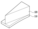
도 3a는 본 발명에 따른 가공용 팁의 제 1 실시예에 따른 가공용 팁의 사시도.3a is a perspective view of a machining tip according to a first embodiment of a machining tip according to the invention;
도 3b는 도 3a의 A-A'단면도.3B is a cross-sectional view along the line AA ′ of FIG. 3A;
도 3c는 제 1 실시예에 따른 가공용 팁으로 절삭되는 상태를 보이는 피삭재의 단면도. 3C is a cross-sectional view of the workpiece showing a state of being cut by the processing tip according to the first embodiment.
도 3d는 제 1 실시예에 따른 가공용 팁의 마모경과를 보이는 개념도.3d is a conceptual view showing the wear history of the machining tip according to the first embodiment.
도 3e는 제 1 실시예에 따른 가공용 팁이 샹크에 접합되는 상태를 보이는 정 면도. 3E is a front view showing a state in which the processing tip according to the first embodiment is bonded to the shank.
도 4a는 본 발명에 따른 가공용 팁의 제 2 실시예에 따른 가공용 팁의 사시도.4a is a perspective view of a machining tip according to a second embodiment of a machining tip according to the invention;
도 4b는 제 2 실시예에 따른 가공용 팁이 샹크에 접합되는 상태를 보이는 정면도. Figure 4b is a front view showing a state in which the processing tip according to the second embodiment is bonded to the shank.
도 5는 본 발명에 따른 가공용 팁의 제 3 실시예에 따른 가공용 팁의 사시도.5 is a perspective view of a machining tip according to a third embodiment of a machining tip according to the invention;
도 6a는 본 발명에 따른 가공용 팁의 제 4 실시예에 따른 가공용 팁의 사시도.6A is a perspective view of a machining tip according to a fourth embodiment of a machining tip in accordance with the present invention;
도 6b는 제 4 실시예에 따른 가공용 팁이 샹크에 접합되는 상태를 보이는 정면도. 6B is a front view showing a state where the machining tip according to the fourth embodiment is joined to the shank;
도 7a는 본 발명에 따른 가공용 팁의 제 5 실시예에 따른 가공용 팁의 사시도.7a is a perspective view of a machining tip according to a fifth embodiment of a machining tip in accordance with the present invention;
도 7b는 제 5 실시예에 따른 가공용 팁이 샹크에 접합되는 상태를 보이는 정면도. 7B is a front view showing a state where the machining tip according to the fifth embodiment is joined to the shank;
도 8a는 본 발명에 따른 가공용 팁의 제 6 실시예에 따른 가공용 팁의 사시도.8A is a perspective view of a machining tip according to a sixth embodiment of a machining tip in accordance with the present invention;
도 8b는 제 6 실시예에 따른 가공용 팁이 샹크에 접합되는 상태를 보이는 정면도. 8B is a front view showing a state in which a machining tip according to a sixth embodiment is joined to a shank;
도 9a는 본 발명에 따른 가공용 팁의 제 7 실시예에 따른 가공용 팁의 사시 도.9a is a perspective view of a machining tip according to a seventh embodiment of a machining tip in accordance with the present invention;
도 9b는 제 7 실시예에 따른 가공용 팁이 샹크에 접합되는 상태를 보이는 정면도. 9B is a front view showing a state in which a machining tip according to a seventh embodiment is joined to a shank;
도 10은 본 발명에 따른 가공용 팁의 제 8 실시예에 따른 가공용 팁의 평면도. 10 is a plan view of a machining tip according to an eighth embodiment of a machining tip according to the invention;
도 11a는 본 발명에 따른 가공용 팁의 제 9 실시예에 따른 가공용 팁의 사시도.11A is a perspective view of a machining tip according to a ninth embodiment of a machining tip according to the invention;
도 11b는 도 11a의 A-A'단면도.FIG. 11B is a sectional view taken along the line AA ′ of FIG. 11A;
도 12는 본 발명에 따른 가공용 팁의 제 10 실시예에 따른 가공용 팁의 사시도.12 is a perspective view of a machining tip according to a tenth embodiment of a machining tip in accordance with the present invention;
도 13은 본 발명에 따른 가공용 팁의 제 11 실시예에 따른 가공용 팁의 사시도.13 is a perspective view of a machining tip according to an eleventh embodiment of a machining tip according to the invention;
도 14a는 본 발명에 따른 가공용 팁의 제 12 실시예에 따른 가공용 팁의 사시도.14A is a perspective view of a machining tip according to a twelfth embodiment of a machining tip according to the invention;
도 14b는 본 발명의 제 12 실시예에 따른 가공용 팁이 샹크에 접합되는 상태를 보이는 사시도. 14B is a perspective view illustrating a state in which a machining tip is bonded to a shank according to a twelfth embodiment of the present invention;
도 14c는 본 발명의 제 12 실시예에 따른 가공용 팁으로 절삭되는 상태를 보이는 피삭재의 단면도이다. 14C is a cross-sectional view of a workpiece showing a state of being cut by a machining tip according to a twelfth embodiment of the present invention.
도 15는 본 발명의 제 13 실시예에 따른 가공용 팁이 샹크에 접합되는 상태를 보이는 사시도. 15 is a perspective view showing a state in which the machining tip is bonded to the shank according to a thirteenth embodiment of the present invention.
도 16a 및 16b는 본 발명에 따른 가공용 팁의 제 14 실시예에 따른 가공용 팁의 사시도.16a and 16b are perspective views of a machining tip according to a fourteenth embodiment of a machining tip according to the invention;
<도면의 주요부분에 대한 부호의 설명><Description of the symbols for the main parts of the drawings>
100 : 가공용 팁 110 : 제 1 연마부 100 processing tip 110: first polishing portion
115 : 절개홈 117 : 치합돌기 115: incision groove 117: engagement protrusion
119 : 홈 120 : 제 2 연마부 119: groove 120: second polishing unit
120a : 전단부 120b : 후단부 120a:
200 : 몸체200: body
본 발명은 가공를 절단하거나 천공하는 가공용 팁 및 상기 가공용 팁을 구비하는 공구에 관한 것으로, 보다 상세하게는 가공용 팁을 2개의 연마부로 구성하여 초기절삭불량을 방지하는 가공용 팁 및 가공공구에 관한 것이다. The present invention relates to a machining tip for cutting or punching a machining and a tool having the machining tip, and more particularly, to a machining tip and a processing tool for preventing an initial cutting failure by configuring the machining tip with two polishing parts.
다이아몬드는 경도가 가장 높은 재료로서 1950년대에 인조적으로 합성된 이후 여러가지 용도로 개발되어 왔으며, 중요한 용도처로서 각종 재료를 절삭하는 절삭공구에 적용되어 왔다.Diamond has the highest hardness and has been developed for various purposes since it was artificially synthesized in the 1950s, and has been applied to cutting tools for cutting various materials as important applications.
특히, 다이아몬드는 특히 비교적 경도가 강한 무기재료의 경우에도 뛰어난 절삭력을 보여, 예를들어, 화강석, 대리석, 벽돌, 내화벽돌, 콘크리트, 아스팔트 및 유리등의 가공재를 절삭하는 경우에도 널리 사용된다.In particular, diamond exhibits excellent cutting power even in the case of relatively hard inorganic materials, and is widely used for cutting materials such as granite, marble, brick, refractory brick, concrete, asphalt and glass, for example.
통상 다이아몬드를 채용한 공구는 다이아몬드 입자를 포함한 가공용 팁을 몸체등에 접합시킴으로써 구성되는데, 가공용 팁은 통상 금속재료에, 다이아몬드 입자 및 경도를 강화하기 위한 재료등을 포함하여 제작된다. Generally, a tool employing diamond is formed by joining a machining tip including diamond particles to a body or the like. The machining tip is usually made of a metal material, including diamond particles and materials for reinforcing hardness.
이 때, 가공용 팁은 디스크나 판형의 둘레에 접합되어 절단용으로 사용되기도 하고, 가공용 팁이 원통형 관의 둘레에 접합되어 천공용으로 사용되기도 한다. In this case, the processing tip may be joined to the circumference of the disk or plate to be used for cutting, and the processing tip may be joined to the circumference of the cylindrical tube to be used for drilling.
도 1a은 통상적인 톱형 절삭공구의 몸체 및 이에 접합된 가공용 팁의 형상을 보이는 사시도이다. 이에 따르면, 다이아몬드 입자를 포함하는 가공용 팁(20)이 몸체(샹크, 10)의 둘레를 따라 복수개로 접합되어 있고, 몸체(10)의 회전에 따라 둘레에 접합된 가공용 팁(20)이 피삭재를 절단하도록 구성된다. 몸체는 4인치에서 120인치까지 다양한 크기로 제작되고 있으며, 가공용 팁(20)은 몸체의 크기에 따라 직선 또는 곡선형상을 구비할 수 있다.(도 1a에는 직선("A") 및 곡선형("B")의 가공용 팁의 확대도가 도시되어 있다). Figure 1a is a perspective view showing the shape of the body of a conventional saw cutting tool and the machining tip bonded thereto. According to this, a plurality of
한편, 비용을 절감하기 위해 가공용 팁이 몸체에 접하는 기저부에는 다이아몬드가 포함되지 않는 접합부(20a) 형성되기도 한다. On the other hand, in order to reduce the cost, the bottom portion of the processing tip is in contact with the body may be formed with a joint 20a that does not contain diamond.
한편, 이러한 형태의 가공용 팁이 장착되는 공구로는 쏘 블레이드(Saw blade), 갱 쏘(gang saw), 체인 쏘(chain saw), 프레임 쏘(frame saw)등이 일반적으로 알려져 있다. On the other hand, as a tool on which a machining tip of this type is mounted, a saw blade, a gang saw, a chain saw, a frame saw, and the like are generally known.
도 1b는 통상적인 드릴형 절삭공구의 몸체(샹크) 및 이에 접합된 가공용 팁의 형상을 보이는 사시도로서, 이에 따르면, 가공용 팁(40)이 원통형의 몸체(30)의 둘레를 따라 복수개로 접합되어 있고, 원통형관(30)의 회전에 따라 가공용 팁(40) 이 피삭재를 드릴링하게 구성된다. 몸체(30)는 다양한 크기로 제작되고 있으며, 가공용 팁(20)은 몸체의 크기에 따라 직선 또는 곡선형상을 구비할 수 있다.(도 1b에는 곡선형("A") 및 직선형("B")의 가공용 팁(40)의 확대도가 도시되어 있다).FIG. 1B is a perspective view showing the shape of a body (shank) of a conventional drill-type cutting tool and a machining tip bonded thereto, whereby a plurality of
한편, 비용을 절감하기 위해 가공용 팁(40)이 몸체에 접하는 기저부에는 다이아몬드가 포함되지 않는 접합부(40a) 형성되기도 한다.On the other hand, in order to reduce the cost, the bottom portion of the
이러한 형태의 가공용 팁이 장착되는 공구로는 코어드릴(Core drill), 그라인딩 컵 휠(grinding cup wheel), 폴리싱 디스크 (polishing disc)등이 일반적으로 알려져 있다. As a tool equipped with this type of machining tip, a core drill, a grinding cup wheel, a polishing disc, and the like are generally known.
도 2a는 통상의 톱형 가공용 팁으로 절삭되는 상태를 보이는 피삭재의 단면도이다. 이에 따르면, 초기절삭시부터 후기절삭시까지 가공용 팁(20)이 피삭재에 닿는 부분의 폭이 동일하므로, 피삭재에 생기는 폭도 초기절삭시부터 후기절삭시까지 동일하게 된다. 이는, 도 2b에 도시된 바와 마찬가지로, 드릴형 가공용 팁의 경우도 동일하다. FIG. 2A is a cross-sectional view of a workpiece showing a state of being cut with a conventional saw-like machining tip. FIG. According to this, since the width of the portion where the
그러나, 어떠한 종래의 가공용 팁은 대체로 직육면체의 형상을 구비하고 있어, 절삭초기에도 절삭면에 면접촉을 하게 되어 초기에 가공용 팁이 피삭재에 용이하게 자리잡기 힘든 구조를 이루고 있었다. 이에 따라, 절삭공구를 사용할 경우, 진동, 소음, 깨짐, 이탈등의 문제점이 발생하고 있다. However, some conventional machining tips generally have the shape of a rectangular parallelepiped, and have a surface contact with the cutting surface even in the initial stage of cutting, so that the machining tip is difficult to be easily settled on the workpiece. Accordingly, when the cutting tool is used, problems such as vibration, noise, cracking, and separation occur.
또한, 초기 절삭 후에도 후기절삭시 가공용 팁이 절삭에 유리한 형태, 즉 외측이 나중에 마모되는 형태로 마모되지 못하는 문제점이 있다. In addition, even after the initial cutting, there is a problem that the processing tip during the later cutting does not wear in a form that is advantageous for cutting, that is, the outer side wears later.
본 발명은 상기한 문제점을 해결하기 위하여 안출된 것으로서, 본 발명의 목적은 초기절삭에 유리한 구조의 가공용 팁을 제공하는 데 있다. The present invention has been made to solve the above problems, an object of the present invention is to provide a machining tip of the structure advantageous for the initial cutting.
또한, 본 발명의 다른 목적은 후기절삭에 유리한 구조를 구비한 가공용 팁을 제공하는 데 있다. In addition, another object of the present invention is to provide a processing tip having a structure advantageous for post-cutting.
또한, 발명의 다른 목적은 초기절삭 및 후기절삭에 유리한 가공용 팁을 구비한 절삭공구를 제공하는 데 있다.Another object of the invention is to provide a cutting tool having a machining tip which is advantageous for early and late cutting.
본 발명의 일측면은 가공용 팁에 있어서, 제 1 높이로 형성되는 제 1 연마부; 및 상기 제 1 연마부에서 제 2 높이로 연장되며, 연마방향에 따라 피삭재에 먼저 접촉하는 전단부의 폭이 나중에 접촉하는 후단부의 폭보다 좁게 형성되는 제 2 연마부를 포함하는 것을 특징으로 한다.
이 때, 상기 제 2 연마부의 상기 전단부로부터 상기 후단부 사이의 폭이 점진적으로 넓어지는 것이 바람직하다.
또한, 상기 제 2 연마부의 전단부는 피삭재에 선접촉할 수 있다.
또한, 상기 제 2 연마부의 전단부는 피삭재에 점접촉할 수 있다.
또한, 상기 제 2 연마부의 상기 후단부의 끝단의 폭은 상기 제 1 연마부의 폭과 동일한 것이 바람직하다.
또한, 상기 제 2 연마부의 상기 전단부의 끝단은 상기 제 1 연마부의 끝단과 일치하는 것이 바람직하다.
또한, 상기 제 2 연마부의 상기 전단부의 끝단은 상기 제 1 연마부 폭의 중앙에 위치할 수 있다.
또한, 상기 제 2 연마부의 상기 전단부의 끝단은 상기 제 1 연마부 폭의 일측으로 치우쳐서 위치할 수 있다.
또한, 상기 제 2 연마부의 길이는 상기 제 1 연마부의 길이 보다 작거나 같은 것이 바람직하다.
또한, 상기 제 2 연마부의 상기 후단부는 상기 제 1 연마부의 후단 상부에 형성될 수 있다.
또한, 상기 제 2 연마부의 상기 후단부는 상기 제 1 연마부의 측면 상부에 형성될 수 있다.
또한, 상기 제 2 연마부의 상기 전단부는 상기 후단부보다 경도가 더 높은 것이 바람직하다.
또한, 상기 제 2 연마부의 상기 전단부는 상기 후단부보다 경도를 높이기 위한 연마재의 입자 농도가 더 높은 것이 바람직하다.
또한, 상기 연마재는 다이아몬드, SiC, WC, BN, 및 Al2O3로 구성되는 군에서 선택되는 하나 또는 하나 이상의 혼합물일 수 있다.
또한, 상기 제 2 연마부의 전단부로부터 상기 후단부 사이의 연마재의 집중도가 점진적으로 작아질 수 있다.
또한, 상기 제 2 연마부는 전단부로부터 후단부로 갈수록 연마재의 집중도가 낮아지는 적어도 2 이상의 영역을 가지고, 각 영역에서의 연마재의 집중도는 일정하게 구성할 수 있다.
또한, 상기 제 2 연마부는 연마재의 집중도가 다른 2개의 영역을 가지고, 전단부측의 제 1 영역의 연마재의 집중도는 0.9 carts/cc 내지 1.4 carts/cc이고, 후단부측의 제 2 영역의 연마재의 집중도는 0.6 carts/cc 내지 0.9 carts/cc인 것이 바람직하다.
또한, 상기 제 1 영역과 상기 제 2 영역의 길이비는 1 ~ 3 : 1 인 것이 바람직하다.
또한, 상기 제 2 연마부의 제 2 높이는 상기 제 1 연마부의 제 1 높이보다 긴 것이 바람직하다.
또한, 상기 제 2 연마부의 제 2 높이는 상기 제 1 연마부의 제 1 높이와 동일할 수 있다.
또한, 상기 제 2 연마부의 제 2 높이는 상기 제 1 연마부의 제 1 높이보다 짧을 수 있다.
또한, 상기 제 1 연마부는, 연마방향과 평행한 가상의 두 선을 따라, 중앙부의 B영역과 상기 B영역의 양측의 A영역 및 C영역으로 구획되고, 상기 A영역 및 상기 C영역에서의 연마재의 집중도가 상기 B영역에서의 연마재의 집중도보다 높게 구성할 수 있다.
또한, 상기 제 1 연마부의 기저에는 상기 제 A 영역, 상기 B 영역, 및 상기 C 영역의 연마재의 집중도보다 낮은 제 D 영역이 더 형성되는 것이 바람직하다.
또한, 상기 A영역, 상기 B영역 및 상기 C영역의 길이비는 1 ~ 2 : 1 : 1 ~ 2인 것이 바람직하다.
본 발명의 다른 측면은, 가공용 팁에 있어서, 접합하게 될 몸체 방향으로 돌출하는 적어도 치합돌기를 구비하고, 제 1 높이로 형성되는 제 1 연마부; 및 상기 제 1 연마부 상에 제 2 높이로 형성되며, 연마방향에 따라 피삭재에 먼저 접촉하는 전단부의 폭이 나중에 접촉하는 후단부의 폭보다 좁게 형성되는 제 2 연마부를 포함하는 것이 바람직하다.
또한, 상기 치합돌기는 상기 제 1 연마부의 중앙에 형성되는 것이 바람직하다.
또한, 상기 제 2 연마부의 상기 전단부는 상기 후단부보다 경도가 더 높은 것이 바람직하다.
또한, 상기 제 2 연마부는 연마재의 집중도가 다른 적어도 2 이상의 영역을 가지고, 전단부측에서 후단부 측으로 갈수록 연마재 집중도가 낮아지며, 각 영역에서의 연마재의 집중도는 일정한 것이 바람직하다.
또한, 상기 제 1 연마부는 연마방향과 평행한 가상의 두 선을 따라, 중앙부의 B영역과 상기 B영역의 양측의 A영역 및 C영역으로 구획되고, 상기 A영역 및 상기 C영역에서의 연마재의 집중도가 상기 B영역에서의 연마재의 집중도보다 높은 것이 바람직하다.
본 발명의 또 다른 측면은, 가공용 팁에 있어서, 제 1 높이로 형성되는 제 1 연마부; 및 상기 제 1 연마부 상에 제 2 높이로 형성되는 제 2 연마부를 포함하며, 상기 제 1 연마부 및 제 2 연마부에는 팁의 연마방향과 다른 방향으로 형성되는 적어도 하나 이상의 절개홈을 구비하고, 상기 절개홈에 의해 나누어지는 제 2 연마부의 각 부분은 연마방향에 따라 피삭재에 먼저 접촉하는 전단부의 폭이 나중에 접촉하는 후단부의 폭보다 좁게 형성되는 것을 특징으로 한다.
이 때, 상기 제 2 연마부의 상기 전단부는 상기 후단부보다 경도가 더 높은 것이 바람직하다.
또한, 상기 제 2 연마부는 연마재의 집중도가 다른 적어도 2 이상의 영역을 가지고, 전단부측에서 후단부 측으로 갈수록 연마재 집중도가 낮아지며, 각 영역에서의 연마재의 집중도는 일정한 것이 바람직하다.
또한, 상기 제 1 연마부는, 연마방향과 평행한 가상의 두 선을 따라, 중앙부의 A영역과 상기 A영역의 양측의 B영역 및 C영역으로 구획되고, 상기 B영역 및 상기 C영역에서의 연마재의 집중도가 상기 A영역에서의 연마재의 집중도보다 높은 것이 바람직하다. One side of the present invention is a machining tip, the first grinding portion formed to a first height; And a second polishing portion extending from the first polishing portion to a second height, the width of the front end portion contacting the workpiece first according to the polishing direction being smaller than the width of the rear end portion contacting later.
At this time, it is preferable that the width between the front end and the rear end of the second polishing portion gradually increases.
In addition, the front end portion of the second polishing portion may be in line contact with the workpiece.
In addition, the front end portion of the second polishing portion may be in point contact with the workpiece.
Further, the width of the end of the rear end of the second polishing portion is preferably the same as the width of the first polishing portion.
Further, it is preferable that the end of the front end of the second polishing part coincides with the end of the first polishing part.
In addition, an end of the front end portion of the second polishing portion may be located at the center of the first polishing portion width.
In addition, an end of the front end portion of the second polishing portion may be positioned to be biased toward one side of the first polishing portion width.
In addition, the length of the second polishing portion is preferably less than or equal to the length of the first polishing portion.
The rear end portion of the second polishing portion may be formed on an upper portion of the rear end portion of the first polishing portion.
In addition, the rear end of the second polishing unit may be formed on an upper side of the first polishing unit.
In addition, the front end portion of the second polishing portion is preferably higher in hardness than the rear end portion.
In addition, it is preferable that the front end portion of the second abrasive portion has a higher particle concentration of the abrasive for increasing hardness than the rear end portion.
In addition, the abrasive may be one or more mixtures selected from the group consisting of diamond, SiC, WC, BN, and Al 2 O 3 .
In addition, the concentration of the abrasive between the front end and the rear end of the second polishing part may be gradually reduced.
In addition, the second abrasive portion may have at least two or more regions in which the concentration of the abrasive is lowered from the front end to the rear end, and the concentration of the abrasive in each region may be constant.
In addition, the second abrasive portion has two regions with different concentrations of abrasive, and the concentration of the abrasive in the first region on the front end side is 0.9 carts / cc to 1.4 carts / cc, The concentration is preferably 0.6 carts / cc to 0.9 carts / cc.
In addition, the length ratio of the first region and the second region is preferably 1-3.
In addition, the second height of the second polishing unit is preferably longer than the first height of the first polishing unit.
In addition, the second height of the second polishing unit may be the same as the first height of the first polishing unit.
In addition, the second height of the second polishing unit may be shorter than the first height of the first polishing unit.
The first polishing portion is divided into regions A and C on both sides of the B region and the region B along the imaginary two lines parallel to the polishing direction, and the abrasive in the regions A and C. Concentration of can be configured to be higher than the concentration of the abrasive in the region B.
In addition, it is preferable that a D region having a concentration lower than the concentration of the abrasive in the A region, the B region, and the C region is further formed at the base of the first polishing portion.
In addition, the length ratio of the A region, the B region and the C region is preferably 1 to 2: 1: 1 to 2.
According to another aspect of the present invention, there is provided a machining tip comprising: a first polishing portion having at least a engagement protrusion protruding in a body direction to be joined and formed at a first height; And a second polishing portion formed on the first polishing portion at a second height and having a width of a front end portion contacting the workpiece first in a polishing direction narrower than a width of a rear end portion later contacting.
In addition, the engaging projection is preferably formed in the center of the first polishing portion.
In addition, the front end portion of the second polishing portion is preferably higher in hardness than the rear end portion.
In addition, it is preferable that the second abrasive portion has at least two or more regions having different concentrations of the abrasive, and the concentration of the abrasive decreases from the front end side to the rear end side, and the concentration of the abrasive in each region is constant.
Further, the first polishing portion is divided into regions A and C on both sides of the B region and the region B along the imaginary two lines parallel to the polishing direction. It is preferable that the concentration is higher than the concentration of the abrasive in the region B.
In still another aspect of the present invention, there is provided a machining tip comprising: a first polishing portion formed at a first height; And a second polishing portion formed at a second height on the first polishing portion, wherein the first polishing portion and the second polishing portion include at least one cutout groove formed in a direction different from the polishing direction of the tip. Each part of the second abrasive portion divided by the cutting groove is characterized in that the width of the front end portion contacting the workpiece first along the polishing direction is smaller than the width of the rear end portion contacting the workpiece.
At this time, the front end portion of the second polishing portion is preferably higher in hardness than the rear end portion.
In addition, it is preferable that the second abrasive portion has at least two or more regions having different concentrations of the abrasive, and the concentration of the abrasive decreases from the front end side to the rear end side, and the concentration of the abrasive in each region is constant.
The first polishing portion is divided into regions A of the central portion and regions B and C of both sides of the region A, along two imaginary lines parallel to the polishing direction, and the abrasive in the regions B and C. It is preferable that the concentration of is higher than the concentration of the abrasive in the region A.
본 발명의 또 다른 측면은 적어도 하나의 가공용 팁과, 상기 가공용 팁이 접합되는 몸체를 포함하여 구성되는 가공용 공구에 있어서, 상기 가공용 팁은 상기 몸체에 결합되며, 제 1 높이로 형성되는 제 1 연마부; 및 상기 제 1 연마부에서 제 2 높이로 연장되며, 연마방향에 따라 피삭재에 먼저 접촉하는 전단부의 폭이 나중에 접촉하는 후단부의 폭보다 좁게 형성되는 제 2 연마부를 포함하는 것을 특징으로 한다.
이 때, 상기 몸체는 디스크 또는 판형일 수 있다.
이 때, 상기 디스크 또는 판의 둘레를 따라 상기 가공용 팁이 접합되는 것이 바람직하다.
또한, 상기 몸체는 관(tube)형상일 수 있다.
이 때, 상기 관 단부의 둘레를 따라 상기 가공용 팁이 접합되는 것이 바람직하다. Another aspect of the present invention is a machining tool comprising at least one machining tip and a body to which the machining tip is joined, wherein the machining tip is coupled to the body and has a first polishing formed at a first height part; And a second polishing portion extending from the first polishing portion to a second height, the width of the front end portion contacting the workpiece first according to the polishing direction being smaller than the width of the rear end portion contacting later.
At this time, the body may be a disk or plate shape.
At this time, it is preferable that the processing tip is joined along the circumference of the disk or plate.
In addition, the body may be a tube (tube) shape.
At this time, it is preferable that the processing tip is joined along the circumference of the tube end.
이하에서는 도면을 참조하면서 본 발명의 일측면에 따른 실시예들을 설명하기로 하다. Hereinafter, with reference to the drawings will be described embodiments according to an aspect of the present invention.
도 3a는 톱형 절삭공구의 몸체(샹크)인 디스크에 부착되는 제 1 실시예에 따 른 가공용 팁 사시도가 도시되어 있다. 이에 따르면, 다이아몬드 입자가 포함된 가공용 팁(100)은 제 1 연마부(110)와 제 2 연마부(120)를 포함한다.3a shows a perspective view of a machining tip according to a first embodiment attached to a disk which is the body (shank) of a saw cutting tool. According to this, the
제 1 연마부(110)는 몸체(샹크)에 접합되는 부분으로 피삭재의 종류 및 재료에 따라서 소정의 높이로 구비된다. 제 1 연마부(110)는 통상의 가공용 팁과 마찬가지로 직육면체형등으로 제작될 수 있다. The
제 1 연마부(110)는 코발트(Co), 구리(Cu), 주석(Sn), 철(Fe), 아연(Zn), 니켈(Ni)등(열거에 제한되지 아니함)을 포함한 금속재료와, 경도를 보강하기 위한 다이아몬드, SiC, WC, BN, Al2O3등의 연마재를 포함할 수 있다. The
제 1 연마부(110)는 절삭이 진행되는 동안 절삭이 용이하게 이루어지게 하기 위하여 각 부위에 따라 재료의 조성을 다르게 할 수 있다. 예컨데, 절삭시 통상 양 측부는 경도가 높고, 중간에는 경도가 낮도록 형성할 수 있다.The
즉, 도 3a의 A-A'단면도로서 도 3b에는, 제 1 연마부가 가상의 선으로서 샹크에 부착되는 면의 세로방향으로 제 A 영역(A), 제 B 영역(B), 및 제 C 영역(C)으로 구획된다. 제 A 영역(A) 및 제 C 영역(C)은 양측부에 위치하는 영역이고, 제 B 영역(B)은 그 사이의 영역이다. That is, A-A 'cross-sectional view of Fig. 3A, in Fig. 3B, the first A region, the B region, and the C region in the longitudinal direction of the surface on which the first polishing portion is attached to the shank as an imaginary line. It is divided into (C). The A area | region A and C area | region C are area | regions located in both sides, and B area | region B is an area | region in between.
이는 마모도를 감안한 구성으로서, 피삭재에 의해 중앙이 먼저 마모될 경우에 가공용 팁이 좌우로 진동되지 않고, 안정되게 절삭할 수 있기 때문이다. 즉, 제 A 영역(A) 및 제 C 영역(C)은 가이드가 되고, 제 B 영역(B)은 트랙으로 하여 절삭될 수 있기 때문이다. 제 A 영역(A) 및 제 C 영역(C)의 경도를 높이기 위해서는 경 도를 보강하기 위한 다이아몬드, SiC, WC, BN, Al2O3등의 연마재를 제 B 영역(B)보다 더 많이 함유시킴으로써 가능하다. This is a configuration in consideration of the degree of wear, because when the center is first worn by the workpiece, the processing tip does not oscillate from side to side and can be stably cut. That is, since the A area | region A and the C area | region C become guides, and B area | region B can be cut | disconnected as a track | track. In order to increase the hardness of the A-th region A and the C-th region C, it is possible to contain more abrasives such as diamond, SiC, WC, BN, and Al 2 O 3 to reinforce the hardness than the B-region B. .
제 A 영역(A), 제 B 영역(B), 및 제 C 영역(C)의 길이(각각 a, b, c) 비율은 피삭재의 성등에 따라서 정해질 수 있다. 바람직하게는, a : b : c는 1 ~ 2: 1 : 1 ~ 2 등으로 구성할 수 있다. The ratio of the lengths (a, b, c) of the A-th region A, the B-th region B, and the C-th region C may be determined according to the quality of the workpiece. Preferably, a: b: c can be comprised from 1-2, 1: 1: 1, etc.
제 2 연마부(120)는 초기절삭을 용이하게 하기 위해 제 1 연마부(110)의 상부에 접합되는 부분으로, 연마시에 피삭재에 먼저 접촉하는 전단부(120a)의 폭이 나중에 접촉하는 후단부(120b)의 폭보다 좁게 형성된다. 즉, 피삭재에 먼저 접촉하는 초기 접촉면적이 좁을 수록 초기 절삭시 진동 및 이로인한 이탈이 발생하지 않는데, 전단부를 후단부의 폭보다 좁게 형성함으로써 초기에 가공용 팁(120)이 피삭재에 용이하게 자리잡게 할 수 있다.The second
전단부(120a)와 후단부(120b)의 폭은 다양하게 변형가능하나 본 실시예에서는 전단부(120a)의 끝점을 정점으로하여 점전적으로 넓어지면서 후단부(120b)는 제 1 연마부(110)의 폭과 동일하게 형성되고 있다. The widths of the
특히, 도시된 바와 같이 전단부(120a)의 끝점을 정점으로 할 경우, 가공용 팁(100)와 피삭재는 종래의 면접촉 대신 선접촉 또는 점접촉을 이룸으로써 진동 및 이탈을 보다 감소시킬 수 있다. In particular, when the end point of the front end portion (120a) as shown in the apex, the
제 2 연마부(120)의 재질 또한 제 1 연마부와 마찬가지로 코발트(Co), 구리(Cu), 주석(Sn), 철(Fe), 아연(Zn), 니켈(Ni)등을 포함한 금속재료와, 경도를 보강 하기 위한 다이아몬드, SiC, WC, BN, Al2O3등의 연마재를 더 포함하나, 그 조성은 제 1 연마부와 달리하거나 동일하게 구성할 수 있다. Like the first polishing unit, the material of the
이 때, 제 2 연마부(120)의 전단부(120a)와 후단부(120b)는 서로 다른 경도를 가지게 구성할 수 있다. 일반적으로 초기 절삭시 전단부(120a)가 보다 많은 마찰을 받으므로, 전단부(120a)의 경도를 보다 높일 필요가 있으며, 피삭재의 성질등을 고려하여 다양하게 경도를 조절할 수 있다. 경도 조절은 전술한 경도가 높은 연마재인 다이아몬드, SiC, WC, BN, Al2O3의 농도를 높임으로써 가능할 것이다. In this case, the
또한, 제 2 연마부에서 연마재의 집중도는 피삭재의 성질, 예를 들면 석재의 경우 등급, 산지, 콘크리트의 경우 압축강도, 양생기간이나 절단기구의 마력수 등에 따라서 조절이 가능할 것이다. 일예로 제 2 연마부(120)를 두 구역으로 크게 나뉘도록 연마재의 집중도를 조절할 수 있다. 즉, 제 2 연마부(120)의 전단부측의 제 1 구역의 연마재의 집중도는 0.9 carts/cc 내지 1.4 carts/cc로 구성하고, 상기 제 1 연마부(120)의 후단부측의 제 2 구역의 연마재의 집중도는 0.6 carts/cc 내지 0.9 carts/cc 로 구성할 수 있다. 상기 범위 초과하는 경우, 절삭불량이 생길 수 있고, 상기 범위 미만인 경우 마모율이 높아지기 때문이다. In addition, the concentration of the abrasive in the second abrasive portion may be adjusted according to the properties of the workpiece, for example, grades, production sites, compressive strength in the case of concrete, curing period or number of horsepower of the cutting tool. For example, the concentration of the abrasive may be adjusted to divide the second abrasive 120 into two zones. That is, the concentration of the abrasive in the first zone on the front end side of the
이 때, 제 1 구역 및 제 2 구역의 길이 비율도 적절한 수준에서 조절할 수 있을 것이다. 예컨데, 제 1 구역의 길이 : 제 2 구역의 길이는 1 ~ 3 : 1로 구성할 수 있다.At this time, the length ratio of the first zone and the second zone may also be adjusted at an appropriate level. For example, the length of the first zone: the length of the second zone may be configured to 1-3.
또한, 전단부(120a)에서 후단부(120b)까지의 제 2 연마부(120)를 3개 이상의 영역으로 나누어 연마재의 집중도를 점차 낮추도록 구성하는 것이나, 영역의 구획없이 점진적으로 전단부(120a)로부터 후단부(20b)까지 집중도를 낮추는 것도 가능할 것이다. In addition, the second
한편, 본 제 1 실시예에서 제 1 연마부의 높이(f)는 제 2 연마부(g)의 높이보다 크게 표시되어 있으나, 이에 제한되지 않고 각 높이는 경도와 마찬가지로 피삭재의 성질 및 각 연마부의 경도등에 따라 고려되어야 할 것이다. 예컨데, 제 1 연마부의 높이(f)가 작아지고, 제 2 연마부의 높이(g)의 길이가 길어질수록 제 A 영역(A) 및 제 C 영역(C)의 연마재의 양은 급수적으로 증가해야 할 것이다. On the other hand, in the first embodiment, the height f of the first polishing portion is larger than the height of the second polishing portion g. However, the height f is not limited thereto, and the height is similar to the hardness of the workpiece and the hardness of each polishing portion. Should be considered accordingly. For example, as the height f of the first abrasive portion becomes smaller and the length of the height g of the second abrasive portion becomes longer, the amount of the abrasive in the A regions A and C regions C should increase in water. .
또한, 제 1 연마부와 제 2 연마부의 길이는 동일하거나 동일하지 않을 수 있으며(제 2 연마부의 길이가 제 1 연마부의 길이보다 작을 수 있음), 제 2 연마부의 형상은 다양하게 변형가능하다. 특히, 제 2 연마부의 전단의 끝점은 제 1 연마부의 폭의 중앙에 위치하거나 양측에 치우쳐서 위치될 수 있다. Also, the length of the first polishing portion and the second polishing portion may or may not be the same (the length of the second polishing portion may be smaller than the length of the first polishing portion), and the shape of the second polishing portion may be variously modified. In particular, the end point of the front end of the second polishing part may be located at the center of the width of the first polishing part or at both sides.
도 3c는 제 1 실시예에 따른 가공용 팁으로 절삭되는 상태를 보이는 피삭재의 단면도이다. 제 1 실시예에 따른 가공용 팁(100)으로 절삭할 경우에는, 초기절삭시 제 2 연마부의 전단부가 닿는 부분이 먼저 절삭되고, 점진적으로 제 2 연마부의 후단부가 닿는 부분이 커지면서 후기절삭시 가공용 팁의 전체 폭만큼 피삭재가 절삭되는 것을 볼수 있다.3C is a cross-sectional view of the workpiece showing a state of being cut by the machining tip according to the first embodiment. In the case of cutting with the
도 3d는 제 1 실시예에 따른 가공용 팁의 마모경과를 보이는 개념도로서, 초기 절삭시에는 제 1 연마부(110)상의 제 2 연마부(120)의 전단이 먼저 마모되면서 제 2 연마부(120)가 점차적으로 모두 마모되고, 이후 제 1 연마부가 마모된다. 즉, 제 2 연마부는 피삭재의 초기절삭에 관여한다는 것을 알 수 있다.FIG. 3D is a conceptual view showing a wear history of a machining tip according to the first embodiment. In the initial cutting, the shear of the
이후, 제 1 연마부도 경도가 약한 부분부터 마모될 것이다. 예컨데, B영역의 경도가 약한 경우 B형역부터 마모되고, A 및 C영역이 나중에 마모될 것이다. Thereafter, the first abrasive portion will also be worn from the weak hardness portion. For example, if the hardness of region B is weak, it will wear out from the form B region and regions A and C will wear out later.
한편, 도 3e는 제 1 실시예에 따른 가공용 팁이 샹크에 접합되는 상태를 보이는 정면도이다. 이에 따르면, 샹크(200)의 둘레를 따라 소정간격으로 이격되는 슬롯(210)을 구비하고 있고, 각 가공용 팁(100)은 슬롯(210)사이에 부착된다. 이 때, 가공용 팁(100)과 샹크(200)와의 접합은 용접법 등으로 이루어 질 수 있다. 본 실시예에 있어서, 슬롯(210)의 형상에는 제한되지 않는다.On the other hand, Figure 3e is a front view showing a state in which the machining tip is bonded to the shank according to the first embodiment. According to this, there is provided a
이하의 실시예에서는 제 1 실시예와 동일한 구성요소에 대해서는 동일한 부호를 부여하여 설명한다. In the following embodiments, the same components as in the first embodiment will be described with the same reference numerals.
도 4a는 톱형 절삭공구에 부착되는 제 2 실시예에 따른 가공용 팁의 사시도가 도시되어 있다. 제 2 실시예는 제 1 실시예와 달리 제 1 연마부(110)의 높이가 제 2 연마부(120)의 높이보다 작다는 것을 제외하고는 동일하므로 이에 대한 상세한 설명은 생략한다. Figure 4a shows a perspective view of a machining tip according to a second embodiment attached to a saw cutting tool. Unlike the first embodiment, the second embodiment is the same except that the height of the
한편, 도 4b는 제 2 실시예에 따른 가공용 팁이 샹크에 접합되는 상태를 보이는 정면도이다. 이에 따르면, 샹크(200)는 둘레를 따라 소정간격으로 이격되는 슬롯(210)을 구비하고 있고, 각 가공용 팁은 슬롯(210)사이에 부착된다. On the other hand, Figure 4b is a front view showing a state in which the processing tip according to the second embodiment is bonded to the shank. According to this, the
도 5는 톱형 절삭공구에 부착되는 제 3 실시예에 따른 가공용 팁의 사시도가 도시되어 있다. 제 3 실시예는 제 1 실시예와 달리 가공용 팁(100)이 직선형이 아닌 곡선형이라는 점을 제외하고는 동일하므로 이에 대한 상세한 설명은 생략한다. 5 shows a perspective view of a machining tip according to a third embodiment attached to a saw cutting tool. Unlike the first embodiment, the third embodiment is the same except that the
도 6a는 톱형 절삭공구에 부착되는 제 4 실시예에 따른 가공용 팁 사시도가 도시되어 있다. 제 4 실시예는 제 1 실시예에서 가공용 팁(100)의 일위치에 가공용 팁(100)을 연마방향과 다른 방향, 예컨데 가로방향, 으로 구획하여, 팁을 두 부분으로 구획하는 절개홈(115)이 1 개 형성되어 있다. 절개홈(115)은 절삭시 절삭속도를 높여주고, 절삭소음을 감소시키기 위해 형성한다. 6A shows a perspective view of a machining tip according to a fourth embodiment attached to a saw cutting tool. In the fourth embodiment, the cutting
절개홈(115)은 일예로 제 2 연마부(110) 및 제 1 연마부(120)의 상부를 절개하도록 형성할 수 있다.For example, the cutting
본 실시예에서 제 2 연마부(120)는 제 1 연마부(110)가 절개홈(115)에 의해 절개된 각각의 구역에서 전단부의 폭이 후단부의 폭보다 좁게 각각 형성될 수 있다. 또한, 도시된 것과는 달리, 각 영역상에 각각 형성된 제 2 절개홈들은 서로 다른 형상일 수도 있다.In the present embodiment, the
한편, 도 6b는 제 4 실시예에 따른 가공용 팁이 샹크에 접합되는 상태를 보이는 정면도이다. 이에 따르면, 샹크(200)는 둘레를 따라 소정간격으로 이격되는 슬롯(210)을 구비하고 있고, 절개홈(115)을 구비한 각 가공용 팁(100)은 슬롯(210)사이에 부착된다. On the other hand, Figure 6b is a front view showing a state in which the processing tip according to the fourth embodiment is bonded to the shank. According to this, the
도 7a는 톱형 절삭공구에 부착되는 제 5 실시예에 따른 가공용 팁의 사시도가 도시되어 있다. 제 5 실시예는 제 4 실시예에서 가공용 팁(100)의 일위치에 가공용 팁을 회전방향의 가로방향으로 구획하는 절개홈(115b)이 하나 더 형성되어 2 개의 절개홈(115a, 115b)이 형성된다. 이로써, 가공용 팁(100)에 형성되는 절개홈(115b)의 형성갯수는 본 실시예에서 제한되지 않음을 당업자는 인식할 것이다. 7A shows a perspective view of a machining tip according to a fifth embodiment attached to a saw cutting tool. In the fifth embodiment, in the fourth embodiment, one
한편, 도 7b는 제 5 실시예에 따른 가공용 팁이 샹크에 접합되는 상태를 보이는 정면도이다. 이에 따르면, 샹크(200)는 둘레를 따라 소정간격으로 이격되는 슬롯(210)을 구비하고 있고, 2개의 절개홈(115a, 115b)를 구비한 각 가공용 팁(120)은 슬롯(210)들 사이의 위치에 부착된다. On the other hand, Figure 7b is a front view showing a state in which the processing tip according to the fifth embodiment is bonded to the shank. According to this, the
도 8a는 톱형 절삭공구에 부착되는 제 6 실시예에 따른 가공용 팁의 사시도가 도시되어 있다. 제 6 실시예는 제 4 실시예에서 가공용 팁(100)은 샹크(200)에 치합되는 치합돌기(117)를 더 구비하고 있고, 샹크(200)는 치합돌기(117)와 대향하는 형상의 치합홈(215)을 구비하고 있다. 치합돌기(117)와 치합홈(215)에 부착됨으로써 가공용 팁은 샹크(200)에 용이하게 위치 설정되며, 가공용 팁(100)과 샹크(200)사이의 접합력이 높아지고, 절개홈(115) 주변에 크랙을 발생시키는 응력을 분산시킨다. 이 때, 치합돌기(117)는 가공용 팁(100)의 제 1 연마부(110) 중앙에 형성될 수 있다.8A shows a perspective view of a machining tip according to a sixth embodiment attached to a saw cutting tool. In the sixth embodiment, the
한편, 도 8b는 제 6 실시예에 따른 가공용 팁이 샹크에 접합되는 상태를 보이는 정면도이다. 이에 따르면, 샹크(200)는 둘레를 따라 소정간격으로 이격되는 슬롯(210)을 구비하고 있고, 절개홈(115)를 구비한 각 가공용 팁(100)은 슬롯들 사이의 위치에 부착된다. 또한, 가공용 팁(100)의 치합돌기(117)는 샹크측에 형성된 치합홈(215)에 삽입되어 샹크(200)에 결합된다.8B is a front view showing a state in which a machining tip according to a sixth embodiment is bonded to a shank. According to this, the
도 9a는 톱형 절삭공구에 부착되는 제 7 실시예에 따른 가공용 팁의 사시도가 도시되어 있다. 제 7 실시예는 제 5 실시예에서의 가공용 팁(100)이 샹크(200)에 치합되는 치합돌기(117)를 더 구비하고 있고, 샹크(200)는 치합돌기(117)와 대향하는 형상의 치합홈(215)을 구비하고 있다. 치합돌기(117)와 치합홈(215)에 부착됨으로써 가공용 팁은 샹크(200)에 용이하게 위치 설정되며, 가공용 팁(100)과 샹 크(200)사이의 접합력이 높아진다. 이 때, 치합돌기의 위치와 길이는 다양하게 형성될 수 있고, 본 실시예의 형태에 제한되지 않는다.9A shows a perspective view of a machining tip according to a seventh embodiment attached to a saw cutting tool. The seventh embodiment further includes a engaging
한편, 도 9b는 제 7 실시예에 따른 가공용 팁이 샹크에 접합되는 상태를 보이는 정면도이다. 이에 따르면, 샹크(200)는 둘레를 따라 소정간격으로 이격되는 슬롯(210)을 구비하고 있고, 2개의 절개홈(115a, 115b)을 구비한 각 가공용 팁(100)은 슬롯(210)들 사이의 위치에 부착된다. 또한, 가공용 팁(210)의 치합돌기(117)는 샹크측에 형성된 치합홈(215)에 삽입되어 샹크(200)에 결합된다.On the other hand, Figure 9b is a front view showing a state in which the machining tip is bonded to the shank according to the seventh embodiment. According to this, the
도 10은 톱형 절삭공구에 부착되는 제 8 실시예에 따른 가공용 팁 평면도가 도시되어 있다. 제 8 실시예는 제 1 실시예와 달리 제 2 연마부(120)의 후단부가 제 1 연마부(110)의 후단 상부에 위치하고, 측면 상부에 위치하고 있다. 이로써, 당업자는 제 2 연마부의 형상이 본 실시예에 제한되지 않음을 이해할 것이다.10 shows a top view of a machining tip in accordance with an eighth embodiment attached to a saw cutting tool. In the eighth embodiment, unlike the first embodiment, the rear end of the
도 11a는 톱형 절삭공구에 부착되는 제 9 실시예에 따른 가공용 팁의 사시도가 도시되어 있다. 제 9 실시예는 제 1 실시예에서의 가공용 팁(100)이 샹크(200)에 치합되는 기저부에 연마재가 포함되지 않거나, 다른 전술한 A, B 및 C영역에 비해 연마재의 함량이 작은 접합부(D;110a)를 구비하고 있다. 접합부(D;110a)를 형성함으로써 직접적으로 절삭에 관여하지 않는 기저부에 고가의 다이아몬드가 낭비되는 것을 절감할 수 있다. 11a shows a perspective view of a machining tip according to a ninth embodiment attached to a saw cutting tool. The ninth embodiment does not include the abrasive at the base portion where the
즉, 도 11a의 A-A'단면도로서 도 11b에는 제 1 연마부(110)의 기저부에는 다이아몬드등의 연마재가 포함되지 않는 접합부가 형성되어 있다. In other words, a cross-sectional view taken along the line A-A 'in Fig. 11A, in Fig. 11B, a joint is formed in the base of the first
도 12는 톱형 절삭공구에 부착되는 제 10 실시예에 따른 가공용 팁 사시도가 도시되어 있다. 제 10 실시예는 제 1 실시예와 달리 제 2 연마부(120)의 전단부(120a)에서 후단부(120b)로 가면서 폭이 급격히 증가하여 전단의 일정길이(l)를 제외하고는 제 1 연마부(110)의 폭과 제 2 연마부(120)의 폭이 일정하게 형성된다. 이 때, 길이(l)은 피삭재의 성질에 맞게 변경될 수 있을 것이다. Figure 12 shows a perspective view of a machining tip according to a tenth embodiment attached to a saw cutting tool. Unlike the first embodiment, the tenth embodiment rapidly increases in width from the
도 13은 톱형 절삭공구에 부착되는 제 11 실시예에 따른 가공용 팁 사시도가 도시되어 있다. 제 11 실시예는 제 1 실시예와 달리 제 2 연마부(120)가 전단부(120a)에서 후단부(120b)로 가면서 유선형 형상을 이루고 있다. 이로써, 당업자는 제 2 연마부의 형상이 본 실시예에 제한되지 않음을 이해할 것이다. 13 shows a perspective view of a machining tip in accordance with an eleventh embodiment attached to a saw cutting tool. Unlike the first embodiment, the eleventh embodiment has a streamlined shape as the
도 14a는 드릴형 절삭공구에 부착되는 제 12 실시예에 따른 가공용 팁의 사시도가 도시되어 있다. 제 12 실시예는 드릴형 절삭공구에 접합된다는 점을 제외하고는 제 1 실시예와 동일한 형상의 가공용 팁으로 구성할 수 있으므로 이에 대한 자세한 설명은 생략한다. 14A shows a perspective view of a machining tip according to a twelfth embodiment attached to a drilled cutting tool. The twelfth embodiment can be configured as a machining tip having the same shape as that of the first embodiment except that it is joined to a drill-type cutting tool, so a detailed description thereof will be omitted.
한편, 도 14b는 제 12 실시예에 따른 가공용 팁이 샹크에 접합되는 상태를 보이는 사시도이다. 이에 따르면, 드릴형 절삭공구에서 샹크(200)는 통상 튜브형태임)의 둘레를 따라 가공용 팁(100)이 부착된다. 이 때, 가공용 팁(100)과 샹크(200)와의 접합은 용접법등으로 이루어 질 수 있으며, 부착되는 가공용 팁의 수는 드릴의 크기 및 용도에 따라 달라질 수 있다. On the other hand, Figure 14b is a perspective view showing a state that the machining tip is bonded to the shank according to the twelfth embodiment. According to this, the
도 14c는 제 12 실시예에 따른 가공용 팁으로 절삭되는 상태를 보이는 피삭재의 단면도이다. 이에 따르면, 초기절삭시 제 2 연마부(120)의 전단부(120a)가 닿는 부분이 먼저 절삭되고, 점진적으로 제 2 연마부(120)의 후단부(120b)가 닿는 부 분이 커지면서 후기절삭시 가공용 팁(100)의 전체 폭만큼 피삭재가 절삭되는 것을 확인할 수 있다.FIG. 14C is a cross-sectional view of a workpiece showing a state of being cut by a machining tip according to a twelfth embodiment. FIG. According to this, during the initial cutting, the portion where the
도 15는 드릴형 절삭공구에 부착되는 제 13 실시예에 따른 가공용 팁의 사시도가 도시되어 있다. 제 13 실시예는 가공용 팁(100)의 적어도 일면에 가공용 팁에 굴곡을 주기위한 홈(119)이 형성되어 있다. 이 때, 홈(119)은 소음을 저감시키고, 절삭력을 향상시키는 기능을 가진다. 이 점을 제외하고는 제 1 실시예와 동일한 형상의 가공용 팁으로 구성할 수 있으므로 이에 대한 자세한 설명은 생략한다Fig. 15 shows a perspective view of a machining tip according to a thirteenth embodiment attached to a drilled cutting tool. In the thirteenth embodiment, a
도 16a 및 도 16b는 드릴형 절삭공구에 부착되는 제 14 실시예에 따른 가공용 팁의 사시도가 도시되어 있다. 제 14 실시예는 팁의 폭이 좁은 경우, 제 2 연마부의 제조를 용이하게 하기 위해, 제 2 연마부의 전단부가 제 1 연마부의 중앙이 아니라, 일측으로 치우치면서 위치되도록 구성된다. 이외에는 전술한 다른 실시예와 동일하므로 자세한 설명은 생략한다.16A and 16B show a perspective view of a machining tip according to a fourteenth embodiment attached to a drilled cutting tool. The fourteenth embodiment is configured such that when the tip is narrow, the front end portion of the second abrasive portion is positioned to one side, not to the center of the first abrasive portion, to facilitate the manufacture of the second abrasive portion. Other details are the same as in the other embodiments described above, so detailed description thereof will be omitted.
또한, 드릴형 절삭공구의 몸체에 접합되는 가공용 팁의 경우에도 전술한 톱형 절삭공구를 설명한 제 3 실시예 내지 제 11 실시예에서와 같이 동일한 방식으로 당업자에게 응용될 수 있을 것이므로, 이에 대한 상세한 설명은 생략한다.Further, in the case of the machining tip bonded to the body of the drill-type cutting tool, the same may be applied to those skilled in the art in the same manner as in the third to eleventh embodiments of the saw-type cutting tool described above, and thus, a detailed description thereof Is omitted.
즉, 전술한 가공용 팁들이 부착되는 절삭공구의 몸체는 다양한 형태 예컨데 디스크, 튜브등이 될 수 있으며, 상기 몸체는 회전축등의 동력전달 수단이 구비될 것이다. 본 발명에 따른 가공용 팁은 몸체의 형상에 따라 제한되지 않으며, 이러한 절삭공구들의 예로서는 전술한 바와 같이 쏘 블레이드(Saw blade), 갱 쏘(gang saw), 체인 쏘(chain saw), 프레임 쏘(frame saw)코어드릴(Core drill), 그라인딩 컵 휠(grinding cup wheel), 폴리싱 디스크 (polishing disc)등이 있을 수 있으며, 당업자는 이들 공구에 본 실시예에 따른 가공용 팁을 용접법을 이용하여 용이하게 부착할 수 있을 것이다. That is, the body of the cutting tool to which the above-described processing tips are attached may be in various forms, for example, discs, tubes, etc. The body may be provided with a power transmission means such as a rotating shaft. The machining tip according to the invention is not limited to the shape of the body, and examples of such cutting tools are saw blades, gang saws, chain saws, frame saws as described above. saw core drill, grinding cup wheel, polishing disc, etc., and those skilled in the art can easily attach the machining tip according to the present embodiment to these tools by welding. You can do it.
본 발명은 상기 실시예들을 기준으로 주로 설명되어졌으나, 발명의 요지와 범위를 벗어나지 않고 많은 다른 가능한 수정과 변형이 이루어질 수 있다. 예컨데, 가공용 팁의 구체적인 형상의 변경, 가공용 팁의 전단부의 각의 특정, 절개홈의 형성위치 변경, 제 1 연마부와 제 2 연마부의 재료의 특정, 제 1 연마부의 형상의 변경등은 당업자가 용이하게 변형할 수 있는 변형에 속할 것이다. 또한, 구체적인 실시예로 기재되지는 않았으나, 본 명세서에서 제시된 실시예들을 조합하는 것은 당업자에게 용이한 변형일 것이다. Although the present invention has been described primarily with reference to the above embodiments, many other possible modifications and variations can be made without departing from the spirit and scope of the invention. For example, those skilled in the art can change the specific shape of the machining tip, specify the angle of the front end of the machining tip, change the formation position of the cutting groove, specify the material of the first and second polishing parts, and change the shape of the first polishing part. It will belong to a variant that can be easily modified. In addition, although not described in detail, the combination of the embodiments presented herein will be an easy variation for those skilled in the art.
본 발명에 따른 가공용 팁 및 이를 장착한 절삭공구는 팁을 제 1 연마부 및 제 1 연마부 상에 형성되는 전단이 후단보다 폭이 좁은 제 2 연마부를 구비하여, 상기 제 2 연마부를 피삭재의 성질, 기계강성조건, 가공재의 종류에 따라 다양하게 폭, 길이, 높이, 및 연마재의 집중도를 변형시킴으로써, 초기절삭이 가공용 팁이 이탈되거나, 진동됨 없이 이루어지게 하는 효과가 있다.The processing tip and the cutting tool equipped with the same according to the present invention include a tip having a first abrasive portion and a second abrasive portion having a narrower width than a rear end of a shear formed on the first abrasive portion, so that the second abrasive portion has a property of a workpiece. By varying the width, length, height, and concentration of the abrasive in a variety of ways depending on the mechanical stiffness conditions and the type of workpiece, the initial cutting can be effected without leaving the machining tip off or vibrating.
또한, 후기절삭시에도 제 1 연마부를 소정의 영역으로 나누어, 경도를 달리함으로써 보다 용이하게 절삭이 이루어질게 하는 효과가 있다. In addition, even during post-cutting, the first polishing part is divided into predetermined areas, thereby making cutting easier by changing hardness.
전술한 발명에 대한 권리범위는 이하의 청구범위에서 정해지는 것으로써, 명세서 본문의 기재에 구속되지 않으며, 청구범위의 균등범위에 속하는 변형과 변경 은 모두 본 발명의 범위에 속할 것이다. The scope of the above-described invention is defined in the following claims, not bound by the description in the text of the specification, all modifications and variations belonging to the equivalent scope of the claims will fall within the scope of the invention.
Claims (38)
Priority Applications (2)
| Application Number | Priority Date | Filing Date | Title |
|---|---|---|---|
| KR1020060025059A KR100725164B1 (en) | 2006-03-17 | 2006-03-17 | Machining Tips and Machining Tools Using the Same |
| US11/600,157 US20070227521A1 (en) | 2006-03-17 | 2006-11-16 | Processing tips and tools using the same |
Applications Claiming Priority (1)
| Application Number | Priority Date | Filing Date | Title |
|---|---|---|---|
| KR1020060025059A KR100725164B1 (en) | 2006-03-17 | 2006-03-17 | Machining Tips and Machining Tools Using the Same |
Publications (1)
| Publication Number | Publication Date |
|---|---|
| KR100725164B1 true KR100725164B1 (en) | 2007-06-07 |
Family
ID=38358393
Family Applications (1)
| Application Number | Title | Priority Date | Filing Date |
|---|---|---|---|
| KR1020060025059A Expired - Fee Related KR100725164B1 (en) | 2006-03-17 | 2006-03-17 | Machining Tips and Machining Tools Using the Same |
Country Status (2)
| Country | Link |
|---|---|
| US (1) | US20070227521A1 (en) |
| KR (1) | KR100725164B1 (en) |
Cited By (1)
| Publication number | Priority date | Publication date | Assignee | Title |
|---|---|---|---|---|
| KR101963584B1 (en) * | 2018-11-01 | 2019-03-29 | (주)태성사 | Core bit for strong rock |
Family Cites Families (18)
| Publication number | Priority date | Publication date | Assignee | Title |
|---|---|---|---|---|
| US1156166A (en) * | 1912-06-20 | 1915-10-12 | Willard F Meyers | Stone-saw. |
| US3072470A (en) * | 1959-12-01 | 1963-01-08 | Diamond Tool Associates | Method of making a cutting apparatus |
| US3371452A (en) * | 1965-02-08 | 1968-03-05 | Christensen Diamond Prod Co | Diamond saw or milling blades |
| US4407263A (en) * | 1981-03-27 | 1983-10-04 | Diamond Giken Co., Ltd. | Cutting blade |
| JPS5912563U (en) * | 1982-07-13 | 1984-01-26 | 旭ダイヤモンド工業株式会社 | Tip mounting structure of diamond cutting wheel |
| DE3712953A1 (en) * | 1987-04-16 | 1988-11-03 | Rudolf Buettner | CUTTING TOOL |
| US5311705A (en) * | 1992-03-06 | 1994-05-17 | Zuzelo Edward A | Contoured cutting tool |
| CA2243694C (en) * | 1996-03-15 | 2003-04-29 | Norton Company | Metal single layer abrasive cutting tool having a contoured cutting surface |
| US7124753B2 (en) * | 1997-04-04 | 2006-10-24 | Chien-Min Sung | Brazed diamond tools and methods for making the same |
| US6039641A (en) * | 1997-04-04 | 2000-03-21 | Sung; Chien-Min | Brazed diamond tools by infiltration |
| JP2001205566A (en) * | 2000-01-26 | 2001-07-31 | Noritake Co Ltd | Resin-impregnated vitrified grinding wheel and its manufacturing method |
| US6632131B1 (en) * | 2000-02-03 | 2003-10-14 | Terry L. Buchholz | Combination rotary cutting and sanding blade |
| DE10005064A1 (en) * | 2000-02-04 | 2001-08-23 | Siegfried Goelz Gmbh & Co | Sintered metal bonded segments with abrasive action are made up of segment modules with from front to back in direction of movement alternating concentrations of hard material particles |
| US7234550B2 (en) * | 2003-02-12 | 2007-06-26 | Smith International, Inc. | Bits and cutting structures |
| KR100420933B1 (en) * | 2003-03-06 | 2004-03-02 | 이화다이아몬드공업 주식회사 | Gear type machining tip and tool attaching the same thereon |
| DE102004010781B4 (en) * | 2004-03-05 | 2014-09-04 | Dolmar Gmbh | Concrete saw chain and method of making a saw chain |
| KR100492854B1 (en) * | 2004-09-15 | 2005-06-02 | 세원테크 주식회사 | Grinding wheel |
| WO2006054674A1 (en) * | 2004-11-19 | 2006-05-26 | Toyoda Van Moppes Ltd. | Grinding wheel |
-
2006
- 2006-03-17 KR KR1020060025059A patent/KR100725164B1/en not_active Expired - Fee Related
- 2006-11-16 US US11/600,157 patent/US20070227521A1/en not_active Abandoned
Non-Patent Citations (1)
| Title |
|---|
| 기재불비로 의견제출통지 |
Cited By (1)
| Publication number | Priority date | Publication date | Assignee | Title |
|---|---|---|---|---|
| KR101963584B1 (en) * | 2018-11-01 | 2019-03-29 | (주)태성사 | Core bit for strong rock |
Also Published As
| Publication number | Publication date |
|---|---|
| US20070227521A1 (en) | 2007-10-04 |
Similar Documents
| Publication | Publication Date | Title |
|---|---|---|
| US6273082B1 (en) | Abrasive cutting tool | |
| CN101048570B (en) | Polycrystalline tools with multiple cutting edges | |
| US5161627A (en) | Attack tool insert with polycrystalline diamond layer | |
| JP5582695B2 (en) | Stone saw blade | |
| JP4282607B2 (en) | Gear-type machining tip and machining tool with the same | |
| RU2723080C2 (en) | Cutting tool for coal mining, mechanical processing of stones, for use during rotary drilling or processing of asphalt, concrete or similar materials, equipped with elongated in longitudinal direction grooves | |
| JP2008536703A (en) | Cutting tip for cutting tool and cutting tool | |
| US7353819B2 (en) | Processing tips and tools using the same | |
| JP2009113198A (en) | Wire saw beads and wire saws | |
| GB2570884A (en) | Cutting accessories for power tools | |
| CN101394977B (en) | Cutting tip of frame saw and frame saw with the cutting tip | |
| KR100725164B1 (en) | Machining Tips and Machining Tools Using the Same | |
| WO2002066217A1 (en) | Machining tips and cutting wheel, grinding wheel and drilling wheel therewith | |
| JP4724185B2 (en) | Diamond tools | |
| JP4860690B2 (en) | Diamond tool cutting insert and diamond tool | |
| CN101094742B (en) | Cutting segment of cutting tool and cutting tool | |
| US12103096B2 (en) | Machining tool having asymmetrical teeth having cutting particles | |
| KR100910592B1 (en) | Machining tips and machining tools equipped with them | |
| KR100639778B1 (en) | Cutting blade structure and saw blade having the cutting structure | |
| JP3722791B2 (en) | blade | |
| US7021307B1 (en) | Rotary cutting saw | |
| CN101234468B (en) | Manufacturing method and structure of drilling tool | |
| JP2008012625A (en) | Saw blade | |
| EP1481782A1 (en) | Cutting tool for stone materials | |
| KR101534080B1 (en) | Processing Tip and Tool attaching the same |
Legal Events
| Date | Code | Title | Description |
|---|---|---|---|
| A201 | Request for examination | ||
| PA0109 | Patent application |
St.27 status event code: A-0-1-A10-A12-nap-PA0109 |
|
| PA0201 | Request for examination |
St.27 status event code: A-1-2-D10-D11-exm-PA0201 |
|
| E902 | Notification of reason for refusal | ||
| PE0902 | Notice of grounds for rejection |
St.27 status event code: A-1-2-D10-D21-exm-PE0902 |
|
| P11-X000 | Amendment of application requested |
St.27 status event code: A-2-2-P10-P11-nap-X000 |
|
| P13-X000 | Application amended |
St.27 status event code: A-2-2-P10-P13-nap-X000 |
|
| E701 | Decision to grant or registration of patent right | ||
| PE0701 | Decision of registration |
St.27 status event code: A-1-2-D10-D22-exm-PE0701 |
|
| GRNT | Written decision to grant | ||
| PR0701 | Registration of establishment |
St.27 status event code: A-2-4-F10-F11-exm-PR0701 |
|
| PR1002 | Payment of registration fee |
St.27 status event code: A-2-2-U10-U11-oth-PR1002 Fee payment year number: 1 |
|
| PG1601 | Publication of registration |
St.27 status event code: A-4-4-Q10-Q13-nap-PG1601 |
|
| S20-X000 | Security interest recorded |
St.27 status event code: A-4-4-S10-S20-lic-X000 |
|
| R18-X000 | Changes to party contact information recorded |
St.27 status event code: A-5-5-R10-R18-oth-X000 |
|
| PR1001 | Payment of annual fee |
St.27 status event code: A-4-4-U10-U11-oth-PR1001 Fee payment year number: 4 |
|
| R18-X000 | Changes to party contact information recorded |
St.27 status event code: A-5-5-R10-R18-oth-X000 |
|
| PR1001 | Payment of annual fee |
St.27 status event code: A-4-4-U10-U11-oth-PR1001 Fee payment year number: 5 |
|
| FPAY | Annual fee payment |
Payment date: 20120521 Year of fee payment: 6 |
|
| PR1001 | Payment of annual fee |
St.27 status event code: A-4-4-U10-U11-oth-PR1001 Fee payment year number: 6 |
|
| FPAY | Annual fee payment |
Payment date: 20130708 Year of fee payment: 7 |
|
| PR1001 | Payment of annual fee |
St.27 status event code: A-4-4-U10-U11-oth-PR1001 Fee payment year number: 7 |
|
| FPAY | Annual fee payment |
Payment date: 20141120 Year of fee payment: 8 |
|
| PR1001 | Payment of annual fee |
St.27 status event code: A-4-4-U10-U11-oth-PR1001 Fee payment year number: 8 |
|
| PN2301 | Change of applicant |
St.27 status event code: A-5-5-R10-R13-asn-PN2301 St.27 status event code: A-5-5-R10-R11-asn-PN2301 |
|
| FPAY | Annual fee payment |
Payment date: 20150528 Year of fee payment: 9 |
|
| PR1001 | Payment of annual fee |
St.27 status event code: A-4-4-U10-U11-oth-PR1001 Fee payment year number: 9 |
|
| FPAY | Annual fee payment |
Payment date: 20160725 Year of fee payment: 10 |
|
| PR1001 | Payment of annual fee |
St.27 status event code: A-4-4-U10-U11-oth-PR1001 Fee payment year number: 10 |
|
| P22-X000 | Classification modified |
St.27 status event code: A-4-4-P10-P22-nap-X000 |
|
| PN2301 | Change of applicant |
St.27 status event code: A-5-5-R10-R13-asn-PN2301 St.27 status event code: A-5-5-R10-R11-asn-PN2301 |
|
| LAPS | Lapse due to unpaid annual fee | ||
| PC1903 | Unpaid annual fee |
St.27 status event code: A-4-4-U10-U13-oth-PC1903 Not in force date: 20170530 Payment event data comment text: Termination Category : DEFAULT_OF_REGISTRATION_FEE |
|
| P22-X000 | Classification modified |
St.27 status event code: A-4-4-P10-P22-nap-X000 |
|
| PC1903 | Unpaid annual fee |
St.27 status event code: N-4-6-H10-H13-oth-PC1903 Ip right cessation event data comment text: Termination Category : DEFAULT_OF_REGISTRATION_FEE Not in force date: 20170530 |
|
| P22-X000 | Classification modified |
St.27 status event code: A-4-4-P10-P22-nap-X000 |