KR100722538B1 - Reverse rotation preventing device of double bearing reel - Google Patents
Reverse rotation preventing device of double bearing reel Download PDFInfo
- Publication number
- KR100722538B1 KR100722538B1 KR1020010040247A KR20010040247A KR100722538B1 KR 100722538 B1 KR100722538 B1 KR 100722538B1 KR 1020010040247 A KR1020010040247 A KR 1020010040247A KR 20010040247 A KR20010040247 A KR 20010040247A KR 100722538 B1 KR100722538 B1 KR 100722538B1
- Authority
- KR
- South Korea
- Prior art keywords
- spool
- fishing line
- hook
- reverse rotation
- prevention mechanism
- Prior art date
- Legal status (The legal status is an assumption and is not a legal conclusion. Google has not performed a legal analysis and makes no representation as to the accuracy of the status listed.)
- Expired - Fee Related
Links
Images


Classifications
-
- A—HUMAN NECESSITIES
- A01—AGRICULTURE; FORESTRY; ANIMAL HUSBANDRY; HUNTING; TRAPPING; FISHING
- A01K—ANIMAL HUSBANDRY; AVICULTURE; APICULTURE; PISCICULTURE; FISHING; REARING OR BREEDING ANIMALS, NOT OTHERWISE PROVIDED FOR; NEW BREEDS OF ANIMALS
- A01K89/00—Reels
- A01K89/015—Reels with a rotary drum, i.e. with a rotating spool
- A01K89/0155—Antibacklash devices
-
- A—HUMAN NECESSITIES
- A01—AGRICULTURE; FORESTRY; ANIMAL HUSBANDRY; HUNTING; TRAPPING; FISHING
- A01K—ANIMAL HUSBANDRY; AVICULTURE; APICULTURE; PISCICULTURE; FISHING; REARING OR BREEDING ANIMALS, NOT OTHERWISE PROVIDED FOR; NEW BREEDS OF ANIMALS
- A01K89/00—Reels
- A01K89/01—Reels with pick-up, i.e. with the guiding member rotating and the spool not rotating during normal retrieval of the line
- A01K89/0117—Anti-reverse mechanisms
-
- A—HUMAN NECESSITIES
- A01—AGRICULTURE; FORESTRY; ANIMAL HUSBANDRY; HUNTING; TRAPPING; FISHING
- A01K—ANIMAL HUSBANDRY; AVICULTURE; APICULTURE; PISCICULTURE; FISHING; REARING OR BREEDING ANIMALS, NOT OTHERWISE PROVIDED FOR; NEW BREEDS OF ANIMALS
- A01K89/00—Reels
- A01K89/015—Reels with a rotary drum, i.e. with a rotating spool
-
- A—HUMAN NECESSITIES
- A01—AGRICULTURE; FORESTRY; ANIMAL HUSBANDRY; HUNTING; TRAPPING; FISHING
- A01K—ANIMAL HUSBANDRY; AVICULTURE; APICULTURE; PISCICULTURE; FISHING; REARING OR BREEDING ANIMALS, NOT OTHERWISE PROVIDED FOR; NEW BREEDS OF ANIMALS
- A01K89/00—Reels
- A01K89/02—Brake devices for reels
- A01K89/033—Brake devices for reels with a rotary drum, i.e. for reels with a rotating spool
- A01K89/045—Spool bearing brake
-
- A—HUMAN NECESSITIES
- A01—AGRICULTURE; FORESTRY; ANIMAL HUSBANDRY; HUNTING; TRAPPING; FISHING
- A01K—ANIMAL HUSBANDRY; AVICULTURE; APICULTURE; PISCICULTURE; FISHING; REARING OR BREEDING ANIMALS, NOT OTHERWISE PROVIDED FOR; NEW BREEDS OF ANIMALS
- A01K89/00—Reels
- A01K89/02—Brake devices for reels
- A01K89/033—Brake devices for reels with a rotary drum, i.e. for reels with a rotating spool
- A01K89/051—Adjustable pressure pawls, e.g. braking clickers
-
- A—HUMAN NECESSITIES
- A01—AGRICULTURE; FORESTRY; ANIMAL HUSBANDRY; HUNTING; TRAPPING; FISHING
- A01K—ANIMAL HUSBANDRY; AVICULTURE; APICULTURE; PISCICULTURE; FISHING; REARING OR BREEDING ANIMALS, NOT OTHERWISE PROVIDED FOR; NEW BREEDS OF ANIMALS
- A01K89/00—Reels
- A01K89/015—Reels with a rotary drum, i.e. with a rotating spool
- A01K89/0192—Frame details
Landscapes
- Life Sciences & Earth Sciences (AREA)
- Environmental Sciences (AREA)
- Animal Husbandry (AREA)
- Biodiversity & Conservation Biology (AREA)
- Replacement Of Web Rolls (AREA)
- Magnetic Bearings And Hydrostatic Bearings (AREA)
- Braking Arrangements (AREA)
- Storing, Repeated Paying-Out, And Re-Storing Of Elongated Articles (AREA)
Abstract
래칫 휠과의 마찰에 의해 래칫 후크를 바이어스시키는 매개부재를 구비한 역회전 방지기구에 있어서, 스풀축의 착탈시 매개부재의 변형을 억제한다.In the reverse rotation prevention mechanism provided with the intermediate member which biases a ratchet hook by friction with a ratchet wheel, the deformation of an intermediate member is suppressed at the time of attaching and detaching a spool shaft.
양 베어링 릴의 드래그 작동용 역회전 방지기구(9)는, 래칫 휠(50)과, 래칫 후크(51), 빠짐 방지부재(55)와, 매개부재(52)를 구비하고 있다. 래칫 휠은 복수의 톱니(50a)를 가지며, 스풀(3)과 연동 가능한 마찰 디스크(36)에 축 방향 이동 가능하고 또한 회전 불가능하게 장착되어 있다. 래칫 후크는, 톱니에 선단이 접촉되는 접촉자세와 톱니부에서 이격되는 이격자세로 측판(10)에 요동 가능하게 장착되어 있다. 빠짐 방지부재는, 측판에 설치되고, 래칫 휠을 측판에 대하여 빠짐 방지한다. 매개부재는, 래칫 후크에 장착되어 래칫 휠이 낚시줄 권취 방향으로 회전하였을 때 래칫 후크를 이격자세측으로 바이어스시키고, 낚시줄 방출 방향으로 회전하였을 때 접촉자세측으로 바이어스시킨다.The reverse rotation prevention mechanism 9 for drag operation of both bearing reels is provided with the ratchet wheel 50, the ratchet hook 51, the fall prevention member 55, and the intermediate member 52. As shown in FIG. The ratchet wheel has a plurality of teeth 50a and is axially movable and rotatably mounted on a friction disk 36 that is interlockable with the spool 3. The ratchet hook is rotatably attached to the side plate 10 in a contact position where the tip is in contact with the tooth and a spaced apart position spaced apart from the tooth portion. A fall prevention member is provided in the side plate, and prevents a ratchet wheel from falling out with respect to a side plate. The intermediate member is mounted to the ratchet hook to bias the ratchet hook to the spaced apart side when the ratchet wheel is rotated in the fishing line winding direction and to the contact posture when rotated in the fishing line discharge direction.
Description
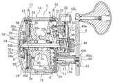
도 1은 본 발명의 일실시 형태에 의한 레버 드래그 릴의 단면도이다.1 is a cross-sectional view of a lever drag reel according to one embodiment of the present invention.
도 2는 그 측면도이다.2 is a side view thereof.
도 3은 스풀 록킹기구의 분해 사시도이다.3 is an exploded perspective view of the spool locking mechanism.
도 4a 및 도 4b는 스풀 록킹기구의 단면도이다.4A and 4B are cross-sectional views of the spool locking mechanism.
도 5는 역회전 방지기구의 정면도이다.5 is a front view of the reverse rotation prevention mechanism.
도 6은 역회전 방지기구의 분해 사시도이다.6 is an exploded perspective view of the reverse rotation prevention mechanism.
<부호의 간단한 설명><Short description of symbols>
1 릴 본체1 reel body
2 스풀축2 spool shaft
3 스풀3 spools
9 역회전 방지기구9 anti-rotation mechanism
36 마찰 디스크36 friction disc
50 래칫 휠50 ratchet wheel
50a 톱니50a tooth
51 래칫 후크 51 ratchet hook
52 매개부재52 media
54 접촉부재(위치 결정 수단)54 Contact member (positioning means)
54a 위치 결정부54a positioning unit
55 빠짐 방지부재55 fall prevention member
본 발명은, 역회전 방지기구, 특히, 양 베어링 릴의 릴 본체에 회전 가능하게 장착된 스풀의 낚시줄 방출 방향의 회전을 규제하기 위한 양 베어링 릴의 역회전 방지기구에 관한 것이다.The present invention relates to a reverse rotation prevention mechanism, in particular a reverse rotation prevention mechanism of both bearing reels for regulating the rotation of the fishing line discharge direction of the spool rotatably mounted to the reel unit of both bearing reels.
양 베어링 릴의 드래그 장치에는, 일반적으로, 드래그 작동시 스풀에 연동 가능한 연동부재의 낚시줄 방출 방향의 회전을 금지하기 위한 역회전 방지기구가 장착되어 있다. 예컨대, 핸들축의 주위에 설치된 스타 드래그형의 드래그 장치의 경우, 핸들축에 역회전 방지기구가 장착되어 있다. 또한 스풀축의 주위에 설치된 레버 드래그형의 드래그 장치인 경우, 스풀축 또는 드래그 디스크에 역회전 방지기구가 설치되어 있다.The drag device of both bearing reels is generally equipped with a reverse rotation prevention mechanism for prohibiting rotation of the fishing line discharge direction of the linkage member that is interlockable with the spool during the drag operation. For example, in the case of a star drag type drag device provided around the handle shaft, a reverse rotation prevention mechanism is attached to the handle shaft. In the case of a lever drag type drag device provided around the spool shaft, a reverse rotation prevention mechanism is provided on the spool shaft or the drag disk.
이러한 레버 드래그 릴의 제동 장치에 사용되는 역회전 방지기구에는, 일반적으로 후크식의 역회전 방지기구가 사용되고 있다. 후크식의 역회전 방지기구는, 외주부에 둘레 방향으로 간격을 두고 톱니부가 형성되고, 연동부재에 회전 불가능하게 장착된 회전부재와, 회전부재의 톱니부에 접촉되는 접촉자세와 이격되는 이격 자세 사이에서 요동 가능하게 릴 본체에 장착된 후크부재와, 후크부재를 접촉자세측으로 바이어스시키는 바이어스부재를 가지고 있다. 후크부재는, 선단이 요동 중심으로부터 낚시줄 권취 방향의 하류측에 배치되어 있다.In general, a hook type reverse rotation prevention mechanism is used as the reverse rotation prevention mechanism used in the brake device of the lever drag reel. The hook type reverse rotation prevention mechanism has a tooth portion formed at intervals in the circumferential direction at an outer circumferential portion thereof, and is disposed between a rotating member that is rotatably mounted to the interlocking member, and a spaced posture spaced apart from the contact posture contacting the tooth portion of the rotating member. It has a hook member mounted to the reel main body so as to be swingable, and a bias member for biasing the hook member toward the contact position. In the hook member, the tip is disposed on the downstream side in the fishing line winding direction from the swing center.
이와 같이 구성된 후크식의 역회전 방지기구에는, 스풀의 낚시줄 권취 방향의 회전에 연동하여 회전부재가 낚시줄 권취 방향으로 회전하면, 후크부재가 톱니부에 의해 이격자세측으로 압압된다. 그러나, 톱니부가 후크부재를 통과하면, 바이어스부재에 의해 접촉자세측으로 바이어스되어 회전부재에 접촉한다. 이 때문에, 낚시줄 권취 방향으로 스풀이 회전하면, 후크부재가 진동된 상태로 회전부재에 접촉하여 단속적인 클릭음이 발생한다. 이와 같은 클릭음이 발생하면, 예컨데 빈번하게 권취 동작을 반복하는 지깅 등의 낚시를 행하면, 소음이 연속적으로 발생하여 불쾌하게 된다. 더구나, 후크부재가 회전부재에 접촉되므로 권취시의 회전 저항도 증가하여 권취 효율도 저하된다.In the hook type reverse rotation prevention mechanism configured as described above, when the rotating member rotates in the fishing line winding direction in association with the rotation of the fishing line winding direction of the spool, the hook member is pressed by the toothed portion to the spaced apart side. However, when the tooth portion passes through the hook member, it is biased toward the contact posture side by the biasing member to contact the rotating member. For this reason, when the spool rotates in the fishing line winding direction, the hook member contacts the rotating member in a vibrated state, and an intermittent click sound is generated. When such a click sound is generated, for example, when fishing such as jigging which repeatedly winds up, the noise is continuously generated and becomes unpleasant. Moreover, since the hook member is in contact with the rotating member, the rotational resistance at the time of winding is also increased, and the winding efficiency is also lowered.
따라서, 낚시줄 권취시에 있어서의 클릭음을 없애기 위하여, 스프링에 의한 바이어스 대신에 마찰에 의해 후크부재를 바이어스시키는 바이어스부재를 구비한 것이 알려져 있다. 바이어스부재는, C자형으로 구부려진 박판부재로 구성되고, 후크부재에 삽입 고정되어 있다. 바이어스부재의 1쌍의 선단은, 회전부재의 양측면에 탄성적으로 접촉하여 회전부재를 끼움지지하고 있다. 이러한 마찰에 의한 바이어스부재를 구비한 역회전 방지기구에서는, 회전부재가 낚시줄 권취 방향으로 회전하면, 마찰에 의해 후크부재는 이격자세측으로 바이어스되고, 낚시줄 방출 방향으로 회전하면 마찰에 의해 접촉자세측으로 바이어스된다. 이 때문에, 낚시줄 권취시 클 릭음이 발생하지 않게 된다.Therefore, in order to eliminate the click sound at the time of winding up a fishing line, it is known that the bias member which biases a hook member by friction instead of the bias by a spring is known. The bias member is composed of a thin plate member bent in a C shape and is fixedly inserted into the hook member. The pair of tips of the biasing members elastically contact both sides of the rotating member to hold the rotating member. In the reverse rotation prevention mechanism provided with such a biasing member by friction, when the rotating member rotates in the fishing line winding direction, the hook member is biased toward the spaced apart side by friction, and when the rotating member rotates in the fishing line discharge direction, the contact posture is caused by friction. Biased to the side. For this reason, the click sound does not occur when the fishing line is wound up.
상기 종래의 역회전 방지기구에서는, 유지보수나 부품의 교환 등을 위하여 분해시 핸들축이나 스풀축 등의 연동부재를 뺄 때, 회전부재도 연동부재와 함께 움직이는 경우가 있다. 회전부재가 연동부재와 함께 이동하면, 회전부재를 끼움지지하고 있는 바이어스부재가 변형될 염려가 있다. 이를 방지하기 위해서는, 회전부재를 연동부재에 대하여 축 방향으로 상대 이동 가능하게 배치하여도 된다.In the above conventional anti-rotation mechanism, the rotating member may move together with the interlocking member when the interlocking member such as the handle shaft or the spool shaft is removed during disassembly for maintenance or parts replacement. When the rotating member moves together with the interlocking member, there is a fear that the biasing member holding the rotating member is deformed. In order to prevent this, the rotating member may be arranged to be relatively movable in the axial direction with respect to the interlocking member.
그러나, 이와 같이 회전부재를 이동 가능하게 배치하더라도 그리스 등의 윤활제의 영향이나 마찰 영향에 의해 회전부재가 연동부재의 이동에 의해 약간이라도 이동할 염려가 있다. 이러한 작은 이동으로도, 비교적 얇은 판재로 구성된 바이어스부재는 변형될 염려가 있다.However, even if the rotating member is arranged to be movable in this way, there is a fear that the rotating member may move slightly due to the movement of the interlocking member due to the influence of a lubricant such as grease or friction. Even with this small movement, the bias member composed of a relatively thin plate may be deformed.
바이어스부재가 변형되면, 바이어스부재와 회전부재 사이에 마찰력이 발생하지 않게 되고, 후크부재를 정상적으로 바이어스시킬 수 없게 된다. 그 결과, 역회전 방지기구가 정상적으로 동작하지 않게 된다.When the bias member is deformed, no friction force is generated between the bias member and the rotating member, and the hook member cannot be biased normally. As a result, the reverse rotation prevention mechanism does not operate normally.
본 발명의 과제는, 회전부재와의 마찰에 의해 후크부재를 바이어스시키는 바이어스부재를 구비한 역회전 방지기구에 있어서, 연동부재의 착탈시에 바이어스부재의 변형을 억제함에 있다.An object of the present invention is to suppress the deformation of a bias member when the interlocking member is attached or detached in the reverse rotation prevention mechanism including a bias member for biasing the hook member by friction with the rotating member.
발명 1에 따른 양 베어링 릴의 역회전 방지기구는, 양 베어링 릴의 릴 본체에 회전 가능하게 장착된 스풀의 낚시줄 방출 방향의 회전을 규제하기 위한 기구로 서, 회전부재와, 후크부재와, 빠짐 방지 수단과, 바이어스수단을 구비하고 있다. 회전부재는 외주부에 둘레 방향으로 간격을 두고 형성된 복수의 톱니부를 가지고, 스풀과 연동 가능한 연동부재에 축 방향 이동 가능하며 또한 회전 불가능하게 장착된 부재이다. 후크부재는 톱니부에 선단이 접촉되는 접촉자세와 톱니부로부터 이격되는 이격자세로 릴 본체에 요동 가능하게 장착되고, 접촉자세로 배치되면 회전부재의 낚시줄 방출 방향의 회전을 금지하는 부재이다. 빠짐 방지 수단은 릴 본체에 설치되고, 회전부재를 릴 본체에 대하여 빠짐 방지하는 수단이다. 바이어스수단은, 후크부재에 장착되며, 회전부재가 낚시줄 권취 방향으로 회전하였을 때 후크부재를 이격자세쪽으로 바이어스시키고, 낚시줄 방출 방향으로 회전하였을 때 접촉자세측으로 바이어스시키는 수단이다.The reverse rotation prevention mechanism of both bearing reels according to the first invention is a mechanism for regulating the rotation of the fishing line discharge direction of the spool rotatably mounted on the reel main body of both bearing reels, the rotating member, the hook member, A fallout prevention means and a biasing means are provided. The rotating member has a plurality of teeth formed at intervals in the circumferential direction at the outer circumferential portion, and is a member that is axially movable and is rotatably mounted to an interlocking member that is interlockable with the spool. The hook member is rotatably mounted to the reel unit with a contact posture where the tip is in contact with the tooth section and a spaced posture spaced apart from the tooth section, and the hook member is a member that prohibits rotation of the fishing line in the fishing line discharge direction when disposed in the contact posture. The fall prevention means is provided in the reel main body and is a means for preventing the rotating member from falling out with respect to the reel main body. The biasing means is attached to the hook member and is a means for biasing the hook member toward the spaced apart position when the rotating member rotates in the fishing line winding direction, and biasing the hook member toward the contact position when rotated in the fishing line discharge direction.
이 역회전 방지기구에서는, 핸들의 낚시줄 권취 방향의 회전에 의해 스풀이 낚시줄 권취 방향으로 회전하면, 회전부재도 낚시줄 권취 방향으로 회전한다. 그러면, 바이어스수단에 의해 후크부재가 이격자세측으로 바이어스되고, 후크부재는 회전부재에 충돌하지 않게 되어 클릭음이 발생하지 않는다. 또한 스풀이 낚시줄 방출 방향으로 회전하여 회전부재가 낚시줄 방출 방향으로 회전하려고 하면, 바이어스수단이 후크부재를 접촉 위치측으로 바이어스시키켜 회전부재의 낚시줄 방출 방향의 회전이 금지되어 드래그가 작동한다. 이러한 역회전 방지기구를 유지보수 등의 작업을 위해 분해할 때, 회전부재가 연동부재에 축 방향 이동 가능하게 장착됨과 동시에, 빠짐 방지 수단에 의해 릴 본체에 대하여 빠짐 방지되어 있다. 이 때문에, 연동부재의 착탈시 회전부재가 릴 본체측에 남고 축방향으로 이동하지 않는다. 따 라서, 연동부재의 착탈시 후크부재에 장착된 바이어스부재가 쉽게 변형되지 않는다.In this reverse rotation prevention mechanism, when the spool rotates in the fishing line winding direction by the rotation of the fishing line winding direction of the handle, the rotating member also rotates in the fishing line winding direction. Then, the hook member is biased toward the spaced apart side by the biasing means, and the hook member does not collide with the rotating member so that no click sound is generated. In addition, when the spool rotates in the fishing line discharge direction and the rotating member tries to rotate in the fishing line discharge direction, the biasing means biases the hook member toward the contact position, so that the rotation of the fishing line discharge direction of the rotating member is prohibited and the drag is operated. . When disassembling such a reverse rotation prevention mechanism for work | maintenance, etc., a rotating member is attached to an interlocking member so that an axial movement is possible, and it is prevented from falling with respect to a reel main body by a fall prevention means. For this reason, when the interlocking member is attached or detached, the rotating member remains on the reel main body side and does not move in the axial direction. Therefore, the bias member mounted on the hook member is not easily deformed when the interlocking member is attached or detached.
발명 2에 따른 양 베어링 릴의 역회전 방지기구는, 발명 1에 기재된 기구에 있어서, 바이어스수단은, 후크부재에 설치되고, 회전부재의 양측면을 탄성적으로 접촉하여 끼움지지하는 매개부재를 갖는다. 이 경우에는, 회전부재의 양측면에 탄성적으로 접촉하더라도, 매개부재가 연동부재의 착탈시 쉽게 변형되지 않는다. 또한, 회전부재의 양측면을 탄성적 접촉상태로 끼움지지하여 바이어스시키고 있으므로, 바이어스 동작의 확실성이 향상된다.The reverse rotation preventing mechanism of both bearing reels according to the second aspect of the invention is the mechanism according to the first aspect of the invention, wherein the biasing means is provided on the hook member, and has a medial member that elastically contacts both sides of the rotating member to be fitted. In this case, even when elastically contacting both sides of the rotating member, the intermediate member is not easily deformed when the interlocking member is attached or detached. In addition, since both sides of the rotating member are biased by being held in an elastic contact state, the reliability of the biasing operation is improved.
발명 3에 따른 양 베어링 릴의 역회전 방지기구는, 발명 1에 기재된 기구에 있어서, 빠짐 방지 수단은, 후크부재를 릴 본체에 대하여 빠짐 방지한다. 이 경우에는, 회전부재에 더하여 후크부재도 빠짐 방지되므로, 릴 본체로의 후크부재의 요동 지지 구조가 간소화된다.The reverse rotation prevention mechanism of both bearing reels which concerns on this
발명 4에 따른 양 베어링 릴의 역회전 방지기구는, 발명 1에 기재된 기구에 있어서, 회전부재의 회전 축심과 연동부재의 회전 축심이 정렬되도록 회전부재를 릴 본체에 대하여 위치 결정 가능한 위치 결정 수단을 더 구비한다. 이 경우에는, 회전부재를 릴 본체에 장착할 때 위치 결정되므로, 회전부재의 장착이 용이하게 된다.The reverse rotation prevention mechanism of both bearing reels according to the fourth aspect of the present invention provides a mechanism according to the first aspect of the present invention, wherein the rotation means of the rotating member and the rotation axis of the interlocking member are aligned so that the rotating member can be positioned relative to the reel unit. It is further provided. In this case, since the positioning is performed when the rotating member is mounted on the reel unit, the mounting of the rotating member becomes easy.
발명 5에 따른 양 베어링 릴의 역회전 방지기구는, 발명 1에 기재된 기구에 있어서, 빠짐 방지 수단은, 릴 본체에 고정되고 일단이 회전부재의 릴 본체와 반대쪽 측면에 대향하는 위치에 배치된 판상의 부재이다. 이 경우에는, 빠짐 방지 수단 이 판상의 부재로 구성되므로 빠짐 방지 수단의 구성이 간소하다.The reverse rotation preventing mechanism of both bearing reels according to the fifth aspect is the mechanism according to the first aspect of the present invention, wherein the release preventing means has a plate shape in which one end is fixed to the reel main body and one end thereof is disposed opposite to the side opposite to the reel main body of the rotating member. Is absent. In this case, since the removal prevention means is constituted by the plate-like member, the configuration of the removal prevention means is simple.
발명 6에 따른 양 베어링 릴의 역회전 방지기구는, 발명 1에 기재된 기구에 있어서, 연동부재는, 스풀을 회전 가능하게 지지하는 스풀축이다. 이 경우에는, 레버 드래그식의 드래그 기구에 사용되는 역회전 방지기구에 있어서, 바이어스부재의 변형을 방지할 수 있다.The reverse rotation prevention mechanism of both bearing reels which concerns on this invention 6 is a mechanism as described in
발명 7에 따른 양 베어링 릴의 역회전 방지기구는, 발명 1에 기재된 기구에 있어서, 연동부재는 스풀을 회전시키기 위한 핸들축이다. 이 경우에는 스타 드래그식의 드래그 기구에 사용되는 역회전 방지기구에 있어서, 바이어스부재의 변형을 방지할 수 있다.The reverse rotation prevention mechanism of both bearing reels which concerns on 7 is a mechanism as described in
〔전체 구성〕[Overall structure]
도 1에 있어서, 본 발명의 일실시 형태를 채용한 양 베어링 릴은 레버 드래그 릴이며, 통형상의 릴 본체(1)와, 릴 본체(1)의 중심부에 회전 가능하게 장착된 스풀축(2)과, 스풀축(2)에 회전 가능하며 또한 축 방향 이동 불가능하게 지지된 스풀(3)과,릴 본체(1)의 측방에 배치된 핸들(4)를 구비하고 있다. 또 레버 드래그 릴은,핸들(4)의 회전을 스풀(3)에 전달하는 회전 전달 기구(6)와, 스풀(3)의 낚시줄 방출 방향의 회전을 제동하는 레버 드래그 기구(7)와, 스풀(3)을 록킹시키는 스풀 록킹기구(8)와, 레버 드래그 기구(7)의 낚시줄 방출 방향의 회전을 규제하는 역회전 방지기구(9)를 릴 본체(1)의 내부에 구비하고 있다.In Fig. 1, both bearing reels employing one embodiment of the present invention are lever drag reels, and a cylindrical reel
〔릴 본체의 구성〕[Configuration of the reel body]
릴 본체(1)는, 금속제의 좌우 1쌍의 접시 모양의 측판(10, 11)과, 측판(10, 11)이 양단에 스피것(spigot)결합에 의해 동일중심을 가지도록 결합되어 복수개의 고정 볼트(13)에 의해 고정된 금속제의 구멍뚫린 통형상의 릴 몸체(12)를 가지고 있다. 측판(10, 11)과 릴 몸체(12) 사이에는, 릴을 몸체로 받치기 위하여 사용하는 1쌍의 하니스 러그(14)가 장착되어 있다. 측판(10, 11)은, 그 거의 중심부에서 회동 가능하게 스풀축(2)의 양단을 지지한다. 좌측의 측판(10)의 중심부 내측면에는 내측으로 돌출되는 통형 베어링 수납부(1Oa)가 형성되어 있다. 또한 좌측 측판(1O)의 스피것 결합 부분의 내주부(10d)는, 고정 볼트(13)를 피하는 상태에서 내주부를 언더컷 가공하여 살빼기 처리를 행하고 있다. 이에 따라, 릴 본체(1)의 경량화를 꾀하고 있다. 우측(핸들(4)측)의 측판(11)의 중심부에는, 스풀축(2)을 지지하기 위해 축 방향 외측으로 돌출되는 보스부(11a)가 형성되어 있고, 보스부(11a)의 주위에는, 핸들(4)의 핸들축(5)을 장착하기 위한 두꺼운 원판형의 베어링 블록(15)이 나사고정되어 있다. 릴 몸체(12)의 하부에는 릴을 낚싯대에 장착하기 위한 낚시대 장착부(19)가 설치되어 있다.The
스풀축(2)은, 양단에 배치된 좌우 1쌍의 베어링(31a, 31b)에 의해 릴 본체(1)의 측판(10, 11)에 회전 가능하게 지지되어 있다. 또한 그 내측에서 축 방향으로 간격을 두고 스풀(3)의 양단에 배치된 2개의 베어링(32a, 32b)에 의해 스풀(3)을 회전 가능하게 지지한다. 좌측의 베어링(31a)은, 좌측의 측판(10)에 형성된 베어링 수납부(10a)에 수납되어 있다. 우측의 베어링(31b)은, 우측의 측판(11)에 형성된 보스부(11a)에 장착되어 있다. 스풀축(2)의 우측 단부의 베어링(31b)의 외륜의 우측에는 레버 드래그 기구(7)의 드래그 이동 기구(38)(후 술)의 구성 부품이 접촉되어 있다. 또한 내륜의 좌측에는 회전 전달 기구(6)인 피니언기어(17)(후술)가 접촉되어 있다. 스풀축(2)의 좌측 단부의 베어링(31a)의 내륜의 우측에는 역회전 방지기구(9)가 접촉되어 있다. 또한 외륜의 좌측 단부에는, 측판(10)의 내측면이 접촉되어 있다. 스풀(3)을 지지하는 우측의 베어링(32b)의 외륜의 좌측에는 스풀(3)이 접촉되어 있다. 또한 내륜의 우측에는 와셔(미도시)를 통하여 4개의 접시스프링(34)이 접촉되어 있다. 이 접시 스프링(34)은, 제동 조작 레버(후술)의 요동에 대하여 드래그력을 급격하게 상승시키지 않고 광범위하게 드래그력을 조정 가능하게 하기 위하여 마련되어 있다. 스풀(3)을 지지하는 좌측의 베어링(32a)의 내륜의 좌측에는 레버 드래그 기구(7)의 후술하는 마찰 디스크(36)가 복귀 스프링(47)을 통하여 접촉되어 있다. 외륜의 우측은 스풀(3)에 접촉되어 있다.The
스풀(3)은, 낚시줄 권취 몸체부(3a)와 낚시줄 권취 몸체부(3a)의 양단에 일체로 형성된 플랜지부(3b)를 가지고 있다. 도 1의 우측(핸들 장착측)의 플랜지부(3b)의 외측에는, 스풀 록킹기구(8)가 마련되어 있다. 또한 도 1의 좌측의 플랜지부(3b)의 외측에는, 레버 드래그 기구(7)의 제동 디스크(35)가 장착되어 있다. 이 제동 디스크(35)를 커버하기 위한 커버부재(39)를 장착하기 위하여, 좌측의 플랜지부(3b)의 외주부는 스풀 축 방향의 외측으로 연장되는 통형부(3d)가 형성되어 있다.통형부(3d)의 내주면(3e)은, 언더컷 가공하여 살빼기 처리되어 있다. 이에 따라, 스풀(3)의 경량화를 꾀할 수 있어 스풀(3)의 관성이 감소된다.The
〔스풀 록킹기구의 구성〕 [Configuration of Spool Locking Mechanism]
스풀 록킹기구(8)는, 스풀(3)의 낚시줄 권취 방향의 회전을 허용하고, 낚시줄 방출 방향의 회전을 잠그는 기구이고, 도 2에 도시한 바와 같이, 릴 본체(1)의 뒷부분 근방에 배치되어 있다. 스풀 록킹기구(8)는, 도 3 및 도 4a, 도 4b에 도시한 바와 같이, 릴 본체(1)에 진출 위치(도 4a)와 후퇴 위치(도 4b)로 이동 가능하게 장착된 록킹부(21)와, 록킹부(21)를 진출 위치와 후퇴 위치로 이동시키는 록킹 이동 기구(22)와, 플랜지부(3b)의 외측면에 설치되고, 진출 위치로 진출한 록킹부(21)의 선단이 결합 가능한 록킹홈부(23)를 구비하고 있다.The
록킹부(21)는, 측판(11)에 고정된 수납부재(24)에 스풀축(2)과 평행한 축을 따라 이동 가능하게 장착된 이동부재(25)를 가지고 있다. 이동부재(25)는, 봉형상의 부재이고, 선단측으로부터 록킹돌기(25a), 플랜지부(25b), 축부(25c) 및 컷팅부(25d)를 가지고 있다. 록킹돌기(25a)는, 록킹홈부(23)에 결합되는 돌기이고, 도 4a 및 도 4b에 화살표로 나타낸 스풀(3)의 낚시줄 방출 방향의 상류측이 예각이고 하류쪽이 둔각으로 형성되어 있다. 이와 같이 형성된 록킹돌기(25a)는, 록킹홈부(23)에 결합될 때, 예각측에 록킹홈부(23)가 접촉하면 이동부재(25)가 다소 기울어져도 록킹홈부(23)에 확실하게 끼워져 들어가서 스풀(3)이 록킹되고, 둔각측에 록킹홈부(23)가 접촉하면, 록킹홈부(23)의 작용에 의해 이동부재(25)가 후퇴 가능하다. 플랜지부(25b)는, 록킹 이동 기구(22)를 구성하는 코일 스프링(26)을 걸어서 고정시키기 위한 것이다. 코일 스프링(26)은, 수납부재(24)의 내부에서 이동부재(25)의 축부(25c)의 외주측에 배치되어 있다. 코일 스프링(26)은, 이동부재(25)를 록킹홈부(23)측으로 바이어스시킨다. 축부(25c)는, 수납부재(24)에 축방 향으로 이동 가능하게 지지되어 있다. 또한 컷팅부(25d)에 의해 수납부재(24)에 회전 불가능하게 결합되어 있다. 즉, 수납부재(24)에는, 일단에 컷팅부(25d)에 결합될 수 있는 비원형의 구멍(24a)이 형성되어 있다. 이에 따라, 이동부재(25)는,릴 본체(1)에 축 방향으로 이동 가능하며, 또한 회전 불가능하게 장착된다. 이동부재(25)의 컷팅부(25d)의 후단부에는, 직경 방향을 따라 관통공(25e)이 형성되어 있다. 관통공(25e)에는, 록킹 이동 기구(22)를 구성하는 캠핀(30)이 장착되어 있다. 이 캠핀(30)에 의해 이동부재(25)의 진출 위치측의 위치 결정도 이루어져 있다. 상술한 바와 같은 형상의 록킹돌기(25a)와 코일 스프링(26)에 의한 압압에 의해, 진출 위치로 이동한 이동부재(25)가 록킹홈부(23)에 결합되면, 낚시줄 권취 방향의 회전이 허용되고 낚시줄 방출 방향의 회전이 록킹된다.The locking
록킹홈부(23)는, 록킹 플레이트(28)에 회전 방향을 따라 간격을 두고 형성된 절제부에 의해 구성되어 있다. 록킹 플레이트(28)는, 스풀(3)의 도 1 우측의 플랜지부(3b)의 외측면에 고정된 링형상의 플레이트이다. 스풀(3)의 플랜지부(3b)의 록킹홈부(23)가 형성된 외측면에는, 록킹홈부(23)에 대향된 위치와 환상(環狀)으로 패인 리세스(3c)가 형성되어 있다. 이와 같은 리세스(3c)를 형성함으로써 이동부재(25)의 록킹돌기(25a)가 록킹홈부(23)를 관통할 수 있다.The locking
록킹 이동 기구(22)는, 측판(11)에 이동부재(25)의 축 둘레로 요동 가능하게 장착된 록킹 레버(27)와, 상술한 코일 스프링(26)과, 록킹 레버(27)의 요동에 따라 이동부재(25)를 코일 스프링(26)의 바이어스력에 대항하여 진출 위치로부터 후퇴 위치로 이동시키는 록킹 캠 기구(29)를 가지고 있다. 록킹 레버(27)는, 도 2에 도 시한 바와 같이, 진출 위치에 따른 2점 쇄선으로 표시한 진출자세와 후퇴 위치에 따른 실선으로 표시한 후퇴자세로 토글 스프링(37)에 의해 바이어스된다. 록킹 캠 기구(29)는, 록킹 레버(27)의 기단부(基端部) 내측 벽면에 나선형으로 형성된 경사 캠면(27a)과, 이동부재(25)의 후단부에 경사 캠면(27a)에 결합되도록 장착된 캠핀(30)을 가지고 있다.The
핸들(4)은, 도 1 및 도 2에 도시한 바와 같이, 스풀축(2)의 하방에 스풀축(2)과 평행하게 배치된 통형상의 핸들축(5)의 돌출단에 고정 볼트(60)에 의해 고정되어 있다. 고정 볼트(60)에는, 플랜지부(60a)가 형성되어 있다. 플랜지부(60a)에는, 외주면에 오목부(60b)가 둘레 방향으로 간격을 두고 형성되어 있고, 오목부(60b)에 머리부분이 결합되는 나사(61)에 의해 회전 방지되어 있다. 핸들축(5)은, 보스부(11a)의 앞쪽 하방에서 베어링 블록(15)에 끼워진 통형 부재(15a)에 회전 가능하게 장착되어 있다. 핸들축(5)의 선단에는, 메인기어(16)가 회전 불가능하게 장착되어 있다.As shown in Figs. 1 and 2, the
회전 전달 기구(6)는, 도 1에 도시한 바와 같이, 핸들(4)의 핸들축(5)에 회전 가능하게 지지된 메인기어(16) 및 스풀축(2)에 일체로 형성된 피니언기어(17)를 가지고 있다. 핸들(4)의 회전은, 핸들축(5), 메인기어(16), 피니언기어(17)를 통하여 스풀축(2)에 전달된다.As shown in FIG. 1, the rotation transmission mechanism 6 includes a pinion gear integrally formed with the
레버 드래그 기구(7)는, 도 1에 도시한 바와 같이, 스풀(3)의 도 1 좌측의 플랜지부(3b)의 외측면에 장착된 제동 디스크(35)와, 제동 디스크(35)에 접촉 가능하게 배치된 마찰 디스크(36)와, 스풀(3) 및 마찰 디스크(36)를 스풀 축 방향으로 왕복 이동시키기 위한 드래그 이동 기구(38)를 가지고 있다.As shown in FIG. 1, the lever drag mechanism 7 contacts the
제동 디스크(35)는, 예컨대 스테인레스제의 와셔 형상의 원판부재이고, 직경 방향 안쪽의 측면에 둘레 방향으로 간격을 두고 배치된 복수개의 장착 나사(40)에 의해, 스풀(3)의 좌측의 플랜지부(3b)의 외측면에 스풀(3)에 대하여 회전 불가능하게 장착되어 있다. 제동 디스크(35)의 장착 나사(40)의 장착부(35a)는, 직경 방향의 외측보다 오목하게 환상으로 패여 있다. 이에 따라, 드래그 면적, 특히 직경 방향 외측의 드래그 면적이 쉽게 제한되지 않게 되어, 스풀(3)의 외경에 대응하는 최대 직경의 제동 디스크(35)를 사용 가능하게 된다.The
마찰 디스크(36)는, 제동 디스크(35)와 대향하여 배치되어 있다. 마찰 디스크(36)의 제동 디스크(35)에 대향하는 면에는, 예컨대 카본 그라파이트나 섬유 강화 수지 등의 내마모 소재로 된 링형상의 마찰판(36a)이 나사 등의 적절한 고정 수단에 의해 고정되어 있다. 마찰 디스크(36)는, 중심부에 축 방향 외측으로 돌출되는 통형상의 보스부(36b)를 가지고 있고, 이 보스부(36b)에 스풀축(2)의 직경 방향을 따라 관통하여 스풀축(2)에 장착된 핀(2a)이 결합되어 있다. 이에 따라 마찰 디스크(36)는, 스풀축(2)에 회전 불가능하게 장착되어 있고, 스풀축(2)과 함께 회전한다. 또한 마찰 디스크(36)의 보스부(36b)의 도 1 좌단면에는 역회전 방지기구(9)의 래칫 휠(50)이 회전 불가능하며 또한 축 방향으로 이동 가능하게 장착되어 있다. 또한 마찰 디스크(36)는, 커버부재(39)에 의해 덮혀 있다. 마찰 디스크(36)의 보스부(36b)는, 커버부재(39)를 관통하여 베어링(31a)측으로 연장되어 있다. 커버부재(39)의 관통 부분과 보스부(36b) 사이에는 실링부재(39a)가 설치되어 있다.
The
〔역회전 방지기구의 구성〕[Configuration of reverse rotation prevention mechanism]
역회전 방지기구(9)는, 도 5 및 도 6에 도시한 바와 같이, 외주면에 톱니(50a)가 형성된 래칫 휠(회전부재의 일예)(50)과, 래칫 휠(50)의 외주측에 배치되어 선단이 톱니(50a)에 걸리는 1쌍의 래칫 후크(후크부재의 일예)(51)를 가지는 래칫형 일방향 클러치이다.As shown in Figs. 5 and 6, the reverse
래칫 휠(50)은, 마찰 디스크(36)의 보스부(36b)의 외주면에, 예컨대 세레이션 등의 적절한 결합수단에 의해 회전 불가능하게 그리고 축 방향 외측(도 1의 좌측)으로 이동 가능하게 장착되어 있다. 이 결과 래칫 휠(50)은, 스풀축(연동부재의 일예)(2)에 마찰 디스크(36)를 통하여 회전 불가능하게 그리고 축 방향으로 이동 가능하게 장착되어 있다. 래칫 휠(50)은, 도 1의 좌측면에 동축으로 장착된 링형상의 접촉부재(54)를 가지고 있다. 접촉부재(54)는, 베어링(31a)의 내륜의 우측 단면에 접촉함과 동시에, 베어링 수납부(1Oa)의 내주면에 근접 배치되는 위치 결정부(54a)를 외주면에 가지고 있다. 이러한 접촉부재(54)를 설치하면, 래칫 휠(50)을 측판(10)에 대해 동축적으로 장착 가능해지므로, 래칫 휠(50)의 조립이 용이하다. 또한, 베어링(31a)의 외륜은 상술한 바와 같이 측판(10)에 접촉되어 있다.The
래칫 휠(50)은, 1쌍의 빠짐 방지부재(55)에 의해 측판(10)에 대하여 빠짐 방지되어 있다. 빠짐 방지부재(55)는, 측판(10)에 고정된, 예컨데 스테인레스 합금제 등의 금속제의 판상 부재이고, 일단부(55a)가 측판(10)에 고정되어 있다. 빠짐 방지부재(55)에는, 일단부(55a)로부터 크랭크형상으로 마찰 디스크(36)측으로 절곡되 어 래칫 후크(51)를 건너는 중앙부(55b)가 형성되고, 다시 측판(10)측으로 크랭크형상으로 절곡되어 고정부(55c)가 형성되어 있다. 이 고정부(55c)에도 측판(10)에 고정되어 있다. 고정부(55c)로부터 다시 래칫 휠(50)측으로 만곡되어 크랭크형상으로 절곡되어 타단부(55d)가 형성되어 있다. 타단부(55d)는, 래칫 휠(50)의 마찰 디스크(36)측의 측면에 대향하는 위치에 배치되어 있다. 이 타단부(55d)에 의해 래칫 휠(50)이 빠짐 방지된다. 또한 중앙부(55b)에서 래칫 후크(51)의 축 방향의 이동이 규제되어 빠짐 방지된다.The
1쌍의 래칫 후크(51)는, 스풀 축심에 대하여 점대칭의 위치에 배치되어 있고, 측판(10)의 내측면에 톱니(50a)와 접촉하는 접촉자세와 톱니(50a)로부터 이격되는 이격자세로 요동 가능하게 장착되어 있다. 래칫 후크(51)의 선단은, 요동 축심보다 래칫 휠(50)의 낚시줄 권취 방향(R)의 하류측에 배치되어 있다. 측판(10)에는, 래칫 후크(51)를 요동 가능하게 장착하기 위한 1쌍의 후크 보스(10b)가 베어링 수납부(1Oa)를 사이에 두고 대칭인 위치에 형성되어 있다. 또한 1쌍의 후크 보스(10b)를 사이에 두고 2개의 장착 보스(10c)가 형성되어 있다. 후크 보스(10b)에는,래칫 후크(51)를 요동 가능하게 측판(10)에 장착하기 위한 요동핀(53)이 장착되어 있다. 요동핀(53)도, 빠짐 방지부재(55)에 의해 축 방향의 이동이 규제되어 빠짐 방지되어 있다. 2개의 장착 보스(10c)는, 빠짐 방지부재(55)를 일단부(55a)와 고정부(55c)에서 측판(10)에 나사고정하기 위해 마련되어 있다.The pair of ratchet hooks 51 are arranged in a point symmetrical position with respect to the spool shaft center and are spaced apart from the contact posture in contact with the
래칫 후크(51)의 중간부에는, C자형으로 절곡된 매개부재(바이어스수단의 일예)(52)가 삽입 고정되어 있다. 매개부재(52)의 1쌍의 선단(52a)은, 래칫 휠(50)의 양측면에 탄성적으로 접촉하여 래칫 휠(50)을 끼움지지하고 있다. 이 매개부재(52)는, 래칫 휠(50)이 낚시줄 권취 방향(R)으로 회전하면, 래칫 휠(50)과의 마찰에 의해 래칫 후크(51)를 이격자세측으로 바이어스시킨다. 바이어스된 래칫 후크(51)는, 빠짐 방지부재(55)에 접촉하여 이격자세로 유지된다. 또한 래칫 휠(50)이 반대로 낚시줄 방출 방향으로 회전하면, 래칫 휠(50)과의 마찰에 의해 래칫 후크(51)를 접촉자세측으로 바이어스시킨다. 이에 따라, 낚시줄 권취시에 래칫 후크(51)가 래칫 휠(50)의 톱니(50a)에 접촉하지 않게 되어 소음을 억제할 수 있다. 또한, 회전 저항의 증가를 억제하여 스풀(3)의 권취 효율의 저하를 억제할 수도 있다.In the middle portion of the
그 결과, 마찰 디스크(36)는, 스풀 축 방향의 외측(도 1 좌측), 즉 제동 디스크(36)로부터 이격되는 방향으로 이동 불가능함과 동시에, 역회전 방지기구(9)에 의해 낚시줄 권취 방향의 회전이 허가되고 낚시줄 방출 방향의 회전이 금지된다.As a result, the
여기서, 제동 해제 상태에 있을 때, 도 1의 스풀 축심의 하측에 도시한 바와 같이 마찰 디스크(36)의 마찰판(36a)과 제동 디스크(35) 사이에 간극이 생기고, 제동 상태에 있을 때는, 도 1의 스풀 축심의 상측에 도시한 바와 같이 양자가 밀착된다. 이 밀착 정도를 조정함으로써 드래그력이 변화된다.Here, when in the brake release state, a gap is generated between the
드래그 이동 기구(38)는, 도 1에 도시한 바와 같이, 릴 본체(1)에 요동 가능하게 설치된 제동 조작 레버(45)와, 제동 조작 레버(45)의 도 2의 시계 방향의 요동에 따라 스풀(3) 및 제동 디스크(35)를 압압하여 도 1의 좌측으로 이동시키는 압압 기구(46)와, 마찰 디스크(36)와 스풀(3) 사이에 배치되고, 제동 조작 레버(45)의 도 2 반시계 방향의 이동에 따라 스풀을 도 1 우측으로 이동시키기 위한 복귀 스프링(47)을 가지고 있다.As shown in FIG. 1, the
복귀 스프링(47)은, 마찰 디스크(36)와 베어링(32a) 사이에 있어서 스풀축(2)의 외주측에 압축 상태로 장착되어 마찰 디스크(36)를 제동 디스크(35)(스풀(3))로부터 이격되는 방향으로 바이어스시키며, 제동 디스크(35)(스풀(3))를 도 1의 우측으로 바이어스시킨다.The
제동 조작 레버(45)는, 도 2에 실선으로 표시한 제동 해제 위치와 2점 쇄선으로 표시한 최대 제동 위치 사이에서 릴 본체(1)에 요동 가능하게 장착되어 있다. 제동 조작 레버(45)는, 보스부(11a)에 요동 가능하게 장착되는 레버부(45a)와, 레버부(45a)의 선단에 고정된 손잡이부(45b)를 가지고 있다. 레버부(45a)의 기단부는, 압압 기구(46)에 회전 불가능하게 결합되어 있다.The
이어서 레버 드래그 기구(7)의 제동 동작에 대하여 설명하기로 한다.Next, the braking operation of the lever drag mechanism 7 will be described.
레버 드래그 기구(7)에서는, 제동 조작 레버(45)를 도 2에 2점 쇄선으로 표시한 제동 위치로부터 실선으로 표시한 제동 해제 위치로 요동시키면, 도 1의 스풀축심의 상측에 표시한 상태로부터 하측에 표시한 상태로 변화된다. 우선, 복귀 스프링(47)의 바이어스력에 의해 스풀(3)이 압압되어 도 1 우측으로 이동한다. 이에 따라, 제동 디스크(35)와 마찰 디스크(36) 사이에 간극이 발생한다. 또한 베어링(32a)을 통하여 스풀(3)이 압압되어 우측으로 이동한다. 이에 따라 스풀(3)의 제동이 해제된다. 한편, 스풀(3)이 이동하면, 베어링(32b), 접시 스프링(34), 피니언기어(17) 및 베어링(31b)을 통하여 압압 기구가 압압되어 도 1 우측으로 후퇴한다.그리고, 제동 조작 레버(45)가 제동 해제 위치로 요동하면 도 1의 스풀 축 심의 하측의 상태로 이동한다.In the lever drag mechanism 7, when the
한편, 제동 조작 레버(45)를 도 2에 실선으로 표시한 제동 해제 위치로부터 2점 쇄선으로 표시한 제동 위치로 요동시키면, 도 1의 스풀 축심의 하측에 도시한 상태로부터 상측에 도시한 상태로 변화한다. 우선, 제동 조작 레버(45)의 요동에 의해 압압 기구(46)가 스풀 축 방향 좌측으로 이동한다. 이에 따라 베어링(31b)의 외륜이 압압되어 이동하고, 피니언기어(17), 접시 스프링(34) 및 베어링(32b)을 통하여 스풀(3)이 압압되어 스풀 축 방향 좌측(도 1 좌측)으로 이동한다. 그 결과,제동 디스크(35)도 축 방향 좌측으로 이동한다. 그 결과, 제동 디스크(35)가 마찰 디스크(36)에 접근한다. 그리고, 제동 디스크(35)가, 축방향으로 이동 불가능하고 또한 낚시줄 방출 방향으로 회전 불가능한 마찰 디스크(36)에 접촉하면, 드래그력이 스풀(3)에 작용한다. 그리고, 제동 조작 레버(45)를 최대 요동 위치까지 요동시키면, 압압력이 최대가 되고, 제동 디스크(35)가 마찰 디스크(36)에 의해 압압되어 큰 드래그력을 얻을 수 있다.On the other hand, when the
이 상태에서 핸들(4)의 회전에 의해 스풀(3)이 낚시줄 권취 방향으로 회전하면, 마찰 디스크(36)를 통하여 래칫 휠(50)도 낚시줄 권취 방향(R)(도 5)으로 회전한다. 그러면, 매개부재(52)는, 래칫 휠(50)과의 마찰에 의해, 낚시줄 권취 방향(R)으로 끌려간다. 그 결과, 래칫 후크(51)는 매개부재(52)에 의해 이격자세측으로 바이어스되어 이격자세로 요동하여 빠짐 방지부재(55)에 접촉된다. 이 때문에, 스풀(3)이 낚시줄 권취 방향으로 회전할 때는, 래칫 휠(50)과 래칫 후크(51)와의 충돌에 의한 클릭음은 발생하지 않는다.
When the
한편, 낚시바늘 뭉치에 물고기가 걸려 스풀(3)이 낚시줄 방출 방향으로 회전하면, 래칫 휠(50)도 낚시줄 방출 방향으로 회전한다. 그러면, 매개부재(52)는, 래칫 휠(50)과의 마찰에 의해, 낚시줄 권취 방향(R)과 반대의 낚시줄 방출 방향으로 끌려간다. 그 결과, 래칫 후크(51)는 매개부재(52)에 의해 접촉자세측으로 바이어스되어 접촉자세로 요동한다. 이 때문에, 스풀(3)이 낚시줄 방출 방향으로 회전할 때는, 래칫 휠(50)의 낚시줄 방출 방향의 회전이 금지된다. 그 결과, 마찰 디스크(36)의 낚시줄 방출 방향의 회전이 저지되어 스풀(3)에 설정된 드래그력이 작용한다.On the other hand, when a fish is caught in the fishing needle bundle and the
이어서, 레버 드래그 릴의 조작 방법에 대하여 설명하기로 한다.Next, a method of operating the lever drag reel will be described.
스풀로 낚시줄을 권취할 때는, 핸들(4)을 낚시줄 권취 방향으로 회전시킨다.그러면, 핸들(4)의 회전이 핸들축(5), 메인기어(16), 피니언기어(17), 스풀축(2), 레버 드래그 기구(7)를 통하여 스풀(3)에 전달되어 스풀(3)이 회전한다.When winding the fishing line with the spool, the
한편, 낚시바늘뭉치가 수초 등에 걸렸을 때 스풀(3)을 록킹시키는 경우에는, 록킹 레버(27)를 도 2의 실선으로 표시한 위치로부터 2점 쇄선으로 표시한 위치로 요동시킨다. 그러면, 코일 스프링(26)에 의해 바이어스된 이동부재(25)가 진출 위치측으로 진출하고, 록킹돌기(25a)가 록킹홈부(23)에 걸려서, 스풀(3)의 낚시줄 방출 방향으로의 회전이 록킹된다. 이 상태에서 낚시줄을 권취하여 낚시줄을 팽팽하게 한 후, 낚싯대를 낚시바늘뭉치를 향해 똑바로 잡아 당긴다. 이렇게 함으로써, 걸린 상대 물건, 낚시 바늘, 낚시줄, 혹은 그 결속부가 파손되어 낚시바늘뭉치 또는 낚시바늘뭉치의 일부를 회수할 수 있다.
On the other hand, when locking the
이 때, 이동부재(25)는, 플랜지부(25b)와 축부(25c)가 수납부재(24)에 접촉하여 힘을 받는다. 이 록킹시에는, 스풀(3)에 마련된 록킹홈부(23)에 이동부재(25)를 결합함으로써 스풀(3)을 록킹시키고 있으므로, 스풀(3)을 직접 록킹할 수 있고, 무리한 힘이 작용하더라도 스풀 록킹기구(8)가 쉽게 파손이나 변형되지 않는다. 또한 록킹홈부(23)가 플랜지부(3b)의 외측면에 설치되어 있으므로, 낚시줄을 방출한 상태에서는 통상 낚시줄의 권취직경과 같거나 큰 직경 부분에 록킹홈부(23)가 배치된다. 이 때문에, 이동부재(25)에 작용하는 힘이 낚시줄의 장력과 동등하거나 작아진다. 따라서, 스풀 록킹기구(8)가 더욱 파손이나 변형되기 어려워진다.At this time, the
또한 록킹돌기(25a)는 상술한 바와 같이 낚시줄 방출 방향 하류측이 둔각으로 되어 있고, 또한 이동부재(25)가 코일 스프링(26)에 의해 바이어스되고 있으므로, 스풀(3)이 낚시줄 권취 방향으로 회전하면, 이동부재(25)가 록킹홈부(23)에 의해 압압되어 후퇴 위치측으로 이동한다. 따라서, 스풀 록킹 중에 실수로 스풀(3)을 낚시줄 권취 방향으로 회전시키더라도 회전 전달 기구(6) 등에 무리한 힘이 작용하지 않는다.As described above, the locking
한편, 릴의 유지보수 등을 위해 스풀(3)과 함께 스풀축(2)를 빼면, 래칫 휠(50)이 그리스의 점성이나 마찰에 의해 스풀축(2)과 함께 축 방향으로 이동하는 경우가 있다. 그러나, 여기에서는, 빠짐 방지부재(55)에 의해 래칫 휠(50)은 빠짐 방지되어 있다. 이 때문에, 래칫 휠(50)은 스풀(3)과 함께 스풀축(2)를 빼어도 보스부(36b)로부터 벗어나 측판(10)측에 남게 되어 있다. 따라서, 스풀축(2)을 착탈할 때, 래칫 후크(51)에 장착된 매개부재(52)가 변형되거나 손상되는 일이 없다.
On the other hand, when the
〔다른 실시 형태〕[Other Embodiments]
(a) 상기 실시 형태에서는, 스풀 축이 연동부재인 레버 드래그식의 드래그 기구에 이용되는 역회전 방지기구를 예로서 설명하였지만, 핸들 축이 연동부재인 스타드래그식의 드래그 기구에 이용되는 역회전 방지기구에도 본 발명을 적용할 수 있다.(a) Although the reverse rotation prevention mechanism used for the lever drag type drag mechanism whose spool shaft is an interlocking member was demonstrated as an example in the said embodiment, the reverse rotation used for the star drag type drag mechanism whose handle shaft is an interlocking member is described. The present invention can also be applied to a prevention mechanism.
(b) 상기 실시 형태에서는, 래칫 휠(50)의 양 측면에 접촉하여 끼움지지하는 매개부재에 의해 바이어스수단을 구성하였지만, 바이어스수단은 스풀측의 일면에만 접촉하는 것으로 하여도 된다.(b) In the above embodiment, the biasing means is constituted by the intermediate member which is in contact with both sides of the
(c) 상기 실시 형태에서는, 마찰 디스크(36)를 통하여 래칫 휠(50)을 스풀축(2)에 회전 불가능하고 또한 축 방향 이동 가능하게 장착하였지만 스풀축(2)에 직접 장착해도 된다.(c) In the above embodiment, the
본 발명에 의하면, 회전부재가 연동부재에 축 방향 이동 가능하게 장착됨과 동시에, 빠짐 방지 수단에 의해 릴 본체에 대하여 빠짐 방지되어 있다. 이 때문에, 연동부재의 착탈시, 회전부재가 릴 본체측에 남고 축 방향으로 이동하지 않는다. 따라서, 연동부재의 착탈시 후크부재에 장착된 바이어스부재가 쉽게 변형되지 않는다.According to the present invention, the rotating member is attached to the interlocking member so as to be movable in the axial direction, and is prevented from falling off from the reel unit by the release preventing means. For this reason, when the interlocking member is attached or detached, the rotating member remains on the reel main body side and does not move in the axial direction. Therefore, the bias member mounted on the hook member is not easily deformed when the interlocking member is attached or detached.
Claims (7)
Applications Claiming Priority (2)
| Application Number | Priority Date | Filing Date | Title |
|---|---|---|---|
| JP2000261523A JP4381580B2 (en) | 2000-08-30 | 2000-08-30 | Double bearing reel reverse rotation prevention mechanism |
| JPJP-P-2000-00261523 | 2000-08-30 |
Publications (2)
| Publication Number | Publication Date |
|---|---|
| KR20020017946A KR20020017946A (en) | 2002-03-07 |
| KR100722538B1 true KR100722538B1 (en) | 2007-05-28 |
Family
ID=18749351
Family Applications (1)
| Application Number | Title | Priority Date | Filing Date |
|---|---|---|---|
| KR1020010040247A Expired - Fee Related KR100722538B1 (en) | 2000-08-30 | 2001-07-06 | Reverse rotation preventing device of double bearing reel |
Country Status (9)
| Country | Link |
|---|---|
| US (1) | US6517021B2 (en) |
| EP (1) | EP1183946B1 (en) |
| JP (1) | JP4381580B2 (en) |
| KR (1) | KR100722538B1 (en) |
| CN (1) | CN1225165C (en) |
| AT (1) | ATE279103T1 (en) |
| AU (1) | AU779135B2 (en) |
| DE (1) | DE60106355T2 (en) |
| TW (1) | TW504368B (en) |
Families Citing this family (14)
| Publication number | Priority date | Publication date | Assignee | Title |
|---|---|---|---|---|
| JP4381733B2 (en) * | 2003-06-26 | 2009-12-09 | 株式会社シマノ | Double bearing reel |
| US6634586B1 (en) * | 2002-07-02 | 2003-10-21 | Liang-Jen Chang | Anti-reversional mechanism for trolling reel |
| US7198219B1 (en) * | 2005-05-27 | 2007-04-03 | Harout Alajajyan | Fishing reel transmission |
| US7128287B1 (en) * | 2005-11-10 | 2006-10-31 | Okuma Fishing Tackle Co. Ltd. | Fishing reel |
| GB2461876B (en) * | 2008-07-14 | 2011-03-09 | Lead Innovations | Retracting dog lead with manual override |
| KR101126546B1 (en) * | 2009-06-26 | 2012-03-26 | 주식회사 도요엔지니어링 | bait reel for fishing |
| JP5961378B2 (en) * | 2011-12-22 | 2016-08-02 | 株式会社シマノ | Drag adjusting device for double-bearing reel |
| JP6200287B2 (en) * | 2013-11-14 | 2017-09-20 | シマノコンポネンツ マレーシア エスディーエヌ.ビーエッチディー. | Double bearing reel |
| JP6467218B2 (en) * | 2014-12-19 | 2019-02-06 | 株式会社シマノ | Double bearing reel |
| JP6518514B2 (en) * | 2015-05-28 | 2019-05-22 | 株式会社シマノ | Double bearing reel |
| JP6886344B2 (en) * | 2017-05-17 | 2021-06-16 | 株式会社シマノ | Double bearing reel |
| JP7086827B2 (en) * | 2018-12-14 | 2022-06-20 | 株式会社シマノ | Fishing reel cap |
| CN113049487B (en) * | 2021-03-22 | 2022-03-18 | 北京航空航天大学 | A test system and method for calculating the friction coefficient of inclined roller friction discs |
| US12484564B2 (en) | 2022-01-27 | 2025-12-02 | TrikaUSA Inc. | Anti-reverse mechanism for fishing reel |
Family Cites Families (7)
| Publication number | Priority date | Publication date | Assignee | Title |
|---|---|---|---|---|
| US3989204A (en) * | 1968-01-05 | 1976-11-02 | Carpano & Pons S.A. | Fly fishing reel |
| GB2206022B (en) * | 1987-05-23 | 1991-04-17 | Shimano Industrial Co | Double-bearing fishing reel |
| US5201870A (en) * | 1990-12-14 | 1993-04-13 | Newell Carl W | Reverse stop rachet and pawl for a fishing reel |
| US5415359A (en) * | 1991-02-05 | 1995-05-16 | Ikuta; Takeshi | Fishing reel |
| JP2957882B2 (en) * | 1994-02-22 | 1999-10-06 | ダイワ精工株式会社 | Fishing reel |
| US6056223A (en) * | 1996-08-21 | 2000-05-02 | Kirby; Thomas Glen | Drag mounted spring for spin-cast reels |
| AUPO185596A0 (en) * | 1996-08-23 | 1996-09-19 | Jarvis Walker Pty Ltd | A spinning reel for fishing |
-
2000
- 2000-08-30 JP JP2000261523A patent/JP4381580B2/en not_active Expired - Fee Related
-
2001
- 2001-06-15 TW TW090114624A patent/TW504368B/en not_active IP Right Cessation
- 2001-07-06 KR KR1020010040247A patent/KR100722538B1/en not_active Expired - Fee Related
- 2001-08-21 DE DE60106355T patent/DE60106355T2/en not_active Expired - Lifetime
- 2001-08-21 EP EP01307096A patent/EP1183946B1/en not_active Expired - Lifetime
- 2001-08-21 AT AT01307096T patent/ATE279103T1/en not_active IP Right Cessation
- 2001-08-22 AU AU63593/01A patent/AU779135B2/en not_active Ceased
- 2001-08-23 US US09/934,517 patent/US6517021B2/en not_active Expired - Lifetime
- 2001-08-30 CN CNB011258934A patent/CN1225165C/en not_active Expired - Fee Related
Also Published As
| Publication number | Publication date |
|---|---|
| TW504368B (en) | 2002-10-01 |
| JP4381580B2 (en) | 2009-12-09 |
| EP1183946A1 (en) | 2002-03-06 |
| US20020023978A1 (en) | 2002-02-28 |
| KR20020017946A (en) | 2002-03-07 |
| DE60106355T2 (en) | 2006-02-02 |
| EP1183946B1 (en) | 2004-10-13 |
| CN1341354A (en) | 2002-03-27 |
| AU6359301A (en) | 2002-03-07 |
| JP2002065129A (en) | 2002-03-05 |
| CN1225165C (en) | 2005-11-02 |
| AU779135B2 (en) | 2005-01-06 |
| ATE279103T1 (en) | 2004-10-15 |
| US6517021B2 (en) | 2003-02-11 |
| DE60106355D1 (en) | 2004-11-18 |
Similar Documents
| Publication | Publication Date | Title |
|---|---|---|
| KR100722538B1 (en) | Reverse rotation preventing device of double bearing reel | |
| JP5153269B2 (en) | Roller clutch | |
| KR101815621B1 (en) | Dual-bearing reel drag sound producing device | |
| KR101694222B1 (en) | Dual bearing reel speed-change operation mechanism | |
| KR20020015643A (en) | Spool locking device of double bearing reel | |
| CN100456930C (en) | Spinning reel sounding mechanism | |
| JP2009063052A5 (en) | ||
| KR20110087213A (en) | Drag sound generating device of dual bearing reel | |
| KR20110019714A (en) | Spinning Reel Spool Connection Structure | |
| KR20110006600A (en) | Dual bearing reel sound generator | |
| JP2011019428A (en) | Dual-bearing reel lever drag mechanism | |
| JP4451773B2 (en) | One-way clutch of double-bearing reel | |
| KR101185510B1 (en) | Drag control member attachment structure | |
| KR20150056031A (en) | Dual-bearing reel | |
| EP2189059B1 (en) | Drag Adjusting Device for Dual -Bearing Reel | |
| JP2006180777A5 (en) | ||
| TWI858243B (en) | Spinning Reel | |
| JP4834240B2 (en) | Double-bearing reel drag adjustment mechanism | |
| JP4381885B2 (en) | Braking operation structure of fishing reel spool | |
| JP6489885B2 (en) | Spinning reel | |
| JP4834786B2 (en) | Double-bearing reel drag adjustment mechanism | |
| TW202418991A (en) | Spool sounding mechanism and dual-bearing reel for fishing | |
| JP2016174543A5 (en) | ||
| JP2009063051A (en) | Roller clutch | |
| JP2004135513A (en) | Backstop of lever drag reel |
Legal Events
| Date | Code | Title | Description |
|---|---|---|---|
| PA0109 | Patent application |
St.27 status event code: A-0-1-A10-A12-nap-PA0109 |
|
| PG1501 | Laying open of application |
St.27 status event code: A-1-1-Q10-Q12-nap-PG1501 |
|
| R17-X000 | Change to representative recorded |
St.27 status event code: A-3-3-R10-R17-oth-X000 |
|
| R17-X000 | Change to representative recorded |
St.27 status event code: A-3-3-R10-R17-oth-X000 |
|
| A201 | Request for examination | ||
| PA0201 | Request for examination |
St.27 status event code: A-1-2-D10-D11-exm-PA0201 |
|
| R18-X000 | Changes to party contact information recorded |
St.27 status event code: A-3-3-R10-R18-oth-X000 |
|
| E701 | Decision to grant or registration of patent right | ||
| PE0701 | Decision of registration |
St.27 status event code: A-1-2-D10-D22-exm-PE0701 |
|
| GRNT | Written decision to grant | ||
| PR0701 | Registration of establishment |
St.27 status event code: A-2-4-F10-F11-exm-PR0701 |
|
| PR1002 | Payment of registration fee |
St.27 status event code: A-2-2-U10-U11-oth-PR1002 Fee payment year number: 1 |
|
| PG1601 | Publication of registration |
St.27 status event code: A-4-4-Q10-Q13-nap-PG1601 |
|
| PR1001 | Payment of annual fee |
St.27 status event code: A-4-4-U10-U11-oth-PR1001 Fee payment year number: 4 |
|
| PR1001 | Payment of annual fee |
St.27 status event code: A-4-4-U10-U11-oth-PR1001 Fee payment year number: 5 |
|
| PR1001 | Payment of annual fee |
St.27 status event code: A-4-4-U10-U11-oth-PR1001 Fee payment year number: 6 |
|
| FPAY | Annual fee payment |
Payment date: 20130503 Year of fee payment: 7 |
|
| PR1001 | Payment of annual fee |
St.27 status event code: A-4-4-U10-U11-oth-PR1001 Fee payment year number: 7 |
|
| FPAY | Annual fee payment |
Payment date: 20140502 Year of fee payment: 8 |
|
| PR1001 | Payment of annual fee |
St.27 status event code: A-4-4-U10-U11-oth-PR1001 Fee payment year number: 8 |
|
| FPAY | Annual fee payment |
Payment date: 20150416 Year of fee payment: 9 |
|
| PR1001 | Payment of annual fee |
St.27 status event code: A-4-4-U10-U11-oth-PR1001 Fee payment year number: 9 |
|
| FPAY | Annual fee payment |
Payment date: 20160418 Year of fee payment: 10 |
|
| PR1001 | Payment of annual fee |
St.27 status event code: A-4-4-U10-U11-oth-PR1001 Fee payment year number: 10 |
|
| FPAY | Annual fee payment |
Payment date: 20170421 Year of fee payment: 11 |
|
| PR1001 | Payment of annual fee |
St.27 status event code: A-4-4-U10-U11-oth-PR1001 Fee payment year number: 11 |
|
| FPAY | Annual fee payment |
Payment date: 20180502 Year of fee payment: 12 |
|
| PR1001 | Payment of annual fee |
St.27 status event code: A-4-4-U10-U11-oth-PR1001 Fee payment year number: 12 |
|
| FPAY | Annual fee payment |
Payment date: 20190429 Year of fee payment: 13 |
|
| PR1001 | Payment of annual fee |
St.27 status event code: A-4-4-U10-U11-oth-PR1001 Fee payment year number: 13 |
|
| PR1001 | Payment of annual fee |
St.27 status event code: A-4-4-U10-U11-oth-PR1001 Fee payment year number: 14 |
|
| PC1903 | Unpaid annual fee |
St.27 status event code: A-4-4-U10-U13-oth-PC1903 Not in force date: 20210522 Payment event data comment text: Termination Category : DEFAULT_OF_REGISTRATION_FEE |
|
| PC1903 | Unpaid annual fee |
St.27 status event code: N-4-6-H10-H13-oth-PC1903 Ip right cessation event data comment text: Termination Category : DEFAULT_OF_REGISTRATION_FEE Not in force date: 20210522 |