KR100690691B1 - Volume error compensation system of machine tool - Google Patents
Volume error compensation system of machine tool Download PDFInfo
- Publication number
- KR100690691B1 KR100690691B1 KR1020030064470A KR20030064470A KR100690691B1 KR 100690691 B1 KR100690691 B1 KR 100690691B1 KR 1020030064470 A KR1020030064470 A KR 1020030064470A KR 20030064470 A KR20030064470 A KR 20030064470A KR 100690691 B1 KR100690691 B1 KR 100690691B1
- Authority
- KR
- South Korea
- Prior art keywords
- machine tool
- measurement
- error
- data
- machine
- Prior art date
- Legal status (The legal status is an assumption and is not a legal conclusion. Google has not performed a legal analysis and makes no representation as to the accuracy of the status listed.)
- Expired - Fee Related
Links
Images


Classifications
-
- G—PHYSICS
- G05—CONTROLLING; REGULATING
- G05B—CONTROL OR REGULATING SYSTEMS IN GENERAL; FUNCTIONAL ELEMENTS OF SUCH SYSTEMS; MONITORING OR TESTING ARRANGEMENTS FOR SUCH SYSTEMS OR ELEMENTS
- G05B19/00—Program-control systems
- G05B19/02—Program-control systems electric
- G05B19/18—Numerical control [NC], i.e. automatically operating machines, in particular machine tools, e.g. in a manufacturing environment, so as to execute positioning, movement or co-ordinated operations by means of program data in numerical form
- G05B19/404—Numerical control [NC], i.e. automatically operating machines, in particular machine tools, e.g. in a manufacturing environment, so as to execute positioning, movement or co-ordinated operations by means of program data in numerical form characterised by control arrangements for compensation, e.g. for backlash, overshoot, tool offset, tool wear, temperature, machine construction errors, load, inertia
-
- B—PERFORMING OPERATIONS; TRANSPORTING
- B23—MACHINE TOOLS; METAL-WORKING NOT OTHERWISE PROVIDED FOR
- B23Q—DETAILS, COMPONENTS, OR ACCESSORIES FOR MACHINE TOOLS, e.g. ARRANGEMENTS FOR COPYING OR CONTROLLING; MACHINE TOOLS IN GENERAL CHARACTERISED BY THE CONSTRUCTION OF PARTICULAR DETAILS OR COMPONENTS; COMBINATIONS OR ASSOCIATIONS OF METAL-WORKING MACHINES, NOT DIRECTED TO A PARTICULAR RESULT
- B23Q11/00—Accessories fitted to machine tools for keeping tools or parts of the machine in good working condition or for cooling work; Safety devices specially combined with or arranged in, or specially adapted for use in connection with, machine tools
- B23Q11/0003—Arrangements for preventing undesired thermal effects on tools or parts of the machine
- B23Q11/0007—Arrangements for preventing undesired thermal effects on tools or parts of the machine by compensating occurring thermal dilations
-
- G—PHYSICS
- G05—CONTROLLING; REGULATING
- G05B—CONTROL OR REGULATING SYSTEMS IN GENERAL; FUNCTIONAL ELEMENTS OF SUCH SYSTEMS; MONITORING OR TESTING ARRANGEMENTS FOR SUCH SYSTEMS OR ELEMENTS
- G05B19/00—Program-control systems
- G05B19/02—Program-control systems electric
- G05B19/18—Numerical control [NC], i.e. automatically operating machines, in particular machine tools, e.g. in a manufacturing environment, so as to execute positioning, movement or co-ordinated operations by means of program data in numerical form
- G05B19/414—Structure of the control system, e.g. common controller or multiprocessor systems, interface to servo, programmable interface controller
- G05B19/4145—Structure of the control system, e.g. common controller or multiprocessor systems, interface to servo, programmable interface controller characterised by using same processor to execute programmable controller and numerical controller function [CNC] and PC controlled NC [PCNC]
-
- G—PHYSICS
- G05—CONTROLLING; REGULATING
- G05B—CONTROL OR REGULATING SYSTEMS IN GENERAL; FUNCTIONAL ELEMENTS OF SUCH SYSTEMS; MONITORING OR TESTING ARRANGEMENTS FOR SUCH SYSTEMS OR ELEMENTS
- G05B2219/00—Program-control systems
- G05B2219/30—Nc systems
- G05B2219/33—Director till display
- G05B2219/33098—Several nc machines, dnc, cnc
-
- G—PHYSICS
- G05—CONTROLLING; REGULATING
- G05B—CONTROL OR REGULATING SYSTEMS IN GENERAL; FUNCTIONAL ELEMENTS OF SUCH SYSTEMS; MONITORING OR TESTING ARRANGEMENTS FOR SUCH SYSTEMS OR ELEMENTS
- G05B2219/00—Program-control systems
- G05B2219/30—Nc systems
- G05B2219/33—Director till display
- G05B2219/33099—Computer numerical control [CNC]; Software control [SWC]
Landscapes
- Engineering & Computer Science (AREA)
- Human Computer Interaction (AREA)
- Manufacturing & Machinery (AREA)
- Physics & Mathematics (AREA)
- General Physics & Mathematics (AREA)
- Automation & Control Theory (AREA)
- Mechanical Engineering (AREA)
- Numerical Control (AREA)
Abstract
본 발명은 공작기계의 체적오차보상시스템에 관한 것으로서;The present invention relates to a volume error compensation system of a machine tool;
금형가공용 등의 공작기계에 의한 열체적변화에 따른 오차를 보상하기 위한 공작기계의 체적오차보상시스템에 있어서, 상기 시스템은 기상측정(On Machine Measurement)을 수행하며, 다축 평행이동식의 탄성기구를 가지는 스캐닝프로브를 장착한 상기 공작기계의 구동에 따른 데이터를 전송하는 통신수단과. 상기 통신수단으로 전송받은 점군데이터에 기반하여 형상을 해석하는 데이터해석용의 프로그램을 내장하는 게인용컴퓨터 등의 해석수단을 구비하고, 상기 시스템은 해석수단에 의하여 해석된 수정가공데이터를 상기 공작기계에 재전송하여 오차를 보정하게 하는 것을 특징으로 한다.In a volume error compensation system of a machine tool for compensating for errors caused by a change in thermal volume by a machine tool such as a mold processing, the system performs on-machine measurement and has an elastic mechanism of a multi-axis parallel movement type. Communication means for transmitting data according to the drive of the machine tool equipped with a scanning probe. Analysis means, such as a gain computer for embedding a program for data analysis for analyzing the shape based on the point group data received by the communication means, the system includes the modified processing data analyzed by the analysis means for the machine tool It is characterized by retransmitting to correct the error.
공작기계, 체적, 오차, 보상Machine Tool, Volume, Error, Compensation
Description
도 1 은 기상측정을 설명하기 위한 모식적인 설명도.BRIEF DESCRIPTION OF THE DRAWINGS Explanatory drawing for demonstrating meteorological measurement.
도 2 는 열변형 보상을 위한 보정방법을 설명하는 흐름도.2 is a flowchart for explaining a correction method for thermal deformation compensation.
도 3 은 온도에 대한 열변형 오차를 산출하는 방법의 예시적인 도표.3 is an exemplary diagram of a method of calculating a heat deflection error with respect to temperature.
도 4 는 공작기계이 주축의 운동방향을 도시하는 설명도.4 is an explanatory diagram showing the direction of movement of the main shaft of the machine tool;
도 5 는 공작기계에서의 5 개의 센서를 사용하여 각각의 열변형 오차를 평가하는 구성도.5 is a configuration diagram for evaluating each thermal deformation error using five sensors in the machine tool.
도 6 은 본 발명의 실시예에 사용된 수직형 머시닝센터(AV45, 대우종합기계(주))의 재원표.Figure 6 is a financial table of the vertical machining center (AV45, Daewoo Machinery Co., Ltd.) used in the embodiment of the present invention.
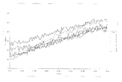
도 7 은 열전대를 도 6 의 공작기계의 주축 주요부에 7곳을 선택하여 장착하여 측정한 측정그래프도.Fig. 7 is a measurement graph showing the thermocouples selected and attached to seven main parts of the main shaft of the machine tool of Fig. 6;
도 8 은 대기온의 상승에 따른 공작기계의 주축변위의 영향을 도시하는 그래프도.8 is a graph showing the influence of the spindle displacement of the machine tool with the rise of the atmospheric temperature.
도 9 는 주축회전수의 변화를 도시하는 그래프도.9 is a graph showing changes in spindle speed.
도 10 은 공자기계의 주축회전수를 1,000, 2,000, 3,000, 4,000rpm으로 증가시킨 후 다시 반복적으로 회전수를 계속하여 증가시키면서 측정한 온도 데이터의 그랴프도.FIG. 10 is a glyph diagram of temperature data measured while increasing the spindle speed of a confusing machine to 1,000, 2,000, 3,000, and 4,000 rpm and then repeatedly increasing the revolution speed.
도 11 은 도 10 에 해당하는 주축의 열변형량의 그래프도.FIG. 11 is a graph of thermal deformation of the main shaft corresponding to FIG. 10. FIG.
도 12 는 공작기계의 채널 1과 3번의 y축 방향의 데이터의 그래프도.12 is a graph of data in the y-axis direction of
도 13 은 최고 주축 회전수의 75%로서 연속운전을 하는 경우 , 회전수 3,000rpm 에서의 온도상승 그래프도.Fig. 13 is a graph of temperature rise at a rotational speed of 3,000 rpm when the continuous operation is performed at 75% of the highest spindle speed.
도 14 는 주축의 열변형 그래프도.14 is a thermal deformation graph of the main axis;
도 15 는 랜덤하게 온도를 변화시키는 상태에서의 속도변화에 대한 온도의 그래프도.15 is a graph of temperature with respect to speed change in a state of randomly changing temperature.
도 16 은 주축 변위를 도시하는 그래프도.16 is a graph showing major axis displacement.
도 17 은 본 발명에서 제안되는 CAD 모델의 재설계 및 가공오류에 대한 재수정이 가능한 시스템의 전체 구성도.17 is an overall configuration diagram of a system capable of redesigning the CAD model proposed in the present invention and re-correction for machining errors.
도 18 은 본 발명에 채용되는 SP2-1 스캐닝 프로브(scanning probe)의 외관을 도시하는 정면도.Fig. 18 is a front view showing the appearance of the SP2-1 scanning probe employed in the present invention.
도 19 는 도 18 의 SP2-1 스캐닝 프로브의 사용방법을 도시하는 사진.19 is a photograph showing a method of using the SP2-1 scanning probe of FIG. 18.
도 20 은 본 발명의 기상측정수단의 시스템구성도.20 is a system configuration diagram of the meteorological measuring means of the present invention.
도 21 은 본 발명 규명에 사용된 측정용 소프트웨어인 상업용 CAM 시스템인 Z-Master 2000 의 캡쳐화면.FIG. 21 is a screenshot of Z-Master 2000, a commercial CAM system that is measurement software used in the present invention.
도 22, 23 은 도 21 의 소프트웨어의 사용을 도시하는 캡쳐도.22, 23 are capture diagrams illustrating the use of the software of FIG.
도 24 는 측정단계에서 입력점에 대한 측정 및 검사를 수행하여 측정결과를 실시간으로 보여주고 파일로 저장함을 설명하는 도 21 의 소프트웨어의 사용을 도 시하는 캡쳐도.FIG. 24 is a capture diagram illustrating the use of the software of FIG. 21 illustrating measurement and inspection of the input points in the measurement step to show the measurement results in real time and to save them to a file.
도 25 는 본 발명의 해석에 기초하는 Z-map 의 자료구조의 원리를 설명하는 설명도.25 is an explanatory diagram for explaining the principle of a data structure of Z-map based on the analysis of the present invention;
도 26 은 도 25 의 원리에 기초하여 대량의 점군 데이터를 얻기 위한 실가공물(a)의 그림.FIG. 26 is a diagram of a workpiece (a) for obtaining a large amount of point group data based on the principle of FIG. 25; FIG.
도 27 은 도 26 에 기초하여 각각의 측정 영역으로 나누고 그 영역에 대한 연속 측정 경로를 생성한((b))상태를 도시하는 설명도.FIG. 27 is an explanatory diagram showing a state (b) of dividing each measurement area based on FIG. 26 and generating a continuous measurement path for the area; FIG.
도 28 은 본 발명의 구성원리가 적용된 예시적인 실가공기를 도시하는 사진 및 가공상태를 도시하는 사진.Fig. 28 is a photograph showing an exemplary yarn processing machine to which a member of the present invention is applied;
본 발명은 공작기계의 체적오차보상시스템에 관한 것으로서, 더욱 상세히는 금형제조 등의 공작기계 가공에서의 가공불량을 저감하고 가공정도를 증대할 수 있는 시스템의 제공에 관한 것이다. The present invention relates to a volume error compensation system of a machine tool, and more particularly, to a system for reducing machining defects and increasing machining accuracy in machine tool processing such as mold manufacturing.
금형 제조업 분야에서 금형 가공 후 측정/검사 및 역공학 (reverse engineering)에 대한 실제적인 요구가 증대되고 있는 실정이다. In the mold manufacturing industry, there is an increasing demand for measurement / inspection and reverse engineering after mold processing.
현재 금형 제작 공수의 많은 부분은 NC 가공이 차지하며, 일반적으로 가공 불량은 NC 데이터 제작 오류 및 가공 오류에서 기인한다. Currently, a large part of the mold manufacturing work is accounted for by NC machining, and machining defects are generally caused by NC data manufacturing errors and machining errors.
이와 같은 오류는 실 가공 전 소프트웨어적인 모의가공, 가공 후 제반 수치 측정으로 확인이 가능하며, 본 발명은 일차적으로 스캐닝프루브를 이용하여 가공 직후 NC 기계 상에서 금형 곡면의 수치 측정 및 검사를 통하여 가공 오류를 파악할 수 있는 시스템을 개발하였다. 일반 고가의 CMM 장비를 필요로 하지 아니하므로, 측정 및 검사 시간을 대폭 단축할 수 있다. 또한 본 발명은 기존 기상 측정 시스템의 단점인 공작기계 체적오차를 측정, 보상함으로써 정밀도를 향상시키는 발명을 수행하였다. Such errors can be confirmed by software simulation before actual machining and various numerical measurements after machining, and the present invention primarily deals with machining errors through numerical measurement and inspection of the mold surface on an NC machine immediately after machining using a scanning probe. We have developed a grasping system. It eliminates the need for general expensive CMM equipment, greatly reducing measurement and inspection time. In addition, the present invention performed the invention to improve the precision by measuring and compensating for the volume error of the machine tool, which is a disadvantage of the conventional weather measurement system.
이하의 부수된 도면과 함께 본 발명의 공작기계의 체적오차보상시스템의 구성과 작동을 더욱 더 상세하게 설명한다.The construction and operation of the volume error compensation system of the machine tool of the present invention together with the accompanying drawings will be described in more detail.
본 발명에서는 본 발명 기술이 적용되는 기본적인 원리와 본 발명이 구현하고자 하는 기술적인 구성을 서술적으로 이론을 기본으로 순차 설명한다.In the present invention, the basic principle to which the present technology is applied and the technical configuration to be implemented by the present invention will be described sequentially based on the theory.
기상측정(機上測定: On Machine Measurement)은 가공이 완료된 가공물에 대해서 가공물을 기계에서 분리하지 않은 상태에서 가공을 마친 공작기계에 측정용 센서를 부착하여 측정 및 평가를 하는 것을 말한다. On machine measurement refers to the measurement and evaluation of the finished workpiece by attaching a measuring sensor to the finished machine tool without removing the workpiece from the machine.
즉, 도 1 에서 보는 바와 같이 가공을 완료후 측정을 할 때 가공을 한 가공기를 직접 측정기로 사용하는 기술이다.In other words, as shown in Figure 1 is a technology that uses a processing machine as a direct measuring device when measuring after the completion of processing.
기상측정기술은 가공물을 공작기계에서 분리하지 않고 측정을 할 수 있기 때문에 무엇보다도 측정의 생산성을 높일 수 있다는 점에서 많은 관심의 대상이 되고 있다. The meteorological measurement technology has been of great interest in that it is possible to increase the productivity of the measurement because the measurement can be performed without separating the workpiece from the machine tool.
그러나 가공계와 측정계가 동일함에 의해서 측정의 신뢰성을 확보할 수 없다는 것이 최대의 단점이 된다.However, the biggest disadvantage is that the reliability of the measurement cannot be secured due to the same processing system and measurement system.
즉, 공작기계가 가지고 있는 정적 또는 준정적인 오차와 함께 운동으로 인하여 발생하는 동적인 오차를 포함한 상태에서 측정을 하게 된다. In other words, the measurement is performed in the state including the dynamic error generated by the movement together with the static or quasi-static error of the machine tool.
그러나 측정 시에는 정적인 상태에서 측정이 이루어지기 때문에 공작기계에는 기하학적인 오차와 발열에 의한 변형이 주로 포함되게 된다. 이중 공작기계의 기하학적인 오차는 구조물의 부정확한 제작, 부정확한 조립, 이송 유니트의 부정확성, 서보 시스템 등으로부터 발생된다. However, since the measurement is performed in a static state during measurement, the machine tool mainly includes geometrical errors and deformation due to heat generation. Geometric errors in double machine tools arise from incorrect fabrication of structures, incorrect assembly, inaccuracies in transfer units, servo systems, etc.
한편 공작기계는 가공중에 주축과 이송계의 계속적인 운동으로 인하여 발열이 일으나며, 이로 인하여 구조물 또는 주축의 변형이 발생하고 또한 이송계의 원점을 변화시키게 된다. 이러한 열변형을 일으키는 원인은 주축 베어링, 이송체와 안내부, 이송나사, 이송나사용 베어링부의 마찰과 함께, 절삭영역에서의 절삭열, 그리고 각종 모터류가 중요한 발열부가 되기 때문이다. On the other hand, the machine tool generates heat due to the continuous movement of the spindle and the feed system during processing, which causes deformation of the structure or the spindle and also changes the origin of the feed system. The cause of such thermal deformation is due to the friction of the spindle bearing, the conveying body and the guide part, the feed screw, the feed screw bearing part, the cutting heat in the cutting area, and various motors, which become important heat generating parts.
이러한 발열에 의하여 가장 많은 영향을 받는 부위가 주축부이며, 상대적으로 구조물의 열변형은 이에 비하여 작은 편이다. 또한, 발열은 이송계의 기하학적 오차성분을 변화시키게 되며, 이로 인하여 이송계의 오차는 매우 복잡한 양상을 띄게 된다. 이 중에서 특히 주축계의 열변형은 전체 공작기계의 열변형의 70% 이상을 차지하기 때문에 대단히 중요한 오차의 요인으로 손꼽히고 있다.The most affected area by this heat generation is the main shaft part, and the thermal deformation of the structure is relatively small. In addition, the heat generation changes the geometric error component of the feed system, and thus the error of the feed system is very complicated. In particular, the thermal deformation of the main shaft system accounts for more than 70% of the thermal deformation of the entire machine tool is considered as a very important error factor.
이상과 같이 공작기계에 존재하는 기하학적인 오차와 열적인 변형을 고려하여 기상계측을 한다면 상당한 부분까지 기계의 정밀도를 향상시킬 수가 있고 이에 따라서 기상계측의 평가 신뢰도를 높일 수가 있다. As described above, if meteorological measurement is performed in consideration of geometrical errors and thermal deformations present in the machine tool, the precision of the machine can be improved to a considerable extent, thereby increasing the evaluation reliability of the meteorological measurement.
이를 보상하기 위한 방법을 정리하면 도 2 와 같다. 즉, 열변형을 예측하기 위하여 특정부위의 발열을 측정하여야 한다. A method for compensating for this is as shown in FIG. 2. In other words, the heat generation of a specific part should be measured to predict thermal deformation.
이를 위하여 발열량을 이론적으로 구할 수도 있고, 경우에 따라서는 특정부위의 온도를 측정하는 방법을 사용할 수도 있다. 이론적으로 발열량을 구한다는 것은 각종 계수의 부정확성, 발열 모델과 경계조건 등의 모호성 등에 의해서 부정확할 수 밖에 없다. For this purpose, the calorific value may be theoretically calculated, and in some cases, a method of measuring the temperature of a specific portion may be used. Theoretically, calculating calorific value is inaccurate due to inaccuracies of various coefficients, ambiguity of the calorific model and boundary conditions, and the like.
따라서 대부분의 경우에는 특정 영역에 열전대를 심어놓고 그 부위의 온도를 측정하는 방법을 사용하고 있으나, 이 또한 상업성을 고려한다면 설계상의 제약, 발열위치와 오프셋됨에 의해 정확한 발열량의 평가가 불가능함과 동시에 열이 전달될 때까지 걸리는 시간지연요소에 의한 모델의 부정확성 등의 문제를 드러내고는 있으나 많은 경우 이 방법을 채택하고 있다.Therefore, in most cases, a thermocouple is planted in a specific area and the temperature is measured.However, considering commerciality, it is impossible to evaluate the calorific value due to design constraints and offset from the heating location. Although it reveals problems such as model inaccuracy due to the time delay factor before heat is transferred, in many cases this method is adopted.
한편 계산된 발열량이나 또는 측정된 온도 정보를 이용하여 열변형량을 예측할 수가 있다. On the other hand, the heat distortion amount can be predicted using the calculated calorific value or measured temperature information.
열변형의 예측은 해석적인 방법과 실험적인 방법에 의해 이루어질 수가 있다. 해석적인 방법은 유한요소법 또는 유한차분법 등을 적용하게 되지만, 기계의 경계조건이나 입력조건 등에 대한 부정확한 정보에 의해 많은 오차를 수반하게 된다.Prediction of thermal deformation can be made by analytical and experimental methods. The analytical method applies the finite element method or the finite difference method, but it is accompanied by a lot of errors due to inaccurate information about the boundary condition or input condition of the machine.
실험적인 방법으로는 대부분 온도데이터와 열변형 데이터를 상호간에 매핑을 함에 의해 임의의 온도에 대한 변형을 예측하게 된다. In the experimental method, most of the temperature data and heat deformation data are mapped to each other to predict deformation for an arbitrary temperature.
현재 도3 의 도표에서와 같은 여러 가지 방법이 시행되어지고 있으나 각각의 장단점이 명확하기 때문에 결정에 있어서는 주의를 요한다.At present, various methods have been implemented as in the diagram of FIG. 3, but each of the advantages and disadvantages is clear, so care must be taken in the determination.
한편, 열변형량이 예측이 되어지면 이 데이터를 이용하여 보정을 하게 된다. 보정을 하는 방법은 여러 가지가 있으나 기계 서보루프의 위치 피이드백 신호에 아나로그 전압을 삽입하는 아날로그 보상이나 디지털 I/O 포트를 이용한 기계의 구동신호 수정을 통한 원점 이동보상법 등을 이용하여 기계를 보정하여 오차를 줄인다.On the other hand, when the thermal deformation is predicted, the data is corrected using this data. There are many ways to calibrate, but use the analog compensation that inserts analog voltage into the position feedback signal of the machine servo loop or the home movement compensation method by modifying the driving signal of the machine using the digital I / O port. Calibrate to reduce error.
그러나 본 발명에서는 실시간 보정보다는 측정한 결과에 대해서 보상을 하는 방식을 사용해야 하기 때문에 측정시 기록된 온도 데이터를 바탕으로 열변형량을 예측하고 예측된 열변형량을 측정된 결과에 보상하는 방법을 채택한다.However, in the present invention, since a method of compensating for the measured result should be used rather than real-time correction, a method of predicting the thermal strain based on the temperature data recorded during the measurement and compensating the predicted thermal strain to the measured result is adopted.
열변형 다음으로 측정정밀도에 영향을 미치는 것은 공작기계 이송계의 기하학적인 정밀도이다. Next to thermal deformation, it is the geometric precision of the machine tool feed system that affects the measurement accuracy.
이 정밀도는 위치의 함수로 나타나기 때문에 각축의 위치에 대해서 체적오차를 구한 후 이를 보상하는 방법이 가장 현실적이다. 이를 위한 방법은 각 축에서 나타나는 오차성분을 동차좌표변환을 통하여 공구 끝단으로 매핑시킴에 의해 공구의 끝단 또는 측정기의 끝단에서 발생할 오차를 계산적으로 구하는 방법이다. Since this precision is expressed as a function of position, it is most realistic to find the volume error for the position of each axis and then compensate for it. The method is to calculate the error that occurs at the end of the tool or the end of the measuring instrument by mapping the error components appearing in each axis to the tool tip through homogeneous coordinate transformation.
이런 방법으로 체적오차가 구해지면 주축의 열변형과 같이 직접적으로 측정데이터를 보상하는 방법을 사용하면 된다. If the volume error is found in this way, the measurement data can be compensated directly, such as thermal deformation of the main shaft.
한편 이때 문제가 되는 것은 이송계의 열적인 영향이다. 사실 기하학적 오차를 보상하기 위하여 측정하는 3축 공작기계에서의 21개 오차 성분은 기계가 가동되지 않은 정적인 상태에서 측정이 이루어진 것이고, 가공 중에는 이들 오차 성분들 도 온도에 따라서 변화하기 때문에 이에 대한 고찰이 필요하다. The problem at this time is the thermal effect of the feed system. In fact, the 21 error components of the 3-axis machine tool measured to compensate for the geometric error were measured in the static state without the machine running, and these errors are also changed with temperature during machining. This is necessary.
따라서 본 발명에서는 이들의 영향을 별도로 평가하여 봄으로써 온도에 대해 변화하는 이들 성분의 영향을 동시에 평가하여 대안을 제시하고자 한다.Therefore, in the present invention, by evaluating the effects of these separately, it is intended to simultaneously evaluate the effects of these components that change on temperature and propose alternatives.
이상의 내용을 정리하자면, 기상측정 방법에서 측정한 데이터는 공작기계 본연의 오차를 내포하고 있기 때문에 이 오차를 측정된 측정결과에 보상을 하여 줌으로써 측정의 정밀도를 향상시키고자 하는 것이다. In summary, since the data measured by the meteorological measurement method includes the inherent error of the machine tool, the accuracy of the measurement is improved by compensating the error to the measured measurement result.
이를 위하여 주축의 열변형과 공작기계의 기하학적 오차를 주요 오차요인으로 잡고, 이를 보상하는 총괄적인 방안에 대한 발명을 하게 되었다.To this end, we have invented a comprehensive plan that compensates for this, taking the main deformation as the main error factor and the thermal deformation of the main shaft.
(1) 주축의 열변형 평가(1) Evaluation of heat deformation of the main shaft
[실험예]Experimental Example
전술하였듯이 주축의 열변형은 공작기계의 정밀도에 가장 많은 영향을 미친다. 이러한 오차를 1 차적으로 측정된 결과에 대해서 보상을 한다면 상당한 측정 정밀도를 향상시킬 수가 있을 것이다. As mentioned above, the thermal deformation of the spindle has the most influence on the precision of the machine tool. Compensating for these errors in the primary measurement results will significantly improve measurement accuracy.
주축의 운동은 일반적으로 6가지가 있다. 즉, x, y, z방향에 대한 3개의 선형운동과 2개의 x, y방향에 대한 틸팅운동, 그리고 회전축에 대한 틸팅운동이 도. 4처럼 존재한다. There are generally six main shaft movements. That is, three linear motions in the x, y, and z directions, two tilting motions in the x, y directions, and a tilting motion about the rotation axis are shown in FIG. Exists like 4
이 중에서 회전축에 대한 틸팅운동은 자신의 운동방향과 일치하기 때문에 제외한다. Of these, the tilting motion about the axis of rotation is excluded because it coincides with its own direction of motion.
따라서 공작기계의 주축이 회전으로 인하여 발열이 일어나면 이 운동방향으로 오차가 각각 발생하게 된다. 따라서 이러한 운동을 측정하기 위해서는 Therefore, if heat is generated due to the rotation of the main shaft of the machine tool, an error occurs in this direction of movement, respectively. So to measure these movements
도 5 처럼 5 개의 센서를 사용하여 각각의 열변형 오차를 평가해낼 수가 있는데, 이는 ISO/DIS 230-3 및 BS3800:part3:1990, 그리고 ASME B5.54-1992에 잘 나타나 있다.Five sensors can be used to evaluate each thermal strain error, as shown in Figure 5, which is shown in ISO / DIS 230-3 and BS3800: part3: 1990, and ASME B5.54-1992.
도 5 에서 2번과 4번 센서는 각각 x방향의 선형오차 및 y방향의 틸팅오차를 평가하기 위한 것이고, 1번과 3번은 y방향의 선형오차 및 x방향의 틸팅오차, 그리고 센서 5는 z는 z방향의 선형오차를 측정하기 위한 센서이다. In FIG. 5, the 2nd and 4th sensors are for evaluating the linear error in the x direction and the tilting error in the y direction, respectively, and the 1st and 3rd sensors are the linear error in the y direction and the tilting error in the x direction, and the
센서는 와전류 형식의 비접촉식 센서를 사용하였다. 이 센서는 열에 의한 변형이 작도록 특별히 제작된 치구에 조립이 되며, 테스트바로 사용된 맨드렐도 열변형이 작은 강으로 제작되었으며, 두 센서와의 거리는 250mm가 되도록 게이지 기준면에서 길이가 300mm인 기준바를 사용하였다. The sensor used a non-contact type sensor of eddy current type. The sensor is assembled to a specially designed jig for small thermal deformation, and the mandrel used as a test bar is also made of steel with low thermal deformation.The distance between the two sensors is 250mm. Bar was used.
열변형은 일반적으로 금형가공에 많이 사용하는 크기의 도 6 의 도표와 같은 수직형 머시닝센터(AV45, 대우종합기계(주))를 이용하였다. Heat deformation was performed using a vertical machining center (AV45, Daewoo Machinery Co., Ltd.) as shown in the diagram of Figure 6 of the size commonly used in mold processing.
한편 열전대는 공작기계의 주축 주요부에 7곳을 선택하여 장착을 하였고, 나머지는 치구에 한 개 그리고 대기의 온도를 측정할 목적으로 주축 선단 근처의 높이에 한개를 설치하여 총 9개의 열전대를 사용하였다. 열전대는 K 형으로서 온도계인 IO Tech의 Tempscan/1000 에 연결하고 RS232C로 퍼스날 컴퓨터에 연결하여 온도상승을 측정, 저장하였다.On the other hand, seven thermocouples were selected and mounted on the main part of the main shaft of the machine tool, and the other one was installed at the height of the main jig and one near the tip of the main shaft for the purpose of measuring the air temperature. . The thermocouple was type K and connected to Tempscan / 1000 of IO Tech, a thermometer, and connected to a personal computer using RS232C to measure and store the temperature rise.
측정은 ISO 230-3에서는 최소한 5분에 한 개의 데이터를 획득하도록 되어 있으나, 본 발명은 시스템의 매핑을 통하여 온도에 대한 열변형 모델을 구성하는 것이 목적이기 때문에 12분에 한 개의 데이터를 획득하는 것으로 하였다. The measurement is to obtain at least one data every five minutes in ISO 230-3, but the present invention is intended to construct a thermal deformation model for temperature through the mapping of the system to obtain one data every 12 minutes It was assumed that.
열변형 데이터는 최소한 4시간에서 8시간의 데이터를 획득하도록 권장하고 있으나 예비실험결과 실제 온도상승이 포화될 때까지 최소한 4시간 이상이 걸리기 때문에 8시간동안 측정을 하는 것으로 하였다.It is recommended to obtain at least 4 to 8 hours of heat deflection data, but the preliminary test resulted in measurement for 8 hours because it took at least 4 hours to saturate the actual temperature rise.
실험에 앞서 먼저 환경영향 평가를 실시한다. 이는 ISO에서도 규정을 하고 있는데, 가능하면 환경의 영향을 받지 않는 구역에 공작기계를 설치하는 것을 권장하고 있다. Prior to the experiment, conduct an environmental impact assessment. It is also stipulated by ISO, where possible, it is recommended to install machine tools in areas not affected by the environment.
따라서 위에 설정한 방법대로 도. 7과 같이 온도를 측정하였다. 온도의 변화는 아침 9시부터 오후 5시까지를 기준으로 측정을 하였으며, 도 5 에 지시된 9개의 온도를 모두 측정하였다. 9번이 환경온도로서(점선) 초기에 약 20도 정도였으며, 시간이 갈수록 계속하여 온도가 증가하고 있다. Therefore, as shown above. The temperature was measured as shown in 7. The change in temperature was measured on the basis of 9 am to 5 pm, and all nine temperatures indicated in FIG. 5 were measured. Nine is the environmental temperature (dotted line) at about 20 degrees in the beginning, and it continues to increase with time.
이 온도의 상승에 따라서 기계본체의 온도도 동시에 상승함으로서 대기의 영향이 기계의 온도상승에 영향을 미치고 있다. 이때의 온도상승이 실제 공작기계의 주축변위에 어떠한 영향을 미치는지를 측정한 결과가 도 8 이다. As the temperature rises, the temperature of the main body of the machine increases simultaneously, and the influence of the atmosphere affects the temperature rise of the machine. 8 is a result of measuring how the temperature rise at this time affects the spindle displacement of the actual machine tool.
전체적으로 공작기계의 구조물 온도가 상승함에 따라서 독특한 변화양상을 나타내보이고 있다. 즉, 채널 1과 3은 y축 방향의 변위를 나타내는데, 이 값이 감소하였다가 증가를 하고 있다. As a whole, the structure temperature of the machine tool shows a unique change pattern. In other words,
이는 매우 독특한 현상으로 이미 사전실험에서도 감지가 되었는데, 이는 공작기계 구조물이 열적 변형을 받을 때 각도변형에 의해 나타나는 현상으로 이러한 비선형성이 열적 변형을 보상하는 알고리듬을 구현하는데 많은 어려움을 주게된다.This is a very unique phenomenon that has already been detected in preliminary experiments, which is caused by angular deformation when the machine tool structure undergoes thermal deformation, which makes it difficult to implement an algorithm that compensates for thermal deformation.
채널 2와 4는 x방향의 열변위인데, 약간의 틸팅이 왼쪽방향으로 존재하고 있 으나 이는 y방향에 비교하면 비교적 선형성이 보장된다고 볼 수가 있다. 한편 채널 5는 주축의 길이방향의 변형으로 온도가 상승할수록 길이방향으로 선형적으로 늘어나고 있음을 알 수가 있다.
그러나, 모든 방향으로 전반적으로 10mum이내의 열변형이 발생하고 있기 때문에 환경에 대한 영향은 비교적 무시할 수 있다고 보며, 또한 이러한 열적인 영향은 결국 운전중에 구조물의 온도상승에 포함될 것이기 때문에 그때 보정에서 포함시키면 된다.However, due to the overall thermal deformation of less than 10 mum in all directions, the impact on the environment is relatively negligible. In addition, since such thermal effects will eventually be included in the rise of the structure during operation, it is included in the calibration. do.
공운전상태에서 환경영향 평가가 완료된 후, 실제 운전조건에서 주축의 영향을 평가하고자 한다.After the environmental impact assessment is completed in the idling state, the influence of the spindle on the actual operating conditions will be evaluated.
주축의 운전조건은 ISO/DIS 230-3에서 제시하는 두가지 방법외 1,000rpm씩 단계별로 회전수를 상승시킨 경우를 포함하여 실험을 한다. ISO/DIS 230-3에서 제시하는 두가지 방법은 랜덤하게 주축 회전수를 변경하는 방법과 최고 회전속도의 75%로 연속운전하는 경우인데, 랜덤한 경우라도 주축 최고 회전수의 25%에서 25%별로 100%까지 속도를 변경하는 경우이다. The operating conditions of the main shaft include the two methods suggested by ISO / DIS 230-3, and the experiment including the case of increasing the number of revolutions by 1,000rpm step by step. Two methods suggested by ISO / DIS 230-3 are the method of randomly changing the spindle speed and the continuous operation at 75% of the maximum rotation speed. If you change the speed to 100%.
이 경우의 속도변화 그래프는 도 9 와 같다. 이 경우 공작기계의 최고 회전수는 4,000rpm이기 때문에 각각 1,000, 2,000, 3,000, 4,000rpm으로 회전하는 경우이다.In this case, the speed change graph is shown in FIG. 9. In this case, since the maximum rotational speed of the machine tool is 4,000 rpm, the machine tool rotates at 1,000, 2,000, 3,000 and 4,000 rpm, respectively.
먼저 도. 10은 회전수를 1,000, 2,000, 3,000, 4,000rpm으로 증가시킨 후 다시 반복적으로 회전수를 계속하여 증가시키면서 측정한 온도 데이터이다. 매단계 회전수가 상승될 때마다 상당히 빠른 속도로 온도가 증가함을 알 수가 있다. 특히 채널 3의 온도가 민감한데, 이 위치는 사실 주축 베어링 부의 위치가 아니고, 모터로부터 벨트로 동력을 전달받는 풀리의 위치이다. 통상 주축에서의 발열은 주축 베어링부가 높을 것이라고 추정하지만 사실은 이 풀리 부위가 온도 상승이나 민감도가 가장 높다는 것을 알 수가 있으며, 이로 인하여 주축의 휨현상이 더욱 심화됨을 알 수가 있다.First also. 10 is the temperature data measured while increasing the number of revolutions to 1,000, 2,000, 3,000, 4,000rpm and repeatedly increasing the number of revolutions repeatedly. It can be seen that the temperature increases at a fairly high rate with each step speed increase. In particular, the temperature of
한편 대기 온도의 영향은 센서의 치구에 부착한 8번이나 공기중의 온도인 9번에 의해 감시가 되어지고 있는데, 그 영향은 거의 5도 이내로 환경영향 실험의 결과와 거의 비슷한 값으로 실험의 신뢰도는 믿을 만한 것으로 사료된다.On the other hand, the influence of the atmospheric temperature is monitored by the
도 11 은 도 10 에 해당하는 주축의 열변형량이다. 측정 데이터를 살펴보면 상당한 량의 열변형이 발생함을 알 수가 있다. 특히 채널 1과 3번은 y축 방향의 데이터로서 도 12 와 같이 아래방향으로 굽는 것을 알 수가 있다. FIG. 11 is a thermal deformation amount of a main shaft corresponding to FIG. 10. Looking at the measurement data, it can be seen that a significant amount of heat deformation occurs. In particular, it can be seen that
이는 구조적인 특성으로, 예를 들어 온도 센서 2번의 온도보다는 온도센서 3번의 온도가 높기 때문에 윗부분이 더 크게 변형하고 아랫방향이 덜 변형하기 때문이다. 그 량은 무려 0.1mm로서 무시못할 큰 량이며, 이 정도의 오차는 반드시 보정이 되어야 함을 알 수가 있다. This is a structural feature, for example, because the temperature of
한편 채널 3도 동시에 증가는 하지만 채널 1과는 갭을 가지고 있기 때문에 여기에는 일정량의 틸팅이 있음을 보인다. x방향의 경우 거의 열변형 영향을 받고 있지는 않으나 여전히 틸팅은 존재하고 있다.
그리고 주축의 축방향으로도 상당한 량의 열변형이 존재하고 있음을 보이며, 이러한 데이터는 다른 실험에서 수행하였던 결과와 잘 일치하고 있다.In addition, there is a considerable amount of heat deformation in the axial direction of the main axis, which is in good agreement with the results of other experiments.
두 번째 실험으로는 최고 주축 회전수의 75%로서 연속운전을 하는 경우이다. 이 경우 회전수는 3,000rpm이다.In the second experiment, 75% of the maximum spindle speed is used for continuous operation. In this case, the rotation speed is 3,000 rpm.
도 13 은 이때의 온도상승 그래프를 나타내 보인다. 단계적으로 온도를 올리는 경우와 마찬가지로 시간의 경과에 따라서 온도는 계속 올라가며, 거의 38-40도부근에서 포화됨을 보인다. 13 shows a temperature rise graph at this time. As with the step-up, the temperature continues to rise over time, indicating a saturation near 38-40 degrees.
이는 단계적으로 온도를 올렸던 결과와 거의 비슷하다. 따라서 비록 가혹한 운전조건일지라도 거의 8시간 이상의 운전으로 온도의 상승은 완료되는 것으로 보인다. 마찬가지로 벨트 구동부위의 온도상승이 눈에 띄며, 대기의 온도도 안정적인 범위내에서 변화되고 있음을 나타낸다.This is almost the same as the result of raising the temperature step by step. Thus, even under severe operating conditions, the rise in temperature seems to be complete with nearly eight hours of operation. Similarly, the temperature rise of the belt drive is noticeable, indicating that the ambient temperature is also changing within a stable range.
도 14 는 이에 상응하는 주축의 열변형 그래프이다. 가혹한 조건에서와 마찬가지로 최고 열변위는 약 0.1mm정도에 도달하고 있고, 그 중에서 채널 1번이 가장 큰 값을 보이고 있다. 그 경향은 도 12 와 동일한 경향을 나타내고 있으며, x축 방향으로는 마찬가지로 미소한 틸팅만이 존재하는 것으로 나타난다. 14 is a heat deflection graph of the corresponding main axis. As in the severe conditions, the maximum thermal displacement is about 0.1 mm, and
마찬가지로 주축의 방향으로도 상당히 큰 량의 변형이 존재한다. 단계별 온도를 변화시킨 앞의 경우와 비교하여보면 결국 두 경우 모두 열변형량이나 온도상승값이 비교적 비슷하며, 따라서 발열특성을 이해하거나 모델링 등의 목적을 위해서는 결국 연속적인 회전이 보다 바람직할 것으로 보인다.Similarly, there is a significant amount of deformation in the direction of the main axis. Compared with the previous case of changing the temperature step by step, both cases have a relatively similar thermal strain or temperature rise value. Therefore, it is more preferable to continuously rotate for the purpose of understanding heat generation or modeling.
다음으로 랜덤하게 온도를 변화시키는 실험의 결과는 도 15 와 같다. 속도의 변화에 대해 온도는 비례적으로 증가하거나 감소하고 있으며, 이와 더불어서 도 16 과 같이 주축의 변위도 동시에 변화하고 있음을 보인다. Next, the results of the experiment of randomly changing the temperature are shown in FIG. 15. As the speed changes, the temperature increases or decreases proportionally, and as shown in FIG. 16, the displacement of the main shaft also changes simultaneously.
전반적인 온도상승이나 열변형의 경향과 패턴은 모두 앞의 실험들과 잘 일치하고 있음을 나타내 보인다. 그러나 랜덤하게 속도를 변화시키는 방법은 회전속도에 따라서 주축의 발열특성을 보는 것에는 유리할지라도, 전체적으로 온도에 따른 열변형 모델을 구성하는데는 어려움이 있음을 보인다. The trends and patterns of overall temperature rise or heat deflection are in good agreement with previous experiments. However, although the method of randomly changing the speed is advantageous to see the heat generation characteristics of the main shaft according to the rotational speed, it is difficult to construct the thermal deformation model according to the temperature as a whole.
따라서 본 발명에서는 가장 명확하게 발열과 열변형관계를 잘 파악할 수 있는 3,000rpm에서의 발열 데이터를 이용하여 모델을 만들고자 한다.Therefore, the present invention intends to make a model using the heat generation data at 3,000 rpm that can clearly identify the heat generation and heat deformation relationship most clearly.
(2)측정 및 검사(2) measurement and inspection
최근의 생산시스템은 한 대의 공작기계 상에서 황삭, 정삭, 연삭 그리고 측정까지 이루어지는 복합가공화 추세이며 이에 대한 정확한 측정, 검사공정에 대한 요구가 점차 시급해지고 있는 실정이다. The recent production system is a trend of complex machining, which includes roughing, finishing, grinding and measuring on a single machine tool, and the demand for accurate measuring and inspection processes is gradually increasing.
특히 금형제조에 있어서는 가공에러확인, 금형 수정 등의 공수를 단축시킬 수 있는 방안에 대해 많은 발명이 진행중이다.In particular, in the manufacture of molds, many inventions are in progress for a method that can shorten the labor time such as processing error check and mold modification.
현재 가공데이터 검사 방식은 모의가공을 통한 검증 소프트웨어를 활용하는 방식과 실 가공물의 3차원 측정을 통한 검사 방식으로 나눌 수 있다. Currently, the inspection method of processing data can be divided into the method of using verification software through simulation and the inspection method through three-dimensional measurement of real workpieces.
소프트웨어를 이용한 방식은 실 가공 전에 미리 가공데이터를 검증할 수 있는 장점이 있으나 실제 가공 시 발생할 수 있는 제반상황 등에 대해 완전하게 검증하기에는 부족하다.The software-based method has the advantage of verifying the machining data in advance before the actual machining, but it is not enough to fully verify the overall situation that may occur during actual machining.
따라서 실 가공 후 가공곡면의 오차검사는 측정을 통한 방식이 일반적인데 대량 생산라인의 경우에는 별도의 전용 측정 및 검사공정을 따로 두고 있으나 이 같은 방식은 다품종 소량 생산라인의 경우인 금형제조와 같은 생산시스템에는 부적 절하고 할 수 있다.Therefore, the error inspection of the curved surface after the actual machining is generally done by measuring. In the case of mass production lines, a separate dedicated measurement and inspection process is set separately. It may be inappropriate for your system.
정밀 측정과 유연성이 높은 3차원 측정기(Coordinate Measuring Machine : CMM)의 경우에도 측정기 자체의 한정된 크기와 값비싼 비용, 설치를 위한 별도의 공간 및 유지비용 등이 확보되어야 하며 운영 시 고도의 전문인력의 양성 및 교육의 어려움을 지니고 있다.Even in the case of precise measurement and highly flexible Coordinate Measuring Machine (CMM), the limited size and expensive cost of the measuring instrument itself, separate space for installation and maintenance cost must be secured. Difficulties in training and education
또한, 측정을 위해 공작물의 이동이 있어야 하며 이에 따른 정확성에 대한 신뢰도가 보장되어야 하고, 측정시간의 지연으로 인해 생산성 저하의 요인이 될 수 있다. 이 때문에 공작기계 상에서 가공 후, 즉시 측정 및 검사가 이루어지는 시스템에 대한 필요성이 증대되었다.In addition, there must be a movement of the workpiece for the measurement, and the reliability of the accuracy must be ensured, and the delay of the measurement time can be a factor of the decrease in productivity. This increases the need for a system in which measurements and inspections are made immediately after machining on a machine tool.
본 발명은 사용자로 하여금 좀더 친숙한 형태와 사용하기에 용이하며 결과 확인 후 이를 피드백하여 CAD 모델의 재설계 및 가공오류에 대한 재수정이 가능한 시스템 개발을 수행하였다 (도 17).The present invention is easier for the user to use a more familiar form, and after confirming the results of the feedback was carried out to develop a system capable of redesigning the CAD model and re-correction of machining errors (Fig. 17).
3차원 형상정보를 얻기 위해 현재 사용되고 있는 측정방식은 접촉식과 비접촉식으로 나누어 볼 수 있다. Measurement methods currently used to obtain 3D shape information can be divided into contact and non-contact.
비접촉식의 경우 레이져 스캐닝(laser scanning)방식, 비젼 시스템(vision system) 혹은 간섭무늬 해석법을 사용하여 측정하는 방식 등이 있는데 정밀도와 고가장비 등의 문제로 인하여 가장 많이 사용되는 형식은 접촉식 측정방법이다. 본 발명에서도 이러한 접촉식 방법 중 도 18 의 SP2-1 스캐닝 프로브(scanning probe)를 사용하여 측정 시스템을 구성하였다.In the case of non-contact type, there is a method of measuring by using laser scanning method, vision system, or interference fringe analysis method. . In the present invention, the measurement system was configured using the SP2-1 scanning probe of FIG. 18.
SP2-1 스캐닝 프로브는 탐침봉(stylus)을 도 18 에서와 같이 끝 부분에 장착 하여 측정 물체와 접촉하여 일정 거리만큼 이동시키게 된다(도 19 ).The SP2-1 scanning probe is mounted on the tip as shown in FIG. 18 to move a predetermined distance in contact with the measurement object (FIG. 19).
SP2-1 스캐닝 프로브는 3축(x, y, z)이 평행 이동식 탄성기구를 가짐으로써 피 가공물에 접촉 시, 각 축에 대한 변위량을 펄스(pulse)로 발생시키게 되고 이때 프로브 측면에 달린 연결선(프로브 케이블)을 통하여 PC의 인터페이스 카드로 펄스 수를 전달하게 된다. The SP2-1 scanning probe has a three-axis (x, y, z) parallel movable elastic mechanism that generates a displacement amount for each axis as a pulse when it comes into contact with the workpiece. The number of pulses is transmitted to the interface card of the PC through the probe cable.
(3) OMM 측정 시스템의 구성은 도 20 과 같다. (3) The configuration of the OMM measuring system is as shown in FIG.
가. 시스템 구성end. System configuration
- SP2-1 프로브 : 탐침봉(stylus) 장착 [지름 6mm]-SP2-1 probe: Probe rod (stylus) [diameter 6mm]
- 프로브 인터페이스 카드 : 탐침봉의 접촉 변위량에 대한 펄스 카운트(Pulse Count)Probe interface card: Pulse count of the amount of contact displacement of the probe
- RS232C 케이블 : PC에서 CNC Machine으로의 NC 코드 전송RS232C cable: NC code transfer from PC to CNC machine
- CNC Machine : SP2-1 프로브 장착-CNC Machine: SP2-1 Probe
- PC : 프로브 인터페이스 카드 장착-PC: Probe Interface Card
나. 측정 원리I. Measuring principle
OMM시스템 구성에서와 같이 PC에서 자동 생성한 NC 코드를 RS232C 통신 케이블을 통해 CNC 공작기계에 전송하여 공작기계의 위치를 제어한다. NC 코드 한 블록을 전송하기 위해서는 RS232C 통신 규약에 따라 한 문자씩을 보내며 또한 PC와 CNC 컨트롤러가 특정 신호를 주고받음으로써 DNC 통신이 이루어진다. 단, CNC 공작기계의 직렬포트 초기화 설정인자인 데이터 비트, stop 비트, 전송 속도 등이 PC와 일치해야 문자 전송이 가능하다.As in the OMM system configuration, the NC code automatically generated by the PC is transmitted to the CNC machine tool via the RS232C communication cable to control the position of the machine tool. In order to transmit one block of NC code, one character is transmitted in accordance with RS232C communication protocol and DNC communication is performed by PC and CNC controller sending and receiving a specific signal. However, character transmission is available only when the data bit, stop bit and baud rate of the serial port initialization parameters of the CNC machine tool match the PC.
펄스를 입력받기 위한 포트는 PC에서 NC 코드를 전송하기 위해 공작기계와 연결된 포트로 설정하였다. The port for receiving pulse is set to the port connected to the machine tool to transmit NC code from PC.
일반적으로 컴퓨터에는 통신을 위한 각종 인터페이스가 표준 혹은 옵션으로 준비되어 있는데 이중 대표적인 것으로 데이터를 시리얼(serial)로 전송하는 RS232C, RS422, RS485등이 있다. 물론 데이터를 병렬(parallel)로 보낼 수 있는 방법으로 CPU, HDD, FDD, VIDEO 등을 이용하여 통신하는 방법도 있지만 이는 구현하기 힘들고 고가이며 거리의 제한이 있다. In general, computers have various interfaces for communication as standard or optional. Among them, RS232C, RS422, and RS485 are used to transmit data serially. Of course, there is a way to send data in parallel (parallel) to communicate using CPU, HDD, FDD, VIDEO, etc., but this is difficult to implement, expensive and has a limited distance.
이에 비해 시리얼 통신은 구현하기 쉽고, 저가이며 거리에 따른 제약도 병렬방식에 비해 크지 않다. In contrast, serial communication is easy to implement, inexpensive, and the distance constraints are not as great as in parallel.
따라서 본 발명에서 구현한 시스템에서도 PC와 CNC 공작기계간의 DNC통신에 RS232C 통신규약을 적용하였다.Therefore, RS232C communication protocol is applied to DNC communication between PC and CNC machine tool in the system implemented in the present invention.
측정용 소프트웨어의 기본 틀은 상업용 CAM 시스템인 Z-Master 2000 이며(도. 21), Windows NT 환경에서 Visual C/C++를 이용하여 컴파일 되었으며, 모듈로써 Z-Master에 추가되었다.The basic framework of the measurement software is Z-Master 2000, a commercial CAM system (Fig. 21), compiled using Visual C / C ++ in a Windows NT environment, and added to Z-Master as a module.
측정 및 검사를 위한 마스터 모델 상에서 가공이 완료된 피삭재와의 비교검사를 수행할 위치를 사용자가 마우스나 키보드를 입력을 하게 되면 측정을 위한 측정경로가 생성되고, 작업자의 확인을 위해 그래픽으로 표시되고 파일로 저장이 된다(도 22, 23). 측정단계에서는 입력점에 대한 측정 및 검사를 수행하여 측정결과를 실시간으로 보여주고 파일로 저장이 된다(도. 24(a)). 측정결과는 측정된 점에서의 Normal Error를 나타내준다(도. 24 (b)).On the master model for measurement and inspection, when the user enters the mouse or keyboard to compare the workpiece with the finished workpiece, the measurement path for the measurement is created, and the graphic is displayed for the operator's confirmation. It is stored as (Fig. 22, 23). In the measuring step, measurement and inspection of the input point are performed to show the measurement results in real time and stored in a file (Fig. 24 (a)). The measurement result shows the Normal Error at the measured point (Fig. 24 (b)).
(4) 곡면 재설계(4) surface redesign
1. Z-map 모델 생성1. Create a Z-map Model
OMM으로부터 측정된 점군 데이터로부터 직접 NURBS (Non-Uniform Rational B-Spline) 등의 매개변수형(parametric) 곡면 모델을 얻어내는 과정은 쉽지 않기 때문에, 본 발명에서는 근사 곡면모델로서 Z-map을 선택하였다. Z-map은 자료구조가 간단하고, 옵셋팅(offsetting)이나 블렌딩(blending) 등의 곡면 조작이 매우 편리하다는 장점을 가지고 있다. Since the process of obtaining a parametric surface model such as NURBS (Non-Uniform Rational B-Spline) directly from the point cloud data measured from the OMM is not easy, Z-map was selected as the approximated surface model in the present invention. Z-map has the advantage of simple data structure and very convenient surface manipulation such as offsetting and blending.
Z-map은 xy 평면상에 일정한 간격(grid-interval)으로 격자점(grid-point)을 정의하고, 각 격자점에서의 높이값을 저장하는 자료구조를 가진다.(도 25).Z-map defines a grid-point at regular intervals (grid-interval) on the xy plane, and has a data structure that stores height values at each grid point (FIG. 25).
우선 대량의 점군 데이터를 얻기 위해 실가공물(도 26 (a))을 각각의 측정 영역으로 나누고 그 영역에 대한 연속 측정 경로를 생성한다(도. 26(b)).First, in order to obtain a large amount of point group data, the real workpiece (Fig. 26 (a)) is divided into respective measurement areas, and a continuous measurement path is generated for the area (Fig. 26 (b)).
이때 측정경로는 곡면의 특성을 파악하여 사용자 임의로 생성할 수 있다. 여기에서 생성된 경로를 따라 자유곡면을 측정하게 된다. 그리고 각 영역에서 얻어진 점군 데이터(도 27)를 이용하여 곡면모델을 생성하는 단계를 거치게 된다.At this time, the measurement path can be generated by the user by grasping the characteristic of the curved surface. The free surface is measured along the path generated here. In addition, a surface model is generated using the point group data (FIG. 27) obtained in each region.
본 발명에서는 스캐닝 프루브를 이용하여 가공 직후 NC 기계 상에서 금형 곡면의 수치 측정 및 검사를 통하여 가공오류를 파악할 수 있는 시스템을 개발하였으며 고속가공기인 MAKINO V55를 대상으로 하여 적용하였다. In the present invention, the scanning probe is used to develop a system that can detect the machining error by measuring and inspecting the mold curved surface on the NC machine immediately after machining.
또한 수차례의 현장적용 및 이를 통한 feedback 과정을 거쳐 개발된 기상측정 시스템을 수정 보완 하였다.In addition, the weather measurement system developed through a number of on-site application and feedback process was revised and supplemented.
개발된 OMM 시스템은 일반 고가의 CMM 장비를 필요로 하지 아니하므로, 측정 및 검사 시간을 대폭 단축할 수 있을 것으로 사료된다. 또한 기존 기상 측정 시스템의 단점인 공작기계의 체적오차를 측정, 보상함으로써 정밀도를 대폭 향상하였다. The developed OMM system does not require general expensive CMM equipment, and it is considered that the measurement and inspection time can be greatly reduced. In addition, accuracy has been greatly improved by measuring and compensating for volume error of machine tools, which is a disadvantage of conventional weather measurement systems.
이상과 같은 본 발명은 일차적으로 스캐닝프루브를 이용하여 가공 직후 NC 기계 상에서 금형 곡면의 수치 측정 및 검사를 통하여 가공 오류를 파악할 수 있는 체적오차보상시스템을 제공하여 고가의 CMM 장비를 필요로 하지 아니하므로, 측정 및 검사 시간을 대폭 단축할 수 있고, 기존 기상 측정 시스템의 단점인 공작기계 체적오차를 측정, 보상함으로써 정밀도를 향상시킬 수 있는 등의 효과를 가진다.As described above, the present invention does not require expensive CMM equipment by providing a volume error compensation system capable of identifying a machining error through numerical measurement and inspection of the curved surface of the mold on the NC machine immediately after the machining using a scanning probe. In addition, the measurement and inspection time can be significantly shortened, and the accuracy of the machine tool can be improved by measuring and compensating for the volume error of the machine tool, which is a disadvantage of the conventional weather measurement system.
Claims (2)
Priority Applications (1)
| Application Number | Priority Date | Filing Date | Title |
|---|---|---|---|
| KR1020030064470A KR100690691B1 (en) | 2003-09-17 | 2003-09-17 | Volume error compensation system of machine tool |
Applications Claiming Priority (1)
| Application Number | Priority Date | Filing Date | Title |
|---|---|---|---|
| KR1020030064470A KR100690691B1 (en) | 2003-09-17 | 2003-09-17 | Volume error compensation system of machine tool |
Publications (2)
| Publication Number | Publication Date |
|---|---|
| KR20050028343A KR20050028343A (en) | 2005-03-23 |
| KR100690691B1 true KR100690691B1 (en) | 2007-03-09 |
Family
ID=37385304
Family Applications (1)
| Application Number | Title | Priority Date | Filing Date |
|---|---|---|---|
| KR1020030064470A Expired - Fee Related KR100690691B1 (en) | 2003-09-17 | 2003-09-17 | Volume error compensation system of machine tool |
Country Status (1)
| Country | Link |
|---|---|
| KR (1) | KR100690691B1 (en) |
Cited By (2)
| Publication number | Priority date | Publication date | Assignee | Title |
|---|---|---|---|---|
| KR20190100836A (en) | 2018-02-21 | 2019-08-29 | 현대자동차주식회사 | Method for minimization of step in mold repair machining and system of mold repair machining |
| KR20240043280A (en) * | 2022-09-27 | 2024-04-03 | 한국생산기술연구원 | A recording medium recording processing methods, devices, and algorithms through compensation of volumetric error by considering thermal deformation information using on-machine measurement |
Families Citing this family (3)
| Publication number | Priority date | Publication date | Assignee | Title |
|---|---|---|---|---|
| CN117865446A (en) * | 2023-12-26 | 2024-04-12 | 河南曲显光电科技有限公司 | Method for manufacturing curved surface fixture, method for processing curved surface glass, and curved surface glass |
| CN118469985B (en) * | 2024-05-30 | 2025-01-21 | 江苏科睿坦电子科技有限公司 | A method and system for monitoring the appearance quality of finished RFID tag antennas |
| CN120030917B (en) * | 2025-04-21 | 2025-07-18 | 南昌意达机械配件有限公司 | Numerical control planer type milling machine machining precision prediction method, system and computer |
-
2003
- 2003-09-17 KR KR1020030064470A patent/KR100690691B1/en not_active Expired - Fee Related
Cited By (3)
| Publication number | Priority date | Publication date | Assignee | Title |
|---|---|---|---|---|
| KR20190100836A (en) | 2018-02-21 | 2019-08-29 | 현대자동차주식회사 | Method for minimization of step in mold repair machining and system of mold repair machining |
| KR20240043280A (en) * | 2022-09-27 | 2024-04-03 | 한국생산기술연구원 | A recording medium recording processing methods, devices, and algorithms through compensation of volumetric error by considering thermal deformation information using on-machine measurement |
| KR102722410B1 (en) | 2022-09-27 | 2024-10-25 | 한국생산기술연구원 | A recording medium recording processing methods, devices, and algorithms through compensation of volumetric error by considering thermal deformation information using on-machine measurement |
Also Published As
| Publication number | Publication date |
|---|---|
| KR20050028343A (en) | 2005-03-23 |
Similar Documents
| Publication | Publication Date | Title |
|---|---|---|
| Yuan et al. | The real-time error compensation technique for CNC machining systems | |
| US4945501A (en) | Method for determining position within the measuring volume of a coordinate measuring machine and the like and system therefor | |
| EP1579168B2 (en) | Workpiece inspection method and apparatus | |
| Mekid et al. | A review of machine tool accuracy enhancement through error compensation in serial and parallel kinematic machines | |
| JP2014215079A (en) | Geometric deviation measurement method, and geometric deviation measurement device | |
| CN104166373A (en) | Online detecting method and system for numerical control machine tool machining error | |
| CN108287522B (en) | Multi-platform-based automatic on-line detection method | |
| EP4193119B1 (en) | Measurement method | |
| Zimmermann et al. | Self-calibration of rotary axis and linear axes error motions by an automated on-machine probing test cycle | |
| EP2050534B1 (en) | Method for checking a rotary axis with a self-centring sensing device | |
| CN109794805A (en) | A kind of cone hole machine bus deviation automatic detection device and its detection method | |
| CN113172476B (en) | Device for rapidly detecting repeated positioning precision of linear motion of numerical control machine tool and compensation method | |
| EP0279926B1 (en) | Method for determining position within the measuring volume of a coordinate measuring machine and the like and system therefor | |
| KR100690691B1 (en) | Volume error compensation system of machine tool | |
| CN110977612B (en) | CNC (computer numerical control) machining online measurement error correction method and system | |
| JP6933603B2 (en) | Machine tool measurement capability evaluation method and program | |
| CN106796095B (en) | Method of operating coordinate measuring apparatus, coordinate measuring apparatus and computer program | |
| Soons | Accuracy analysis of multi-axis machines | |
| Merghache et al. | Numerical evaluation of geometrical errors of three-axes CNC machine tool due to cutting forces—case: milling | |
| Hasegawa et al. | Influences of geometric and dynamic synchronous errors onto machined surface in 5-axis machining center | |
| JERZY et al. | Calibration of 5 axis CNC machine tool with 3D quickSET measurement system. | |
| Spaan | Software error compensation of machine tools | |
| CN116330043A (en) | Method and system for measuring surface edge error based on constant longitude vector measurement | |
| Brizuela et al. | Design and implementation of a data acquisition and processing method for precisely calculating the location errors of five-axis CNC machine tools | |
| Desai et al. | Reverse engineering: A review & evaluation of contact based systems |
Legal Events
| Date | Code | Title | Description |
|---|---|---|---|
| PA0109 | Patent application |
St.27 status event code: A-0-1-A10-A12-nap-PA0109 |
|
| A201 | Request for examination | ||
| PA0201 | Request for examination |
St.27 status event code: A-1-2-D10-D11-exm-PA0201 |
|
| PG1501 | Laying open of application |
St.27 status event code: A-1-1-Q10-Q12-nap-PG1501 |
|
| E902 | Notification of reason for refusal | ||
| PE0902 | Notice of grounds for rejection |
St.27 status event code: A-1-2-D10-D21-exm-PE0902 |
|
| E13-X000 | Pre-grant limitation requested |
St.27 status event code: A-2-3-E10-E13-lim-X000 |
|
| P11-X000 | Amendment of application requested |
St.27 status event code: A-2-2-P10-P11-nap-X000 |
|
| P13-X000 | Application amended |
St.27 status event code: A-2-2-P10-P13-nap-X000 |
|
| E90F | Notification of reason for final refusal | ||
| PE0902 | Notice of grounds for rejection |
St.27 status event code: A-1-2-D10-D21-exm-PE0902 |
|
| T11-X000 | Administrative time limit extension requested |
St.27 status event code: U-3-3-T10-T11-oth-X000 |
|
| P11-X000 | Amendment of application requested |
St.27 status event code: A-2-2-P10-P11-nap-X000 |
|
| P13-X000 | Application amended |
St.27 status event code: A-2-2-P10-P13-nap-X000 |
|
| E701 | Decision to grant or registration of patent right | ||
| PE0701 | Decision of registration |
St.27 status event code: A-1-2-D10-D22-exm-PE0701 |
|
| R18-X000 | Changes to party contact information recorded |
St.27 status event code: A-3-3-R10-R18-oth-X000 |
|
| GRNT | Written decision to grant | ||
| PR0701 | Registration of establishment |
St.27 status event code: A-2-4-F10-F11-exm-PR0701 |
|
| PR1002 | Payment of registration fee |
St.27 status event code: A-2-2-U10-U11-oth-PR1002 Fee payment year number: 1 |
|
| PG1601 | Publication of registration |
St.27 status event code: A-4-4-Q10-Q13-nap-PG1601 |
|
| PR1001 | Payment of annual fee |
St.27 status event code: A-4-4-U10-U11-oth-PR1001 Fee payment year number: 4 |
|
| PR1001 | Payment of annual fee |
St.27 status event code: A-4-4-U10-U11-oth-PR1001 Fee payment year number: 5 |
|
| R18-X000 | Changes to party contact information recorded |
St.27 status event code: A-5-5-R10-R18-oth-X000 |
|
| PR1001 | Payment of annual fee |
St.27 status event code: A-4-4-U10-U11-oth-PR1001 Fee payment year number: 6 |
|
| FPAY | Annual fee payment |
Payment date: 20130107 Year of fee payment: 7 |
|
| PR1001 | Payment of annual fee |
St.27 status event code: A-4-4-U10-U11-oth-PR1001 Fee payment year number: 7 |
|
| FPAY | Annual fee payment |
Payment date: 20140106 Year of fee payment: 8 |
|
| PR1001 | Payment of annual fee |
St.27 status event code: A-4-4-U10-U11-oth-PR1001 Fee payment year number: 8 |
|
| LAPS | Lapse due to unpaid annual fee | ||
| PC1903 | Unpaid annual fee |
St.27 status event code: A-4-4-U10-U13-oth-PC1903 Not in force date: 20150228 Payment event data comment text: Termination Category : DEFAULT_OF_REGISTRATION_FEE |
|
| PC1903 | Unpaid annual fee |
St.27 status event code: N-4-6-H10-H13-oth-PC1903 Ip right cessation event data comment text: Termination Category : DEFAULT_OF_REGISTRATION_FEE Not in force date: 20150228 |
|
| P22-X000 | Classification modified |
St.27 status event code: A-4-4-P10-P22-nap-X000 |
|
| P22-X000 | Classification modified |
St.27 status event code: A-4-4-P10-P22-nap-X000 |