KR100628885B1 - Carbide step drill for finishing holes in non-ferrous materials - Google Patents
Carbide step drill for finishing holes in non-ferrous materials Download PDFInfo
- Publication number
- KR100628885B1 KR100628885B1 KR1020050040012A KR20050040012A KR100628885B1 KR 100628885 B1 KR100628885 B1 KR 100628885B1 KR 1020050040012 A KR1020050040012 A KR 1020050040012A KR 20050040012 A KR20050040012 A KR 20050040012A KR 100628885 B1 KR100628885 B1 KR 100628885B1
- Authority
- KR
- South Korea
- Prior art keywords
- drill
- carbide
- step drill
- carbide step
- finishing holes
- Prior art date
- Legal status (The legal status is an assumption and is not a legal conclusion. Google has not performed a legal analysis and makes no representation as to the accuracy of the status listed.)
- Expired - Lifetime
Links
Images


Classifications
-
- B—PERFORMING OPERATIONS; TRANSPORTING
- B23—MACHINE TOOLS; METAL-WORKING NOT OTHERWISE PROVIDED FOR
- B23B—TURNING; BORING
- B23B51/00—Tools for drilling machines
- B23B51/08—Drills combined with tool parts or tools for performing additional working
-
- B—PERFORMING OPERATIONS; TRANSPORTING
- B23—MACHINE TOOLS; METAL-WORKING NOT OTHERWISE PROVIDED FOR
- B23B—TURNING; BORING
- B23B51/00—Tools for drilling machines
- B23B51/10—Bits for countersinking
Landscapes
- Engineering & Computer Science (AREA)
- Mechanical Engineering (AREA)
- Drilling Tools (AREA)
Abstract
본 발명은 피삭재를 가공할 때 직진도를 높이고, 칩배출을 원활히 하고자 한 예비구멍 가공된 비철 재료의 사상구멍 가공용 초경스텝드릴에 관한 것이다.BACKGROUND OF THE INVENTION 1. Field of the Invention The present invention relates to a cemented carbide step drill for finishing holes in pre-punched nonferrous materials intended to improve straightness and smooth chip discharge when machining a workpiece.
이러한 본 발명은 등간격을 갖는 드릴날이 단차를 가지고 형성된 초경스텝드릴에 있어서, 단차를 갖는 드릴날의 사이에 2개의 스파이럴 홈이 30°의 각도로 형성되고; 드릴날의 선단부 각도는 176 ± 2°로 구성되며; 드릴날에는 마진부가 4개 형성되어 이루어진 것으로, 이와 같이 하면 선단각을 종래에 비해 크게 적용한 것이므로 절삭토크가 작아지게 되어 드릴의 수명을 연장할 수 있음은 물론 드릴링속도를 빠르게 할 수 있고, 드릴날의 사이에 스파이럴 홈이 형성되어 있어 칩배출이 용이해지며, 4개의 마진부가 형성되어 있어 드릴링 방향을 정확하게 안내할 수 있어 고품질의 사상구멍 가공이 가능해지는 것이다.This invention is a carbide step drill in which drill blades having equal intervals are formed with a step, wherein two spiral grooves are formed at an angle of 30 ° between drill steps having a step; The tip angle of the drill blade consists of 176 ± 2 °; Four margins are formed on the drill blade, and in this case, since the tip angle is larger than in the related art, the cutting torque is reduced, thereby extending the service life of the drill and increasing the drilling speed. Spiral grooves are formed in between to facilitate chip discharge, and four margins are formed to accurately guide the drilling direction, thereby enabling high-quality finishing holes.
초경스텝드릴, 스파이럴 홈, 마진부 Carbide Step Drill, Spiral Groove, Margin
Description
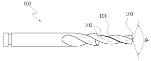
도 1은 본 발명에 따른 초경스텝드릴의 측면구성도.1 is a side configuration diagram of a carbide step drill according to the present invention.
도 2는 본 발명에 따른 초경스텝드릴의 정면도.Figure 2 is a front view of the carbide step drill according to the present invention.
도 3은 본 발명에 따른 초경스텝드릴의 사용상태도.Figure 3 is a state of use of the carbide step drill according to the present invention.
*** 도면의 주요 부분에 대한 부호의 설명 ****** Explanation of symbols for the main parts of the drawing ***
100 : 초경스텝드릴 101 : 드릴날100: carbide step drill 101: drill blade
102 : 스파이럴 홈 103 : 선단부102: spiral groove 103: distal end
104 : 마진부 200 : 피삭재104: margin 200: workpiece
201 : 예비구멍201: spare hole
본 발명은 예비구멍 가공된 비철재료의 사상구멍 가공용 초경스텝드릴에 관한 것으로, 더욱 상세하게는 피삭재를 가공할 때 직진도를 높이고, 칩배출을 원활히 하고자 한 것이다.BACKGROUND OF THE INVENTION 1. Field of the Invention The present invention relates to a carbide step drill for finishing holes in non-ferrous materials, which have been preliminarily processed, and more particularly, to improve straightness and smooth chip discharge when machining a workpiece.
일반적으로 다이캐스팅과 같은 공정을 통해 예비구멍이 가공된 비철재료로 된 피삭재에 사상구멍을 뚫을 때에는 초경 버니싱 드릴을 사용하고 있으나 이러한 초경 버니싱 드릴은 그 홈이 직선형으로 되어 있어 칩이 분쇄되어 배출되므로 칩배출이 원활하지 않고, 드릴링시 전체적인 절삭저항이 커지게 되어 돌발 파손 트러블이 발생되며, 절삭속도 및 이송속도가 늦어 작업시간이 많이 소요되는 단점이 있었다.Generally, the carbide burnishing drill is used to drill the finishing hole in the non-ferrous material, which has been preliminarily processed through die casting process. However, the carbide burnishing drill has a straight groove so that the chip is crushed and discharged. Therefore, chip discharge is not smooth, and overall cutting resistance is increased during drilling, and breakage breakage occurs, and cutting speed and feed speed are slow, and thus a lot of work time is required.
이를 감안하여 초경 버니싱 드릴을 대신하여 일반 초경스텝드릴을 사용하기도 하나, 이러한 일반 초경스텝드릴은 30°정도의 스파이럴 홈이 형성되어 있어 칩 배출은 양호하나 선단각이 130∼140°정도로 구성되므로 절삭토크가 매우 커 공구수명이 짧으며, 또한 드릴링되는 구멍의 내경과 접촉되는 마진부가 2개로 이루어지므로 직진성 및 방향성이 떨어지는 단점이 있었다.In consideration of this, a general carbide step drill may be used instead of a carbide burnishing drill. However, since the general carbide step drill has a spiral groove of about 30 °, chip discharge is good, but the tip angle is about 130 to 140 °. The cutting torque is very large, the tool life is short, and since two margin parts are in contact with the inner diameter of the drilled hole, the straightness and the directionality are inferior.
본 발명은 이러한 점을 감안하여 제안된 것으로, 일반 초경스텝드릴과 같이 30°정도의 스파이럴 홈을 형성하되, 그 선단각은 176 ± 2°정도로 구성하여 절삭토크를 작게 구현함으로써 드릴의 수명을 연장할 수 있으며, 마진부를 4개로 구성하여 직진성 및 방향성을 향상시킬 수 있는 예비구멍 가공된 비철 재료의 사상구멍 가공용 초경스텝드릴을 제공하고자 하는 것이다.The present invention has been proposed in view of this point, and forms a spiral groove of about 30 ° like a normal carbide step drill, and its tip angle is configured to about 176 ± 2 ° to extend the life of the drill by realizing the cutting torque. It is possible to provide, and to provide a carbide step drill for finishing holes of pre-punched non-ferrous material that can improve the straightness and direction by configuring four margins.
이하, 본 발명을 제시되는 실시예와 첨부된 도면에 따라 상세히 설명한다.Hereinafter, exemplary embodiments of the present invention will be described in detail with reference to the accompanying drawings.
도 1은 본 발명에 따른 초경스텝드릴의 측면구성도이고, 도 2는 본 발명에 따른 초경스텝드릴의 정면도이며, 도 3은 본 발명에 따른 초경스텝드릴의 사용상태 도이다.1 is a side configuration diagram of a carbide step drill according to the present invention, Figure 2 is a front view of the carbide step drill according to the present invention, Figure 3 is a state diagram of the carbide step drill according to the present invention.
도시된 바와 같이, 본 발명에 따른 초경스텝드릴(100)은 단차를 갖는 드릴날(101)의 사이에 2개의 스파이럴 홈(102)이 30°의 각도로 형성되고, 드릴날(101)의 선단부(103) 각도(θ)는 176 ± 2°로 구성되며, 드릴날(101)에는 마진부(104)가 4개 형성되어 이루어진 것이다.As shown, the
이와 같이 구성된 본 발명에 따른 초경스텝드릴의 작용을 설명하면 다음과 같다.Referring to the operation of the cemented carbide step drill according to the present invention configured as described above are as follows.
먼저, 다이캐스팅 등의 작업을 통해 예비구멍(201)이 형성되어 있는 비철재료로 된 피삭재(200)에 사상구멍을 내고자 할 때 본 발명에 따른 초경스텝드릴(100)을 사용하게 되면 최초 선단부(103)가 예비구멍(201)에 접촉되어 그 방향을 가이드하면서 드릴링이 이루어지게 된다.First, when the carbide step drill 100 according to the present invention is used to make a finishing hole in the
이때, 본 발명에 따른 초경스텝드릴(100)의 선단부(103)는 그 각도(θ)가 176 ± 2°로 구성되어 있어 예비구멍(201)과의 접촉시 종래 일반 초경스텝드릴의 선단각이 130∼140°로 구성된 것과 비교할 때 절삭토크가 작게 걸리게 되어 드릴의 수명을 연장할 수 있으며, 드릴날(101)의 사이에 30°각도의 2개의 스파이럴 홈(102)이 형성되어 있어 절삭된 칩이 바깥쪽으로 원활히 배출될 수 있는데, 배출되는 칩은 부서지지 않고 연결된 형상으로 배출이 이루어질 수 있어 그만큼 드릴의 절삭저항을 감소할 수 있는 것이다.At this time, the
또한, 본 발명에 따른 초경스텝드릴(100)은 그 드릴날(101)에 4개의 마진부(104)가 형성되어 있어 이러한 마진부(104)가 드릴링되는 사상구멍의 내경 전체면 과 접촉되어 회전되므로 직진성을 유지할 수 있어 드릴링되는 사상구멍의 방향이 직선형으로 형성될 수 있는 것이다.In addition, the
이상에서 설명한 바와 같이, 본 발명은 선단각을 종래에 비해 크게 적용한 것이므로 절삭토크가 작아지게 되어 드릴의 수명을 연장할 수 있음은 물론 직진성을 유지할 수 있고, 드릴날의 사이에 스파이럴 홈을 형성한 것이므로 칩배출이 용이하며, 4개의 마진부가 형성되어 있어 드릴링 방향을 정확하게 안내할 수 있어 고품질의 사상구멍 가공이 가능해지는 매우 유용한 효과가 있는 것이다.As described above, in the present invention, since the tip angle is larger than in the related art, the cutting torque is reduced, thereby extending the life of the drill, as well as maintaining the straightness, and forming a spiral groove between the drill blades. Since the chip is easy to discharge, and four margins are formed, the drilling direction can be accurately guided, so that high quality finishing holes can be processed.
Claims (1)
Priority Applications (1)
| Application Number | Priority Date | Filing Date | Title |
|---|---|---|---|
| KR1020050040012A KR100628885B1 (en) | 2005-05-13 | 2005-05-13 | Carbide step drill for finishing holes in non-ferrous materials |
Applications Claiming Priority (1)
| Application Number | Priority Date | Filing Date | Title |
|---|---|---|---|
| KR1020050040012A KR100628885B1 (en) | 2005-05-13 | 2005-05-13 | Carbide step drill for finishing holes in non-ferrous materials |
Related Child Applications (1)
| Application Number | Title | Priority Date | Filing Date |
|---|---|---|---|
| KR20-2005-0013503U Division KR200390853Y1 (en) | 2005-05-13 | 2005-05-13 | Carbide step drill to process final hole of material without steel having reserve hole |
Publications (1)
| Publication Number | Publication Date |
|---|---|
| KR100628885B1 true KR100628885B1 (en) | 2006-09-27 |
Family
ID=37628880
Family Applications (1)
| Application Number | Title | Priority Date | Filing Date |
|---|---|---|---|
| KR1020050040012A Expired - Lifetime KR100628885B1 (en) | 2005-05-13 | 2005-05-13 | Carbide step drill for finishing holes in non-ferrous materials |
Country Status (1)
| Country | Link |
|---|---|
| KR (1) | KR100628885B1 (en) |
Cited By (5)
| Publication number | Priority date | Publication date | Assignee | Title |
|---|---|---|---|---|
| CN103213179A (en) * | 2012-01-23 | 2013-07-24 | 艾温工业工具公司 | Step drill for wood |
| KR101498077B1 (en) * | 2014-04-28 | 2015-03-03 | 김준범 | Apparatus for Removing Burr Automatically |
| KR20190067395A (en) | 2017-12-07 | 2019-06-17 | 이승용 | Twist Drill for Precision Drilling |
| JP2021053783A (en) * | 2019-10-01 | 2021-04-08 | 三菱マテリアル株式会社 | Drill |
| KR102925381B1 (en) | 2025-09-08 | 2026-02-10 | 주식회사 정토엠엔티 | Fixture for roll chamfer |
-
2005
- 2005-05-13 KR KR1020050040012A patent/KR100628885B1/en not_active Expired - Lifetime
Cited By (7)
| Publication number | Priority date | Publication date | Assignee | Title |
|---|---|---|---|---|
| CN103213179A (en) * | 2012-01-23 | 2013-07-24 | 艾温工业工具公司 | Step drill for wood |
| US9156094B2 (en) | 2012-01-23 | 2015-10-13 | Irwin Industrial Tool Company | Step drill for wood |
| KR101498077B1 (en) * | 2014-04-28 | 2015-03-03 | 김준범 | Apparatus for Removing Burr Automatically |
| KR20190067395A (en) | 2017-12-07 | 2019-06-17 | 이승용 | Twist Drill for Precision Drilling |
| JP2021053783A (en) * | 2019-10-01 | 2021-04-08 | 三菱マテリアル株式会社 | Drill |
| JP7423965B2 (en) | 2019-10-01 | 2024-01-30 | 三菱マテリアル株式会社 | Drill |
| KR102925381B1 (en) | 2025-09-08 | 2026-02-10 | 주식회사 정토엠엔티 | Fixture for roll chamfer |
Similar Documents
| Publication | Publication Date | Title |
|---|---|---|
| JP5855813B2 (en) | Solid step drill | |
| CN102741014B (en) | Drill bit and manufacturing method thereof | |
| KR101514474B1 (en) | Drill | |
| JP2006150553A (en) | Drill | |
| JP2008093805A (en) | Drill | |
| WO2009118947A1 (en) | Gun drill | |
| US20120121351A1 (en) | Deep hole drill | |
| JP2004160651A (en) | Gundrill | |
| CN107206510A (en) | Single-edge deep-hole is bored | |
| JP2009255202A (en) | Drill head for cutting deep hole | |
| CN107262786A (en) | A kind of band stops section step drill and its manufacture method | |
| KR100628885B1 (en) | Carbide step drill for finishing holes in non-ferrous materials | |
| JP2009056534A (en) | Counterbore drill | |
| JP2008173727A (en) | Drill | |
| CN215786950U (en) | Compound tool for non-metal composite material | |
| US9085033B2 (en) | Drilling tool | |
| JP4468012B2 (en) | Rotating drill | |
| KR200390853Y1 (en) | Carbide step drill to process final hole of material without steel having reserve hole | |
| CN113020666A (en) | Compound tool for non-metal composite material | |
| JP4142930B2 (en) | Deep hole cutting tool | |
| KR101822517B1 (en) | Step drill bit | |
| JP4699526B2 (en) | Drill | |
| KR100990171B1 (en) | Twist drill reamer for the high speed machining of the difficult-to-cut materials | |
| JP2016144865A (en) | Processing method using drill and drill with coolant ejection hole | |
| CN210632991U (en) | Drilling, reaming and milling deep hole cavity machining tool |
Legal Events
| Date | Code | Title | Description |
|---|---|---|---|
| A201 | Request for examination | ||
| PA0109 | Patent application |
St.27 status event code: A-0-1-A10-A12-nap-PA0109 |
|
| PA0201 | Request for examination |
St.27 status event code: A-1-2-D10-D11-exm-PA0201 |
|
| E701 | Decision to grant or registration of patent right | ||
| PE0701 | Decision of registration |
St.27 status event code: A-1-2-D10-D22-exm-PE0701 |
|
| GRNT | Written decision to grant | ||
| PR0701 | Registration of establishment |
St.27 status event code: A-2-4-F10-F11-exm-PR0701 |
|
| PR1002 | Payment of registration fee |
St.27 status event code: A-2-2-U10-U11-oth-PR1002 Fee payment year number: 1 |
|
| PG1601 | Publication of registration |
St.27 status event code: A-4-4-Q10-Q13-nap-PG1601 |
|
| PR1001 | Payment of annual fee |
St.27 status event code: A-4-4-U10-U11-oth-PR1001 Fee payment year number: 4 |
|
| PR1001 | Payment of annual fee |
St.27 status event code: A-4-4-U10-U11-oth-PR1001 Fee payment year number: 5 |
|
| PR1001 | Payment of annual fee |
St.27 status event code: A-4-4-U10-U11-oth-PR1001 Fee payment year number: 6 |
|
| FPAY | Annual fee payment |
Payment date: 20120911 Year of fee payment: 7 |
|
| PR1001 | Payment of annual fee |
St.27 status event code: A-4-4-U10-U11-oth-PR1001 Fee payment year number: 7 |
|
| FPAY | Annual fee payment |
Payment date: 20131008 Year of fee payment: 8 |
|
| PR1001 | Payment of annual fee |
St.27 status event code: A-4-4-U10-U11-oth-PR1001 Fee payment year number: 8 |
|
| FPAY | Annual fee payment |
Payment date: 20140923 Year of fee payment: 9 |
|
| PR1001 | Payment of annual fee |
St.27 status event code: A-4-4-U10-U11-oth-PR1001 Fee payment year number: 9 |
|
| FPAY | Annual fee payment |
Payment date: 20150922 Year of fee payment: 10 |
|
| PR1001 | Payment of annual fee |
St.27 status event code: A-4-4-U10-U11-oth-PR1001 Fee payment year number: 10 |
|
| FPAY | Annual fee payment |
Payment date: 20160920 Year of fee payment: 11 |
|
| PR1001 | Payment of annual fee |
St.27 status event code: A-4-4-U10-U11-oth-PR1001 Fee payment year number: 11 |
|
| PR1001 | Payment of annual fee |
St.27 status event code: A-4-4-U10-U11-oth-PR1001 Fee payment year number: 12 |
|
| FPAY | Annual fee payment |
Payment date: 20180921 Year of fee payment: 13 |
|
| PR1001 | Payment of annual fee |
St.27 status event code: A-4-4-U10-U11-oth-PR1001 Fee payment year number: 13 |
|
| PR1001 | Payment of annual fee |
St.27 status event code: A-4-4-U10-U11-oth-PR1001 Fee payment year number: 14 |
|
| PR1001 | Payment of annual fee |
St.27 status event code: A-4-4-U10-U11-oth-PR1001 Fee payment year number: 15 |
|
| PR1001 | Payment of annual fee |
St.27 status event code: A-4-4-U10-U11-oth-PR1001 Fee payment year number: 16 |
|
| PR1001 | Payment of annual fee |
St.27 status event code: A-4-4-U10-U11-oth-PR1001 Fee payment year number: 17 |
|
| PR1001 | Payment of annual fee |
St.27 status event code: A-4-4-U10-U11-oth-PR1001 Fee payment year number: 18 |
|
| PN2301 | Change of applicant |
St.27 status event code: A-5-5-R10-R13-asn-PN2301 St.27 status event code: A-5-5-R10-R11-asn-PN2301 |
|
| PR1001 | Payment of annual fee |
St.27 status event code: A-4-4-U10-U11-oth-PR1001 Fee payment year number: 19 |
|
| PC1801 | Expiration of term |
St.27 status event code: N-4-6-H10-H14-oth-PC1801 Not in force date: 20250514 Ip right cessation event data comment text: Termination Category : EXPIRATION_OF_DURATION |
|
| R18 | Changes to party contact information recorded |
Free format text: ST27 STATUS EVENT CODE: A-5-5-R10-R18-OTH-X000 (AS PROVIDED BY THE NATIONAL OFFICE) |
|
| R18-X000 | Changes to party contact information recorded |
St.27 status event code: A-5-5-R10-R18-oth-X000 |