KR100607572B1 - Height adjustable manhole cover - Google Patents
Height adjustable manhole cover Download PDFInfo
- Publication number
- KR100607572B1 KR100607572B1 KR1020030067928A KR20030067928A KR100607572B1 KR 100607572 B1 KR100607572 B1 KR 100607572B1 KR 1020030067928 A KR1020030067928 A KR 1020030067928A KR 20030067928 A KR20030067928 A KR 20030067928A KR 100607572 B1 KR100607572 B1 KR 100607572B1
- Authority
- KR
- South Korea
- Prior art keywords
- manhole cover
- manhole
- height adjustment
- adjustment ring
- frame
- Prior art date
- Legal status (The legal status is an assumption and is not a legal conclusion. Google has not performed a legal analysis and makes no representation as to the accuracy of the status listed.)
- Expired - Fee Related
Links
Images


Classifications
-
- E—FIXED CONSTRUCTIONS
- E02—HYDRAULIC ENGINEERING; FOUNDATIONS; SOIL SHIFTING
- E02D—FOUNDATIONS; EXCAVATIONS; EMBANKMENTS; UNDERGROUND OR UNDERWATER STRUCTURES
- E02D29/00—Independent underground or underwater structures; Retaining walls
- E02D29/12—Manhole shafts; Other inspection or access chambers; Accessories therefor
- E02D29/14—Covers for manholes or the like; Frames for covers
- E02D29/1409—Covers for manholes or the like; Frames for covers adjustable in height or inclination
-
- E—FIXED CONSTRUCTIONS
- E02—HYDRAULIC ENGINEERING; FOUNDATIONS; SOIL SHIFTING
- E02D—FOUNDATIONS; EXCAVATIONS; EMBANKMENTS; UNDERGROUND OR UNDERWATER STRUCTURES
- E02D2200/00—Geometrical or physical properties
- E02D2200/11—Height being adjustable
Landscapes
- Engineering & Computer Science (AREA)
- Environmental & Geological Engineering (AREA)
- Life Sciences & Earth Sciences (AREA)
- General Life Sciences & Earth Sciences (AREA)
- Mining & Mineral Resources (AREA)
- Paleontology (AREA)
- Civil Engineering (AREA)
- General Engineering & Computer Science (AREA)
- Structural Engineering (AREA)
- Underground Structures, Protecting, Testing And Restoring Foundations (AREA)
Abstract
본 발명은 도로의 보수공사등에 의하여 지면을 덧씌우게 되는 경우 기존에 설치된 맨홀뚜껑의 위치에 비례하여 지면의 높이가 높아져 요철부를 형성하여 차량 주행시 대형사고의 발생을 미연에 방지하고자 발명된 것으로 상기 맨홀틀과 맨홀뚜껑의 사이에 높이 조절링을 회전식으로 체결함으로서 지면보다 낮은 위치에 있는 맨홀뚜껑의 위치를 간단하게 지면과 수평으로 조절이 가능한 것이다.The present invention has been invented in order to prevent the occurrence of large accidents when driving the vehicle by forming an uneven portion by increasing the height of the ground in proportion to the position of the existing manhole cover when the ground is covered by road repair work, etc. By rotationally fastening the height adjustment ring between the frame and the manhole cover, the position of the manhole cover at a lower position than the ground can be easily adjusted horizontally with the ground.
상기와 같이 제공된 높이 조절링은 상측에 측벽이 위치하고 하측에는 끼움벽이 위치하며 상기 측벽 하부와 끼움벽 상부에는 별도의 단턱으로 연결된 2단의 절곡부를 갖는 것으로 단턱의 내주연과 끼움벽의 외주연에 등간격으로 경사진 가이드 돌기를 돌출 형성하여 맨홀틀의 내주연과 맨홀뚜껑의 하부 외주연에 등간격으로 형성된 가이드 돌기와 회전식으로 체결가능하도록 발명한 것이다.The height adjustment ring provided as described above has a side wall at the upper side and a fitting wall at the lower side, and has two bent portions connected to the lower side of the side wall and the upper fitting wall by a separate step, and the inner circumference of the step and the outer circumference of the fitting wall. It is invented to be rotatably coupled to the guide projection formed at equal intervals on the inner circumference of the manhole frame and the lower outer circumference of the manhole cover by forming a guide projection inclined at equal intervals.
Description
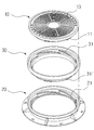
도 1은 본 발명의 분리 사시도1 is an exploded perspective view of the present invention
도 2는 본 발명의 결합 사시도2 is a perspective view of the combination of the present invention
도 3은 본 발명이 지면에 매립된 상태의 측단면도Figure 3 is a side cross-sectional view of the present invention embedded in the ground
도 4는 높이 조절링의 일측을 임의로 절개한 절개사시도Figure 4 is an incision cutaway arbitrarily cut one side of the height adjustment ring
도 5는 본 발명의 저면 분리 사시도5 is a bottom perspective view of the present invention
도 6은 맨홀뚜껑과 걸고리를 도시한 사용상태도Figure 6 is a state diagram using the manhole cover and hook
도 7은 복수개의 높이 조절링을 적층한 실시예 7 is an embodiment in which a plurality of height adjustment rings are stacked
도 8은 높이 조절링의 측벽을 연장시킨 상태의 실시예8 is an embodiment in which the side wall of the height adjustment ring is extended;
〈도면의 주요부분에 대한 부호의 간단한 설명〉 <Brief description of symbols for the main parts of the drawings>
1-맨홀 10-맨홀뚜껑 11,21,31,31'-가이드 돌기1-manhole 10-
12-멈춤돌기 13-연결공 14-걸고리12-Dump 13-Connection 14-hook
20-맨홀틀 30-높이 조절링 32-측벽20-manhole frame 30-height adjustment ring 32-side wall
33-끼움벽 34-단턱33-fitting wall 34-step
본 발명은 도로상에 위치한 맨홀을 보다 안전하게 관리하고 지면을 덧씌우는 도로의 보수공사시 기존에 사용되던 맨홀뚜껑과 맨홀틀사이에 높이 조절링을 체결하여 간단하게 맨홀뚜껑의 위치를 지면과 수평으로 조절 가능한 높이 조절링을 구비한 맨홀에 관한 것이다.The present invention is more securely manage the manhole located on the road and tighten the height adjustment ring between the manhole cover and the manhole frame that was used in the past during the repair work of the road to cover the ground simply position the position of the manhole cover horizontally with the ground A manhole having an adjustable height adjustment ring.
상기와 같은 목적으로 제공된 높이 조절링은 상측에 측벽을 형성하고 하측에는 끼움벽을 형성하며 상기 측벽의 하단부로부터 내측 수직방향으로 단턱이 연결되고 단턱의 내경 하부에는 역시 수직방향으로 끼움벽을 형성한 구조로서 상기 높이 조절링이 맨홀뚜껑과 맨홀틀사이에 용이하게 회전식으로 체결키 위하여 단턱의 내주연과 끼움벽의 외주연에는 등간격으로 복수개의 가이드 돌기가 경사지게 돌출 형성되어 맨홀뚜껑 하부의 가이드 돌기 및 맨홀틀 내주연의 가이드 돌기와 각각 회전식으로 체결토록 발명한 것이다.The height adjustment ring provided for the above purpose is to form a side wall at the upper side and the fitting wall at the lower side, the stepped portion is connected in the inner vertical direction from the lower end of the side wall, and also formed the fitting wall in the vertical direction at the lower end of the step. As a structure, a plurality of guide protrusions are formed to be inclined at equal intervals on the inner circumference of the step and the outer circumference of the fitting wall so that the height adjustment ring is easily rotated between the manhole cover and the manhole frame. And it is invented to be rotatably coupled to the guide projection of the inner periphery of the manhole frame respectively.
주지하다시피 종래에 사용되어 오던 대부분의 맨홀은 맨홀틀과 맨홀뚜껑의 외측에 복수개의 볼트체결공을 형성하여 상기 볼트체결공을 수직선상에 맞춘상태에서 볼트로 체결하는 구조와, 맨홀틀의 내주연에 소정의 홈부를 형성하고 상기 홈부와 체결가능한 걸림턱을 맨홀뚜껑의 하부에 형성하여 상기 걸림턱을 맨홀틀에 끼운상태에서 맨홀뚜껑을 일방향으로 회전하여 맨홀뚜껑을 고정하는 구조등이 주된 종래의 기술내용이다.As is well known, most manholes that have been used conventionally have a structure in which a plurality of bolt fastening holes are formed on the outside of the manhole frame and the manhole cover, and the bolt fastening holes are aligned in a vertical line to be fastened with bolts. The main conventional structure is to form a predetermined groove in the periphery and to form a locking jaw that can be fastened with the groove at the bottom of the manhole cover, and to rotate the manhole cover in one direction while the locking jaw is inserted into the manhole frame to fix the manhole cover. Description of the
그러나 상기 전자의 맨홀뚜껑은 볼트로 체결하여 맨홀뚜껑을 고정함에 따라 장기간 방치한 상태에서 맨홀뚜껑을 개방코자 볼트를 해지시 볼트가 외부에 노출된 상태로 구성됨에 따라 부식되기 쉬어 볼트의 해지 작업이 난해한 단점이 제기되고 후자의 맨홀뚜껑 역시 외부에 노출된 상태로 제공됨에 따라 이물질이 맨홀뚜껑의 홈부와 그 주변에 쉽게 끼워지게 되어 개폐가 용이하지 않은 문제점이 제기되는 것이며 상기 양자간의 맨홀뚜껑들은 도로상에서 발생하는 각종 문제점에 의하여 맨홀뚜껑을 개방한 상태에서 작업 후 맨홀뚜껑을 맨홀틀에 체결시 별도의 잠금작업을 진행함에 따라 불필요한 시간과 인력이 낭비되는 문제점이 제기된다.However, the manhole cover of the former is fastened by bolts to fix the manhole cover, so that the bolt is exposed to the outside when the manhole cover is opened for a long time and the bolt is exposed to the outside. Difficult drawbacks are raised and the latter manhole cover is also exposed to the outside, so that foreign matter is easily inserted into the grooves and the surroundings of the manhole cover, which makes it difficult to open and close the problem. According to various problems arising from the above, when the manhole cover is opened in the open state after the manhole cover is fastened to the manhole frame, a separate locking operation proceeds, a problem that wastes unnecessary time and manpower.
상기와 같은 문제점을 보완코자 발명된 것이 등록실용신안 제 298716호로서 상기 선출원된 발명은 맨홀틀의 하부 내주연에 약 3.5도의 경사각을 갖는 가이드 돌기가 6개로 구비되며 상기 가이드 돌기와 회전식으로 체결가능하도록 맨홀뚜껑의 하부 외주연에 역시 3.5도의 경사각을 갖는 가이드 돌기가 6개 구비되어 상호 회전식으로 체결함에 따라 체결작업에 따른 불필요한 문제점과 회전식으로 맨홀뚜껑이 개방됨에 따라 개방시 발생하는 문제점등을 해소하였으며 상기 맨홀틀의 가이드 돌기 하부에는 멈춤돌기를 형성하여 맨홀뚜껑을 일방향으로 회전하여 체결시 상기 멈춤돌기에 의하여 맨홀뚜껑의 회전이 자체적으로 정지가능하도록 발명된 것이다.In order to solve the above problems, the invention was registered as a Utility Model No. 298716, which is provided with six guide protrusions having an inclination angle of about 3.5 degrees on the lower inner circumference of the manhole frame, and are rotatably coupled with the guide protrusions. Six guide protrusions, which have an angle of inclination of 3.5 degrees, are also provided on the lower outer periphery of the manhole cover, thereby eliminating unnecessary problems due to the fastening operation and the problems caused when opening the manhole cover by rotation. A stop protrusion is formed below the guide protrusion of the manhole frame, and the manhole cover is rotated in one direction so that the rotation of the manhole cover can be stopped by itself by the stop protrusion.
그러나 상기와 같이 발명된 맨홀 역시 도로상에 발생하는 각종 문제점에 따른 아스팔트를 덧씌우는 도로포장내지 보수작업시 지면의 높이가 기존보다 높아져 지면과 맨홀뚜껑간에 요철부가 형성되어 차량주행시 각종 안전사고가 발생하는 것을 미연에 방지하고자 맨홀틀 자체를 재설치하는 작업을 진행하는 것으로 상기 작업은 차량의 통행지연과 공사기간의 장기화에 따른 공사비가 상승하는 문제점을 유발하나 상기 선출원된 발명은 그에 대한 대응이 부적절하여 별도의 해결방안이 요 원한 것이다.However, the manhole invented as described above also has a higher height than the conventional ground pavement or maintenance work overlaid with asphalt according to various problems occurring on the road, and irregularities are formed between the ground and the manhole cover, resulting in various safety accidents when driving a vehicle. In order to prevent this from happening, the work of reinstalling the manhole frame itself is carried out, which causes a problem that the construction cost increases due to the delay of the traffic and the prolongation of the construction period, but the above-mentioned invention does not respond appropriately. A separate solution is required.
본 발명은 상기와 같은 문제점을 해소코자 상측에 측벽이 위치하고 하측에는 끼움벽이 위치하며 상기 측벽 하부와 끼움벽 상부에는 별도의 단턱으로 연결된 2단의 절곡부를 갖는 높이 조절링을 안출한 것으로 상기 높이 조절링의 단턱 내주연과 끼움벽 외주연에는 맨홀틀과 맨홀뚜껑에 등간격으로 돌출 형성된 가이드 돌기와 체결가능한 가이드 돌기가 각각 제공되어 맨홀틀의 내주연에 높이 조절링의 끼움부를 체결하고 측벽의 내주연에 맨홀뚜껑을 체결함으로서 맨홀뚜껑의 위치를 간단하게 지면과 수평으로 조절가능한 높이 조절링을 안출한 것이다. The present invention solves the above problems, the side wall is located on the upper side and the fitting wall is located on the lower side and the height adjustment ring having a two-step bent portion connected to a separate step on the lower side of the side wall and the fitting wall. The inner periphery of the adjustment ring and the outer periphery of the fitting wall are provided with guide protrusions and fastening guide protrusions formed at equal intervals on the manhole frame and the manhole cover, respectively, to fasten the fitting portion of the height adjustment ring on the inner periphery of the manhole frame, By tightening the manhole cover on the periphery, the position of the manhole cover can be easily laid out with a height adjustment ring that can be adjusted horizontally with the ground.
이하 본 발명의 구성요소를 설명하면 다음과 같다.Hereinafter, the components of the present invention will be described.
맨홀틀(20)과 맨홀뚜껑(10)사이에 체결하여 맨홀뚜껑(10)의 높이를 조절하기 위한 목적으로 구성된 높이 조절링(30)은 상부에 측벽(32)이 종방향으로 위치하고 측벽(32)의 하부 내측에는 횡방향으로 2단의 절곡부가 형성된 단턱(34)이 위치하며 상기 단턱(34)의 내측 하부에는 종방향으로 끼움벽(33)을 형성하는 중앙이 관통된 링형상으로서, 상기 측벽(32)의 내경은 맨홀뚜껑(10)을 수용가능한 직경으로 구성하고 상기 단턱(34)의 내주연에는 등간격으로 6개의 가이드 돌기(31)가 약 3.5도 경사진 각도로 돌출 형성되며, 끼움벽(33)의 외주연은 맨홀틀(20)의 하부 내경에 수용가능한 직경으로 구성하고 상기 끼움벽(33)의 외주연에는 역시 등간격으로 6개의 가이드 돌기(31')가 약 3.5도 경사진 각도로 돌출 형성된 것이다.The
상기와 같이 구성된 높이 조절링(30)의 측벽(32) 내주연에는 맨홀뚜껑(10)이 체결되고 끼움벽(33)의 외주연에는 맨홀틀(20)과 각각 체결키 위하여 상기 맨홀뚜껑(10)의 하측 외주연과 맨홀틀(20)의 내주연에는 높이 조절링(30)에 형성된 가이드 돌기(11,21)와 각각 대응 가능한 가이드 돌기(31,31')를 형성하여 회전식으로 체결하는 것이며, 상기 높이 조절링(30)은 측벽(32)의 높이를 연장하거나 복수개의 높이 조절링(30)을 적층함에 따라 종속적으로 체결되는 맨홀뚜껑(10)의 위치를 조절 가능하도록 구성된 것이다.The
또한 상기 맨홀뚜껑(10)의 상부 일측에 이동구 연결공(13)을 형성하고 임의의 가이드 돌기(11) 상측에는 멈춤돌기(12)를 형성하여 도 3의 결합상태 단면구조에서 보는 것과 같이, 맨홀틀(10)에 대해 회전 체결되어 높이 조절된 높이 조절링(30)으로 맨홀뚜껑(10)을 체결하면 상기 높이 조절링(30)의 측벽(32) 내주연에 회전식으로 상기 맨홀뚜껑(10)의 회전 체결되며, 이때 맨홀뚜껑(10)은 멈춤돌기(12)에 의하여 높이 조절링(30)과 동일 높이로 안정되게 고정될 수 있다.
즉, 맨홀뚜껑(10)의 가이드돌기(11)가 높이 조절링(30)의 가이드돌기(21)를 따라 안내되어 회전 체결되면서 상기 맨홀뚜껑(10)에 형성된 멈춤돌기(12)에 의해 더이상 회전이 진행되지 않고 일정 위치에서 안정되게 고정될 수 있으며, 물론 멈춤돌기(12)에 의한 상기 맨홀뚜껑(10)과 높이 조절링(30) 간의 체결높이가 동일 선상에서 이루어질 수 있도록 제품의 성형이 이루어짐은 당연하다. 아울러 도면에서는 생략되었으나 이들 구성요소들 간에 외부로부터 보다 효과적으로 충격 흡수 및 기밀을 유지할 수 있는 패킹수단이 설치될 수 있으나, 본 발명의 구조적인 특성상 패킹수단 없이도 외부 충격에 대해 별다른 하자 없이 유동되지 않고 결합상태가 유지될 수 있다.In addition, the movable
That is, the
상술한 바를 이하 첨부된 도면에 의하여 보다 상세히 설명하면 다음과 같다.When described above in more detail by the accompanying drawings as follows.
도 1은 맨홀틀(20)과 높이 조절링(30) 및 맨홀뚜껑(10)을 각각 분리한 상태의 분리사시도이고 도 2는 맨홀틀(20)과 맨홀뚜껑(10)사이에 높이 조절링(30)이 체결된 상태의 결합사시도이며 도 3은 맨홀틀(20)이 지면에 매립된 상태의 측단면도를 도시한 것이고 도 4는 본 발명의 요부인 높이 조절링(30)의 일측을 임의로 절개한 절개사시도이다.1 is an exploded perspective view of a state in which the
상기 도시된 도면과 같이 맨홀틀(20)의 내주연에는 약 3.5도의 각도를 갖는 6개의 가이드 돌기(21)를 형성한 것이며 맨홀뚜껑(10)의 하부 외주연은 맨홀틀(20)과 원할히 체결가능코자 맨홀틀(20)의 내주연보다 적은 직경으로 구성하며 상기 외 주연에는 약 3.5도의 각도를 갖는 6개의 가이드 돌기(11)를 등간격으로 돌출 형성하고 상기 임의의 가이드 돌기(11) 상측에는 멈춤돌기(12)를 돌출 형성하여 상호 가이드 돌기(11,21)가 회전식으로 체결가능하며 일정부분 회전시는 상기 멈춤돌기(12)에 의하여 맨홀뚜껑(10)의 회전이 정지되도록 구성된 것이다.As shown in the drawing, the inner periphery of the
상기와 같은 구조로 체결되는 통상적인 맨홀(1)에 있어서 맨홀뚜껑(10)의 위치를 상승시코자 제공되는 높이 조절링(30)의 측벽(32) 및 단턱(34) 내주연은 맨홀틀(20)의 내주연과 동일하게 구성하며 끼움벽(33)의 외주연은 맨홀뚜껑(10)의 하부 외주연과 동일하게 구성하여 상기 맨홀틀(20) 내주연에 높이 조절링(30)의 끼움벽(33)을 회전식으로 체결하고 상기 높이 조절링(30)의 단턱(34) 내주연에는 맨홀뚜껑(10)이 회전식으로 체결되는 것으로 상기 체결구조를 보조키 위하여 내외주연에 위치한 가이드 돌기(11,21,31,31')가 상호 맞물린 상태에서 경사부를 따라 회전하도록 구성된 것이다In the
또한 첨부된 도 5는 맨홀뚜껑(10)을 맨홀틀(20) 및 높이 조절링(30)과 분리한 상태를 저면에서 도시한 저면상태 분리사시도이고 도 6은 상기 맨홀뚜껑(10)과 걸고리(14)를 도시한 사용상태도로서 맨홀뚜껑(10)에 위치한 임의의 가이드 돌기(11) 상부 일측에 멈춤돌기(12)를 형성하고 맨홀뚜껑(10)의 상측면에는 상기 맨홀뚜껑(10)을 회전 및 이동하기 위한 보조수단으로 이동구 연결공(13)을 형성한 것이며, 상기 연결공(13) 하부에 도시한 걸고리(14)는 맨홀뚜껑(10)을 이동하거나 높이 조절링(30)에 체결 또는 분리시 편리를 제공키 위한 것으로 연결공(13)에 끼워 회전함으로서 높이 조절링(30)의 단턱(34) 내주연에 맨홀뚜껑(10)을 체결 또는 분리하는 것이고, 상기 멈춤돌기(12)에 의하여 맨홀뚜껑(10)이 높이 조절링(30)의 가이드 돌기(31)와 체결시 적정한 위치를 유지하도록 구성한 것이며 도 7은 복수개의 높이 조절링(30)이 연속적으로 적층시킨 상태를 도시한 것으로서 상기 높이 조절링(30)의 측벽(32) 내주연의 직경은 타 높이 조절링(30)의 끼움벽(33) 외주연의 직경을 수용할 수 있는 크기의 직경을 유지하는 것이며 상기 내주연과 외주연에 각각 형성된 가이드 돌기(31,31')는 상호 대응되는 위치에 형성되어 회전식으로 체결이 가능한 구조를 갖는 것이며 도 8은 높이 조절링(30)의 측벽(32)을 연장시킨 상태를 도시한 것으로 상기와 같이 측벽(32)의 높이를 연장함에 따라 다수개의 높이 조절링(30)을 축적할 필요가 없이 단수개의 높이 조절링(30)을 이용하여 맨홀뚜껑(10)의 높이를 지면과 수평으로 조절이 가능하도록 구성한 것이다.In addition, Figure 5 is a bottom perspective view showing the state separated from the
본 발명의 효과를 설명하면 다음과 같다.The effect of the present invention will be described as follows.
도로의 자체적인 결함이나 보수공사등에 의하여 지면을 덧씌우게 되는 경우 기존에 설치된 맨홀뚜껑의 위치에 비례하여 지면의 높이가 높아져 요철부를 형성하여 대형사고의 발생우려가 제기되는 것으로 이를 보수하기 위하여 종전과 같이 맨홀틀 자체를 재설치하는 경우 차량의 통행지연 및 공사기간의 장기화에 따른 공사비가 상승하는 문제점이 발생하던 것을 본원 발명에서 기술된 높이 조절링을 이용하여 맨홀틀과 맨홀뚜껑사이에 체결하여 맨홀뚜껑의 위치를 지면과 수평으로 제공함으로서 공사비와 공사기간을 단축하고 불필요한 인력낭비를 절감가능한 효과를 제공한다. When the ground is overlaid due to the road's own defect or repair work, the height of the ground is increased in proportion to the position of the manhole cover that is already installed, resulting in the formation of irregularities, resulting in the occurrence of large accidents. In case of re-installing the manhole frame itself, the construction cost increases due to the delay of the traffic and the prolongation of the construction period, and the manhole cover is fastened between the manhole frame and the manhole cover using the height adjustment ring described in the present invention. By providing the location of the machine horizontally with the ground, it reduces the cost of construction and construction period and provides unnecessary effect on unnecessary waste of manpower.
또한 상기와 같이 발명된 맨홀뚜껑의 가이드 돌기 상측에 멈춤돌기를 형성함으로서 맨홀뚜껑이 맨홀틀내지 높이조절링과 회전체결시 멈춤돌기에 의하여 맨홀뚜껑의 회전이 정지하는 것으로 상기 멈춤돌기를 맨홀뚜껑에 형성함으로서 사용자의 부주의등에 의하여 멈춤돌기가 파손시에도 종래와 같이 멈춤돌기가 구비된 맨홀틀을 교체하는 것이 아니라 간단히 맨홀뚜껑만 교체하여 재사용이 가능한 것이다.
In addition, by forming a stopper on the upper guide protrusion of the manhole cover invented as described above, the manhole cover is stopped by the manhole frame to the height adjustment ring and the stopper when the rotation is fastened. By forming, even when the stopper breaks due to carelessness of the user, it is possible to reuse by simply replacing the manhole cover, instead of replacing the manhole frame provided with the stopper as in the prior art.
Claims (3)
Priority Applications (1)
| Application Number | Priority Date | Filing Date | Title |
|---|---|---|---|
| KR1020030067928A KR100607572B1 (en) | 2003-09-30 | 2003-09-30 | Height adjustable manhole cover |
Applications Claiming Priority (1)
| Application Number | Priority Date | Filing Date | Title |
|---|---|---|---|
| KR1020030067928A KR100607572B1 (en) | 2003-09-30 | 2003-09-30 | Height adjustable manhole cover |
Related Child Applications (1)
| Application Number | Title | Priority Date | Filing Date |
|---|---|---|---|
| KR20-2003-0030843U Division KR200337106Y1 (en) | 2003-09-30 | 2003-09-30 | The manhole cover that the level control is possible |
Publications (2)
| Publication Number | Publication Date |
|---|---|
| KR20050031690A KR20050031690A (en) | 2005-04-06 |
| KR100607572B1 true KR100607572B1 (en) | 2006-08-03 |
Family
ID=37236510
Family Applications (1)
| Application Number | Title | Priority Date | Filing Date |
|---|---|---|---|
| KR1020030067928A Expired - Fee Related KR100607572B1 (en) | 2003-09-30 | 2003-09-30 | Height adjustable manhole cover |
Country Status (1)
| Country | Link |
|---|---|
| KR (1) | KR100607572B1 (en) |
Families Citing this family (4)
| Publication number | Priority date | Publication date | Assignee | Title |
|---|---|---|---|---|
| KR100835937B1 (en) * | 2007-07-19 | 2008-06-09 | 김진오 | Manhole Cover Coupling Device |
| KR100907040B1 (en) * | 2008-08-22 | 2009-07-09 | 김경호 | Height Adjustable Manhole |
| KR102210527B1 (en) | 2019-04-08 | 2021-01-29 | 이정민 | Lift supporting assembly for manhole |
| US11053658B2 (en) | 2019-09-19 | 2021-07-06 | Trevor Brien | Height adjustment mechanism for a manhole assembly and manhole assembly comprising the same |
-
2003
- 2003-09-30 KR KR1020030067928A patent/KR100607572B1/en not_active Expired - Fee Related
Also Published As
| Publication number | Publication date |
|---|---|
| KR20050031690A (en) | 2005-04-06 |
Similar Documents
| Publication | Publication Date | Title |
|---|---|---|
| US5628152A (en) | Adjustable manhole cover support with shield | |
| US6695526B2 (en) | Adjustable manhole apparatus | |
| KR102134641B1 (en) | Adjust height for raise ring manhole cover | |
| KR100607572B1 (en) | Height adjustable manhole cover | |
| KR200337106Y1 (en) | The manhole cover that the level control is possible | |
| KR100336293B1 (en) | manhole | |
| KR20220063671A (en) | Manhole cover opening and closing structure with screw | |
| KR100362512B1 (en) | A manhole whose lid has a device for separation prevention | |
| KR101873320B1 (en) | Manhole locking device using lock guide ring | |
| KR20090001343A (en) | Manhole Assembly with Lock | |
| KR20130035403A (en) | Manhole assembly having locking device for manhole cap | |
| KR100845570B1 (en) | Manhole cover for rainwater prevention | |
| KR101280274B1 (en) | Jointing device for man hole cover | |
| KR100942727B1 (en) | Height adjustment manhole cover | |
| KR200221892Y1 (en) | Manhole | |
| KR200417562Y1 (en) | Height Adjustable Replacement Manholes | |
| KR200309979Y1 (en) | locked device for manhole cover | |
| KR200371881Y1 (en) | Over lap ring of iron manhole cover | |
| KR200383421Y1 (en) | A fixing equipment of a manhole lid | |
| KR20210001841U (en) | Pulling up ring of manhole | |
| KR101350472B1 (en) | Manhole cover have a locking apparatus and manhole frame | |
| KR100511465B1 (en) | Manhole cover assembly with locking means | |
| KR200274875Y1 (en) | An opening and shutting apparatus for a manhole cover | |
| KR20010067025A (en) | A manhole formed connecting tool for preventing of cover separating | |
| KR200309994Y1 (en) | A manhole with means preventing from a seperation |
Legal Events
| Date | Code | Title | Description |
|---|---|---|---|
| A201 | Request for examination | ||
| PA0109 | Patent application |
St.27 status event code: A-0-1-A10-A12-nap-PA0109 |
|
| PA0201 | Request for examination |
St.27 status event code: A-1-2-D10-D11-exm-PA0201 |
|
| PN2301 | Change of applicant |
St.27 status event code: A-3-3-R10-R13-asn-PN2301 St.27 status event code: A-3-3-R10-R11-asn-PN2301 |
|
| R17-X000 | Change to representative recorded |
St.27 status event code: A-3-3-R10-R17-oth-X000 |
|
| PG1501 | Laying open of application |
St.27 status event code: A-1-1-Q10-Q12-nap-PG1501 |
|
| E902 | Notification of reason for refusal | ||
| PE0902 | Notice of grounds for rejection |
St.27 status event code: A-1-2-D10-D21-exm-PE0902 |
|
| T11-X000 | Administrative time limit extension requested |
St.27 status event code: U-3-3-T10-T11-oth-X000 |
|
| E13-X000 | Pre-grant limitation requested |
St.27 status event code: A-2-3-E10-E13-lim-X000 |
|
| P11-X000 | Amendment of application requested |
St.27 status event code: A-2-2-P10-P11-nap-X000 |
|
| P13-X000 | Application amended |
St.27 status event code: A-2-2-P10-P13-nap-X000 |
|
| E701 | Decision to grant or registration of patent right | ||
| PE0701 | Decision of registration |
St.27 status event code: A-1-2-D10-D22-exm-PE0701 |
|
| GRNT | Written decision to grant | ||
| N231 | Notification of change of applicant | ||
| PN2301 | Change of applicant |
St.27 status event code: A-5-5-R10-R13-asn-PN2301 St.27 status event code: A-5-5-R10-R11-asn-PN2301 |
|
| PR0701 | Registration of establishment |
St.27 status event code: A-2-4-F10-F11-exm-PR0701 |
|
| PR1002 | Payment of registration fee |
St.27 status event code: A-2-2-U10-U11-oth-PR1002 Fee payment year number: 1 |
|
| PG1601 | Publication of registration |
St.27 status event code: A-4-4-Q10-Q13-nap-PG1601 |
|
| PN2301 | Change of applicant |
St.27 status event code: A-5-5-R10-R11-asn-PN2301 |
|
| PR1001 | Payment of annual fee |
St.27 status event code: A-4-4-U10-U11-oth-PR1001 Fee payment year number: 4 |
|
| PR1001 | Payment of annual fee |
St.27 status event code: A-4-4-U10-U11-oth-PR1001 Fee payment year number: 5 |
|
| R18-X000 | Changes to party contact information recorded |
St.27 status event code: A-5-5-R10-R18-oth-X000 |
|
| R18-X000 | Changes to party contact information recorded |
St.27 status event code: A-5-5-R10-R18-oth-X000 |
|
| R18-X000 | Changes to party contact information recorded |
St.27 status event code: A-5-5-R10-R18-oth-X000 |
|
| PN2301 | Change of applicant |
St.27 status event code: A-5-5-R10-R13-asn-PN2301 St.27 status event code: A-5-5-R10-R11-asn-PN2301 |
|
| PR1001 | Payment of annual fee |
St.27 status event code: A-4-4-U10-U11-oth-PR1001 Fee payment year number: 6 |
|
| PR1001 | Payment of annual fee |
St.27 status event code: A-4-4-U10-U11-oth-PR1001 Fee payment year number: 7 |
|
| FPAY | Annual fee payment |
Payment date: 20130625 Year of fee payment: 8 |
|
| PR1001 | Payment of annual fee |
St.27 status event code: A-4-4-U10-U11-oth-PR1001 Fee payment year number: 8 |
|
| PN2301 | Change of applicant |
St.27 status event code: A-5-5-R10-R13-asn-PN2301 St.27 status event code: A-5-5-R10-R11-asn-PN2301 |
|
| FPAY | Annual fee payment |
Payment date: 20140627 Year of fee payment: 9 |
|
| PR1001 | Payment of annual fee |
St.27 status event code: A-4-4-U10-U11-oth-PR1001 Fee payment year number: 9 |
|
| PR1001 | Payment of annual fee |
St.27 status event code: A-4-4-U10-U11-oth-PR1001 Fee payment year number: 10 |
|
| FPAY | Annual fee payment |
Payment date: 20160616 Year of fee payment: 11 |
|
| PR1001 | Payment of annual fee |
St.27 status event code: A-4-4-U10-U11-oth-PR1001 Fee payment year number: 11 |
|
| P22-X000 | Classification modified |
St.27 status event code: A-4-4-P10-P22-nap-X000 |
|
| FPAY | Annual fee payment |
Payment date: 20170613 Year of fee payment: 12 |
|
| PR1001 | Payment of annual fee |
St.27 status event code: A-4-4-U10-U11-oth-PR1001 Fee payment year number: 12 |
|
| LAPS | Lapse due to unpaid annual fee | ||
| PC1903 | Unpaid annual fee |
St.27 status event code: A-4-4-U10-U13-oth-PC1903 Not in force date: 20180726 Payment event data comment text: Termination Category : DEFAULT_OF_REGISTRATION_FEE |
|
| PC1903 | Unpaid annual fee |
St.27 status event code: N-4-6-H10-H13-oth-PC1903 Ip right cessation event data comment text: Termination Category : DEFAULT_OF_REGISTRATION_FEE Not in force date: 20180726 |
|
| PN2301 | Change of applicant |
St.27 status event code: A-5-5-R10-R13-asn-PN2301 St.27 status event code: A-5-5-R10-R11-asn-PN2301 |