KR100559851B1 - Stabilizer for Hybrid Electric Vehicles - Google Patents
Stabilizer for Hybrid Electric Vehicles Download PDFInfo
- Publication number
- KR100559851B1 KR100559851B1 KR1020030060573A KR20030060573A KR100559851B1 KR 100559851 B1 KR100559851 B1 KR 100559851B1 KR 1020030060573 A KR1020030060573 A KR 1020030060573A KR 20030060573 A KR20030060573 A KR 20030060573A KR 100559851 B1 KR100559851 B1 KR 100559851B1
- Authority
- KR
- South Korea
- Prior art keywords
- vehicle
- hybrid
- wheel
- stabilizer
- driving motor
- Prior art date
- Legal status (The legal status is an assumption and is not a legal conclusion. Google has not performed a legal analysis and makes no representation as to the accuracy of the status listed.)
- Expired - Fee Related
Links
Images



Classifications
-
- B—PERFORMING OPERATIONS; TRANSPORTING
- B60—VEHICLES IN GENERAL
- B60W—CONJOINT CONTROL OF VEHICLE SUB-UNITS OF DIFFERENT TYPE OR DIFFERENT FUNCTION; CONTROL SYSTEMS SPECIALLY ADAPTED FOR HYBRID VEHICLES; ROAD VEHICLE DRIVE CONTROL SYSTEMS FOR PURPOSES NOT RELATED TO THE CONTROL OF A PARTICULAR SUB-UNIT
- B60W20/00—Control systems specially adapted for hybrid vehicles
-
- B—PERFORMING OPERATIONS; TRANSPORTING
- B60—VEHICLES IN GENERAL
- B60W—CONJOINT CONTROL OF VEHICLE SUB-UNITS OF DIFFERENT TYPE OR DIFFERENT FUNCTION; CONTROL SYSTEMS SPECIALLY ADAPTED FOR HYBRID VEHICLES; ROAD VEHICLE DRIVE CONTROL SYSTEMS FOR PURPOSES NOT RELATED TO THE CONTROL OF A PARTICULAR SUB-UNIT
- B60W2510/00—Input parameters relating to a particular sub-units
- B60W2510/20—Steering systems
- B60W2510/207—Oversteer or understeer
-
- B—PERFORMING OPERATIONS; TRANSPORTING
- B60—VEHICLES IN GENERAL
- B60Y—INDEXING SCHEME RELATING TO ASPECTS CROSS-CUTTING VEHICLE TECHNOLOGY
- B60Y2200/00—Type of vehicle
- B60Y2200/90—Vehicles comprising electric prime movers
- B60Y2200/92—Hybrid vehicles
Landscapes
- Engineering & Computer Science (AREA)
- Automation & Control Theory (AREA)
- Transportation (AREA)
- Mechanical Engineering (AREA)
- Vehicle Body Suspensions (AREA)
- Electric Propulsion And Braking For Vehicles (AREA)
- Regulating Braking Force (AREA)
Abstract
본 발명은 하이브리드 전기식 차량의 안정조정장치에 관한 것으로서, 각 차륜마다 구비되어 회생 제동과 동력 보조가 가능하도록 하는 하이브리드 주행용 모터와; 차량의 주행 상태를 감지하는 주행상태 감지수단과; 상기 주행상태 감지수단으로부터 입력된 신호를 연산하여 차량의 오버스티어나 언더스티어 경향을 판단하여 상기 하이브리드 주행용 모터를 제어하는 제어 수단을 포함하여 구성됨으로써, 별도의 브레이크 액츄에이터가 필요 없게 되어 연비 향상과 함께 배기를 절감할 수 있고, 간단한 구조로 차량의 선회 안정성을 보다 신속하게 확보할 수 있는 효과를 제공하게 된다.The present invention relates to a stabilizer for a hybrid electric vehicle, comprising: a hybrid driving motor provided for each wheel to enable regenerative braking and power assistance; Driving state detecting means for detecting a driving state of the vehicle; It is configured to include a control means for controlling the hybrid driving motor by determining the oversteer or understeer tendency of the vehicle by calculating the signal input from the driving state detection means, thereby eliminating the need for a separate brake actuator Along with this, the exhaust gas can be reduced, and the simple structure provides the effect of ensuring the vehicle's turning stability more quickly.
배터리, 발전기, 하이브리드, 모터, 변속기, 엔진Battery, alternator, hybrid, motor, transmission, engine
Description
도 1은 차량 선회시 언더 스티어나 오버 스티어의 주행 상태를 나타낸 참고도,1 is a reference diagram showing the driving state of the understeer or oversteer when turning the vehicle,
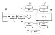
도 2는 본 발명에 따른 하이브리드 전기식 차량의 안정조정장치가 도시된 블록 구성도,2 is a block diagram showing a stabilizer of the hybrid electric vehicle according to the present invention;
도 3은 본 발명에서 차량의 언더 스티어, 오버 스티어 발생시의 억제 상태를 나타낸 참고도,3 is a reference diagram showing a suppression state when understeer or oversteer occurs in a vehicle according to the present invention;
도 4는 본 발명에 따른 차량의 안정조정 제어 흐름도이다.4 is a flow chart for controlling stability of a vehicle according to the present invention.
<도면의 주요 부분에 대한 부호의 설명><Explanation of symbols for the main parts of the drawings>
10 : 엔진 12 : 변속기 10
15, 15' : 차륜 20 : 발전기 15, 15 ': wheel 20: generator
30 : 배터리 40 : 하이브리드 주행용 모터 30: battery 40: hybrid driving motor
50 : 모터 제어 유닛 50: motor control unit
본 발명은 하이브리드 전기식 차량의 안정조정장치에 관한 것으로서, 특히 각 바퀴에 하이브리드 주행용 모터를 이용하여 차량의 선회 안정성을 보다 신속하게 확보할 수 있도록 한 하이브리드 전기식 차량의 안정조정장치에 관한 것이다.BACKGROUND OF THE INVENTION 1. Field of the Invention The present invention relates to a stabilizer for a hybrid electric vehicle, and more particularly, to a stabilizer for a hybrid electric vehicle, by which a hybrid driving motor is used on each wheel to more quickly secure turning stability of a vehicle.
일반적으로 차량의 안정조정장치(VSC-Vehicle Stability Control-System)는 차량의 선회 안정성을 확보하기 위한 시스템으로, 스티어링 조작에 있어서 노면상황이나 차속, 긴급 선회 등의 여러 요인으로 인하여 전륜, 또는 후륜, 또는 어느 한 바퀴에서 나타나는 미끄러짐을 방지하여 안정적인 선회가 되도록 하는 시스템이다.In general, the VSC-Vehicle Stability Control-System is a system for securing the vehicle's turning stability.The steering wheel controls the front wheel or the rear wheel due to various factors such as road conditions, vehicle speed, and emergency turning. Or it is a system to make a stable turning by preventing the slipping appearing in any one wheel.
이는 요-레이트(yaw-rate) 센서와 가속 센서, 각 차륜 속도 센서 등에 의해 얻은 신호에 의하여 각 바퀴마다의 브레이크 액츄에이터에 제어신호를 보내어 제동력을 가함으로써 도 1에 도시된 바와 같이 오버스티어(Over-Steer)나 언더스티어(Under-Steer)를 방지하여 정상 주행할 수 있는 구조로 되어 있다. This is achieved by applying a braking force by sending a control signal to the brake actuator for each wheel based on signals obtained by the yaw-rate sensor, the acceleration sensor, and the wheel speed sensor. -It is structured to drive normally by preventing Steer or Under Steer.
그러나, 상기와 같은 종래 기술의 차량의 안정조정장치는 각 바퀴마다의 제동력을 제어하기 위하여 별도의 브레이크 액츄에이터가 각 바퀴마다 따로 필요하기 때문에 안정 조정 구조가 복잡하고, 또한 제어가 어려울 뿐만 아니라, 제동력에 의하여만 안정성을 구현하는 만큼 상당한 동력의 손실이 발생하는 수동적인 제어방식이라는 문제점이 있다.However, the above-described stabilization device for a vehicle of the prior art requires a separate brake actuator for each wheel to control the braking force for each wheel, so that the stability adjustment structure is complicated and difficult to control. There is a problem of a passive control method that generates a significant power loss as it implements stability only.
본 발명은 상기한 문제점을 해결하기 위하여 안출된 것으로서, 각 차륜에 하이브리드 주행용 모터를 구비하여 차량의 주행 조건에 따라 각 차륜에 별도로 회생 제동과 동력 보조를 실행할 수 있도록 구성함으로써 간단한 구조로 차량의 선회 안정성을 보다 신속하게 확보할 수 있도록 하는 하이브리드 전기식 차량의 안정조정장치를 제공하는 데 목적이 있다.SUMMARY OF THE INVENTION The present invention has been made to solve the above problems, and is provided with a hybrid driving motor on each wheel so that each wheel can perform regenerative braking and power assistance separately according to the driving conditions of the vehicle. It is an object of the present invention to provide a stabilizer for a hybrid electric vehicle, which enables to secure turning stability more quickly.
상기한 과제를 실현하기 위한 본 발명에 따른 하이브리드 전기식 차량의 안정조정장치는, 각 차륜마다 구비되어 회생 제동과 동력 보조가 가능하도록 하는 하이브리드 주행용 모터와, 가속도 센서와 요 레이트 센서와 조타각 센서와 차륜 속도 센서 및 브레이크압 감지 센서를 포함하도록 구성되어 차량의 주행 상태를 감지하는 주행상태 감지수단과, 상기 주행상태 감지수단으로부터 입력된 신호를 연산하여 차량의 오버스티어나 언더스티어의 경향에 따라 상기 하이브리드 주행용 모터의 구동을 각각 독립적으로 제어하는 모터제어유닛을 포함하여 이루어지는 것을 특징으로 한다.A hybrid electric vehicle stabilization adjusting device according to the present invention for realizing the above object is a hybrid driving motor which is provided for each wheel to enable regenerative braking and power assistance, an acceleration sensor, a yaw rate sensor and a steering angle sensor. And a driving speed sensing means configured to include a wheel speed sensor and a brake pressure sensing sensor, and a driving state sensing means for detecting a driving state of the vehicle, and a signal input from the driving state sensing means to calculate the oversteer or understeer of the vehicle. It characterized in that it comprises a motor control unit for independently controlling the driving of the hybrid driving motor.
이하, 첨부된 도면을 참조하여 본 발명의 실시 예를 설명하면 다음과 같다.Hereinafter, exemplary embodiments of the present invention will be described with reference to the accompanying drawings.
도 2는 본 발명에 따른 하이브리드 전기식 차량의 안정조정장치가 도시된 블록 구성도이다.2 is a block diagram showing a stabilizer of the hybrid electric vehicle according to the present invention.
도 2에 도시된 바와 같이 하이브리드 전기식 자동차는 엔진(10)을 가동하여 발전기(20)를 통해 전기 발전을 하여 배터리(30)에 충전을 하고 이 전기를 이용하여 하이브리드 주행용 모터(40)를 구동하여 차를 움직일 수 있는 구조를 갖는다.As shown in FIG. 2, the hybrid electric vehicle operates the
즉, 엔진(10)에서 출력되는 기계적 에너지는 발전기(20)를 통하여 전기적 에너지로 바뀌고 이 전기적 에너지가 배터리(30)에 저장된다.That is, the mechanical energy output from the
따라서, 하이브리드 전기식 자동차는 엔진(가솔린 또는 디젤)(10)과 변속기(12)를 통해서 차량을 구동시킬 수 있고, 필요에 따라 배터리(30) 전원으로도 차를 움직이게 할 수 있다. 또한, 동력원을 사용 또는 주행조건에 따라 엔진(10)과 모터(40)가 동시에 차량을 구동할 수도 있다. Therefore, the hybrid electric vehicle can drive the vehicle through the engine (gasoline or diesel) 10 and the
이와 같은 하이브리드 전기식 자동차는 전륜과 후륜을 모두 구동할 수 있는 구조로서, 엔진(10)을 통해 앞 차륜(15)을 구동할 수 있도록 되어 있고, 배터리(30) 및 하이브리드 주행용 모터(40)를 통해 앞 차륜(15)과 뒤 차륜(15') 모두를 구동시키도록 구성된다.Such a hybrid electric vehicle has a structure capable of driving both the front wheel and the rear wheel, and is capable of driving the
이와 같이 구성된 하이브리드 전기식 자동차에 구비되는 안정조정장치는 각 차륜(15)(15')마다 구비되어 회생 제동과 동력 보조가 가능하도록 하는 하이브리드 주행용 모터(40)와, 차량의 주행 상태를 감지하는 주행상태 감지수단과, 상기 주행상태 감지수단으로부터 입력된 신호를 연산하여 차량의 오버스티어나 언더스티어 경향을 판단하여 상기 하이브리드 주행용 모터(40)를 각각 제어하는 제어 수단인 모터제어유닛(MCU)(50)으로 구성된다.The stabilizer provided in the hybrid electric vehicle configured as described above is provided for each of the
상기 하이브리드 주행용 모터(40)는 상기 발전기(20)에서 발생된 전기를 충전한 배터리(30)로부터 전원을 공급받도록 구성된다.The
이와 같은 하이브리드 주행용 모터(40)는 상기 모터제어유닛(50)에 의해 동력 보조나 회생 제동이 가능하도록 구성되는 바, 동력 보조는 통상의 모터와 같이 구동되면서 차륜을 회전 구동시키는 역할을 하게 된다.The
반면, 회생 제동은 주파수 설정을 내리면 모터의 동기 속도가 동시에 내려가며, 동기속도가 회전자의 회전속도보다 낮게되면 슬립(SLIP)이 (-)로 되고 모터에서 발생되는 토오크는 제동 토오크가 된다. 이 상태에서 모터는 발전기로 운전이 되며, 모터측의 에너지는 전기에너지로 변환되어 인버터로 회생되게 된다. 회생된 에너지는 인버터 직류평활회로로 축적된다.On the other hand, in case of regenerative braking, the synchronous speed of the motor decreases at the same time when the frequency setting is lowered, and when the synchronous speed is lower than the rotation speed of the rotor, the slip (SLIP) becomes (-) and the torque generated from the motor becomes the braking torque. In this state, the motor is operated by a generator, and the energy of the motor side is converted into electrical energy and regenerated by an inverter. The regenerated energy is accumulated in the inverter DC smoothing circuit.
다음, 상기 주행상태 감지수단은 통상적으로 차량의 안정조정장치(VSC-Vehicle Stability Control-System)에 구비되는 가속도 센서, 요 레이트 센서, 조타각 센서, 차륜 속도 센서, 브레이크압 감지 센서 등을 포함한다.Next, the driving state detecting means typically includes an acceleration sensor, a yaw rate sensor, a steering angle sensor, a wheel speed sensor, a brake pressure sensor, and the like provided in a vehicle stability control system (VSC-Vehicle Stability Control-System). .
상기와 같이 구성되는 본 발명에 따른 하이브리드 전기식 차량의 안정조정장치의 작용을 설명하면 다음과 같다.Referring to the operation of the stabilizer of the hybrid electric vehicle according to the present invention configured as described above are as follows.
도 3은 본 발명에서 차량의 언더스티어, 오버스티어 발생시의 억제 상태를 나타낸 참고도이고, 도 4는 본 발명에 따른 차량의 안정조정 제어 흐름도이다.FIG. 3 is a reference diagram illustrating a suppression state when understeer and oversteer occurs in a vehicle according to the present invention, and FIG. 4 is a flow chart illustrating a control of stabilization of a vehicle according to the present invention.
상기와 같은 본 발명은 하이브리드 전기 자동차 구조로 이루어지고, 별도의 브레이크 액츄에이터 없이 각륜에 연결된 하이브리드 주행용 모터(40)들을 이용하여 적극적인 안정조정장치를 구현하는 제어방식으로 이루어진다.The present invention as described above is made of a hybrid electric vehicle structure, and made of a control method for implementing an active stability adjustment device using the
본 발명에서는 상기 모터제어유닛(50)을 통해 조타량, 차량의 슬립각과 슬립각속도, 요 레이트 등을 검출하여 차량의 오버스티어나 언더스티어 경향을 판단하고 그 경향의 정도에 따라 도 3에 도시된 바와 같이 각 륜에 적절한 양의 회생제동과 동력보조를 가하여 차량의 선회 안정성을 보다 신속하게 확보한다.In the present invention, the steering amount, the slip angle and slip angular velocity of the vehicle, the yaw rate, etc. are detected through the
즉, 선회시 상기 모터제어유닛(50)에서는 조향각과 차속 등을 연산하여 안정한 선회 곡선을 설정하고, 설정된 선회 곡선과 비교하여 오버 스티어가 발생하면 언더 스티어 제어를 행한다.That is, when turning, the
여기서, 오버 스티어란 핸들의 조향에 비해 차제 운동원의 반경이 안쪽으로 작아지는 현상을 말한다. 이때에는 차체가 중심점을 기준으로 반시계 방향으로 회전하려는 힘 즉, 내륜을 향한 요-모멘트가 기준치 보다 크게 된다.Here, the oversteer refers to a phenomenon in which the radius of the body motion circle becomes smaller inward than the steering of the steering wheel. At this time, the force that the body attempts to rotate counterclockwise with respect to the center point, that is, the yaw moment toward the inner ring is greater than the reference value.
이를 조향각 센서, 요-레이트 센서 및 가속도 센서로 감지하여 상기 모터제어유닛(50)에 입력한다. 이때에는 앞쪽 외륜 하이브리드 주행용 모터(40)가 회전 제동토록 제어하여 앞 외륜에 제동압력을 가해 시계 방향으로 회전하려는 힘, 즉 외륜을 향한 요모멘트를 발생시켜 과다한 요-모멘트를 상쇄시켜 안정된 선회가 가능하도록 한다.This is detected by the steering angle sensor, yaw rate sensor and the acceleration sensor and input to the
반대로, 설정된 선회 곡선과 비교하여 언더 스티어가 발생하면 오버 스티어 제어를 행한다. 여기서, 언더 스티어란 핸들의 조향에 비해 차제 운동원의 반경이 바깥쪽으로 커지는 현상을 말한다. 이때에는 차체가 중심점을 기준으로 반시계 방향으로 회전하려는 힘 즉, 내륜을 향한 요-모멘트가 기준치 보다 작게 된다.On the contrary, when understeering occurs in comparison with the set turning curve, oversteer control is performed. Here, the understeer refers to a phenomenon in which the radius of the car motion circle becomes larger outward than the steering of the steering wheel. At this time, the force that the body attempts to rotate counterclockwise with respect to the center point, that is, the yaw-moment toward the inner ring is smaller than the reference value.
이를 조향각 센서, 요-레이트 센서 및 가속도 센서로 감지하여 상기 모터제어유닛(50)에 입력한다. 이때에는 뒤쪽 내륜 하이브리드 주행용 모터(40)가 회전 제동토록 뒤 내륜에 제동압력을 가해 반시계 방향으로 회전하려는 힘, 즉 내륜쪽을 향한 요-모멘트를 발생시켜 안정된 선회가 가능하도록 한다.This is detected by the steering angle sensor, yaw rate sensor and the acceleration sensor and input to the
상기와 같이 구성되고 작용되는 본 발명에 따른 하이브리드 전기식 차량의 안정조정장치는 각 바퀴마다의 모터를 독립적으로 제어하여 동력보조나 회생제동을 행할 수 있도록 구성되어 있기 때문에 별도의 브레이크 액츄에이터가 필요 없게 되 어 연비 향상과 함께 배기를 절감할 수 있고, 특히 간단한 구조로 차량의 선회 안정성을 보다 신속하게 확보할 수 있는 이점을 제공하게 된다.The stable adjustment device for a hybrid electric vehicle according to the present invention configured and operated as described above is configured to perform power assistance or regenerative braking by independently controlling the motor for each wheel, so that a separate brake actuator is not required. In addition to improving fuel economy, emissions can be reduced, and in particular, the simple structure provides the advantage of ensuring the vehicle's turning stability more quickly.
Claims (3)
Priority Applications (1)
| Application Number | Priority Date | Filing Date | Title |
|---|---|---|---|
| KR1020030060573A KR100559851B1 (en) | 2003-08-30 | 2003-08-30 | Stabilizer for Hybrid Electric Vehicles |
Applications Claiming Priority (1)
| Application Number | Priority Date | Filing Date | Title |
|---|---|---|---|
| KR1020030060573A KR100559851B1 (en) | 2003-08-30 | 2003-08-30 | Stabilizer for Hybrid Electric Vehicles |
Publications (2)
| Publication Number | Publication Date |
|---|---|
| KR20050022380A KR20050022380A (en) | 2005-03-08 |
| KR100559851B1 true KR100559851B1 (en) | 2006-03-10 |
Family
ID=37230243
Family Applications (1)
| Application Number | Title | Priority Date | Filing Date |
|---|---|---|---|
| KR1020030060573A Expired - Fee Related KR100559851B1 (en) | 2003-08-30 | 2003-08-30 | Stabilizer for Hybrid Electric Vehicles |
Country Status (1)
| Country | Link |
|---|---|
| KR (1) | KR100559851B1 (en) |
Cited By (1)
| Publication number | Priority date | Publication date | Assignee | Title |
|---|---|---|---|---|
| KR100906868B1 (en) * | 2007-10-26 | 2009-07-08 | 현대자동차주식회사 | Rear wheel motor assist control method of hybrid vehicle according to steering angle |
Families Citing this family (4)
| Publication number | Priority date | Publication date | Assignee | Title |
|---|---|---|---|---|
| KR100836292B1 (en) * | 2006-12-08 | 2008-06-11 | 현대자동차주식회사 | Driving force control method for four-wheel drive hybrid vehicle |
| GB2480852A (en) | 2010-06-03 | 2011-12-07 | Mira Ltd | Yaw motion control of a vehicle |
| KR101655644B1 (en) * | 2015-01-20 | 2016-09-07 | 현대자동차주식회사 | Method for maintaining lateral Stability of Hybrid Vehicle |
| KR102370943B1 (en) | 2016-12-12 | 2022-03-07 | 현대자동차주식회사 | Integration Control Method Based On Prediction Information and Vehicle thereof |
-
2003
- 2003-08-30 KR KR1020030060573A patent/KR100559851B1/en not_active Expired - Fee Related
Cited By (1)
| Publication number | Priority date | Publication date | Assignee | Title |
|---|---|---|---|---|
| KR100906868B1 (en) * | 2007-10-26 | 2009-07-08 | 현대자동차주식회사 | Rear wheel motor assist control method of hybrid vehicle according to steering angle |
Also Published As
| Publication number | Publication date |
|---|---|
| KR20050022380A (en) | 2005-03-08 |
Similar Documents
| Publication | Publication Date | Title |
|---|---|---|
| JP3451848B2 (en) | Drive control device for electric vehicle | |
| CN101151182B (en) | Vehicle braking/driving force control equipment | |
| JP2004099029A (en) | Braking and controllability control method and system of vehicle with regenerative braking | |
| JP2004104991A (en) | Control method and system for independent braking and controllability of vehicle with regenerative braking | |
| JP2006081343A (en) | Vehicle regenerative braking control device | |
| JP7540659B2 (en) | Vehicle control device | |
| CN100554050C (en) | Vehicle braking/driving force control equipment | |
| JP2006246657A (en) | Regenerative braking controller for vehicle | |
| JP6600850B2 (en) | Vehicle control apparatus and vehicle control method | |
| CN101132956A (en) | Vehicle braking/driving force control equipment | |
| CN116056942A (en) | Drive control device for electric vehicles | |
| CN101155720A (en) | Vehicle braking/driving force control equipment | |
| JP4513612B2 (en) | Vehicle torque distribution control device | |
| JP2005207953A (en) | Road surface friction coefficient detector | |
| US12371004B2 (en) | Driving/braking force control apparatus | |
| US7533743B2 (en) | Control device for hybrid vehicle | |
| KR20210018652A (en) | Wheel slip control method for vehicle | |
| JPH1118208A (en) | Vehicle | |
| KR100559851B1 (en) | Stabilizer for Hybrid Electric Vehicles | |
| JP2011088492A (en) | Traction control device for hybrid vehicle | |
| JP2006327335A (en) | Vehicle torque distribution control device | |
| JP4135700B2 (en) | Vehicle motor traction control device | |
| WO2006093246A1 (en) | Braking-driving force control device of vehicle | |
| JP4935022B2 (en) | Vehicle left and right torque distribution control device | |
| JP2005210798A (en) | Vehicle driving force control device and vehicle driving force control method |
Legal Events
| Date | Code | Title | Description |
|---|---|---|---|
| A201 | Request for examination | ||
| PA0109 | Patent application |
St.27 status event code: A-0-1-A10-A12-nap-PA0109 |
|
| PA0201 | Request for examination |
St.27 status event code: A-1-2-D10-D11-exm-PA0201 |
|
| PG1501 | Laying open of application |
St.27 status event code: A-1-1-Q10-Q12-nap-PG1501 |
|
| D13-X000 | Search requested |
St.27 status event code: A-1-2-D10-D13-srh-X000 |
|
| D14-X000 | Search report completed |
St.27 status event code: A-1-2-D10-D14-srh-X000 |
|
| E902 | Notification of reason for refusal | ||
| PE0902 | Notice of grounds for rejection |
St.27 status event code: A-1-2-D10-D21-exm-PE0902 |
|
| E13-X000 | Pre-grant limitation requested |
St.27 status event code: A-2-3-E10-E13-lim-X000 |
|
| P11-X000 | Amendment of application requested |
St.27 status event code: A-2-2-P10-P11-nap-X000 |
|
| P13-X000 | Application amended |
St.27 status event code: A-2-2-P10-P13-nap-X000 |
|
| E701 | Decision to grant or registration of patent right | ||
| PE0701 | Decision of registration |
St.27 status event code: A-1-2-D10-D22-exm-PE0701 |
|
| GRNT | Written decision to grant | ||
| PR0701 | Registration of establishment |
St.27 status event code: A-2-4-F10-F11-exm-PR0701 |
|
| PR1002 | Payment of registration fee |
St.27 status event code: A-2-2-U10-U11-oth-PR1002 Fee payment year number: 1 |
|
| PG1601 | Publication of registration |
St.27 status event code: A-4-4-Q10-Q13-nap-PG1601 |
|
| R18-X000 | Changes to party contact information recorded |
St.27 status event code: A-5-5-R10-R18-oth-X000 |
|
| LAPS | Lapse due to unpaid annual fee | ||
| PC1903 | Unpaid annual fee |
St.27 status event code: A-4-4-U10-U13-oth-PC1903 Not in force date: 20090307 Payment event data comment text: Termination Category : DEFAULT_OF_REGISTRATION_FEE |
|
| PN2301 | Change of applicant |
St.27 status event code: A-5-5-R10-R13-asn-PN2301 St.27 status event code: A-5-5-R10-R11-asn-PN2301 |
|
| PC1903 | Unpaid annual fee |
St.27 status event code: N-4-6-H10-H13-oth-PC1903 Ip right cessation event data comment text: Termination Category : DEFAULT_OF_REGISTRATION_FEE Not in force date: 20090307 |
|
| PN2301 | Change of applicant |
St.27 status event code: A-5-5-R10-R13-asn-PN2301 St.27 status event code: A-5-5-R10-R11-asn-PN2301 |
|
| R18-X000 | Changes to party contact information recorded |
St.27 status event code: A-5-5-R10-R18-oth-X000 |
|
| P22-X000 | Classification modified |
St.27 status event code: A-4-4-P10-P22-nap-X000 |
|
| R18-X000 | Changes to party contact information recorded |
St.27 status event code: A-5-5-R10-R18-oth-X000 |