KR100552631B1 - Press mold construction for simultaneous notching of solenoid valve cases - Google Patents
Press mold construction for simultaneous notching of solenoid valve cases Download PDFInfo
- Publication number
- KR100552631B1 KR100552631B1 KR1020050095208A KR20050095208A KR100552631B1 KR 100552631 B1 KR100552631 B1 KR 100552631B1 KR 1020050095208 A KR1020050095208 A KR 1020050095208A KR 20050095208 A KR20050095208 A KR 20050095208A KR 100552631 B1 KR100552631 B1 KR 100552631B1
- Authority
- KR
- South Korea
- Prior art keywords
- cam
- die
- plate
- press mold
- notching
- Prior art date
- Legal status (The legal status is an assumption and is not a legal conclusion. Google has not performed a legal analysis and makes no representation as to the accuracy of the status listed.)
- Expired - Fee Related
Links
Images


Classifications
-
- B—PERFORMING OPERATIONS; TRANSPORTING
- B30—PRESSES
- B30B—PRESSES IN GENERAL
- B30B15/00—Details of, or accessories for, presses; Auxiliary measures in connection with pressing
- B30B15/02—Dies; Inserts therefor; Mounting thereof; Moulds
- B30B15/026—Mounting of dies, platens or press rams
-
- B—PERFORMING OPERATIONS; TRANSPORTING
- B21—MECHANICAL METAL-WORKING WITHOUT ESSENTIALLY REMOVING MATERIAL; PUNCHING METAL
- B21D—WORKING OR PROCESSING OF SHEET METAL OR METAL TUBES, RODS OR PROFILES WITHOUT ESSENTIALLY REMOVING MATERIAL; PUNCHING METAL
- B21D28/00—Shaping by press-cutting; Perforating
- B21D28/02—Punching blanks or articles with or without obtaining scrap; Notching
- B21D28/14—Dies
-
- B—PERFORMING OPERATIONS; TRANSPORTING
- B21—MECHANICAL METAL-WORKING WITHOUT ESSENTIALLY REMOVING MATERIAL; PUNCHING METAL
- B21D—WORKING OR PROCESSING OF SHEET METAL OR METAL TUBES, RODS OR PROFILES WITHOUT ESSENTIALLY REMOVING MATERIAL; PUNCHING METAL
- B21D28/00—Shaping by press-cutting; Perforating
- B21D28/24—Perforating, i.e. punching holes
- B21D28/34—Perforating tools; Die holders
-
- B—PERFORMING OPERATIONS; TRANSPORTING
- B30—PRESSES
- B30B—PRESSES IN GENERAL
- B30B15/00—Details of, or accessories for, presses; Auxiliary measures in connection with pressing
- B30B15/04—Frames; Guides
- B30B15/041—Guides
-
- Y—GENERAL TAGGING OF NEW TECHNOLOGICAL DEVELOPMENTS; GENERAL TAGGING OF CROSS-SECTIONAL TECHNOLOGIES SPANNING OVER SEVERAL SECTIONS OF THE IPC; TECHNICAL SUBJECTS COVERED BY FORMER USPC CROSS-REFERENCE ART COLLECTIONS [XRACs] AND DIGESTS
- Y10—TECHNICAL SUBJECTS COVERED BY FORMER USPC
- Y10S—TECHNICAL SUBJECTS COVERED BY FORMER USPC CROSS-REFERENCE ART COLLECTIONS [XRACs] AND DIGESTS
- Y10S100/00—Presses
Landscapes
- Engineering & Computer Science (AREA)
- Mechanical Engineering (AREA)
- Shaping Metal By Deep-Drawing, Or The Like (AREA)
Abstract
본 발명은 솔레노이드 밸브용 케이스의 동시 노칭 가공을 위한 프레스 금형 구조에 관한 것으로, 더욱 상세하게는 제품의 측면에 노칭 가공하여 전단공을 형성하는 프레스 금형 구조에 있어서, 일측에 스프링을 개재하여 제 1,2,3 캠 슬라이드를 이동가능하게 수평 설치되는 제 1,2,3 이동홈이 형성된 다이고정판 및 상기 다이고정판의 상면에 결합되는 커터다이를 구비하는 하형 플레이트와; 상기 하형 플레이트의 대향하는 상부로 일정거리가 이격되게 유지되게 결합되는 승강캠 고정판의 하단면에 제 1 승강캠 펀치 및 제 2 승강캠 펀치가 구비되어 일체로 승강되는 상형 플레이트;를 포함하여 구성되어, 상기 상형 플레이트의 하강시 제 1 승강캠 펀치 및 제 2 승강캠 펀치의 경사면에 의하여 상기 제 1,2,3 캠 슬라이드를 일측으로 이동시켜 제품의 세 측면을 동시에 노칭가공하는 것을 특징으로 한다.The present invention relates to a press mold structure for simultaneous notching processing of a case for a solenoid valve, and more particularly, in a press mold structure for forming a shear hole by notching on a side surface of a product, the first being provided with a spring on one side thereof. A lower die plate including a die fixing plate having first and second moving grooves horizontally installed to move the 2 and 3 cam slides and a cutter die coupled to an upper surface of the die fixing plate; A first lifting cam punch and a second lifting cam punch are provided on the bottom surface of the lifting cam fixing plate which is coupled to maintain a predetermined distance apart from the upper portion of the lower die plate, and the upper lifting plate is lifted integrally. When the upper plate is lowered, the first, second and third cam slides are moved to one side by the inclined surfaces of the first and second lifting cam punches, and the three side surfaces of the product are notched.
본 발명에 3방향 노칭 공정을 동시에 이루어지도록 하여 가공 작업의 신속성을 확보함과 동시에, 프레스 기계 및 작업 인원을 최소화하여 생산비를 절감하고 생산 속도를 향상시켜 생산성 향상에 따른 제조 원가를 절감시킬 수 있는 효과가 있다.In the present invention, the three-way notching process is performed at the same time to secure the promptness of the machining operation, and at the same time, to minimize the press machine and the number of workers to reduce the production cost and improve the production speed to reduce the manufacturing cost according to the productivity improvement It works.
솔레노이드 밸브, 프레스금형, 내측코어, 캠 슬라이드 Solenoid Valve, Press Mold, Inner Core, Cam Slide
Description
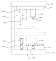
도 1은 본 발명의 일 실시예에 의한 프레스 금형 구조를 설명하기 위한 사시도1 is a perspective view for explaining a press mold structure according to an embodiment of the present invention
도 2a는 본 발명에 따른 하형 플레이트의 상부면에 다이고정판 및 커터다이가 차례로 적층 결합된 것을 나타낸 정면도Figure 2a is a front view showing that the die fixing plate and the cutter die are sequentially laminated to the upper surface of the lower die plate according to the present invention
도 2b는 본 발명에 따른 다이고정판을 나타낸 정면도 Figure 2b is a front view showing a die fixing plate according to the present invention
도 2c는 본 발명에 따른 커터다이를 나타낸 정면도Figure 2c is a front view showing a cutter die according to the present invention
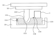
도 3은 본 발명의 일 실시예에 의한 프레스 금형 구조를 설명하기 위한 측면도Figure 3 is a side view for explaining the press mold structure according to an embodiment of the present invention
도 4는 도 3의 정면도4 is a front view of FIG. 3
도 5a 및 도 5b는 본 발명의 일 실시예에 따른 프레스 금형의 작동을 개략적으로 나타낸 도면5a and 5b schematically show the operation of the press mold according to an embodiment of the present invention;
도 6a는 본 발명의 다른 실시예에 따른 제 1 승강캠 펀치 및 제 1 캠 슬라이드의 개략적인 측면도6A is a schematic side view of a first lift cam punch and a first cam slide in accordance with another embodiment of the present invention;
도 6b는 도 6a의 작동도6B is an operational view of FIG. 6A
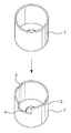
도 7은 종래의 솔레노이드 밸브용 케이스의 성형 전,후의 상태를 나타낸 사시도 7 is a perspective view showing a state before and after molding of a conventional case for a solenoid valve
*도면의 주요부분에 대한 부호의 설명** Description of the symbols for the main parts of the drawings *
1. 제품 10. 하형 플레이트1.
12. 다이고정판 14. 커터다이12. Die
20. 상형 플레이트 22. 승강캠 고정판20.
30. 취출수단 110. 제 1 캠 슬라이드30. Take-out means 110. First cam slide
112. 제 1 이동홈 114. 스프링112. First moving
115. 경사 슬립면 116. 커터고정블럭115. Inclined
118. 제 1 커터 120. 제 2 캠 슬라이드118. First Cutter 120. Second Cam Slide
122. 제 2 이동홈 124. 스프링122. Second moving
125. 경사 슬립면 126. 커터고정블럭125.
128. 제 2 커터 130. 제 3 캠 슬라이드128.
132. 제 3 이동홈 134. 스프링132. Third moving
135. 경사 슬립면 136. 커터고정블럭135.
138. 제 3 커터 140. 가이드 코어138. Third Cutter 140.Guide Core
150. 가이드포스트 152. 스프링150.Guestpost 152. Spring
210. 제 1 승강캠 펀치 212. 경사면210. First
220. 제 2 승강캠 펀치 222. 경사면220. 2nd
230. 가이드바 240. 누름부230.
310. 취출용 스프링 312. 안내구멍310. Spring for
본 발명은 솔레노이드 밸브용 케이스의 동시 노칭(NOTCHING) 가공을 위한 프레스 금형 구조에 관한 것으로, 더욱 상세하게는 상형 플레이트에 고정시킨 승강캠 펀치의 경사면에 의하여 하형 플레이트에 스프링으로 탄지되어 있는 3 개의 캠 슬라이드를 슬라이딩시켜 제품의 3 측면에 동시 노칭가공을 실시함으로써 동시가공에 따른 치수안정성이 우수한 솔레노이드 밸브용 케이스의 동시 노칭 가공을 위한 프레스 금형 구조에 관한 것이다.The present invention relates to a press mold structure for simultaneous notching processing of a solenoid valve case, and more particularly, three cams which are supported by a spring on a lower die plate by an inclined surface of an elevating cam punch fixed to an upper plate. The present invention relates to a press die structure for simultaneous notching processing of a case for a solenoid valve having excellent dimensional stability due to simultaneous processing by sliding a slide and performing simultaneous notching processing on three sides of the product.
일반적인 형태의 솔레노이드 밸브는 플런져 주위를 코일이 감싸고 있는 형태로서, 그러한 코일 외부에 원형 또는 사각형의 케이스(1)가 사용되고 있다.A solenoid valve of a general type is a form in which a coil is wrapped around a plunger, and a circular or
도 7을 참조하면, 상기 케이스(1)(이하 '제품'이라 칭한다)는 프레스 가공 공정을 이용하여 평판을 컵형상으로 딥드로우잉을 실시하고, 내경가공을 하기 위하여 CNC 선반 작업을 실시한 후 2 차공정으로 케이스의 하단에 3 방향으로 노칭 공정을 실시한다.Referring to FIG. 7, the case 1 (hereinafter referred to as 'product') is subjected to a deep drawing of a flat plate into a cup shape using a press working process, and then subjected to CNC lathe work for internal diameter machining. In the next step, the notching process is carried out in three directions at the bottom of the case.
이때 노칭 공정은 제품(1)을 본체 금형에 두고 3 방향의 슬라이드 형식의 커터가 작동되는데, 종래에는 3 개의 프레스에 각각의 커터다이(cutter die)를 둠으로써, 1차, 2차, 3차 프레스의 노칭 공정을 진행하기 위하여 별도의 프레스 3대가 필요하였고, 각 프레스마다 작업자가 제품(1)의 3 측면(2,3,4)을 가공하고 있는바, 기계사용료, 인건비, 생산시간 등 제조원가의 상승요인 등의 문제점이 있는 것이었다.At this time, the notching process puts the product (1) in the main mold and a three-way slide type cutter is operated. Conventionally, by placing each cutter die on three presses, primary, secondary, and tertiary In order to proceed with the notching process of the press, three separate presses were needed.In each press, the worker processes three sides (2, 3, 4) of the product (1). There were problems such as rising factors.
또한, 노칭가공시 다이(die)에서 제품(1)이 캠 슬라이드의 순간적인 가압에 유동되는 것을 방지하는 장치가 없어 제품(1)의 가공부위가 움직이게 되므로 제품(1)이 정밀하지 못하였고, 또한 가공부위가 거칠어 제품의 질을 저하시키는 등의 결함이 있었으며, 그리고 가공완료 후 제품(1)의 취출을 수동으로 한 것이어서 이에 따른 안전 사고 위험이 따랐을 뿐만 아니라 작업이 비능률적인 문제점이 있었다.In addition, there is no device that prevents the
따라서, 전술한 문제점을 해결하기 위하여 3 방향의 노칭 공정을 동시에 할 수 있는 캠 금형(cam die)이 요구되고 있었다.Accordingly, in order to solve the above problems, a cam die capable of simultaneously performing three-direction notching processes has been required.
따라서, 본 발명은 상기한 종래의 제반 문제점을 해결하기 위한 것으로, 솔레노이드 밸브용 케이스의 가공 공정에 있어서 3 방향의 노칭 공정으로 이동시키면서 노칭을 진행하던 종래의 공정을 단공정으로 3 방향 동시 노칭가공을 실시함으로써, 동시가공에 따른 치수안정성이 우수하여 제품의 품질을 균일하게 생산해 낼 수 있는 솔레노이드 밸브용 케이스의 동시 노칭 가공을 위한 프레스 금형 구조를 제공함을 기술적 과제로 삼는다.Accordingly, the present invention is to solve the above-mentioned general problems, the three-way simultaneous notching processing of the conventional process that proceeded the notching while moving to the three-direction notching process in the machining process of the solenoid valve case. The technical problem of the present invention is to provide a press mold structure for simultaneous notching processing of a solenoid valve case capable of uniformly producing product quality due to excellent dimensional stability due to simultaneous processing.
또한, 본 발명은 제품을 견고히 협지 고정시킨 후 가공시키게 되어 가공 부위의 변위를 방지하게 되므로 제품이 정밀하고도 미려하게 되는 효과가 있으며, 제품의 가공 후 스프링에 의하여 취출시키게 되므로 취출 작업을 기계적으로 시키므 로 종래 수공으로 취출시켜 사고의 위험이 따르고 작업이 비능률적인 결함을 제거하게 되어 작업에 능률을 높히고 양산을 기할 수 있는 솔레노이드 밸브용 케이스의 동시 노칭 가공을 위한 프레스 금형 구조를 제공함을 기술적 과제로 삼는다. In addition, the present invention has the effect that the product is precise and beautiful because it is processed after fixing the product firmly clamped to prevent the displacement of the processing site, and is taken out by the spring after the processing of the product mechanically take out operation The technical problem is to provide a press mold structure for simultaneous notching processing of a solenoid valve casing which can be removed by conventional handwork, which eliminates the risk of an accident and inefficient defects due to work. Do it.
상기한 목적의 달성을 위하여 본 발명에 따른 솔레노이드 밸브용 케이스의 동시 노칭 가공을 위한 프레스 금형 구조는, 제품의 측면에 노칭 가공하여 전단공을 형성하는 프레스 금형 구조에 있어서, 일측에 스프링을 개재하여 제 1,2,3 캠 슬라이드를 이동가능하게 수평 설치되는 제 1,2,3 이동홈이 형성된 다이고정판 및 상기 다이고정판의 상면에 결합되는 커터다이를 구비하는 하형 플레이트와; 상기 하형 플레이트의 대향하는 상부로 일정거리가 이격되게 유지되게 결합되는 승강캠 고정판의 하단면에 제 1 승강캠 펀치 및 제 2 승강캠 펀치가 구비되어 일체로 승강되는 상형 플레이트;를 포함하여 구성되어, 상기 상형 플레이트의 하강시 제 1 승강캠 펀치 및 제 2 승강캠 펀치의 경사면에 의하여 상기 제 1,2,3 캠 슬라이드를 일측으로 이동시켜 제품의 세 측면을 동시에 노칭가공하는 것을 특징으로 한다.Press mold structure for simultaneous notching processing of the solenoid valve case according to the present invention for achieving the above object, in the press mold structure to form a shear hole by notching on the side of the product, via a spring on one side A lower die plate including a die fixing plate having first and second moving grooves horizontally installed to move the first and second cam slides, and a cutter die coupled to an upper surface of the die fixing plate; A first lifting cam punch and a second lifting cam punch are provided on the bottom surface of the lifting cam fixing plate which is coupled to maintain a predetermined distance apart from the upper portion of the lower die plate, and the upper lifting plate is lifted integrally. When the upper plate is lowered, the first, second and third cam slides are moved to one side by the inclined surfaces of the first and second lifting cam punches, and the three side surfaces of the product are notched.
또한, 본 발명에 있어서 상기 커터다이는, 중앙부에 제품을 정확히 삽입시킬 수 있도록 가이드 코어(guide core)가 관통 형성된 것을 특징으로 한다.In the present invention, the cutter die is characterized in that the guide core is formed so as to penetrate the product accurately in the center portion.
또한, 본 발명에 있어서 상기 제 1 캠 슬라이드는, 상기 제 1 이동홈에서 전후로 활주 이동가능하도록 끼워지며, 외곽 상부 모서리가 외측으로 경사진 경사 슬립면을 가지며, 제 1 커터가 부착된 커터고정블록에 의해 제품의 일측면 하단을 컷팅 가공하도록 설치되는 것을 특징으로 한다.In addition, in the present invention, the first cam slide is fitted so as to slide back and forth in the first moving groove, the outer edge has an inclined slip surface inclined outward, the cutter fixing block with a first cutter It characterized in that it is installed to cut the bottom of one side of the product.
또한, 본 발명에 있어서 상기 제 2,3 캠 슬라이드는, 상기 제 2,3 이동홈에서 좌우로 활주 이동가능하도록 끼워지며, 외곽 상부 모서리가 내측으로 경사진 경사 슬립면을 가지며, 커터가 부착된 커터고정블록에 의해 제품의 좌,우측면 하단을 컷팅 가공하도록 설치되는 것을 특징으로 한다.In addition, in the present invention, the second and third cam slides are fitted to be slidable from side to side in the second and third moving grooves, and have an inclined slip surface having an outer upper edge inclined inwardly, and having a cutter attached thereto. It is characterized in that the cutter is installed to cut the lower left and right side of the product by the fixing block.
또한, 본 발명에 있어서 상기 제 1 승강캠 펀치는, 하단부 일측 모서리에 상기 제 1 캠 슬라이드의 경사 슬립면과 대응하는 경사면이 형성되어 하강시 제 1 캠 슬라이드를 일측으로 슬라이딩시키는 것을 특징으로 한다.In the present invention, the first lifting cam punch is characterized in that the inclined surface corresponding to the inclined slip surface of the first cam slide is formed at one side edge of the lower end to slide the first cam slide to one side when lowering.
또한, 본 발명에 있어서, 상기 제 2 승강캠 펀치는, 상기 승강캠 고정판의 하단면에 결합되며, 하단부 양측 모서리에 상기 제 2,3 캠 슬라이드의 경사 슬립면과 대응하는 경사면이 형성되어 하강시 제 2,3 캠 슬라이드를 양측으로 슬라이딩시키는 것을 특징으로 한다.In addition, in the present invention, the second lifting cam punch is coupled to the bottom surface of the lifting cam fixing plate, and the inclined surface corresponding to the inclined slip surface of the second and third cam slides is formed at both bottom edges of the lower portion and is lowered. And sliding the second and third cam slides to both sides.
또한, 본 발명에 있어서, 상기 하형 플레이트에 안내구멍을 형성하고, 각 구멍에 취출용 스프링을 장설하여 상기 커터다이의 상단에 안착된 제품을 노칭가공 후 취출시키는 취출수단;을 더 구비한 것을 특징으로 한다.In the present invention, the lower die plate is formed with a guide hole, each take-out spring is installed in each of the take-out means for taking out the product seated on the upper end of the cutter die after notching processing; It is done.
이하에서 본 발명의 실시예를 도시한 첨부도면을 참조하여 본 발명을 상세히 설명한다.Hereinafter, with reference to the accompanying drawings showing an embodiment of the present invention will be described in detail the present invention.
도 1은 본 발명의 일 실시예에 의한 프레스 금형 구조를 설명하기 위한 사시도이고, 도 2a는 본 발명에 따른 하형 플레이트의 상부면에 다이고정판 및 커터다이가 차례로 적층 결합된 것을 나타낸 정면도이고, 도 2b는 본 발명에 따른 다이고 정판을 나타낸 정면도이고, 도 2c는 본 발명에 따른 커터다이를 나타낸 정면도이고, 도 3은 본 발명의 일 실시예에 의한 프레스 금형 구조를 설명하기 위한 측면도이고, 도 4는 도 3의 정면도이고, 도 5a 및 도 5b는 본 발명의 일 실시예에 따른 프레스 금형의 작동을 개략적으로 나타낸 도면이고, 도 6은 본 발명의 다른 실시예에 따른 제 1 승강캠 펀치 및 제 1 캠 슬라이드의 측면도를 각각 나타낸 것이다. Figure 1 is a perspective view for explaining the press mold structure according to an embodiment of the present invention, Figure 2a is a front view showing that the die fixing plate and the cutter die are sequentially laminated to the upper surface of the lower die plate according to the present invention, Figure 2b is a front view showing a die plate according to the present invention, Figure 2c is a front view showing a cutter die according to the present invention, Figure 3 is a side view for explaining the press mold structure according to an embodiment of the present invention, Figure 4 is a front view of Figure 3, Figures 5a and 5b is a view schematically showing the operation of the press die according to an embodiment of the present invention, Figure 6 is a first lifting cam punch and according to another embodiment of the present invention The side view of the 1st cam slide is shown, respectively.
도 1은 본 발명의 일 실시예에 의한 프레스 금형 구조를 설명하기 위한 사시도로서, 도 1을 참조하면, 본 발명의 일 실시예에 의한 프레스 금형 구조는 하형 플레이트(10)의 상부면에 다이고정판(12) 및 커터다이(14)가 차례로 적층 결합되고, 그 하형 플레이트(10)의 대향하는 상부로 일정거리 이격되게 유지됨과 동시에 상하로 승하강되는 상형 플레이트(20)가 형성되며, 그 상형 플레이트(20)의 하부면에는 다수 개의 승강캠 펀치(210,220)과 가이드바(230)가 고정되게 장착된 승강캠 고정판(22)이 고정되게 형성된다.1 is a perspective view illustrating a press mold structure according to an embodiment of the present invention. Referring to FIG. 1, a press mold structure according to an embodiment of the present invention is a die fixing plate on an upper surface of a
먼저, 도 2a 및 2c에 도시된 바와 같이, 본 발명에 프레스 금형 구조는 바닥에 설치되는 상기 하형 플레이트(10)의 상부면에 다이고정판(12) 및 커터다이(14)가 적층되어 결합된다.First, as shown in Figures 2a and 2c, the press mold structure in the present invention is coupled to the
도 2a 및 도 2b를 참조하면, 상기 다이고정판(12)은 각각 3 개의 캠 슬라이드(110,120,130)와 상기 캠 슬라이드의 이동홈(112,122,132) 및 스프링(114,124,134)을 갖는다.2A and 2B, the
즉, 상기 다이고정판(12)은 세 개의 제1,2,3 이동홈(112,122,132)이 마련되고, 이들 각 이동홈(112,122,132)의 단부에는 제 1 캠 슬라이드(110) 및 제 2,3 캠 슬라이드(120,130)가 결합되는데, 각각의 캠 슬라이드(110,120,130)의 일측에는 스프링(114,124,134)을 개재하여 이동홈(112,122,132) 내에서 상기 캠 슬라이드(110,120,130)가 탄력적으로 이동가능하게 설치된다.That is, the
즉, 제 1 캠 슬라이드(110)의 일측에 스프링(114)을 개재하여 제 1 이동홈(112) 내에서 상기 제 1 캠 슬라이드(110)가 탄력적으로 전후 이동가능하도록 설치된다.That is, the
또한, 제 2 캠 슬라이드(120)의 일측에 스프링(124)을 개재하여 제 2 이동홈(122) 내에서 상기 제 2 캠 슬라이드(120)가 탄력적으로 좌우 이동가능하도록 설치된다.In addition, the
또한, 제 3 캠 슬라이드(130)의 일측에 스프링(134)을 개재하여 제 3 이동홈(132) 내에서 상기 제 3 캠 슬라이드(130)가 탄력적으로 좌우 이동가능하도록 설치된다.In addition, the
상기 제 1 캠 슬라이드(110)의 상단 일측 모서리에는 경사 슬립면(115)이 형성되어 아래에서 설명될 제 1 승강캠 펀치(210)의 경사면(212)과 슬라이딩 접촉하면서 상기 제 1 캠 슬라이드(110)를 내측으로 슬라이딩하게 된다.An
또한, 상기 제 2 캠 슬라이드(120) 및 제 3 캠 슬라이드(130)의 상단 일측 모서리에도 경사 슬립면(125,135)이 형성되어 아래에서 설명될 제 2 승강캠 펀치(220)의 경사면(222)과 슬라이딩 접촉하면서 상기 제 2 캠 슬라이더(120)를 양측으로 밀어내게 된다.In addition, the inclined slip surfaces 125 and 135 are also formed at one corners of the upper ends of the
또한, 상기 캠 슬라이드(110,120,130)는 각각의 경사 슬립면(115,125,135)이 형성된 위치의 후방 상면에 커터(118,128,138)가 구비된 커터고정블럭(116,126,136)이 볼트(미도시)로 결합되어 장착된다.In addition, the cam slides 110, 120, and 130 are mounted with the
도 2c를 참조하면, 상기 커터다이(14)는 상기 다이고정판(12)의 중앙 상면에 설치되는 것으로서, 중앙부에 가이드 코어(140)(guide core)가 관통 형성되어 있어 제품을 금형 내부에 정확히 삽입시킬 수 있게 된다.Referring to FIG. 2C, the cutter die 14 is installed on the upper surface of the center of the
도 3는 본 발명의 일 실시예에 의한 프레스 금형 구조를 설명하기 위한 측면도이고, 도 4는 도 3의 정면도를 각각 나타낸 것으로, 도 3 및 도 4를 참조하면 상기 상형 플레이트(20)는 유압실린더(미도시)에 의해 상하로 이동된다.Figure 3 is a side view for explaining the press mold structure according to an embodiment of the present invention, Figure 4 is a front view of Figure 3, respectively, referring to Figures 3 and 4 the
즉, 상기 유압실린더는 상기 상형 플레이트(20)의 상측에 위치되어 유압의 작용력으로 상기 상형 플레이트(20)를 상하로 이동시키는 것으로, 실린더 보디의 내부에서 인출되는 로드의 선단에는 상형 플레이트(20)가 장착되어 있어, 상기 유압실린더 측으로 유압이 가해져서 로드가 실린더 보디의 내부로부터 승,하강하게 되면 상기 상형 플레이트(20)가 상하로 움직이게 된다.That is, the hydraulic cylinder is located on the upper side of the
또한, 상기 상형 플레이트(20)의 하측면에는 상기 제 1 승강캠 펀치(210)와 제 2 승강캠 펀치(220)가 부착된 승강캠 고정판(22) 및 가이드바(230)가 결합된다. In addition, the lifting
상기 승강캠 고정판(22)은 상기 상형 플레이트(20)와 함께 승강되는 것으로서, 하측으로 일정길이 연장된 제 1 승강캠 펀치(210) 및 제 2 승강캠 펀치(220)가 고정 설치된다.The elevating
상기 제 1 승강캠 펀치(210)는 상기 승강캠 고정판(22)에서 상형 플레이트 (20)와 함께 승, 하강하면서 상기 하형 플레이트(10)의 다이고정판(12)에 장착된 제1 캠 슬라이드(110)를 내측으로 슬라이딩시킨다.The first
즉, 상기 제 1 승강캠 펀치(210)는 하단부 일측 모서리에 상기 제 1 캠 슬라이드(110)의 경사 슬립면(115)과 대응하는 경사면(212)이 형성되어 하강시 제 1 캠 슬라이드(110)를 일측으로 슬라이딩시키는 역할을 담당한다.That is, the first
상기 제 2 승강캠 펀치(220)는 상기 제 1 승강캠 펀치(210)와 이격되어 승강캠 고정판(22)에 부착되는 것으로서, 상기 승강캠 고정판(22)과 함께 승강되면서 커터다이(14)의 가이드 코어(140)로 인입하여 상기 제 2,3 캠 슬라이드(120,130)의 경사 슬립면(125,135)을 타고 밀고 들어가 제 2,3 캠 슬라이드(120,130)를 양측으로 슬라이딩시킨다.The second
이때, 상기 제 2 승강캠 펀치(220)의 선단부는 커터다이(14)의 가이드 코어(140)로 삽입되기 위하여 상기 가이드 코어(140)의 내경보다는 적은 크기의 직경을 갖추면서 삽입이 용이하게 이루어지도록 양측 모서리 부분이 테이퍼가공되어 있는 경사면(222)을 갖는다.At this time, the front end of the second
또한, 상기 제 2 승강캠(220)의 직경은 가이드 코어(140)의 내경으로 삽입됨으로써 상기 제 2,3 캠 슬라이드(120,130)의 슬라이딩되는 좌, 우 이동거리가 제한되도록 구성되는 것이다.In addition, the diameter of the second elevating
한편, 상기 상형 플레이트(20)는 하형 플레이트(10)를 향하여 제 1,2 승강캠 펀치(210,220)가 원활히 하강하면서 제1,2,3 캠 슬라이드(110,120,130)를 슬라이딩시킬 수 있도록 가이드 역할을 하는 가이드바(230)가 더 구비되고, 상기 하부 플레 이트의 상단 양측에는 일정한 높이의 가이드포스트(150)가 구비되는 것이 바람직하다.Meanwhile, the
상기 가이드바(230) 및 가이드포스트(150)는 통상의 슬라이딩 수단을 매개로 결합되는데, 상기 슬라이딩수단은 가이드포스트(150)를 따라 설치되는 스프링(152)으로 이루어진다.The
따라서, 상기 가이드포스트(150)가 가이드바(230)를 수용하여 상기 상형 플레이트(20)의 상,하 이동거리를 제한할 수 있게 되는 것이다.Therefore, the
한편, 상기 상형 플레이트(20)는 하강시 상기 커터다이(14)의 상단에 안착된 제품(1)을 눌러 고정시킬 수 있도록 누름부(240)가 더 설치되는 것이 바람직하다. On the other hand, the
즉, 상기 누름부(240)는 제품(1)을 눌러 상측으로 돌출되는 것을 피할 수 있도록 지지해 주어 정확한 노칭 공정이 동시에 3방향 노칭이 가능하도록 하는 구성요소의 역할을 한다.That is, the
따라서, 제품은 가이드 코어(140) 및 누름부(240)에 의해 커터다이(14)에 견고히 장착되고, 상기와 같은 노칭 작업이 완료되면, 상기 상형 플레이트(20)는 상승함으로써 제 1, 2 승강캠 펀치(210,220)와 가이드바(230)는 최초의 위치로 복귀되어 다음 작업에 대비하는 것이다.Therefore, the product is firmly mounted to the cutter die 14 by the
한편, 본 발명의 바람직한 다른 실시예에 있어서 상기 커터다이(14)의 상단에 안착된 제품(1)을 노칭가공 후 취출시킬 수 있도록 취출수단(30)이 구비된다.On the other hand, in another preferred embodiment of the present invention is provided with a take-out means 30 to take out the
상기 취출수단(30)은 상기 제 1 캠 슬라이드(110)에 취출용 스프링(310)을 장설하여 제품(1)을 축출되게 한다.The take-out means 30 installs a take-out
이를 위해 상기 제 1 캠 슬라이드(110)는 취출용 스프링(310)의 수에 해당하는 만큼의 안내구멍(312)을 가지고 있다.To this end, the
상기 안내구멍(312)의 내부에 취출용 스프링(310)이 내장되어 있어 상기 제 1 캠 슬라이드(110)가 내측으로 이동되더라도 취출용 스프링(310)과 충돌되지 않게 된다. The take-out
따라서, 노칭가공이 완료되면, 상기 취출용 스프링(310)의 탄성에 의해 커터다이(14) 상단에 안착된 제품(1)을 취출시키게 된다.Therefore, when the notching processing is completed, the
이와 같은 구성원리로 된 본 발명에 따른 장치의 작용을 설명하면 다음과 같다.Referring to the operation of the device according to the present invention as a member as follows.
먼저 제품(1)을 노칭 가공하기 위해서는 철판을 가공 등을 통해 평판을 컵(cup) 형상으로 딥드로우잉을 실시하는 공정이 선행되어야 한다.First, in order to notch the
이후, 상기 하형 플레이트(10)에 안착된 커터다이(14)의 가이드 코어(140)에 제품(1)이 인입된 상태에서 수직 작동용 유압실린더(미도시)를 작동시키게 되면 피스톤이 출현작동하게 됨으로써 이에 따라 상기 상형 플레이트(20)가 하강하기 시작하고, 상기 상형 플레이트(20)의 하단 양측에 형성된 가이드바(230)가 하형 플레이트(10)의 가이드포스트(150)를 타고 슬라이딩하게 됨으로써 상형 플레이트(20)는 흔들림 현상 없이 원하는 위치로 하강하게 된다.Subsequently, when the hydraulic cylinder for vertical operation (not shown) is operated in the state in which the
이때 상기 누름부(240)가 상기 제품(1)을 누르면서 커터다이(14)의 가이드 코어(140) 내에 고정시키게 된다.At this time, the
도 5a 및 도 5b를 참조하면, 상기 상형 플레이트(20)의 계속되는 하강으로 상기 제 1 승강캠 펀치(210)가 하강하게 되고, 상기 제 1 승강캠 펀치(210)의 경사면이 상기 제 1 캠 슬라이드(110)의 경사 슬립면(115)과 슬라이딩 접촉하면서 제 1 캠 슬라이드(110)를 내측 방향으로 전진시키게 되어 제 1 캠 슬라이드(110)의 일측에 설치된 커터고정블럭(116)의 제 1 커터(118)가 제품(1)의 일측을 컷팅 가공함과 동시 절단하게 된다.5A and 5B, the first
이와 동시에, 상기 제 2 승강캠 펀치(220)가 하강하게 되고, 상기 제2 승강캠 펀치(220)의 경사면이 상기 제 2,3 캠 슬라이드(120,130)의 경사 슬립면(125,135)과 슬라이딩 접촉하면서 제 2,3 캠 슬라이드(120,130)를 외측 방향으로 이동시키게 되어 제 2,3 캠 슬라이드(120,130)의 내측에 설치된 커터고정블럭(126,136)의 제 2 커터(128) 및 제 3 커터(138)가 제품(1)의 양측을 컷팅 가공함과 동시 절단하게 된다.At the same time, the second
이와 같이 상기 제 1,2 승강캠 펀치(210,220)에 의한 제 1,2,3 캠 슬라이드(110,120,130)의 동시이동으로 3 방향 노칭가공을 실시함으로써, 동시가공에 따른 치수안정성이 우수하여 제품의 품질을 균일하게 생산해 낼 수 있게 되는 것이다.Thus, by performing the three-way notching processing by the simultaneous movement of the first, second and third cam slides (110, 120, 130) by the first and second lifting cam punches (210, 220), it is excellent in dimensional stability due to the simultaneous processing, the product quality It will be able to produce uniformly.
이후, 상형 플레이트(20)가 상승하면서 상기 제 1,2 승강캠 펀치(210,220)도 함께 상승하게 되는데, 이때 상기 제 1,2,3 캠 슬라이드(110,120,130)에 의해 밀려난 스프링(114,124,134)의 복원력에 의해 다시 제자리로 위치하여 정지한다.Thereafter, as the
한편, 상기 상형 플레이트(20)의 상승시 상기 제품(1)을 고정하는 누름부 (240)도 함께 상승하면서 제품에 대한 고정이 해제되고, 이와 동시에 상기 하형 플레이트(10)에 구비된 취출용 스프링(310)에 의해 상기 커터다이(14) 상단에 안착되어 있는 노칭가공이 완료된 제품(1)이 커터다이(14)로부터 취출된다. On the other hand, when the
도 6은 본 발명의 다른 실시예에 따른 제 1 승강캠 펀치 및 제 1 캠 슬라이드의 개략적인 측면도로서, 도 6을 참조하면, 본 발명의 바람직한 다른 실시예에 있어서는 상기 제 1 승강캠 펀치(210)가 제 1 캠 슬라이드(110)를 외측으로 이동시킬 수 있도록 구성될 수도 있다.FIG. 6 is a schematic side view of a first lifting cam punch and a first cam slide according to another embodiment of the present invention. Referring to FIG. 6, in another preferred embodiment of the present invention, the first
즉, 상기 제 1 승강캠 펀치(210)의 경사면(212) 및 제 1 캠 슬라이드(110)의 경사 슬립면(115)이 도 1에 도시된 것과는 반대로 형성되며, 스프링(114)도 반대측 위치에 형성된다.That is, the
따라서, 제 1 승강캠 펀치(210)의 형상에 따라 내측에서의 외측으로, 외측에서 내측으로 어떠한 방향이든 동시 가공이 가능한 구조와 기능을 갖는다.Therefore, according to the shape of the first
이상에서 설명한 바와 같이, 본 발명의 솔레노이드 밸브용 케이스의 동시 노칭 가공을 위한 프레스 금형 구조는 케이스 가공시 3 공정으로 이동시키면서 노칭을 진행하던 종래 공정을 단공정의 3방향 동시가공으로 실시함으로써, 동시가공에 따른 치수안정성이 우수하여 제품의 품질을 균일하게 생산해 낼 수 있는 효과를 제공한다.As described above, the press mold structure for the simultaneous notching processing of the case for the solenoid valve of the present invention is carried out by performing the conventional process of notching while moving to three processes in case processing, Excellent dimensional stability due to processing provides the effect of producing uniform product quality.
또한, 본 발명은 제품을 견고히 협지 고정시킨 후 가공시키게 되어 가공 부 위의 변위를 방지하게 되므로 제품이 정밀하고도 미려하게 되는 효과가 있으며, 제품의 가공 후 스프링에 의하여 취출시키게 되므로 취출 작업을 기계적으로 시키므로 종래 수공으로 취출시켜 사고의 위험이 따르고 작업이 비능률적인 결함을 제거하게 되어 작업에 능률을 높이고 양산을 기할 수 있는 효과를 제공한다. In addition, the present invention has the effect that the product is precise and beautiful because it is processed after fixing the product firmly clamped to prevent the displacement of the processing part, and the take-out operation is mechanically taken out by the spring after processing the product. Since it is taken out by the conventional hand, the risk of accidents and the inefficient defects of the work is eliminated, thereby increasing the efficiency and mass production of the work.
지금까지는 본 발명의 특정한 실시예를 중심으로 설명하였으나, 본 발명의 청구범위에 기재된 기술사상을 벗어나지 않는 범위 내에서 상술한 바와 같이 다양한 수정 및 변경이 이루어질 수 있음이 명백하다. 따라서, 본 발명의 상세한 설명 및 첨부된 도면은 본 발명의 기술 사상을 한정하는 것이 아니라 예시한 것으로 해석되어야 한다.The present invention has been described with reference to specific embodiments of the present invention, but it is apparent that various modifications and changes can be made as described above without departing from the technical spirit described in the claims of the present invention. Accordingly, the detailed description of the invention and the accompanying drawings should be construed as illustrative rather than limiting to the spirit of the invention.
Claims (5)
Priority Applications (1)
| Application Number | Priority Date | Filing Date | Title |
|---|---|---|---|
| KR1020050095208A KR100552631B1 (en) | 2005-10-11 | 2005-10-11 | Press mold construction for simultaneous notching of solenoid valve cases |
Applications Claiming Priority (1)
| Application Number | Priority Date | Filing Date | Title |
|---|---|---|---|
| KR1020050095208A KR100552631B1 (en) | 2005-10-11 | 2005-10-11 | Press mold construction for simultaneous notching of solenoid valve cases |
Publications (1)
| Publication Number | Publication Date |
|---|---|
| KR100552631B1 true KR100552631B1 (en) | 2006-02-21 |
Family
ID=37178914
Family Applications (1)
| Application Number | Title | Priority Date | Filing Date |
|---|---|---|---|
| KR1020050095208A Expired - Fee Related KR100552631B1 (en) | 2005-10-11 | 2005-10-11 | Press mold construction for simultaneous notching of solenoid valve cases |
Country Status (1)
| Country | Link |
|---|---|
| KR (1) | KR100552631B1 (en) |
Cited By (6)
| Publication number | Priority date | Publication date | Assignee | Title |
|---|---|---|---|---|
| KR101270163B1 (en) | 2012-11-16 | 2013-05-31 | 서철상 | The safety tab manufacture device and manufacture method |
| KR101483108B1 (en) * | 2013-07-17 | 2015-01-15 | 전북대학교산학협력단 | Pressing device |
| CN110340206A (en) * | 2019-07-24 | 2019-10-18 | 长春事达汽车零部件有限公司 | sheet metal cutting die |
| CN111604408A (en) * | 2020-06-18 | 2020-09-01 | 重庆爱驰威汽车零部件有限公司 | A four-sided side trimming die for truck inner and outer cone protruding |
| CN113399541A (en) * | 2021-07-21 | 2021-09-17 | 宁波继峰科技有限公司 | Side punching groove device for workpiece |
| KR102330352B1 (en) * | 2021-05-07 | 2021-11-23 | 디에스 (주) | Cutting device and set of parts for the same |
-
2005
- 2005-10-11 KR KR1020050095208A patent/KR100552631B1/en not_active Expired - Fee Related
Cited By (7)
| Publication number | Priority date | Publication date | Assignee | Title |
|---|---|---|---|---|
| KR101270163B1 (en) | 2012-11-16 | 2013-05-31 | 서철상 | The safety tab manufacture device and manufacture method |
| KR101483108B1 (en) * | 2013-07-17 | 2015-01-15 | 전북대학교산학협력단 | Pressing device |
| CN110340206A (en) * | 2019-07-24 | 2019-10-18 | 长春事达汽车零部件有限公司 | sheet metal cutting die |
| CN110340206B (en) * | 2019-07-24 | 2024-06-04 | 长春事达汽车零部件有限公司 | Metal plate shearing die |
| CN111604408A (en) * | 2020-06-18 | 2020-09-01 | 重庆爱驰威汽车零部件有限公司 | A four-sided side trimming die for truck inner and outer cone protruding |
| KR102330352B1 (en) * | 2021-05-07 | 2021-11-23 | 디에스 (주) | Cutting device and set of parts for the same |
| CN113399541A (en) * | 2021-07-21 | 2021-09-17 | 宁波继峰科技有限公司 | Side punching groove device for workpiece |
Similar Documents
| Publication | Publication Date | Title |
|---|---|---|
| KR20100006470A (en) | Compositive press molding apparatus | |
| CN105382068B (en) | The device and method of the cut surface with burr on finishing stamping parts or fine part | |
| CN116532562B (en) | Automatic stamping equipment of switch board panel | |
| KR100552631B1 (en) | Press mold construction for simultaneous notching of solenoid valve cases | |
| JPS61238426A (en) | Press with guiding and detaching device for metallic band plate | |
| US5361619A (en) | Process and apparatus for press forming | |
| EP3247541B1 (en) | Wallboard punch assembly with stripper bushings | |
| CN106182166B (en) | Decorative strip punching equipment | |
| CN210497897U (en) | Tubular section bar piercing press | |
| EP2254711B1 (en) | Process and apparatus for positioning laminations | |
| KR100436006B1 (en) | Tool equipment form possible press one stroke | |
| CN214488489U (en) | Pipe fitting lateral wall notching die | |
| KR100626210B1 (en) | Draw Molding Equipment | |
| CN111589927B (en) | Punch forming system of static iron core of starter | |
| CN113145732A (en) | Pipe fitting lateral wall notching die | |
| JPS63123538A (en) | Intermediate tool ejection device in mold equipment | |
| JP4388010B2 (en) | Drawing process manufacturing method and drawing process manufacturing equipment by progressive processing | |
| JP3946564B2 (en) | Method of start-up / punch-down by punch press and punch mold and die mold used for the method | |
| CN220611998U (en) | Hardware stamping side punching die | |
| CN222113242U (en) | Barb type inclined wedge punching machine | |
| KR200337217Y1 (en) | Complex press apparatus for punching a building pannel | |
| CN204620838U (en) | The progressive die of installation foot before making automotive seat | |
| CN217748924U (en) | Split type fashioned five metals precision mould | |
| CN216729257U (en) | Automobile part mistake proofing forming device | |
| JP3491640B2 (en) | Manufacturing method of laminated product of different shape by sheet metal press punching, and press device for rib forming |
Legal Events
| Date | Code | Title | Description |
|---|---|---|---|
| A201 | Request for examination | ||
| PA0109 | Patent application |
St.27 status event code: A-0-1-A10-A12-nap-PA0109 |
|
| PA0201 | Request for examination |
St.27 status event code: A-1-2-D10-D11-exm-PA0201 |
|
| A302 | Request for accelerated examination | ||
| PA0302 | Request for accelerated examination |
St.27 status event code: A-1-2-D10-D17-exm-PA0302 St.27 status event code: A-1-2-D10-D16-exm-PA0302 |
|
| E701 | Decision to grant or registration of patent right | ||
| PE0701 | Decision of registration |
St.27 status event code: A-1-2-D10-D22-exm-PE0701 |
|
| GRNT | Written decision to grant | ||
| PR0701 | Registration of establishment |
St.27 status event code: A-2-4-F10-F11-exm-PR0701 |
|
| PR1002 | Payment of registration fee |
St.27 status event code: A-2-2-U10-U11-oth-PR1002 Fee payment year number: 1 |
|
| PG1601 | Publication of registration |
St.27 status event code: A-4-4-Q10-Q13-nap-PG1601 |
|
| PR1001 | Payment of annual fee |
St.27 status event code: A-4-4-U10-U11-oth-PR1001 Fee payment year number: 4 |
|
| PR1001 | Payment of annual fee |
St.27 status event code: A-4-4-U10-U11-oth-PR1001 Fee payment year number: 5 |
|
| LAPS | Lapse due to unpaid annual fee | ||
| PC1903 | Unpaid annual fee |
St.27 status event code: A-4-4-U10-U13-oth-PC1903 Not in force date: 20110210 Payment event data comment text: Termination Category : DEFAULT_OF_REGISTRATION_FEE |
|
| K11-X000 | Ip right revival requested |
St.27 status event code: A-6-4-K10-K11-oth-X000 |
|
| PC1903 | Unpaid annual fee |
St.27 status event code: N-4-6-H10-H13-oth-PC1903 Ip right cessation event data comment text: Termination Category : DEFAULT_OF_REGISTRATION_FEE Not in force date: 20110210 |
|
| PR0401 | Registration of restoration |
St.27 status event code: A-6-4-K10-K13-oth-PR0401 |
|
| R401 | Registration of restoration | ||
| PR1001 | Payment of annual fee |
St.27 status event code: A-4-4-U10-U11-oth-PR1001 Fee payment year number: 6 |
|
| R18-X000 | Changes to party contact information recorded |
St.27 status event code: A-5-5-R10-R18-oth-X000 |
|
| PR1001 | Payment of annual fee |
St.27 status event code: A-4-4-U10-U11-oth-PR1001 Fee payment year number: 7 |
|
| FPAY | Annual fee payment |
Payment date: 20130131 Year of fee payment: 8 |
|
| PR1001 | Payment of annual fee |
St.27 status event code: A-4-4-U10-U11-oth-PR1001 Fee payment year number: 8 |
|
| FPAY | Annual fee payment |
Payment date: 20140203 Year of fee payment: 9 |
|
| PR1001 | Payment of annual fee |
St.27 status event code: A-4-4-U10-U11-oth-PR1001 Fee payment year number: 9 |
|
| FPAY | Annual fee payment |
Payment date: 20150202 Year of fee payment: 10 |
|
| PR1001 | Payment of annual fee |
St.27 status event code: A-4-4-U10-U11-oth-PR1001 Fee payment year number: 10 |
|
| FPAY | Annual fee payment |
Payment date: 20160203 Year of fee payment: 11 |
|
| PR1001 | Payment of annual fee |
St.27 status event code: A-4-4-U10-U11-oth-PR1001 Fee payment year number: 11 |
|
| P22-X000 | Classification modified |
St.27 status event code: A-4-4-P10-P22-nap-X000 |
|
| FPAY | Annual fee payment |
Payment date: 20170209 Year of fee payment: 12 |
|
| PR1001 | Payment of annual fee |
St.27 status event code: A-4-4-U10-U11-oth-PR1001 Fee payment year number: 12 |
|
| FPAY | Annual fee payment |
Payment date: 20180207 Year of fee payment: 13 |
|
| PR1001 | Payment of annual fee |
St.27 status event code: A-4-4-U10-U11-oth-PR1001 Fee payment year number: 13 |
|
| FPAY | Annual fee payment |
Payment date: 20190207 Year of fee payment: 14 |
|
| PR1001 | Payment of annual fee |
St.27 status event code: A-4-4-U10-U11-oth-PR1001 Fee payment year number: 14 |
|
| FPAY | Annual fee payment |
Payment date: 20200210 Year of fee payment: 15 |
|
| PR1001 | Payment of annual fee |
St.27 status event code: A-4-4-U10-U11-oth-PR1001 Fee payment year number: 15 |
|
| PR1001 | Payment of annual fee |
St.27 status event code: A-4-4-U10-U11-oth-PR1001 Fee payment year number: 16 |
|
| PR1001 | Payment of annual fee |
St.27 status event code: A-4-4-U10-U11-oth-PR1001 Fee payment year number: 17 |
|
| PR1001 | Payment of annual fee |
St.27 status event code: A-4-4-U10-U11-oth-PR1001 Fee payment year number: 18 |
|
| PR1001 | Payment of annual fee |
St.27 status event code: A-4-4-U10-U11-oth-PR1001 Fee payment year number: 19 |
|
| PC1903 | Unpaid annual fee |
St.27 status event code: A-4-4-U10-U13-oth-PC1903 Not in force date: 20250210 Payment event data comment text: Termination Category : DEFAULT_OF_REGISTRATION_FEE |
|
| H13 | Ip right lapsed |
Free format text: ST27 STATUS EVENT CODE: N-4-6-H10-H13-OTH-PC1903 (AS PROVIDED BY THE NATIONAL OFFICE); TERMINATION CATEGORY : DEFAULT_OF_REGISTRATION_FEE Effective date: 20250210 |
|
| PC1903 | Unpaid annual fee |
St.27 status event code: N-4-6-H10-H13-oth-PC1903 Ip right cessation event data comment text: Termination Category : DEFAULT_OF_REGISTRATION_FEE Not in force date: 20250210 |