KR100504082B1 - Manual Pump Sprayer - Google Patents
Manual Pump Sprayer Download PDFInfo
- Publication number
- KR100504082B1 KR100504082B1 KR1019970002383A KR19970002383A KR100504082B1 KR 100504082 B1 KR100504082 B1 KR 100504082B1 KR 1019970002383 A KR1019970002383 A KR 1019970002383A KR 19970002383 A KR19970002383 A KR 19970002383A KR 100504082 B1 KR100504082 B1 KR 100504082B1
- Authority
- KR
- South Korea
- Prior art keywords
- chamber
- spin
- fluid
- probe
- damping chamber
- Prior art date
- Legal status (The legal status is an assumption and is not a legal conclusion. Google has not performed a legal analysis and makes no representation as to the accuracy of the status listed.)
- Expired - Fee Related
Links
Images


Classifications
-
- B—PERFORMING OPERATIONS; TRANSPORTING
- B05—SPRAYING OR ATOMISING IN GENERAL; APPLYING FLUENT MATERIALS TO SURFACES, IN GENERAL
- B05B—SPRAYING APPARATUS; ATOMISING APPARATUS; NOZZLES
- B05B1/00—Nozzles, spray heads or other outlets, with or without auxiliary devices such as valves, heating means
- B05B1/34—Nozzles, spray heads or other outlets, with or without auxiliary devices such as valves, heating means designed to influence the nature of flow of the liquid or other fluent material, e.g. to produce swirl
- B05B1/3405—Nozzles, spray heads or other outlets, with or without auxiliary devices such as valves, heating means designed to influence the nature of flow of the liquid or other fluent material, e.g. to produce swirl to produce swirl
- B05B1/341—Nozzles, spray heads or other outlets, with or without auxiliary devices such as valves, heating means designed to influence the nature of flow of the liquid or other fluent material, e.g. to produce swirl to produce swirl before discharging the liquid or other fluent material, e.g. in a swirl chamber upstream the spray outlet
- B05B1/3478—Nozzles, spray heads or other outlets, with or without auxiliary devices such as valves, heating means designed to influence the nature of flow of the liquid or other fluent material, e.g. to produce swirl to produce swirl before discharging the liquid or other fluent material, e.g. in a swirl chamber upstream the spray outlet the liquid flowing at least two different courses before reaching the swirl chamber
-
- B—PERFORMING OPERATIONS; TRANSPORTING
- B05—SPRAYING OR ATOMISING IN GENERAL; APPLYING FLUENT MATERIALS TO SURFACES, IN GENERAL
- B05B—SPRAYING APPARATUS; ATOMISING APPARATUS; NOZZLES
- B05B1/00—Nozzles, spray heads or other outlets, with or without auxiliary devices such as valves, heating means
- B05B1/12—Nozzles, spray heads or other outlets, with or without auxiliary devices such as valves, heating means capable of producing different kinds of discharge, e.g. either jet or spray
-
- B—PERFORMING OPERATIONS; TRANSPORTING
- B05—SPRAYING OR ATOMISING IN GENERAL; APPLYING FLUENT MATERIALS TO SURFACES, IN GENERAL
- B05B—SPRAYING APPARATUS; ATOMISING APPARATUS; NOZZLES
- B05B1/00—Nozzles, spray heads or other outlets, with or without auxiliary devices such as valves, heating means
- B05B1/34—Nozzles, spray heads or other outlets, with or without auxiliary devices such as valves, heating means designed to influence the nature of flow of the liquid or other fluent material, e.g. to produce swirl
- B05B1/3405—Nozzles, spray heads or other outlets, with or without auxiliary devices such as valves, heating means designed to influence the nature of flow of the liquid or other fluent material, e.g. to produce swirl to produce swirl
- B05B1/341—Nozzles, spray heads or other outlets, with or without auxiliary devices such as valves, heating means designed to influence the nature of flow of the liquid or other fluent material, e.g. to produce swirl to produce swirl before discharging the liquid or other fluent material, e.g. in a swirl chamber upstream the spray outlet
- B05B1/3421—Nozzles, spray heads or other outlets, with or without auxiliary devices such as valves, heating means designed to influence the nature of flow of the liquid or other fluent material, e.g. to produce swirl to produce swirl before discharging the liquid or other fluent material, e.g. in a swirl chamber upstream the spray outlet with channels emerging substantially tangentially in the swirl chamber
- B05B1/3431—Nozzles, spray heads or other outlets, with or without auxiliary devices such as valves, heating means designed to influence the nature of flow of the liquid or other fluent material, e.g. to produce swirl to produce swirl before discharging the liquid or other fluent material, e.g. in a swirl chamber upstream the spray outlet with channels emerging substantially tangentially in the swirl chamber the channels being formed at the interface of cooperating elements, e.g. by means of grooves
- B05B1/3436—Nozzles, spray heads or other outlets, with or without auxiliary devices such as valves, heating means designed to influence the nature of flow of the liquid or other fluent material, e.g. to produce swirl to produce swirl before discharging the liquid or other fluent material, e.g. in a swirl chamber upstream the spray outlet with channels emerging substantially tangentially in the swirl chamber the channels being formed at the interface of cooperating elements, e.g. by means of grooves the interface being a plane perpendicular to the outlet axis
-
- B—PERFORMING OPERATIONS; TRANSPORTING
- B05—SPRAYING OR ATOMISING IN GENERAL; APPLYING FLUENT MATERIALS TO SURFACES, IN GENERAL
- B05B—SPRAYING APPARATUS; ATOMISING APPARATUS; NOZZLES
- B05B11/00—Single-unit hand-held apparatus in which flow of contents is produced by the muscular force of the operator at the moment of use
- B05B11/0005—Components or details
- B05B11/0027—Means for neutralising the actuation of the sprayer ; Means for preventing access to the sprayer actuation means
- B05B11/0029—Valves not actuated by pressure
-
- B—PERFORMING OPERATIONS; TRANSPORTING
- B05—SPRAYING OR ATOMISING IN GENERAL; APPLYING FLUENT MATERIALS TO SURFACES, IN GENERAL
- B05B—SPRAYING APPARATUS; ATOMISING APPARATUS; NOZZLES
- B05B11/00—Single-unit hand-held apparatus in which flow of contents is produced by the muscular force of the operator at the moment of use
- B05B11/01—Single-unit hand-held apparatus in which flow of contents is produced by the muscular force of the operator at the moment of use characterised by the means producing the flow
- B05B11/10—Pump arrangements for transferring the contents from the container to a pump chamber by a sucking effect and forcing the contents out through the dispensing nozzle
- B05B11/1042—Components or details
- B05B11/1052—Actuation means
- B05B11/1056—Actuation means comprising rotatable or articulated levers
- B05B11/1057—Triggers, i.e. actuation means consisting of a single lever having one end rotating or pivoting around an axis or a hinge fixedly attached to the container, and another end directly actuated by the user
Landscapes
- Nozzles (AREA)
- Containers And Packaging Bodies Having A Special Means To Remove Contents (AREA)
- Reciprocating Pumps (AREA)
- Special Spraying Apparatus (AREA)
- Vaporization, Distillation, Condensation, Sublimation, And Cold Traps (AREA)
Abstract
프로브와 결합된 방출노즐캡을 가지며, 상기 캡과 프로브사이에는 스핀기계부가 형성된 방식의 수동펌프스프레이어. 스핀챔버와 연통되거나 스핀챔버와 일체로 되어 프로브의 단부에 형성된 원통형 유체유동감쇠챔버는 축을 중심으로 감쇠챔버 및/또는 스핀챔버내에서 스핀운동하는 유체의 스핀에너지를 감소시키기 위하여 프로브의 축쪽으로 연장되는 적어도 하나의 돌출부에 의해 형성된 매끈하지 않은 측벽을 가져서 방출구에서 나오는 유체를 속이 찬 분무원추형으로 만든다.A passive pump sprayer having a discharge nozzle cap coupled to a probe, wherein a spin machine is formed between the cap and the probe. A cylindrical fluid flow attenuation chamber in communication with or integral with the spin chamber and formed at the end of the probe extends toward the axis of the probe to reduce spin energy of the damping chamber and / or fluid spinning in the spin chamber about an axis. It has a non-smooth sidewall formed by at least one protrusion that makes the fluid exiting the outlet into a solid spray cone.
Description
본 발명은 일반적으로 스피너프로브(spinner probe)와 결합하는 노즐캡과 노즐캡의 방출구를 통하여 방출될 유체에 주어진 속도의 스핀을 부여하기 위하여 제공된 스핀기계부를 구비하여 미세분무를 행하기 위한 방출노즐을 갖는 수동펌프스프레이어에 관한 것이다.The present invention generally includes a nozzle cap coupled with a spinner probe and a spin machine portion provided for imparting spin at a given speed to the fluid to be discharged through the discharge port of the nozzle cap, and for discharging the atomizing nozzle. It relates to a manual pump sprayer having a.
보다 구체적으로, 원통형의 유체유동감쇠챔버는, 가용분무화에너지를 감소시키도록 스핀챔버내의 스핀에너지를 감소시키고, 평균질량입자크기를 크게 변화시켜 방출구에서 나오는 유체의 원추형 분무 형태를 이루기 위하여, 스핀챔버에 대향하는 프로브의 단부에 제공되거나 스핀챔버내에 이용된다.More specifically, the cylindrical fluid flow attenuation chamber, in order to reduce the spin energy in the spin chamber to reduce the available atomization energy, and to significantly change the average mass particle size to achieve a conical spray form of the fluid exiting the outlet, It is provided at the end of the probe opposite the spin chamber or used in the spin chamber.
방출구를 통하여 방출된 유체에 소정속도의 스핀을 부여하기 위한 여러 가지 형상의 방출노즐을 갖는 수동펌프스프레이어는 잘 알려져 있다. 이 스피기계부는 스핀챔버의 벽과 교차하는 다수의 접전방향의 홈 또는 통로를 갖는 와류 또는 스핀챔버를 구비한다. 원통형 스퍼너프로브는 노즐캡의 스커트부에 의해 결합되며, 스핀기계부는 프로브의 단부에 위치하거나 프로브와 대면하는 노즐캡의 내측면에 위치한다. 접선방향홈을 통하여 스핀챔버속으로 들어가는 유체는 방출구를 통한 와류 및 축방향유동의 혼합작용이 제품을 기계적으로 분산시켜 연속적으로 분무형태를 형성시키도록 방출구에 인접하여 와류작용을 받는다. 분무형태는 일반적으로 원추형태이며, 분무되는 액체제품의 종류에 따라서 원추형분무형태는 환형 또는 중공이므로 대상물에 대하여 바람직하지 못한 도너츠형상의 분무형상을 만든다.Manual pump sprayers having various shapes of discharge nozzles for imparting a predetermined speed of spin to the fluid discharged through the discharge port are well known. This spigot machine part has a vortex or spin chamber having a plurality of engaging grooves or passageways intersecting the walls of the spin chamber. The cylindrical spinner probe is coupled by the skirt portion of the nozzle cap, and the spin machine portion is located at the end of the probe or on the inner side of the nozzle cap facing the probe. The fluid entering the spin chamber through the tangential groove is vortexed adjacent to the outlet such that the mixing action of the vortex and axial flow through the outlet mechanically disperses the product to form a continuous spray form. The spray form is generally conical, and depending on the type of liquid product being sprayed, the cone spray form is annular or hollow, which makes undesirable donut-shaped spray shapes for the object.
중공의 분무원추형을 만드는 공지의 특정유체로 대상물보다 양호하게 적시기 위하여 방출구에서 분출되는 분무의 질을 향상시켜 유체를 속이 차고 둥근 분무형원추형을 만들 필요가 있다.It is necessary to improve the quality of the spray ejected from the discharge port to make a solid spray cone round in order to wet it better than the object with a specific fluid known to make a hollow spray cone.
미합중국 특허 제 3,785,571호는 캐비티와 대면하는 와류챔버를 갖는 컵형상의 단부구멍삽입부에 의해 둘러싸인 포스트의 단부에 중심캐비티를 제공하는 기계적 분산에어러졸 분무버튼을 제시한다. 이 캐비티는 원추형, 피라미드형 또는 삼각형이다. 다른 방식으로서 원추형캐비티에는 다수의 블레이드나 리브가 형성되거나, 다수의 홈이 형성된다. 상기 특허는 원추형캐비티의 형상 및 구조를 변화시킴에 의해 입자굵기 및 분무형태를 변화시켜 통상의 깔때기형 분무형태의 대신에 균질하거나 속이 찬 분무형태를 만드는 것을 제안한다.U. S. Patent No. 3,785, 571 discloses a mechanically dispersed aerosol spray button that provides a central cavity at the end of a post surrounded by a cup-shaped end hole insert having a vortex chamber facing the cavity. This cavity is conical, pyramidal or triangular. Alternatively, the conical cavity may be formed with a plurality of blades or ribs or with a plurality of grooves. The patent proposes to change the particle size and spray form by changing the shape and structure of the conical cavity to create a homogeneous or solid spray form instead of the conventional funnel spray form.
그러나 상기 특허 제 3,785,571호에 제시된 3개의 포스트캐비티형상을 사용하여 동일액체제품을 펌핑하여 얻은 실험결과는 대상물로부터 동일한 분무거리에서 대상물에서 측정한 원추형분무가 공지의 캐비티형상의 각각에 대하여 일정한 중공원추형 분무형태를 갖는다는 것을 나타낸다. 펌프스프레이어방출시스템에 대한 에어러졸이 종래의 기술을 증명하는 결과를 밝히는지는 분명하지 않다.However, the experimental results obtained by pumping the same liquid product using the three post-cavity shapes described in Patent No. 3,785,571 showed that the cone sprays measured at the target at the same spraying distance from the target were constant for each known cavity shape. It has a spray form. It is not clear whether the aerosol for the pump sprayer release system reveals the results of the prior art.
본 발명에 따른 수동펌프스레이어는 스핀챔버이외에 또는 스핀팸버와 결합된 원통형의 유체유동감쇠챔버를 가지는데, 상기 감쇠챔버는 가용분무화에너지가 감소되도록 스핀챔버내의 스핀에너지를 감소시키고 평균질량크기를 크게 변화시켜 방출구로부터 나오는 유체를 속이 찬 원추형 분무형태로 만들기 위하여 챔버의 축쪽으로 연장되는 적어도 하나의 돌출부에 의해 형성된 매끈하지 않은 측벽을 갖는다.The passive pump layer according to the present invention has a cylindrical fluid flow attenuation chamber in addition to the spin chamber or combined with the spin chamber, and the damping chamber reduces the spin energy in the spin chamber and reduces the average mass size so that the available atomization energy is reduced. It has a non-smooth sidewall formed by at least one protrusion extending axially of the chamber to significantly change the fluid exiting the outlet into a hollow conical spray.
전형적으로 깔때기형의 분무형태를 나타내는 표면장력을 갖는 유체에 대하여 본 발명에 따라서 제공된 감쇠챔버는 보다 큰 입자크기분포를 갖고 중심이 채워진 둥근 분무형태를 만든다.For a fluid having a surface tension that typically exhibits a funnel spray form, the damping chamber provided in accordance with the present invention has a larger particle size distribution and produces a centered round spray form.
이 별도의 유체유동감쇠챔버는 노즐캡의 스커트부에 의해 둘러싸이고 스핀챔버와 대면하는 스피너프로브의 단부에 제공될 수 있다. 다른 방법으로서 감쇠효과를 향상시키기 위하여 스핀챔버의 원통형측벽에 적어도 하나의 돌출부가 형성될 수 있다.This separate fluid flow attenuation chamber may be provided at the end of the spinner probe that is surrounded by the skirt of the nozzle cap and faces the spin chamber. Alternatively, at least one protrusion may be formed on the cylindrical side wall of the spin chamber to improve the damping effect.
여러 가지 형태의 이런 다수의 돌출부는 별도의 또는 일체형의 감쇠챔버에 제공될 수 있으며, 이런 돌출부는 플라스틱노즐캡 또는 스피너프로브부를 몰딩하여 형성될 수 있다.Many of these types of protrusions may be provided in separate or integral damping chambers, which may be formed by molding plastic nozzle caps or spinner probes.
본 발명의 그 외의 목적, 이점 및 신규의 특징은 첨부도면을 참고로 하는 이후의 본발명의 상세한 설명으로 보다 명확해질 것이다.Other objects, advantages and novel features of the invention will become more apparent from the following detailed description of the invention taken in conjunction with the accompanying drawings.
동일참조문자는 대응부를 나타내는 도면에 있어서, 도 1에 부분적으로 도시된 손끝으로 작동하는 펌프스프레이어는 본 발명을 이용하는 것을 제외하고는 미합중국 특허 제 4,051,983 호에 제시된 것과 같다. 상기 특허의 전체설명을 여기서 참고로 인용한다.In the drawings, the same reference characters indicate corresponding parts, and the pump sprayer operated by the fingertip partially shown in FIG. 1 is the same as that disclosed in US Pat. No. 4,051,983 except for using the present invention. The entire description of this patent is incorporated herein by reference.
본스프레이어는 피스톤을 그 실린더 (도시하지 않음)내에서 왕복시키기 위하여 플런지헤드(31)가 장착되는 중공피스톤스템(30)을 구비한다. 플런저헤드는 일체로 된 프로브 또는 플러그요소(32)와 프로브를 중심으로 스커트부(34)가 장착된 노즐캡(33)을 구비한다. 캡의 단부벽(35)은 중앙방출구(36)을 구비하며, 프로브와 대향하는 캡단부벽(35)의 내면에는 스핀챔버(37)가 형성된다. 스핀챔버는 원통형 측벽(38)과 각각 측벽(38)과 교차하며 각각 중공피스톤스템에 의해 형성된 방출로(42)와 육체가 유동하게 연통된 유체채널(41)에 연결된 다수의 접선방향홈(39) (도 3에 도시한 바와 같음)을 갖는다.The bone sprayer has a
상기 미국특허 제 4,051,983호에 따른 펌프스프레이어는 도 4에 도시한 것 같은 속이 찬 프로브(132)를 갖는 것을 제외하고는 도 1을 참조하여 설명한 바와 같이 구성된다. 따라서 펌프가 주입된 후 플런저가 왕복할 때 액체제품은 방출구를 통해 분출되는 얇은 원추형시트를 형성시키는 접선방향홈을 통하여 가압하에서 스핀챔버속으로 유입된다. 방출구를 빠져 나올 때 원추형시트는 둥근 분무형태로 발달된다. 일부 공지의 액체에 있어서, 원추형 분무형태는 중공형태이며 대상물로부터 방출구가 일정거리에 있을 때 대상물의 표면에 도너츠형상의 스프레이 형상을 형성한다.The pump sprayer according to US Pat. No. 4,051,983 is configured as described with reference to FIG. 1 except having a
본 발명의 일 구체예에 따르면, 프로브(32)는 그속의 스핀챔버(37)과 동축으로 형성된 원통형감쇠챔버(42)와 방출로(36)를 갖는다. 감쇠챔버(43)는 스핀챔버(37)와 물체가 유동할 수 있게 연통되도록 챔버(37)과 (43)은 서로 연결된다. 도 6에 도시한 바와 같이, 적어도 하나, 또는 다수의 돌출부(44)가 챔버(43)에 형성되고 그 측벽은 챔버(43)의 중심축쪽으로 연장되므로 매끈하지 않은 측벽을 제공한다. 다수의 돌출부는 도 6에 다수 꼭지의 별형상의 형태가 될 수 있다.According to one embodiment of the invention, the
도 1의 본 발명을 이요한 펌프스프레이어의 플런저의 왕복중에 유체는 접선 방향홈을 통하여 결합될챔버 (37) 및 (43)속으로 들어가 챔버(43)의 중심축을 중심으로 스핀운동한다. 스핀에너지는 방출구로부터 유체를 구동시켜 스프레이를 형성시킨다. 이 스핀에너지는 스핀챔버속에서 감쇠되는데, 그 이유는 스핀챔버의 유체가 점성에 의해 감쇠챔버(43)속의 유체와 연결되고 감쇠챔버속에서는 유체의 회전유동이 돌출부(44)와 부딪혀 유체의 회전운동 에너지가 손실되기 때문이다. 가용분무화에너지가 감소하기 때문에 대상물에서 나타나는 도너츠형상의 분무형패가 제거되어 보다 큰 평균입경을 갖는 속이 찬 분무가 만들어진다.During the reciprocation of the plunger of the pump sprayer according to the present invention of FIG. 1, the fluid enters the
본 발명은 집게손가락(trigger)으로 작동하는 펌프스프레이어에도 적용가능한데, 도 2는 이런 트리거스프레이어의 단부노즐조립체를 나타낸다. 프로브(32)는 스핀챔버와 그 단부벽내면에 형성된 접선방향홈을 갖는 노즐캠(33)의 스커트부(34)에 의해 둘러싸인다. 도 1에서처럼 감쇠챔버(43)는 동일방식으로 프로브의 단부에 형성되며 그 측벽에 돌출부(44)를 가져 상기 방식으로 그리고 도 1을 참조하여 설명한 목적으로 스핀에너지를 감소시키는 기능을 한다.The invention is also applicable to a pump sprayer operated with a forefinger, Figure 2 shows an end nozzle assembly of such a trigger sprayer. The
다른 방법으로서 도 4의 프로브(132)는 도 2의 프로브(32)와 대체가능하므로 챔버(37)는 결합된 스핀 및 감쇠챔버이다. 이 때문에 원통형 스핀챔버의 측벽의 돌출부(44)는 챔버의 중심축쪽으로 연장되어 매끈하지 않은 측벽을 형성한다. 도3에 도시한 바와 같이. 챔버내의 유체의 스핀방향으로 각 접선방향홈(39)에 인접하여 하나이상의 돌출부(44)가 위치한다. 트리거의 동작시에 감쇠챔버(43)내에서 감소된 스핀에너지를 가지고 챔버속으로 들어가는 유체는 방출구로부터 분출될 때 보다 큰 평균입경을 갖는 보다 작은 분무형태를 형성한다.Alternatively, the
도 10의 트리서작동스프레이어의 약간 다른 노즐조립체는 본 발명을 이용하며, 스프레이어(45)는 미국특허 제 4, 706, 888호에 제시된 것과 같으며, 그 내용의 전체를 여기서 참고로 인용한다.Slightly different nozzle assemblies of the tricer operated sprayer of FIG. 10 utilize the present invention, and
프로브(32)는 스핀챔버속으로 이어지는 접선방향홈이 말단부에 형성되고 노즐캡단부벽의 평면(46)과 대면하는 스핀챔버(37)를 갖는다. 챔버(37)는 도 11및 도 12에 도시한 바와 같이 원통형측벽에 하나이상의 돌출부(44)가 형성된 결합된 스핀챔버 및 감쇠챔버이므로 도 1내지 도 3을 참조하여 설명한 것과 같은 방식으로 가능하지만 상기 결합된 스핀/감쇠챔버는 노즐캡의 단부벽의 내측면이 아니라 프로브의 단부에 형성된다.The
No More Tangles라고 불리는 Johnson & Johnson의 제훔을 사용하여 실험을 실시하였는데, 매회의 제품은 도 1의 손가락끝으로 작동하는 펌프스프레이어를 이용하여 대상물(46)(도 13)의 표면에 분무되었다. 레이저시이트광영상법(laser sheet imaging technology)을 사용하고 광강도를 향상시키기 위해 제품을 염색하여 방출구(36)의 하류측으로의 여러 거리에서 여러 가지 분무형태를 촬영하였다.Experiments were conducted using Johnson & Johnson's Zeum, No More Tangles, each time the product was sprayed onto the surface of object 46 (FIG. 13) using a pump sprayer operated at the fingertip of FIG. The product was dyed to improve the light intensity using laser sheet imaging technology and photographed various spray forms at various distances downstream of the
도 14, 도 16및 도 18에 도시한 대상물표면에 형성된 분무형태와 대비하기 위하여 도 1의 펌프에 도4의 표준프로브(132)가 사용되었다. 도 15, 도 17 및 도 19의 분무형태를 발생시키기 위해, 감쇠챔버(43)와 챔버의 원통형측벽으로부터 챔버의 중심축쪽으로 연장되는 돌출부(44)(8개)가 형성된 본 발명에 따른 프로브(32)가 도 1의 펌프에 이용되었다.The
방출구(46)와 대상물(46)의 표면사이가 0.5인치에서 도 14에 도시한 바와 같이 분무형태(47)가 발생하였는데 이 형태는 대상물(46)의 표면에 도너츠형상의 형태를 만드는 뚜렷한 중공코어를 갖는다. 대조적으로 대상물로부터 동일한 0.5인치의 거리에서는 분무형태(47)과 비교하여 보다 치밀하고 작은 직경의 분무형태가 둥근형상의 속이 찬 형태로 대상물에 발생하였다.A
표준프로브(132)를 사용하여 대상물의 표면으로부터 방출구사이가 1인치인 거리에서는 도 15의 분무형태(49)가 발생하였다. 도너츠형상의 분무형태가 보여진다.The
동일한 1인치의 거리에서 도면에서 알 수 있듯이 도 16의 형태(49)와 비교하여 보다 치밀하고 둥글고 작은 직경의 속이 찬 형태의 도 17의 분무형태(51)가 발생되었다.As can be seen from the figure at the same distance of 1 inch, the
방출구와 대상물표면사이가 2인치인 거리에서는 도 1의 펌프스프레이어의 표준프로브(132)를 사용하여 도 18의 분무형태(52)가 발생하였다. 이 형태는 매우 불규칙적이고 비교적 직경이 크지만 속이 차있다. 대조적으로 도 1의 펌프스프레이어의 스피너프로브(32)를 이용한 것을 제외하고는 동일한 액체로 동일 거리에서 도 19의 분무형태(53)가 발생하였다. 분무형태(52)에 비하여 크기가 작고 밀도가 크며 진원도가 향상된 분무패턴(53)을 알수 있다.The
도 20은 방출구와 대상물의 표면사이가 0.5인치인 거리에서 발생된 분무형태(47)및 (48)을 x축을 따라서의 위치에 대한 y축을 따라서의 색강도로 구성한 그래프이다. 강도는 공지의 색척도(color scale)에 따라서 전부 하얀 제로와 전부 검은 255사이의 광강도이다. 위치변수는 분무형태의 직경을 측정한 인치이다. 직경이 대략 1.2인치이므로 0.6인치의 중심점은 대략적으로 가장 큰 색강도를 가지며 이는 대략적으로 그 중심점에서 분무형태(48)에 대한 가장 큰 밀도에 해당한다. 분무형태(47)에 대한 색강도 즉 분무밀도는 환상형태로서 나타난다.FIG. 20 is a graph of spraying
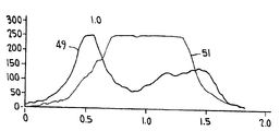
도 21및 도 22에 그려진 곡선은 곡선의 대략 상부가 전부 검은 255의 강도값에서 평평하게 되어있는 것을 제외하고는 도 20에 도시한 것과 유사한 변수에 기초한다. 도 21 및 도 22에서 분무형태(51)및 (53)의 최고강도 즉 밀도는 분무형태의 도너츠형상을 나타내는 분무형태(49)및 (52)의 고강도부와 대조된다.The curves drawn in FIGS. 21 and 22 are based on variables similar to those shown in FIG. 20 except that approximately the top of the curve is flat at the intensity value of 255 in black. 21 and 22, the highest strengths, or densities, of the spray forms 51 and 53 are contrasted with the high strength portions of spray forms 49 and 52, which exhibit the sprayed donut shape.
하기의 표 1은 Malvern Particle Sizer 에 의한 실험에 의해 얻어진 것 같은 프로브설계의 함수로서의 입자크기의 표이다. 실험을 실시함에 있어서, 0.14cc의 출력을 가지며 동일한 방출구크기를 갖는 도 1형의 펌프를 이용하였다. 사용된 매체는 Johnson & Jotnson의 No More Tangles였다.Table 1 below is a table of particle size as a function of probe design as obtained by experiments with Malvern Particle Sizer. In carrying out the experiment, the pump of Fig. 1 having an output of 0.14 cc and having the same discharge port size was used. The medium used was No More Tangles by Johnson & Jotnson.
펌프구조에서의 유일한 변수는 6개의 펌프의 각각에 본 발명에 따른 것을 포함한 여섯가지 다른 프로브설계가 사용된 스피너프로브였다. 따라서 펌프스프레이어중의 하나는 도 4의 설계의 표준프로브를 포함하고, 다른 펌프스프레이어중의 하나는 도 4의 설계의 표준프로브를 포함하고, 다른 펌프스프레이어는 도 5의 설계의 중공프로브를 가지고, 또 다른 펌프스프레이어는 도 7의 설계를 가지고, 또 다른 펌프스프레이어는 도 9의 설계를 가지며, 마지막으로 본 발명의 도 6에 따른 프로브설계를 갖는 펌프가 이용되었다.The only variable in the pump structure was the spinner probe, in which six different probe designs were used, each according to the invention, in each of the six pumps. Thus one of the pump sprayers comprises a standard probe of the design of FIG. 4, one of the other pump sprayers comprises a standard probe of the design of FIG. 4, the other pump sprayer has a hollow probe of the design of FIG. 5, Another pump sprayer has the design of FIG. 7, another pump sprayer has the design of FIG. 9, and finally a pump having a probe design according to FIG. 6 of the present invention was used.
[표 1]TABLE 1
프로브설계의 함수로서의 입자크기Particle Size as a Function of Probe Design

상기 표 1에 기재된 값은 Malvern 입자크기 데이터를 나타낸다. SMD값은 면적에 대한 체적의 비가 전제분무의 면적에 대한 체적의 비와 동일한 방울의 직경인 Sauter Mean Diameter이다. D(v,0.5)값은 평균질량직경이다.The values listed in Table 1 above represent Malvern particle size data. The SMD value is Sauter Mean Diameter, which is the diameter of the drop equal to the ratio of volume to area of the total spray. The value of D (v, 0.5) is the mean mass diameter.
중공프로브를 사용하여 직경과 진원도에서 보다 일정한 분부형태가 관찰되었으나 도5의 중공프로브는 입자크기의 면에 있어서 전혀 영향을 주지 않았음을 알 수 있다.Although a more uniform portion was observed in diameter and roundness using the hollow probe, it can be seen that the hollow probe of FIG. 5 had no effect on the particle size.
도 7, 도 8 및 도 9의 3개의 종래의 프로브는 SMD와 평균질량직경의 면에서 거의 영향을 주지 않았다.The three conventional probes of FIGS. 7, 8 and 9 had little effect in terms of SMD and average mass diameter.
본 발명에 따른 별형상의 중공프로브(도 6의 값)는 분무형태의 평균직경을 감소시키고, 입자크기분포를 보다 큰 방울크기 쪽으로 변화시키고, 평균방울크기(SMD 및 D(v,0.5)를 약10㎛만큼 증가시켰다.Star shaped hollow probe according to the present invention (value in Figure 6) to reduce the average diameter of the spray form, change the particle size distribution toward the larger droplet size, and the average droplet size (SMD and D (v, 0.5) Increased by about 10 μm.
본 발명에 따른 별형상의 프로브는 상술한 바와 같이 도 14, 도 16 및 도 18에 도시한 결과와 비교하여 도 15, 도 17 및 도 19에서 확인된 바와 같이 가장 굵은 입자크기를 얻었다.As described above, the star-shaped probe according to the present invention obtained the thickest particle size as confirmed in FIGS. 15, 17, and 19 as compared with the results shown in FIGS. 14, 16, and 18.
내부에 돌출부가 형성된 감쇠챔버를 갖는 부분들은 일체로 몰딩된 플라스틱부이지만 본 발명이 몰딩에 의한 돌출부(44)의 형성에 제한되는 것은 아니다.Portions having damping chambers formed therein with protrusions are integrally molded plastic parts, but the present invention is not limited to the formation of the
상기 기술에 비추어 보면 당연히 본 별명의 그외의 다른 변형 및 수정이 만들어질 수 있다. 따라서 첨부된 특허청구의 범위내에서 본 발명은 상술한 것이외의 방식으로 실시될 수 있음을 이해할 수 있을 것이다.In the light of the above description, other variations and modifications may, of course, be made. It is, therefore, to be understood that within the scope of the appended claims, the invention may be practiced otherwise than as described above.
도 1은 본 발명을 이용한 공지의 수동펌프스프레이어의 부분수직단면도.1 is a partial vertical cross-sectional view of a known manual pump sprayer using the present invention.
도 2는 본 발명을 이용한 트리거작동펌프스프레이어의 노즐부 부분수직 단면도.Figure 2 is a partial vertical cross-sectional view of the nozzle portion of the triggering pump sprayer using the present invention.
도 3은 도 2의 선 3-3을 따라서 취한 단면도.3 is a cross-sectional view taken along line 3-3 of FIG.
도 4는 종래기술에 따른 속이 찬 스피너프로브이의 사시도.Figure 4 is a perspective view of a solid spinner probe according to the prior art.
도 5는 중공의 매끈한 벽의 캐비티를 갖는 스피너프로브의 사시도.5 is a perspective view of a spinner probe with a hollow smooth wall cavity.
도 6은 스피너프로브만을 도 1의 선 6-6을 따라서 취한 단부도.6 is an end view of the spinner probe taken along line 6-6 of FIG.
도 7, 도 8 및 도 9는 종개기술에 따른 스피너프로브의 단부도.7, 8 and 9 are end views of the spinner probe according to the closing technique.
도 10은 본 발명을 이용한 트리거작동펌프스프레이어의 부분단면측면도.Figure 10 is a partial cross-sectional side view of the trigger operation pump sprayer using the present invention.
도 11은 본 발명을 이용한 스프레이어의 노즐단부의 확대단면도.Figure 11 is an enlarged cross-sectional view of the nozzle end of the sprayer using the present invention.
도 12는 노즐캡의 1회전위치에서 도 11의 선 12-12를 따라서 취한 단면도.12 is a sectional view taken along line 12-12 of FIG. 11 in one rotational position of the nozzle cap;
도 13은 대상물의 수직단면과 노즐방출구로부터 나오는 원추형분무형태를 나타내는 도면.Fig. 13 is a view showing the cone-shaped spray form coming out from the vertical section of the object and the nozzle discharge port;
도 14, 도 16 및 도 18은 대상물로부터 방출구사이의 여러가지 거리에서 도 13의 선 x-x를 따라서 취한 종래기술에 따라서 생성된 분무형태를 나타내는 도면.14, 16 and 18 show the spray pattern produced according to the prior art taken along the line x-x of FIG. 13 at various distances between the object and the outlet.
도 15, 도 17 및 도 19는 종개기술의 형태와 대조적으로 대상물로부터 방출구사이의 동일거리에서 도 13의 선 x-x를 따라서 취한 본 발명에 따라서 생성된 분무형태를 나타내는 도면.Figures 15, 17 and 19 show the spray form produced according to the invention taken along the line x-x of Figure 13 at the same distance between the outlet and the object as opposed to the form of the closure technique.
도 20, 도 21, 및 도 22는 도 14, 도 16 및 도 18의 붐무형태에 의해 생성된 것과 대조하여 도 15, 도 17 및 도 19의 분무형태에 의해 얻어진 스프레이 강도를 나타내는 그래프.20, 21 and 22 are graphs showing the spray strength obtained by the spray form of FIGS. 15, 17 and 19 in contrast to that produced by the boomless form of FIGS. 14, 16 and 18.
** 도면의 주요부분에 대한 부호의 설명 **** Explanation of symbols for main parts of drawings **
30.....중공피스톤스템, 31.....플런저 헤드,30 .... hollow piston stem, 31 .... plunger head,
32.....프로브, 33.....노즐캠,32 ..... Probe, 33 .... Nozzle Cam,
34.....스커트부, 35.....단부벽,34 ..... skirt, 35 ..... end wall,
36.....방출구, 37.....스핀챔버,36 ..... outlet, 37 ..... spin chamber,
38.....원통형측벽, 39.....접선방향홈,38 ..... cylindrical side wall, 39 .. tangential groove,
41.....유체채널, 42.....방출로,41 .. fluid channels, 42 ..
43.....감쇠챔버, 44.....돌출부,43 ..... attenuation chamber, 44 ..... projection,
45.....트리거작동스프레이어, 46.....대상물(평면),45 ..... triggered sprayer, 46 ..... object (plane),
47,48,49,51,52,53.....분무형태, 132.....프로브,47,48,49,51,52,53 ..... spray form, 132 ..... probe,
Claims (4)
Applications Claiming Priority (2)
| Application Number | Priority Date | Filing Date | Title |
|---|---|---|---|
| US08/620,855 US5738282A (en) | 1996-03-20 | 1996-03-20 | Pump sprayer nozzle for producing a solid spray pattern |
| US08/620,855 | 1996-03-20 |
Publications (2)
| Publication Number | Publication Date |
|---|---|
| KR970064733A KR970064733A (en) | 1997-10-13 |
| KR100504082B1 true KR100504082B1 (en) | 2005-10-05 |
Family
ID=24487698
Family Applications (1)
| Application Number | Title | Priority Date | Filing Date |
|---|---|---|---|
| KR1019970002383A Expired - Fee Related KR100504082B1 (en) | 1996-03-20 | 1997-01-28 | Manual Pump Sprayer |
Country Status (13)
| Country | Link |
|---|---|
| US (1) | US5738282A (en) |
| EP (1) | EP0796661B1 (en) |
| JP (1) | JP3223131B2 (en) |
| KR (1) | KR100504082B1 (en) |
| CN (1) | CN1082394C (en) |
| AR (1) | AR006231A1 (en) |
| AU (1) | AU705868B2 (en) |
| BR (1) | BR9700346A (en) |
| CA (1) | CA2195503C (en) |
| DE (1) | DE69715277T2 (en) |
| ES (1) | ES2179262T3 (en) |
| IN (1) | IN191528B (en) |
| TW (1) | TW340061B (en) |
Families Citing this family (37)
| Publication number | Priority date | Publication date | Assignee | Title |
|---|---|---|---|---|
| FR2729091B1 (en) * | 1995-01-11 | 1997-05-30 | Valois | SPRAY NOZZLE |
| ES2130943B1 (en) * | 1996-06-18 | 2000-02-16 | Fico Transpar Sa | SPRAY DEVICE FOR WINDSHIELD WASHERS OF AUTOMOBILE VEHICLES. |
| FR2772644B1 (en) * | 1997-12-24 | 2000-02-04 | D Investissement Ind Et Commer | SPRAY NOZZLE WITH STATIC MEANS OF FLOW INHIBITION |
| FR2793222B1 (en) * | 1999-05-05 | 2001-07-06 | Oreal | DISTRIBUTION HEAD AND CONTAINER THUS EQUIPPED |
| IL133226A (en) * | 1999-11-30 | 2004-08-31 | Mamtirim Dan | Vortex liquid-atomizer |
| FR2838070B1 (en) * | 2002-04-04 | 2005-02-11 | Valois Sa | DISTRIBUTION HEAD TO BE MOUNTED ON A MOBILE HOLLOW ACTUATING ROD |
| US7017833B2 (en) * | 2003-02-04 | 2006-03-28 | Continental Afa Dispensing Company | Trigger sprayer spray, off, stream, off indexing nozzle assembly |
| FR2858568B1 (en) * | 2003-08-08 | 2006-09-15 | Valois Sas | LIQUID SPRAY HEAD |
| US20050048428A1 (en) * | 2003-08-25 | 2005-03-03 | Lim Walter K. | Device and method for extinguishing a candle flame |
| CN101218036B (en) * | 2005-07-06 | 2011-05-04 | 三谷阀门有限公司 | Content discharge mechanism, and aerosol-type product and pump-type product with the same |
| US8500044B2 (en) * | 2007-05-04 | 2013-08-06 | S.C. Johnson & Son, Inc. | Multiple nozzle differential fluid delivery head |
| US20070237864A1 (en) * | 2006-04-07 | 2007-10-11 | Conopco, Inc., D/B/A Unilever | Salad dressing product dispensed as a spray |
| US20070237878A1 (en) * | 2006-04-07 | 2007-10-11 | Conopco, Inc., D/B/A Unilever | Product containing vegetable oil and dispensing article |
| US7871217B2 (en) | 2006-12-12 | 2011-01-18 | The Clorox Company | Pump systems for pump dispensers |
| FR2909908B1 (en) * | 2006-12-15 | 2009-02-27 | Rexam Dispensing Systems Sas | SPRAY NOZZLE, DISPENSING MEMBER COMPRISING SUCH A NOZZLE, DISPENSER COMPRISING SUCH AN ORGAN AND USE OF SUCH A NOZZLE. |
| US8820664B2 (en) | 2007-05-16 | 2014-09-02 | S.C. Johnson & Son, Inc. | Multiple nozzle differential fluid delivery head |
| FR2917652B1 (en) * | 2007-06-19 | 2009-09-11 | Rexam Dispensing Systems Sas | SPRAY NOZZLE COMPRISING AXIAL GROOVES FOR BALANCED SUPPLY OF THE TOURBILLONARY CHAMBER |
| US9242256B2 (en) * | 2007-07-17 | 2016-01-26 | S.C. Johnson & Son, Inc. | Aerosol dispenser assembly having VOC-free propellant and dispensing mechanism therefor |
| FR2946326B1 (en) * | 2009-06-04 | 2011-08-05 | Rexam Dispensing Sys | PUSH BUTTON FOR A PRESSURIZED LIQUID DISTRIBUTION SYSTEM |
| FR2949762B1 (en) | 2009-09-10 | 2011-12-09 | Rexam Dispensing Sys | PUSH BUTTON FOR A SYSTEM FOR DISTRIBUTING A PRODUCT UNDER PRESSURE. |
| USD681470S1 (en) | 2010-01-08 | 2013-05-07 | Oms Investments, Inc. | Dispensing container |
| USD628900S1 (en) | 2010-02-19 | 2010-12-14 | Medtech Products, Inc. | Spray nozzle |
| USD628899S1 (en) | 2010-02-19 | 2010-12-14 | Medtech Products, Inc. | Spray nozzle |
| USD628901S1 (en) | 2010-02-19 | 2010-12-14 | Medtech Products, Inc. | Spray nozzle |
| USD628898S1 (en) | 2010-02-19 | 2010-12-14 | Medtech Products, Inc. | Spray nozzle |
| US20120223161A1 (en) | 2011-03-01 | 2012-09-06 | Smg Brands, Inc. | Ready-to-use hose end sprayer |
| US20120223160A1 (en) | 2011-03-01 | 2012-09-06 | Smg Brands, Inc. | Applicator with collapsible wand |
| USD670982S1 (en) | 2011-03-01 | 2012-11-20 | Smg Brands, Inc. | Applicator |
| USD650046S1 (en) | 2011-03-01 | 2011-12-06 | Smg Brands, Inc. | Sprayer |
| FR2994866B1 (en) * | 2012-09-04 | 2019-08-23 | Aptar France Sas | FLUID SPRAY HEAD AND DISPENSER COMPRISING SUCH A SPRAY HEAD. |
| USD708301S1 (en) | 2013-03-15 | 2014-07-01 | Oms Investments, Inc. | Liquid sprayer |
| US9999895B2 (en) | 2014-08-06 | 2018-06-19 | S. C. Johnson & Son, Inc. | Spray inserts |
| KR101661575B1 (en) * | 2014-10-22 | 2016-10-04 | (주)연우 | Spray orifice structure |
| US11426742B2 (en) * | 2020-01-28 | 2022-08-30 | Collins Engine Nozzles, Inc. | Spray nozzle |
| CN111992345A (en) * | 2020-08-19 | 2020-11-27 | 苏州瑞得恩光能科技有限公司 | Spray head |
| CN113601253B (en) * | 2021-07-07 | 2022-11-11 | 南京信息职业技术学院 | Cooling device for constructing continuous three-dimensional cooling area and use method |
| CN117000454A (en) * | 2023-07-31 | 2023-11-07 | 广西松浦电子科技有限公司 | Three-dimensional cyclone atomization device |
Citations (2)
| Publication number | Priority date | Publication date | Assignee | Title |
|---|---|---|---|---|
| US4706888A (en) * | 1986-07-11 | 1987-11-17 | Calmar, Inc. | Multi-purpose nozzle assembly |
| KR100375238B1 (en) * | 1994-10-20 | 2003-04-21 | 셍-고벵 칼마 인코퍼레이티드 | Atomizers can have different spray types |
Family Cites Families (5)
| Publication number | Priority date | Publication date | Assignee | Title |
|---|---|---|---|---|
| US3275248A (en) * | 1964-08-07 | 1966-09-27 | Spraying Systems Co | Modified full cone nozzle |
| US3785571A (en) * | 1972-05-05 | 1974-01-15 | Seaquist Valve Co | Mechanical breakup aerosol sprayer button |
| US4051983B1 (en) * | 1975-11-19 | 1993-12-14 | Calmar Inc. | Pump sprayer having pump priming means |
| US5152463A (en) * | 1991-10-08 | 1992-10-06 | Delavan Inc. | Aspirating simplex spray nozzle |
| US5593094A (en) * | 1995-02-07 | 1997-01-14 | Calmar Inc. | Pump sprayer having variable discharge |
-
1996
- 1996-03-20 US US08/620,855 patent/US5738282A/en not_active Expired - Lifetime
-
1997
- 1997-01-20 CA CA002195503A patent/CA2195503C/en not_active Expired - Lifetime
- 1997-01-28 KR KR1019970002383A patent/KR100504082B1/en not_active Expired - Fee Related
- 1997-01-29 AU AU12389/97A patent/AU705868B2/en not_active Expired
- 1997-02-04 ES ES97200307T patent/ES2179262T3/en not_active Expired - Lifetime
- 1997-02-04 DE DE69715277T patent/DE69715277T2/en not_active Expired - Lifetime
- 1997-02-04 EP EP97200307A patent/EP0796661B1/en not_active Expired - Lifetime
- 1997-02-12 TW TW086101521A patent/TW340061B/en not_active IP Right Cessation
- 1997-02-18 IN IN289CA1997 patent/IN191528B/en unknown
- 1997-03-04 BR BR9700346A patent/BR9700346A/en not_active IP Right Cessation
- 1997-03-12 CN CN97100887A patent/CN1082394C/en not_active Expired - Lifetime
- 1997-03-14 AR ARP970101023A patent/AR006231A1/en active IP Right Grant
- 1997-03-19 JP JP06617397A patent/JP3223131B2/en not_active Expired - Fee Related
Patent Citations (3)
| Publication number | Priority date | Publication date | Assignee | Title |
|---|---|---|---|---|
| US4706888A (en) * | 1986-07-11 | 1987-11-17 | Calmar, Inc. | Multi-purpose nozzle assembly |
| KR880001335A (en) * | 1986-07-11 | 1988-04-22 | 도날드 이.콕스 | Multi-Purpose Nozzle Assembly for Liquid Dispersers |
| KR100375238B1 (en) * | 1994-10-20 | 2003-04-21 | 셍-고벵 칼마 인코퍼레이티드 | Atomizers can have different spray types |
Also Published As
| Publication number | Publication date |
|---|---|
| IN191528B (en) | 2003-12-06 |
| JPH1015438A (en) | 1998-01-20 |
| ES2179262T3 (en) | 2003-01-16 |
| EP0796661A1 (en) | 1997-09-24 |
| MX9701437A (en) | 1997-09-30 |
| TW340061B (en) | 1998-09-11 |
| EP0796661B1 (en) | 2002-09-11 |
| BR9700346A (en) | 1998-10-27 |
| AR006231A1 (en) | 1999-08-11 |
| CA2195503C (en) | 2003-03-25 |
| DE69715277T2 (en) | 2003-05-28 |
| CA2195503A1 (en) | 1997-09-21 |
| CN1159963A (en) | 1997-09-24 |
| AU705868B2 (en) | 1999-06-03 |
| JP3223131B2 (en) | 2001-10-29 |
| US5738282A (en) | 1998-04-14 |
| AU1238997A (en) | 1997-09-25 |
| KR970064733A (en) | 1997-10-13 |
| CN1082394C (en) | 2002-04-10 |
| DE69715277D1 (en) | 2002-10-17 |
Similar Documents
| Publication | Publication Date | Title |
|---|---|---|
| KR100504082B1 (en) | Manual Pump Sprayer | |
| CN1059610C (en) | Sprayer having variable spray pattern | |
| CN1305582C (en) | Telescopic foaming agent nozzle | |
| US5878959A (en) | Nozzle for pump dispensers | |
| CA1316154C (en) | Foam-off nozzle assembly with barrel screen insert for use in a trigger sprayer | |
| KR102168146B1 (en) | Full cone air-assisted spray nozzle assembly | |
| EP0718041B1 (en) | Foamer nozzle for fluid dispenser | |
| KR20040100930A (en) | Dual sprayer with external mixing chamber | |
| CN109070109B (en) | Improved Swirl Nozzle Assemblies Using Mechanical Disintegration to Generate a Fog Spray of Uniform Droplets | |
| JPH08243449A (en) | Pump type spray | |
| US4883227A (en) | Foamer nozzle assembly with air passageway | |
| US5366160A (en) | Foamer nozzle with looped rib flow disrupters | |
| JP3401267B2 (en) | Media discharge nozzle | |
| US5234167A (en) | One-piece foamer nozzle | |
| MXPA97001437A (en) | Spray nozzle with pump to produce solid aspers unpatron | |
| JPS61209067A (en) | Foaming dispersion method and pump used for executing said method | |
| MXPA95004420A (en) | Sprayer who has a variable spray pattern | |
| WO2025216051A1 (en) | Content spray device, pump-type product, and aerosol-type product | |
| AU625077C (en) | Foam-off nozzle assembly with barrel screen insert for use in a trigger sprayer | |
| JPS6211566A (en) | Hand-operated atomizer |
Legal Events
| Date | Code | Title | Description |
|---|---|---|---|
| PA0109 | Patent application |
St.27 status event code: A-0-1-A10-A12-nap-PA0109 |
|
| R17-X000 | Change to representative recorded |
St.27 status event code: A-3-3-R10-R17-oth-X000 |
|
| PG1501 | Laying open of application |
St.27 status event code: A-1-1-Q10-Q12-nap-PG1501 |
|
| PN2301 | Change of applicant |
St.27 status event code: A-3-3-R10-R13-asn-PN2301 St.27 status event code: A-3-3-R10-R11-asn-PN2301 |
|
| A201 | Request for examination | ||
| PA0201 | Request for examination |
St.27 status event code: A-1-2-D10-D11-exm-PA0201 |
|
| D13-X000 | Search requested |
St.27 status event code: A-1-2-D10-D13-srh-X000 |
|
| E902 | Notification of reason for refusal | ||
| PE0902 | Notice of grounds for rejection |
St.27 status event code: A-1-2-D10-D21-exm-PE0902 |
|
| D14-X000 | Search report completed |
St.27 status event code: A-1-2-D10-D14-srh-X000 |
|
| T11-X000 | Administrative time limit extension requested |
St.27 status event code: U-3-3-T10-T11-oth-X000 |
|
| T11-X000 | Administrative time limit extension requested |
St.27 status event code: U-3-3-T10-T11-oth-X000 |
|
| T11-X000 | Administrative time limit extension requested |
St.27 status event code: U-3-3-T10-T11-oth-X000 |
|
| T11-X000 | Administrative time limit extension requested |
St.27 status event code: U-3-3-T10-T11-oth-X000 |
|
| T11-X000 | Administrative time limit extension requested |
St.27 status event code: U-3-3-T10-T11-oth-X000 |
|
| P11-X000 | Amendment of application requested |
St.27 status event code: A-2-2-P10-P11-nap-X000 |
|
| P13-X000 | Application amended |
St.27 status event code: A-2-2-P10-P13-nap-X000 |
|
| T11-X000 | Administrative time limit extension requested |
St.27 status event code: U-3-3-T10-T11-oth-X000 |
|
| T11-X000 | Administrative time limit extension requested |
St.27 status event code: U-3-3-T10-T11-oth-X000 |
|
| T11-X000 | Administrative time limit extension requested |
St.27 status event code: U-3-3-T10-T11-oth-X000 |
|
| T11-X000 | Administrative time limit extension requested |
St.27 status event code: U-3-3-T10-T11-oth-X000 |
|
| T11-X000 | Administrative time limit extension requested |
St.27 status event code: U-3-3-T10-T11-oth-X000 |
|
| T11-X000 | Administrative time limit extension requested |
St.27 status event code: U-3-3-T10-T11-oth-X000 |
|
| T11-X000 | Administrative time limit extension requested |
St.27 status event code: U-3-3-T10-T11-oth-X000 |
|
| T11-X000 | Administrative time limit extension requested |
St.27 status event code: U-3-3-T10-T11-oth-X000 |
|
| T11-X000 | Administrative time limit extension requested |
St.27 status event code: U-3-3-T10-T11-oth-X000 |
|
| P11-X000 | Amendment of application requested |
St.27 status event code: A-2-2-P10-P11-nap-X000 |
|
| P13-X000 | Application amended |
St.27 status event code: A-2-2-P10-P13-nap-X000 |
|
| E701 | Decision to grant or registration of patent right | ||
| PE0701 | Decision of registration |
St.27 status event code: A-1-2-D10-D22-exm-PE0701 |
|
| GRNT | Written decision to grant | ||
| PR0701 | Registration of establishment |
St.27 status event code: A-2-4-F10-F11-exm-PR0701 |
|
| PR1002 | Payment of registration fee |
St.27 status event code: A-2-2-U10-U11-oth-PR1002 Fee payment year number: 1 |
|
| PG1601 | Publication of registration |
St.27 status event code: A-4-4-Q10-Q13-nap-PG1601 |
|
| PR1001 | Payment of annual fee |
St.27 status event code: A-4-4-U10-U11-oth-PR1001 Fee payment year number: 4 |
|
| FPAY | Annual fee payment |
Payment date: 20090714 Year of fee payment: 5 |
|
| PR1001 | Payment of annual fee |
St.27 status event code: A-4-4-U10-U11-oth-PR1001 Fee payment year number: 5 |
|
| LAPS | Lapse due to unpaid annual fee | ||
| PC1903 | Unpaid annual fee |
St.27 status event code: A-4-4-U10-U13-oth-PC1903 Not in force date: 20100720 Payment event data comment text: Termination Category : DEFAULT_OF_REGISTRATION_FEE |
|
| PC1903 | Unpaid annual fee |
St.27 status event code: N-4-6-H10-H13-oth-PC1903 Ip right cessation event data comment text: Termination Category : DEFAULT_OF_REGISTRATION_FEE Not in force date: 20100720 |
|
| P22-X000 | Classification modified |
St.27 status event code: A-4-4-P10-P22-nap-X000 |