KR100365587B1 - Molds, dies or forming tools formed by thermal spraying - Google Patents
Molds, dies or forming tools formed by thermal spraying Download PDFInfo
- Publication number
- KR100365587B1 KR100365587B1 KR1019970703761A KR19970703761A KR100365587B1 KR 100365587 B1 KR100365587 B1 KR 100365587B1 KR 1019970703761 A KR1019970703761 A KR 1019970703761A KR 19970703761 A KR19970703761 A KR 19970703761A KR 100365587 B1 KR100365587 B1 KR 100365587B1
- Authority
- KR
- South Korea
- Prior art keywords
- mold
- support member
- die according
- tool
- metallic
- Prior art date
- Legal status (The legal status is an assumption and is not a legal conclusion. Google has not performed a legal analysis and makes no representation as to the accuracy of the status listed.)
- Expired - Fee Related
Links
Images


Classifications
-
- B—PERFORMING OPERATIONS; TRANSPORTING
- B29—WORKING OF PLASTICS; WORKING OF SUBSTANCES IN A PLASTIC STATE IN GENERAL
- B29C—SHAPING OR JOINING OF PLASTICS; SHAPING OF MATERIAL IN A PLASTIC STATE, NOT OTHERWISE PROVIDED FOR; AFTER-TREATMENT OF THE SHAPED PRODUCTS, e.g. REPAIRING
- B29C33/00—Moulds or cores; Details thereof or accessories therefor
- B29C33/02—Moulds or cores; Details thereof or accessories therefor with incorporated heating or cooling means
- B29C33/04—Moulds or cores; Details thereof or accessories therefor with incorporated heating or cooling means using liquids, gas or steam
-
- B—PERFORMING OPERATIONS; TRANSPORTING
- B22—CASTING; POWDER METALLURGY
- B22C—FOUNDRY MOULDING
- B22C9/00—Moulds or cores; Moulding processes
- B22C9/02—Sand moulds or like moulds for shaped castings
- B22C9/04—Use of lost patterns
-
- B—PERFORMING OPERATIONS; TRANSPORTING
- B22—CASTING; POWDER METALLURGY
- B22C—FOUNDRY MOULDING
- B22C9/00—Moulds or cores; Moulding processes
- B22C9/06—Permanent moulds for shaped castings
-
- B—PERFORMING OPERATIONS; TRANSPORTING
- B22—CASTING; POWDER METALLURGY
- B22C—FOUNDRY MOULDING
- B22C9/00—Moulds or cores; Moulding processes
- B22C9/06—Permanent moulds for shaped castings
- B22C9/065—Cooling or heating equipment for moulds
-
- B—PERFORMING OPERATIONS; TRANSPORTING
- B29—WORKING OF PLASTICS; WORKING OF SUBSTANCES IN A PLASTIC STATE IN GENERAL
- B29C—SHAPING OR JOINING OF PLASTICS; SHAPING OF MATERIAL IN A PLASTIC STATE, NOT OTHERWISE PROVIDED FOR; AFTER-TREATMENT OF THE SHAPED PRODUCTS, e.g. REPAIRING
- B29C33/00—Moulds or cores; Details thereof or accessories therefor
- B29C33/38—Moulds or cores; Details thereof or accessories therefor characterised by the material or the manufacturing process
- B29C33/3842—Manufacturing moulds, e.g. shaping the mould surface by machining
-
- B—PERFORMING OPERATIONS; TRANSPORTING
- B29—WORKING OF PLASTICS; WORKING OF SUBSTANCES IN A PLASTIC STATE IN GENERAL
- B29C—SHAPING OR JOINING OF PLASTICS; SHAPING OF MATERIAL IN A PLASTIC STATE, NOT OTHERWISE PROVIDED FOR; AFTER-TREATMENT OF THE SHAPED PRODUCTS, e.g. REPAIRING
- B29C33/00—Moulds or cores; Details thereof or accessories therefor
- B29C33/56—Coatings, e.g. enameled or galvanised; Releasing, lubricating or separating agents
- B29C33/565—Consisting of shell-like structures supported by backing material
-
- C—CHEMISTRY; METALLURGY
- C23—COATING METALLIC MATERIAL; COATING MATERIAL WITH METALLIC MATERIAL; CHEMICAL SURFACE TREATMENT; DIFFUSION TREATMENT OF METALLIC MATERIAL; COATING BY VACUUM EVAPORATION, BY SPUTTERING, BY ION IMPLANTATION OR BY CHEMICAL VAPOUR DEPOSITION, IN GENERAL; INHIBITING CORROSION OF METALLIC MATERIAL OR INCRUSTATION IN GENERAL
- C23C—COATING METALLIC MATERIAL; COATING MATERIAL WITH METALLIC MATERIAL; SURFACE TREATMENT OF METALLIC MATERIAL BY DIFFUSION INTO THE SURFACE, BY CHEMICAL CONVERSION OR SUBSTITUTION; COATING BY VACUUM EVAPORATION, BY SPUTTERING, BY ION IMPLANTATION OR BY CHEMICAL VAPOUR DEPOSITION, IN GENERAL
- C23C4/00—Coating by spraying the coating material in the molten state, e.g. by flame, plasma or electric discharge
-
- F—MECHANICAL ENGINEERING; LIGHTING; HEATING; WEAPONS; BLASTING
- F28—HEAT EXCHANGE IN GENERAL
- F28F—DETAILS OF HEAT-EXCHANGE AND HEAT-TRANSFER APPARATUS, OF GENERAL APPLICATION
- F28F13/00—Arrangements for modifying heat-transfer, e.g. increasing, decreasing
- F28F13/003—Arrangements for modifying heat-transfer, e.g. increasing, decreasing by using permeable mass, perforated or porous materials
-
- B—PERFORMING OPERATIONS; TRANSPORTING
- B29—WORKING OF PLASTICS; WORKING OF SUBSTANCES IN A PLASTIC STATE IN GENERAL
- B29C—SHAPING OR JOINING OF PLASTICS; SHAPING OF MATERIAL IN A PLASTIC STATE, NOT OTHERWISE PROVIDED FOR; AFTER-TREATMENT OF THE SHAPED PRODUCTS, e.g. REPAIRING
- B29C33/00—Moulds or cores; Details thereof or accessories therefor
- B29C33/38—Moulds or cores; Details thereof or accessories therefor characterised by the material or the manufacturing process
- B29C33/3842—Manufacturing moulds, e.g. shaping the mould surface by machining
- B29C33/3857—Manufacturing moulds, e.g. shaping the mould surface by machining by making impressions of one or more parts of models, e.g. shaped articles and including possible subsequent assembly of the parts
- B29C2033/3864—Spraying at least one layer to create the mould
-
- B—PERFORMING OPERATIONS; TRANSPORTING
- B29—WORKING OF PLASTICS; WORKING OF SUBSTANCES IN A PLASTIC STATE IN GENERAL
- B29C—SHAPING OR JOINING OF PLASTICS; SHAPING OF MATERIAL IN A PLASTIC STATE, NOT OTHERWISE PROVIDED FOR; AFTER-TREATMENT OF THE SHAPED PRODUCTS, e.g. REPAIRING
- B29C33/00—Moulds or cores; Details thereof or accessories therefor
- B29C33/38—Moulds or cores; Details thereof or accessories therefor characterised by the material or the manufacturing process
- B29C33/3807—Resin-bonded materials, e.g. inorganic particles
-
- B—PERFORMING OPERATIONS; TRANSPORTING
- B29—WORKING OF PLASTICS; WORKING OF SUBSTANCES IN A PLASTIC STATE IN GENERAL
- B29C—SHAPING OR JOINING OF PLASTICS; SHAPING OF MATERIAL IN A PLASTIC STATE, NOT OTHERWISE PROVIDED FOR; AFTER-TREATMENT OF THE SHAPED PRODUCTS, e.g. REPAIRING
- B29C33/00—Moulds or cores; Details thereof or accessories therefor
- B29C33/38—Moulds or cores; Details thereof or accessories therefor characterised by the material or the manufacturing process
- B29C33/3814—Porous moulds
Landscapes
- Engineering & Computer Science (AREA)
- Mechanical Engineering (AREA)
- Chemical & Material Sciences (AREA)
- Manufacturing & Machinery (AREA)
- Physics & Mathematics (AREA)
- Metallurgy (AREA)
- Chemical Kinetics & Catalysis (AREA)
- Materials Engineering (AREA)
- Plasma & Fusion (AREA)
- Organic Chemistry (AREA)
- Dispersion Chemistry (AREA)
- Thermal Sciences (AREA)
- General Engineering & Computer Science (AREA)
- Moulds For Moulding Plastics Or The Like (AREA)
- Coating By Spraying Or Casting (AREA)
- Application Of Or Painting With Fluid Materials (AREA)
- Mold Materials And Core Materials (AREA)
- Blow-Moulding Or Thermoforming Of Plastics Or The Like (AREA)
Abstract
a) 열교환 본체 지지부재(12) 및 b) 지지부재에서 원하는 구조로 금속성 입자(28)을 용사하여 형성되는 지지부재(12)내의 성형캐비티부분(14)으로 이루어지는 몰드, 다이 및 성형공구를 개시한다. 또한, a) 몰드, 다이나 성형공구의 열전달능력을 강화하도록 제어되고 설정된 공극률을 갖는 본체지지부재(12)를 제공하는 단계; b) 원하는 캐비티에 지지부재(12)의 표면을 구성하는 단계; 및 c) 지지부재(12)에서 구성된 캐비티에 입자(28)를 분사하여 몰드, 다이나 성형공구를 제조하는 단계로 이루어지는 몰드, 다이나 성형공구를 제조하는 방법을 기술한다.a) a mold, a die and a molding tool comprising a forming cavity portion 14 in a support member 12 formed by thermally spraying metallic particles 28 in a desired structure from a heat exchange body support member 12 and b) a support member; do. Also, a) providing a body support member 12 having a controlled and set porosity to enhance the heat transfer capability of the mold, dynamo-tool; b) constructing the surface of the support member 12 in the desired cavity; And c) spraying the particles 28 in the cavity constituted by the support member 12 to produce a mold, a dynamo molding tool.

Description
몰드는 일반적으로 금속성이며, 본체부분과 캐비티 부분으로 이루어진다. 성형조작에 있어서 생산성을 증가시키기 위해서는 성형공정동안 발생된 열을 방산하는 것이 중요한 역할을 한다. 즉, 성형 조작에서 열의 분산이 빠를수록 성형동안 주기 시간이 더 빠르게 증가될 수 있다.The mold is generally metallic and consists of a body portion and a cavity portion. In the molding operation, dissipating heat generated during the molding process plays an important role. In other words, the faster the heat dissipation in the molding operation, the faster the cycle time can be increased during molding.
성형은 조형(shaping)방법과 같이 금속성 물품을 제조하기 위한 기술로서 사용된다. 또한 성형은 일반적으로 플라스틱 물질인 열가소성 및 열경화성 그리고 탄성중합성 물질의 형성에 대하여 사용된다.Molding is used as a technique for making metallic articles, such as in shaping methods. Molding is also used for the formation of thermoplastic and thermoset and elastomeric materials, which are generally plastic materials.
용사(溶射; thermal spraying)는 일반적으로 세분하게 구분된 금속성이나 비금속성 표면 물질을 제조된 기판위에 용융이나 반용융된 상태로 용착하여 스프레이 용착을 형성하는 방법들의 한종류이다. "용사"는 일반적으로 아크용사, 플레임용사 및 플라즈마용사라고 하는 다른 방법에 사용되는 용어이다. 용사건(gun)은 연소성 기체나 전기적 아크를 사용하여 필요한 열을 발생시킨다. 물질을 가열함으로써 그들은 플라스틱이나 용융상태로 변화되고 압축기체에 의해 가속화된다. 제한된 입자의 흐름이 기판으로 이송된다. 입자는 표면을 때려 제조된 표면의 요철과 서로 같은 모양으로 하여 부착된 얇은 작은판(스플래트)을 고르게 하고 형성한다. 기판상에 분사된 입자가 충돌함으로써, 입자는 냉각되고 입자위에 입자 즉, 라멜라 구조로 집적되어 코팅을 형성한다(미국 용접학회(마이애미, 플로리다)에서 출판된 "용사" 실용, 이론 및 응용(1995) 참조).Thermal spraying is a type of method for forming spray welding by generally depositing finely divided metallic or nonmetallic surface materials on a manufactured substrate in a molten or semi-melted state. "Sprayed" is a term generally used in other methods, such as arc spraying, flame spraying, and plasma spraying. Guns use combustible gases or electric arcs to generate the required heat. By heating the materials they are converted into plastic or molten state and accelerated by the compressor body. Limited particle flow is transferred to the substrate. The particles hit the surface in the same shape as the unevenness of the produced surface to form and form a thin plate (split) attached thereto. As the particles sprayed onto the substrate collide, the particles cool and accumulate onto the particles, or lamellar structures, to form a coating. ) Reference).
플라즈마용사는 비전달 아크가 워크피스에 피복물질을 용융하고 피복하는 가스를 이온화하는 열원으로서 활용되는 용사방법이다.Plasma spraying is a thermal spraying method in which a non-transfer arc is utilized as a heat source to melt a coating material on a workpiece and ionize a gas to coat the workpiece.
플레임용사는 산소연료가스 플레임이 서피싱물질을 용융하기 위한 열원인 용사방법이다. 압축기체는 기판에 서피싱물질을 분무하고 피복하는데 사용될 수도 있거나 안될 수도 있다.Flame spraying is a thermal spraying method in which an oxy-fuel gas flame is a heat source for melting a surfacing material. The compressor body may or may not be used to spray and coat the surfacing material onto the substrate.
아크용사는 기판에 서피싱물질을 분무하고 피복하기 위해 열원으로서 서피싱물질의 두 개의 소모성 전극 사이의 아크와 압축기체를 사용하는 용사방법이다.Arc spraying is a thermal spraying method that uses an arc and a compressor body between two consumable electrodes of a surfacing material as a heat source to spray and coat the surfacing material on a substrate.
미국특허 제3,429,962호는 금속산화물 물품을 형성하는 용사기술을 개시한다. 예컨대 구리나 알루미늄의 회전가능한 멘드렐(15)에는 금속산화물을 도포하였다. 구리나 알루미늄 멘드렐을 계속해서 화학적으로 에칭하여 최종 제품을 얻었다. 목적하는 제품은 연료셀 전극으로서 활용된다. 유사한 경향으로 미국특허 제5,006,321호는 유리몰드플런저를 제조하기 위한 용사방법에 관한 것이다.U. S. Patent No. 3,429, 962 discloses a thermal spraying technique for forming a metal oxide article. For example, a rotatable mandrel 15 of copper or aluminum is coated with a metal oxide. The copper or aluminum mandrel was subsequently chemically etched to obtain the final product. The desired product is utilized as a fuel cell electrode. Similarly, U. S. Patent No. 5,006, 321 relates to a thermal spraying method for producing a glass mold plunger.
미국특허 제4,460,529호에서는 용사기술에 의해 세라믹 중공본체를 제조하는 방법을 기술한다. 세라믹 본체는 알루미늄과 티타늄탄화물, 붕화물, 질화물 및그것의 혼합물로 이루어진다. 적당한 코어 물질은 세라믹 물질과 결합하지 않도록 선택된다. 참고문헌에서는 중공본체로부터의 몰드코어의 분리능은 세라믹이나 세라믹 산화물층의 분리능에 비하여 더 높은 팽창계수를 갖는 코어의 선택에 의해 보장될 수 있다는 것이 제시된다.US Patent No. 4,460,529 describes a method for producing a hollow ceramic body by thermal spraying technology. The ceramic body consists of aluminum and titanium carbide, boride, nitride and mixtures thereof. Suitable core materials are selected to not bond with the ceramic material. The reference suggests that the resolution of the mold core from the hollow body can be ensured by the selection of a core with a higher coefficient of expansion compared to the resolution of the ceramic or ceramic oxide layer.
미국특허 제2,968,083호에서는 금속분사를 활용하는 내화구조의 핫패칭을 기술한다.U.S. Patent No. 2,968,083 describes hot patching of a refractory structure utilizing metal spraying.
흥미로운 다른 특허에는 미국특허 제5,290,373; 4,966,220; 5,000,244; 4,482,513; 4,304,747; 4,242,074; 4,547,415; 4,460,529; 3,916,418; 4,006,633; 및 3,609,829호가 포함된다.Other interesting patents include US Pat. No. 5,290,373; 4,966,220; 5,000,244; 4,482,513; 4,304,747; 4,242,074; 4,547,415; 4,460,529; 3,916,418; 4,006,633; And 3,609,829.
용사를 활용하는 스프레이 용착은 기판에 힘을 가하지 않는다고 언급되어 있다. (용사, 상기의 P16) 그러나 본 출원은 매우 빠르게 냉각될 수 있는 본체를 활용하고, 플라스틱과 금속성 물품을 성형하기 위해 몰드의 캐비티를 형성시 본체상에 용사의 사용하여 매우 높은 강도를 갖는 몰드의 설계를 고려한 것이다.It is mentioned that spray deposition utilizing thermal spraying does not exert a force on the substrate. (Spray, P16 above) However, the present application utilizes a body that can be cooled very quickly, and uses a spray on the body to form a cavity of the mold for molding plastic and metallic articles, thereby forming a mold having a very high strength. The design is considered.
본 발명의 목적은 본체부분과 용사기술로 본체 부분내에 형성되는 캐비티 부분을 갖는 몰드나 다이를 기술하는 것이다.It is an object of the present invention to describe a mold or die having a body portion and a cavity portion formed in the body portion by thermal spraying techniques.
본 발명의 다른 목적은 본체 부분과 용사기술에 의해 형성된 캐비티 부분을 갖는 몰드나 다이의 제조를 기술하는 것이다.Another object of the present invention is to describe the manufacture of a mold or die having a body portion and a cavity portion formed by a thermal spraying technique.
본 발명의 또다른 목적은 본체부분과 본체부분에 금속성 입자를 용사하여 형성된 캐비티 부분을 갖는 몰드에서 원하는 물질을 성형함으로써 플라스틱이나 금속성 부를 제조하는 것을 기술하는 것이다.It is another object of the present invention to describe the manufacture of plastic or metallic parts by molding the desired material in a mold having a body portion and a cavity portion formed by spraying metallic particles on the body portion.
본 발명의 추가의 목적은 본체에 대한 냉각수단의 형성에서 매우 높은 냉각속도와 높은 가요성을 허용하는 본 발명의 본체부분을 기술하는 것이다.It is a further object of the present invention to describe the body part of the invention which allows for very high cooling rates and high flexibility in the formation of cooling means for the body.
본 발명은 몰드, 다이 및 다른 성형공구, 그들의 제조 및 금속제조와 플라스틱 제조에서의 그들의 사용분야에 관한 것이다.The present invention relates to molds, dies and other forming tools, their manufacture and their field of use in metal and plastics manufacturing.
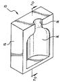
도 1은 본 발명의 몰드나 다이의 개략도이다.1 is a schematic view of a mold or die of the present invention.
도 2는 도 1의 선 2-2를 따라 취한 본 발명의 몰드나 다이의 단면도이다.2 is a cross-sectional view of a mold or die of the present invention taken along line 2-2 of FIG.
도 3은 본 발명의 몰드나 다이의 제조를 설명하는 개략적인 공정도이다.3 is a schematic process diagram illustrating the manufacture of a mold or die of the present invention.
도 4 및 도 5는 플라스틱 제품의 성형 및 분리에 대한 개략공정을 나타낸다.4 and 5 show schematic processes for forming and separating plastic products.
(a) 열교환 본체지지부재; 및(a) a heat exchange body support member; And
(b) 지지부재내에서, 지지부재에서 원하는 구조로 입자를 용사하여 형성된 성형캐비티 부분으로 이루어지는 몰드나 다이를 기술한다. 바람직하게는 입자들은 금속이나 고용융온도 플라스틱이다.(b) In the supporting member, a mold or a die consisting of a molding cavity portion formed by spraying particles into a desired structure in the supporting member is described. Preferably the particles are metal or high melting temperature plastics.
또한 (a) 열교환 본체지지부재를 제공하는 단계;(A) providing a heat exchange body support member;
(b) 원하는 캐비티에 지지부재의 표면을 구성하는 단계; 및(b) constructing a surface of the support member in a desired cavity; And
(c) 지지부재에서 구성된 캐비티에 금속성 입자를 용사하여 몰드를 제조하는 단계로 이루어지는 몰드나 다이 제조방법을 기술한다.(c) A method of manufacturing a mold or a die, comprising the steps of forming a mold by spraying metallic particles on the cavity formed in the support member.
본 발명은 넓게 몰드, 다이 및 다른 성형공구에 관한 것이다. 기술은 열가소성 수지, 열경화성 수지외에 유리, 금속 및 합금을 기초로 하는 부의 제조에 사용되는 공구에 적용된다.The present invention broadly relates to molds, dies and other forming tools. The technology is applied to tools used in the manufacture of parts based on glass, metals and alloys, in addition to thermoplastics, thermosetting resins.
금속에 있어서, 몰드수단공구는 오직 캐스팅용으로 만 사용된다. 다이는 포밍이나 아니면 캐스팅용으로 사용된다. 캐스팅(다이캐스팅과 같은)용과 금속의 성형(시트나 빌릿을 모양으로 압축하는 것과 같은)용 다이와 몰드를 제조할 수 있다.For metals, the tool means are used only for casting. Dies are used for forming or casting. Dies and molds for casting (such as die casting) and for molding metals (such as compressing sheets or billets into shapes) can be produced.
유리부 제조에 있어서, 이 기술이 적용가능한 몰드와 다이가 사용된다. 열가소성 수지를 기초로 하는 부에 있어서, 주요한 방법은 예컨대 압축성형, 트랜스퍼성형, 취입성형, 사출성형, 회전성형 및 열성형의 성형방법이라 불린다. 추가로 다이가 사용된다. 이들은 스탬핑 다이를 포함한다. 또한 압출다이는 예컨대 막, 시트 및 예컨대 튜브, 로드 및 상세한 모양의 이형품인 열가소성 수지계 부의 제조시 사용된다. 이 기술은 이들 모든 유형의 공구에 적용된다.In the manufacture of glass parts, molds and dies to which this technique is applicable are used. In the part based on the thermoplastic resin, the main method is called, for example, compression molding, transfer molding, blow molding, injection molding, rotational molding and thermoforming. In addition, a die is used. These include stamping dies. Extrusion dies are also used in the production of thermoplastic resin based parts, for example membranes, sheets and releases of detailed shapes, for example tubes, rods. This technique applies to all these types of tools.
열경화성 수지를 기초로 하는 부에 있어서, 방법은 부를 형성한 후 가교시켜 강도 및 관련특성을 얻기 위해 다이에 시트를 가압하는 것과 같은 부의 다이성형을 이용한다. 또한, 우레탄 발포시팅 등의 제조용과 같은 몰드를 갖는다. 이 기술은 이런 모든 공구를 제조하는데 적용된다.For a part based on a thermosetting resin, the method utilizes a part die forming such as pressing the sheet to the die to form the part and then crosslink to obtain strength and related properties. Moreover, it has a mold similar to manufacture for urethane foam seating. This technique applies to the manufacture of all these tools.
또한 인발성형, 필라멘트 권사, 구조반응, 사출성형 및 수지 트랜스퍼성형과 같은 특정부 제조방법이 있다. 이들 방법에서, 몰드나 다이를 사용할 수도 있다. 이 기술은 이런 공구의 제조에 적용된다.There are also methods for producing specific parts such as drawing, filament winding, structural reaction, injection molding and resin transfer molding. In these methods, a mold or a die may be used. This technique applies to the manufacture of such tools.
상기한 이들 모든 경우에서, 열전달효율과 열제어는 공구로 제조된 부의 제품품질과 제조 경제성의 요소이다. 또한, 이들 모든 경우에서 몰드, 다이나 성형공구의 제조코스트 및 소요시간은 확실하게 영향을 받는다.In all these cases, heat transfer efficiency and heat control are factors of the product quality and manufacturing economics of the parts made with the tool. In all of these cases, the production cost and time required for the mold, the dynamo-tool, are reliably influenced.
이 기술은 성형공구와 열가소성 수지, 열경화성 수지, 유리금속 및 합금부로 제조된 부에 대한 적용성에서 일반적인 것이다.This technique is common in applicability to molding tools and parts made of thermoplastics, thermosets, free metals and alloy parts.
본 발명의 몰드의 사용은 매우 쉽고 빠르게 냉각될 수 있는 본체부의 형성을고려한 것이다. 본체부가 이렇게 빠르게 냉각하는 이유는 몰드의 캐비티 부분이 용사기술의 사용으로 본체부에 도포되기 때문이다. 바람직하게는 용사는 금속성 부분의 본체에 형성된 것과 같은 기판에 직접 도포된다.The use of the mold of the present invention contemplates the formation of a body portion which can be cooled very easily and quickly. The reason why the body part cools so quickly is that the cavity portion of the mold is applied to the body part by the use of a thermal spraying technique. Preferably the thermal spray is applied directly to the substrate as formed in the body of the metallic portion.
또한 본 발명은 제어된 공극률로 형성된 본체부분의 활용을 특징으로 한다. 본체부분은 바람직하게는 발포 알루미늄이나 알루미늄합금과 같은 발포금속성 물질이나 쉽게 발포될 수 있는 다른 금속성 재료로 이루어진다. 이런 발포 알루미늄 합금은 캐나다의 알칸알루미늄이나 캘리포니아의 ERG로부터 시중구입가능하다.The invention also features the utilization of a body portion formed with a controlled porosity. The body portion preferably consists of a foamed metallic material such as foamed aluminum or an aluminum alloy or other metallic material that can be easily foamed. Such expanded aluminum alloys are commercially available from Alkanaluminium in Canada or ERG in California.
또한 본체부분은 스크린이나 메시물질과 같은 다른 금속성 물질로 이루어질 수도 있다. 활용될 수 있는 메시는 몰드의 캐비티 부분의 냉각제의 흐름을 가능한한 빠르게 하도록 오리피스의 크기를 다르게 하고, 여전히 동시에 성형 조작에 사용되도록 충분한 강도를 가져야 한다.The body portion may also be made of other metallic material, such as a screen or mesh material. The mesh that can be utilized must vary the size of the orifice to make the flow of coolant in the cavity portion of the mold as fast as possible and still have sufficient strength to be used in the molding operation at the same time.
본체 부분은 또한 다른 금속성 물질로 이루어질 수도 있다. 이런 물질중의 하나는 "타워 패킹 재료"로 일컫는다. 이 제품의 라인은 크래킹 축합 및 열전달용 표면을 생성하는데 석유화학업에서 주로 사용된다. 구조화된 패킹은 오클라호마 툴사의 하르스코 코퍼레이션 계열의 파터슨-켈리 컴퍼니의 누터 엔지니어링으로부터 구입가능하다. 이런 패킹재료는 "몬츠 B1" 또는 "A3"등으로 불리운다. 이러한 다른 재료는 누터 엔지니어링에서 "Nutter Ring Rardom Packing"으로 불리운다.누터링은 관통된 중심홈통, 플랜지화된 측면 및 상이한 직경의 두끝이 테이퍼된 간격 후프를 갖는 개방된 반고리를 갖는 것을 특징으로 한다. 활용될 수 있는 다른 패킹재료는 오하이오 아크론의 노턴 케미칼 프로세스 프로덕트제 "Intalox™고 성능 구조화 패킹"으로 불리운다 (Intalox™은 노턴 케미칼 프로세스 프로덕트의 상품명이다). Intalox™시스템은 마찬가지로 구리등과 같은 여러금속의 이중골시트 구조를 포함하는 Snowflakes™고성능 패킹을 갖는다. 또한 노턴 케미칼 프로세스 프로덕트에 의해 제공된 래시그 링(Raschig ring)은 동일하게 마찬가지로 하이팩금속 패킹이나 금속팔링을 적용할 수 있다. 노턴에 의해 공급된 다른 패킹재료는 구조화 패킹을 위한 상술한 다수의 재료를 활용한 "Flexipac"라 불리운다. 마찬가지로 구조화 패킹 재료용 "Koch Flexigrid"(Koch의 상품명)이나 밸브트레이용 "Flex- itray(Koch의 상품명)이나 "Flexiring"(압축된 패킹)과 같은 다른 재료가 사용될 수도 있다.The body portion may also be made of other metallic material. One such material is referred to as "tower packing material". This line of products is mainly used in the petrochemical industry to create surfaces for cracking condensation and heat transfer. Structured packings are available from Nuter Engineering of the Paterson-Kelly Company of Harsco Corporation in Oklahoma Tulsa. This packing material is called "Montz B1" or "A3". This other material is called "Nutter Ring Rardom Packing" in Nuter Engineering. Nutering is characterized by an open half-ring with a perforated central gutter, flanged sides and tapered spacing hoops at two ends of different diameters. Another packing material that may be utilized is called "Intalox ™ High Performance Structured Packing", manufactured by Akron, Ohio's Norton Chemical Process Products (Intalox ™ is a tradename of Norton Chemical Process Products). Intalox ™ systems likewise have Snowflakes ™ high performance packings that include a multi-corrugated double sheet structure such as copper. In addition, the Raschig ring provided by Norton Chemical Process Products may equally apply a high pack metal packing or metal ring. Another packing material supplied by Norton is called " Flexipac " utilizing a plurality of the above-described materials for structured packing. Similarly, other materials may be used, such as "Koch Flexigrid" (structured packing material) (Koch trade name), "Flex- itray" (Koch trade name) or "Flexiring" (compressed packing) for valve trays.
개방되고 다공성인 구성을 갖는 모든 재료에 관해서, 재료는 표면이 용사방법의 도포로 적합하게 제조될 수 있도록 구성되거나 압축되거나 원하는 크기로 분쇄될 필요가 있다는 것이 명백할 것이다.With respect to all materials having an open and porous configuration, it will be apparent that the material needs to be constructed, compressed or ground to the desired size so that the surface can be suitably produced by the application of a spraying method.
본 발명의 몰드 요소의 본체에 대하여 활용될 수도 있는 또 다른 재료는 소결된 금속펠트이다. 재료는 Feltmetal™(테크네틱스 코퍼레이션의 상품명(플로리다 델랜드))이란 상품명으로 시중구입가능하다. 섬유상 금속재료는 소결되고 다공성 시트의 형태로 제조된 랜덤 금속 섬유상 구조이다. 재료는 금속성 특성의 조합을 제공하고 여러 가지 지지체 적용에 대해서 적합한 섬유상 재료를 만든다. 섬유상 금속을 만드는 합금은 철, 크롬, 알루미늄, 유트리움, 스테인리스스틸, 니켈크롬합금, 니켈, 구리 및 티타늄과 그것의 합금일 수 있다. 재료는 일반적으로 부피당 75%-95%의 높은 공극율을 갖는다. 섬유상 금속재료는 활성표면 면적의 0.05m2/gm까지 투과가능하다. 예컨대, 스테인리스스틸재료는 10%의 밀도를 갖는 반면에 니켈금속섬유는 밀도 16%를 가질수도 있다. 적합한 재료는 금속부피의 cc당 표면의 4,000cm2의 표면적을 갖는 니켈 섬유인 TC3100일 수도 있다. 섬유상 금속재료의 열전도성은 이하의 표 1에 기술될 수 있다.Another material that may be utilized for the body of the mold element of the present invention is sintered metal felt. The material is commercially available under the trade name Feltmetal ™ (trade name of Technics Corporation, Florida). The fibrous metal material is a random metal fibrous structure sintered and manufactured in the form of a porous sheet. The material provides a combination of metallic properties and makes the fibrous material suitable for various support applications. The alloys that make up the fibrous metal may be iron, chromium, aluminum, eutriium, stainless steel, nickel chromium alloys, nickel, copper and titanium and alloys thereof. The material generally has a high porosity of 75% -95% per volume. The fibrous metal material is permeable up to 0.05 m 2 / gm of active surface area. For example, stainless steel material may have a density of 10%, while nickel metal fiber may have a density of 16%. Suitable materials may be TC3100, a nickel fiber having a surface area of 4,000 cm 2 of surface per cc of metal volume. The thermal conductivity of the fibrous metal material can be described in Table 1 below.

비교하기 위해, 고형니켈의 열전도성은 36.0 K BTU/시간/ft/℉인 반면에 302스테인리스 스틸은 9.4이다. 공기는 그것의 열전도성에 있어서 0.014이다(TD-882 섬유상 금속재료에 대한 테크네틱스 코포레이션 데이터 보고서로부터 유도된 데이터). 섬유상 금속재료는 그것의 높은 공극률로 인해 냉각이 용이하고 냉각도관의 배치를 위한 구조화가 용이하므로 바람직하다. 섬유상 금속은 성형성, 용접성, 충격 및 진동에 대한 저항성 및 인장과 압축 모두에서의 내하중력을 제공한다.For comparison, the thermal conductivity of solid nickel is 36.0 K BTU / hour / ft / ° F, while 302 stainless steel is 9.4. Air is 0.014 in its thermal conductivity (data derived from the Technics Corporation Data Report on TD-882 fibrous metal materials). The fibrous metal material is preferred because of its high porosity, because it is easy to cool and structured for the arrangement of cooling conduits. Fibrous metals provide formability, weldability, resistance to shock and vibration, and load-bearing forces in both tension and compression.
본 발명자는 여러 가지 금속성 기판을 사용하여 제조될 수도 있는 여러 가지경량의 몰드를 기술하였지만, 본 발명이 넓은 범위의 공구에 대한 것임은 명백하다. 즉, 본 발명은 중량이 가벼운 다이와 다른 공구를 나타낸다. 과거 대부분의 공구는 공구의 주요부분이 조밀한 금속성 본체이므로 매우 무거웠다. 본 발명자는 용사의 조합에 의해 중량이 매우 가벼운 본체를 가질 수 있어, 공구의 냉각을 용이하게 한다는 것을 발견하였다. 본체 재료가 이런 경량을 가짐에 따라, 공구나 다이나 몰드는 동일한 것의 제조시 더 싸고 더 용이하게 여러 가지 모양으로 구성될 수 있다.While the inventors have described various lightweight molds that may be made using various metallic substrates, it is clear that the present invention is directed to a wide range of tools. In other words, the present invention represents a light die and another tool. Most tools in the past have been very heavy because the main part of the tool is a dense metallic body. The inventors have found that a combination of thermal sprays can have a very light body, which facilitates cooling of the tool. As the body material has such a lightweight, the tool or dynamo may be constructed in various shapes which are cheaper and easier to manufacture of the same.
일반적으로 본체 부분에 대한 구성재료는 제어된 공극율을 갖기 위하여 발포, 스크린, 펠트, 튜빙, 허니콤 소결된 구체나 패킹타워 재료등 일 수 있다.Generally, the constituent material for the body portion may be foamed, screened, felted, tubing, honeycomb sintered spheres or packing tower materials, etc. to have a controlled porosity.
본 발명의 기술은 예컨대, 용사 캐스트 철기판인 싼 재료를 개선하는데 사용될 수 있다.The technique of the present invention can be used to improve inexpensive materials, for example, spray cast iron substrates.
몰드나 다이는 바람직하게는 알루미늄 및 그것의 합금, 철이나 예컨대 캐스트 철인 그것의 합금이나 니켈과 예컨대 스테인리스 스틸인 그것의 합금으로 이루어진다.The mold or die preferably consists of aluminum and its alloys, its alloys which are iron or eg cast iron or its alloys which are nickel and eg stainless steel.
용사방법에서, 시중구입가능한 다수의 단편 장치중 어떤 하나가 활용될 수 있다. 참고문헌은 상기한 미국 용접학회지의 "Thermal Spraying", 특히 2장의 공보일 수 있다. 여기에서는 전형적인 와이어 플레임용사, 파우다 플레임 스프레이 방법, 산소연료가스폭발건, 아크스프레이건, 및 플라즈마 스프레이 시스템의 일부인 플라즈마토치를 기술한다. 모든 장치는 시중구입 가능하다.In the thermal spray method, any one of a number of commercially available fragment devices may be utilized. References may be to "Thermal Spraying" of the American Journal of Welding, supra, in particular two publications. This article describes a typical wire flame spray, powder flame spray method, oxyfuel gas explosion gun, arc spray gun, and a plasma torch that is part of a plasma spray system. All devices are commercially available.
다양한 여러 가지 재료가 몰드의 캐비티를 형성하는 본체에 용사될 수 있다.적합한 재료에는 금속, 금속산화물, 금속탄화물 및 금속질화물이 포함된다. 금속(산화물, 탄화물 또는 질화물)은 원소 주기율표의 전체 8개를 포함하는 2족일 수도 있다. 특히 금속이나 금속산화물, 금속탄화물 또는 금속질화물은 알루미늄, 티타늄, 규소, 철, 니켈, 크롬, 아연, 지르코늄, 칼슘, 유트리움, 마그네슘, 구리, 망간, 몰리브덴, 주석, 안티몬, 납, 텅스텐, 붕소 및 그것의 혼합물일 수도 있다. 특히 재료를 함유하는 세라믹 산화물은 알루미늄, 티타늄, 규소, 철산화물 등의 혼합물로서 사용될 수도 있다. 다른 바람직한 재료는 망간, 구리 및 철; 몰리브덴, 탄소 및 철; 크롬, 니켈, 몰리브덴, 실리콘, 탄소 및 철 등을 함유하는 것들과 같은 철계 합금일 수도 있다. 용사방법에 의해 도포될 수 있는 다른 바람직한 금속성 재료는 니켈계 재료 즉, 알루미늄 니켈합금; 크롬, 니켈합금; 크롬, 알루미늄, 몰리브덴, 규소, 철, 붕소, 니켈 합금; 스테인리스 스틸과 같은 니켈, 철, 크롬, 망간 및 몰리브덴 합금등을 포함하는 그것의 여러 가지 합금을 포함하는 니켈이 10% 내지 100중량%와 같은 측정가능한 양의 니켈을 함유하는 것일 수도 있다. 다른 재료는 알루미늄과 철을 함유하는 구리합금; 규소를 함유하는 알루미늄 합금; 니켈 및 구리와 이듐이 있거나 없는 것을 함유하는 것과 같은 실질적인 양의 구리를 함유하는 고 구리 합금; 아연합금 및 구리아연합금과 같은 비다공성재료, 구리주석합금; 구리, 규소탄화물합금, 아연주석합금, 주석, 안티몬, 구리합금, 주석자체, 납자체, 납주석 합금 등일 수 있다. 마찬가지로 도포될 수 있는 다른재료들은 크롬탄화물, 니켈과 크롬합금; 텅스텐탄화물과 코발트합금, 텅스텐탄화물과 니켈합금; 티타늄탄화물과 코발트나 니켈합금; 텅스텐탄화물과 니켈, 크롬, 붕소합금 등과 같은 탄화물합금이다.Various different materials can be sprayed onto the body forming the cavity of the mold. Suitable materials include metals, metal oxides, metal carbides and metal nitrides. The metals (oxides, carbides or nitrides) may be a
도포될 수도 있는 다른 재료는 텅스텐, 티타늄, 몰리브덴이나 그것의 합금과 같은 내화금속이다. 또한 크롬, 붕소, 철, 규소 및 탄소함유 니켈합금, 니켈, 텅스텐탄화물, 코발트, 크롬, 철, 규소, 붕소 및 탄소합금; 텅스텐탄화물, 코발트, 니켈, 크롬, 붕소, 철, 규소 및 탄소등과 같은 자기 플럭싱 합금은 용사방법으로 도포될 수 있는 물질로 이용될 수도 있다.Other materials that may be applied are refractory metals such as tungsten, titanium, molybdenum or alloys thereof. Chromium, boron, iron, silicon and carbon-containing nickel alloys, nickel, tungsten carbide, cobalt, chromium, iron, silicon, boron and carbon alloys; Magnetic fluxing alloys such as tungsten carbide, cobalt, nickel, chromium, boron, iron, silicon, carbon and the like may be used as materials that can be applied by thermal spraying.
도포될 수 있는 다른 재료는 코발트 단독이나 실질적인 양의 니켈, 탄소, 크롬 등을 함유하는 텅스텐과 합금양의 코발트 및 철이나 텅스텐탄화물의 합금을 함유하는 것과 같은 텅스텐탄화물이다.Other materials that may be applied are tungsten carbides such as cobalt alone or tungsten containing substantial amounts of nickel, carbon, chromium and the like and alloy amounts of cobalt and alloys of iron or tungsten carbide.
도포될 수도 있는 추가의 재료는 붕소질화물과 니켈합금재료; 니켈과 그라파이트 복합체; 실리콘, 알루미늄그라파이트 복합체; 알루미늄과 폴리에스테르 재료; 규소, 알루미늄, 폴리이미드 재료; 알루미늄, 청동과 붕소탄화물 서밋 재료; 니켈과 그라파이트 복합체 재료등을 포함하는 것과 같은 박피가능한 피복제이다.Additional materials that may be applied include boron nitride and nickel alloy materials; Nickel and graphite composites; Silicon, aluminum graphite composites; Aluminum and polyester materials; Silicon, aluminum, polyimide materials; Aluminum, bronze and boron carbide summit materials; Peelable coatings such as nickel and graphite composite materials and the like.
도포되는 재료의 바람직한 분류는 니켈 알루미늄합금, 특히 니켈알루미나이드 이다. 본체에 캐비티로서 도포되는 재료는 매우 높은 열전도성을 갖는 것이 가장 바람직하다. 그들의 바람직한 열전도성 때문에 사용될 수도 있는 재료를 이하 표 2에 나타내며, 왼쪽칸은 열전도성 측정으로 와트/1000 K°을 나타낸다.A preferred class of materials to be applied is nickel aluminum alloys, in particular nickel aluminide. Most preferably, the material applied as the cavity to the body has very high thermal conductivity. Materials that may be used because of their preferred thermal conductivity are shown in Table 2 below, and the left column shows watts / 1000 K ° by thermal conductivity measurement.
용사방법이 가열되고 건장치를 통과하여 지나는 와이어를 활용한다면, 와이어는 원하는 금속성 성분으로 이루어져 기판위에 분무될 수도 있다.If the thermal spray method utilizes a wire that is heated and passes through the gun unit, the wire may consist of the desired metallic component and be sprayed onto the substrate.
분무는 산소, 질소 및 다른 반응성 기체나 비반응성 기체를 함유하는 분위기와 같은 여러 가지 분위기에서 일어나는 것을 알 수 있다. 현상태에서 분무되거나 후에 기판위에 용융상태로 있는 금속성 물질과 가스가 반응될 수도 있다. 생성된 피복은 원하는 분위기에서 용사방법에 의해, 캐비티의 부분으로서 가스/금속혼합물의 다른 부분을 가질수도 있다. 그러나, 바람직하게는 분위기는 산소 및 질소의 혼합인 대기이다.It can be seen that the spraying takes place in a variety of atmospheres, such as those containing oxygen, nitrogen and other reactive or non-reactive gases. The gas may be reacted with a metallic material that is sprayed in its current state or later melted on the substrate. The resulting coating may have other parts of the gas / metal mixture as part of the cavity, by a thermal spraying method in the desired atmosphere. However, preferably the atmosphere is an atmosphere that is a mixture of oxygen and nitrogen.
도포된 피복두께는 0.1mm 내지 50mm, 바람직하게는 0.5 내지 20mm, 더 바람직하게는 0.5 내지 약 5mm범위일 수 있다.The coating thickness applied can range from 0.1 mm to 50 mm, preferably from 0.5 to 20 mm, more preferably from 0.5 to about 5 mm.
몰드의 목적 용도를 기초로 하여 용사재료가 달라질 수도 있다는 것을 알 수 있다. 기판과 함께 고정층인 용사방법의 제1층을 갖는 것이 바람직할 수도 있다. 그 다음에 보다 내구적이고 보다 높은 강도의 재료가 처음 층위에 도포될 수 있다. 그러므로, 다중층이 몰드의 본체에 도포되어 특성의 조합, 즉 기판에 대한 양호한 접착성 및 성형 조작에 수반되는 압축에 대한 높은 내구성을 갖는 캐비티를 완성할 수도 있다.It will be appreciated that the thermal spraying material may vary based on the intended use of the mold. It may be desirable to have a first layer of the thermal spraying method which is a fixed layer together with the substrate. Then a more durable and higher strength material can be applied over the first layer. Therefore, multiple layers may be applied to the body of the mold to complete a cavity having a combination of properties, ie good adhesion to the substrate and high durability against compression accompanying the molding operation.
도포됨으로써 피복은 당업계에서 이미 공지된 바와 같은 버핑 및 연마, 그라인딩이나 가공과 같은 후 처리단계가 필요할 수도 있는 것을 알 수 있다.It is appreciated that the coating may require post-treatment steps such as buffing and grinding, grinding or processing as are already known in the art.
마찬가지로, 용사된 피복의 후처리는 실러(sealer)나 다른 부식보호와 같은 여러단계를 취할 수 있는 것을 알 수 있다. 그러나 바람직하게는 원한다면 가열이나 융해의 후처리가 활용될 수도 있다. 다른 후처리는 충돌, 전해도금, 무전해도금, 질화, 양극처리등에 의한 피복을 포함한다.Likewise, it can be seen that post-treatment of the sprayed coating can take several steps, such as sealers or other corrosion protection. However, post-treatment of heating or melting may preferably be utilized if desired. Other post treatments include coatings by impingement, electroplating, electroless plating, nitriding, anodization, and the like.
도 1은 본 발명의 몰드(10)를 나타낸다. 금속성 본체부분(12)은 캐비티 부분(14)을 갖는다. 정상부분(16)을 갖는 취입 성형된 병에 대한 캐비티를 나타낸 것이다. 도 1은 몰드의 사시도인 반면에, 도 2는 도 1의 선 2-2를 따라 취한 몰드의 단면도이다. 용사는 건(18)으로부터 적당한 거리내에서 몰드(10)를 통과시키는이동가능한 컨베이어(16)와 같이 큰 부피가 허용되는 방법으로 도포된다. 건은 호퍼(도시되지 않음)로부터 건에 삽입되도록 분말입자용 입구(20)를 갖는다. 연료가스입구(22)가 발화되어 분말을 용융상태로 데울수 있다. 또한 선택적으로 연소를 돕도록 산소입구(24)가 있다. 그렇게 하여 입자가 출구(26)를 통해 분무되고 이때 입자(28)는 도 3에서 비말과 같은 개략적으로 나타낸 용융상이다. 용사도포후 그 다음에 몰드(10)는 용사코팅(30)으로 피복된 캐비티 부분을 갖는다. 건(26)의 출구부분은 출구를 통과하는 입자의 움직임이 용이하도록 하기 위해 그 위를 피복제를 놓도록 할 수도 있다. 이 피복제는 일반적으로 티타늄, 몰리브덴, 탄탈 등과 같은 금속특성의 이황화물이나 황화물재료이다. 피복제는 일반적으로 당업계에서 공지된 기술을 활용하는 화학적 증기 증착법에 의해 도포될 수 있다.1 shows a
몰드의 적당한 쌍이 형성된 후, 도 4에 나타낸 바와 같이 취입성형방법과 같은 성형방법으로 서로 고정된다. 이것은 도 4 및 도 5에서 개략적으로 나타낸 우유용기(32)와 같은 취입 성형된 제품을 형성하는 방법을 보여주며, 이 경우에 도 4에 성형이 일어나고 도 5는 취입 성형된 제품(32)의 분리를 나타낸다.After a suitable pair of molds are formed, they are fixed to each other by a molding method such as a blow molding method as shown in FIG. This shows how to form a blow molded article, such as the
본 발명의 몰드는 여러 가지 목적 용도로 사용될 수 있다. 바람직한 사용은 플라스틱 제품의 형성에서 몰드의 용도이다. 활용될 수도 있는 플라스틱은 취입 성형, 사출성형 및 다른 성형기술에 의한 것일 수 있다. 또한 성형은 RIM방법(반응사출성형)을 포함할 수도 있다. 플라스틱 재료는 가열시 연화되고 냉각시 새로운 모양을 형성하는 것과 같은 열가소성 재료일 수 있다. 그후, 재료가 원하는 새로운 모양을 취하기를 원할때 가열한다. 열경화성 재료는 위치를 고정시켜 굳히도록 가열 및/또는 가압 및/또는 촉매를 가해 고정되는 것들이다. 후에 가열에 의해서는 처음 열경화 최종 제품의 형성에 수반된 결합이 변형되지 않고 도리어 분쇄된다. 열가소성 재료의 예는 폴리스티렌, 아크릴로니트릴, 스티렌아크릴로니트릴, 폴리비닐클로라이드(PVC), 폴리에틸렌테레프탈레이트(PET), 폴리술폰, 폴리에틸렌, 폴리프로필렌, 고밀도 및 저밀도 폴리에틸렌재료, 나일론재료(폴리아미드), PET, PPOH, PVDC(폴리비닐디클로라이드), 폴리테트라플루오로에틸렌(PTFE), 폴리비닐리덴클로라이드, 폴리프로필렌, 폴리부틸렌, 폴리이소부틸렌 등과 같은 산소 배리어 재료이다. 열경화성 재료에 관해서는, 이러한 재료는 에폭시재료, 폴리우레탄 재료, 폴리에스테르재료, 폴리아세테이트, 폴리카보네이트, 폴리(메틸)메타크릴레이트 등 일수도 있다. 또한 고무재료나 합성고무재료, 스티렌 부타디엔, 이소프로필렌 등과 같은 탄성중합체인 플라스틱 재료로서 숙려될 수 있다.The mold of the present invention can be used for various purposes. Preferred use is the use of the mold in the formation of plastic products. Plastics that may be utilized may be by blow molding, injection molding and other molding techniques. Molding may also include RIM methods (reaction injection molding). The plastic material may be a thermoplastic material, such as softening upon heating and forming a new shape upon cooling. After that, the material is heated when it wants to take the desired new shape. Thermosetting materials are those which are fixed by heating and / or pressurizing and / or applying a catalyst to fix and fix the position. Later, by heating, the bonds involved in the formation of the initial thermoset final product are crushed rather than deformed. Examples of thermoplastic materials include polystyrene, acrylonitrile, styrene acrylonitrile, polyvinyl chloride (PVC), polyethylene terephthalate (PET), polysulfone, polyethylene, polypropylene, high density and low density polyethylene materials, nylon materials (polyamides) And oxygen barrier materials such as PET, PPOH, PVDC (polyvinyldichloride), polytetrafluoroethylene (PTFE), polyvinylidenechloride, polypropylene, polybutylene, polyisobutylene and the like. As for thermosetting materials, such materials may be epoxy materials, polyurethane materials, polyester materials, polyacetates, polycarbonates, poly (methyl) methacrylates, and the like. It can also be considered as a plastic material which is an elastomer such as rubber material or synthetic rubber material, styrene butadiene, isopropylene and the like.
일반적으로, 열경화성 재료의 용사에 대하여 본 발명의 경량의 몰드를 활용한다면, 공구의 바람직한 특성인 양호한 열제어, 양호한 열전달 효율성, 마모저항성 및 내약품성을 가질수 있다. 활용되는 공구는 열성형공구나 다이와 사출몰드이다. 바람직하게 활용될 수 있는 재료는 가요적발포, 경질발포 및 고형분과 같은 우레탄이다. 다른 재료는 에폭시; 노볼락과 같은 페놀릭; 폴리아민과 같은 아민; 메토클로로실란과 같은 실리콘; 공업용 재료와 같은 복합체; 열경화성 폴리에스테르 및 우드함유 재료; 알릴알코올의 에스테르로부터 유도된 폴리에스테르수지와 같은 알릴 및 이가산일수도 있다. 통상의 단량체는 디에틸렌글리콜비스(알릴카보네이트)로 공지된 알릴디글리콜카보네이트, 디알릴클로렌데이트, 디알릴프탈레이트,디알릴이소프탈레이트 및 디알릴말레이트이다.In general, if the lightweight mold of the present invention is utilized for the thermal spraying of a thermosetting material, it may have good heat control, good heat transfer efficiency, abrasion resistance and chemical resistance which are desirable properties of the tool. The tools utilized are thermoforming tools or dies and injection molds. Materials that can be preferably utilized are urethanes such as flexible foams, hard foams and solids. Other materials are epoxy; Phenolic such as novolacs; Amines such as polyamines; Silicones such as metochlorosilanes; Composites such as industrial materials; Thermoset polyester and wood-containing materials; It may also be allyl and diacids, such as polyester resins derived from esters of allyl alcohol. Common monomers are allyl diglycol carbonate, diallyl chlorate, diallyl phthalate, diallyl isophthalate and diallyl maleate, known as diethylene glycol bis (allylcarbonate).
마찬가지로 본 발명은 열가소성 물질의 조형, 포밍 및 성형 쪽으로 적용가능하다. 이런 상황에서, 공구는 양호한 열제어, 높은 열전달 효율성, 마모저항성과 마찬가지로 내약품성을 갖는 바람직한 특성을 가져야만 한다. 활용되는 공구는 일반적으로 취입몰드, 사출몰드 및 열성형 다이이다. 성형되는 가장 바람직한 재료는 폴리스티렌; ABS(아크릴로니트릴/부티디엔/스티렌):SAN(스티렌/아크릴로니트릴폴리머); 폴리에틸렌; 폴리프로필렌; 폴리카보네이트; 폴리술폰; 폴리에틸렌테레프탈레이트; 나일론과 같은 폴리아미드 등과 같은 열가소성 재료; 유리재료 및 알루미늄, 알루미늄합금, 아연 및 아연합금, 구리, 구리합금, 주석 및 주석합금과 같은 금속이다.The invention is likewise applicable to the molding, forming and molding of thermoplastics. In this situation, the tool should have desirable properties with chemical resistance as well as good heat control, high heat transfer efficiency, wear resistance. The tools utilized are generally blow molds, injection molds and thermoforming dies. The most preferred material to be molded is polystyrene; ABS (acrylonitrile / butadiene / styrene): SAN (styrene / acrylonitrile polymer); Polyethylene; Polypropylene; Polycarbonate; Polysulfones; Polyethylene terephthalate; Thermoplastic materials such as polyamide such as nylon; Glass materials and metals such as aluminum, aluminum alloys, zinc and zinc alloys, copper, copper alloys, tin and tin alloys.
본 발명의 다른 명확한 이점은 용사된 캐비티가 있는 본체가 쉽게 가공되어지는 재료로 성형된다는 것이다. 알루미늄이나 와이어메시(또는 금속펠트(섬유상))재료의 용이한 가공성으로 인해, 몰드의 제조를 단순화하는데 CAD/CAM장치가 활용될 수 있다. 몰드의 목적용도, 즉 성형될 제품을 선택한 후, CAD/CAM 장치로 적당하게 싸고 빠르게 몰드를 가공할 수 있다. 몰드의 본체의 차폐가 전혀 없는 성질로 인해 원하는 구조로 비교적 쉽게 가공된다. 더욱이, 몰드 본체의 차폐가 전혀 없는 성질로 인해, 매우 다공성이다. 공극률은 몰드의 냉각을 용이하게 하여 성형조작 동안의 주기시간을 증가시킨다.Another clear advantage of the present invention is that the body with the sprayed cavity is molded from a material that is easily processed. Due to the easy processability of aluminum or wire mesh (or metal felt (fibrous)) materials, CAD / CAM devices can be utilized to simplify the manufacture of molds. After selecting the intended use of the mold, ie the product to be molded, the mold can be processed cheaply and quickly with a CAD / CAM device. Due to the non-shielding nature of the mold's body, it is relatively easily machined into the desired structure. Moreover, due to the property of no shielding of the mold body, it is very porous. Porosity facilitates cooling of the mold and increases the cycle time during the molding operation.
더 넓게는, 몰드, 다이 및 성형공구는 제조되어야 될 부마다 열전달효율이 최적화되도록 설계될 수 있다. 제조주기에 대한 속도제한단계는 보통 플라스틱을통과하는 열흐름속도와 몰드로부터의 열흐름속도로 구성된다. 여기에 기술된 기술로, 몰드로 부터의 열흐름 기여를 유의하게 감소시킬 수 있다. 그러므로, 플라스틱부 제조에 대한 제조주기시간을 유의하게 감소시킬수 있다.More broadly, molds, dies and molding tools can be designed to optimize heat transfer efficiency for each part to be manufactured. The speed limit step for the manufacturing cycle usually consists of the heat flow rate through the plastic and the heat flow rate from the mold. With the technique described here, it is possible to significantly reduce the heat flow contribution from the mold. Therefore, the manufacturing cycle time for plastic part manufacturing can be significantly reduced.
여러 가지 다양한 모양으로 성형될 수 있다. 몰드에 대한 적당한 구조는 CAD CAM기술을 활용하여 설계될 수 있다. 특정 구조에 대한 삼차원 데이터 세트는 뷰포인트 코포레이션(오렌, 유타)데이타 세트 카탈로그로부터 얻을 수 있다. 데이터세트는 플라스틱이나 유리에 상관없이 병이나 신호발신장치(비퍼), 전화송수화기, 컴퓨터키보드, 컴퓨터커버, 의사봉, 기타 등과 같은 산업용 구조일 수 있다. 이러한 3-D 데이터세트의 활용으로, 몰드 자체의 편리한 조형을 위한 여기에 기술된 바와 같은 기술을 활용하여 최종 목적제품을 성형하는데 사용되는 몰드를 형성할 수 있다.It can be molded into many different shapes. The appropriate structure for the mold can be designed using CAD CAM technology. Three-dimensional data sets for specific structures can be obtained from the viewpoint corporation (Oren, Utah) data set catalog. The dataset may be an industrial structure such as a bottle or signal transmitter (beeper), a telephone handset, a computer keyboard, a computer cover, a gavel, or the like regardless of plastic or glass. With the use of this 3-D dataset, it is possible to form a mold used to mold the final target product using techniques as described herein for convenient molding of the mold itself.
제조에 있어서 몰드의 어떤 특별한 사용을 이하에 기술한다.Some special uses of the mold in the manufacture are described below.
자동차 시트에 대한 우레탄 발포부의 제조에 대하여 본 발명의 몰드를 사용할 수 있다. 바람직한 몰드 특성은 등온 성형표면, 적당한 열전달 효율성, 적당한 압축강도, 양호한 분리표면(재생가능), 내구성 폐쇄표면을 갖고 경량이어야 한다. 바람직한 몰드 본체는 알루미늄으로 이루어질 수 있다. 몰드 본체에 대한 재료구조는 바람직하게는 스크린이나 발포나 잭스트로우(jack straw)나 허니코움 구조나 상술한 바와 같은 분말 패킹 중간체 일 수 있다. 몰드 캐비티에 대한 재료구조는 알루미늄이나 알루미늄 그라파이트 구체나 초고분자량 폴리에틸렌인 것이 바람직하다. 후자의 기술에 있어서, 고용융온도 폴리에틸렌은 일반적으로 150-200℉인 우레탄의 발포형성온도에서 안정될 수 있다. 폴리에틸렌은 그 온도에서 안정하고 발포우레탄은 그로부터 분리될 수도 있다.The mold of the present invention can be used for the production of urethane foams for automobile seats. Desirable mold properties should be lightweight with an isothermal molding surface, moderate heat transfer efficiency, moderate compressive strength, good separation surface (recyclable), durable closed surface. Preferred mold bodies may be made of aluminum. The material structure for the mold body may preferably be a screen or foam or a jack straw or honeycomb structure or a powder packing intermediate as described above. The material structure for the mold cavity is preferably aluminum, aluminum graphite spheres or ultra high molecular weight polyethylene. In the latter technique, high melting temperature polyethylene can be stabilized at the foaming temperature of urethanes, which are generally 150-200 ° F. The polyethylene is stable at that temperature and the foamed urethane may be separated therefrom.
초고분자량 폴리에틸렌의 도포가 시중구입가능한 장치를 사용하는 것은 명백하다. 이것은 보통 금속의 도포에 대하여 사용되는 것과 다르다. 이런 장치는 분말코팅방법에서 사용된 것과 유사할 수도 있다. 분말은 일반적으로 가열된 기판위에 직접 공기분무방법(충전되거나 그렇지 않음)에 의해 도포되어 열경화 처리된다.It is evident that the application of ultra high molecular weight polyethylene uses commercially available devices. This is usually different from that used for the application of metals. Such devices may be similar to those used in powder coating methods. Powders are generally applied by thermal spraying (filled or not) directly on a heated substrate to be heat cured.
또한, 여러 가지 고온 열경화성이나 열가소성 분말재료가 피복될 수도 있다는 것은 명백하다. 그들은 폴리에틸렌, 폴리프로필렌, 에폭시, 나일론과 같은 폴리아미드, (메타)아크릴레이트, 폴리페닐렌술피드, 폴리술폰, 폴리벤즈이미다졸 등 일수도 있다.It is also apparent that various high temperature thermosetting or thermoplastic powder materials may be coated. They may be polyethylene, polypropylene, epoxy, polyamides such as nylon, (meth) acrylates, polyphenylene sulfides, polysulfones, polybenzimidazoles and the like.
플라스틱 분말 재료를 사용할 때, 캐비티는 바람직하게는 여기에 기술된 바와 같이 용사된 금속성 입자에 의해 이미 성형된다. 이것은 플라스틱 분말의 도포에 있어서 더 매끄러운 표면을 제공한다.When using a plastic powder material, the cavity is preferably already shaped by the sprayed metallic particles as described herein. This provides a smoother surface for the application of plastic powder.
또한, 본 발명의 몰드는 취입 성형을 통해 플라스틱 용기의 제조에 사용될 수 있다. 이런 상황에서, 원하는 몰드 특성은 등온 성형표면, 높은 열전달 효율성, 캐비티에 대한 적당한 압축강도, 고품질가공, 경량, 내식표면가공 및 몰드폐쇄표면에대한 고압축강도일 수 있다. 본체몰드는 알루미늄으로 이루어질수 있다. 몰드 본체의 경량부분에 대한 구조체의 재료는 스크린이나 발포나 펠트나 패킹 타워 중간체인 것이 바람직할 수 있다. 몰드 캐비티에 대한 구조체의 재료는 정상부에 니켈 전기도금된 알루미늄이나 정상부에 트리니켈 알루미나이드를 갖는 알루미늄이나 정상부에 티타늄질화물을 갖는 알루미늄인 것이 바람직하다.In addition, the molds of the present invention can be used for the manufacture of plastic containers via blow molding. In such a situation, the desired mold properties can be isothermal molded surfaces, high heat transfer efficiencies, moderate compressive strength to the cavity, high quality, light weight, corrosion resistant surfaces and high compressive strength for mold closure surfaces. The body mold may be made of aluminum. The material of the structure for the lightweight part of the mold body may preferably be a screen, foam, felt or packing tower intermediate. The material of the structure for the mold cavity is preferably aluminum with nickel electroplating on the top, aluminum with trinickel aluminide on the top or aluminum with titanium nitride on the top.
알루미늄 다이캐스팅의 제조를 위한 공구는 몰드나 다이가 몰드 충전 및 비어있는 동안 열주기 약화 및 열충격에 대한 높은 내성을 갖는 성질이어야 한다. 즉, 높은 열강도 및 인성과 약 100와트/미터 켈빈 이상으로 높은 열전도성과 낮은 열팽창계수를 가질 필요가 있다. 공구는 마찬가지로 용융된 알루미늄에 의한 부식 및 적심에 대해 구조체 재료가 높은 내성을 가질 필요가 있다. 즉, 용융된 알루미늄에서 구조체 재료가 낮은 용해성, 용융된 알루미늄에 대한 구조체의 재료가 높은 열역학적 안정성 및 최종적으로 구조체의 재료가 높은 용융점을 갖어야 한다. 공구본체를 위한 구조체의 재료는 구리/디크롬-니오바이드, 니켈이나 스테인리스 스틸이나 니켈알루미나이드가 바람직하다. 공구의 본체에 대한 구조체 재료의 형태는 발포나 스크린이나 펠트나 튜빙이나 허니코움이나 구멍뚫린 시트/판, 또는 소결 벽이 바람직하다. 캐비티 멤브레인을 위한 구조체 재료는 니켈알루미나이드/니켈알루미나이드몰리브덴/몰리브덴; 트리니켈알루미나이드/트리니켈알루미나이드-몰리브덴/몰리브덴; 니켈알루미나이드/니켈알루미나이드-몰리브덴/몰리브덴; 니켈/니켈몰리브덴/몰리브덴; 니켈/니켈-붕소/니켈붕소/트리니켈알루미나이드; 몰리브덴; 몰리브덴/몰리브덴-붕소/몰리브덴붕소가 바람직하다. 몰드에 대한 상세한 구조체에 있어서, 요구에 따라 고형분부와 저밀도 체적을 혼합해야만 한다. 값싼 충전재가 몰드의 저부에 사용될 수도 있다. 또한 용사된 멤브레인을 확대하도록 개방형 매트릭스 구조를 사용할 수 있다. 또한 즉시 회수되고 재수선 가능한 구조를 사용할 수 있다.Tools for the production of aluminum die castings should be of a nature that has high resistance to heat cycle weakening and thermal shock while the mold or die is filled and emptied. That is, it is necessary to have high thermal conductivity and low coefficient of thermal expansion, with high thermal strength and toughness and about 100 Watt / meter Kelvin or more. The tool likewise needs to have a high resistance of the structure material to corrosion and wetting by molten aluminum. That is, the structure material in molten aluminum must have low solubility, the material of the structure to molten aluminum has a high thermodynamic stability and finally the material of the structure has a high melting point. The material of the structure for the tool body is preferably copper / dichrome-niobide, nickel or stainless steel or nickel aluminide. The form of the structural material for the body of the tool is preferably foamed or screened or felted or tubing or honeycomb or perforated sheets / plates or sintered walls. Structural materials for the cavity membrane include nickel aluminide / nickel aluminide molybdenum / molybdenum; Trinickel aluminide / trinickel aluminide-molybdenum / molybdenum; Nickel aluminide / nickel aluminide-molybdenum / molybdenum; Nickel / nickel molybdenum / molybdenum; Nickel / nickel-boron / nickel boron / trinickel aluminide; molybdenum; Molybdenum / molybdenum-boron / molybdenum boron are preferred. In the detailed structure for the mold, the solid part and the low density volume must be mixed as required. Cheap fillers may be used at the bottom of the mold. It is also possible to use an open matrix structure to enlarge the sprayed membrane. Immediately reclaimable and re-repairable structures can be used.
용융된 유리의 제조에 대한 공구로서,공구의 특성은 열주기 피로와 열충격에 저항성이 있도록 해야 한다. 즉 공구는 우수한 높은 강도 및 인성, 마찬가지로 낮은 열팽창열계수 및 적당하게 높은 열전도성(100와트/미터-켈빈이상)을 가져야만 한다. 더욱이, 공구는 용융된 유리의 부식 작용에 대하여 높은 저항성을 가져야만 한다. 재료는 높은 용융점을 가지면서, 여전히 구조체 재료는 용융된 유리에 대하여 낮은 용해도를 가져야만 한다. 공구는 공구의 작업 표면에 보호적인 코팅이도록 표면을 개질해야만 한다. 공구는 용융된 유리의 산화강도에 높은 저항성을 가지면서 여전히 용융된 유리에 대한 구조체 재료의 열전도성 안정성이 높아야만 한다. 공구는 공구의 작업표면에 보호코팅이도록 표면 개질을 하면서 여전히 용융된 유리에 의해 생긴 공구의 작업표면의 마모에 대한 마모저항성이 높아야만 한다. 공구는 열강성이 높아야만 한다. 공구는 상승된 온도에서의 높은 모듈러스, 심미성을 위한 높은 광택 표면을 갖고 캐비티 멤브레인이나 코팅의 구조체 재료를 위해 사용되는 미세분말의 플라즈마 용사 코팅을 통해 고운 결을 가져야만 한다.As a tool for the manufacture of molten glass, the properties of the tool should be resistant to heat cycle fatigue and thermal shock. That is, the tool must have good high strength and toughness, likewise a low coefficient of thermal expansion and a moderately high thermal conductivity (above 100 Watts / meter-Kelvin). Moreover, the tool must have high resistance to the corrosive action of the molten glass. While the material has a high melting point, the structure material should still have low solubility for the molten glass. The tool must modify the surface to be a protective coating on the working surface of the tool. The tool must have a high resistance to the oxidation strength of the molten glass while still having high thermal conductivity stability of the structure material against the molten glass. The tool must be highly resistant to abrasion of the work surface of the tool caused by the molten glass while still surface modification to the protective surface of the tool. The tool must have high thermal stiffness. The tool must have a high modulus at elevated temperatures, a high gloss surface for aesthetics, and have a fine grain through the plasma spray coating of the fine powder used for the structural material of the cavity membrane or coating.
공구본체에 대한 구조체의 재료는 니켈, 크롬/디크롬니오바이드, 스테인리스스틸, 철스틸, 그라파이트, 니켈탄화물이나 니켈알루미나이드가 바람직하다.The material of the structure for the tool body is preferably nickel, chromium / dichromium nitride, stainless steel, iron steel, graphite, nickel carbide or nickel aluminide.
본체 자체에 대한 구조체의 재료의 형태는 발포나 스크린이나 소결벽이나 튜브나 허니코움이나 펠트가 바람직하다.The form of the material of the structure relative to the main body itself is preferably foamed, screened, sintered wall, tube, honeycomb or felt.
캐비티 멤브레인을 위한 구조체의 재료는 이하일 수도 있다(제시된 바와 같이 다중층);The material of the structure for the cavity membrane may be (multilayer as shown);
·Ni-Al/Ni-Al-Mo/MoNi-Al / Ni-Al-Mo / Mo
·Ni3Al/Ni3Al-Mo/MoNi3Al / Ni3Al-Mo / Mo
·NiAl/NiAl-Mo/MoNiAl / NiAl-Mo / Mo
·Ni/Ni-Mo/MoNi / Ni-Mo / Mo
·Ni/Ni-B/NiBNi / Ni-B / NiB
·Ni3AlNi3Al
·MoMo
·Mo/Mo-B/MoBMo / Mo-B / MoB
성형 화합물계 부의 제조를 위한 공구화는 이하와 같다. 공구특성은 등온 성형 표면; 300℉ 조작온도; 손상 및 마모저항표면; A등급, 정밀다듬질표면; 3- 500psi(최소)압축강도를 가져야 하고 경량이고 적당하게 양호한 열전달 효율성을 가져야만 한다. 구조체가 갖는 재료는 알루미늄과 스테인리스스틸이 바람직하다. 공구본체에 대한 구조체의 재료의 유형은 스크린이나 패킹-타워재료나 잭스트로우나 허니코움이나 발포나 펠트일 수 있다. 표면을 성형하는 공구를 위한 구조체의 재료는 알루미늄/니켈알루미나이드 또는 알루미늄/전해질 도포된 니켈이나 스테인리스 스틸이 바람직하다.Tooling for the production of the molding compound-based part is as follows. Tool properties include isothermal forming surfaces; 300 ° F. operating temperature; Damage and wear resistance surfaces; Grade A, fine finish surface; It must have a 3-500 psi (minimum) compressive strength, be lightweight and have a moderately good heat transfer efficiency. As for the material which a structure has, aluminum and stainless steel are preferable. The type of material of the structure for the tool body may be a screen or packing-tower material or a jackstro or honeycomb or a foam or felt. The material of the structure for the tool for forming the surface is preferably aluminum / nickel aluminide or aluminum / electrolyte coated nickel or stainless steel.
여기에 개시된 본 발명의 형태는 현재 바람직한 구체예로 구성되지만 많은 다른예가 가능하다. 본 발명의 모든 가능한 등가물 형태나 효과를 여기에 언급하지는 않는다. 여기에 사용된 용어는 제한이 아닌 단지 설명이며, 본 발명의 정신이나 범위를 벗어나지 않고 여러 가지 변화가 이루어질 수도 있다는 것을 이해해야 한다.While the forms of the invention disclosed herein constitute presently preferred embodiments, many other examples are possible. Not all possible equivalent forms or effects of the invention are mentioned herein. It is to be understood that the terminology used herein is for the purpose of description and not of limitation, that various changes may be made without departing from the spirit or scope of the invention.
Claims (30)
Applications Claiming Priority (2)
| Application Number | Priority Date | Filing Date | Title |
|---|---|---|---|
| US08/349,252 | 1994-12-05 | ||
| US08/349,252 US5609922A (en) | 1994-12-05 | 1994-12-05 | Method of manufacturing molds, dies or forming tools having a cavity formed by thermal spraying |
Publications (1)
| Publication Number | Publication Date |
|---|---|
| KR100365587B1 true KR100365587B1 (en) | 2003-02-19 |
Family
ID=23371539
Family Applications (1)
| Application Number | Title | Priority Date | Filing Date |
|---|---|---|---|
| KR1019970703761A Expired - Fee Related KR100365587B1 (en) | 1994-12-05 | 1995-12-04 | Molds, dies or forming tools formed by thermal spraying |
Country Status (6)
| Country | Link |
|---|---|
| US (4) | US5609922A (en) |
| EP (2) | EP1270165A1 (en) |
| JP (1) | JPH10509667A (en) |
| KR (1) | KR100365587B1 (en) |
| CA (1) | CA2206402A1 (en) |
| WO (1) | WO1996017716A1 (en) |
Cited By (1)
| Publication number | Priority date | Publication date | Assignee | Title |
|---|---|---|---|---|
| KR101564953B1 (en) | 2013-08-06 | 2015-11-02 | 전북대학교산학협력단 | manufacturing method of gypsum mold using gauze |
Families Citing this family (120)
| Publication number | Priority date | Publication date | Assignee | Title |
|---|---|---|---|---|
| US5609922A (en) * | 1994-12-05 | 1997-03-11 | Mcdonald; Robert R. | Method of manufacturing molds, dies or forming tools having a cavity formed by thermal spraying |
| JP3871751B2 (en) | 1996-12-19 | 2007-01-24 | 本田技研工業株式会社 | Air vent structure of sub tank in outboard motor |
| JP3273549B2 (en) | 1997-03-18 | 2002-04-08 | グンゼ株式会社 | Tubular mold for secondary forming of cylindrical film |
| WO1998041340A1 (en) * | 1997-03-19 | 1998-09-24 | Metallamics, Inc. | Making heat-exchanging cast metal forming tool |
| US5832981A (en) * | 1997-03-19 | 1998-11-10 | Metallamics, Inc. | Construction and method of making heat-exchanging cast metal forming tool |
| US5958469A (en) * | 1997-05-14 | 1999-09-28 | Eastman Kodak Company | Method for fabricating tools for molding diffractive surfaces on optical lenses |
| US5976457A (en) * | 1997-08-19 | 1999-11-02 | Amaya; Herman E. | Method for fabrication of molds and mold components |
| US5847357A (en) * | 1997-08-25 | 1998-12-08 | General Electric Company | Laser-assisted material spray processing |
| TW398040B (en) * | 1997-10-20 | 2000-07-11 | United Microelectronics Corp | A method to improve inequivalent metal etching rate |
| JPH11186006A (en) * | 1997-12-22 | 1999-07-09 | Toshiba Corp | Non-linear resistor |
| US6060961A (en) * | 1998-02-13 | 2000-05-09 | Prodelin Corporation | Co-polarized diplexer |
| GB2339166B (en) * | 1998-05-27 | 2003-07-23 | Honda Motor Co Ltd | Moulds for synthetic resin moulding and process for the production thereof |
| GB2380704B (en) * | 1998-05-27 | 2003-07-23 | Honda Motor Co Ltd | Process for the production of moulds for synthetic resin moulding |
| US6298900B1 (en) | 1998-07-06 | 2001-10-09 | Ford Global Technologies, Inc. | Method of integrating wear plates into a spray formed rapid tool |
| DK199801087A (en) * | 1998-08-28 | 2000-02-29 | Pyrolux Production A S | Method of coating cookware |
| US6174405B1 (en) | 1998-09-11 | 2001-01-16 | Northrop Grumman Corporation | Liquid crystal polymer in situ coating for co-cured composite structure |
| US6308765B1 (en) | 1998-11-04 | 2001-10-30 | Grigoriy Grinberg | Method of making tools having a core die and a cavity die |
| US6257309B1 (en) | 1998-11-04 | 2001-07-10 | Ford Global Technologies, Inc. | Method of spray forming readily weldable and machinable metal deposits |
| US6155330A (en) * | 1998-11-04 | 2000-12-05 | Visteon Global Technologies, Inc. | Method of spray forming metal deposits using a metallic spray forming pattern |
| US6558628B1 (en) * | 1999-03-05 | 2003-05-06 | Specialty Silicone Products, Inc. | Compartment cover, kit and method for forming the same |
| US6306467B1 (en) | 1999-06-14 | 2001-10-23 | Ford Global Technologies, Inc. | Method of solid free form fabrication of objects |
| US6406756B1 (en) | 1999-06-24 | 2002-06-18 | Ford Global Technologies, Inc. | Thermally sprayed articles and method of making same |
| US6309587B1 (en) | 1999-08-13 | 2001-10-30 | Jeffrey L. Gniatczyk | Composite molding tools and parts and processes of forming molding tools |
| GB9927950D0 (en) * | 1999-11-27 | 2000-01-26 | Knight David P | Apparatus and method for forming materials |
| US6227435B1 (en) | 2000-02-02 | 2001-05-08 | Ford Global Technologies, Inc. | Method to provide a smooth paintable surface after aluminum joining |
| US6350114B1 (en) | 2000-02-28 | 2002-02-26 | Spalding Sports Worldwide, Inc. | Isothermal core molding platen |
| US6447704B1 (en) * | 2000-05-23 | 2002-09-10 | Gmic, Corp. | Thermal-sprayed tooling |
| US6464933B1 (en) | 2000-06-29 | 2002-10-15 | Ford Global Technologies, Inc. | Forming metal foam structures |
| US6602545B1 (en) * | 2000-07-25 | 2003-08-05 | Ford Global Technologies, L.L.C. | Method of directly making rapid prototype tooling having free-form shape |
| JP2002097581A (en) * | 2000-09-19 | 2002-04-02 | Toyota Central Res & Dev Lab Inc | Method for modifying surface of metal member and metal member having modified layer |
| US8891583B2 (en) | 2000-11-15 | 2014-11-18 | Ati Properties, Inc. | Refining and casting apparatus and method |
| US6496529B1 (en) | 2000-11-15 | 2002-12-17 | Ati Properties, Inc. | Refining and casting apparatus and method |
| US8808472B2 (en) * | 2000-12-11 | 2014-08-19 | Uddeholms Ab | Steel alloy, holders and holder details for plastic moulding tools, and tough hardened blanks for holders and holder details |
| US6743384B2 (en) | 2001-03-19 | 2004-06-01 | Honeywell International Inc. | Anisotropic heat diffuser plate |
| JP2002321226A (en) * | 2001-04-26 | 2002-11-05 | Araco Corp | Mold and its manufacturing method |
| TW528665B (en) * | 2001-10-15 | 2003-04-21 | Aqua Sonic Service Co Ltd | The Aluminium mould for forming the Urethane resin and the Urethane resin manufacturing process |
| EP1354530A1 (en) * | 2002-04-19 | 2003-10-22 | Step-in S.r.l. | Method for developing and integrated manufacturing shoe components and shoe so obtained |
| US6644537B1 (en) * | 2002-05-01 | 2003-11-11 | Taiwan Green Point Enterprise Co., Ltd. | Manufacturing method for bonded electroforming metallic mold |
| JP4185787B2 (en) * | 2003-03-03 | 2008-11-26 | 財団法人国際科学振興財団 | Resin molding machine and member having passive film |
| NL1022910C2 (en) * | 2003-03-12 | 2004-09-14 | Axxicon Moulds Eindhoven Bv | Injection mold part with wear-resistant layer. |
| US20040234707A1 (en) * | 2003-05-23 | 2004-11-25 | Dimarzio Don | Method of multi-axial crystalline thermoplastic coating of composite structures |
| US6974606B2 (en) * | 2003-05-23 | 2005-12-13 | Northrop Grumman Corporation | Thermoplastic coating for composite structures |
| US20040250334A1 (en) * | 2003-06-13 | 2004-12-16 | Tamer El-Raghy | Max phase glove and condom formers |
| US20050112436A1 (en) * | 2003-11-25 | 2005-05-26 | Carol Jeffcoate | Methods and devices for heating or cooling fuel cell systems |
| US7026016B2 (en) * | 2004-01-02 | 2006-04-11 | Bauer Eric C | Method of fabricating free standing objects using thermal spraying |
| US20070063368A1 (en) * | 2004-02-23 | 2007-03-22 | Nike, Inc. | Fluid-filled bladder incorporating a foam tensile member |
| US7261542B2 (en) | 2004-03-18 | 2007-08-28 | Desktop Factory, Inc. | Apparatus for three dimensional printing using image layers |
| DE102004024411A1 (en) * | 2004-05-14 | 2005-12-22 | Cfs Kempten Gmbh | Tool, in particular for the extrusion of plastics, use of the tool and method for reprocessing the tool |
| US20050281717A1 (en) * | 2004-05-27 | 2005-12-22 | Degussa Ag | Method for measuring the uniform filling of reactors with solid matter |
| ATE425832T1 (en) * | 2004-06-17 | 2009-04-15 | Gunther Schulz | METHOD FOR PRODUCING METAL PRODUCTS |
| US20060097423A1 (en) * | 2004-10-12 | 2006-05-11 | General Magnaplate Corporation | Light weight spray tooling |
| US8202465B2 (en) * | 2004-11-03 | 2012-06-19 | Honeywell International Inc. | Preferential curing technique in compression molding of fiber reinforced composites |
| US7270167B1 (en) | 2004-12-03 | 2007-09-18 | Gmic Corp. | Metal impregnated graphite composite tooling |
| DE102005000782A1 (en) * | 2005-01-05 | 2006-07-20 | Voith Paper Patent Gmbh | Drying cylinder for use in the production or finishing of fibrous webs, e.g. paper, comprises heating fluid channels between a supporting structure and a thin outer casing |
| US20060210718A1 (en) * | 2005-03-21 | 2006-09-21 | General Magnaplate Corporation | Combination high density/low density layers |
| JP5301993B2 (en) | 2005-08-12 | 2013-09-25 | モジュメタル エルエルシー | Composition-modulated composite material and method for forming the same |
| KR20080038080A (en) * | 2005-08-18 | 2008-05-02 | 코니카 미놀타 옵토 인코포레이티드 | Mold for optical element molding and its manufacturing method |
| US7189335B1 (en) * | 2005-08-31 | 2007-03-13 | Honeywell International Inc. | Conformal coverings for electronic devices |
| US7803212B2 (en) | 2005-09-22 | 2010-09-28 | Ati Properties, Inc. | Apparatus and method for clean, rapidly solidified alloys |
| US7578960B2 (en) * | 2005-09-22 | 2009-08-25 | Ati Properties, Inc. | Apparatus and method for clean, rapidly solidified alloys |
| EP1808239A1 (en) * | 2006-01-16 | 2007-07-18 | GMIC Corp. | Spray coated light weight mold |
| EP1988184B1 (en) * | 2006-02-22 | 2011-06-22 | Kawasaki Jukogyo Kabushiki Kaisha | Method of controlling pore configuration of porous metal |
| IL174841A0 (en) * | 2006-04-06 | 2007-07-04 | Rafael Advanced Defense Sys | Method for producing polymeric surfaces with low friction |
| JP2008001081A (en) * | 2006-05-22 | 2008-01-10 | Fujifilm Corp | Cellulosic resin film and method for producing the same |
| US20080000611A1 (en) * | 2006-06-28 | 2008-01-03 | Ronald Scott Bunker | Method for Forming Casting Molds |
| NL1032865C2 (en) * | 2006-10-03 | 2008-04-04 | Czl Tilburg B V | Injection molding tool for producing e.g. lenses or CD's, includes wear resistant hard metal layer applied by shockwave cladding |
| US20080093753A1 (en) * | 2006-10-19 | 2008-04-24 | Schuetz Mark | Process for thermo-molding convex mirrors |
| US20080115904A1 (en) * | 2006-11-16 | 2008-05-22 | Gmic, Corp. | Combination metal and epoxy mold |
| JP4854493B2 (en) * | 2006-12-15 | 2012-01-18 | 日本プレーテック株式会社 | Injection mold |
| US20090140469A1 (en) | 2007-01-08 | 2009-06-04 | Garrtech Inc. | One-piece blow mold halves for molding a container |
| US20110159138A1 (en) * | 2007-01-08 | 2011-06-30 | Garrtech Inc. | Blow mold for molding a container |
| US20090188347A1 (en) * | 2007-03-07 | 2009-07-30 | General Electric Company | Treated refractory material and methods of making |
| AU2008232823B2 (en) * | 2007-03-30 | 2013-08-15 | Ati Properties, Inc. | Melting furnace including wire-discharge ion plasma electron emitter |
| US8748773B2 (en) * | 2007-03-30 | 2014-06-10 | Ati Properties, Inc. | Ion plasma electron emitters for a melting furnace |
| US7814772B2 (en) * | 2007-11-29 | 2010-10-19 | Metso Minerals, Inc. | Method for manufacturing a coiler drum and a coiler drum |
| US7798199B2 (en) * | 2007-12-04 | 2010-09-21 | Ati Properties, Inc. | Casting apparatus and method |
| GB2464348A (en) * | 2008-10-17 | 2010-04-21 | Spintec Engineering Gmbh | Applying a liquid protein onto a permeable surface, and silk mono-filament having specific properties |
| WO2010063930A1 (en) * | 2008-12-01 | 2010-06-10 | Saint-Gobain Coating Solution | Coating for a device for shaping glass material |
| US8128857B2 (en) * | 2008-12-12 | 2012-03-06 | Certainteed Corporation | Method of shortening the time to compression mold a roofing shingle or tile and apparatus for facilitating same |
| WO2010144509A2 (en) | 2009-06-08 | 2010-12-16 | Modumetal Llc | Electrodeposited, nanolaminate coatings and claddings for corrosion protection |
| RU2532190C2 (en) * | 2009-06-11 | 2014-10-27 | Форд Мотор Компани | Filling moulds with low thermal expansion coefficient and with textured surface and method for creation and use of such moulds |
| FI20096245A7 (en) * | 2009-11-26 | 2011-05-27 | Fiskars Brands Finland Oy Ab | Handle of a hand tool and method for manufacturing the handle |
| FI20096328L (en) * | 2009-12-15 | 2011-06-16 | Fiskars Brands Finland Oy Ab | Method for manufacturing a hand tool handle and hand tool handle |
| US8747956B2 (en) | 2011-08-11 | 2014-06-10 | Ati Properties, Inc. | Processes, systems, and apparatus for forming products from atomized metals and alloys |
| US9925584B2 (en) * | 2011-09-29 | 2018-03-27 | United Technologies Corporation | Method and system for die casting a hybrid component |
| DE102011119613B4 (en) * | 2011-11-29 | 2017-07-27 | Airbus Defence and Space GmbH | Mold and manufacturing device for the production of plastic components and mold manufacturing method |
| DE102012203506A1 (en) * | 2012-03-06 | 2013-09-12 | Krones Ag | Stretch blow molding machine with rapid prototyping components |
| WO2014035382A1 (en) * | 2012-08-29 | 2014-03-06 | Otis Elevator Company | Friction brake assembly with an abradable metal foam brake pad |
| DE102012218928A1 (en) * | 2012-10-17 | 2014-04-17 | Krones Ag | Production method for blow molding |
| JP2016521215A (en) | 2013-03-15 | 2016-07-21 | ハーマン、ミラー、インコーポレイテッドHerman Miller Incorporated | Particulate foam parts having a textured surface |
| EA201500948A1 (en) | 2013-03-15 | 2016-03-31 | Модьюметл, Инк. | METHOD OF MANUFACTURING A PRODUCT AND A PRODUCT MANUFACTURED BY THE ABOVE INDICATED BY THE METHOD |
| EA201500949A1 (en) | 2013-03-15 | 2016-02-29 | Модьюметл, Инк. | METHOD OF FORMING A MULTILAYER COATING, A COATING FORMED BY THE ABOVE METHOD, AND A MULTILAYER COATING |
| BR112015022235A2 (en) | 2013-03-15 | 2017-07-18 | Modumetal Inc | nanolaminated coatings |
| HK1220742A1 (en) | 2013-03-15 | 2017-05-12 | Modumetal, Inc. | A method and apparatus for continuously applying nanolaminate metal coatings |
| CN103203301A (en) * | 2013-03-25 | 2013-07-17 | 张东 | Plastic thermal spraying gun |
| JP5960106B2 (en) * | 2013-09-20 | 2016-08-02 | 曙ブレーキ工業株式会社 | Mold used for caliper casting apparatus, caliper casting apparatus, and caliper manufacturing method |
| US9987679B2 (en) * | 2013-10-07 | 2018-06-05 | United Technologies Corporation | Rapid tooling insert manufacture |
| DE102013016685B3 (en) * | 2013-10-09 | 2014-09-18 | Lisa Dräxlmaier GmbH | Tool mold for a laminating or forming tool |
| DE102013022096B4 (en) | 2013-12-20 | 2020-10-29 | Nanoval Gmbh & Co. Kg | Apparatus and method for crucible-free melting of a material and for atomizing the molten material to produce powder |
| WO2015116123A2 (en) * | 2014-01-31 | 2015-08-06 | Hewlett-Packard Development Company, L.P. | Surface treatments of metal substrates |
| JP6267604B2 (en) * | 2014-03-03 | 2018-01-24 | 株式会社神戸製鋼所 | Hard coating, method for forming the same, and die for hot forming of steel sheet |
| EP2960035A1 (en) * | 2014-06-26 | 2015-12-30 | TCTech Sweden AB | Method and device for injection moulding or embossing/pressing |
| US10427329B2 (en) | 2014-06-27 | 2019-10-01 | Sabic Global Technologies B.V. | Induction heated mold apparatus with multimaterial core and method of using the same |
| BR112017005534A2 (en) | 2014-09-18 | 2017-12-05 | Modumetal Inc | Methods of preparing articles by electrodeposition processes and additive manufacturing |
| EP3194642A4 (en) | 2014-09-18 | 2018-07-04 | Modumetal, Inc. | A method and apparatus for continuously applying nanolaminate metal coatings |
| DE102014114186A1 (en) * | 2014-09-30 | 2016-03-31 | Sig Technology Ag | Method and apparatus for laminating a profiled fiber molding |
| JP6541608B2 (en) * | 2016-04-15 | 2019-07-10 | Towa株式会社 | Tableting punch or die and tableting apparatus including the same |
| CN106111370A (en) * | 2016-06-27 | 2016-11-16 | 广东古帆装饰工程有限公司 | A kind of heated nozzle of hot melt gun |
| US11365488B2 (en) | 2016-09-08 | 2022-06-21 | Modumetal, Inc. | Processes for providing laminated coatings on workpieces, and articles made therefrom |
| TW201821649A (en) | 2016-09-09 | 2018-06-16 | 美商馬杜合金股份有限公司 | Application of laminate and nano laminate materials in tools and molding methods |
| EP3512987A1 (en) | 2016-09-14 | 2019-07-24 | Modumetal, Inc. | System for reliable, high throughput, complex electric field generation, and method for producing coatings therefrom |
| US12076965B2 (en) | 2016-11-02 | 2024-09-03 | Modumetal, Inc. | Topology optimized high interface packing structures |
| FR3059577B1 (en) * | 2016-12-05 | 2021-05-21 | Peugeot Citroen Automobiles Sa | METHOD OF MANUFACTURING A MOLDING ELEMENT FOR A MOLD INTENDED FOR A UNDER PRESSURE PARTS FOUNDRY |
| CN110461562A (en) * | 2017-01-20 | 2019-11-15 | 凯孚尔有限公司 | Film forming tool, method of manufacturing film forming tool, and use thereof |
| DE102017007963A1 (en) * | 2017-02-17 | 2018-08-23 | Kiefel Gmbh | Foil forming tool, method of making a foil forming tool, and using a foil forming tool |
| WO2018175975A1 (en) | 2017-03-24 | 2018-09-27 | Modumetal, Inc. | Lift plungers with electrodeposited coatings, and systems and methods for producing the same |
| EP3612669A1 (en) | 2017-04-21 | 2020-02-26 | Modumetal, Inc. | Tubular articles with electrodeposited coatings, and systems and methods for producing the same |
| CN109199079B (en) * | 2017-06-30 | 2021-09-21 | 佛山市顺德区美的电热电器制造有限公司 | Ceramic pot, preparation method thereof and cooking utensil |
| CN112272717B (en) | 2018-04-27 | 2024-01-05 | 莫杜美拓有限公司 | Apparatus, systems and methods for producing multiple articles with nanolaminate coatings using rotation |
| CN111216287A (en) * | 2019-11-27 | 2020-06-02 | 上海金标文化创意股份有限公司 | Preparation method of casting plate plastic suction mold |
Family Cites Families (43)
| Publication number | Priority date | Publication date | Assignee | Title |
|---|---|---|---|---|
| US2447620A (en) * | 1945-08-24 | 1948-08-24 | Bendix Aviat Corp | Method of forming molds |
| US2510907A (en) * | 1948-11-17 | 1950-06-06 | Renaud Plastics Inc | Die |
| NL218575A (en) * | 1956-07-03 | |||
| US2968083A (en) * | 1956-09-21 | 1961-01-17 | George F Lentz | Hot patching of refractory structures |
| US2984887A (en) * | 1958-01-30 | 1961-05-23 | Gen Electric | Apparatus for manufacturing ceramics |
| US3429962A (en) * | 1965-12-01 | 1969-02-25 | Gen Electric | Method of forming a metallic oxide article |
| GB1138284A (en) * | 1966-02-09 | 1968-12-27 | Nat Res Dev | Spray deposition of silicon powder structures |
| GB1175838A (en) * | 1966-04-29 | 1969-12-23 | Norton Abrasives Ltd | Improvements in Moulds for Casting |
| US3609829A (en) * | 1968-07-12 | 1971-10-05 | Texas Instruments Inc | Apparatus for the formation of silica articles |
| US3909921A (en) * | 1971-10-26 | 1975-10-07 | Osprey Metals Ltd | Method and apparatus for making shaped articles from sprayed molten metal or metal alloy |
| BE790453A (en) * | 1971-10-26 | 1973-02-15 | Brooks Reginald G | MANUFACTURE OF METAL ARTICLES |
| US3928907A (en) * | 1971-11-18 | 1975-12-30 | John Chisholm | Method of making thermal attachment to porous metal surfaces |
| US3916418A (en) * | 1972-06-22 | 1975-10-28 | Itt | Fiber-reinforced molded reflector with metallic reflecting layer |
| FR2196602A5 (en) * | 1972-08-18 | 1974-03-15 | Bonnetot Henri | Pneumatically stripped moulds - with porous metallic lining giving long mould life |
| US3849101A (en) | 1972-11-06 | 1974-11-19 | Emhart Corp | Cooling system for glass forming mold |
| US3789910A (en) * | 1972-11-07 | 1974-02-05 | Gen Motors Corp | Dip casting method using transpirationally cooled mold cavity |
| US3932096A (en) | 1974-06-10 | 1976-01-13 | Walter Kartman | Mold for thermoforming plastic sheet material |
| US4120930A (en) * | 1974-08-08 | 1978-10-17 | Lemelson Jerome H | Method of coating a composite mold |
| NL7415442A (en) * | 1974-11-27 | 1976-05-31 | Philips Nv | PRESS EQUIPMENT FOR THE MANUFACTURE OF PLASTIC OBJECTS, IN PARTICULAR GRAMOPHONE AND IMAGE PLATES. |
| US4006633A (en) * | 1976-04-22 | 1977-02-08 | Bethlehem Steel Corporation | Method and apparatus for determining heat removal from a continuous caster |
| US4304747A (en) * | 1976-12-06 | 1981-12-08 | S. Eisenberg & Company, Division Of Creative Industries, Inc. | Method of heat-trimming foam material |
| US4242074A (en) * | 1976-12-06 | 1980-12-30 | Creative Industries, Inc. | Apparatus for heat-trimming foam material |
| DE3001371C2 (en) * | 1980-01-16 | 1983-10-27 | Langlet, Weber KG Oberflächenveredlung Nachf., 5270 Gummersbach | Process for the production of a ceramic, binder-free hollow body |
| US4482513A (en) * | 1981-03-10 | 1984-11-13 | General Dynamics, Pomona Division | Method of molding foam/aluminum flake microwave lenses |
| DE3132437A1 (en) * | 1981-08-17 | 1983-03-03 | Daimler-Benz Ag, 7000 Stuttgart | Mould for forming thermoplastic films |
| DE3313503A1 (en) * | 1983-04-14 | 1984-10-18 | Evertz, Egon, 5650 Solingen | ONE-PIECE CONTINUOUS CASTING CHOCOLATE AND METHOD FOR THEIR PRODUCTION |
| US4966220A (en) * | 1987-09-08 | 1990-10-30 | Brunswick Corporation | Evaporable foam casting system utilizing a hypereutectic aluminum-silicon alloy |
| US5015290A (en) * | 1988-01-22 | 1991-05-14 | The Dow Chemical Company | Ductile Ni3 Al alloys as bonding agents for ceramic materials in cutting tools |
| US4919718A (en) * | 1988-01-22 | 1990-04-24 | The Dow Chemical Company | Ductile Ni3 Al alloys as bonding agents for ceramic materials |
| US5006321A (en) * | 1989-01-04 | 1991-04-09 | The Perkin-Elmer Corporation | Thermal spray method for producing glass mold plungers |
| US4947024A (en) * | 1989-09-11 | 1990-08-07 | Alcotec Wire Co. | Welding apparatus coated with spatter-resistant and electrically conductive film |
| US5000244A (en) * | 1989-12-04 | 1991-03-19 | General Motors Corporation | Lost foam casting of dual alloy engine block |
| US5112025A (en) * | 1990-02-22 | 1992-05-12 | Tdk Corporation | Molds having wear resistant release coatings |
| SE9100663L (en) * | 1991-03-05 | 1992-05-04 | Toolvac Engineering Ab | PROCEDURE FOR COOLING A FORM TOOL |
| US5516470A (en) * | 1991-03-05 | 1996-05-14 | Aga Aktiebolag | Method of tempering a molding tool |
| JPH04307207A (en) | 1991-04-04 | 1992-10-29 | Mitsubishi Heavy Ind Ltd | Mold |
| US5312584A (en) * | 1992-02-18 | 1994-05-17 | General Motors Corporation | Moldless/coreless single crystal castings of nickel-aluminide |
| JP3100254B2 (en) * | 1993-01-28 | 2000-10-16 | 江南特殊産業株式会社 | Three-dimensional electroformed shell for mold and method of manufacturing the same |
| US5358211A (en) | 1993-04-13 | 1994-10-25 | Aeroquip Corporation | Tooling and method of making |
| US5290373A (en) * | 1993-04-23 | 1994-03-01 | Brunswick Corporation | Evaporable foam casting system utilizing an aluminum-silicon alloy containing a high magnesium content |
| US5423670A (en) | 1993-10-08 | 1995-06-13 | Hamel; Julio E. | Enhanced thermal transfer injection molding apparatus |
| CA2181540A1 (en) | 1994-01-21 | 1995-07-27 | Alfred Richard Eric Singer | Metallic articles having heat transfer channels |
| US5609922A (en) * | 1994-12-05 | 1997-03-11 | Mcdonald; Robert R. | Method of manufacturing molds, dies or forming tools having a cavity formed by thermal spraying |
-
1994
- 1994-12-05 US US08/349,252 patent/US5609922A/en not_active Expired - Fee Related
-
1995
- 1995-12-04 JP JP8517652A patent/JPH10509667A/en active Pending
- 1995-12-04 CA CA002206402A patent/CA2206402A1/en not_active Abandoned
- 1995-12-04 EP EP02078007A patent/EP1270165A1/en not_active Withdrawn
- 1995-12-04 KR KR1019970703761A patent/KR100365587B1/en not_active Expired - Fee Related
- 1995-12-04 EP EP95942512A patent/EP0796166A4/en not_active Withdrawn
- 1995-12-04 WO PCT/US1995/015552 patent/WO1996017716A1/en not_active Ceased
-
1996
- 1996-11-01 US US08/740,752 patent/US5746966A/en not_active Expired - Fee Related
-
1997
- 1997-03-07 US US08/812,521 patent/US5783259A/en not_active Expired - Fee Related
-
1998
- 1998-07-02 US US09/109,579 patent/US6613266B2/en not_active Expired - Fee Related
Cited By (1)
| Publication number | Priority date | Publication date | Assignee | Title |
|---|---|---|---|---|
| KR101564953B1 (en) | 2013-08-06 | 2015-11-02 | 전북대학교산학협력단 | manufacturing method of gypsum mold using gauze |
Also Published As
| Publication number | Publication date |
|---|---|
| JPH10509667A (en) | 1998-09-22 |
| US5746966A (en) | 1998-05-05 |
| US5783259A (en) | 1998-07-21 |
| CA2206402A1 (en) | 1996-06-13 |
| US5609922A (en) | 1997-03-11 |
| US6613266B2 (en) | 2003-09-02 |
| EP0796166A4 (en) | 1998-04-22 |
| WO1996017716A1 (en) | 1996-06-13 |
| EP0796166A1 (en) | 1997-09-24 |
| EP1270165A1 (en) | 2003-01-02 |
| US20030127775A1 (en) | 2003-07-10 |
Similar Documents
| Publication | Publication Date | Title |
|---|---|---|
| KR100365587B1 (en) | Molds, dies or forming tools formed by thermal spraying | |
| CN113056340B (en) | How to cost-effectively produce geometrically complex parts | |
| JP3711408B2 (en) | Metal forming method | |
| US7311870B2 (en) | Forming a molded article using improved thermal-sprayed tooling | |
| CN106735229B (en) | A kind of screw rod and preparation method thereof | |
| US20190263039A1 (en) | 3d printed injection mold tool with improved heat transfer and mechanical strength | |
| EP1171253B1 (en) | Die coatings for gravity and low pressure die casting | |
| CA2806096C (en) | Mold halves with metal-matrix composite at feature areas | |
| CA2896257A1 (en) | Thermal spraying powder for highly stressed sliding systems | |
| JP4484105B2 (en) | Molded product comprising metal glass laminate and method for producing the same | |
| JP2001104865A (en) | Method of manufacturing metal/polymer composite product | |
| CN101294267B (en) | Anticorrosion method for slush mold | |
| GB2353295A (en) | Making spray-formed articles using a polymeric mandrel | |
| JP2010142669A (en) | Nozzle for cold spray and cold spray device | |
| JPS60253515A (en) | Manufacture of spewless rubber or plastic molded article and mold to be used therefor | |
| US10828816B1 (en) | 3D printed injection mold coating to extend lifetime and performance | |
| US20160258053A1 (en) | Machine and Process for building 3-Dimensional Metal and Composite Structures by Using Carbonyl and Other Gases | |
| JP7547330B2 (en) | How to 3D print | |
| JP2002036033A (en) | Coating method of metal structure inside surface | |
| KR101086319B1 (en) | Metallic manufacturing method using thermal spraying | |
| JPH1067032A (en) | Manufacturing method of hollow injection molded products | |
| Fussell et al. | Steel-Based Sprayed Metal Tooling | |
| JPH0938750A (en) | Porous mold material with excellent heat exchange | |
| US20020025270A1 (en) | Heat-exchanging forming tool and method of making | |
| Fussell et al. | Controlling the microstructure of arc sprayed shells |
Legal Events
| Date | Code | Title | Description |
|---|---|---|---|
| PA0105 | International application |
St.27 status event code: A-0-1-A10-A15-nap-PA0105 |
|
| R17-X000 | Change to representative recorded |
St.27 status event code: A-3-3-R10-R17-oth-X000 |
|
| PG1501 | Laying open of application |
St.27 status event code: A-1-1-Q10-Q12-nap-PG1501 |
|
| R17-X000 | Change to representative recorded |
St.27 status event code: A-3-3-R10-R17-oth-X000 |
|
| A201 | Request for examination | ||
| P11-X000 | Amendment of application requested |
St.27 status event code: A-2-2-P10-P11-nap-X000 |
|
| P13-X000 | Application amended |
St.27 status event code: A-2-2-P10-P13-nap-X000 |
|
| PA0201 | Request for examination |
St.27 status event code: A-1-2-D10-D11-exm-PA0201 |
|
| PN2301 | Change of applicant |
St.27 status event code: A-3-3-R10-R13-asn-PN2301 St.27 status event code: A-3-3-R10-R11-asn-PN2301 |
|
| R17-X000 | Change to representative recorded |
St.27 status event code: A-3-3-R10-R17-oth-X000 |
|
| R17-X000 | Change to representative recorded |
St.27 status event code: A-3-3-R10-R17-oth-X000 |
|
| E701 | Decision to grant or registration of patent right | ||
| PE0701 | Decision of registration |
St.27 status event code: A-1-2-D10-D22-exm-PE0701 |
|
| GRNT | Written decision to grant | ||
| PR0701 | Registration of establishment |
St.27 status event code: A-2-4-F10-F11-exm-PR0701 |
|
| PR1002 | Payment of registration fee |
St.27 status event code: A-2-2-U10-U12-oth-PR1002 Fee payment year number: 1 |
|
| PG1601 | Publication of registration |
St.27 status event code: A-4-4-Q10-Q13-nap-PG1601 |
|
| LAPS | Lapse due to unpaid annual fee | ||
| PC1903 | Unpaid annual fee |
St.27 status event code: A-4-4-U10-U13-oth-PC1903 Not in force date: 20051210 Payment event data comment text: Termination Category : DEFAULT_OF_REGISTRATION_FEE |
|
| PC1903 | Unpaid annual fee |
St.27 status event code: N-4-6-H10-H13-oth-PC1903 Ip right cessation event data comment text: Termination Category : DEFAULT_OF_REGISTRATION_FEE Not in force date: 20051210 |