KR100254882B1 - Rf-auto gain controller for improving the s/n ratio - Google Patents
Rf-auto gain controller for improving the s/n ratio Download PDFInfo
- Publication number
- KR100254882B1 KR100254882B1 KR1019970026780A KR19970026780A KR100254882B1 KR 100254882 B1 KR100254882 B1 KR 100254882B1 KR 1019970026780 A KR1019970026780 A KR 1019970026780A KR 19970026780 A KR19970026780 A KR 19970026780A KR 100254882 B1 KR100254882 B1 KR 100254882B1
- Authority
- KR
- South Korea
- Prior art keywords
- automatic gain
- gain controller
- output
- terminal
- input
- Prior art date
- Legal status (The legal status is an assumption and is not a legal conclusion. Google has not performed a legal analysis and makes no representation as to the accuracy of the status listed.)
- Expired - Fee Related
Links
Images


Classifications
-
- H—ELECTRICITY
- H03—ELECTRONIC CIRCUITRY
- H03G—CONTROL OF AMPLIFICATION
- H03G3/00—Gain control in amplifiers or frequency changers
- H03G3/20—Automatic control
- H03G3/30—Automatic control in amplifiers having semiconductor devices
- H03G3/3036—Automatic control in amplifiers having semiconductor devices in high-frequency amplifiers or in frequency-changers
-
- H—ELECTRICITY
- H03—ELECTRONIC CIRCUITRY
- H03G—CONTROL OF AMPLIFICATION
- H03G2201/00—Indexing scheme relating to subclass H03G
- H03G2201/10—Gain control characterised by the type of controlled element
- H03G2201/106—Gain control characterised by the type of controlled element being attenuating element
Landscapes
- Control Of Amplification And Gain Control (AREA)
Abstract
Description
본 발명은 알.에프.(RF)자동이득에어기에 관한 것으로, 특히 강전계에서는 충분한 알.에프.(RF)신호의 감쇄(Reduction)를 주면서 약전계에서는 감쇄를 적게하여 에스.엔.(S/N)비가 개선되는 알.에프.(RF)자동이득제어기에 관한 것이다.The present invention relates to an R.F. (RF) automatic gain air, in particular, a strong electric field gives a sufficient attenuation of the RF signal (RF) while reducing the attenuation in the weak electric field S. RF automatic gain controller with improved S / N) ratio.
일반적으로, 자동이득제어기는 수신전파의 강약에 따라 수상기의 이득을 자동적으로 제어하여 언제나 일정한 영상검파 출력을 얻어서 콘트라스트의 변화를 적게하는 역할을 한다. 제1도는 일반적인 자동이득제어장치의 구성을 나타내는 블록도로서, 여기에서 도시한 바와 같이 자동이득제어장치는 증폭된 영상신호의 잡음을 제거하는 필터(11)와, 잡음이 제거된 영상신호를 검파하는 자동이득제어검파기(12)와, 검파된 영상신호에 따라 중간주파 증폭회로의 이득을 제어하는 아이.에프.(IF)자동이득제어기(13)와, 검파된 영상신호에 따라 튜너의 고주파증폭회로의 이득을 제어하는 알.에프.(RF)자동이득제어기(14)로 구성되어 있다. 이와 같이 구성된 자동이득제어기는 검파된 영상신호를 이용하여 입력전파의 강약에 따라 튜너의 영상 중간주파 증폭회로의 이득을 제어한다.In general, the automatic gain controller automatically controls the gain of the receiver according to the strength of the received radio wave to always obtain a constant image detection output and serves to reduce the change in contrast. FIG. 1 is a block diagram showing the configuration of a general automatic gain control device. As shown here, the automatic gain control device detects a
제2도는 종래 알.에프.(RF)자동이득제어기의 회로를 도시하는 회로도로서, 여기에서 도시한 바와 같이 종래 알.에프.(RF)자동이득제어기의 회로는, 베이스단과 에미터단 및 콜렉터단을 구비하는 트랜지스터 (Q1)와, 자동이득제어검파기에서 출력되는 자동이득제어전압(VAGC)이 인가되는 제1입력단(21)과, 튜너의 제1알.에프.(RF)엠프의 출력이 인가되는 제2입력단(22)과, 알.에프.(RF)자동이득제어기의 출력신호를 튜너의 제2알.에프.(RF)앰프의 입력으로 인가하는 출력단(23)과, 베이스단과 제1입력단(21) 사이에 연결된 제1저항(R1)과, 베이스단과 접지 사이에 연결된 제2저항(R2)과, 에미터단과 제2입력단(22)의 사이에 연결되는 제3저항(R3) 및, 제2입력단(22)에 양(+)극이 연결되고 출력단(23)에 음(-)극이 연결되는 자동이득제어용 핀다이오우드(D1,D2)를 구비하며, 제2입력단(22)에는 튜너의 제1알.에프.(RF)앰프의 출력신호가 직류전류 차단용 제1커패시터(C1)를 통하여 인가되고, 출력단(23)의 알.에프.(RF)자동이득제어기의 출력신호는 직류전류 차단용 제2커패시터(C2)를 통하여 튜너의 제2알.에프.(RF)앰프의 입력으로 인가된다. 알.에프.(RF)자동이득제어기는 트랜지스터(Q1)의 베이스단에 연결된 저항(R1과 R2)의 구성에 따라 자동이득제어기의 특성곡선을 변화시킬 수 있다. 제3도는 종래 알.에프.(RF)자동이득제어기의 동작에 따른 알.에프.(RF)감쇄량을 도시한 그래프로서, R1에 비하여 R2가 커지면 트랜지스터(Q1)의 베이스단의 전압이 높아져서 트랜지스터의 에미터단의 전압도 높아진다. 그러므로 핀다이오우드(D1,D2)의 양단에 걸리는 전압이 켜져서 감쇄가 적어진다(a). 반대로 R1에 비하여 R2가 작아지면 트랜지스터(Q1)의 베이스단의 전압이 낮아져서 트랜지스터(Q1)의 에미터단의 전압도 낮아지므로 감쇄가 커진다(b).2 is a circuit diagram showing a circuit of a conventional RF automatic gain controller. As shown here, a circuit of a conventional RF automatic gain controller includes a base end, an emitter end, and a collector end. A transistor (Q1) having a voltage, a first input terminal (21) to which an automatic gain control voltage (V AGC ) output from the automatic gain control detector is applied, and an output of the first RF amplifier (RF) amplifier of the tuner A
믹서로 들어가는 알.에프.(RF)신호의 레벨은 결국 에스.엔.(S/N)비를 좌우하는 가장 중요한 요인이 되는데 알.에프.(RF)버퍼 설계시 이것을 무작정 크게 할 수는 없다. 왜냐하면 강전계에서 충분한 감쇄가 되지 않으면 포화(saturation)가 일어나기 때문이다. 그러므로 강전계에서는 충분한 감쇄가 되고 약전계에서는 알.에프.(RF)감쇄를 적게하는 상반된 조건을 만족시키는 것이 필요하다. 종래의 회로에 서는 R2를 조정하여 R1에 비하여 R2를 작게하므로써 강전계에서 감쇄를 많이 시키면 약전계에서는 R2가 R1에 비하여 큰 경우보다 큰감쇄를 갖기 때문에 믹서로 들어가는 알.에프.(RF)신호가 작아져서 전체 에스.엔.(S/N)비가 떨어진다. 또 R2를 키워서 R1에 비하여 크게 하면 약전계에서 에스.엔.(S/N)비를 좋게 하지면 강전계에서 감쇄가 적어져서 포화(saturation)가 일어나서 비트특성이 나빠지는 문제점이 있다.The level of the RF signal entering the mixer is, after all, the most important factor in determining the S / N ratio, but this cannot be made large when designing the RF buffer. . This is because saturation occurs if there is not enough attenuation in the strong electric field. Therefore, it is necessary to satisfy the opposite conditions of sufficient attenuation in the strong electric field and less RF attenuation in the weak electric field. In a conventional circuit, if R2 is adjusted and R2 is smaller than R1, and attenuation is increased in a strong electric field, the weak electric field has a larger attenuation than that of R1. Decreases and the overall S / N ratio falls. In addition, when R2 is increased to be larger than R1, when the S.N. (S / N) ratio is improved in the weak electric field, there is a problem that the attenuation in the strong electric field decreases, resulting in saturation and worse bit characteristics.
본 발명은 이와 같은 종래의 문제점을 해결하고자 하는 것으로, 본 발명의 목적은 강전계에서는 충분한 감쇄(Reduction)를 주면서 약전계에서는 RF 감쇄를 적게하여 에스.엔.(S/N)비가 개선되는 알.에프.(RF)자동이득제어기를 제공함에 있다.The present invention is to solve such a conventional problem, the object of the present invention is to give a sufficient reduction in the strong electric field (RF) in the weak field while reducing the S.N. (S / N) ratio is improved egg. To provide an automatic gain controller (RF).
제1도는 일반적인 자동이득제어장치의 구성을 나타내는 블록도이다.1 is a block diagram showing the configuration of a general automatic gain control apparatus.
제2도는 종래 알.에프.(RF) 자동이득제어기의 회로를 도시하는 회로도이다.2 is a circuit diagram showing a circuit of a conventional RF automatic gain controller.
제3도는 종래 알.에프.(RF) 자동이득제어기의 동작에 따른 알.에프.(RF)감쇄량을 도시한 그래프이다.3 is a graph showing the amount of RF attenuation according to the operation of the conventional RF automatic gain controller.
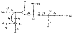
제4도는 본 발명의 실시예에 따른 알.에프.(RF) 자동이득제어기의 회로를 도시하는 회로이다.4 is a circuit diagram showing a circuit of an RF automatic gain controller according to an embodiment of the present invention.
제5도는 본 발명의 실시예에 따른 알.에프.(RF) 자동이득제어기의 동작에 의한 알.에프(RF)감쇄량을 도시한 그래프이다.5 is a graph showing the amount of RF attenuation due to the operation of the RF automatic gain controller according to an embodiment of the present invention.
제6도는 본 발명의 다른 실시예에 따른 알.에프.(RF) 자동이득제어기의 회로를 도시하는 회로도이다.6 is a circuit diagram showing a circuit of an RF gain controller according to another embodiment of the present invention.
제7도는 본 발명의 다른 실시예에 따른 알.에프.(RF) 자동이득제어기의 동작에 의한 알.에프.(RF) 감쇄량을 도시한 그래프이다.7 is a graph showing the amount of RF attenuation due to the operation of the RF gain controller according to another embodiment of the present invention.
* 도면의 주요부분에 대한 부호의 설명* Explanation of symbols for main parts of the drawings
41 : 제1입력단 42 : 제2입력단41: first input terminal 42: second input terminal
43 : 출력단 44 : 중계점43: output stage 44: relay point
45 : 제어단 Q1 : 트랜지스터45: control stage Q1: transistor
C1,C2 : 직류전류 차단용 커패시터 D1,D2 : 핀다이오우드C1, C2: DC current blocking capacitor D1, D2: Pin diode
D3 : 스위칭용 다이오우드D3: Switching diode
본 발명은 상기와 같은 목적을 이루기 위한 본 발명은.The present invention for achieving the above object.
베이스단과 에미터단 및 콜렉터단을 구비하는 트랜지스터와, 자동이득제어검파기에서 출력되는 자동이득제어기전압이 인가되는 제1입력단과, 튜너의 제1알.에프.(RF)앰프의 출력이 인가되는 제2입력단과, 알.에프.(RF)자동이득제어기의 출력신호를 튜너의 제2알.에프.(RF)앰프의 입력으로 인가하는 출력단과, 베이스단과 제1입력단 사이에 연결된 제1저항과, 에미터단과 제2입력단의 사이에 연결되는 제4저항 및, 제2입력단과 출력단의 사이에 연결되는 자동이득제어기용 핀다이오우드를 구비하는 알.에프.(RF)자동이득제어기에 있어서.A transistor including a base stage, an emitter stage, and a collector stage, a first input terminal to which an automatic gain controller voltage output from the automatic gain control detector is applied, and a first to which an output of the first RF amplifier of the tuner is applied. 2 an input terminal, an output terminal for applying the output signal of the RF gain controller to the input of the tuner's second RF amplifier, and a first resistor connected between the base terminal and the first input terminal. And a fourth resistor connected between the emitter stage and the second input stage, and a pin diode for the automatic gain controller coupled between the second input stage and the output stage.
중계점과, 제어전압을 인가하는 제어단과, 중계점과 제어단이 사이에 연결되는 제2저항과, 중계점과 베이스단 사이에 연결되는 스위칭용 다이오우드와, 중계점과 접지 사이에 연결되는 제3저항을 구비하는 것을 특징으로 한다.A relay point, a control terminal for applying a control voltage, a second resistor connected between the relay point and the control terminal, a switching diode connected between the relay point and the base end, and a terminal connected between the relay point and ground. It is characterized by including three resistors.
이하, 본 발명의 실시예의 구성 및 작용을 첨부된 도면을 참조하여 보다 상세하게 설명하면 다음과 같다.Hereinafter, the configuration and operation of the embodiment of the present invention will be described in detail with reference to the accompanying drawings.
제4도는 본 발명의 실시예에 따른 알.에프.(RF)자동이득제어기의 회로를 도시 하는 회로로서, 여기에서 도시한 바와 같이 본 발명의 실시예에 따른 알.에프(RF)자동이득제어기는, 베어스단과 에미터단 및 콜렉터단을 구비하는 트랜지스터(Q1)와, 자동이득제어기검파기에서 출력되는 자동이득제어전압이 인가되는 제1입력단(41)과, 튜너의 제1알.에프.(RF)엠프의 출력이 직류전류 차단용 제1커패시터(C1)를 통하여 인가되는 제2입력단(42)과, 직류전류 차단용 제2커패시터(C2)를 통하여 알.에프.(RF)자동이득제어기의 출력신호를 튜너의 제2알.에프.(RF)의 입력으로 인가하는 출력단(43)과, 베이스단과 제1입력단 사이에 연결된 제1저항(R1)과, 에미터단과 제2입력단(42)의 사이에 연결되는 제4저항(R4) 및, 제2입력단(42)에 양(+)극이 연결되고 출력단(43)에 음(-)극이 연결되는 자동이득제어용 핀다이오우드 (D1,D2)와, 중계점(44)과, 제어전압을 인가하는 제어단(45)과, 중계점(44)과 제어단(45)의 사이에 연결되는 제2저항(R2)과, 중계점에 양(+)극이 연결되고 베이스단에 음(-)극이 연결되는 스위칭용 다이오우드(D3)와, 중계점(44)과 접지 사이에 연결되는 제3저항(R3)을 구비하고 있다. 여기서 L은 자동이득제어기의 전류패스용 인턱터이다.4 is a circuit diagram showing a circuit of an R. F. automatic gain controller according to an embodiment of the present invention, and as shown here, an R. F. automatic gain controller according to an embodiment of the present invention. Is a transistor (Q1) having a bearer stage, an emitter stage, and a collector stage, a first input terminal (41) to which an automatic gain control voltage output from an automatic gain controller detector is applied, and a first R.F. Of the RF automatic gain controller through the
스위칭용 다이오우드(D1)는 자동이득제어전압(VAGC)과 제어전압(VC)에 의해 온 또는 오프 될 수 있다. 제어전압(VC)으로 5V가 가해지고 R2=R3라 하면, 중계점에서의 전압은 2.5V가된다. 그러면 스위칭용 다이오우드(D1)는 자동이득제어전압(VAGC)이 1.8V이하이면 온 되는데 다이오우드(D1)가 온이 된다면 자동이득제어기의 특성곡선이 바뀐다. 제5도는 본 발명의 실시예에 따른 알.에프.(RF)자동이득제어기의 동작에 따른 알.에프.(RF)감쇄량을 도시한 그래프이다. 즉 자동이득제어전압(VAGC)이 1.8V 이상인 약전계에서는 다이오우드가 오프되어서 (a)의 곡선을 따라 가다가 자동이득제어전압(VAGC)이 1.8V이하의 강전계가 되면 다이오우드가 온 되어 자동이득제어기의 특성곡선은 (a)에서 (b)로 바뀌어 감쇄가 커진다. 약전계에서는 (a)의 곡선이므로 알.에프.(RF)의 감쇄가 적으므로 믹서로 입력되는 알.에프.(RF)신호가 커져서 좋은 에스.엔.(S/N)비를 얻을 수 있고 강전계에서는 (b)의 곡선으로 동작하므로 감쇄를 많이 시켜서 포화를 방지하고 좋은 비트 특성을 얻을 수 있다. 이 기준이 되는 1.8V의 전압은 제어전압(VC)을 조정하거나 R2와 R3를 조절함으로써 얼마든지 바꿀 수 있다The switching diode D1 may be turned on or off by the automatic gain control voltage VAGC and the control voltage VC. When 5V is applied to the control voltage VC and R2 = R3, the voltage at the relay point is 2.5V. Then, the switching diode D1 is turned on when the automatic gain control voltage V AGC is 1.8 V or less. When the diode D1 is turned on, the characteristic curve of the automatic gain controller is changed. 5 is a graph showing the amount of RF attenuation according to the operation of the RF gain controller according to the embodiment of the present invention. That is, in the weak field with automatic gain control voltage (V AGC ) of 1.8V or higher, the diode is turned off to follow the curve of (a), and when the automatic gain control voltage (V AGC ) becomes a strong field with 1.8V or less, the diode is turned on and the automatic gain is achieved. The characteristic curve of the controller changes from (a) to (b) so that the attenuation becomes large. In the weak electric field, since the curve of (a) is small, the attenuation of R.F. (RF) is small, so that the S.N. (S / N) ratio can be obtained because the R.F. (RF) signal input to the mixer is increased. In the strong electric field, it operates in the curve of (b), so that the attenuation is increased a lot to prevent saturation and to obtain good bit characteristics. This reference 1.8V voltage can be changed by adjusting the control voltage (V C ) or by adjusting R2 and R3.
첨부된 도면을 참조하여 본 발명의 다른 실시예의 구성 및 동작을 설명하면 다음과 같다.Referring to the configuration and operation of the other embodiment of the present invention with reference to the accompanying drawings as follows.
제6도는 본 발명의 다른 실시예에 따른 알.에프.(RF)자동이득제어기의 회로를 도시하는 회로도로서 여기에서 도시한 바와 같이 앞에서의 실시예와 다른점은 트랜지스터(Q1)의 베이스단과 중계점의 사이에 연결된 다이오우드(D3)에 제5저항(R5)이 병렬로 연결되어 있다는 것이다. 이렇게 다이오우드(D1)에 저항(R5)을 벙렬로 연결하므로써 자동이득제어기의 특성곡선을 완만하게 스위칭하도록 한다. 제7도는 본 발명의 다른 실시예에 따른 알.에프.(RF)자동이득제어기의 동작에 따른 알.에프.(RF)감쇄량을 도시한 그래프로서 여기에서 바와 같이 곡선이 제5도에서 도시한 곡선(a)와 (b)를 따르되 스위칭되는 시점에서 완만하게 변화하고 있다. 이 때 병렬로 연결된 저항(R5)의 크기를 조정함으로써 곡선의 커브가 더욱 완만하게 변화할 수 있으며 또한 다이오우드(D3)가 핀다이오우드라면 그 저항의 변화 슬로프가 상대적으로 완만하므로 자동이득제어기의 특성곡선을 완만하게 조절할 수 있다.FIG. 6 is a circuit diagram showing a circuit of an RF gain controller according to another embodiment of the present invention. As shown here, FIG. 6 differs from the previous embodiment in that the base stage and the relay of the transistor Q1 are shown. The fifth resistor R5 is connected in parallel to the diode D3 connected between the dots. In this way, by connecting the resistor (R5) in parallel to the diode (D1) to smoothly switch the characteristic curve of the automatic gain controller. FIG. 7 is a graph showing the amount of RF attenuation according to the operation of the RF gain controller according to another embodiment of the present invention. Following curves (a) and (b), they change slowly at the point of switching. At this time, by adjusting the size of the resistor R5 connected in parallel, the curve of the curve can be changed more smoothly. Also, if the diode D3 is a pin diode, the slope of the resistance change is relatively gentle, so the characteristic curve of the automatic gain controller Can be adjusted gently.
이와 같이 본 발명은 자동이득제어기의 특성곡선을 특정전계에서 스위칭하게 만들므로써 강전계에서는 충분한 감쇄(reduction)를 주어 포화(saturation)를 방지면서 약전계에서는 감쇄를 적게하여 이득제어기가 동작할 때 강전계에서 좋은 비트 특성을 얻을 수 있을 뿐만 아니라 약전계에서는 에스.엔.(S/N)비를 좋게 하도록 하는 2가지의 상반된 효과를 모두 얻을 수 있다.As such, the present invention causes the characteristic curve of the automatic gain controller to be switched in a specific electric field, thereby giving sufficient reduction in the strong electric field to prevent saturation while reducing the attenuation in the weak electric field. Not only can we get good beat characteristics in the system, but we can also obtain two opposite effects in the weak electric field to improve the S / N ratio.
Claims (6)
Priority Applications (1)
| Application Number | Priority Date | Filing Date | Title |
|---|---|---|---|
| KR1019970026780A KR100254882B1 (en) | 1997-06-24 | 1997-06-24 | Rf-auto gain controller for improving the s/n ratio |
Applications Claiming Priority (1)
| Application Number | Priority Date | Filing Date | Title |
|---|---|---|---|
| KR1019970026780A KR100254882B1 (en) | 1997-06-24 | 1997-06-24 | Rf-auto gain controller for improving the s/n ratio |
Publications (2)
| Publication Number | Publication Date |
|---|---|
| KR19990003010A KR19990003010A (en) | 1999-01-15 |
| KR100254882B1 true KR100254882B1 (en) | 2000-05-01 |
Family
ID=19510901
Family Applications (1)
| Application Number | Title | Priority Date | Filing Date |
|---|---|---|---|
| KR1019970026780A Expired - Fee Related KR100254882B1 (en) | 1997-06-24 | 1997-06-24 | Rf-auto gain controller for improving the s/n ratio |
Country Status (1)
| Country | Link |
|---|---|
| KR (1) | KR100254882B1 (en) |
-
1997
- 1997-06-24 KR KR1019970026780A patent/KR100254882B1/en not_active Expired - Fee Related
Also Published As
| Publication number | Publication date |
|---|---|
| KR19990003010A (en) | 1999-01-15 |
Similar Documents
| Publication | Publication Date | Title |
|---|---|---|
| US6288609B1 (en) | Gain controllable low noise amplifier with automatic linearity enhancement and method of doing same | |
| US5175883A (en) | Receiving apparatus | |
| US5994963A (en) | Amplifier circuit and multistage amplifier circuit | |
| CN1098568C (en) | Improvements in or relating to radio receivers | |
| US7548116B2 (en) | High-frequency circuit of reduced circuit scale | |
| KR100254882B1 (en) | Rf-auto gain controller for improving the s/n ratio | |
| KR910000694B1 (en) | High frequency amplifier | |
| US7345556B2 (en) | Variable attenuation circuit having large attenuation amount with small circuit size | |
| KR850000733B1 (en) | Variable Emitter Attenuation Gain Control Amplifier | |
| KR100254881B1 (en) | 2 input-type rf-auto gain controller | |
| JP3795282B2 (en) | Transmission path switching circuit | |
| KR100190610B1 (en) | Automatic gain control circuit | |
| US6977555B2 (en) | Tuner circuit | |
| US6472938B2 (en) | Automatic level controlling circuit | |
| KR960005374B1 (en) | High frequency amplification device | |
| JP2000041199A (en) | Video intermediate frequency amplifier | |
| KR19990058812A (en) | Automatic level control device | |
| KR20060013554A (en) | Channel selector with automatic gain control | |
| JPH0897651A (en) | Automatic gain control circuit | |
| JPH0687532B2 (en) | Automatic gain control circuit | |
| JP3082922B2 (en) | Radio receiver | |
| JPH0718192Y2 (en) | TV tuner | |
| KR20000018301A (en) | Device and a method thereof for receiving efficiency and a high dynamic range in a mobile communications terminal device | |
| JP2506719B2 (en) | High frequency amplifier | |
| KR800001064Y1 (en) | Automatic Gain Control Circuit (AGC) |
Legal Events
| Date | Code | Title | Description |
|---|---|---|---|
| PA0109 | Patent application |
St.27 status event code: A-0-1-A10-A12-nap-PA0109 |
|
| R17-X000 | Change to representative recorded |
St.27 status event code: A-3-3-R10-R17-oth-X000 |
|
| A201 | Request for examination | ||
| PA0201 | Request for examination |
St.27 status event code: A-1-2-D10-D11-exm-PA0201 |
|
| R18-X000 | Changes to party contact information recorded |
St.27 status event code: A-3-3-R10-R18-oth-X000 |
|
| PG1501 | Laying open of application |
St.27 status event code: A-1-1-Q10-Q12-nap-PG1501 |
|
| E701 | Decision to grant or registration of patent right | ||
| PE0701 | Decision of registration |
St.27 status event code: A-1-2-D10-D22-exm-PE0701 |
|
| GRNT | Written decision to grant | ||
| PR0701 | Registration of establishment |
St.27 status event code: A-2-4-F10-F11-exm-PR0701 |
|
| PR1002 | Payment of registration fee |
St.27 status event code: A-2-2-U10-U11-oth-PR1002 Fee payment year number: 1 |
|
| PG1601 | Publication of registration |
St.27 status event code: A-4-4-Q10-Q13-nap-PG1601 |
|
| PR1001 | Payment of annual fee |
St.27 status event code: A-4-4-U10-U11-oth-PR1001 Fee payment year number: 4 |
|
| PR1001 | Payment of annual fee |
St.27 status event code: A-4-4-U10-U11-oth-PR1001 Fee payment year number: 5 |
|
| PR1001 | Payment of annual fee |
St.27 status event code: A-4-4-U10-U11-oth-PR1001 Fee payment year number: 6 |
|
| R18-X000 | Changes to party contact information recorded |
St.27 status event code: A-5-5-R10-R18-oth-X000 |
|
| PR1001 | Payment of annual fee |
St.27 status event code: A-4-4-U10-U11-oth-PR1001 Fee payment year number: 7 |
|
| PR1001 | Payment of annual fee |
St.27 status event code: A-4-4-U10-U11-oth-PR1001 Fee payment year number: 8 |
|
| R18-X000 | Changes to party contact information recorded |
St.27 status event code: A-5-5-R10-R18-oth-X000 |
|
| PR1001 | Payment of annual fee |
St.27 status event code: A-4-4-U10-U11-oth-PR1001 Fee payment year number: 9 |
|
| PR1001 | Payment of annual fee |
St.27 status event code: A-4-4-U10-U11-oth-PR1001 Fee payment year number: 10 |
|
| PR1001 | Payment of annual fee |
St.27 status event code: A-4-4-U10-U11-oth-PR1001 Fee payment year number: 11 |
|
| PR1001 | Payment of annual fee |
St.27 status event code: A-4-4-U10-U11-oth-PR1001 Fee payment year number: 12 |
|
| PR1001 | Payment of annual fee |
St.27 status event code: A-4-4-U10-U11-oth-PR1001 Fee payment year number: 13 |
|
| FPAY | Annual fee payment |
Payment date: 20130111 Year of fee payment: 14 |
|
| PR1001 | Payment of annual fee |
St.27 status event code: A-4-4-U10-U11-oth-PR1001 Fee payment year number: 14 |
|
| FPAY | Annual fee payment |
Payment date: 20131224 Year of fee payment: 15 |
|
| PR1001 | Payment of annual fee |
St.27 status event code: A-4-4-U10-U11-oth-PR1001 Fee payment year number: 15 |
|
| R18-X000 | Changes to party contact information recorded |
St.27 status event code: A-5-5-R10-R18-oth-X000 |
|
| LAPS | Lapse due to unpaid annual fee | ||
| PC1903 | Unpaid annual fee |
St.27 status event code: A-4-4-U10-U13-oth-PC1903 Not in force date: 20150209 Payment event data comment text: Termination Category : DEFAULT_OF_REGISTRATION_FEE |
|
| PC1903 | Unpaid annual fee |
St.27 status event code: N-4-6-H10-H13-oth-PC1903 Ip right cessation event data comment text: Termination Category : DEFAULT_OF_REGISTRATION_FEE Not in force date: 20150209 |
|
| P22-X000 | Classification modified |
St.27 status event code: A-4-4-P10-P22-nap-X000 |
|
| R18-X000 | Changes to party contact information recorded |
St.27 status event code: A-5-5-R10-R18-oth-X000 |