JPWO2020149120A1 - Input device and operation unit - Google Patents
Input device and operation unit Download PDFInfo
- Publication number
- JPWO2020149120A1 JPWO2020149120A1 JP2020566176A JP2020566176A JPWO2020149120A1 JP WO2020149120 A1 JPWO2020149120 A1 JP WO2020149120A1 JP 2020566176 A JP2020566176 A JP 2020566176A JP 2020566176 A JP2020566176 A JP 2020566176A JP WO2020149120 A1 JPWO2020149120 A1 JP WO2020149120A1
- Authority
- JP
- Japan
- Prior art keywords
- signal
- operation unit
- movable member
- input device
- knob
- Prior art date
- Legal status (The legal status is an assumption and is not a legal conclusion. Google has not performed a legal analysis and makes no representation as to the accuracy of the status listed.)
- Granted
Links
Images


Classifications
-
- G—PHYSICS
- G06—COMPUTING OR CALCULATING; COUNTING
- G06F—ELECTRIC DIGITAL DATA PROCESSING
- G06F3/00—Input arrangements for transferring data to be processed into a form capable of being handled by the computer; Output arrangements for transferring data from processing unit to output unit, e.g. interface arrangements
- G06F3/01—Input arrangements or combined input and output arrangements for interaction between user and computer
- G06F3/03—Arrangements for converting the position or the displacement of a member into a coded form
- G06F3/033—Pointing devices displaced or positioned by the user, e.g. mice, trackballs, pens or joysticks; Accessories therefor
- G06F3/0338—Pointing devices displaced or positioned by the user, e.g. mice, trackballs, pens or joysticks; Accessories therefor with detection of limited linear or angular displacement of an operating part of the device from a neutral position, e.g. isotonic or isometric joysticks
-
- B—PERFORMING OPERATIONS; TRANSPORTING
- B60—VEHICLES IN GENERAL
- B60K—ARRANGEMENT OR MOUNTING OF PROPULSION UNITS OR OF TRANSMISSIONS IN VEHICLES; ARRANGEMENT OR MOUNTING OF PLURAL DIVERSE PRIME-MOVERS IN VEHICLES; AUXILIARY DRIVES FOR VEHICLES; INSTRUMENTATION OR DASHBOARDS FOR VEHICLES; ARRANGEMENTS IN CONNECTION WITH COOLING, AIR INTAKE, GAS EXHAUST OR FUEL SUPPLY OF PROPULSION UNITS IN VEHICLES
- B60K35/00—Instruments specially adapted for vehicles; Arrangement of instruments in or on vehicles
- B60K35/10—Input arrangements, i.e. from user to vehicle, associated with vehicle functions or specially adapted therefor
-
- B—PERFORMING OPERATIONS; TRANSPORTING
- B60—VEHICLES IN GENERAL
- B60K—ARRANGEMENT OR MOUNTING OF PROPULSION UNITS OR OF TRANSMISSIONS IN VEHICLES; ARRANGEMENT OR MOUNTING OF PLURAL DIVERSE PRIME-MOVERS IN VEHICLES; AUXILIARY DRIVES FOR VEHICLES; INSTRUMENTATION OR DASHBOARDS FOR VEHICLES; ARRANGEMENTS IN CONNECTION WITH COOLING, AIR INTAKE, GAS EXHAUST OR FUEL SUPPLY OF PROPULSION UNITS IN VEHICLES
- B60K35/00—Instruments specially adapted for vehicles; Arrangement of instruments in or on vehicles
- B60K35/60—Instruments characterised by their location or relative disposition in or on vehicles
-
- G—PHYSICS
- G06—COMPUTING OR CALCULATING; COUNTING
- G06F—ELECTRIC DIGITAL DATA PROCESSING
- G06F3/00—Input arrangements for transferring data to be processed into a form capable of being handled by the computer; Output arrangements for transferring data from processing unit to output unit, e.g. interface arrangements
- G06F3/01—Input arrangements or combined input and output arrangements for interaction between user and computer
- G06F3/03—Arrangements for converting the position or the displacement of a member into a coded form
- G06F3/033—Pointing devices displaced or positioned by the user, e.g. mice, trackballs, pens or joysticks; Accessories therefor
- G06F3/0362—Pointing devices displaced or positioned by the user, e.g. mice, trackballs, pens or joysticks; Accessories therefor with detection of one-dimensional [1D] translations or rotations of an operating part of the device, e.g. scroll wheels, sliders, knobs, rollers or belts
-
- H—ELECTRICITY
- H01—ELECTRIC ELEMENTS
- H01H—ELECTRIC SWITCHES; RELAYS; SELECTORS; EMERGENCY PROTECTIVE DEVICES
- H01H21/00—Switches operated by an operating part in the form of a pivotable member acted upon directly by a solid body, e.g. by a hand
- H01H21/02—Details
- H01H21/04—Cases; Covers
-
- H—ELECTRICITY
- H01—ELECTRIC ELEMENTS
- H01H—ELECTRIC SWITCHES; RELAYS; SELECTORS; EMERGENCY PROTECTIVE DEVICES
- H01H21/00—Switches operated by an operating part in the form of a pivotable member acted upon directly by a solid body, e.g. by a hand
- H01H21/02—Details
- H01H21/04—Cases; Covers
- H01H21/06—Cases; Covers interlocked with operating mechanism
-
- H—ELECTRICITY
- H01—ELECTRIC ELEMENTS
- H01H—ELECTRIC SWITCHES; RELAYS; SELECTORS; EMERGENCY PROTECTIVE DEVICES
- H01H21/00—Switches operated by an operating part in the form of a pivotable member acted upon directly by a solid body, e.g. by a hand
- H01H21/02—Details
- H01H21/18—Movable parts; Contacts mounted thereon
- H01H21/22—Operating parts, e.g. handle
- H01H21/24—Operating parts, e.g. handle biased to return to normal position upon removal of operating force
-
- H—ELECTRICITY
- H01—ELECTRIC ELEMENTS
- H01H—ELECTRIC SWITCHES; RELAYS; SELECTORS; EMERGENCY PROTECTIVE DEVICES
- H01H21/00—Switches operated by an operating part in the form of a pivotable member acted upon directly by a solid body, e.g. by a hand
- H01H21/02—Details
- H01H21/18—Movable parts; Contacts mounted thereon
- H01H21/36—Driving mechanisms
- H01H21/40—Driving mechanisms having snap action
-
- B—PERFORMING OPERATIONS; TRANSPORTING
- B60—VEHICLES IN GENERAL
- B60K—ARRANGEMENT OR MOUNTING OF PROPULSION UNITS OR OF TRANSMISSIONS IN VEHICLES; ARRANGEMENT OR MOUNTING OF PLURAL DIVERSE PRIME-MOVERS IN VEHICLES; AUXILIARY DRIVES FOR VEHICLES; INSTRUMENTATION OR DASHBOARDS FOR VEHICLES; ARRANGEMENTS IN CONNECTION WITH COOLING, AIR INTAKE, GAS EXHAUST OR FUEL SUPPLY OF PROPULSION UNITS IN VEHICLES
- B60K2360/00—Indexing scheme associated with groups B60K35/00 or B60K37/00 relating to details of instruments or dashboards
- B60K2360/128—Axially displaceable input devices for instruments
-
- B—PERFORMING OPERATIONS; TRANSPORTING
- B60—VEHICLES IN GENERAL
- B60K—ARRANGEMENT OR MOUNTING OF PROPULSION UNITS OR OF TRANSMISSIONS IN VEHICLES; ARRANGEMENT OR MOUNTING OF PLURAL DIVERSE PRIME-MOVERS IN VEHICLES; AUXILIARY DRIVES FOR VEHICLES; INSTRUMENTATION OR DASHBOARDS FOR VEHICLES; ARRANGEMENTS IN CONNECTION WITH COOLING, AIR INTAKE, GAS EXHAUST OR FUEL SUPPLY OF PROPULSION UNITS IN VEHICLES
- B60K2360/00—Indexing scheme associated with groups B60K35/00 or B60K37/00 relating to details of instruments or dashboards
- B60K2360/40—Hardware adaptations for dashboards or instruments
- B60K2360/48—Sensors
-
- B—PERFORMING OPERATIONS; TRANSPORTING
- B60—VEHICLES IN GENERAL
- B60K—ARRANGEMENT OR MOUNTING OF PROPULSION UNITS OR OF TRANSMISSIONS IN VEHICLES; ARRANGEMENT OR MOUNTING OF PLURAL DIVERSE PRIME-MOVERS IN VEHICLES; AUXILIARY DRIVES FOR VEHICLES; INSTRUMENTATION OR DASHBOARDS FOR VEHICLES; ARRANGEMENTS IN CONNECTION WITH COOLING, AIR INTAKE, GAS EXHAUST OR FUEL SUPPLY OF PROPULSION UNITS IN VEHICLES
- B60K2360/00—Indexing scheme associated with groups B60K35/00 or B60K37/00 relating to details of instruments or dashboards
- B60K2360/60—Structural details of dashboards or instruments
- B60K2360/68—Features of instruments
- B60K2360/691—Housings
-
- B—PERFORMING OPERATIONS; TRANSPORTING
- B60—VEHICLES IN GENERAL
- B60K—ARRANGEMENT OR MOUNTING OF PROPULSION UNITS OR OF TRANSMISSIONS IN VEHICLES; ARRANGEMENT OR MOUNTING OF PLURAL DIVERSE PRIME-MOVERS IN VEHICLES; AUXILIARY DRIVES FOR VEHICLES; INSTRUMENTATION OR DASHBOARDS FOR VEHICLES; ARRANGEMENTS IN CONNECTION WITH COOLING, AIR INTAKE, GAS EXHAUST OR FUEL SUPPLY OF PROPULSION UNITS IN VEHICLES
- B60K2360/00—Indexing scheme associated with groups B60K35/00 or B60K37/00 relating to details of instruments or dashboards
- B60K2360/77—Instrument locations other than the dashboard
- B60K2360/791—Instrument locations other than the dashboard on or in the transmission tunnel or parking brake lever
-
- B—PERFORMING OPERATIONS; TRANSPORTING
- B60—VEHICLES IN GENERAL
- B60K—ARRANGEMENT OR MOUNTING OF PROPULSION UNITS OR OF TRANSMISSIONS IN VEHICLES; ARRANGEMENT OR MOUNTING OF PLURAL DIVERSE PRIME-MOVERS IN VEHICLES; AUXILIARY DRIVES FOR VEHICLES; INSTRUMENTATION OR DASHBOARDS FOR VEHICLES; ARRANGEMENTS IN CONNECTION WITH COOLING, AIR INTAKE, GAS EXHAUST OR FUEL SUPPLY OF PROPULSION UNITS IN VEHICLES
- B60K2360/00—Indexing scheme associated with groups B60K35/00 or B60K37/00 relating to details of instruments or dashboards
- B60K2360/92—Manufacturing of instruments
-
- B—PERFORMING OPERATIONS; TRANSPORTING
- B60—VEHICLES IN GENERAL
- B60K—ARRANGEMENT OR MOUNTING OF PROPULSION UNITS OR OF TRANSMISSIONS IN VEHICLES; ARRANGEMENT OR MOUNTING OF PLURAL DIVERSE PRIME-MOVERS IN VEHICLES; AUXILIARY DRIVES FOR VEHICLES; INSTRUMENTATION OR DASHBOARDS FOR VEHICLES; ARRANGEMENTS IN CONNECTION WITH COOLING, AIR INTAKE, GAS EXHAUST OR FUEL SUPPLY OF PROPULSION UNITS IN VEHICLES
- B60K35/00—Instruments specially adapted for vehicles; Arrangement of instruments in or on vehicles
- B60K35/20—Output arrangements, i.e. from vehicle to user, associated with vehicle functions or specially adapted therefor
- B60K35/21—Output arrangements, i.e. from vehicle to user, associated with vehicle functions or specially adapted therefor using visual output, e.g. blinking lights or matrix displays
- B60K35/22—Display screens
-
- B—PERFORMING OPERATIONS; TRANSPORTING
- B60—VEHICLES IN GENERAL
- B60K—ARRANGEMENT OR MOUNTING OF PROPULSION UNITS OR OF TRANSMISSIONS IN VEHICLES; ARRANGEMENT OR MOUNTING OF PLURAL DIVERSE PRIME-MOVERS IN VEHICLES; AUXILIARY DRIVES FOR VEHICLES; INSTRUMENTATION OR DASHBOARDS FOR VEHICLES; ARRANGEMENTS IN CONNECTION WITH COOLING, AIR INTAKE, GAS EXHAUST OR FUEL SUPPLY OF PROPULSION UNITS IN VEHICLES
- B60K37/00—Dashboards
- B60K37/20—Dashboard panels
Landscapes
- Engineering & Computer Science (AREA)
- Chemical & Material Sciences (AREA)
- Combustion & Propulsion (AREA)
- Transportation (AREA)
- Mechanical Engineering (AREA)
- General Engineering & Computer Science (AREA)
- Theoretical Computer Science (AREA)
- Human Computer Interaction (AREA)
- Physics & Mathematics (AREA)
- General Physics & Mathematics (AREA)
- Switches With Compound Operations (AREA)
- Position Input By Displaying (AREA)
Abstract
【課題】操作方向と、操作量に応じたオン/オフの状態とを表す信号を出力する入力装置、及び、操作ユニットを提供する。【解決手段】入力装置は、操作部と、前記操作部に固定され、回転軸を有する可動部材と、前記可動部材が回動可能になるように前記回転軸を軸支する固定部材と、前記操作部に配置され、前記操作部の撓みを検出する撓みセンサと、前記可動部材又は前記固定部材に配置され、前記可動部材の回動動作によって押圧され、前記操作部の撓み量が所定量に達するとオン又はオフ状態が切り替えられるスイッチと、前記撓みセンサの第1出力信号と、前記スイッチの第2出力信号とに基づく制御信号を出力する信号処理部とを含む。PROBLEM TO BE SOLVED: To provide an input device for outputting a signal indicating an operation direction and an on / off state according to an operation amount, and an operation unit. An input device includes an operation unit, a movable member fixed to the operation unit and having a rotation shaft, and a fixing member that pivotally supports the rotation shaft so that the movable member can rotate. A deflection sensor arranged in the operation unit and detecting the deflection of the operation unit, and a deflection sensor arranged in the movable member or the fixing member and pressed by the rotational operation of the movable member, the amount of deflection of the operation unit becomes a predetermined amount. It includes a switch that is switched on or off when it reaches, and a signal processing unit that outputs a control signal based on the first output signal of the deflection sensor and the second output signal of the switch.
Description
本発明は、入力装置、及び、操作ユニットに関する。 The present invention relates to an input device and an operation unit.
従来より、二対の歪み検出素子を備え中央に固定部を有する弾性板を、固定部を中心とする円周上に配された弾性部材を介して平板状操作体で押すように構成される荷重センサとすることにより、平板状操作体の押す位置および移動量の大きさで出力信号の方向および大きさを調整することができる低寸法の荷重センサがある(例えば、特許文献1参照)。 Conventionally, an elastic plate having two pairs of strain detecting elements and a fixed portion in the center is pushed by a flat plate-shaped operating body via an elastic member arranged on the circumference centered on the fixed portion. There is a low-dimensional load sensor that can adjust the direction and magnitude of the output signal according to the pushing position and the amount of movement of the flat plate-shaped operating body by using the load sensor (see, for example, Patent Document 1).
ところで、従来の荷重センサは、操作方向に応じた方向を表す信号を出力するが、この信号以外の信号は出力しない。 By the way, the conventional load sensor outputs a signal indicating a direction corresponding to the operation direction, but does not output a signal other than this signal.
そこで、操作方向と、操作量に応じたオン/オフの状態とを表す信号を出力する入力装置、及び、操作ユニットを提供することを目的とする。 Therefore, it is an object of the present invention to provide an input device for outputting a signal indicating an operation direction and an on / off state according to an operation amount, and an operation unit.
本発明の実施の形態の入力装置は、操作部と、前記操作部に固定され、回転軸を有する可動部材と、前記可動部材が回動可能になるように前記回転軸を軸支する固定部材と、前記操作部に配置され、前記操作部の撓みを検出する撓みセンサと、前記可動部材又は前記固定部材に配置され、前記可動部材の回動動作によって押圧され、前記操作部の撓み量が所定量に達するとオン又はオフ状態が切り替えられるスイッチと、前記撓みセンサの第1出力信号と、前記スイッチの第2出力信号とに基づく制御信号を出力する信号処理部とを含む。 The input device according to the embodiment of the present invention includes an operation unit, a movable member fixed to the operation unit and having a rotation shaft, and a fixing member that pivotally supports the rotation shaft so that the movable member can rotate. A deflection sensor arranged in the operation unit to detect the deflection of the operation unit, and a deflection sensor arranged in the movable member or the fixing member and pressed by the rotational operation of the movable member, the amount of deflection of the operation unit is reduced. It includes a switch that can be switched on or off when a predetermined amount is reached, and a signal processing unit that outputs a control signal based on the first output signal of the deflection sensor and the second output signal of the switch.
操作方向と、操作量に応じたオン/オフの状態とを表す信号を出力する入力装置、及び、操作ユニットを提供することができる。 It is possible to provide an input device that outputs a signal indicating an operation direction and an on / off state according to an operation amount, and an operation unit.
以下、本発明の入力装置、及び、操作ユニットを適用した実施の形態について説明する。 Hereinafter, embodiments to which the input device and the operation unit of the present invention are applied will be described.
<実施の形態>
図1は、実施の形態の操作ユニット50を搭載した車両10の室内を示す図である。車両10は、運転席11、助手席12、センターコンソール13、アウターミラー14、インナーミラー15、ディスプレイ16を含む。車両10の室内に配置されるセンターコンソール13の運転席11と助手席12の間の部分には、操作ユニット50が設けられている。操作ユニット50は、本体部51とノブ52を含む。<Embodiment>
FIG. 1 is a diagram showing the interior of a
操作ユニット50は、車両10の種々の装置を操作するために設けられており、一例としてアウターミラー14やインナーミラー15の調整に用いることができる。利用者が手でノブ52を上下方向及び左右方向に撓ませると、アウターミラー14やインナーミラー15を上下方向及び左右方向に調整することができる。
The
図2は、実施の形態の入力装置100を示す図である。入力装置100は、図1の操作ユニット50に収容されている。入力装置100は、主な構成要素として、筐体110、レバー120、ノブ130、撓みセンサ140、プッシュスイッチ150A、150B、基板151A、151B、ホルダ152A、152B、ピン153A、153Bを含む。図2では、筐体110の一部(壁部110B)を透過的に示す。
FIG. 2 is a diagram showing an
以下では、XYZ座標系を定義して説明する。また、以下では、説明の便宜上、Z軸負方向側を下側又は下、Z軸正方向側を上側又は上と称すが、普遍的な上下関係を表すものではない。なお、図1に示す車両10の前方向は−Y方向、後ろ方向は+Y方向、左方向は+X方向、右方向が−X方向、上方向は+Z方向、下方向は−Z方向である。
In the following, the XYZ coordinate system will be defined and described. In the following, for convenience of explanation, the negative side of the Z axis is referred to as the lower side or the lower side, and the positive side of the Z axis is referred to as the upper side or the upper side, but does not represent a universal hierarchical relationship. The front direction of the
また、以下では、図2に加えて図3乃至図5を用いて説明を行う。図3は、実施の形態の入力装置100を示す分解図であり、図4は、実施の形態の入力装置100を示す上面図であり、図5は、実施の形態の入力装置100を示す側面図である。
Further, in the following, the description will be given with reference to FIGS. 3 to 5 in addition to FIG. FIG. 3 is an exploded view showing the
筐体110は、本体部110Aと壁部110Bを有する。筐体110は、一例として樹脂製である。本体部110Aは、略直方体状であり、上部がY軸方向に絞られた形状を有し、レバー120を収納する収納部110A1を有する。筐体110は、固定部材の一例である。筐体110は、図1の操作ユニット50の本体部51の内部に固定される。
The
本体部110Aは、+X方向側と+Z方向側が連続的に開口されており、収納部110A1を囲む下面側(−Z方向側)、−X方向側、及び±Y方向側の壁部を有する。また、本体部110は、軸受け部111A、固定部112A、ネジ穴113A、及び固定部114Aを有する。
The
軸受け部111Aは、−X方向側の壁部の+X方向側の面の上部に設けられており、レバー120の−X方向側の回転軸121Aを回動可能に軸支する。
The
固定部112Aは、−Y方向側の壁部の+Y方向側の面と、+Y方向側の壁部の−Y方向側の面とに設けられており、ネジ穴を有する。固定部112Aは、ホルダ152A、152Bをネジ留めするために設けられている。
The
ネジ穴113Aは、本体部110Aの+X方向側の開口部に面した壁部に3箇所設けられており、3本のネジ110Cによって壁部110Bが固定される。
Three
固定部114Aは、本体部110Aの高さ方向の中程で±X方向に突出する4つの突出部であり、Z軸方向に貫通する貫通孔を有する。固定部114Aは、一例として図1に示したように、車両10のセンターコンソール13に固定する際に、ネジやピンを挿通させるために設けられている。
The fixed
壁部110Bは、YZ面視で台形状の板状の部材であり、−X方向側の面に軸受け部111Aと同様の軸受け部を有する。
The
収納部110A1にレバー120を収納し、軸受け部111Aに−X方向側の回転軸121Aを挿入し、+X方向側の回転軸121Aを壁部110Bの軸受け部に挿入した状態で、本体部110Aと壁部110Bとをネジ110Cで固定することで、筐体110がレバー120を回動自在に保持する。
The
レバー120は、基部121と延在部122を有する。レバー120は、一例として樹脂製である。基部121は、X軸方向に延在する直方体状の部材であり、±X方向側の面から突出する回転軸121Aを有する。レバー120は、可動部材の一例である。
The
また、基部121の+Z方向側の面には、2つのネジ穴121Bが設けられている。ネジ穴121Bの平面視での中心は、2つの回転軸121Aの真上に位置する。ネジ穴121Bには、ネジ130Cによってノブ130が固定される。基部121の−Z方向側には延在部122が一体的に形成されている。
Further, two
+X方向側から見て、レバー120が回転軸121Aを中心に時計回り(図5における矢印A方向)に回動するとプッシュスイッチ150Aがピン153Aに当接する。レバー120が回転軸121Aを中心に反時計回り(図5における矢印B方向)に回動すると、プッシュスイッチ150Bがピン153Bに当接する。なお、時計回り及び反時計回りは、それぞれ、第1回動方向及び第2回動方向の一例である。
When the
ノブ130は、平面視で矩形状の薄い板状の部材であり、一例として樹脂製である。ノブ130は、操作部の一例である。ノブ130の下面側には、撓みセンサ140が設けられている。ノブ130は、入力装置100に入力操作を行う利用者が操作する部材である。ノブ130は、+Y方向側の+X方向側の端部側と、+Y方向側の−X方向側の端部側とに、ネジ孔131を有する。ネジ孔131の平面視での中心は、2つの回転軸121Aの真上に位置する。
The
また、ノブ130の−Y方向側の±X方向側の端部側の角は、平面視で曲線的に面取りされている。ノブ130は、ネジ孔131に挿通させたネジ130Cをレバー120のネジ穴121Bにネジ留めすることによって、レバー120の上端に固定される。このように、ノブ130は、レバー120が回転軸121Aから延在する方向(レバー120が回動していない状態におけるZ軸方向)において、回転軸121Aの+Z方向側に設けられる。回転軸121Aの+Z方向側は、第1側の一例である。
Further, the corner on the end side of the
ノブ130には、図1に示すノブ52が固定される。ノブ52は、ノブ130に嵌合、ネジ留め、接着等で固定され、ノブ130と一体的に動作する。
The knob 52 shown in FIG. 1 is fixed to the
ノブ130は、+Y方向側がレバー120にネジ留めされているため、レバー120と接触している部分よりも−Y方向側の部分は、利用者の手等で押圧されると撓むことによって変形する。ノブ130の操作は、利用者がノブ130のレバー120と接触している部分よりも−Y方向側の部分を左側(+X側)を上又は下に撓ませるように力を加えるか、又は、右側(−X側)を上又は下に撓ませるように力を加えることによって行われる。
Since the + Y direction side of the
なお、ノブ130の左側は、回転軸121Aの軸方向(X軸方向)における第1方向側であり、右側は第2方向側である。この場合に、第1方向は+X方向であり、第2方向は−X方向である。
The left side of the
このように、ノブ130に力を加える(押圧する)と、レバー120は、+X方向側から見て、回転軸121Aを中心に時計回り又は反時計回りに回動し、プッシュスイッチ150A又は150Bがピン153A又は153Bに当接する。
When a force is applied (pressed) to the
このときに、レバー120及びノブ130は梃子として動作する。支点は、回転軸121Aである。力点は、ノブ130に利用者の手等が触れる点である。作用点は、レバー120に基板151A、151Bを介して取り付けられるプッシュスイッチ150A、150Bが押圧される点である。プッシュスイッチ150A、150Bが押圧される点は、レバー120の回動動作によって直接的又は間接的にプッシュスイッチ150A、150Bを押圧する点であればよい。
At this time, the
このため、プッシュスイッチ150A、150Bが押圧される点は、レバー120に基板151A、151Bを介して取り付けられるプッシュスイッチ150A、150Bの表面にピン153A、153Bが当接する点であってもよい。プッシュスイッチ150A、150Bが押圧される点は、基板151A、151Bにプッシュスイッチ150A、150Bが実装される点であってもよい。また、プッシュスイッチ150A、150Bが押圧される点は、プッシュスイッチ150A又は150Bを実装する基板151A、151Bがレバー120に取り付けられている点であってもよい。
Therefore, the point where the push switches 150A and 150B are pressed may be the point where the
撓みセンサ140は、ノブ130に生じる撓みの方向を検出することにより、ノブ130への入力操作の方向を検出するために設けられている。撓みセンサ140は、図2及び図3では簡略化して示すが、具体的には図4に示すように、3つのセンサ部(センサ141、142、143)を有する。センサ141〜143は、平面視で細長いセンサ素子形状であり、長手方向における撓み(変形)を検出する。
The
図4に示すように、センサ143は、ノブ130のX軸方向の中央において、Y軸方向に延在する(長手方向がY軸に平行になる)ように配置されている。センサ141、142は、センサ143のX軸方向の幅の中心をY軸方向に通る中心線を対称軸として線対称に設けられている。
As shown in FIG. 4, the
回転軸121Aの中心軸を破線121A1で示す。センサ141、142の長手方向は、回転軸121Aの中心軸121A1に対して45度の角度をなし、センサ143の長手方向は、回転軸121Aの中心軸121A1に対して90度の角度をなす。すなわち、センサ141、143、142は、回転軸121Aの中心軸121A1に対して、45度、90度、135度の方向に沿ってそれぞれ延在している。
The central axis of the
プッシュスイッチ150A、150Bは、電気的なオン(導通)/オフ(非導通)の状態を切り替え可能なスイッチであり、3つずつ設けられている。プッシュスイッチ150A、150Bを3つずつ設けるのは、ノブ130の操作荷重を所望の荷重に調整するためである。なお、プッシュスイッチ150A及び150Bは、スイッチの一例である。
The push switches 150A and 150B are switches capable of switching between electrical on (conducting) and off (non-conducting) states, and are provided with three each. The reason why the push switches 150A and 150B are provided three by three is to adjust the operating load of the
プッシュスイッチ150A、150Bは、レバー120との位置関係では、レバー120が回転軸121Aから延在する方向(レバー120が回動していない状態におけるZ軸方向)において、回転軸121Aの−Z方向側に設けられる。回転軸121Aの−Z方向側は、第2側の一例である。
In the positional relationship with the
プッシュスイッチ150Aは、基板151Aの−Y方向側の面に3つ実装されている。基板151は、貫通孔151A1にネジ151A2を挿通させてレバー120の延在部122の−Y方向側の面にネジ留めされている。3つのプッシュスイッチ150Aは、同じ高さの位置においてX軸方向に配列されている。プッシュスイッチ150Aは、第1スイッチ部の一例である。
Three
プッシュスイッチ150Aは、バネを内蔵しており、所定の押圧力が掛かるとバネが開放されることによって、オフからオンに切り替わる。プッシュスイッチ150Aは、オンした状態で押圧され続けている間はオンの状態に保持され、押圧されなくなるとオフに切り替わるノーマリーオープン型のスイッチである。
The
なお、プッシュスイッチ150Aとしてノーマリーオープン型のスイッチに代えて、ノーマリークローズ型のスイッチを用いてもよい。その場合、押圧されている状態ではオフの状態に保持され、押圧されなくなると、オンに切り替わる。
As the
プッシュスイッチ150Aは、所定の押圧力が掛かるとバネが開放されてオフ状態からオン状態に切り替わり、プッシュスイッチ150Aを押圧した状態に保持するのに必要な押圧力が急激に低下する。このようなプッシュスイッチ150Aは、ノブ130を操作する利用者の手等にクリック感を提供する。
When a predetermined pressing force is applied to the
プッシュスイッチ150Bは、プッシュスイッチ150Aと同様に電気的なオン(導通)/オフ(非導通)の状態を切り替え可能なスイッチであり、基板151Bの+Y方向側の面に3つ実装されている。プッシュスイッチ150Bは、第2スイッチ部の一例である。
Similar to the
なお、プッシュスイッチ150Bは、プッシュスイッチ150Aと同様にノーマリーオープン型のスイッチであるが、ノーマリーオープン型のスイッチに代えて、ノーマリークローズ型のスイッチを用いてもよい。その場合、押圧されている状態ではオフの状態に保持され、押圧されなくなると、オンに切り替わる。
The
基板151Bは、貫通孔151B1にネジ151B2を挿通させてレバー120の延在部122の+Y方向側の面にネジ留めされている。3つのプッシュスイッチ150Bは、同じ高さの位置においてX軸方向に配列されている。プッシュスイッチ150Bは、プッシュスイッチ150Aと同様に、ノブ130を操作する利用者の手等にクリック感を提供する。
The
ホルダ152Aは、3本のピン153Aを挿通させて保持する部材であり、3つの貫通孔152A1にピン153Aが挿通された状態で固定される。貫通孔152A1へのピン153Aの固定は、嵌合又は接着等で行えばよい。
The
ホルダ152Aは、±Z方向に突出する突出部にX軸方向に貫通する貫通孔152A2を有し、貫通孔152A2に挿通させたネジ155を本体部110Aの固定部112Aにネジ留めすることによって、本体部110Aに固定される。
The
3本のピン153Aは、3つのプッシュスイッチ150Aと位置がそれぞれ合わされている。3本のピン153Aは、ノブ130が操作されてレバー120が図5に示す矢印Aの方向に回動すると、プッシュスイッチ150Aを押圧する。プッシュスイッチ150Aは、所定の押圧力が掛かるまではレバー120の回動を規制するバネ部材として作用する。
The three
ホルダ152Bは、3本のピン153Bを挿通させて保持する部材であり、3つの貫通孔152B1にピン153Bが挿通された状態で嵌着される。ホルダ152Bは、±Z方向に突出する突出部にX軸方向に貫通する貫通孔152B2を有する。ホルダ152Bは、貫通孔152B2に挿通させたネジ155を本体部110Aの固定部(固定部112Aと同様の固定部)にネジ留めすることによって、本体部110Aに固定される。
The
3本のピン153Bは、3つのプッシュスイッチ150Bと位置が合わされている。3本のピン153Bは、ノブ130が操作されてレバー120が図5に示す矢印Bの方向に回動すると、プッシュスイッチ150Bを押圧する。プッシュスイッチ150Bは、所定の押圧力が掛かるまではレバー120の回動を規制するバネ部材として作用する。
The three
図6は、ノブ130の撓み量に対する反力の特性を示す図である。ノブ130は、レバー120と接触している部分よりも−Y方向側が撓むことによって変形可能である。このように変形させるために利用者が手等で力を加えると、利用者の手等には反力が生じる。この反力は、ノブ130の操作荷重である。
FIG. 6 is a diagram showing the characteristics of the reaction force with respect to the amount of bending of the
ノブ130がZ軸方向に撓む量は、入力装置100におけるノブ130のストロークであり、一例としてノブ130の−Y方向側の端部におけるZ方向のストロークを示す。反力は、ノブ130から利用者の手等に作用する反力であり、ノブ130を操作することによってプッシュスイッチ150A、150Bを作動させるために必要な作動力である。
The amount of bending of the
ここで、ノブ130とプッシュスイッチ150A、150Bをバネとして扱い、バネ定数をkとする。ノブ130の撓み量Mが目標値M1に達したときに、反力Fは目標値F1になり、プッシュスイッチ150A、150Bのバネが開放されてクリック感を提供するように、ノブ130とプッシュスイッチ150A、150Bが設計されている。
Here, the
ここで、図5に示すように、XZ平面における回転軸121Aの中心からノブ130に操作が行われる位置(操作位置)までの距離をL1、回転軸121Aの中心からスイッチ150A、150Bの中心までの距離をL2、スイッチ150A、150Bのバネが開放するのに必要な押圧力をFsとすると、クリック感を提供する際の反力Fは以下の式(1)で表される。
F=L2/L1×Fs (1)Here, as shown in FIG. 5, the distance from the center of the
F = L2 / L1 × Fs (1)
また、このときの操作位置におけるノブ130の撓み量Mは、次式(2)で表される。
M=F/k=Fs/k×L2/L1 (2)Further, the amount of deflection M of the
M = F / k = Fs / k × L2 / L1 (2)
図6に示すように、ノブ130の撓み量Mが増大すると反力Fも増大し、撓み量Mが目標値M1に達すると、プッシュスイッチ150A、150Bのバネが開放されるため、反力が少し低下する。この時点で、プッシュスイッチ150A、150Bは、それ以上押圧できない状態(完全に押し潰された状態)になっている。このように、プッシュスイッチ150A、150Bのバネが開放されて反力が少し低下することで、ノブ130に触れている利用者の手等にクリック感が提供される。ノブ130の剛性とプッシュスイッチ150A、150Bの押圧力Fsを適切な値に設定することによって、所望のクリック感を提供することができる。
As shown in FIG. 6, when the bending amount M of the
ただし、この場合に、ノブ130の降伏応力以下の動作領域で実現できるようにノブ130の材料やサイズ(X軸、Y軸方向の長さ、Z軸方向の厚さ等)を設定する必要がある。
However, in this case, it is necessary to set the material and size (length in the X-axis and Y-axis directions, thickness in the Z-axis direction, etc.) of the
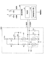
図7は、入力装置100の回路を示す図である。入力装置100は、センサ回路部140Aを含み、センサ回路部140Aにおいて、撓みセンサ140のセンサ141と142は、抵抗器R1とともに、電源Vccとグランドとの間に直列に接続されている。また、センサ143は、抵抗器R2及びR3とともに、電源Vccとグランドとの間に直列に接続されている。また、図7に示すようにコンデンサC1〜C4が設けられている。
FIG. 7 is a diagram showing a circuit of the
また、入力装置100は、信号処理部160を含む。信号処理部160は、マイクロコンピュータのような情報処理部と、A/D(Analog to Digital)変換器とを含む。図7には、信号処理部160の情報処理部によって実現される判定部161と制御信号出力部162を示す。判定部161と制御信号出力部162は、信号処理部160の情報処理部によって実現される機能ブロックを表したものである。
Further, the
信号処理部160には、センサ141と142の接続点の電圧値を表すL/R信号と、抵抗器R3とセンサ143との接続点の電圧値を表すU/D信号と、プッシュスイッチ150A、150Bのオン/オフの状態を表すA信号、B信号とが入力される。L/R信号及びU/D信号は、第1出力信号の一例である。
The
L/R信号は、ノブ130への入力操作が左(Left)方向又は右(Right)方向のどちらに行われているかを表す信号である。また、U/D信号は、ノブ130への入力操作が上(Up)方向又は下(Down)方向のどちらに行われているかを表す信号である。
The L / R signal is a signal indicating whether the input operation to the
L/R信号とU/D信号はA/D変換されてから判定部161に入力される。判定部161は、A/D変換されたL/R信号とU/D信号に基づいて、ノブ130の操作が左上方向、左下方向、右上方向、又は右下方向のうちのどの方向に行われているのかを判定する。
The L / R signal and the U / D signal are A / D converted and then input to the
また、判定部161は、A信号及びB信号に基づき、プッシュスイッチ150A及び150Bのオン/オフの状態を検出する。A信号及びB信号は、第2出力信号の一例である。
Further, the
制御信号出力部162は、ノブ130の操作方向の判定結果と、プッシュスイッチ150A及び150Bのオン/オフの状態の判定結果とを表す制御信号を出力する。また、制御信号出力部162は、第1出力信号のL/R信号及びU/D信号の大きさの両方又はいずれか一方を、A/D変換されたデジタル値として制御信号に出力する。
The control
図8は、L/R信号とU/D信号によって判定されるノブ130の操作方向を示す図である。図8では、横軸はL/R信号の信号レベル(電圧値)を表し、右側に行くほどL/R信号の信号レベルが大きくなる。縦軸は、U/D信号の信号レベル(電圧値)を表し、上に行くほどU/D信号の信号レベルが大きくなる。
FIG. 8 is a diagram showing the operation direction of the
L/R信号は、ノブ130の左側が上方向に操作されて撓むときと、ノブ130の右側が下方向に操作されて撓むときとに信号レベルが増大し、ノブ130の左側が下方向に操作されて撓むときと、ノブ130の右側が上方向に操作されて撓むときとに信号レベルが低下する特性を有する。
The signal level of the L / R signal increases when the left side of the
また、U/D信号は、ノブ130の左側が上方向に操作されて撓むときと、ノブ130の右側が上方向に操作されて撓むときとに信号レベルが増大し、ノブ130の左側が下方向に操作されて撓むときと、ノブ130の右側が下方向に操作されて撓むときとに信号レベルが低下する特性を有する。
Further, the signal level of the U / D signal increases when the left side of the
このため、図8に示すようにL/R信号を横軸に取り、U/D信号を縦軸に取ると、ノブ130が右上、左上、右下、又は左下に操作されたときのL/R信号とU/D信号の信号レベルの分布は図8に示す通りになる。
Therefore, as shown in FIG. 8, when the L / R signal is taken on the horizontal axis and the U / D signal is taken on the vertical axis, the L / when the
図8において、非操作領域は、信号処理部160の判定部161がノブ130の操作が行われていないとみなす領域であり、破線で示すようにL/R信号とU/D信号の信号レベルの中央部に十字型に設定されている。非操作領域の中心におけるL/R信号の電圧値はVcであり、L/R信号についての非操作領域の下限の電圧値はV1、上限の電圧値はV2である。非操作領域の中心におけるU/D信号の電圧値はVmであり、U/D信号についての非操作領域の下限の電圧値はV3、上限の電圧値はV4である。非操作領域は、L/R信号がV1以上V2以下、又は、U/D信号がV3以上V4以下の少なくともいずれかに該当する領域である。
In FIG. 8, the non-operation area is an area in which the
判定部161は、L/R信号が非操作領域の下限の電圧V1よりも小さければ、右上又は左下に操作されていると判定し、L/R信号が非操作領域の上限の電圧V2よりも大きければ、左上又は右下に操作されていると判定する。
If the L / R signal is smaller than the lower limit voltage V1 in the non-operation area, the
また、判定部161は、U/D信号が非操作領域の下限の電圧V3よりも小さければ、左下又は右下に操作されていると判定し、U/D信号が非操作領域の上限の電圧V4よりも大きければ、右上又は左上に操作されていると判定する。
Further, if the U / D signal is smaller than the lower limit voltage V3 in the non-operation area, the
図9A乃至図9Cは、信号処理部160の判定部161がノブ130の操作方向を判定する処理を示すフローチャートである。判定部161は、ノブ130が操作されていない状態におけるL/R信号とU/D信号の信号レベル(非操作領域の中心電圧値Vc)を保持している。
9A to 9C are flowcharts showing a process in which the
判定部161は、L/R信号とU/D信号を読み取る(ステップS1)。
The
判定部161は、L/R信号が中心電圧値Vcよりも大きいかどうかを判定する(ステップS2)。L/R信号が中心電圧値Vcより大きい場合は、ノブ130が左上又は右下操作されている状態である。
The
判定部161は、L/R信号が中心電圧値Vcよりも大きい(S2:YES)と判定すると、L/R信号の変化量を算出する(ステップS3)。L/R信号の変化量は、前回の制御周期におけるステップS3で算出したL/R信号のレベルに対する現在の制御周期のステップS3で算出したL/R信号のレベルの差である。
When the
判定部161は、L/R信号の変化量が非操作領域の上限電圧V2よりも大きいかどうかを判定する(ステップS4)。
The
判定部161は、L/R信号の変化量が非操作領域の上限電圧V2よりも大きい(S4:YES)と判定すると、U/D信号が中心電圧値Vmよりも大きいかどうかを判定する(ステップS5)。U/D信号が中心電圧値Vmよりも大きいことは、右上又は左上に操作されている状態である。
When the
判定部161は、U/D信号が中心電圧値Vmよりも大きい(S5:YES)と判定すると、U/D信号の変化量を算出する(ステップS6)。U/D信号の変化量は、前回の制御周期におけるステップS6で算出したU/D信号のレベルに対する現在の制御周期のステップS6で算出したU/D信号のレベルの差である。
When the
判定部161は、U/D信号の変化量が非操作領域の上限電圧V4よりも大きいかどうかを判定する(ステップS7)。
The
判定部161は、U/D信号の変化量が非操作領域の上限電圧V4よりも大きい(S7:YES)と判定すると、ノブ130が左上に操作されていると判定する(ステップS8)。
When the
また、判定部161は、ステップS7においてU/D信号の変化量が非操作領域の上限電圧V4よりも大きくない(S7:NO)と判定すると、ノブ130は操作されていないと判定する(ステップS9)。
Further, if the
また、判定部161は、ステップS4においてL/R信号の変化量が非操作領域の上限電圧V2よりも大きくない(S4:NO)と判定すると、処理を終了する(エンド)。
Further, when the
また、判定部161は、ステップS5においてU/D信号が中心電圧値Vcよりも大きくない(S5:NO)と判定すると、U/D信号の変化量を算出する(ステップS10)。U/D信号の変化量は、前回の制御周期におけるステップS10で算出したU/D信号のレベルに対する現在の制御周期のステップS10で算出したU/D信号のレベルの差である。
Further, if the
判定部161は、U/D信号の変化量が非操作領域の下限電圧V3よりも小さいかどうかを判定する(ステップS11)。
The
判定部161は、U/D信号の変化量が非操作領域の下限電圧V3よりも小さい(S11:YES)と判定すると、ノブ130が右下に操作されていると判定する(ステップS12)。
When the
また、判定部161は、ステップS11においてU/D信号の変化量が非操作領域の下限電圧V3よりも小さくない(S11:NO)と判定すると、ノブ130は操作されていないと判定する(ステップS13)。
Further, if the
また、判定部161は、L/R信号が中心電圧値Vcよりも大きくない(S2:NO)と判定すると、L/R信号の変化量を算出する(ステップS14)。L/R信号の変化量は、前回の制御周期におけるステップS14で算出したL/R信号のレベルに対する現在の制御周期のステップS14で算出したL/R信号のレベルの差である。
Further, when the
判定部161は、L/R信号の変化量が非操作領域の下限電圧V1よりも小さいかどうかを判定する(ステップS15)。
The
判定部161は、L/R信号の変化量が非操作領域の下限電圧V1よりも小さい(S15:YES)と判定すると、U/D信号が中心電圧値Vmよりも大きいかどうかを判定する(ステップS16)。U/D信号が中心電圧値Vmよりも大きいことは、右上又は左上に押圧するように操作されている状態である。
When the
判定部161は、U/D信号が中心電圧値Vmよりも大きい(S16:YES)と判定すると、U/D信号の変化量を算出する(ステップS17)。U/D信号の変化量は、前回の制御周期におけるステップS17で算出したU/D信号のレベルに対する現在の制御周期のステップS17で算出したU/D信号のレベルの差である。
When the
判定部161は、U/D信号の変化量が非操作領域の上限電圧V4よりも大きいかどうかを判定する(ステップS18)。
The
判定部161は、U/D信号の変化量が非操作領域の上限電圧V4よりも大きい(S18:YES)と判定すると、ノブ130が右上に操作されていると判定する(ステップS19)。
When the
また、判定部161は、ステップS18においてU/D信号の変化量が非操作領域の上限電圧V4よりも大きくない(S18:NO)と判定すると、ノブ130は操作されていないと判定する(ステップS20)。
Further, if the
また、判定部161は、ステップS15においてL/R信号の変化量が非操作領域の下限電圧V1よりも大きくない(S15:NO)と判定すると、処理を終了する(エンド)。
Further, when the
また、判定部161は、ステップS16においてU/D信号が中心電圧値Vmよりも大きくない(S16:NO)と判定すると、U/D信号の変化量を算出する(ステップS21)。U/D信号の変化量は、前回の制御周期におけるステップS21で算出したU/D信号のレベルに対する現在の制御周期のステップS21で算出したU/D信号のレベルの差である。
Further, if the
判定部161は、U/D信号の変化量が非操作領域の下限電圧V3よりも小さいかどうかを判定する(ステップS22)。
The
判定部161は、U/D信号の変化量が非操作領域の下限電圧V3よりも小さい(S22:YES)と判定すると、ノブ130が左下に操作されていると判定する(ステップS23)。
When the
また、判定部161は、ステップS22においてU/D信号の変化量が非操作領域の下限電圧V3よりも小さくない(S22:NO)と判定すると、ノブ130は操作されていないと判定する(ステップS24)。
Further, if the
図10A及び図10Bは、信号処理部160が出力する制御信号に基づく動作例を示す図である。ここでは、一例として、車両10(図1参照)が後方の画像を取得するカメラを搭載しており、インナーミラー15の代わりに、カメラで撮影された後方の画像を表示するディスプレイが設けられており、ディスプレイに表示する範囲を入力装置100で調整する動作例について説明する。
10A and 10B are diagrams showing an operation example based on the control signal output by the
図10Aには、ディスプレイに表示可能な視野15Aと、視野15Aの可動範囲15Bとを示す。判定部161が図9A〜図9Cに示す処理を実行することにより、ノブ130への入力操作が左上、左下、右上、又は右下のいずれの方向であるかを判定できるため、図10Bに示すように、判定結果が表す方向に可動範囲15B内で視野15Aを移動させることができる。
FIG. 10A shows a field of
例えば、ノブ130の操作方向に応じて視野15Aを左上、左下、右上、又は右下のいずれの方向に移動させているときに、第1出力信号の大きさが所定の時間一定状態に維持されると、その位置に視野15Aが確定される。一方、プッシュスイッチ150A又は150Bがオンにされると、あらかじめプリセットされた位置に視野15Aが調整される。
For example, when the field of
以上のように、入力装置100は、撓みセンサ140から得られるL/R信号とU/D信号に基づいて、ノブ130の操作方向が左上、左下、右上、又は右下のいずれの方向であるかを判定できる。また、プッシュスイッチ150A、150Bのオン/オフの状態を検出できる。また、第1出力信号の大きさに応じた制御信号を出力することが可能である。
As described above, the
したがって、操作方向と、操作量に応じた制御信号を出力する入力装置100、及び、操作ユニット50を提供することができる。
Therefore, it is possible to provide an
なお、以上では、プッシュスイッチ150A、150Bを3つずつ設ける形態について説明した。しかしながら、プッシュスイッチ150A、150Bは、少なくとも1つずつあればよい。この場合に、レバー120の両側のプッシュスイッチ150A、150Bの数は等しいことが望ましい。ノブ130の操作荷重を上下方向で均等にするためである。
In the above, the mode in which the push switches 150A and 150B are provided three by three has been described. However, at least one
また、プッシュスイッチ150A、150Bを複数個ずつ設ける場合に、1つ以外は荷重を発生するためだけに用いてオン/オフ信号を出力しないダミーのプッシュスイッチであってもよい。また、ダミーのプッシュスイッチに代えて、バネやゴム等の弾性部材を用いて荷重調整を行うようにしてもよい。
Further, when a plurality of
また、以上では、ノブ130の撓みを検出する撓みセンサ140を用いる形態について説明したが、撓みセンサ140の代わりに、ノブ130の変形による変位を検出するセンサを用いてもよい。このようなセンサとしては、例えばピエゾ素子を用いることができる。
Further, although the embodiment in which the
また、以上では、プッシュスイッチ150A、150Bが基板151A、151Bを介してレバー120に固定される形態について説明したが、プッシュスイッチ150A、150Bが筐体110の本体部110Aの収納部110A1に面した壁部に実装されていて、レバー120の回動に伴ってピン153A、153Bに押し付けられることによって押圧される構成であってもよい。
Further, in the above description, the form in which the push switches 150A and 150B are fixed to the
以上、本発明の例示的な実施の形態の入力装置、及び、操作ユニットについて説明したが、本発明は、具体的に開示された実施の形態に限定されるものではなく、特許請求の範囲から逸脱することなく、種々の変形や変更が可能である。 Although the input device and the operation unit according to the exemplary embodiment of the present invention have been described above, the present invention is not limited to the specifically disclosed embodiments and is within the scope of claims. Various modifications and changes are possible without deviation.
なお、本国際出願は、2019年1月17日に出願した日本国特許出願2019−006405に基づく優先権を主張するものであり、その全内容は本国際出願にここでの参照により援用されるものとする。 This international application claims priority based on the Japanese patent application 2019-006405 filed on January 17, 2019, the entire contents of which are incorporated herein by reference. It shall be.
50 操作ユニット
100 入力装置
110 筐体(固定部材)
120 レバー
121A 回転軸
130 ノブ(操作部)
140 撓みセンサ
150A、150B プッシュスイッチ
160 信号処理部50
120
140
Claims (8)
前記操作部に固定され、回転軸を有する可動部材と、
前記可動部材が回動可能になるように前記回転軸を軸支する固定部材と、
前記操作部に配置され、前記操作部の撓みを検出する撓みセンサと、
前記可動部材又は前記固定部材に配置され、前記可動部材の回動動作によって押圧され、前記操作部の撓み量が所定量に達するとオン状態とオフ状態が切り替えられるスイッチと、
前記撓みセンサの第1出力信号と、前記スイッチの第2出力信号とに基づく制御信号を出力する信号処理部と
を含む、入力装置。Operation unit and
A movable member fixed to the operation unit and having a rotating shaft,
A fixing member that pivotally supports the rotating shaft so that the movable member can rotate,
A deflection sensor that is placed in the operation unit and detects the deflection of the operation unit, and
A switch that is arranged on the movable member or the fixed member, is pressed by the rotational operation of the movable member, and is switched between an on state and an off state when the amount of deflection of the operating portion reaches a predetermined amount.
An input device including a first output signal of the deflection sensor and a signal processing unit that outputs a control signal based on the second output signal of the switch.
前記可動部材に対して前記可動部材の第1回動方向の側に設けられる第1スイッチ部と、
前記可動部材に対して前記可動部材の第2回動方向の側に設けられる第2スイッチ部と
を有し、
前記第1スイッチ部は、前記操作部が前記可動部材の前記第1回動方向に操作されて前記操作部の撓み量が所定量に達するとオン状態に切り替えられ、
前記第2スイッチ部は、前記操作部が前記可動部材の前記第2回動方向に操作されて前記操作部の撓みが所定量に達するとオン状態に切り替えられる、請求項1乃至6のいずれか一項記載の入力装置。The switch
A first switch portion provided on the side of the movable member in the first rotation direction with respect to the movable member,
It has a second switch portion provided on the side of the movable member in the second rotation direction with respect to the movable member.
The first switch unit is switched to the ON state when the operation unit is operated in the first rotation direction of the movable member and the amount of deflection of the operation unit reaches a predetermined amount.
Any one of claims 1 to 6, wherein the second switch unit is switched to an on state when the operation unit is operated in the second rotation direction of the movable member and the deflection of the operation unit reaches a predetermined amount. The input device according to the first paragraph.
Applications Claiming Priority (3)
| Application Number | Priority Date | Filing Date | Title |
|---|---|---|---|
| JP2019006405 | 2019-01-17 | ||
| JP2019006405 | 2019-01-17 | ||
| PCT/JP2019/050698 WO2020149120A1 (en) | 2019-01-17 | 2019-12-24 | Input device and operation unit |
Publications (2)
| Publication Number | Publication Date |
|---|---|
| JPWO2020149120A1 true JPWO2020149120A1 (en) | 2021-10-21 |
| JP7142108B2 JP7142108B2 (en) | 2022-09-26 |
Family
ID=71614346
Family Applications (1)
| Application Number | Title | Priority Date | Filing Date |
|---|---|---|---|
| JP2020566176A Active JP7142108B2 (en) | 2019-01-17 | 2019-12-24 | Input device and operation unit |
Country Status (5)
| Country | Link |
|---|---|
| US (1) | US11810738B2 (en) |
| JP (1) | JP7142108B2 (en) |
| CN (1) | CN113196434B (en) |
| DE (1) | DE112019006691T5 (en) |
| WO (1) | WO2020149120A1 (en) |
Families Citing this family (1)
| Publication number | Priority date | Publication date | Assignee | Title |
|---|---|---|---|---|
| KR20230090895A (en) * | 2021-12-15 | 2023-06-22 | 현대자동차주식회사 | Portable operating force measuring device |
Citations (3)
| Publication number | Priority date | Publication date | Assignee | Title |
|---|---|---|---|---|
| JP2002007065A (en) * | 2000-06-23 | 2002-01-11 | Fuji Xerox Co Ltd | Pointing device and information processor |
| JP2008257296A (en) * | 2007-03-30 | 2008-10-23 | Tokyo Institute Of Technology | Rolling input device and program |
| JP2011238061A (en) * | 2010-05-11 | 2011-11-24 | Tokai Rika Co Ltd | Input device |
Family Cites Families (10)
| Publication number | Priority date | Publication date | Assignee | Title |
|---|---|---|---|---|
| US5666138A (en) * | 1994-11-22 | 1997-09-09 | Culver; Craig F. | Interface control |
| JPH10260097A (en) | 1997-03-19 | 1998-09-29 | Matsushita Electric Ind Co Ltd | Load sensor |
| JP4148757B2 (en) * | 2002-11-11 | 2008-09-10 | アルプス電気株式会社 | Switch device |
| JP2005063936A (en) * | 2003-07-29 | 2005-03-10 | Alps Electric Co Ltd | Operation device |
| EP1655198A1 (en) * | 2003-08-13 | 2006-05-10 | Matsushita Electric Industrial Co., Ltd. | Steering wheel device |
| JP2005158328A (en) | 2003-11-21 | 2005-06-16 | Matsushita Electric Ind Co Ltd | Rotating electronic components |
| JP5215226B2 (en) * | 2009-04-06 | 2013-06-19 | 本田技研工業株式会社 | Switch device for vehicle |
| JP2011034796A (en) * | 2009-07-31 | 2011-02-17 | Alps Electric Co Ltd | Input control device |
| JP6460331B2 (en) * | 2015-04-14 | 2019-01-30 | アルプス電気株式会社 | Input device |
| JP2019006405A (en) | 2017-06-20 | 2019-01-17 | 株式会社フジシール | Pouch container |
-
2019
- 2019-12-24 WO PCT/JP2019/050698 patent/WO2020149120A1/en not_active Ceased
- 2019-12-24 DE DE112019006691.9T patent/DE112019006691T5/en active Pending
- 2019-12-24 CN CN201980084077.2A patent/CN113196434B/en active Active
- 2019-12-24 JP JP2020566176A patent/JP7142108B2/en active Active
-
2021
- 2021-05-28 US US17/333,253 patent/US11810738B2/en active Active
Patent Citations (3)
| Publication number | Priority date | Publication date | Assignee | Title |
|---|---|---|---|---|
| JP2002007065A (en) * | 2000-06-23 | 2002-01-11 | Fuji Xerox Co Ltd | Pointing device and information processor |
| JP2008257296A (en) * | 2007-03-30 | 2008-10-23 | Tokyo Institute Of Technology | Rolling input device and program |
| JP2011238061A (en) * | 2010-05-11 | 2011-11-24 | Tokai Rika Co Ltd | Input device |
Also Published As
| Publication number | Publication date |
|---|---|
| CN113196434A (en) | 2021-07-30 |
| US11810738B2 (en) | 2023-11-07 |
| JP7142108B2 (en) | 2022-09-26 |
| WO2020149120A1 (en) | 2020-07-23 |
| DE112019006691T5 (en) | 2021-10-14 |
| US20210287862A1 (en) | 2021-09-16 |
| CN113196434B (en) | 2023-10-31 |
Similar Documents
| Publication | Publication Date | Title |
|---|---|---|
| US20200125174A1 (en) | Tactile feedback device and electronic device equipped with said tactile feedback device | |
| TW201104523A (en) | Modular touch control assembly and electronic device having the same | |
| WO2011024435A1 (en) | Tactile sensation imparting device and control method of tactile sensation imparting device | |
| KR20180108465A (en) | System for providing sensor and actuation functionality for touch input device | |
| JP7301730B2 (en) | Multidirectional input device | |
| CN104205022B (en) | Operating position detection means and car-mounted device | |
| US20170308167A1 (en) | Operating apparatus having feedback mechanism | |
| WO2021261156A1 (en) | Door handle device | |
| US20130292237A1 (en) | Switch and input device | |
| EP3570143B1 (en) | Responsive force generator and vehicle-mounted display device including responsive force generator | |
| JP7142108B2 (en) | Input device and operation unit | |
| US10768750B2 (en) | Input device | |
| JP7625969B2 (en) | Electronics | |
| CN112416118B (en) | Operating device | |
| CN103777807A (en) | Operating device | |
| US20250211229A1 (en) | Piezoelectric button system | |
| JP6995436B2 (en) | Display device | |
| WO2014024394A1 (en) | Operating switch | |
| CN110998500A (en) | Operation detection device | |
| JP2013012005A (en) | Switch device | |
| JPH09128140A (en) | Coordinate input device | |
| JP2025033475A (en) | Force Sensors and Controllers | |
| US11762472B2 (en) | Input device and input module | |
| WO2024236888A1 (en) | Input device | |
| WO2019230517A1 (en) | Input device |
Legal Events
| Date | Code | Title | Description |
|---|---|---|---|
| A621 | Written request for application examination |
Free format text: JAPANESE INTERMEDIATE CODE: A621 Effective date: 20210528 |
|
| A131 | Notification of reasons for refusal |
Free format text: JAPANESE INTERMEDIATE CODE: A131 Effective date: 20220705 |
|
| A521 | Request for written amendment filed |
Free format text: JAPANESE INTERMEDIATE CODE: A523 Effective date: 20220822 |
|
| TRDD | Decision of grant or rejection written | ||
| A01 | Written decision to grant a patent or to grant a registration (utility model) |
Free format text: JAPANESE INTERMEDIATE CODE: A01 Effective date: 20220906 |
|
| A61 | First payment of annual fees (during grant procedure) |
Free format text: JAPANESE INTERMEDIATE CODE: A61 Effective date: 20220912 |
|
| R150 | Certificate of patent or registration of utility model |
Ref document number: 7142108 Country of ref document: JP Free format text: JAPANESE INTERMEDIATE CODE: R150 |