JPWO2019181435A1 - Filtration equipment, purification equipment, manufacturing method of chemicals - Google Patents
Filtration equipment, purification equipment, manufacturing method of chemicals Download PDFInfo
- Publication number
- JPWO2019181435A1 JPWO2019181435A1 JP2020507484A JP2020507484A JPWO2019181435A1 JP WO2019181435 A1 JPWO2019181435 A1 JP WO2019181435A1 JP 2020507484 A JP2020507484 A JP 2020507484A JP 2020507484 A JP2020507484 A JP 2020507484A JP WO2019181435 A1 JPWO2019181435 A1 JP WO2019181435A1
- Authority
- JP
- Japan
- Prior art keywords
- filter
- group
- solution
- filtration device
- liquid
- Prior art date
- Legal status (The legal status is an assumption and is not a legal conclusion. Google has not performed a legal analysis and makes no representation as to the accuracy of the status listed.)
- Pending
Links
- MGGPXFXFHNMOAE-UHFFFAOYSA-N C1C=CC=CC1c1nc(-c2ccccc2)c(-c2ccccc2)[nH]1 Chemical compound C1C=CC=CC1c1nc(-c2ccccc2)c(-c2ccccc2)[nH]1 MGGPXFXFHNMOAE-UHFFFAOYSA-N 0.000 description 1
Images




Classifications
-
- B—PERFORMING OPERATIONS; TRANSPORTING
- B01—PHYSICAL OR CHEMICAL PROCESSES OR APPARATUS IN GENERAL
- B01D—SEPARATION
- B01D61/00—Processes of separation using semi-permeable membranes, e.g. dialysis, osmosis or ultrafiltration; Apparatus, accessories or auxiliary operations specially adapted therefor
- B01D61/58—Multistep processes
-
- G—PHYSICS
- G03—PHOTOGRAPHY; CINEMATOGRAPHY; ANALOGOUS TECHNIQUES USING WAVES OTHER THAN OPTICAL WAVES; ELECTROGRAPHY; HOLOGRAPHY
- G03F—PHOTOMECHANICAL PRODUCTION OF TEXTURED OR PATTERNED SURFACES, e.g. FOR PRINTING, FOR PROCESSING OF SEMICONDUCTOR DEVICES; MATERIALS THEREFOR; ORIGINALS THEREFOR; APPARATUS SPECIALLY ADAPTED THEREFOR
- G03F7/00—Photomechanical, e.g. photolithographic, production of textured or patterned surfaces, e.g. printing surfaces; Materials therefor, e.g. comprising photoresists; Apparatus specially adapted therefor
- G03F7/26—Processing photosensitive materials; Apparatus therefor
- G03F7/42—Stripping or agents therefor
- G03F7/422—Stripping or agents therefor using liquids only
-
- B—PERFORMING OPERATIONS; TRANSPORTING
- B01—PHYSICAL OR CHEMICAL PROCESSES OR APPARATUS IN GENERAL
- B01D—SEPARATION
- B01D3/00—Distillation or related exchange processes in which liquids are contacted with gaseous media, e.g. stripping
- B01D3/14—Fractional distillation or use of a fractionation or rectification column
- B01D3/143—Fractional distillation or use of a fractionation or rectification column by two or more of a fractionation, separation or rectification step
- B01D3/145—One step being separation by permeation
-
- B—PERFORMING OPERATIONS; TRANSPORTING
- B01—PHYSICAL OR CHEMICAL PROCESSES OR APPARATUS IN GENERAL
- B01D—SEPARATION
- B01D61/00—Processes of separation using semi-permeable membranes, e.g. dialysis, osmosis or ultrafiltration; Apparatus, accessories or auxiliary operations specially adapted therefor
- B01D61/14—Ultrafiltration; Microfiltration
- B01D61/145—Ultrafiltration
-
- B—PERFORMING OPERATIONS; TRANSPORTING
- B01—PHYSICAL OR CHEMICAL PROCESSES OR APPARATUS IN GENERAL
- B01D—SEPARATION
- B01D61/00—Processes of separation using semi-permeable membranes, e.g. dialysis, osmosis or ultrafiltration; Apparatus, accessories or auxiliary operations specially adapted therefor
- B01D61/14—Ultrafiltration; Microfiltration
- B01D61/145—Ultrafiltration
- B01D61/146—Ultrafiltration comprising multiple ultrafiltration steps
-
- B—PERFORMING OPERATIONS; TRANSPORTING
- B01—PHYSICAL OR CHEMICAL PROCESSES OR APPARATUS IN GENERAL
- B01D—SEPARATION
- B01D61/00—Processes of separation using semi-permeable membranes, e.g. dialysis, osmosis or ultrafiltration; Apparatus, accessories or auxiliary operations specially adapted therefor
- B01D61/14—Ultrafiltration; Microfiltration
- B01D61/147—Microfiltration
-
- B—PERFORMING OPERATIONS; TRANSPORTING
- B01—PHYSICAL OR CHEMICAL PROCESSES OR APPARATUS IN GENERAL
- B01D—SEPARATION
- B01D61/00—Processes of separation using semi-permeable membranes, e.g. dialysis, osmosis or ultrafiltration; Apparatus, accessories or auxiliary operations specially adapted therefor
- B01D61/14—Ultrafiltration; Microfiltration
- B01D61/18—Apparatus therefor
-
- B—PERFORMING OPERATIONS; TRANSPORTING
- B01—PHYSICAL OR CHEMICAL PROCESSES OR APPARATUS IN GENERAL
- B01D—SEPARATION
- B01D69/00—Semi-permeable membranes for separation processes or apparatus characterised by their form, structure or properties; Manufacturing processes specially adapted therefor
- B01D69/02—Semi-permeable membranes for separation processes or apparatus characterised by their form, structure or properties; Manufacturing processes specially adapted therefor characterised by their properties
-
- B—PERFORMING OPERATIONS; TRANSPORTING
- B01—PHYSICAL OR CHEMICAL PROCESSES OR APPARATUS IN GENERAL
- B01D—SEPARATION
- B01D69/00—Semi-permeable membranes for separation processes or apparatus characterised by their form, structure or properties; Manufacturing processes specially adapted therefor
- B01D69/08—Hollow fibre membranes
-
- B—PERFORMING OPERATIONS; TRANSPORTING
- B01—PHYSICAL OR CHEMICAL PROCESSES OR APPARATUS IN GENERAL
- B01D—SEPARATION
- B01D69/00—Semi-permeable membranes for separation processes or apparatus characterised by their form, structure or properties; Manufacturing processes specially adapted therefor
- B01D69/10—Supported membranes; Membrane supports
- B01D69/107—Organic support material
-
- B—PERFORMING OPERATIONS; TRANSPORTING
- B01—PHYSICAL OR CHEMICAL PROCESSES OR APPARATUS IN GENERAL
- B01D—SEPARATION
- B01D69/00—Semi-permeable membranes for separation processes or apparatus characterised by their form, structure or properties; Manufacturing processes specially adapted therefor
- B01D69/12—Composite membranes; Ultra-thin membranes
- B01D69/1213—Laminated layers
-
- B—PERFORMING OPERATIONS; TRANSPORTING
- B01—PHYSICAL OR CHEMICAL PROCESSES OR APPARATUS IN GENERAL
- B01D—SEPARATION
- B01D71/00—Semi-permeable membranes for separation processes or apparatus characterised by the material; Manufacturing processes specially adapted therefor
- B01D71/06—Organic material
- B01D71/76—Macromolecular material not specifically provided for in a single one of groups B01D71/08 - B01D71/74
- B01D71/82—Macromolecular material not specifically provided for in a single one of groups B01D71/08 - B01D71/74 characterised by the presence of specified groups, e.g. introduced by chemical after-treatment
-
- B—PERFORMING OPERATIONS; TRANSPORTING
- B32—LAYERED PRODUCTS
- B32B—LAYERED PRODUCTS, i.e. PRODUCTS BUILT-UP OF STRATA OF FLAT OR NON-FLAT, e.g. CELLULAR OR HONEYCOMB, FORM
- B32B27/00—Layered products comprising a layer of synthetic resin
- B32B27/30—Layered products comprising a layer of synthetic resin comprising vinyl (co)polymers; comprising acrylic (co)polymers
-
- C—CHEMISTRY; METALLURGY
- C08—ORGANIC MACROMOLECULAR COMPOUNDS; THEIR PREPARATION OR CHEMICAL WORKING-UP; COMPOSITIONS BASED THEREON
- C08F—MACROMOLECULAR COMPOUNDS OBTAINED BY REACTIONS ONLY INVOLVING CARBON-TO-CARBON UNSATURATED BONDS
- C08F236/00—Copolymers of compounds having one or more unsaturated aliphatic radicals, at least one having two or more carbon-to-carbon double bonds
- C08F236/02—Copolymers of compounds having one or more unsaturated aliphatic radicals, at least one having two or more carbon-to-carbon double bonds the radical having only two carbon-to-carbon double bonds
- C08F236/20—Copolymers of compounds having one or more unsaturated aliphatic radicals, at least one having two or more carbon-to-carbon double bonds the radical having only two carbon-to-carbon double bonds unconjugated
-
- C—CHEMISTRY; METALLURGY
- C08—ORGANIC MACROMOLECULAR COMPOUNDS; THEIR PREPARATION OR CHEMICAL WORKING-UP; COMPOSITIONS BASED THEREON
- C08J—WORKING-UP; GENERAL PROCESSES OF COMPOUNDING; AFTER-TREATMENT NOT COVERED BY SUBCLASSES C08B, C08C, C08F, C08G or C08H
- C08J9/00—Working-up of macromolecular substances to porous or cellular articles or materials; After-treatment thereof
- C08J9/36—After-treatment
- C08J9/365—Coating
-
- G—PHYSICS
- G03—PHOTOGRAPHY; CINEMATOGRAPHY; ANALOGOUS TECHNIQUES USING WAVES OTHER THAN OPTICAL WAVES; ELECTROGRAPHY; HOLOGRAPHY
- G03F—PHOTOMECHANICAL PRODUCTION OF TEXTURED OR PATTERNED SURFACES, e.g. FOR PRINTING, FOR PROCESSING OF SEMICONDUCTOR DEVICES; MATERIALS THEREFOR; ORIGINALS THEREFOR; APPARATUS SPECIALLY ADAPTED THEREFOR
- G03F7/00—Photomechanical, e.g. photolithographic, production of textured or patterned surfaces, e.g. printing surfaces; Materials therefor, e.g. comprising photoresists; Apparatus specially adapted therefor
- G03F7/16—Coating processes; Apparatus therefor
-
- G—PHYSICS
- G03—PHOTOGRAPHY; CINEMATOGRAPHY; ANALOGOUS TECHNIQUES USING WAVES OTHER THAN OPTICAL WAVES; ELECTROGRAPHY; HOLOGRAPHY
- G03F—PHOTOMECHANICAL PRODUCTION OF TEXTURED OR PATTERNED SURFACES, e.g. FOR PRINTING, FOR PROCESSING OF SEMICONDUCTOR DEVICES; MATERIALS THEREFOR; ORIGINALS THEREFOR; APPARATUS SPECIALLY ADAPTED THEREFOR
- G03F7/00—Photomechanical, e.g. photolithographic, production of textured or patterned surfaces, e.g. printing surfaces; Materials therefor, e.g. comprising photoresists; Apparatus specially adapted therefor
- G03F7/26—Processing photosensitive materials; Apparatus therefor
-
- G—PHYSICS
- G03—PHOTOGRAPHY; CINEMATOGRAPHY; ANALOGOUS TECHNIQUES USING WAVES OTHER THAN OPTICAL WAVES; ELECTROGRAPHY; HOLOGRAPHY
- G03F—PHOTOMECHANICAL PRODUCTION OF TEXTURED OR PATTERNED SURFACES, e.g. FOR PRINTING, FOR PROCESSING OF SEMICONDUCTOR DEVICES; MATERIALS THEREFOR; ORIGINALS THEREFOR; APPARATUS SPECIALLY ADAPTED THEREFOR
- G03F7/00—Photomechanical, e.g. photolithographic, production of textured or patterned surfaces, e.g. printing surfaces; Materials therefor, e.g. comprising photoresists; Apparatus specially adapted therefor
- G03F7/26—Processing photosensitive materials; Apparatus therefor
- G03F7/30—Imagewise removal using liquid means
- G03F7/32—Liquid compositions therefor, e.g. developers
-
- H—ELECTRICITY
- H10—SEMICONDUCTOR DEVICES; ELECTRIC SOLID-STATE DEVICES NOT OTHERWISE PROVIDED FOR
- H10P—GENERIC PROCESSES OR APPARATUS FOR THE MANUFACTURE OR TREATMENT OF DEVICES COVERED BY CLASS H10
- H10P52/00—Grinding, lapping or polishing of wafers, substrates or parts of devices
-
- H—ELECTRICITY
- H10—SEMICONDUCTOR DEVICES; ELECTRIC SOLID-STATE DEVICES NOT OTHERWISE PROVIDED FOR
- H10P—GENERIC PROCESSES OR APPARATUS FOR THE MANUFACTURE OR TREATMENT OF DEVICES COVERED BY CLASS H10
- H10P72/00—Handling or holding of wafers, substrates or devices during manufacture or treatment thereof
- H10P72/04—Apparatus for manufacture or treatment
- H10P72/0402—Apparatus for fluid treatment
-
- B—PERFORMING OPERATIONS; TRANSPORTING
- B01—PHYSICAL OR CHEMICAL PROCESSES OR APPARATUS IN GENERAL
- B01D—SEPARATION
- B01D2311/00—Details relating to membrane separation process operations and control
- B01D2311/04—Specific process operations in the feed stream; Feed pretreatment
-
- B—PERFORMING OPERATIONS; TRANSPORTING
- B01—PHYSICAL OR CHEMICAL PROCESSES OR APPARATUS IN GENERAL
- B01D—SEPARATION
- B01D2311/00—Details relating to membrane separation process operations and control
- B01D2311/25—Recirculation, recycling or bypass, e.g. recirculation of concentrate into the feed
-
- B—PERFORMING OPERATIONS; TRANSPORTING
- B01—PHYSICAL OR CHEMICAL PROCESSES OR APPARATUS IN GENERAL
- B01D—SEPARATION
- B01D2311/00—Details relating to membrane separation process operations and control
- B01D2311/25—Recirculation, recycling or bypass, e.g. recirculation of concentrate into the feed
- B01D2311/252—Recirculation of concentrate
- B01D2311/2523—Recirculation of concentrate to feed side
-
- B—PERFORMING OPERATIONS; TRANSPORTING
- B01—PHYSICAL OR CHEMICAL PROCESSES OR APPARATUS IN GENERAL
- B01D—SEPARATION
- B01D2311/00—Details relating to membrane separation process operations and control
- B01D2311/26—Further operations combined with membrane separation processes
- B01D2311/2623—Ion-Exchange
-
- B—PERFORMING OPERATIONS; TRANSPORTING
- B01—PHYSICAL OR CHEMICAL PROCESSES OR APPARATUS IN GENERAL
- B01D—SEPARATION
- B01D2311/00—Details relating to membrane separation process operations and control
- B01D2311/26—Further operations combined with membrane separation processes
- B01D2311/2626—Absorption or adsorption
-
- B—PERFORMING OPERATIONS; TRANSPORTING
- B01—PHYSICAL OR CHEMICAL PROCESSES OR APPARATUS IN GENERAL
- B01D—SEPARATION
- B01D2311/00—Details relating to membrane separation process operations and control
- B01D2311/26—Further operations combined with membrane separation processes
- B01D2311/2669—Distillation
-
- B—PERFORMING OPERATIONS; TRANSPORTING
- B01—PHYSICAL OR CHEMICAL PROCESSES OR APPARATUS IN GENERAL
- B01D—SEPARATION
- B01D2311/00—Details relating to membrane separation process operations and control
- B01D2311/26—Further operations combined with membrane separation processes
- B01D2311/2688—Biological processes
-
- B—PERFORMING OPERATIONS; TRANSPORTING
- B01—PHYSICAL OR CHEMICAL PROCESSES OR APPARATUS IN GENERAL
- B01D—SEPARATION
- B01D2317/00—Membrane module arrangements within a plant or an apparatus
- B01D2317/02—Elements in series
-
- B—PERFORMING OPERATIONS; TRANSPORTING
- B01—PHYSICAL OR CHEMICAL PROCESSES OR APPARATUS IN GENERAL
- B01D—SEPARATION
- B01D2321/00—Details relating to membrane cleaning, regeneration, sterilization or to the prevention of fouling
- B01D2321/16—Use of chemical agents
-
- B—PERFORMING OPERATIONS; TRANSPORTING
- B01—PHYSICAL OR CHEMICAL PROCESSES OR APPARATUS IN GENERAL
- B01D—SEPARATION
- B01D2325/00—Details relating to properties of membranes
- B01D2325/02—Details relating to pores or porosity of the membranes
- B01D2325/022—Asymmetric membranes
-
- B—PERFORMING OPERATIONS; TRANSPORTING
- B01—PHYSICAL OR CHEMICAL PROCESSES OR APPARATUS IN GENERAL
- B01D—SEPARATION
- B01D2325/00—Details relating to properties of membranes
- B01D2325/02—Details relating to pores or porosity of the membranes
- B01D2325/0283—Pore size
- B01D2325/02833—Pore size more than 10 and up to 100 nm
-
- B—PERFORMING OPERATIONS; TRANSPORTING
- B01—PHYSICAL OR CHEMICAL PROCESSES OR APPARATUS IN GENERAL
- B01D—SEPARATION
- B01D2325/00—Details relating to properties of membranes
- B01D2325/36—Hydrophilic membranes
-
- B—PERFORMING OPERATIONS; TRANSPORTING
- B01—PHYSICAL OR CHEMICAL PROCESSES OR APPARATUS IN GENERAL
- B01D—SEPARATION
- B01D2325/00—Details relating to properties of membranes
- B01D2325/38—Hydrophobic membranes
-
- B—PERFORMING OPERATIONS; TRANSPORTING
- B01—PHYSICAL OR CHEMICAL PROCESSES OR APPARATUS IN GENERAL
- B01D—SEPARATION
- B01D2325/00—Details relating to properties of membranes
- B01D2325/42—Ion-exchange membranes
-
- B—PERFORMING OPERATIONS; TRANSPORTING
- B01—PHYSICAL OR CHEMICAL PROCESSES OR APPARATUS IN GENERAL
- B01D—SEPARATION
- B01D65/00—Accessories or auxiliary operations, in general, for separation processes or apparatus using semi-permeable membranes
- B01D65/02—Membrane cleaning or sterilisation ; Membrane regeneration
-
- B—PERFORMING OPERATIONS; TRANSPORTING
- B01—PHYSICAL OR CHEMICAL PROCESSES OR APPARATUS IN GENERAL
- B01D—SEPARATION
- B01D71/00—Semi-permeable membranes for separation processes or apparatus characterised by the material; Manufacturing processes specially adapted therefor
- B01D71/06—Organic material
- B01D71/30—Polyalkenyl halides
- B01D71/32—Polyalkenyl halides containing fluorine atoms
-
- B—PERFORMING OPERATIONS; TRANSPORTING
- B01—PHYSICAL OR CHEMICAL PROCESSES OR APPARATUS IN GENERAL
- B01D—SEPARATION
- B01D71/00—Semi-permeable membranes for separation processes or apparatus characterised by the material; Manufacturing processes specially adapted therefor
- B01D71/06—Organic material
- B01D71/30—Polyalkenyl halides
- B01D71/32—Polyalkenyl halides containing fluorine atoms
- B01D71/36—Polytetrafluoroethylene
-
- C—CHEMISTRY; METALLURGY
- C08—ORGANIC MACROMOLECULAR COMPOUNDS; THEIR PREPARATION OR CHEMICAL WORKING-UP; COMPOSITIONS BASED THEREON
- C08J—WORKING-UP; GENERAL PROCESSES OF COMPOUNDING; AFTER-TREATMENT NOT COVERED BY SUBCLASSES C08B, C08C, C08F, C08G or C08H
- C08J2327/00—Characterised by the use of homopolymers or copolymers of compounds having one or more unsaturated aliphatic radicals, each having only one carbon-to-carbon double bond, and at least one being terminated by a halogen; Derivatives of such polymers
- C08J2327/02—Characterised by the use of homopolymers or copolymers of compounds having one or more unsaturated aliphatic radicals, each having only one carbon-to-carbon double bond, and at least one being terminated by a halogen; Derivatives of such polymers not modified by chemical after-treatment
- C08J2327/12—Characterised by the use of homopolymers or copolymers of compounds having one or more unsaturated aliphatic radicals, each having only one carbon-to-carbon double bond, and at least one being terminated by a halogen; Derivatives of such polymers not modified by chemical after-treatment containing fluorine atoms
- C08J2327/18—Homopolymers or copolymers of tetrafluoroethylene
-
- C—CHEMISTRY; METALLURGY
- C08—ORGANIC MACROMOLECULAR COMPOUNDS; THEIR PREPARATION OR CHEMICAL WORKING-UP; COMPOSITIONS BASED THEREON
- C08J—WORKING-UP; GENERAL PROCESSES OF COMPOUNDING; AFTER-TREATMENT NOT COVERED BY SUBCLASSES C08B, C08C, C08F, C08G or C08H
- C08J2347/00—Characterised by the use of homopolymers or copolymers of compounds having one or more unsaturated aliphatic radicals, at least one having two or more carbon-to-carbon double bonds; Derivatives of such polymers
-
- C—CHEMISTRY; METALLURGY
- C08—ORGANIC MACROMOLECULAR COMPOUNDS; THEIR PREPARATION OR CHEMICAL WORKING-UP; COMPOSITIONS BASED THEREON
- C08J—WORKING-UP; GENERAL PROCESSES OF COMPOUNDING; AFTER-TREATMENT NOT COVERED BY SUBCLASSES C08B, C08C, C08F, C08G or C08H
- C08J2427/00—Characterised by the use of homopolymers or copolymers of compounds having one or more unsaturated aliphatic radicals, each having only one carbon-to-carbon double bond, and at least one being terminated by a halogen; Derivatives of such polymers
Landscapes
- Chemical & Material Sciences (AREA)
- Chemical Kinetics & Catalysis (AREA)
- Engineering & Computer Science (AREA)
- Water Supply & Treatment (AREA)
- General Physics & Mathematics (AREA)
- Physics & Mathematics (AREA)
- Polymers & Plastics (AREA)
- Organic Chemistry (AREA)
- Medicinal Chemistry (AREA)
- Health & Medical Sciences (AREA)
- Materials Engineering (AREA)
- Separation Using Semi-Permeable Membranes (AREA)
- Filtering Materials (AREA)
- Electrical Discharge Machining, Electrochemical Machining, And Combined Machining (AREA)
- Addition Polymer Or Copolymer, Post-Treatments, Or Chemical Modifications (AREA)
Abstract
優れた欠陥抑制性能を有する薬液を製造可能なろ過装置の提供を課題とする。また、精製装置、及び、薬液の製造方法の提供も課題とする。流入部と、流出部と、フィルタAと、フィルタAとは異なる少なくとも1つのフィルタBと、を有し、フィルタA及びフィルタBは、流入部及び流出部の間に直列に配置され、流入部から流出部にいたる流通路を有する、被精製液を精製して薬液を得るためのろ過装置であって、フィルタAは、所定のフィルタA1、フィルタA2、及び、フィルタA3からなる群より選択される、ろ過装置。
An object of the present invention is to provide a filtration device capable of producing a chemical solution having excellent defect suppression performance. Another issue is to provide a purification apparatus and a method for producing a chemical solution. It has an inflow portion, an outflow portion, a filter A, and at least one filter B different from the filter A, and the filter A and the filter B are arranged in series between the inflow portion and the outflow portion, and the inflow portion is provided. A filtration device for purifying a liquid to be purified to obtain a chemical liquid, which has a flow passage from to the outflow portion, and the filter A is selected from the group consisting of a predetermined filter A1, a filter A2, and a filter A3. Filtering device.
Description
本発明は、ろ過装置、精製装置、及び、薬液の製造方法に関する。 The present invention relates to a filtration device, a purification device, and a method for producing a chemical solution.
フォトリソグラフィを含む配線形成工程による半導体デバイスの製造の際、プリウェット液、レジスト液(レジスト樹脂組成物)、現像液、リンス液、剥離液、化学機械的研磨(CMP:Chemical Mechanical Polishing)スラリー、及び、CMP後の洗浄液等として、又は、それらの希釈液として、水及び/又は有機溶剤を含有する薬液が用いられている。
近年、フォトリソグラフィ技術の進歩によりパターンの微細化が進んでいる。
このような配線形成工程に用いられる薬液には、更なる欠陥抑制性能の向上を求められている。このような薬液は、一般に、薬液に求められる成分を主成分として含有する被精製液をフィルタ等を用いて精製して不純物等を除くことにより得られると考えられている。When manufacturing semiconductor devices by a wiring formation process including photolithography, pre-wet solution, resist solution (resist resin composition), developing solution, rinsing solution, stripping solution, chemical mechanical polishing (CMP) slurry, A chemical solution containing water and / or an organic solvent is used as a cleaning solution or the like after CMP or as a diluted solution thereof.
In recent years, the pattern has been miniaturized due to the progress of photolithography technology.
The chemical solution used in such a wiring forming step is required to further improve the defect suppressing performance. It is generally considered that such a chemical solution can be obtained by purifying a liquid to be purified containing a component required for the chemical solution as a main component using a filter or the like to remove impurities and the like.
このような薬液の精製に使用できるとされるフィルタとして、特許文献1には、「一方の径にスキン化表面を、反対側の径に多孔質の表面を有する、ペルフルオロ化熱可塑性重合体よりなる中空繊維膜」、特許文献2には、「フッ素化イオノマーを溶解又は分散させて含有するフルオロカーボン液状媒体を含むフルオロカーボン液体組成物」によって被覆された多孔質膜、特許文献3には、微多孔性ポリテトラフルオロエチレンイオン交換膜が記載されている。
As a filter that can be used for purifying such a chemical solution,
本発明者らは、上記フィルタを用いて被精製液を精製して薬液を得て、上記薬液に係る欠陥抑制性能を評価したところ、十分な欠陥抑制性能が得られないことがあることを知見した。そこで、本発明は、優れた欠陥抑制性能を有する薬液を製造可能なろ過装置の提供を課題とする。また、本発明は、精製装置、及び、薬液の製造方法の提供も課題とする。 The present inventors have found that when the liquid to be purified is purified using the above filter to obtain a chemical solution and the defect suppression performance of the chemical solution is evaluated, sufficient defect suppression performance may not be obtained. did. Therefore, an object of the present invention is to provide a filtration device capable of producing a chemical solution having excellent defect suppressing performance. Another object of the present invention is to provide a purification apparatus and a method for producing a chemical solution.
なお、本明細書において、薬液の「欠陥抑制性能」は、実施例に記載した方法により評価される薬液の性能を意味する。半導体基板の製造に用いられる薬液には、薬液の種類及び役割に応じたそれぞれの「欠陥抑制性能」が求められる。
本明細書においては、プリウェット液、現像液、及び、リンス液等のレジスト膜の形成の際に用いられる薬液については、後述する実施例における[試験例1]に記載した残渣欠陥抑制性能を「欠陥抑制性能」とする。また、樹脂を含有し、レジスト膜の形成に用いられるレジスト樹脂組成物については、後述する実施例における[試験例3]に記載したブリッジ欠陥抑制性能を「欠陥抑制性能」とする。また、エッチング液、及び、レジスト剥離液等として用いられる薬液については、後述する実施例における[試験例2]に記載したパーティクル欠陥抑制性能を「欠陥抑制性能」とする。
以下、単に「欠陥抑制性能」という場合、薬液の種類に応じたそれぞれの欠陥抑制性能(残渣欠陥抑制性能、ブリッジ欠陥抑制性能、又は、パーティクル欠陥抑制性能)を意味する。In the present specification, the "defect suppression performance" of the chemical solution means the performance of the chemical solution evaluated by the method described in the examples. The chemicals used in the manufacture of semiconductor substrates are required to have "defect suppression performance" according to the type and role of the chemicals.
In the present specification, the chemical solution used for forming a resist film such as a pre-wet solution, a developing solution, and a rinsing solution has the residual defect suppressing performance described in [Test Example 1] in Examples described later. "Defect suppression performance". Further, with respect to the resist resin composition containing a resin and used for forming the resist film, the bridge defect suppressing performance described in [Test Example 3] in Examples described later is referred to as "defect suppressing performance". Further, with respect to the chemical solution used as the etching solution, the resist stripping solution, etc., the particle defect suppressing performance described in [Test Example 2] in Examples described later is referred to as "defect suppressing performance".
Hereinafter, the term "defect suppression performance" simply means each defect suppression performance (residual defect suppression performance, bridge defect suppression performance, or particle defect suppression performance) according to the type of the chemical solution.
本発明者らは、上記課題を達成すべく鋭意検討した結果、以下の構成により上記課題が達成されるのを見出した。 As a result of diligent studies to achieve the above-mentioned problems, the present inventors have found that the above-mentioned problems are achieved by the following configurations.
[1]流入部と、流出部と、フィルタAと、フィルタAとは異なる少なくとも1つのフィルタBと、を有し、フィルタA及びフィルタBは、流入部及び流出部の間に直列に配置され、流入部から流出部にいたる流通路を有する、被精製液を精製して薬液を得るためのろ過装置であって、フィルタAは、フィルタA1、フィルタA2、及び、フィルタA3からなる群より選択され、フィルタA1は、ポリテトラフルオロエチレン製の多孔質基材と、多孔質基材を覆うように配置されたフッ素化イオノマーを含有する被覆層とを有し、
フッ素化イオノマーは、エチレン基と、−SO2F、−COOR、−COF、及び、これらの組み合わせからなる群より選択される親水性基に変換可能な官能基であって、Rは、C1〜C20アルキルラジカル、又は、C6〜C20アリールラジカルである官能基と、を含有するフッ素化モノマー単位;後述する式(OF−1)、式(OF−2)、及び、式(OF−3)からなる群より選択される少なくとも1種のビス−オレフィンに由来するモノマー単位;並びに、ヨウ素原子、及び、臭素原子からなる群より選択される少なくとも1種;を含有し、フィルタA2は、テトラフルオロエチレンに基づく繰り返し単位と、他の繰り返し単位とを有する共重合体を含有し、フィルタA3は、第1親水性基を表面に有するポリテトラフルオロエチレン製多孔質基材からなる第1層と、第1層上に配置され、第1親水性基とは異なる第2親水性基を表面に有するポリテトラフルオロエチレン製多孔質基材からなる第2層と、を有する積層構造体である、ろ過装置。
[2] 第1親水性基、及び、第2親水性基が、それぞれ、ポリエーテル基、水酸基、チオエーテル基、チオール基、4級アンモニウム基、カルボン酸基、スルホン酸基、及び、これらを組み合わせた基からなる群より選択される少なくとも1種である、[1]に記載のろ過装置。
[3] フィルタBは、流通路上においてフィルタAの上流側に配置されたフィルタBUを少なくとも1つ含む、[1]又は[2]に記載のろ過装置。
[4] 少なくとも1つのフィルタBUは、フィルタAより大きな孔径を有する[3]に記載のろ過装置。
[5] 少なくとも1つのフィルタBUは、20nm以上の孔径を有する[3]又は[4]に記載のろ過装置。
[6] 少なくとも1つのフィルタBUは、イオン交換基を有する樹脂を含有する、[3]〜[5]のいずれかに記載のろ過装置。
[7] イオン交換基が、酸基、塩基基、アミド基、及び、イミド基からなる群より選択される少なくとも1種である、[6]に記載のろ過装置。
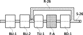
[8] フィルタA、及び、フィルタBUからなる群より選択される少なくとも1種のフィルタからなる第1基準フィルタの下流側から、第1基準フィルタの上流側へと、被精製液を返送可能な返送流通路を有する、[3]〜[7]のいずれかに記載のろ過装置。
[9] フィルタBは、流通路上においてフィルタAの下流側に配置されたフィルタBDを少なくとも含む、[1]〜[8]のいずれかに記載のろ過装置。
[10] 少なくとも1つのフィルタBDが、フィルタAより小さな孔径を有する、[9]に記載のろ過装置。
[11] 少なくとも1つのフィルタBDが、20nm以下の孔径を有する、[9]又は[10]に記載のろ過装置。
[12] フィルタBDが、ポリオレフィン、ポリアミド、ポリフルオロカーボン、ポリスチレン、ポリスルホン、及び、ポリエーテルスルホンからなる群より選択される少なくとも1種を含有する、[9]〜[11]のいずれかに記載のろ過装置。
[13] フィルタA、及び、フィルタBDからなる群より選択される少なくとも1種のフィルタからなる第2基準フィルタの下流側から、第2基準フィルタの上流側へと、被精製液を返送可能な返送流通路を有する、[9]〜[12]のいずれかに記載のろ過装置。
[14] 流入部及び流出部の間であって、流通路上において、フィルタAの上流側、又は、下流側に、フィルタAと直列に配置されたタンクを更に有する[1]〜[13]のいずれかに記載のろ過装置。
[15] 流入部及び流出部の間であって、タンクに対して流通路の上流側に、タンクと直列に配置された、孔径20nm以上のフィルタCを更に有する[14]に記載のろ過装置。
[16] 薬液が、現像液、リンス液、ウェハ洗浄液、ライン洗浄液、プリウェット液、ウェハリンス液、レジスト液、下層膜形成用液、上層膜形成用液、及び、ハードコート形成用液からなる群より選択される少なくとも1種であるか、又は、水性現像液、水性リンス液、剥離液、リムーバー、エッチング液、酸性洗浄液、及び、リン酸、リン酸−過酸化水素水混合液からなる群より選択される少なくとも1種である[1]〜[15]のいずれかに記載のろ過装置。
[17] [1]〜[16]のいずれかに記載のろ過装置と、ろ過装置の流入部に接続された少なくとも1つの蒸留器と、を有する精製装置。
[18] 少なくとも1つの蒸留器は、直列に接続された複数の蒸留器を含む、[17]に記載の精製装置。
[19] 被精製液を精製して薬液を得る、薬液の製造方法であって、[1]〜[16]のいずれかに記載のろ過装置を用いて、被精製液を精製して薬液を得る、ろ過工程を有する、薬液の製造方法。
[20] ろ過工程の前に、フィルタA、及び、フィルタBを洗浄するフィルタ洗浄工程を更に有する、[19]に記載の薬液の製造方法。
[21] ろ過工程の前に、ろ過装置の接液部を洗浄する装置洗浄工程を更に有する、[19]又は[20]に記載の薬液の製造方法。
[22] 被精製液を精製して薬液を得る、薬液の製造方法であって、被精製液を、ポリフルオロカーボン製の多孔質基材と、多孔質基材を覆うように配置された親水性基を有する樹脂を含有する被覆層を含むフィルタA、並びに、フィルタAとは異なるフィルタB、を用いてろ過して薬液を得る工程を有する、薬液の製造方法。[1] It has an inflow portion, an outflow portion, a filter A, and at least one filter B different from the filter A, and the filter A and the filter B are arranged in series between the inflow portion and the outflow portion. , A filtration device for purifying a liquid to be purified to obtain a chemical liquid, which has a flow passage from an inflow portion to an outflow portion, and the filter A is selected from the group consisting of a filter A1, a filter A2, and a filter A3. The filter A1 has a porous base material made of polytetrafluoroethylene and a coating layer containing a fluorinated ionomer arranged so as to cover the porous base material.
The fluorinated ionomer is a functional group that can be converted into an ethylene group and a hydrophilic group selected from the group consisting of -SO 2 F, -COOR, -COF, and a combination thereof, in which R is C 1. A fluorinated monomer unit containing a functional group of ~ C 20 alkyl radical or C 6 ~ C 20 aryl radical; the formulas (OF-1), (OF-2), and (OF) described later. The filter A2 contains a monomer unit derived from at least one bis-olefin selected from the group consisting of -3); and at least one selected from the group consisting of an iodine atom and a bromine atom; The filter A3 is a first composed of a porous base material made of polytetrafluoroethylene having a first hydrophilic group on the surface, which contains a copolymer having a repeating unit based on tetrafluoroethylene and another repeating unit. A laminated structure having a layer and a second layer made of a porous base material made of polytetrafluoroethylene which is arranged on the first layer and has a second hydrophilic group different from the first hydrophilic group on the surface. There is a filtration device.
[2] The first hydrophilic group and the second hydrophilic group are a polyether group, a hydroxyl group, a thioether group, a thiol group, a quaternary ammonium group, a carboxylic acid group, a sulfonic acid group, and a combination thereof. The filtration device according to [1], which is at least one selected from the group consisting of groups.
[3] The filtration device according to [1] or [2], wherein the filter B includes at least one filter BU arranged on the upstream side of the filter A on the flow path.
[4] The filtration device according to [3], wherein at least one filter BU has a pore diameter larger than that of the filter A.
[5] The filtration device according to [3] or [4], wherein at least one filter BU has a pore size of 20 nm or more.
[6] The filtration device according to any one of [3] to [5], wherein the at least one filter BU contains a resin having an ion exchange group.
[7] The filtration apparatus according to [6], wherein the ion exchange group is at least one selected from the group consisting of an acid group, a base group, an amide group, and an imide group.
[8] The liquid to be purified can be returned from the downstream side of the first reference filter consisting of at least one filter selected from the group consisting of the filter A and the filter BU to the upstream side of the first reference filter. The filtration device according to any one of [3] to [7], which has a return flow passage.
[9] The filtration device according to any one of [1] to [8], wherein the filter B includes at least a filter BD arranged on the downstream side of the filter A on the flow path.
[10] The filtration device according to [9], wherein at least one filter BD has a pore diameter smaller than that of the filter A.
[11] The filtration device according to [9] or [10], wherein at least one filter BD has a pore size of 20 nm or less.
[12] The method according to any one of [9] to [11], wherein the filter BD contains at least one selected from the group consisting of polyolefin, polyamide, polyfluorocarbon, polystyrene, polysulfone, and polyethersulfone. Filtration device.
[13] The liquid to be purified can be returned from the downstream side of the second reference filter consisting of at least one filter selected from the group consisting of the filter A and the filter BD to the upstream side of the second reference filter. The filtration device according to any one of [9] to [12], which has a return flow passage.
[14] Of [1] to [13], the tanks arranged in series with the filter A are further provided on the upstream side or the downstream side of the filter A on the flow path between the inflow part and the outflow part. The filtration device according to any one.
[15] The filtration device according to [14], further comprising a filter C having a pore diameter of 20 nm or more arranged in series with the tank between the inflow portion and the outflow portion and on the upstream side of the flow path with respect to the tank. ..
[16] A group in which the chemical solution consists of a developing solution, a rinsing solution, a wafer cleaning solution, a line cleaning solution, a pre-wet solution, a wafer rinsing solution, a resist solution, a lower layer film forming solution, an upper layer film forming solution, and a hard coat forming solution. At least one selected from the above, or from the group consisting of an aqueous developer, an aqueous rinse solution, a stripping solution, a remover, an etching solution, an acidic cleaning solution, and a phosphoric acid, a phosphoric acid-hydrogenated water mixed solution. The filtration device according to any one of [1] to [15], which is at least one selected.
[17] A purification apparatus comprising the filtration apparatus according to any one of [1] to [16] and at least one distiller connected to an inflow portion of the filtration apparatus.
[18] The purification apparatus according to [17], wherein at least one distiller comprises a plurality of distillers connected in series.
[19] A method for producing a chemical solution, which purifies a chemical solution to be purified to obtain a chemical solution, and purifies the chemical solution to be purified using the filtration device according to any one of [1] to [16]. A method for producing a chemical solution, which comprises a filtration step.
[20] The method for producing a chemical solution according to [19], further comprising a filter cleaning step of cleaning the filter A and the filter B before the filtration step.
[21] The method for producing a chemical solution according to [19] or [20], further comprising an apparatus cleaning step of cleaning the wetted portion of the filtration apparatus before the filtration step.
[22] A method for producing a chemical solution, which purifies a solution to be purified to obtain a drug solution, wherein the solution to be purified is a porous base material made of polyfluorocarbon and hydrophilic so as to cover the porous base material. A method for producing a chemical solution, which comprises a step of obtaining a chemical solution by filtering using a filter A including a coating layer containing a resin having a group and a filter B different from the filter A.
本発明によれば、優れた欠陥抑制性能を有する薬液を製造可能なろ過装置を提供できる。また、本発明は、精製装置、及び、薬液の製造方法も提供できる。 According to the present invention, it is possible to provide a filtration device capable of producing a chemical solution having excellent defect suppressing performance. The present invention can also provide a purification apparatus and a method for producing a chemical solution.
なお、本明細書において、薬液の「欠陥抑制性能」は、実施例に記載した方法により評価される薬液の性能を意味する。半導体基板の製造に用いられる薬液には、薬液の種類及び役割に応じたそれぞれの「欠陥抑制性能」が求められる。
本明細書においては、プリウェット液、現像液、及び、リンス液等のレジスト膜の形成の際に用いられる薬液については、後述する実施例における[試験例1]に記載した残渣欠陥をリソグラフィープロセスにおける欠陥の代表的な指標値のひとつとして捉え、残渣欠陥抑制性能を「欠陥抑制性能」とする。また、樹脂を含有し、レジスト膜の形成に用いられるレジスト樹脂組成物については、後述する実施例における[試験例3]に記載したブリッジ欠陥をレジスト樹脂組成物に由来するリソグラフィープロセスにおける欠陥の代表的な指標値のひとつとして捉え、ブリッジ欠陥抑制性能を「欠陥抑制性能」とする。また、エッチング液、及び、レジスト剥離液等として用いられる薬液については、後述する実施例における[試験例2]に記載したパーティクル欠陥を薬液由来の欠陥の代表的な指標値のひとつとして捉え、パーティクル欠陥抑制性能を「欠陥抑制性能」とする。
以下、単に「欠陥抑制性能」という場合、薬液の種類に応じたそれぞれの欠陥抑制性能(残渣欠陥抑制性能、ブリッジ欠陥抑制性能、又は、パーティクル欠陥抑制性能)を意味する。In the present specification, the "defect suppression performance" of the chemical solution means the performance of the chemical solution evaluated by the method described in the examples. The chemicals used in the manufacture of semiconductor substrates are required to have "defect suppression performance" according to the type and role of the chemicals.
In the present specification, with respect to the chemical solution used for forming a resist film such as a pre-wet solution, a developing solution, and a rinsing solution, the residue defects described in [Test Example 1] in Examples described later are subjected to a lithography process. It is regarded as one of the typical index values of defects in the above, and the residual defect suppression performance is referred to as "defect suppression performance". Regarding the resist resin composition containing a resin and used for forming the resist film, the bridge defects described in [Test Example 3] in Examples described later are representative of defects in the lithography process derived from the resist resin composition. Bridge defect suppression performance is referred to as "defect suppression performance" as one of the standard index values. Regarding the chemical solution used as the etching solution, the resist stripping solution, etc., the particle defects described in [Test Example 2] in the examples described later are regarded as one of the representative index values of the defects derived from the chemical solution, and the particles. Defect suppression performance is referred to as "defect suppression performance".
Hereinafter, the term "defect suppression performance" simply means each defect suppression performance (residual defect suppression performance, bridge defect suppression performance, or particle defect suppression performance) according to the type of the chemical solution.
以下、本発明について詳細に説明する。
以下に記載する構成要件の説明は、本発明の代表的な実施形態に基づいてなされることがあるが、本発明はそのような実施形態に制限されない。
なお、本明細書において、「〜」を用いて表される数値範囲は、「〜」の前後に記載される数値を下限値及び上限値として含む範囲を意味する。Hereinafter, the present invention will be described in detail.
The description of the constituent elements described below may be based on typical embodiments of the present invention, but the present invention is not limited to such embodiments.
In the present specification, the numerical range represented by using "~" means a range including the numerical values before and after "~" as the lower limit value and the upper limit value.
[ろ過装置]
本発明の実施形態に係るろ過装置は、流入部と、流出部と、フィルタAと、フィルタAとは異なる少なくとも1つのフィルタBと、を有し、フィルタA及びフィルタBは、流入部及び流出部の間に直列に配置され、流入部から流出部にいたる流通路(被精製液の流れる経路)を有するろ過装置であって、(言い換えれば、流入部と流出部との間に、フィルタAと上記フィルタAとは異なる少なくとも1つのフィルタBとが直列に配置され、流入部から流出部にいたる流通路を有する過装置であって、)フィルタAは、後述するフィルタA1、フィルタA2、及び、フィルタA3からなる群より選択される、ろ過装置である。ろ過装置は、流入部から流出部にいたる流通路を有し、流入部と流出部との間にフィルタAと上記フィルタAとは異なる少なくとも1つのフィルタBとが直列に配置されている。[Filtration device]
The filtration device according to the embodiment of the present invention includes an inflow portion, an outflow portion, a filter A, and at least one filter B different from the filter A, and the filter A and the filter B include an inflow portion and an outflow portion. A filtration device arranged in series between the portions and having a flow path (flow path for the liquid to be purified) from the inflow portion to the outflow portion (in other words, a filter A between the inflow portion and the outflow portion). And at least one filter B different from the above filter A are arranged in series and have a flow path from the inflow part to the outflow part.) The filter A is a filter A1, a filter A2, and a filter A2 described later. , A filtration device selected from the group consisting of filters A3. The filtration device has a flow passage from the inflow portion to the outflow portion, and a filter A and at least one filter B different from the filter A are arranged in series between the inflow portion and the outflow portion.
なお、本明細書において、フィルタAとフィルタBとが異なる、とは、孔径、細孔構造、及び、材料(含有する材料成分等)からなる群より選択される少なくとも1種の項目が異なることを意味する。 In the present specification, the difference between the filter A and the filter B means that at least one item selected from the group consisting of the pore size, the pore structure, and the material (containing material component, etc.) is different. Means.
一般に、薬液の欠陥抑制性能に関係する薬液中の不純物としては、例えば、ゲル状の有機化合物(特に高分子化合物)成分、無機微粒子、及び、無機イオン等が想定される。
これらのうち、薬液中の固形分となり得るゲル状の高分子化合物、又は、無機微粒子は、フィルタが有するふるい効果により除去されやすく、結果として、得られる薬液の欠陥抑制性能が向上するものと想定される。
一方、粒子以外の無機成分、及び、イオン性の成分は、フィルタが有する吸着機能(イオン相互作用による吸着、及び、親疎水性の相互作用による吸着等)により除去されやすく、結果として、得られる薬液の欠陥抑制性能が向上するものと想定される。In general, as impurities in the chemical solution related to the defect suppressing performance of the chemical solution, for example, gel-like organic compound (particularly polymer compound) components, inorganic fine particles, inorganic ions and the like are assumed.
Of these, it is assumed that gel-like polymer compounds or inorganic fine particles that can be solids in the chemical solution are easily removed by the sieving effect of the filter, and as a result, the defect suppression performance of the obtained chemical solution is improved. Will be done.
On the other hand, inorganic components other than particles and ionic components are easily removed by the adsorption function of the filter (adsorption by ionic interaction, adsorption by prohydrophobic interaction, etc.), and as a result, the obtained chemical solution. It is expected that the defect suppression performance of the
ふるい効果を有するフィルタと吸着効果のあるフィルタとをろ過装置の流通路上に直列に配置すると、それぞれのフィルタを単独で使用した場合に得られる薬液が有するよりも、より優れた欠陥抑制性能を有する薬液が得られることが本発明者らによって初めて知見された。本発明者らは、このような結果が得られたメカニズムを以下のように推測している。 When a filter having a sieving effect and a filter having an adsorption effect are arranged in series on the flow path of the filtration device, they have better defect suppression performance than the chemical solution obtained when each filter is used alone. It was first discovered by the present inventors that a chemical solution can be obtained. The present inventors speculate the mechanism by which such a result was obtained as follows.
本発明者らの検討によれば、単独では欠陥源とはならないような微小ゲル(有機化合物を含有する)と、無機微粒子及び/又は無機イオンとが相互作用したり、単独では欠陥源とならない微小無機微粒子及びトレースメタル等とゲル状の有機化合物とが相互作用したり、及び、微小ゲルと微小無機微粒子及びトレースメタル等とが相互作用することによって、欠陥が生ずる場合があることが明らかとなっている。
特に、微小ゲルは、薬液中では溶媒和の影響で分子ふるい効果によるろ過では充分に除去しきれず、薬液をウェハ上に塗布した後、乾燥させる際に溶媒和の効果が低減することでゲルを形成するため、欠陥の発生要因の1つとなるものと想定される。According to the studies by the present inventors, microgels (containing organic compounds) that cannot be a defect source by themselves and inorganic fine particles and / or inorganic ions interact with each other or do not become a defect source by themselves. It has been clarified that defects may occur due to the interaction between the fine inorganic fine particles and the trace metal and the gel-like organic compound, and the interaction between the fine gel and the fine inorganic fine particles and the trace metal. It has become.
In particular, microgels cannot be sufficiently removed by filtration by the molecular sieving effect due to the influence of solvation in the chemical solution, and the effect of solvation is reduced when the chemical solution is applied on the wafer and then dried to make the gel. Since it is formed, it is assumed to be one of the causes of defects.
このような複合的な欠陥源に対しては、相互作用する原因成分それぞれの除去が効果的であり、微小ゲル成分、及び、微小ゲル成分と相互作用しうる無機の超微粒子成分、及び、無機イオン成分を、ふるい効果及び吸着効果により除去することで、欠陥のさらなる低減に繋げることができると想定される。 For such a complex defect source, removal of each of the interacting causative components is effective, and the microgel component, the inorganic ultrafine particle component that can interact with the microgel component, and the inorganic It is assumed that removing the ionic components by the sieving effect and the adsorption effect can lead to further reduction of defects.
本実施形態に係るろ過装置は、後述するフィルタAによるふるい効果と、更に組み合わせるフィルタによるイオン源、及び/又は、無機微粒子の除去効果との組合せにより、相互作用によって欠陥を生じやすくなる原因となる物質を被精製液中から効率的に除去することができ、結果として、薬液中の欠陥低減効果をより向上させることができるものと推測される。
以下では、上記ろ過装置について、図面を用いて説明する。なお、本発明の実施形態に係るろ過装置はフィルタAとフィルタBとが流通路上に直列に配置されているため、被精製液は、フィルタA及びフィルタB(又は、フィルタB及びフィルタA)によって順次ろ過される。以下、本発明の実施形態に係るろ過装置について説明するが、以下の説明では、フィルタに導入した被精製液の全量をフィルタでろ過する、全量ろ過方式(デッドエンド方式)のろ過装置を例示する。しかし、本発明の実施形態に係るろ過装置としては上記に制限されず、導入した被精製液を精製済み被精製液と濃縮液とに分離する(更に濃縮液を再度被精製液としてフィルタに導入する場合もある)クロスフロー方式のろ過装置であってもよく、これらを組み合わせた方式であってもよい。The filtration device according to the present embodiment causes defects to be easily generated by interaction due to the combination of the sieving effect by the filter A described later and the ion source and / or the removal effect of the inorganic fine particles by the combined filter. It is presumed that the substance can be efficiently removed from the liquid to be purified, and as a result, the effect of reducing defects in the chemical liquid can be further improved.
Hereinafter, the filtration device will be described with reference to the drawings. In the filtration device according to the embodiment of the present invention, since the filter A and the filter B are arranged in series on the flow path, the liquid to be purified is supplied by the filter A and the filter B (or the filter B and the filter A). It is filtered sequentially. Hereinafter, the filtration device according to the embodiment of the present invention will be described. In the following description, a total amount filtration method (dead end method) filtration device in which the entire amount of the liquid to be purified introduced into the filter is filtered by the filter will be exemplified. .. However, the filtration device according to the embodiment of the present invention is not limited to the above, and the introduced liquid to be purified is separated into a purified liquid to be purified and a concentrated liquid (further, the concentrated liquid is introduced into the filter again as a liquid to be purified). It may be a cross-flow type filtration device, or a method in which these may be combined.
〔第一実施形態〕
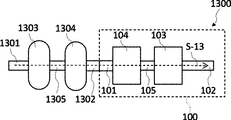
図1は、本発明の第一実施形態に係るろ過装置を表す模式図である。
ろ過装置100は、流入部101及び流出部102の間に、フィルタAであるフィルタ103及び上記フィルタ103とは異なるフィルタ104(フィルタBUに該当する)が配管105を介して直列に配置されたろ過装置である。
流入部101、フィルタ104、配管202、フィルタ103、及び、流出部102は、それぞれの内部に被精製液を流通できるよう構成されており、上記部材が連結されて、流通路S1(被精製液が流れる経路)が形成されている。[First Embodiment]
FIG. 1 is a schematic view showing a filtration device according to the first embodiment of the present invention.
In the
The
流入部101、及び、流出部102としては、ろ過装置に被精製液を導入し、及び、排出できればその形態としては特に制限されないが、典型的には、流入口と流出口とを有する中空円筒状の配管(流入部、及び、流出部)等が挙げられる。以下流出部と流入部とがそれぞれ配管である形態を例に説明する。
流入部101、配管105、及び、流出部102の形態としては特に制限されないが、典型的には、内部に被精製液を流通可能に形成された中空円筒状の形態が挙げられる。これらの材料としては特に制限されないが、接液部(被精製液をろ過するに際して、被精製液が接触する可能性のある部分)は、後述する耐腐食材料を材料成分(構成する成分)として含有することが好ましい。言い換えれば、後述する耐腐食材料を用いて形成されていることが好ましい。The form of the
The form of the
ろ過装置100の流入部101から導入された被精製液は、流通路S1に沿ってろ過装置100内を流通し、その間にフィルタ103(フィルタA)、及び、フィルタ104(フィルタBU)によって順次ろ過されて、流出部102からろ過装置100外へと排出される。なお被精製液の形態については後述する。
なお、ろ過装置100は、被精製液を流通させる目的で、流通路S1上に(例えば、流入部101、配管105、及び、流出部102等)に、図示しないポンプ、ダンパ、及び、弁等を有していてもよい。なお、ろ過装置100内の流通路に被精製液を流通させる方法としては上記に制限されず、流入部に、加圧した被精製液を導入する方法であってもよい。The liquid to be purified introduced from the
The
フィルタ103(フィルタA)及びフィルタ104(フィルタBU)の形態としては特に制限されない。フィルタA及びフィルタBの形態としては、例えば、平面状、プリーツ状、らせん状、及び、中空円筒状等が挙げられる。なかでも取り扱い性により優れる点で、典型的には、被精製液が透過可能な材料成分で形成された、及び/又は、被精製液が透過可能な構造である、芯材と、上記心材に巻き回される形で芯材上に配置されたフィルタとを有するカートリッジフィルタの形態が好ましい。この場合、芯材の材料成分としては特に制限されないが、後述する耐腐食材料から形成されることが好ましい。 The form of the filter 103 (filter A) and the filter 104 (filter BU) is not particularly limited. Examples of the form of the filter A and the filter B include a planar shape, a pleated shape, a spiral shape, a hollow cylindrical shape, and the like. Among them, the core material and the core material, which are typically formed of a material component that allows the liquid to be purified to permeate and / or have a structure that allows the liquid to be purified to permeate, are superior in terms of handleability. The form of a cartridge filter having a filter arranged on the core material in a wound form is preferable. In this case, the material component of the core material is not particularly limited, but it is preferably formed from a corrosion-resistant material described later.
フィルタの配置の方法としては特に制限されないが、典型的には、少なくとも1つの入口及び少なくとも1つの出口を含み、入口と出口との間に少なくとも1つの流通路が形成された、図示しないハウジング内に配置されることが好ましい。その場合、フィルタはハウジングの内の流通路を横切るように配置される。ハウジング内に形成された流通路は、流通路S1の一部をなし、被精製液は流通路S1を流通する際に、流通路S1を横切るように配置されたフィルタによってろ過される。 The method of arranging the filter is not particularly limited, but typically, in a housing (not shown) including at least one inlet and at least one outlet, and at least one flow path is formed between the inlet and the outlet. It is preferable to be arranged in. In that case, the filter is arranged across the flow path within the housing. The flow path formed in the housing forms a part of the flow path S1, and the liquid to be purified is filtered by a filter arranged so as to cross the flow path S1 when flowing through the flow path S1.
ハウジングの材料成分としては特に制限されないが、被精製液と適合できるあらゆる不浸透性の熱可塑性材料成分を含めて任意の適切な硬い不浸透性の材料成分が挙げられる。例えば、ハウジングはステンレス鋼などの金属、又はポリマーから製作できる。ある実施形態において、ハウジングはポリアクリレート、ポリプロピレン、ポリスチレン、又はポリカーボネート等のポリマーである。
また、より優れた本発明の効果を有するろ過装置が得られる点で、ハウジングの接液部の少なくとも一部、好ましくは接液部の表面積に対して90%、より好ましくは接液部の表面積に対して99%は、後述する耐腐食材料からなることが好ましい。なお、本明細書において接液部とは、被精製液が接触する可能性のある部分(但し、フィルタ自体を除く)を意味し、ハウジング等のユニットの内壁等を意味する。The material component of the housing is not particularly limited, and examples thereof include any suitable hard impermeable material component including any impermeable thermoplastic material component compatible with the liquid to be purified. For example, the housing can be made from a metal such as stainless steel or a polymer. In certain embodiments, the housing is a polymer such as polyacrylate, polypropylene, polystyrene, or polycarbonate.
Further, in that a filtration device having a more excellent effect of the present invention can be obtained, at least a part of the wetted portion of the housing, preferably 90% of the surface area of the wetted portion, more preferably the surface area of the wetted portion. On the other hand, 99% is preferably made of a corrosion-resistant material described later. In the present specification, the wetted portion means a portion (however, excluding the filter itself) that the liquid to be purified may come into contact with, and means an inner wall or the like of a unit such as a housing.
<フィルタA>
本発明の実施形態に係るフィルタAは、以下に説明するフィルタA1、フィルタA2、及び、フィルタA3からなる群より選択される。<Filter A>
The filter A according to the embodiment of the present invention is selected from the group consisting of the filter A1, the filter A2, and the filter A3 described below.
(フィルタA1)
フィルタA1は、ポリテトラフルオロエチレン製の多孔質基材と、上記多孔質基材を覆うように配置されたフッ素化イオノマーを含有する被覆層とを有し、上記フッ素化イオノマーは、少なくとも後述する2種のモノマー単位と、ヨウ素原子、及び、臭素原子からなる群より選択される少なくとも1種を含有する。(Filter A1)
The filter A1 has a porous base material made of polytetrafluoroethylene and a coating layer containing a fluorinated ionomer arranged so as to cover the porous base material, and the fluorinated ionomer is at least described later. It contains two types of monomer units and at least one type selected from the group consisting of an iodine atom and a bromine atom.
上記フィルタA1の典型例としては、フッ素化イオノマーを溶解又は分散させて含有するフルオロカーボン液状媒体を含むフルオロカーボン液体組成物であって、そのフッ素化イオノマーの少なくとも90質量%が、200ナノメートル(nm)未満、一部の変形例においては125nm未満、他の変形例においては40nm未満、なお更に他の変形例においては15nm未満の粒度の粒子からなる、フルオロカーボン液体組成物により、被覆層が形成された、被覆層付き多孔質基材(ポリテトラフルオロエチレン製)を包含する。フッ素化イオノマーは、380g/当量〜620g/当量の間の当量重量を有するのが好ましい。フッ素化イオノマーは、エチレン性基と親水性基に変換可能な官能基とを含有するフッ素化モノマー単位を含み、その変換可能な基は、−SO2F、−COOR、−COF及びこれらの組み合わせからなる群より選択され、ここで、Rは、C1〜C20アルキルラジカル又はC6〜C20アリールラジカルである。フッ素化イオノマーは、更に、式(OF−1)、(OF−2)、(OF−3)又はそれらの組み合わせの間で選択されるビス−オレフィンに由来するモノマー単位を含み、ここで、(OF−1)は、構造:

フッ素化イオノマーは、更に、ヨウ素及び/又は臭素原子を含む。一部の変形例において、このヨウ素及び/又は臭素原子は、イオノマー主鎖の末端位にあり、このヨウ素及び/又は臭素原子は、式:X1(CF)nX2のフルオロカーボン連鎖移動剤に由来し、式中、X1及びX2は、I、Br及びこれらの組み合わせからなる群より選択される。一部の変形例において、このヨウ素及び/又は臭素原子の含有量は、イオノマーに基づき、0.1質量%〜5質量%の間である。 Fluorinated ionomers further contain iodine and / or bromine atoms. In some modifications, the iodine and / or bromine atom is at the terminal position of the ionomer main chain, and the iodine and / or bromine atom is derived from a fluorocarbon chain transfer agent of formula: X1 (CF) nX2. In the formula, X1 and X2 are selected from the group consisting of I, Br and combinations thereof. In some modifications, the content of this iodine and / or bromine atom is between 0.1% and 5% by weight, based on the ionomer.
一部の変形例において、フッ素化イオノマーは、テトラフルオロエチレンを含むモノマー単位、エチレン性基と親水性基に変換可能な官能基とを含有するフッ素化モノマー単位を含み、この親水性基に変換可能な官能基は、−SO2F、−COOR、−COF及びこれらの組み合わせからなる群より選択され、ここで、Rは、C1〜C20アルキルラジカル又はC6〜C20アリールラジカルである。このフッ素化イオノマーは、更に、式:R1R2C=CH−(CF2)m−CH=CR5R6のビス−オレフィンに由来するモノマー単位を含み、式中:mは、2〜10の間の整数であり、R1、R2、R5、R6は、互いに同一又は異なり、H又はC1〜C5アルキル基である。このフッ素化イオノマーは、更に、主鎖の末端位にヨウ素及び/又は臭素原子を含み、このヨウ素及び/又は臭素原子は、式:X1(CF)nX2のフルオロカーボン連鎖移動剤に由来し、式中、X1及びX2は、I、Br及びこれらの組み合わせからなる群より選択される。In some modifications, the fluorinated ionomer comprises a monomer unit containing tetrafluoroethylene, a fluorinated monomer unit containing an ethylenic group and a functional group convertible into a hydrophilic group, and converted to this hydrophilic group. functional groups, -SO 2 F, -COOR, it is selected from the group consisting of -COF and combinations thereof, wherein, R represents is
一部の変形例において、エチレン性基と親水性基に変換可能な官能基とを含有するフッ素化モノマー単位は、式:CF2=CF−O−CF2CF2SO2Fを有する。In some modifications, the fluorinated monomeric unit containing an ethylenic group and a functional group convertible into a hydrophilic group has the formula: CF 2 = CF-O-CF 2 CF 2 SO 2 F.
変形例において、フルオロカーボン液体組成物は、追加的に、架橋剤及びラジカル開始剤を含み得る。一部の変形例において、架橋剤は、式:R1R2C=CH−(CF2)m−CH=CR5R6のビス−オレフィンであり得る、又はそのビス−オレフィンであり、式中:m=2〜10であり、R1、R2、R5、R6は、互いに同一又は異なり、H又はC1〜C5アルキル基である。ラジカル開始剤は、有機ジアルキルペルオキシドであり得る、又は有機ジアルキルペルオキシドであり、好ましくは、2,5−ジ(t−ブチルペルオキシ)−2,5−ジメチルヘキサンである。In a modified example, the fluorocarbon liquid composition may additionally comprise a cross-linking agent and a radical initiator. In some modifications, the cross-linking agent can be a bis-olefin of the formula: R1R2C = CH- (CF 2 ) m-CH = CR5R6, or a bis-olefin thereof, in the formula: m = 2-10. R1, R2, R5, and R6 are the same or different from each other and are H or C 1 to C 5 alkyl groups. The radical initiator can be an organic dialkyl peroxide, or is an organic dialkyl peroxide, preferably 2,5-di (t-butylperoxy) -2,5-dimethylhexane.
フルオロカーボン液体組成物の一部の変形例において、フッ素化イオノマーの少なくとも95質量%が、200ナノメートル(nm)未満の粒度の粒子から、他の変形例においては125nm未満の粒度の粒子からなり得、更に他の変形例において、フッ素化イオノマー粒度は40nm未満であり、なお更に他の変形例において、この粒度はより小さいか、又は15nm未満である。この液体組成物の他の変形例において、フッ素化イオノマーの少なくとも99質量%が、200ナノメートル(nm)未満の粒度の粒子から、他の変形例においては125nm未満の粒度の粒子からなり得、更に他の変形例において、この粒度は40nm未満であり、なお更に他の変形例において、この粒度はより小さいか、又は15nm未満である。本発明の更に他の変形例において、この液体組成物は、少なくとも99質量%が125nm未満の粒度の粒子からなるフッ素化イオノマーを有する。この液体組成物のなお更に他の変形例において、フッ素化イオノマーの少なくとも99質量%が、40nm未満の粒度の粒子からなる。この液体組成物のなおさらなる変形例において、フッ素化イオノマーの少なくとも99質量%が、15nm未満の粒度の粒子からなる。 In some variants of the fluorocarbon liquid composition, at least 95% by weight of the fluorinated ionomer may consist of particles with a particle size of less than 200 nanometers (nm), and in other variants with a particle size of less than 125 nm. In yet another variant, the fluorinated ionomer particle size is less than 40 nm, and in yet another variant, this particle size is smaller or less than 15 nm. In other variants of this liquid composition, at least 99% by weight of the fluorinated ionomer may consist of particles with a particle size of less than 200 nanometers (nm) and particles with a particle size of less than 125 nm in other variants. In yet another variant, the particle size is less than 40 nm, and in yet another variant, the particle size is smaller or less than 15 nm. In yet another variation of the invention, the liquid composition has a fluorinated ionomer consisting of particles with a particle size of at least 99% by weight less than 125 nm. In yet another variation of this liquid composition, at least 99% by weight of the fluorinated ionomer consists of particles with a particle size of less than 40 nm. In a further modification of this liquid composition, at least 99% by weight of the fluorinated ionomer consists of particles with a particle size of less than 15 nm.
フルオロカーボン液体組成物の別の変形例は、架橋性フッ素化イオノマーを溶解又は分散させて含有するフルオロカーボン液状媒体を含むフルオロカーボン液体組成物であり、その架橋性フッ素化イオノマーの少なくとも90質量%が、200nm未満、好ましくは125nm未満、より好ましくは40nm未満、なおより好ましくは15nm未満の粒度の粒子からなる。この液体組成物の一部の変形例において、液体組成物は、追加的に、架橋剤及びラジカル開始剤を含む。 Another modification of the fluorocarbon liquid composition is a fluorocarbon liquid composition containing a fluorocarbon liquid medium containing a crosslinked fluorinated ionomer dissolved or dispersed, wherein at least 90% by mass of the crosslinkable fluorinated ionomer is 200 nm. It consists of particles with a particle size of less than, preferably less than 125 nm, more preferably less than 40 nm, and even more preferably less than 15 nm. In some variations of this liquid composition, the liquid composition additionally comprises a cross-linking agent and a radical initiator.
の変形例は、フルオロカーボン液体組成物で被覆された多孔質基材を包含する。フィルタA1の別の変形例は、膜上でフッ素化イオノマー及びビス−オレフィンを架橋させるように硬化されたフルオロカーボン液体組成物で被覆された多孔質基材である。フィルタA1の更に別の変形例において、硬化され架橋されたイオノマーをその表面及び細孔上に有する多孔質基材は、その変換可能な基が塩基及び酸で活性化されて親水性基を形成している。 Modifications include a porous substrate coated with a fluorocarbon liquid composition. Another variant of filter A1 is a porous substrate coated with a fluorocarbon liquid composition that has been cured to crosslink the fluorinated ionomer and bis-olefin on the membrane. In yet another modification of filter A1, a porous substrate having cured and crosslinked ionomers on its surface and pores has its convertible groups activated by bases and acids to form hydrophilic groups. doing.
フィルタA1の変形例は、メタノールと水とを含有する溶液で湿潤可能な、非脱湿潤性の、微孔質膜複合材料を含む。この微孔質膜複合材料は、多孔質基材の流体接触表面及び細孔上に架橋コーティングを有し、このコーティングは、親水性基を含んだ非晶質フッ素化イオノマーを含む。一部の変形例において、フッ素化イオノマーは、非晶質である部分が大半で、結晶質又は部分的に結晶質である部分を僅かに有する。多孔質基材上のコーティング中のイオノマーは、疎水性基で架橋される。微孔質膜複合材料は、水中でのオートクレーブ処理後に非脱湿潤性であり、27×10−5N/cm以上の表面エネルギを有する。Modifications of filter A1 include a non-dehumidifying, microporous membrane composite that can be moistened with a solution containing methanol and water. The microporous membrane composite has a cross-linked coating on the fluid contact surface and pores of the porous substrate, the coating containing an amorphous fluorinated ionomer containing hydrophilic groups. In some modifications, the fluorinated ionomer is mostly amorphous and has a few crystalline or partially crystalline moieties. Ionomers in the coating on the porous substrate are crosslinked with hydrophobic groups. The microporous membrane composite is non-dehumidifying after autoclaving in water and has a surface energy of 27 × 10-5 N / cm or greater.
フィルタA1の変形例は、0.45ミクロン以下の細孔径、一部の変形例においては0.1ミクロン以下の定格細孔径を有する多孔質基材と、多孔質基材の細孔を含めた表面を被覆する非晶質架橋フッ素化イオノマーを含むコーティングとを含む、メタノールと水とを含有する溶液で湿潤可能な微孔質膜複合材料である。多孔質基材上の架橋コーティングは、97,905Paの圧力で500mLのイソプロピルアルコールを用いて測定される場合、被覆されていない多孔質基材についての平均イソプロピルアルコール流動損失と比較して、82%以下の平均イソプロピルアルコール流動損失を有する微孔質膜複合材料をもたらす。フィルタA1の一部の変形例において、多孔質基材は、多層であり、1つ以上の保持層及び1つ以上の支持層を含む。架橋フッ素化イオノマーは、テトラフルオロエチレンを含むフッ素化モノマー単位;エチレン性不飽和と親水性基に変換可能な官能性前駆体基とを含有するフッ素化モノマー単位から形成され得る。この前駆体基は、−SO2F、−COOR、−COF及びこれらの組み合わせからなる群より選択され、ここで、Rは、C1〜C20アルキルラジカル又はC6〜C20アリールラジカルである。Modifications of the filter A1 included a porous substrate having a pore diameter of 0.45 micron or less, and some modifications having a rated pore diameter of 0.1 micron or less, and pores of the porous substrate. A microporous membrane composite that can be moistened with a solution containing methanol and water, including a coating containing an amorphous crosslinked fluorinated ionomer that coats the surface. The crosslinked coating on the porous substrate is 82% compared to the average isopropyl alcohol flow loss for the uncoated porous substrate when measured with 500 mL of isopropyl alcohol at a pressure of 97,905 Pa. It results in a microporous membrane composite material with the following average isopropyl alcohol flow loss. In some modifications of the filter A1, the porous substrate is multi-layered and includes one or more retaining layers and one or more supporting layers. Cross-linked fluorinated ionomers can be formed from fluorinated monomeric units containing tetrafluoroethylene; fluorinated monomeric units containing ethylenically unsaturated and functional precursor groups that can be converted to hydrophilic groups. The precursor groups, -SO 2 F, -COOR, is selected from the group consisting of -COF and combinations thereof, wherein, R represents is
架橋フッ素化イオノマーは、親水性基がない架橋基により形成され得、フィルタA1の変形例において、架橋剤は、式(I):
R1R2C=CH−(CF2)m−CH=CR5R6のビス−オレフィンに由来するか、このビス−オレフィンを含むか、又はこのビス−オレフィンからなる。なお、式中:m=2〜10であり、R1、R2、R5、R6は、互いに同一若しくは異なる、又はH若しくはC1〜C5アルキル基である。The crosslinked fluorinated ionomer can be formed by a crosslinked group without a hydrophilic group, and in the modified example of the filter A1, the crosslinked agent is of the formula (I) :.
R 1 R 2 C = CH- (CF 2 ) m- CH = CR 5 Derived from the bis-olefin of R 6 , contains or comprises this bis-olefin, or consists of this bis-olefin. In the formula: m = 2 to 10, and R 1 , R 2 , R 5 , and R 6 are the same or different from each other, or are H or C 1 to C 5 alkyl groups.
フッ素化イオノマーは、式:
X1(CF)nX2のフルオロカーボン連鎖移動剤に由来するヨウ素及び/又は臭素基を含み得る。なお、式中、X1及びX2は、I、Br及びこれらの組み合わせからなる群より選択される。The fluorinated ionomer is based on the formula:
It may contain iodine and / or bromine groups derived from the fluorocarbon chain transfer agent of X 1 (CF) n X 2. In the formula, X 1 and X 2 are selected from the group consisting of I, Br and combinations thereof.
エチレン性不飽和と親水性基に変換可能な官能基とを含有するフッ素化モノマー単位は、CF2=CF−O−CF2CF2SO2F単位を含むか、この単位からなるか、又はこの単位から実質的になり得る。変形例における、微孔質膜の表面及び細孔を被覆する、親水性基を有するフッ素化架橋イオノマーコーティングは、60nmol/cm2より高い、一部の変形例においては95nmol/cm2より高いイオン交換容量を有する、メタノールと水とを含有する溶液において湿潤可能な、微孔質膜複合材料をもたらす。有利なことに、フィルタA1の変形例における架橋フッ素化コーティングは、従来の親水性化された(hydrophilization)表面コーティング(例えば、微孔質膜上のポリビニルアルコールコーティング)よりも、酸化環境において、安定である。The fluorinated monomer unit containing an ethylenically unsaturated and a functional group convertible into a hydrophilic group comprises, consists of, or consists of CF 2 = CF-O-CF 2 CF 2 SO 2 F units. This unit can be substantial. The fluorinated crosslinked ionomer coating with hydrophilic groups covering the surface and pores of the microporous membrane in the variants is higher than 60 nmol / cm 2 and in some variants higher than 95 nmol / cm 2. It provides a microporous membrane composite that has an exchange capacity and can be wetted in a solution containing methanol and water. Advantageously, the crosslinked fluorinated coating in the modified example of filter A1 is more stable in an oxidizing environment than conventional hydrophilization surface coatings (eg, polyvinyl alcohol coatings on microporous membranes). Is.
フッ素化化合物又はフルオロカーボン化合物は、フッ素により置換された少なくとも1つの炭素水素結合又は少なくとも1つの炭素結合水素を有する、化合物、ポリマー、イオノマー、連鎖移動剤、架橋剤、及び、溶媒等をいう。変形例において、フッ素化化合物又はフルオロカーボン化合物は、炭素結合水素の全て又は実質的に全てはフッ素により置換されていない、化合物、ポリマー、イオノマー、連鎖移動剤、架橋剤、溶媒などをいう。過フッ素化化合物又はペルフルオロカーボン化合物は、全ての又は実質的に全ての炭素結合水素がフッ素により置換されている化合物(ポリマー、イオノマー、架橋基、連鎖移動剤などを含む)をいう。例えば、過フッ素化とは、存在する特性基の性質にその置換が実質的に影響を及ぼすような水素原子を除く、全ての水素原子が、フッ素原子により置換されている化合物に言及し得る。一部の残留水素化物、例えば、過フッ素化生成物の2質量%未満、場合によっては過フッ素化生成物の0.25質量%未満が、過フッ素化組成物中に存在し得る。例えば、ポリフッ化ビニリデンは、過フッ素化ポリマーではなくフルオロポリマーの一例であり、PFA、MFA、FEP、ポリテトラフルオロエチレン(PTFE)、これらのブレンドなどは、過フッ素化ポリマーの例である。多孔質膜に有用な過フッ素化熱可塑性ポリマーとしては、ペルフルオロアルコキシ(DupontのTeflon(登録商標)PFA、DaikinのNeoflon(登録商標)PFA、DupontのTeflon(登録商標)PFA Plus)、ペルフルオロメチルアルコキシ(Solvay SolexisのHyflon(登録商標)MFA)、フッ素化エチレンプロピレン(Dupontの(Teflon(登録商標))FEP)及びこれらのコポリマーが挙げられ得るが、これらに限定されない。これらの過フッ素化熱可塑性物質は、耐薬品性でかつ熱安定性であり、その結果、それらで作られた多孔質膜は、化学安定性及び熱安定性がより低いポリマーと比較して、明白な利点を有し得る。使用され得る他の有用な熱可塑性フルオロポリマーとしては、必要に応じて1種以上の他の非フッ素化モノマーと組み合わせて、フッ素化モノマー、例えば、とりわけ、フッ化ビニリデン(VF2)、ヘキサフルオロプロペン(HFP)、クロロトリフルオロエチレン(CTFE)、フッ化ビニル(VF)、トリフルオロエチレン(TrFE)、及びテトラフルオロエチレン(TFE)に由来するモノマー単位を含むホモポリマー及びコポリマーが挙げられ得る。 A fluorinated compound or a fluorocarbon compound refers to a compound, a polymer, an ionomer, a chain transfer agent, a cross-linking agent, a solvent, or the like having at least one carbon-hydrogen bond or at least one carbon-bonded hydrogen substituted with fluorine. In the modified examples, the fluorinated compound or the fluorocarbon compound refers to a compound, a polymer, an ionomer, a chain transfer agent, a cross-linking agent, a solvent, etc., in which all or substantially all of the carbon-bonded hydrogen is not replaced by fluorine. A perfluorinated compound or a perfluorinated carbon compound refers to a compound (including a polymer, an ionomer, a cross-linking group, a chain transfer agent, etc.) in which all or substantially all carbon-bonded hydrogens are substituted with fluorine. For example, hyperfluorination can refer to compounds in which all hydrogen atoms are substituted with fluorine atoms, except for hydrogen atoms whose substitutions substantially affect the properties of the characteristic groups present. Some residual hydrides, such as less than 2% by weight of the perfluorinated product, and in some cases less than 0.25% by weight of the perfluorinated product, may be present in the perfluorinated composition. For example, polyvinylidene fluoride is an example of a fluoropolymer rather than a perfluorinated polymer, and PFA, MFA, FEP, polytetrafluoroethylene (PTFE), blends thereof and the like are examples of perfluorinated polymers. Perfluoroalkoxy (DuPont's Teflon® PFA, Daikin's Neoflon® PFA, DuPont's Teflon® PFA Plus) and perfluoromethylalkoxy alkanes are examples of perfluoroalkoxy thermoplastic polymers that are useful for porous films. (Hyflon® MFA of Solvay Solexis), fluorinated ethylenepropylene (Dupont's (Teflon®) FEP) and copolymers thereof can be mentioned, but not limited to. These perfluorinated thermoplastics are chemical resistant and thermally stable, so that the porous membranes made from them are compared to polymers with lower chemical and thermal stability. It can have obvious advantages. Other useful thermoplastic fluoropolymers that may be used include fluorinated monomers, such as vinylidene fluoride (VF2), hexafluoropropene, in particular, in combination with one or more other non-fluorinated monomers as needed. Homopolymers and copolymers containing monomeric units derived from (HFP), chlorotrifluoroethylene (CTFE), vinyl fluoride (VF), trifluoroethylene (TrFE), and tetrafluoroethylene (TFE) can be mentioned.
フルオロ界面活性剤は、界面活性剤の少なくとも1つの水素原子がフッ素原子で置換されている、又は界面活性剤が1つ以上のフッ素原子を含有する、界面活性剤をいう。一部の変形例において、5,000質量百万分率(ppm)のイソプロピルアルコール中のフルオロ界面活性剤は、3M(商標)Novec(商標)FC4432である。Novec(商標)FC4432は、3M(商標)より入手可能な非イオン性ポリマーフルオロ界面活性剤である。 Fluorosurfactant refers to a surfactant in which at least one hydrogen atom of the surfactant is substituted with a fluorine atom, or the surfactant contains one or more fluorine atoms. In some modifications, the fluorosurfactant in 5,000 parts per million (ppm) isopropyl alcohol is 3M Novec ™ FC4432. Novec ™ FC4432 is a nonionic polymer fluorosurfactant available from 3M ™.
多孔質基材の外部表面及び細孔表面上の、フッ素化コーティング、又は変形例における過フッ素化コーティングは、被覆、硬化及び活性化の工程又は操作の後の微孔質膜複合材料の試料を湿潤させ、次いで、メタノールと水とを含有する様々な溶液での湿潤試験の間に、半透明の被覆微孔質膜中の不透明箇所を探すことによって特徴付けられ得る。本発明の1つの変形例において、このコーティングは、被覆微孔質膜複合材料のメチレンブルー染色された試料中に不透明箇所を探すことによって特徴付けられ得る。あるいは、メチレンブルー染料で染色された微孔質膜複合材料のデンシトメーター読取り値の差異が、微孔質支持体の液体接触表面を被覆する架橋イオノマーの均一性を特徴づけるために使用され得る。一部の実施形態において、架橋イオノマーコーティングは、メチレンブルー染色された被覆微孔質膜複合材料のデンシトメーター読取り値の相対標準偏差(平均で除した標準偏差)が、0.40未満であることによって特徴付けられる。他の実施形態において、架橋イオノマーコーティングは、メチレンブルー染色された被覆微孔質膜複合材料のデンシトメーター読取り値の相対標準偏差が、0.30未満であることによって特徴付けられる。更に他の実施形態において、架橋イオノマーコーティングの均一性は、メチレンブルー染色された被覆微孔質膜複合材料のデンシトメーター読取り値の相対標準偏差が、0.06未満であることによって特徴付けられる。 A fluorinated coating on the outer surface and pore surface of the porous substrate, or a hyperfluorinated coating in a variant, provides a sample of microporous membrane composite after coating, curing and activation steps or operations. It can be characterized by wetting and then looking for opaque spots in the translucent coated microporous membrane during wet tests with various solutions containing methanol and water. In one variant of the invention, the coating can be characterized by looking for opaque spots in a methylene blue stained sample of the coated microporous membrane composite. Alternatively, differences in densitometer readings of the microporous membrane composite dyed with methylene blue dye can be used to characterize the uniformity of the crosslinked ionomers that coat the liquid contact surface of the microporous support. In some embodiments, the crosslinked ionomer coating has a relative standard deviation (average divided standard deviation) of the densitometer readings of the methylene blue-stained coated microporous membrane composite material of less than 0.40. Characterized by. In other embodiments, the crosslinked ionomer coating is characterized by a relative standard deviation of the densitometer readings of the methylene blue stained coated microporous membrane composite material of less than 0.30. In yet another embodiment, the uniformity of the crosslinked ionomer coating is characterized by a relative standard deviation of the densitometer readings of the methylene blue stained coated microporous membrane composite material of less than 0.06.
フィルタA1の変形例における微孔質膜複合材料は、硬化され活性化された(−SO2F及び/又はCOFのような変換可能な官能性前駆体基が−SO3H及び/又はCOOHに転化された)微孔質膜複合材料試験試料を、イソプロパノール(IPA)に浸漬して、その微孔質膜複合材料を湿潤させることにより、メチレンブルーで染色され得る。湿潤された微孔質膜複合材料試験試料は、次いで、その微孔質膜複合材料試験試料表面の染色が影響を受けるまで、メチレンブルー染料の0.1%水溶液に浸漬され得る。次いで、染色された試料は、順次、水、IPA、及び水中で、膜から過剰な染料を除去するように攪拌されながら洗浄され得る。次いで、このメチレンブルー染色された微孔質膜複合材料は乾燥され、デンシトメトリーによって評価され得る。The microporous membrane composite in the modified example of filter A1 had a cured and activated (-SO 2 F and / or convertible functional precursor groups such as COF to -SO 3 H and / or COOH. The (converted) microporous membrane composite test sample can be stained with methylene blue by immersing the microporous membrane composite test sample in isopropanol (IPA) to wet the microporous membrane composite. The wet microporous membrane composite test sample can then be immersed in a 0.1% aqueous solution of the methylene blue dye until the staining of the microporous membrane composite test sample surface is affected. The stained sample can then be washed sequentially in water, IPA, and water with stirring to remove excess dye from the membrane. The methylene blue stained microporous membrane composite is then dried and can be evaluated by densitometry.
フィルタA1の変形例は、メタノールと水とを含有する溶液で湿潤される多孔質基材の表面及び細孔上に架橋非晶質イオノマーコーティングを含む非脱湿潤性の微孔質膜複合材料を包含する。変形例において、微孔質膜複合材料は、27×10−5N/cm以上(水中約80質量%MeOHで湿潤される)又は27×10−5N/cm以上の表面エネルギを有し得る。変形例において、微孔質膜複合材料は、40×10−5N/cm以上(水中約30質量%MeOHで湿潤される)の表面エネルギを有し得る。更に一部の他の変形例において、微孔質膜複合材料は、50×10−5N/cm以上(水中約15質量%MeOHで湿潤される)の表面エネルギを有し得る。なお更に他の変形例において、微孔質膜複合材料は、40×10−5N/cm〜50×10−5N/cmの間の表面エネルギを有し得る。有利なことに、こうした表面エネルギを有する変形例における微孔質膜複合材料は、多くの処理化学物質で直ちに湿潤され得るので、そのような微孔質膜複合材料を含有するフィルタを乾燥状態で梱包し、最終使用者に向けて発送することが可能となる。乾燥状態の微孔質膜複合材料を含有するフィルタは、製造業者にとっては予備湿潤(prewetting)及びオートクレーブ工程を無くすことにより製造費の削減となり得、予備湿潤されたより重い含水フィルタと比較して輸送費を削減し得る。最終使用者は、運転停止時間及び関連費用、並びに溶媒交換及び予備湿潤フィルタのコンディショニングより生じる廃棄物を無くし得るため、乾燥状態の微孔質膜複合材料を含有するフィルタから利益を得る。A variant of filter A1 is a non-dehumidifying microporous membrane composite containing a crosslinked amorphous ionomer coating on the surface and pores of a porous substrate that is moistened with a solution containing methanol and water. Include. In a modified example, the microporous membrane composite may have a surface energy of 27 × 10-5 N / cm or more (wet with about 80% by weight MeOH in water) or 27 × 10-5 N / cm or more. .. In a modified example, the microporous membrane composite may have a surface energy of 40 × 10-5 N / cm or more (wet with about 30% by weight MeOH in water). In yet some other variations, the microporous membrane composite may have a surface energy of 50 × 10-5 N / cm or greater (wet with about 15% by weight MeOH in water). In still yet another variation, microporous membrane composite material may have a surface energy of between 40 × 10 -5 N / cm~50 × 10 -5 N / cm. Advantageously, the microporous membrane composites in variants with such surface energies can be immediately wetted with many treated chemicals, so filters containing such microporous membrane composites in a dry state. It can be packed and shipped to the end user. Filters containing dry microporous membrane composites can reduce manufacturing costs by eliminating prewetting and autoclaving steps for manufacturers and transport compared to prewetting heavier water content filters. Costs can be reduced. The end user benefits from a filter containing a dry microporous membrane composite because it can eliminate downtime and associated costs, as well as waste generated from solvent exchange and pre-wetting filter conditioning.
変形例において、微孔質膜複合材料は、水でのオートクレーブ処理後に非脱湿潤性であり、更に言うと、水オートクレーブ前よりも水オートクレーブ後の方が微孔質複合材料膜の水流動時間が短く、その微孔質膜複合材料が非脱湿潤性のままであるようなコーティング構造を有する。 In the modified example, the microporous composite is non-dehumidifying after autoclaving with water, and more specifically, the water flow time of the microporous composite film after water autoclaving is greater than before water autoclaving. Has a coating structure such that the microporous membrane composite remains non-dehumidifying.
変形例における多孔質基材の液体接触表面上に架橋イオノマーを含むコーティングは、FTIRなどの分光技術によって、又は反射率などの光学的方法によって特徴づけられ得る。例えば、1つの変形例において、被覆多孔質基材は、そのコーティング中の親水性基を表示する染料で染色され、デンシトメーターでの反射率読取りが、微孔質膜複合材料上の様々な点で行われる。微孔質膜複合材料の変形例における多孔質基材上の架橋イオノマーコーティングは、化学処理後のその特性によって更に特徴付けられ得る。例えば、この処理は、微孔質膜複合材料の直径47mm試料を通しての、70℃〜80℃の間の温度にて、少なくとも80mL/分の流量での、5000質量百万分率(ppm)の3M(商標)Novec(商標)FC4432フルオロ界面活性剤を含有するイソプロピルアルコールと、メチレンブルー染色された微孔質膜複合材料との、4時間以上の貫流接触を含み得る。次いで、処理された被覆微孔質膜複合材料及び処理されていない被覆微孔質膜複合材料についてのデンシトメーター読取り値又は他の分光特性が比較され得る。一部の変形例において、被覆微孔質膜複合材料は、熱界面活性剤処理前の被覆微孔質膜複合材料の特性の平均と比較して、当該処理後の平均の差異が±9%未満である、デンシトメーター読取り値又は他の特性(例えば、親水性基のFTIR透過強度)を有する。微孔質膜複合材料の一部の変形例において、これらの平均(熱界面活性剤処理前後の特性)は、スチューデントt検定により95%の信頼限界(CL)で異ならない。本発明の更に一部の他の変形例において、これらの平均は、スチューデントt検定により95%の信頼限界で異ならず、デンシトメーター読取り値又は他の特性が、熱界面活性剤処理前の被覆微孔質膜複合材料の特性の平均と比較して、当該処理後の平均の差異が±9%未満である。被覆微孔質膜複合材料の一部の変形例は、処理前の被覆微孔質膜複合材料の特性の平均と比較して、処理後の平均の差異が±4%未満である、デンシトメーター読取り値又は他の特性を有する。一部の変形例において、これらの平均は95%の信頼限界で異ならず、特性は、処理前の被覆膜の特性の平均と比較して、処理後の平均の差異が±4%未満である。 The coating containing crosslinked ionomers on the liquid contact surface of the porous substrate in the modifications can be characterized by spectroscopic techniques such as FTIR or by optical methods such as reflectance. For example, in one variant, the coated porous substrate is dyed with a dye indicating the hydrophilic groups in its coating, and reflectance readings with a densitometer show various on microporous membrane composites. It is done at the point. The crosslinked ionomer coating on the porous substrate in the modified examples of the microporous membrane composite can be further characterized by its properties after chemical treatment. For example, this treatment involves a microporous membrane composite through a 47 mm diameter sample at a temperature between 70 ° C. and 80 ° C. at a flow rate of at least 80 mL / min and a fraction of 5000 mass per million (ppm). It may include pervasive contact of isopropyl alcohol containing a 3M Novec ™ FC4432 fluorosurfactant with a methylene blue-stained microporous membrane composite for at least 4 hours. Densitometer readings or other spectroscopic properties for treated and coated microporous membrane composites can then be compared. In some modifications, the coated microporous membrane composite has a ± 9% difference in average after the treatment compared to the average properties of the coated microporous membrane composite before the thermal surfactant treatment. Has less than a densitometer reading or other property (eg, FTIR permeation intensity of hydrophilic groups). In some variants of microporous membrane composites, these averages (characteristics before and after thermal surfactant treatment) do not differ with a 95% confidence limit (CL) by Student's t-test. In still some other variations of the invention, these averages do not differ with a 95% confidence limit by Student's t-test, and densitometer readings or other properties show the coating before thermal surfactant treatment. Compared to the average of the properties of the microporous membrane composite, the difference in the average after the treatment is less than ± 9%. Some variants of the coated microporous membrane composite have a difference of less than ± 4% of the average after treatment compared to the average of the properties of the coated microporous membrane composite before treatment. Has meter readings or other characteristics. In some variants, these averages did not differ with a confidence limit of 95%, and the properties were such that the difference between the averages after treatment was less than ± 4% compared to the average properties of the coating film before treatment. is there.
変形例における、メタノールと水との混合物を含有する溶液で湿潤可能であり、かつ非脱湿潤性である、微孔質膜複合材料は、高い透水性を有し得る。特に水オートクレーブ処理後に直径47mmの微孔質膜複合材料試料について測定された水流動時間に基づく変形例における微孔質膜複合材料についての計算透水度は、22.5℃で1000L/atm×時間×m2を超え得る。変形例において、直径47mmの微孔質膜複合材料試料について測定された水流動時間に基づく計算透水度は、22.5℃で1200L/atm×時間×m2より高い。更に他の変形例において、微孔質膜複合材料は、直径47mmの微孔質膜複合材料試料について測定された水流動時間に基づき、22.5℃で1800L/atm×時間×m2より高い計算透水度を有する。理論により拘束されることを望むものではないが、微孔質膜複合材料の変形例において達成されるより高い透水性及びより短い流動時間は、変形例における微孔質膜表面が、他の被覆膜と比較してより薄い架橋コーティングを有することを示唆している。更に、変形例における微孔質膜複合材料は、メチレンブルー染色された複合材料についての0.4未満のデンシトメーター読取り値の相対標準偏差、及び水中でのオートクレーブ試験に基づくこれらの複合材料の非脱湿潤特性により特徴付けられる架橋イオノマーコーティングを有する。The microporous membrane composite, which is wettable and non-dehumidifying with a solution containing a mixture of methanol and water in a modified example, can have high water permeability. In particular, the calculated water permeability of the microporous membrane composite in the modified example based on the water flow time measured for the microporous membrane composite sample with a diameter of 47 mm after the water autoclave treatment is 1000 L / atm × time at 22.5 ° C. Can exceed × m 2. In the modified example, the calculated water permeability based on the water flow time measured for the microporous membrane composite sample with a diameter of 47 mm is higher than 1200 L / atm × time × m 2 at 22.5 ° C. In yet another variant, the microporous membrane composite is higher than 1800 L / atm x time x m 2 at 22.5 ° C. based on the water flow time measured for the microporous membrane composite sample with a diameter of 47 mm. Has calculated water permeability. Although not desired to be constrained by theory, the higher permeability and shorter flow times achieved in the modified microporous membrane composites are such that the microporous membrane surface in the modified examples is subject to other coatings. It suggests that it has a thinner crosslinked coating compared to the cover film. In addition, the microporous membrane composites in the variants are the relative standard deviations of less than 0.4 densitometer readings for methylene blue stained composites, and the non-standard deviations of these composites based on underwater autoclave testing. It has a crosslinked ionomer coating characterized by dewetting properties.
米国特許第6,902,676号明細書及び米国特許第6,576,100号明細書に開示されている、フッ素化イオノマー、フッ素化モノマー、連鎖移動剤、ラジカル開始剤及び架橋剤が、変形例において、多孔質膜を被覆するために使用され得、これら2つの米国特許明細書の内容は、参照によりその全体が本明細書に援用される。一部の変形例において、−SO2F及び/又はCOF型の同じ若しくは異なる当量重量の1種以上のイオノマー、並びに溶媒が、イオノマーを含むコーティング溶液を形成するために使用され、一部の変形例において、この溶媒は、フルオロカーボン溶媒を含む。一部の変形例において、このコーティング溶液は、イオノマーの溶液及び離散粒子を含み得、更に他の変形例において、このコーティング溶液は、イオノマーの離散粒子を含み得る。これらのコーティング溶液は、多孔質基材を被覆するために使用される。Deformations of fluorinated ionomers, fluorinated monomers, chain transfer agents, radical initiators and cross-linking agents disclosed in US Pat. No. 6,902,676 and US Pat. No. 6,576,100. In an example, it can be used to coat a porous membrane, the contents of these two US patent specifications, which are hereby incorporated by reference in their entirety. In some variations, -
200nm以下の小さいイオノマー粒子を含有するコーティング溶液は、フルオロカーボン溶媒にフッ素化イオノマー又はフッ素化イオノマー前駆体を攪拌しながら溶解させ、続いて濾過又は遠心処理を行うことによって得られ得る。遠心処理は、高速で(例えば、10,000rpm以上で)約2時間にわたって行われ得る。したがって、結果として生じるイオノマー残留物は分離されており、小さいイオノマー粒子を含む透明液体組成物が得られる。使用されるフルオロカーボン溶媒に依存して、溶液中のコポリマー及び不溶性残留物の当量重量に関する分別効果が生じ得る。 A coating solution containing small ionomer particles of 200 nm or less can be obtained by dissolving a fluorinated ionomer or a fluorinated ionomer precursor in a fluorocarbon solvent with stirring, followed by filtration or centrifugation. Centrifugal treatment can be performed at high speed (eg, at 10,000 rpm or higher) for about 2 hours. Therefore, the resulting ionomer residue is separated, resulting in a clear liquid composition containing small ionomer particles. Depending on the fluorocarbon solvent used, a fractional effect on the equivalent weight of the copolymer and insoluble residue in solution can occur.
結果として生じるイオノマー液体溶液は、多孔質基材表面上にイオノマー又はイオノマー前駆体を塗布する過程で、改善されたコーティング特性を提供する。そうした有利な効果には、とりわけ、流動損失の低減、細孔の閉塞なしにフロースルーコーティング(flow−through coating)を行う可能性、及び膜外部表面の被覆に加えての内部細孔表面の被覆が含まれ、結果として優れた非脱湿潤特性をもたらす。この調製方法を適用することによって得られるフルオロカーボン液体組成物コーティング溶液は、架橋性フッ素化イオノマーを含み、そのイオノマーの少なくとも90質量%が、200ナノメートル(nm)未満の粒度のイオノマー粒子、一部の変形例においては125nm未満の粒度のイオノマー粒子、他の変形例においては40nm未満の粒度のイオノマー粒子、本発明のなお更に他の変形例においては15nm未満の粒度のイオノマー粒子を含むか、そのようなイオノマー粒子からなるか、又はそのようなイオノマー粒子から実質的になる。 The resulting ionomer liquid solution provides improved coating properties in the process of applying the ionomer or ionomer precursor onto the surface of the porous substrate. Such beneficial effects include, among other things, the reduction of flow loss, the possibility of performing flow-throw coating without pore blockage, and the coating of the inner pore surface in addition to the coating of the outer surface of the membrane. Is included, resulting in excellent non-dehumidifying properties. The fluorocarbon liquid composition coating solution obtained by applying this preparation method contains crosslinkable fluorinated ionomers, wherein at least 90% by mass of the ionomers are ionomer particles with a particle size of less than 200 nanometers (nm), in part. In this variant, ionomer particles with a particle size of less than 125 nm, in other variants, ionomer particles with a particle size of less than 40 nm, and in yet other variants of the present invention, ionomer particles with a particle size of less than 15 nm are included or the like. Consists of such ionomer particles, or substantially consists of such ionomer particles.
一部の変形例において、フッ素化イオノマー又はフッ素化イオノマー前駆体は、コーティング溶液溶媒に、コロイド粒子として、又は懸濁、分散若しくは溶解させたゲル粒子として存在する。このコロイド粒子又はイオノマー粒子は、約200nm以下、一部の変形例においては約40nm以下、及び更に他の変形例においては約15nm以下の粒度を有し得る。小さいイオノマー粒子は、多孔質基材細孔の閉塞を最小限に抑え、より低い流動損失を有する微孔質膜複合材料をもたらす。一部の変形例におけるフッ素化イオノマー又はフッ素化イオノマー前駆体粒子は、10nm〜40nmの間の粒度、又は約10nm〜約40nmの間の粒度を有し得る。他の変形例において、一部の変形例におけるフッ素化イオノマー又はフッ素化イオノマー前駆体粒子は、10nm〜600nmの間の粒度、又は約10nm〜約600nmの間の粒度を有し得る。 In some modifications, the fluorinated ionomer or fluorinated ionomer precursor is present as colloidal particles or as suspended, dispersed or dissolved gel particles in a coating solution solvent. The colloidal or ionomer particles may have a particle size of about 200 nm or less, about 40 nm or less in some variants, and about 15 nm or less in yet other variants. The small ionomer particles minimize blockage of the porous substrate pores, resulting in a microporous membrane composite with lower flow loss. The fluorinated ionomer or fluorinated ionomer precursor particles in some modifications may have a particle size between 10 nm and 40 nm, or a particle size between about 10 nm and about 40 nm. In other variants, the fluorinated ionomer or fluorinated ionomer precursor particles in some variants may have a particle size between 10 nm and 600 nm, or a particle size between about 10 nm and about 600 nm.
一部の変形例において、フッ素化モノマー単位が、ビス−オレフィン由来のモノマー単位、ラジカル開始剤、及び必要に応じて連鎖移動剤と、部分的に反応して、イオノマー又はイオノマー前駆体を形成し得る。これらのイオノマー又はイオノマー前駆体が、更に、さらなるビス−オレフィン及びラジカル開始剤と反応して、多孔質基材上に架橋イオノマーコーティングを形成し得る。特許請求の範囲及び明細書における用語「イオノマー」の使用は、フッ素化イオノマーばかりでなくフッ素化イオノマー前駆体をも包含する。 In some modifications, the fluorinated monomeric units partially react with bis-olefin-derived monomeric units, radical initiators, and optionally chain transfer agents to form ionomers or ionomer precursors. obtain. These ionomers or ionomer precursors can further react with additional bis-olefins and radical initiators to form a crosslinked ionomer coating on the porous substrate. The use of the term "ionomer" in the claims and specification includes not only fluorinated ionomers but also fluorinated ionomer precursors.
変形例において、一部の変形例においてフルオロカーボン液体組成物であり得るコーティング溶液が、多孔質基材の液体接触表面上に塗布される。その一部の変形例におけるコーティング溶液又はフルオロカーボン液体組成物は、フルオロカーボン溶媒、フッ素化イオノマー又はイオノマー前駆体粒子、ラジカル開始剤、ビス−オレフィン架橋剤、及び必要に応じて連鎖移動剤を含み得る。このフッ素化イオノマーは、エチレン性基と親水性基に変換可能な官能基とを含有するフッ素化モノマー単位を含み、このフッ素化イオノマーは、フッ素化イオノマーの少なくとも90質量%が、一部の変形例においては200ナノメートル(nm)未満、一部の変形例においては125nm未満、他の変形例においては40nm未満、なお更に他の変形例においては15nmの粒度の粒子からなるように、フルオロカーボン溶媒中に溶解又は分散される。このフッ素化イオノマーは、380g/当量〜620g/当量の間の当量重量を有する。膜支持体の液体接触表面上に塗布されると、このコーティング溶液又はフルオロカーボン液体組成物は、官能基を親水性基に変換するために、硬化され、続いて活性化され得る。 In the modifications, a coating solution, which in some modifications can be the fluorocarbon liquid composition, is applied onto the liquid contact surface of the porous substrate. The coating solution or fluorocarbon liquid composition in some of the modifications may include a fluorocarbon solvent, a fluorinated ionomer or ionomer precursor particles, a radical initiator, a bis-olefin crosslinker, and optionally a chain transfer agent. The fluorinated ionomer contains a fluorinated monomeric unit containing an ethylenic group and a functional group convertible into a hydrophilic group, and the fluorinated ionomer contains at least 90% by mass of the fluorinated ionomer, which is partially modified. A fluorocarbon solvent such that it consists of particles with a particle size of less than 200 nanometers (nm) in some examples, less than 125 nm in some variants, less than 40 nm in other variants, and even 15 nm in other variants. Dissolved or dispersed in. This fluorinated ionomer has an equivalent weight between 380 g / equivalent and 620 g / equivalent. When applied onto the liquid contact surface of a membrane support, the coating solution or fluorocarbon liquid composition can be cured and subsequently activated to convert functional groups to hydrophilic groups.
コーティング溶液、遠心分離、及びフルオロカーボン液体組成物のための、本明細書においては液状フルオロカーボン媒体とも呼ばれる溶媒としては、フッ素化イオノマー粒子、架橋剤、ラジカル開始剤、及び必要に応じて連鎖移動剤を溶媒和又は分散させ、かつ多孔質基材を湿潤させもする溶媒が挙げられ得る。この溶媒又は液状フルオロカーボン媒体は、フルオロカーボン溶媒、並びに必要に応じて、イオノマー、架橋剤、及びラジカル開始剤を溶媒和又は分散させかつ微孔質膜を湿潤させる1種以上の他の溶媒を含み得る。溶媒又は液状フルオロカーボン媒体の例としては、Novec(商標)HFE−7100(メトキシノナフルオロブタン、表面張力13×10−5N/cm、3M(商標)より入手可能)、Galden(登録商標)SV90(ペルフルオロポリエーテル、表面張力16×10−5N/cm、Solvay Solexisより入手可能)、及び他の類似のフッ素化低表面張力溶媒、これらの組み合わせ、又はこれらの溶媒を含有する混合物が挙げられ得るが、これらに限定されない。一部の変形例において、フルオロカーボン液状媒体は、メトキシノナフルオロブタン異性体(CF3)2CFCF2−O−CH3及び/又はCF3CF2CF2CF2−O−CH3を、場合によっては、99%w/wより優れた累積純度で含む。Solvents for coating solutions, centrifugations, and fluorocarbon liquid compositions, also referred to herein as liquid fluorocarbon media, include fluorinated ionomer particles, cross-linking agents, radical initiators, and optionally chain transfer agents. Examples include solvents that solvate or disperse and also wet the porous substrate. The solvent or liquid fluorocarbon medium may include a fluorocarbon solvent and, optionally, one or more other solvents that solvate or disperse ionomers, crosslinkers, and radical initiators and wet the microporous membrane. .. Examples of solvent or liquid fluorocarbon media include Novec ™ HFE-7100 (methoxynonafluorobutane,
一部の変形例において、フルオロカーボン液状媒体は、ペルフルオロポリエーテルを含むか、又はペルフルオロポリエーテルの混合物からなる。変形例において、このペルフルオロポリエーテルは、一般式F3C−O−[CF2−CF(CF3)−O]n−[CF2−O]m−CF3を有し得、式中、m及びnは、n>0かつm≧0の整数である。このペルフルオロポリエーテルは、各々、300amu〜600amuの間の分子量及び20℃〜150℃の間の沸点を有する。他の変形例において、フッ素化液状媒体は、上記式を有するペルフルオロポリエーテルの混合物を含有し、この混合物は、55℃〜135℃の間に含まれる一般的(「平均的」)沸点及び0.05未満の添字mとnとの間の平均比率(m/n)を有する。液状フルオロカーボン媒体組成物の1つの変形例は、上記式を有するペルフルオロポリエーテルの混合物を含有し、各ペルフルオロポリエーテルは、400amu〜600amuの間の分子量を有し、この混合物は、80℃〜100℃の間に含まれる一般的(「平均的」)沸点及び0.05未満の添字mとnとの間の平均比率(m/n)を有する。In some modifications, the fluorocarbon liquid medium comprises perfluoropolyether or consists of a mixture of perfluoropolyether. In a modified example, this perfluoropolyester may have the general formula F 3 C-O- [CF 2 -CF (CF 3 ) -O] n- [CF 2- O] m- CF 3 in the formula. m and n are integers of n> 0 and m ≧ 0. Each of these perfluoropolyesters has a molecular weight between 300 amu and 600 amu and a boiling point between 20 ° C and 150 ° C. In another variant, the fluorinated liquid medium contains a mixture of perfluoropolyethers having the above formula, which mixture has a general (“average”) boiling point and 0, which is contained between 55 ° C and 135 ° C. It has an average ratio (m / n) between subscripts m and n less than .05. One variant of the liquid fluorocarbon medium composition contains a mixture of perfluoropolyethers having the above formula, each perfluoropolyether having a molecular weight between 400 amu and 600 amu, the mixture being 80 ° C. to 100 ° C. It has a general (“average”) boiling point contained between ° C. and an average ratio (m / n) between the subscripts m and n less than 0.05.
一部の変形例において、フルオロカーボン液状媒体は、水素化フルオロポリエーテルを含むか、又は水素化フルオロポリエーテルの混合物からなる。変形例において、この水素化フルオロポリエーテル(HFPE)は、一般式R*−O−Rf’−R*’(式中:−R*及びR*’は、同一又は互いに異なり、−CmF2m+1基と−CnF2n+1−hHh基との間で独立して選択され、ここで、m、nは、1〜3の整数であり、hは、h≦2n+1となるように選択される≧1の整数であるが、但し、R*及びR*’のうちの少なくとも一方は、上で規定されたとおりの−CnF2n+1−hHh基である)を有し得、−Rf’は、以下の間で選択される:
(1)−(CF2O)a−(CF2CF2O)b−(CF2−(CF2)Z’−CF2O)c−、ここで、a、b及びcは、10まで、好ましくは50までの整数であり、z’は、1又は2の整数であり、a≧0、b≧0、c≧0かつa+b>0であり;好ましくは、a及びbは、各々、>0であり、b/aは、0.1〜10の間に含まれる;
(2)−(C3F6O)c’−(C2F4O)b−(CFXO)t−、ここで、Xは、それぞれ独立して、−F及びCF3の間で選択され;b、c’及びtは、10までの整数であり、c’>0、b≧0、t≧0であり;好ましくは、b及びtは、>0であり、c’/bは、0.2〜5.0の間に含まれ、(c’+b)/tは、5〜50の間に含まれる;
(3)−(C3F6O)c’−(CFXO)t−、ここで、Xは、それぞれ独立して、−F及びCF3の間で選択され;c’及びtは、10までの整数であり、c’>0、t≧0、好ましくはt>0であり、c’/tは、5〜50の間に含まれる。Rf’は、好ましくは、上に詳述される構造(1)及び(2)の間で選択される。In some modifications, the fluorocarbon liquid medium comprises or consists of a mixture of hydrogenated fluoropolyethers. In a variation, the hydrogenated fluoropolyether (HFPE) has the general formula R * -O-R f '-R *' ( wherein: -R * and R * 'are the same or different from each other, -C m are independently selected between F 2m + 1 group and -C n F 2n + 1-h H h group, where, m, n is an integer of 1 to 3, h is such that h ≦ 2n + 1 is a ≧ 1 of integer selected, however, R * and R * 'at least one of the can have a -C n F 2n + 1-h H h group as defined above) , -R f 'are selected between:
(1)-(CF 2 O) a- (CF 2 CF 2 O) b- (CF 2- (CF 2 ) Z'- CF 2 O) c- , where a, b and c are up to 10. , Preferably an integer up to 50, z'is an integer of 1 or 2, a ≧ 0, b ≧ 0, c ≧ 0 and a + b>0; preferably a and b are, respectively. > 0 and b / a is between 0.1 and 10;
(2)-(C 3 F 6 O) c' -(C 2 F 4 O) b- (CFXO) t- , where X is independently selected between -F and CF 3, respectively. B, c'and t are integers up to 10 and c'> 0, b ≧ 0, t ≧ 0; preferably b and t are> 0 and c'/ b are Included between 0.2 and 5.0, (c'+ b) / t between 5 and 50;
(3)-(C 3 F 6 O) c' -(CFXO) t- , where X is independently selected between -F and CF 3 ; c'and t are up to 10. C'> 0, t ≧ 0, preferably t> 0, and c'/ t is contained between 5 and 50. R f'is preferably selected between the structures (1) and (2) detailed above.
多孔質基材に適用されるコーティング溶液としてのフルオロカーボン液体組成物中のイオノマー又はイオノマー前駆体の濃度は、微孔質膜複合材料の液体接触表面がオートクレーブ試験により非脱湿潤性であり、かつこの微孔質膜複合材料がメタノールと水とを含有する溶液で完全に湿潤され得ることとなるように、多孔質基材の表面及び細孔上に活性化された架橋コーティングを提供するのに十分な程度である。この溶液中のイオノマーの濃度は、0.4以下の、デンシトメーター測定値の相対標準偏差を有する微孔質膜複合材料を提供する。一部の変形例における不活性多孔質基材を被覆するためのフルオロカーボン液体組成物溶液において使用されるイオノマー濃度は、0.1質量%イオノマー〜4質量%イオノマーの範囲内、又は約0.1質量%〜約4質量%の範囲内にあり得る。他の変形例において、一部の変形例における不活性多孔質基材を被覆するためのフルオロカーボン液体組成物溶液において使用されるイオノマー濃度は、0.1質量%イオノマー〜3.5質量%イオノマーの範囲内、又は約0.1質量%〜約3.5質量%の範囲内にあり得る。0.25%未満(例えば、0.1%)のイオノマー濃度が使用され、コーティングが、湿潤性及びデンシトメーター測定値によって評価され得る。低すぎるイオノマー濃度は、疎水性の箇所を有し、メタノールと水とを含有する溶液で完全に湿潤されず、必要に応じて、相対標準偏差が0.4超となるデンシトメーター読取り値を有する、不完全に被覆された多孔質基材をもたらすことになる。約3.5質量%より高い又は約4質量%より高いイオノマー濃度は、イソプロピルアルコールを用いて測定され、被覆されていない多孔質基材の流動時間に基づき計算される場合に、82%より高い流動損失を有する微孔質膜複合材料をもたらし得る。 The concentration of ionomers or ionomer precursors in the fluorocarbon liquid composition as a coating solution applied to the porous substrate is such that the liquid contact surface of the microporous membrane composite is non-dehumidifying by autoclave testing. Sufficient to provide an activated cross-linking coating on the surface and pores of the porous substrate so that the microporous membrane composite can be completely wetted with a solution containing methanol and water. To the extent. Ionomer concentrations in this solution provide microporous membrane composites with a relative standard deviation of densitometer measurements of 0.4 or less. The ionomer concentration used in the fluorocarbon liquid composition solution for coating the inert porous substrate in some modifications is in the range of 0.1% by weight ionomer to 4% by weight ionomer, or about 0.1%. It can be in the range of% by mass to about 4% by mass. In other variants, the ionomer concentration used in the fluorocarbon liquid composition solution for coating the inert porous substrate in some variants ranges from 0.1% by mass ionomer to 3.5% by mass of ionomer. It can be in the range, or in the range of about 0.1% to about 3.5% by mass. Ionomer concentrations of less than 0.25% (eg, 0.1%) are used and the coating can be assessed by wettability and densitometer measurements. Ionomer concentrations that are too low have hydrophobic spots and are not completely wetted with a solution containing methanol and water, and if necessary, densitometer readings with a relative standard deviation greater than 0.4. It will result in an incompletely coated porous substrate having. Ionomer concentrations higher than about 3.5% by weight or higher than about 4% by weight are higher than 82% when measured with isopropyl alcohol and calculated based on the flow time of the uncoated porous substrate. It can result in microporous membrane composites with flow loss.
変形例において、微孔質膜複合材料は、架橋フッ素化イオノマーを含む薄いコーティングを有する。一部の変形例において、コーティング質量パーセントは、高表面積微孔質膜複合材料の総質量の2質量%〜50質量%であり得る。他の変形例において、コーティング質量パーセントは、高表面積微孔質膜複合材料の総質量の2質量%〜30質量%であり得る。本発明の更に一部の変形例において、コーティング質量パーセントは、高表面積微孔質膜複合材料の総質量の25質量%〜30質量%、又は約25質量%〜約30質量%である。更に他の変形例において、コーティング質量パーセントは、高表面積微孔質膜複合材料の総質量の2質量%〜25質量%、又は約2質量%〜約25質量%であり得る。コーティング質量パーセント(支持体及びコーティングに対する%)は、開示されたコーティング質量パーセントに限定されるものではなく、多孔質基材の表面積によって変わり得る。コーティング質量パーセントは、被覆されていない多孔質基材の流動時間に基づき平均82%以下又は約82%以下である流動損失(圧力約14.2psi(約97905Pa)での500mLのイソプロピルアルコールについての流動時間に基づく)によって特徴付けられる非脱湿潤性の微孔質膜複合材料をもたらすように選択される。 In a variant, the microporous membrane composite has a thin coating containing crosslinked fluorinated ionomers. In some modifications, the coating mass percent can be between 2 mass% and 50 mass percent of the total mass of the high surface area microporous membrane composite. In other variations, the coating mass percent can be between 2 mass% and 30 mass percent of the total mass of the high surface area microporous membrane composite. In still some variations of the invention, the coating mass percent is 25% by weight to 30% by weight, or about 25% to about 30% by weight, of the total mass of the high surface area microporous membrane composite. In yet another variation, the coating mass percent can be from 2% to 25% by weight, or from about 2% to about 25% by weight, of the total mass of the high surface area microporous membrane composite. The coating mass percent (% of support and coating) is not limited to the disclosed coating mass percent and may vary depending on the surface area of the porous substrate. The coating mass percent is an average of 82% or less or about 82% or less based on the flow time of the uncoated porous substrate. Flow for 500 mL of isopropyl alcohol at a pressure loss of about 14.2 psi (about 97905 Pa). It is selected to result in a non-dehumidifying microporous membrane composite characterized by (based on time).
一部の変形例において、多孔質基材上の架橋イオノマーコーティングの厚さは、被覆されていない多孔質基材の流動時間に基づき平均82%以下である流動損失(圧力約14.2psi(約97905.5Pa)で微孔質膜複合材料を通る500mLのイソプロピルアルコールについての流動時間に基づく)によって特徴付けられる。他の変形例において、多孔質基材上の架橋イオノマーコーティングの厚さは、被覆されていない多孔質基材の流動時間に基づき平均46%以下である流動損失(圧力約14.2psi(約97905.5Pa)で微孔質膜複合材料を通る500mLのイソプロピルアルコールについての流動時間に基づく)によって特徴付けられる。更に一部の他の変形例において、多孔質基材上の薄い架橋コーティングの厚さは、被覆されていない多孔質基材の流動時間に基づき平均30%以下である流動損失(圧力約14.2psi(約97905.5Pa)で微孔質膜複合材料を通る500mLのイソプロピルアルコールについての流動時間に基づく)によって特徴付けられる。更に他の変形例において、多孔質基材上の薄い架橋コーティングの厚さは、被覆されていない多孔質基材の流動時間に基づき平均24%〜82%の間である流動損失範囲(圧力約14.2psi(約97905.5Pa)で微孔質膜複合材料を通る500mLのイソプロピルアルコールについての流動時間に基づく)によって特徴付けられる。 In some modifications, the thickness of the crosslinked ionomer coating on the porous substrate is an average of 82% or less based on the flow time of the uncoated porous substrate (pressure about 14.2 psi). Based on the flow time for 500 mL of isopropyl alcohol through the microporous membrane composite at 97905.5 Pa)). In another variant, the thickness of the crosslinked ionomer coating on the porous substrate averages 46% or less based on the flow time of the uncoated porous substrate (pressure about 14.2 psi (about 97905)). Characterized by (based on flow time) for 500 mL of isopropyl alcohol through the microporous membrane composite at .5 Pa). In yet some other variants, the thickness of the thin crosslinked coating on the porous substrate is on average less than or equal to 30% based on the flow time of the uncoated porous substrate (pressure about 14. It is characterized by 2 psi (based on the flow time for 500 mL of isopropyl alcohol through the microporous membrane composite) at 2 psi (about 97905.5 Pa). In yet another variant, the thickness of the thin crosslinked coating on the porous substrate is on average between 24% and 82% based on the flow time of the uncoated porous substrate (pressure about). Characterized by (based on the flow time for 500 mL of isopropyl alcohol through the microporous membrane composite) at 14.2 psi (approximately 97905.5 Pa).
変形例におけるコーティングにおいて使用されるフッ素化イオノマー又は過フッ素化イオノマーは、非晶質とすることができ、又は参照によりその全体が本明細書に援用される米国特許第6,902,676号明細書に開示されているような非晶質イオノマーと少しの結晶質イオノマーとを含む混合物とすることもできる。変形例におけるイオノマー及びイオノマー前駆体は、約380g/当量〜約620g/当量の、一部の変形例においては約400g/当量〜約620g/当量の当量重量を有し得、更に一部の他の変形例において、イオノマーは、約460g/当量〜約600g/当量の当量重量、又は460g/当量〜600g/当量の間の当量重量を有し得る。イオノマーは、場合によっては平均当量重量付近の、当量重量の分布を含み得るが、特許請求の範囲及び明細書の目的のために、特定の指定された当量重量のイオノマーとして表され得る。限定することなく、例えば、460g/当量の当量重量を有するものとして指定されたイオノマーは、平均当量重量が約460g/当量である400g/当量〜520g/当量の範囲にわたるイオノマーを含み得る。本明細書において実施例により示されるように、微孔質膜複合材料の湿潤性は、コーティング溶液中のイオノマーの当量重量が減少するにつれて低下するが、流動損失は、イオノマーの当量重量の増加するにつれて増大する(例えば、実施例6、5及び4における、それぞれ、458g/当量についての2質量%イオノマー(流動損失44%)、512g/当量についての2質量%イオノマー(流動損失68%)、597g/当量についての2質量%イオノマー(流動損失77%)参照)。したがって、一部の変形例において、微孔質膜複合材料における低い流動損失及び優れた湿潤性の組み合わせは、約400g/当量〜約620g/当量の、一部の変形例においては約460g/当量〜約600g/当量の範囲内の当量重量を有するイオノマーを用いて達成される。コーティング溶液中のイオノマー質量パーセントは、約0.1%〜約3.5%の範囲にわたり得る。
The fluorinated or perfluorinated ionomers used in the coatings in the modifications can be amorphous, or are incorporated herein by reference in their entirety, US Pat. No. 6,902,676. It can also be a mixture containing amorphous ionomers as disclosed in the book and a small amount of crystalline ionomers. The ionomers and ionomer precursors in the variants may have an equivalent weight of about 380 g / equivalent to about 620 g / equivalent, in some variants about 400 g / equivalent to about 620 g / equivalent, and some others. In a variant of, the ionomer may have an equivalent weight of about 460 g / equivalent to about 600 g / equivalent, or an equivalent weight between 460 g / equivalent to 600 g / equivalent. The ionomer may include an equivalent weight distribution, optionally near the average equivalent weight, but may be represented as a particular specified equivalent weight ionomer for the purposes of the claims and specification. Without limitation, for example, ionomers designated as having an equivalent weight of 460 g / equivalent may include ionomers having an average equivalent weight ranging from 400 g / equivalent to 520 g / equivalent, which is about 460 g / equivalent. As shown by the examples herein, the wettability of the microporous membrane composite material decreases as the equivalent weight of the ionomer in the coating solution decreases, while the flow loss increases the equivalent weight of the ionomer. (For example, 2% by weight ionomer per 458 g / equivalent (flow loss 44%), 512 g / equivalent 2% by weight ionomer (flow loss 68%), 597 g, respectively, in Examples 6, 5 and 4). /
異なる当量重量を有する1種以上のイオノマー若しくはイオノマー前駆体の混合物、又は各々平均当量重量付近の当量重量の分布を有する1種以上のイオノマー組成物の混合物もまた、多孔質基材を被覆するために使用され得る。このイオノマー又はイオノマー前駆体は、フッ素化され得る。低当量重量イオノマーと高当量イオノマーとの混合物又は組み合わせは、例えば、約460g/当量を中心とする当量重量を有するイオノマーと、約600g/当量を中心とする当量重量を有するイオノマーとの混合物を示し得るが、これに限定されない。1種以上のイオノマーが、1種以上の架橋剤、1種以上の連鎖移動剤、及び1種以上のラジカル開始剤とともに使用されて、多孔質基材の液体接触表面及び濾過表面上に薄い架橋コーティングを形成し得る。コーティング中で使用される1種以上のイオノマーの当量重量は、不活性多孔質基材の覆われてない表面及び細孔上にコーティングをもたらすと同時に、メタノール含有水溶液で湿潤可能な非脱湿潤性の微孔質膜複合材料をもたらす量で選択され得る。必要に応じて、このイオノマー組成物は、存在し得る、不活性多孔質基材中の細孔を封鎖又は閉塞し得るイオノマー粒子及び/又はイオノマーゲル粒子を除去するために、濾過又は遠心分離され得る。 Mixtures of one or more ionomers or ionomer precursors with different equivalent weights, or mixtures of one or more ionomer compositions each having an equivalent weight distribution near the average equivalent weight, are also intended to coat the porous substrate. Can be used for. This ionomer or ionomer precursor can be fluorinated. A mixture or combination of a low equivalent weight ionomer and a high equivalent ionomer indicates, for example, a mixture of an ionomer having an equivalent weight centered on about 460 g / equivalent and an ionomer having an equivalent weight centered on about 600 g / equivalent. Get, but not limited to this. One or more ionomers are used with one or more cross-linking agents, one or more chain transfer agents, and one or more radical initiators to form thin crosslinks on the liquid contact and filtration surfaces of the porous substrate. A coating can be formed. The equivalent weight of one or more ionomers used in the coating results in a coating on the uncovered surface and pores of the inert porous substrate, while being non-dehumidifying, which can be wetted with a methanol-containing aqueous solution. Can be selected in an amount that results in a microporous membrane composite. If desired, the ionomer composition is filtered or centrifuged to remove ionomer particles and / or ionomer gel particles that may block or block the pores in the inert porous substrate that may be present. obtain.
イオノマーは、変形例においてフッ素化ポリマーであり、−SO3H及び/若しくはCOOH官能基を含み得る、又はSO3H及び/若しくはCOOH官能基からなり得る。一部の変形例において、フッ素化ポリマーは、−SO3H基を含む、又はSO3H基からなる。一部の変形例において、これらのイオノマーは、非晶質ポリマーをもたらす当量重量を有し、一部の変形例において、多孔質膜表面を変性するために利用されるフッ素化イオノマーは、米国特許第6,902,676号明細書に開示されているような非晶質及び結晶質両イオノマーの混合物を含み得る。イオノマーは:(A)少なくとも1つのエチレン性不飽和基を含有する1種以上のフッ素化モノマーに由来する、若しくはそのようなフッ素化モノマーを含むモノマー単位;(B)親水性基に変換可能な官能基−SO2F及び/若しくはCOOR、−COF[ここで、Rは、C〜C20アルキルラジカル又はC6〜C20アリールラジカルである]を、非晶質イオノマーをもたらす当量重量を与えるような量で含有するフッ素化モノマー単位であって、この官能基は、親水性基に転化され、好ましくは、この官能基が−SO2F及び/若しくはCOOR、−COFであった場合、最終の膜において−SO3H及び/若しくはCOOH基に転化されている、フッ素化モノマー単位からなり得る、又はそれらを含み得る。変形例において使用されるイオノマーは、米国特許第7,094,469号明細書に開示されているような式:[T−SO2Y−SO2T’]−M+のイオノマーではない。The ionomer is a fluorinated polymer in the modified examples and may contain −SO 3 H and / or COOH functional groups, or may consist of SO 3 H and / or COOH functional groups. In some modifications, the fluorinated polymer contains -SO 3 H groups or consists of SO 3 H groups. In some modifications, these ionomers have an equivalent weight that results in an amorphous polymer, and in some modifications, the fluorinated ionomers utilized to modify the porous membrane surface are US patents. It may contain a mixture of amorphous and crystalline ionomers as disclosed in No. 6,902,676. The ionomer is: (A) a monomer unit derived from or containing one or more fluorinated monomers containing at least one ethylenically unsaturated group; (B) convertible to a hydrophilic group. The functional groups -SO 2 F and / or COOR, -COF [where R is a C to C 20 alkyl radical or a C 6 to C 20 aryl radical] are given an equivalent weight that results in an amorphous ionomer. A fluorinated monomer unit contained in a large amount, the functional group is converted to a hydrophilic group, preferably the final if the functional group is -SO 2 F and / or COOR, -COF. is converted to -
(A)型のフッ素化モノマーは:フッ化ビニリデン(VDF);C2〜C8ペルフルオロオレフィン、好ましくはテトラフルオロエチレン(TFE);C2〜C8クロロ−及び/又はブロモ−及び/又はヨード−フルオロオレフィン(例えば、クロロトリフルオロエチレン(CTFE)及びブロモトリフルオロエチレン);CF2=CFORf(ペル)フルオロアルキルビニルエーテル(PAVE)[ここで、Rfは、C1〜C6(ペル)フルオロアルキル(例えば、トリフルオロメチル、ブロモジフルオロメチル、ペンタフルオロプロピル)である];CF2=CFOXペルフルオロ−オキシアルキルビニルエーテル[ここで、Xは、1つ以上のエーテル基を有するC1〜C12ペルフルオロ−オキシアルキル(例えば、ペルフルオロ−2−プロポキシ−プロピル)である]から選択され得る。(A) Type of fluorinated monomers: vinylidene fluoride (VDF); C 2 ~C 8 perfluoroolefins, preferably tetrafluoroethylene (TFE); C 2 ~C 8-chloro - and / or bromo - and / or iodo -Fluoroolefins (eg, chlorotrifluoroethylene (CTFE) and bromotrifluoroethylene); CF 2 = CFOR f (pel) fluoroalkyl vinyl ether (PAVE) [where R f is C 1 to C 6 (pel). Fluoroalkyl (eg, trifluoromethyl, bromodifluoromethyl, pentafluoropropyl)]; CF 2 = CFOX perfluoro-oxyalkyl vinyl ether [where X is C 1- C 12 with one or more ether groups. Perfluoro-oxyalkyl (eg, perfluoro-2-propoxy-propyl)] can be selected.
架橋は、イオン及びラジカル経路の両経路によって起こり得る。混合架橋も使用され得る。一部の変形例において、架橋は、ペルオキシ経路により起こり、したがってイオノマーは、高分子の鎖中及び/又は末端位にラジカル攻撃部位(例えば、ヨウ素及び/又は臭素原子)を含有する。ラジカル架橋は、ビス−オレフィンの炭素原子上でも、イオノマーがこの単位を含有する場合は、起こり得る。一部の変形例においては、イオン型の架橋が起こる。例えば、スルホン基イオノマー架橋(sulphonic ionomer crosslinking)については、2つの−SO2F基の間の反応を可能にする架橋剤が加えられ得る。参照によりその全体が本明細書に援用される特許出願国際公開99/38,897号パンフレットを参照されたい。他の変形例において、架橋はイオン型によるものではなく、2つの−SO2F基又は2つの−SO3H基の間の架橋は起こらない。変形例において、多孔質基材壁又は表面及び細孔を被覆するイオノマー量が本明細書に記載されるように82%以下のイソプロピルアルコール流動損失を生じるような非脱湿潤性コーティングが、架橋によりもたらされる。変形例におけるコーティング及びフルオロカーボン液体組成物中の架橋剤は疎水性であり、親水性基を含有していない若しくは親水性基なし、又はスルホニル若しくはカルボニル含有基を有する架橋基(例えば、米国特許第7,112,363号明細書に開示されているもの)なしである。一部の変形例において、架橋剤は、式(OF−1)、(OF−2)、(OF−3)の構造若しくはこれらの組み合わせから選択されるビス−オレフィンを含み得る、又はそのようなビス−オレフィンからなり得る。Cross-linking can occur by both ionic and radical pathways. Mixed cross-linking can also be used. In some modifications, cross-linking occurs by the peroxy pathway, so the ionomer contains radical attack sites (eg, iodine and / or bromine atoms) in and / or at the ends of the macromolecular chain. Radical cross-linking can also occur on the carbon atom of the bis-olefin if the ionomer contains this unit. In some modifications, ionic cross-linking occurs. For example, for sulfonic ionomer crosslinking, a cross-linking agent may be added that allows the reaction between the two -SO 2 F groups. See Pamphlet International Publication No. 99/38,897 of Patent Application, which is incorporated herein by reference in its entirety. In other variants, the cross-linking is not ionic and no cross-linking between two -SO 2 F groups or two -SO 3 H groups occurs. In a modified example, a non-dehumidifying coating such that the amount of ionomer covering the porous substrate wall or surface and pores causes an isopropyl alcohol flow loss of 82% or less as described herein is crosslinked. Brought to you. The coating in the modified examples and the cross-linking agent in the fluorocarbon liquid composition are hydrophobic and do not contain hydrophilic groups or have no hydrophilic groups, or have cross-linking groups having sulfonyl or carbonyl-containing groups (eg, US Pat. No. 7). , 112, 363 (disclosed in the specification) None. In some modifications, the cross-linking agent may comprise a bis-olefin selected from the structures of formulas (OF-1), (OF-2), (OF-3) or combinations thereof, or such. It can consist of bis-olefin.
一部の変形例において、フッ素化イオノマーは、TFE(単位;CF2=CF−O−CF2CF2SO2F由来のモノマー単位;式(I):R1R2C=CH−(CF2)m−CH=CR5R6 (I)[式中:m=2〜10、一部の変形例においてはm=4〜8であり;R1、R2、R5、R6は、互いに同一若しくは異なる、又はH若しくはC1〜C5アルキル基である]のビス−オレフィンに由来する0.01mol%〜5mol%の量のモノマー単位を含む。一部の変形例において、このイオノマーは、フルオロカーボン連鎖移動剤(例えば、式Rf(I)x(Br)y[式中、Rfは、1個〜8個の炭素原子を有するフルオロアルキル若しくは(ペル)フルオロアルキル又は(ペル)フルオロクロロアルキル基であり、x及びyは、0〜2の間に含まれ1≦x+y≦2となる整数である]のフルオロカーボン連鎖移動剤(例えば、米国特許第4,243,770号明細書及び米国特許第4,943,622号明細書参照))からのヨウ素及び/又は臭素原子を末端位に含有する。米国特許第5,173,553号明細書によれば、アルカリ又はアルカリ土類金属のヨウ素及び/又は臭素を連鎖移動剤として使用することも可能である。In some modifications, the fluorinated ionomer is a TFE (unit; CF 2 = CF-O-CF 2 CF 2 SO 2 F-derived monomer unit; formula (I): R 1 R 2 C = CH- (CF). 2 ) m- CH = CR 5 R 6 (I) [In the formula: m = 2 to 10, m = 4 to 8 in some modifications; R 1 , R 2 , R 5 , R 6 are , The same or different from each other, or H or C 1 to C 5 alkyl groups], containing 0.01 mol% to 5 mol% of monomer units derived from bis-olefins. In some modifications, this ionomer. Is a fluorocarbon chain transfer agent (eg, formula R f (I) x (Br) y [in the formula, R f is a fluoroalkyl or (pel) fluoroalkyl or (pel) having 1 to 8 carbon atoms. It is a fluorochloroalkyl group, and x and y are integers contained between 0 and 2 such that 1 ≦ x + y ≦ 2.] Fluorocarbon chain transfer agent (for example, US Pat. No. 4,243,770). And / or iodine and / or bromine atoms from (see US Pat. No. 4,943,622)) are contained at the terminal positions. According to US Pat. No. 5,173,553, alkali or alkaline earth. It is also possible to use the metal iodine and / or bromine as a chain transfer agent.
一部の変形例において、ラジカル型の架橋は、式(I)のビス−オレフィンの単位を含有し、かつ高分子鎖の終端又は末端位にヨウ素を含有するイオノマーを使用する。 In some modifications, radical cross-linking uses an ionomer containing a unit of the bis-olefin of formula (I) and containing iodine at the end or end of the polymer chain.
そのようなヨウ素及び/又は臭素原子の鎖への導入に関し、これは、最終生成物中の「硬化部位」コモノマーの含有量が一般に他の基本モノマー単位100mol当たり0.05mol〜他の基本モノマー単位100mol当たり2molの範囲内となるような量の、臭素化及び/又はヨウ素化された「硬化部位」コモノマー(例えば、2個〜10個の炭素原子を有するブロモ及び/又はヨードオレフィン(例えば、米国特許第4,035,565号明細書及び米国特許第4,694,045号明細書に記載されるようなもの)又はヨード及び/又はブロモフルオロアルキルビニルエーテル(米国特許第4,745,165号明細書、米国特許第4,564,662号明細書及び欧州特許第199,138号明細書に記載されるようなもの))を加えることにより、反応混合物において行われ得る。 With respect to the introduction of such iodine and / or bromine atoms into the chain, this is because the content of the "hardened site" comonomer in the final product is generally from 0.05 mol per 100 mol of other basic monomer units to other basic monomer units. A amount of brominated and / or iodinated "hardened site" comonomer (eg, bromo and / or iodoolefin with 2-10 carbon atoms (eg, USA), such as in the range of 2 mol per 100 mol. Patent No. 4,035,565 and US Pat. No. 4,694,045) or iodine and / or bromofluoroalkyl vinyl ether (US Pat. No. 4,745,165). It can be done in the reaction mixture by adding the book, US Pat. No. 4,564,662 and European Patent No. 199,138)).
不飽和の数が単位より多い式(I)のビス−オレフィンのコモノマーとしての導入は、そのコモノマーが重合の間にイオノマーを予備架橋させる機能を有するため有利である。式(I)のビス−オレフィンの導入は、最終的なコーティングを構成する主鎖の長さを増すのに有利である。 The introduction of the bis-olefin of formula (I), which has more than a unit of unsaturated number, as a comonomer is advantageous because the comonomer has the function of pre-crosslinking the ionomer during polymerization. The introduction of the bis-olefin of formula (I) is advantageous in increasing the length of the main chain that makes up the final coating.
イオノマーがラジカル経路によって架橋される場合、多孔質基材及び使用される過酸化物開始剤の種類に応じて、100℃〜300℃の範囲内の架橋又は硬化温度がモノマーを硬化させるために使用され得る。硬化は、薄いコーティングが多孔質基材に結合された状態になるという結果をもたらす。一般に、過酸化物開始剤は、イオノマーに対して0.1質量%〜5質量%の範囲内の量であり得る。好ましいラジカル開始剤は、ジアルキルペルオキシド(例えば、ジ−テルブチル−ペルオキシド及び2,5−ジメチル−2,5−ジ(テルブチルペルオキシ)ヘキサン;ジクミルペルオキシド;ジベンゾイルペルオキシド;ジテルブチルペルベンゾエート;ジ−1,3−ジメチル−3−(テルブチルペルオキシ)ブチルカルボネートなど)が挙げられ得るが、これらに限定されない。他の過酸化物系は、例えば欧州特許第136,596号明細書及び欧州特許第410,351号明細書に記載されている。溶液に典型的に加えられるビス−オレフィンの量は、約0.1質量%〜約5質量%であり、一部の変形例においては約0.1質量%〜3質量%である。 If the ionomer is cross-linked by a radical pathway, a cross-linking or curing temperature in the range of 100 ° C to 300 ° C is used to cure the monomer, depending on the porous substrate and the type of peroxide initiator used. Can be done. Curing results in a thin coating bound to the porous substrate. In general, the peroxide initiator can be in an amount in the range of 0.1% by weight to 5% by weight with respect to the ionomer. Preferred radical initiators are dialkyl peroxides (eg, di-terbutyl peroxide and 2,5-dimethyl-2,5-di (telbutyl peroxy) hexane; dicumyl peroxide; dibenzoyl peroxide; ditelbutyl perbenzoate; di -1,3-Dimethyl-3- (telbutylperoxy) butylcarbonate, etc.), but are not limited thereto. Other peroxide systems are described, for example, in EPO 136,596 and EPO 410,351. The amount of bis-olefin typically added to the solution is from about 0.1% to about 5% by weight and in some modifications about 0.1% to 3% by weight.
多孔質基材の種々の表面(例えば、これらに限定されないが、外部表面、内部表面、濾過表面、流体接触表面、細孔表面など)上のコーティング溶液の塗布に続き、例えばフッ素化イオノマー、ラジカル開始剤、フルオロカーボン溶媒及び架橋剤を有する過剰なコーティング溶液が、不活性多孔質基材から除去され得る。溶媒が、この被覆された多孔質基材から除去され得る。架橋は、一部の変形例において、密閉容器中で、約140℃〜約180℃の温度にて、約10分〜60分又は約60分にわたって行われ得る。本発明の1つの変形例は、多孔質基材であって、その液体接触表面及び細孔上に架橋イオノマーのコーティングを有する多孔質基材である。 Following application of the coating solution on various surfaces of the porous substrate (eg, but not limited to, outer surface, inner surface, filtration surface, fluid contact surface, pore surface, etc.), eg, fluorinated ionomers, radicals. Excess coating solution with initiator, fluorocarbon solvent and cross-linking agent can be removed from the inert porous substrate. The solvent can be removed from this coated porous substrate. Cross-linking can be performed in a closed container at a temperature of about 140 ° C. to about 180 ° C. for about 10-60 minutes or about 60 minutes in some modifications. One modification of the present invention is a porous substrate having a coating of crosslinked ionomers on its liquid contact surface and pores.
フッ素化イオノマーの変換可能な前駆体基の親水性基への(例えば、スルホニル基−SO2Fの酸性スルホン酸基SO3Hへの)転化又は活性化は、公知の方法で行われ得る。例えば、活性化は、硬化及び架橋されたイオノマーで被覆された中間製品微孔質膜を、例えばこれに限定されないが約10質量%濃度の、KOH溶液などの強塩基水中で、約65℃〜約85℃の温度にて約4時間〜約8時間にわたって処理し、この塩基処理された硬化被覆微孔質膜を脱塩水中で洗浄し、この塩基処理された硬化被覆微孔質膜を、例えばこれに限定されないが20質量%の、HCl又は硝酸などの強酸水中で、室温にて、約2時間〜約16時間にわたって処理し、最後にこの活性化された硬化微孔質膜複合材料を脱塩水又は脱イオン水で洗浄することによって起こり得る。−COF及び/又はCOOR基の類似の変換が行われ得る。硬化及び活性化された、本明細書に開示されるイオノマー又はイオノマー前駆体で被覆された多孔質基材は、変形例における微孔質膜複合材料と呼ばれる。Conversion or activation of a convertible precursor group of a fluorinated ionomer to a hydrophilic group (eg, a sulfonyl group-SO 2 F to an acidic sulfonic acid group SO 3 H) can be carried out by known methods. For example, activation involves applying a cured and crosslinked ionomer-coated intermediate microporous membrane in strong base water, such as, but not limited to, a concentration of about 10% by weight, such as a KOH solution, from about 65 ° C. The treatment was carried out at a temperature of about 85 ° C. for about 4 hours to about 8 hours, and the base-treated cured-coated microporous membrane was washed with desalted water. For example, but not limited to this, treatment is carried out in 20% by mass of strong acid water such as HCl or nitrate at room temperature for about 2 hours to about 16 hours, and finally this activated cured microporous membrane composite material is obtained. It can occur by washing with dehydrochlorinated or deionized water. -Similar conversion of COF and / or COOR groups can be performed. The cured and activated porous substrate coated with the ionomer or ionomer precursor disclosed herein is referred to as the microporous membrane composite in the variants.
1つの変形例は、親水性基に変換可能な基を有する硬化フッ素化架橋イオノマーコーティングで被覆された濾過表面を有する高表面積又は多層の多孔質基材を含む中間製品複合材料を包含する。 One modification includes an intermediate product composite comprising a high surface area or multilayer porous substrate with a filtered surface coated with a cured fluorinated crosslinked ionomer coating having a group convertible into a hydrophilic group.
硬化並びにその後の強塩基及び強酸での処理による活性化に続き、微孔質膜複合材料は、更に、多孔質基材が完全なままであるような温度の、熱水などの溶媒で抽出処理され得る。変形例において使用される一部の多層多孔質基材について、沸騰水でのそうした抽出処理が微孔質膜複合材料の離層をもたらすことを見出した。抽出溶媒の沸点より低い温度を使用することにより、多層微孔質膜複合材料の完全性が保持され得、低抽出物が達成され得た。例えば、多孔質基材上の架橋フッ素化イオノマーコーティングは、約80℃〜約90℃の範囲にわたる温度の熱水中で、約30分、又は下にある多孔質基材を離層させることのない、アニオン及びカチオンを含む望まれない残留汚染物質を膜から除去するのに十分な時間にわたって処理することにより、洗浄することができた。変形例は、非沸騰溶媒で抽出処理された、場合によっては非沸騰水で抽出処理された、完全な多層微孔質膜複合材料である、メタノール含有水溶液で湿潤される非脱湿潤性多層微孔質膜複合材料を包含する。 Following curing and subsequent activation by treatment with strong bases and strong acids, the microporous membrane composite is further extracted with a solvent such as hot water at a temperature such that the porous substrate remains complete. Can be done. For some multilayer porous substrates used in the variants, it has been found that such extraction with boiling water results in delamination of the microporous membrane composite. By using a temperature below the boiling point of the extraction solvent, the integrity of the multilayer microporous membrane composite could be preserved and a low extract could be achieved. For example, a crosslinked fluorinated ionomer coating on a porous substrate can delaminate the underlying porous substrate for about 30 minutes in hot water at temperatures ranging from about 80 ° C to about 90 ° C. It could be washed by treatment for a time sufficient to remove unwanted residual contaminants, including anions and cations, from the membrane. A variant is a complete multilayer microporous membrane composite that has been extracted with a non-boiling solvent and, in some cases, with non-boiling water, a non-dehumidifying multilayer microwet with a methanol-containing aqueous solution. Includes porous membrane composites.
引用文献に記載されるような親水性コーティングを有する多孔質膜は、その外部表面上が直接的に水で湿潤可能であるが、こうしたコーティング多孔質膜は、そのコーティングが全ての微孔質膜表面(例えば、内部細孔表面及び膜の外部又は幾何学的表面)を濡らさず付着しない場合は、135℃での水中でのオートクレーブ処理後に非脱湿潤性でないことがあり得る。 Porous membranes with hydrophilic coatings as described in the references can be directly wetted with water on their outer surface, whereas such coated porous membranes have all microporous membranes coated. If the surface (eg, the inner pore surface and the outer or geometric surface of the membrane) is not wet and adheres, it may not be non-dehumidifying after autoclaving in water at 135 ° C.
変形例において、多孔質基材は、その多孔質基材の液体接触表面である表面及び細孔が、水を用いた135℃でのオートクレーブ処理後に脱湿潤し得る覆われてない露出した微孔質膜表面が全く存在しないように、架橋フッ素化イオノマーコーティング組成物又は架橋過フッ素化イオノマーコーティング組成物によって被覆されている。このコーティング組成物は、多孔質基材の流体接触表面である外部表面及び細孔表面を被覆する様々な方法によって適用され得る。一部の変形例において、浸透が、多孔質基材の濾過表面又は液体接触表面を被覆するために使用される。他の変形例において、コーティングは、多孔質基材表面及び細孔表面に塗布される。コーティングの塗布は、機械的方法(例えば、これらに限定されないが、ロールコーティング、1つ以上のスクィーズバーを用いたウェブコーティングなど)、加圧押込、及び他の関連技術(例えば、重力流及び圧力)によって可能であり、それにより、コーティング材料が微孔質膜細孔及び液体接触表面に接触して濡らして、フッ素化イオノマーを含む溶液で多孔質基材を被覆する。フルオロカーボン溶媒含有溶液にフッ素化イオノマーを含む組成物の塗布は、覆われていない微孔質膜表面をイオノマー及び架橋剤のコーティングで濡らす。多孔質基材上及び多孔質基材内へのこのコーティング溶液の塗布はまた、コーティング溶液中のイオノマーパーセントにより比例的に変化し得る流動損失構造を有した非脱湿潤性の微孔質膜複合材料の調製を可能にする。コーティングの厚さは流動損失パーセントに比例するのであるが、多孔質基材上へのこのコーティングの塗布は、高表面積多孔質基材上に薄い架橋フッ素化イオノマーコーティングを均一に付着させるという課題を克服する。 In a variant, the porous substrate is an uncovered exposed micropore whose surface and pores, which are the liquid contact surfaces of the porous substrate, can be dehumidified after autoclaving with water at 135 ° C. It is coated with a crosslinked fluorinated ionomer coating composition or a crosslinked perfluorinated ionomer coating composition so that no film surface is present. This coating composition can be applied by various methods of coating the outer surface and the pore surface, which are the fluid contact surfaces of the porous substrate. In some modifications, permeation is used to coat the filtered or liquid contact surface of the porous substrate. In another variant, the coating is applied to the surface of the porous substrate and the surface of the pores. The application of the coating is mechanical (eg, but not limited to, roll coating, web coating with one or more squeeze bars), pressure indentation, and other related techniques (eg, gravity flow and pressure). ), whereby the coating material comes into contact with and wets the microporous membrane pores and the liquid contact surface and coats the porous substrate with a solution containing fluorinated ionomers. Application of a composition containing a fluorinated ionomer in a fluorocarbon solvent-containing solution wets the uncovered microporous membrane surface with a coating of ionomer and cross-linking agent. Application of this coating solution on and into a porous substrate is also a non-dehumidifying microporous membrane composite with a flow loss structure that can vary proportionally with the ionomer percent in the coating solution. Allows the preparation of materials. Although the thickness of the coating is proportional to the percentage of flow loss, applying this coating on a porous substrate poses the challenge of uniformly adhering a thin crosslinked fluorinated ionomer coating onto the high surface area porous substrate. Overcome.
一部の変形例において、多孔質基材は、多孔質基材表面及び細孔の覆われていない部分はイオノマー及び架橋剤で被覆されるが、微孔質膜表面及び細孔の他の覆われた部分はイオノマー及び架橋剤で被覆されないように、マスキングによってパターン形成され得る。一部の変形例において、微孔質膜の縁部分は被覆されず、それにより縁疎水性膜領域を形成する一方で、微孔質膜の中央部分は本明細書に記載されるフッ素化イオノマー及び架橋剤で被覆されて、メタノールと水とを含有する溶液で湿潤可能な微孔質膜複合材料領域を形成する。そのようなパターン形成された微孔質膜複合材料は、例えば、気体は微孔質膜複合材料の被覆されていない部分を通過し得るが微孔質膜複合材料の被覆部分を通過し得ないような、ガス抜き能力を有する濾過膜として有用であろう。水性液は、微孔質膜複合材料の被覆部分を通過し得るが、微孔質膜複合材料の被覆されていない部分を通過し得ない。 In some modifications, the porous substrate surface and the uncovered portion of the pores are coated with an ionomer and a cross-linking agent, but the surface of the microporous membrane and other coverings of the pores. The broken parts can be patterned by masking so that they are not covered with ionomers and cross-linking agents. In some modifications, the marginal portion of the microporous membrane is uncoated, thereby forming a marginal hydrophobic membrane region, while the central portion of the microporous membrane is the fluorinated ionomer described herein. And coated with a cross-linking agent to form a microporous membrane composite region that can be wetted with a solution containing methanol and water. In such a patterned microporous membrane composite, for example, the gas may pass through the uncoated portion of the microporous membrane composite but not the coated portion of the microporous membrane composite. It will be useful as a filtration membrane having a degassing ability. The aqueous solution can pass through the coated portion of the microporous membrane composite, but not through the uncoated portion of the microporous membrane composite.
変形例における微孔質膜複合材料は、多孔質基材の液体接触表面及び濾過表面(すなわち、細孔表面及び外部幾何学的表面)上に、親水性基を有するフッ素化イオノマーの架橋コーティングを有する。微孔質膜複合材料を構成する本体マトリックス材料の液体接触表面への架橋イオノマーのコーティングは、被覆された表面を、脱湿潤性(水中135℃でのオートクレーブ後)にし、かつ水とメタノールとの混合物で湿潤可能にする。多孔質基材の表面上のイオノマーコーティングは、架橋により、又は機械的結合、物理的結合、化学的結合、若しくは硬化によるこれらの任意の組み合わせにより、結合され得る。 The microporous membrane composite in the modified example has a crosslinked coating of fluorinated ionomers with hydrophilic groups on the liquid contact surface and filtration surface (ie, pore surface and external geometric surface) of the porous substrate. Have. The coating of crosslinked ionomers on the liquid contact surface of the body matrix material constituting the microporous membrane composite makes the coated surface dehumidifying (after autoclaving at 135 ° C. in water) and with water and methanol. Allows wetting with the mixture. The ionomer coating on the surface of the porous substrate can be bonded by cross-linking or by any combination of these by mechanical bonding, physical bonding, chemical bonding, or curing.
多孔質基材上の架橋イオノマーコーティングは、ガス発生性液体を濾過する際の微孔質膜複合材料の脱湿潤を防止する。架橋イオノマーコーティングは、変形例における微孔質膜複合材料を含むフィルターデバイス全体にわたる均一な濾過及び均一な非脱湿潤特性を促進する。変形例における多孔質基材上への架橋イオノマーのコーティングは、メチレンブルー染料染色及び0.4以下のデンシトメーター読取り値の相対標準偏差、並びに微孔質膜複合材料の水オートクレーブ後の非脱湿潤挙動によって、測定又は特徴付けられ得る。変形例におけるイオノマー及び架橋剤を含む組成物は、流動損失パーセント、又は微孔質膜複合材料を横切る精製水若しくはイソプロピルアルコールの貫流の間の流動時間を測定することによって決定されるように、多孔質基材が実質的に封鎖又は閉塞されないような量及び濃度で利用される。微孔質膜複合材料は、被覆されていない微孔質支持体の平均流動時間及び微孔質膜複合材料の平均流動時間に基づき82%以下の数個の微孔質膜複合材料試料の平均流動損失を有する。他の変形例において、数個の微孔質膜複合材料試料の平均流動損失は、被覆されていない微孔質支持体の平均流動時間及び微孔質膜複合材料の平均流動時間に基づき60%以下である。更に他の変形例において、数個の微孔質膜複合材料試料の平均流動損失は、被覆されていない微孔質支持体の平均流動時間及び微孔質膜複合材料の平均流動時間に基づき50%以下である。なお更に他の変形例において、数個の微孔質膜複合材料試料の平均流量損失は、被覆されていない微孔質支持体の平均流動時間及び微孔質膜複合材料の平均流動時間に基づき40%以下である。微孔質膜複合材料についての流動損失パーセントをより低くすることで、より少ない膜が使用されること及びより小さい濾過デバイスが作製されることが可能となり、費用及びそのようなフィルタを収容するために使用される空間の削減となる。 The crosslinked ionomer coating on the porous substrate prevents dewetting of the microporous membrane composite when filtering the gas generating liquid. The cross-linked ionomer coating promotes uniform filtration and uniform non-wetting properties throughout the filter device, including the microporous membrane composite in the variants. The coating of crosslinked ionomers on the porous substrate in the modified example was a methylene blue dye dyeing and a relative standard deviation of densitometer readings of 0.4 or less, as well as non-dewetting of the microporous membrane composite after water autoclaving. Depending on the behavior, it can be measured or characterized. The composition containing the ionomer and the cross-linking agent in the modified example is porous as determined by measuring the percentage flow loss, or the flow time between the permeation of purified water or isopropyl alcohol across the microporous membrane composite. The quality substrate is utilized in an amount and concentration that does not substantially block or block. The microporous membrane composite is an average of several microporous membrane composite samples of 82% or less based on the average flow time of the uncoated microporous support and the average flow time of the microporous membrane composite. Has a flow loss. In another variant, the average flow loss of several microporous membrane composite samples is 60% based on the average flow time of the uncoated microporous support and the average flow time of the microporous membrane composite. It is as follows. In yet another variant, the average flow loss of several microporous membrane composite samples is 50 based on the average flow time of the uncoated microporous support and the average flow time of the microporous membrane composite. % Or less. In yet another variant, the average flow loss of several microporous membrane composite samples is based on the average flow time of the uncoated microporous support and the average flow time of the microporous membrane composite. It is 40% or less. Lowering the percentage of flow loss for microporous membrane composites allows less membranes to be used and smaller filtration devices to be made to accommodate costs and such filters. It will reduce the space used for.
多孔質基材に結合されたコーティングを特徴付けるために流動損失特性を使用することに加え、微孔質膜複合材料を変性するコーティングは、光学的方法によって特徴付けられ得る。微孔質複合材料から得られた光学的読取り値の相対標準偏差は、コーティングの均一性と関係付けられ得る。一部の変形例において、このコーティング均一性は、0.4以下の、光学的読取り値の測定相対標準偏差を有する。例えば、変形例において、多孔質基材上の架橋イオノマーコーティングは、メチレンブルーで染色された被覆微孔質膜複合材料のデンシトメトリー読取り値の平均が、0.4以下の相対的標準偏差を有することによって特徴付けられる。一部の変形例において、多孔質基材上の架橋イオノマーコーティングは、メチレンブルーで染色された被覆微孔質膜複合材料のデンシトメトリー読取り値の平均が、0.3以下の相対標準偏差を有することによって特徴付けられ、更に他の変形例において、多孔質基材上の架橋イオノマーコーティングは、メチレンブルーで染色された被覆微孔質膜複合材料のデンシトメトリー読取り値の平均が、0.06以下の相対標準偏差を有することによって特徴付けられる。デンシトメーター読取り値のより小さい相対標準偏差は、ガス発生性流体の濾過の間の微孔質膜複合材料面積のより有効な利用に繋がり得る、微孔質膜複合材料のより均一なコーティングを示す。 In addition to using the flow loss property to characterize the coating bonded to the porous substrate, the coating that modifies the microporous membrane composite can be characterized by optical methods. The relative standard deviation of the optical readings obtained from the microporous composite can be related to the uniformity of the coating. In some variations, this coating uniformity has a measured relative standard deviation of optical readings of 0.4 or less. For example, in a variant, the crosslinked ionomer coating on a porous substrate has a relative standard deviation of 0.4 or less on average densitometric readings of a methylene blue-stained coated microporous membrane composite. Characterized by that. In some variants, the crosslinked ionomer coating on the porous substrate has a relative standard deviation of 0.3 or less on average of the densitometric readings of the coated microporous membrane composite material stained with methylene blue. In yet another variant, the crosslinked ionomer coating on a porous substrate has an average densitometric reading of a coated microporous membrane composite material stained with methylene blue of 0.06 or less. Characterized by having a relative standard deviation of. Smaller relative standard deviations of densitometer readings can lead to more effective utilization of microporous membrane composite area during filtration of gas generating fluids, resulting in a more uniform coating of microporous membrane composites. Shown.
多孔質基材は、被覆処理の硬化及び活性化工程に対して化学的に不活性なポリマー又は熱可塑性物質から形成され得る。一部の変形例において、多孔質基材ポリマーは、被覆処理の硬化及び活性化工程に対して化学的に不活性なポリフルオロカーボン又はポリペルフルオロカーボンである。硬化及び活性化工程に耐え得る多孔質基材の例は、フッ素含有ポリマーを含み得、例えば、ポリテトラフルオロエチレン(PTFE)、フッ素化エチレン−プロピレン(FEP)コポリマー、テトラフルオロエチレン及びペルフルオロプロピルビニルエーテルのコポリマー(PFA、ペルフルオロアルコキシポリマーとも呼ばれる)、テトラフルオロエチレン及びペルフルオロメチルビニルエーテルのコポリマー(MFA)、及びこれらのうちのいずれかを含むポリマー組成物が挙げられ得るが、これらに限定されない。多孔質基材は、例えばポリテトラフルオロエチレンから形成され得、フッ素化エチレン−プロピレンコポリマー又はペルフルオロアルコキシポリマーとしては、E.I.Dupont de Nemours and Company,Inc.によりTeflon(登録商標)PTFE、Teflon(登録商標)FEP及びTeflon(登録商標)PFAの名称で市販されているフルオロカーボンとして一般に知られているフルオロポリマー又は非晶質形態のTeflon(登録商標)ポリマー(例えば、Teflon(登録商標)AFポリマー)の群が挙げられ得る。多孔質基材のための他のフルオロカーボンとしては、Daikinより入手可能なNeoflon(登録商標)−PFA及びNeoflon(登録商標)−FEPなどのフルオロカーボン、又はSolvay Solexisより入手可能な様々なグレードのHyflon(登録商標)−PFA及びHyflon(登録商標)−MFAが挙げられ得るが、これらに限定されない。フルオロポリマーは、優れた耐薬品性及び耐熱性を有しており、一般に疎水性である。発泡多孔質ポリテトラフルオロエチレン(ePTFE)ポリマーは、優れた強度特性を有している。したがって、様々な形態の発泡多孔質ポリテトラフルオロエチレンが、それが過酷な化学環境における使用のための有機溶媒用濾過材として有用であるという理由から、変形例における多孔質基材として使用され得る。 The porous substrate can be formed from a polymer or thermoplastic that is chemically inert to the curing and activation steps of the coating process. In some modifications, the porous substrate polymer is a polyfluorocarbon or polyperfluorocarbon that is chemically inert to the curing and activation steps of the coating process. Examples of porous substrates that can withstand the curing and activation steps can include fluoropolymers, such as polytetrafluoroethylene (PTFE), fluorinated ethylene-propylene (FEP) copolymers, tetrafluoroethylene and perfluoropropyl vinyl ethers. Copolymers (PFA, also referred to as perfluoroalkoxy polymers), copolymers of tetrafluoroethylene and perfluoromethyl vinyl ether (MFA), and polymer compositions containing any of these can be mentioned, but not limited to. The porous substrate can be formed, for example, from polytetrafluoroethylene, and as the fluorinated ethylene-propylene copolymer or perfluoroalkoxy polymer, E.I. I. DuPont de Nemours and Company, Inc. Teflon® PTFE, Teflon® FEP and Teflon® PFA marketed by fluoropolymers commonly known as fluorocarbons or in amorphous form of Teflon® polymers ( For example, a group of Teflon® AF polymers) can be mentioned. Other fluorocarbons for porous substrates include fluorocarbons such as Neoflon®-PFA and Neoflon®-FEP available from Daikin, or various grades of Hyflon available from Solvay Solxis. Registered Trademarks)-PFA and Hyflon®-MFA can be mentioned, but are not limited thereto. Fluoropolymers have excellent chemical resistance and heat resistance, and are generally hydrophobic. Foamed porous polytetrafluoroethylene (ePTFE) polymer has excellent strength properties. Therefore, various forms of foamed porous polytetrafluoroethylene can be used as a porous substrate in modifications because it is useful as a filter medium for organic solvents for use in harsh chemical environments. ..
本明細書及び特許請求の範囲の目的のために、多孔質基材という用語は、超多孔質膜(ultraporous membrane)、ナノ多孔質膜、及びミクロ多孔質膜などの用語によっても記載され得る多孔質膜を包含するために使用される。こうした微孔質膜は、微孔質膜の細孔より大きい供給流成分(保留物(retentate))(例えば、これらに限定されないが、ゲル、粒子、コロイド、細胞、ポリ−オリゴマーなど)を保持し、一方でその細孔より小さい成分は細孔を通過して透過物流(permeate stream)に入る。微孔質膜による供給流中成分の保持力は、作業条件(例えば、面速度及び界面活性剤の使用)に依存し得、かつ、膜細孔の大きさ、構造及び分布に対する、粒子の大きさ及び構造に依存し得る。 For the purposes of this specification and the scope of patent claims, the term porous substrate can also be described by terms such as ultraporous membranes, nanoporous membranes, and microporous membranes. Used to include the membrane. These microporous membranes retain larger feed stream components (retentates) than the pores of the microporous membranes (eg, but not limited to gels, particles, colloids, cells, polyoligomers, etc.). On the other hand, components smaller than the pores pass through the pores and enter the permeate stream. The retention of components in the feed stream by the microporous membrane can depend on working conditions (eg, surface velocity and the use of surfactants) and the size of the particles relative to the size, structure and distribution of the membrane pores. It may depend on the structure and structure.
多孔質媒体は、多くの分離及び吸着技術(例えば、濾過)において有用である。多孔質媒体の1つの特定の種類である微孔質膜は、様々な用途に使用されている。微孔質膜は、第1の多孔質表面、第2の多孔質表面、並びに第1の多孔質表面から第2の多孔質表面まで膜全体にわたって延びる連続多孔質構造を有するものとして記載され得る。この連続多孔質構造は、本体材料マトリックス及び細孔の網状組織を含む。本体マトリックスと細孔体積とを隔てる境界面(すなわち、内部細孔網状組織の表面)は、間隙表面と呼ばれ得る。 Porous media are useful in many separation and adsorption techniques (eg, filtration). Microporous membranes, one particular type of porous medium, are used in a variety of applications. The microporous membrane can be described as having a first porous surface, a second porous surface, and a continuous porous structure extending from the first porous surface to the second porous surface throughout the membrane. .. This continuous porous structure includes a body material matrix and a network of pores. The interface that separates the body matrix from the pore volume (ie, the surface of the internal pore network) can be referred to as the pore surface.
変形例における多孔質支持体として有用な微孔質膜としては、被覆されて、被覆されていない多孔質基材と比較して82%以下のイソプロピルアルコール流動損失を有する微孔質複合材料膜を形成し得る微孔質膜が挙げられ得る。一部の変形例において、多孔質基材は、10ミクロン以下であり得る細孔径を有し得、他の変形例において、多孔質基材の細孔径は、0.45ミクロン以下であり得、本発明の一部の他の変形例において、多孔質基材の細孔径は、0.2ミクロン以下であり得、本発明の更に一部の他の変形例において、多孔質基材の細孔径は、0.1ミクロン以下であり得る。他の変形例において、多孔質基材の細孔径は、約0.001ミクロン〜0.45ミクロンの範囲にわたり得、なお更に他の変形例において、多孔質基材についての定格細孔径は、約0.005ミクロン〜約0.1ミクロンの範囲にわたり得る。一部の変形例において、多孔質基材は、分子量カットオフ(MWCO)によって特徴付けられ得、約2kDa(1kDa=1000g/mol)〜約20,000kDaのMWCOを有する膜を包含し得る。より小さい細孔径を有する微孔質膜は、より大きい細孔径の微孔質膜と比較して、液体中のより小さい粒子の保留を篩分け保持により可能とし、多孔質基材は、総厚さを有し得、微孔質膜は、その総厚さが約4ミクロン〜約75ミクロンの範囲となり得るように、一部の変形例においてはその総厚さが約14〜約25ミクロンの範囲となり得るように、1つ以上の保持層及び必要に応じて1つ以上の支持層を含む。より薄い多孔質基材は、より厚い微孔質膜よりも小さい圧力降下を有する。一部の変形例において、多孔質基材は、1つ以上の保持層及び1つ以上の支持層を含む多層構造を有する。一部の変形例において、多層多孔質基材は、0.1ミクロン細孔径の微孔質PTFE膜であり;一部の変形例において、多層微孔質膜は、0.05ミクロン細孔径の微孔質PTFE膜であり;一部の変形例において、多層微孔質膜は、0.03ミクロン細孔径の微孔質PTFE膜であり;一部の変形例において、この多層膜は、0.02ミクロン細孔径の微孔質PTFE膜である。多層PTFE複合材料膜は、Goreより入手可能であり、米国特許第7,306,729号明細書及び米国特許出願公開第2007/0012624号明細書に記載されている。これらの文献の内容は、参照によりその全体が本明細書において本開示に援用される。より小さい定格細孔径の膜は、小さい粒子のみを得るためのより優れた篩い分け保持力を有しており、粒子、ゲル、コロイドなどが処理純度及び処理収率を低減し得るような、化学物質、半導体、薬剤及び他の工業的製造環境における使用に有利である。 As a microporous membrane useful as a porous support in a modified example, a microporous composite material membrane having an isopropyl alcohol flow loss of 82% or less as compared with a coated and uncoated porous substrate is used. Microporous membranes that can be formed can be mentioned. In some modifications, the porous substrate can have a pore size of 10 microns or less, and in other variants, the porous substrate can have a pore size of 0.45 microns or less. In some other modifications of the invention, the pore size of the porous substrate can be 0.2 microns or less, and in some other modifications of the invention, the pore size of the porous substrate. Can be 0.1 micron or less. In other variants, the pore size of the porous substrate can range from about 0.001 micron to 0.45 micron, and in yet another variant, the rated pore size of the porous substrate is about. It can range from 0.005 micron to about 0.1 micron. In some modifications, the porous substrate can be characterized by a molecular weight cutoff (MWCO) and may include a membrane having a MWCO of about 2 kDa (1 kDa = 1000 g / mol) to about 20,000 kDa. Microporous membranes with smaller pore diameters allow for retention of smaller particles in liquids by sieving retention compared to microporous membranes with larger pore diameters, and the porous substrate has a total thickness. The microporous membrane may have a total thickness of about 14 to about 25 microns in some variants so that its total thickness can range from about 4 microns to about 75 microns. Includes one or more retention layers and optionally one or more support layers so that they can be ranged. A thinner porous substrate has a smaller pressure drop than a thicker microporous membrane. In some modifications, the porous substrate has a multi-layer structure that includes one or more retaining layers and one or more supporting layers. In some variants, the multilayer porous substrate is a microporous PTFE membrane with a pore size of 0.1 micron; in some variants, the multilayer microporous membrane is a microporous PTFE membrane with a pore size of 0.05 micron. It is a microporous PTFE membrane; in some variants, the multilayer microporous membrane is a microporous PTFE membrane with a pore size of 0.03 micron; in some variants, this multilayer film is 0. It is a microporous PTFE membrane having a pore size of 0.02 micron. Multilayer PTFE composite films are available from Gore and are described in US Pat. Nos. 7,306,729 and US Patent Application Publication No. 2007/0012624. The contents of these documents are incorporated herein by reference in their entirety. Membranes with smaller rated pore sizes have better sieving retention for only small particles, and chemicals such as particles, gels, colloids, etc. can reduce treatment purity and treatment yield. Advantageous for use in materials, semiconductors, chemicals and other industrial manufacturing environments.
変形例において被覆された微孔質支持体の定格細孔径、公称細孔径、又は細孔径は、米国特許第7,306,729号明細書に開示されている方法によって特徴付けられる微孔質膜に言及し得る。この米国特許明細書の内容は、参照によりその全体が本明細書に援用される。場合によっては、微孔質支持体の定格細孔径、公称細孔径、又は細孔径は、その膜細孔径若しくはMWCOにある粒子の少なくとも90%以上の保持、又はその膜細孔径若しくはMWCOより大きい粒子の少なくとも90%以上の保持を意味する。一部の変形例において、微孔質支持体の定格細孔径、公称細孔径、又は細孔径は、その膜細孔径若しくはMWCOにある粒子の少なくとも99%以上の保持、又はその膜細孔径若しくはMWCOより大きい粒子の少なくとも99%以上の保持を意味する。保持力は、光学的方法、又は溶媒蒸発後の保留物及び透過物粒子の電子顕微鏡による分析によって測定され得る。 The rated pore size, nominal pore size, or pore size of the microporous support coated in the variant is characterized by the method disclosed in US Pat. No. 7,306,729. Can be mentioned. The contents of this US patent specification are incorporated herein by reference in their entirety. In some cases, the rated pore size, nominal pore size, or pore size of the microporous support retains at least 90% or more of the particles in its membrane pore size or MWCO, or particles larger than its membrane pore size or MWCO. Means holding at least 90% or more of. In some modifications, the rated pore size, nominal pore size, or pore size of the microporous support retains at least 99% or more of the particles in its membrane pore size or MWCO, or its membrane pore size or MWCO. Means retention of at least 99% or more of larger particles. Retention can be measured by optical methods or by electron microscopic analysis of retained material and permeate particles after solvent evaporation.
多孔質膜基体又は多孔質膜支持体は、化学的に不活性であり、フルオロカーボンポリマー組成物のための溶媒によって溶媒和又は分解されず、多孔質基材上の非晶質フッ素化コーティングの硬化及び活性化に使用される条件及び試薬によって分解されることもないポリマー組成物から形成される。多孔質基材は、任意の好都合な幾何学的形状(フラットシート、波形又はひだ状シート、中空糸などを含む)を有し得る。多孔質基材は、ウェブ、ネット、ケージなどによって支持されているものであり得、又は支持されていないものでもあり得る。多孔質基材は、等方性若しくは異方性、外皮で覆われている(skinned)若しくは外皮で覆われていない(unskinned)、対称若しくは非対称、これらの任意の組み合わせとすることもでき、又は1つ以上の保持層及び1つ以上の支持層を含む複合膜とすることもできる。一部の変形例において、多孔質基材は、1つ以上の保持層の小さい細孔径定格の故に高表面積を有し、必要に応じて、1つ以上の多孔質支持層を有する。一部の変形例において、高表面積膜は、0.45ミクロン未満の保持層細孔径を有し、1つ以上の支持層を有する。変形例において、多孔質基材は、1つ以上の微孔質保持層のいずれか一方の側に多孔質支持層があるために、全体として非対称の構造を有し得る。 The porous membrane substrate or porous membrane support is chemically inert, is not solvated or decomposed by the solvent for the fluorocarbon polymer composition, and cures the amorphous fluorinated coating on the porous substrate. And formed from a polymeric composition that is not degraded by the conditions and reagents used for activation. The porous substrate can have any convenient geometry, including flat sheets, corrugated or pleated sheets, hollow fibers, and the like. The porous substrate may or may not be supported by a web, net, cage, etc. The porous substrate can be isotropic or anisotropic, skinned or unskinned, symmetrical or asymmetric, or any combination thereof. It can also be a composite membrane containing one or more retaining layers and one or more supporting layers. In some modifications, the porous substrate has a high surface area due to the small pore size rating of the one or more retaining layers and optionally has one or more porous support layers. In some modifications, the high surface area film has a retention layer pore size of less than 0.45 microns and has one or more support layers. In a modified example, the porous substrate may have an overall asymmetric structure due to the porous support layer on either side of one or more microporous retaining layers.
一部の変形例において、多孔質基材のみならず、微孔質膜複合材料も、10m2/g以上の質量値当たりの表面積を有し、一部の変形例において、多孔質基材は、20m2/g以上の質量値当たりの表面積を有する。多孔質膜支持体及び微孔質膜複合材料の表面積は、参照によりその全体が本明細書に援用される米国特許第7,306,729号明細書に開示されているような、BET法によって測定され得る。より高い表面積の多孔質基材は、微孔質膜複合材料の精製用途に有利であり得るより高いイオン交換容量のみならず改善された湿潤性をも有するより高い表面積の微孔質膜複合材料をもたらし得る。In some modifications, not only the porous substrate but also the microporous membrane composite has a surface area per mass value of 10 m 2 / g or more, and in some modifications the porous substrate is , 20 m 2 / g or more with a surface area per mass value. The surface area of the porous membrane support and the microporous membrane composite is by the BET method, as disclosed in US Pat. No. 7,306,729, which is incorporated herein by reference in its entirety. Can be measured. Higher surface area porous substrates may be advantageous for purification applications of microporous membrane composites Higher surface area microporous membrane composites with higher ion exchange capacity as well as improved wettability. Can bring.
変形例における架橋イオノマーのコーティングを有する多孔質基材の非脱湿潤特性は、液体で湿潤させた微孔質膜複合材料試料を、オートクレーブ中でその液体の沸点より上に加熱することによって測定され得る。微孔質膜複合材料試料が非脱湿潤性である場合は、この試料は、オートクレーブ処理後に湿潤されたままであり、半透明のままである。例えば、変形例における非脱湿潤性の微孔質膜複合材料は、40分〜60分又は約60分にわたって水中での約135℃以上の温度での水中オートクレーブ処理に供される場合に脱湿潤しない微孔質膜複合材料をいう。微孔質膜複合材料試料は、まずメタノールと水とを含有する溶液で試料を湿潤させ、次いでそのメタノールと水との溶液を流水洗浄によって水と交換することにより、オートクレーブ試験のために調製され得る。水で交換された試料は、オーブン中で、水を含むシール容器中でオートクレーブ処理され得る。多孔質基材が十分な架橋イオノマーで被覆されていない場合は、そのような不完全に被覆された試料を水中でのオートクレーブ処理に供することは、その不完全に被覆された試料がオートクレーブ処理後に脱湿潤し、不透明に見える原因となる。非脱湿潤性は、微孔質膜の表面エネルギの接触角測定値とは異なる。なぜなら、非脱湿潤性は、微孔質膜の外部表面だけではなく、膜の厚さ及び細孔の全体にわたる、すなわち膜の液体接触表面及び濾過表面の全体にわたる、微孔質膜の湿潤特性をいうからである。 The non-dewetting properties of a porous substrate with a crosslinked ionomer coating in a variant are measured by heating a liquid-moistened microporous membrane composite sample above the boiling point of the liquid in an autoclave. obtain. If the microporous membrane composite sample is non-dehumidifying, the sample remains moist and translucent after the autoclave treatment. For example, the non-dehumidifying microporous membrane composite in the modified example is dehumidified when subjected to an underwater autoclave treatment in water at a temperature of about 135 ° C. or higher for 40-60 minutes or about 60 minutes. A microporous membrane composite material that does not. Microporous membrane composite samples are prepared for autoclave testing by first wetting the sample with a solution containing methanol and water, and then exchanging the solution of methanol and water with water by running water washing. obtain. Samples replaced with water can be autoclaved in an oven and in a sealed container containing water. If the porous substrate is not coated with sufficient crosslinked ionomers, subjecting such an incompletely coated sample to autoclaving in water can be done after the incompletely coated sample has been autoclaved. It causes dehumidification and makes it appear opaque. The non-dehumidifying property is different from the contact angle measurement value of the surface energy of the microporous membrane. Because non-dewetting is the wetting property of the microporous membrane, not only over the outer surface of the microporous membrane, but over the thickness and pores of the membrane, i.e. the entire liquid contact surface and filtration surface of the membrane. Because it says.
微孔質膜複合材料の変形例は、メタノールと水とを含有する溶液で湿潤され、その微孔質膜複合材料は、直接的に水で湿潤されない。用語「湿潤可能」又は「湿潤性」は、メタノールと水とを含有する溶液又はメタノール及び水から実質的になる溶液を、熱、圧力、機械的エネルギ、界面活性剤又は他の予備湿潤剤(prewetting agent)の使用なしに、約5秒以内に、実質的にその被覆された微孔質構造の全体に、直ちに吸い込む及び/又は吸収する、乾燥状態の微孔質膜複合材料をいうために使用される。変形例における微孔質膜複合材料は、たとえ架橋イオノマーコーティングが親水性基を有し、水を用いたオートクレーブ処理後にその微孔質膜複合材料が非脱湿潤性であっても、直接的に水で湿潤可能でない。湿潤性は、微孔質膜複合材料試料の一部分の上にメタノールと水との溶液を一滴、約5cm以下の高さから直接その試料の上に落とすことによって測定され得る。次いで、その試料の細孔にその液滴が浸透する時間が測定される。その液滴が試料の細孔に5秒以内で浸透し、試料が透明に見えれば、その試料は、そのメタノールと水との溶液の液滴によって湿潤されたと見なされる。その液滴が微孔質膜複合材料試料に浸透しない場合は、より高い質量パーセントのメタノールを含有するメタノールと水との溶液が、その試料を再試験するために使用される。一部の変形例において、微孔質膜複合材料は、95質量%以下のメタノールを含有するメタノールと水との溶液で湿潤され得る。一部の変形例において、微孔質膜複合材料は、80質量%以下のメタノールを含有するメタノールと水との溶液で湿潤され得る。他の変形例において、微孔質膜複合材料は、50質量%以下のメタノールを含有するメタノールと水との溶液で湿潤され得る。他の変形例において、微孔質膜複合材料は、30質量%以下のメタノールを含有するメタノールと水との溶液で湿潤され得る。他の変形例において、微孔質膜複合材料は、20質量%メタノール〜0質量%超メタノールを含有するメタノールと水との溶液で湿潤され得る。本発明の別の変形例において、微孔質膜複合材料は、水中20質量%メタノール〜水中60質量%メタノールを含有するメタノールと水との溶液で湿潤され得る。本発明の更に別の変形例において、微孔質膜複合材料は、水中20質量%メタノール〜水中30質量%メタノールを含有するメタノールと水との溶液で湿潤され得る。より少ないメタノールを含有するメタノールと水との溶液で湿潤される微孔質膜複合材料は、より高い表面エネルギを有し、脱湿潤に対してより一層の耐性がある。様々なメタノールと水との溶液の表面張力が、参照により本明細書に援用される米国特許第6,835,480号明細書の図3に開示されている。この引用文献における図3に基づけば、80質量%、50質量%、25質量%及び10質量%というおおよその水中メタノール質量パーセントについて、それらの溶液についての対応するおおよその表面張力は、それぞれ、27×10−5N/cm、32×10−5N/cm、43×10−5N/cm、及び55×10−5N/cmである。A variant of the microporous membrane composite is wetted with a solution containing methanol and water, the microporous membrane composite is not directly wetted with water. The term "wettable" or "wettable" refers to a solution containing methanol and water or a solution consisting substantially of methanol and water, such as heat, pressure, mechanical energy, surfactant or other pre-wetting agent. To refer to a dry microporous membrane composite that immediately inhales and / or absorbs into substantially the entire coated microporous structure within about 5 seconds without the use of a methanoling agent). used. The microporous membrane composite in the modified example is directly, even if the crosslinked ionomer coating has a hydrophilic group and the microporous membrane composite is non-dehumidifying after autoclaving with water. Not wettable with water. Wetness can be measured by dropping a drop of a solution of methanol and water onto a portion of a microporous membrane composite sample directly onto the sample from a height of about 5 cm or less. The time it takes for the droplet to penetrate the pores of the sample is then measured. If the droplet penetrates the pores of the sample within 5 seconds and the sample appears transparent, the sample is considered wet with the droplets of the solution of methanol and water. If the droplets do not penetrate the microporous membrane composite sample, a solution of methanol and water containing a higher mass percent of methanol is used to retest the sample. In some modifications, the microporous membrane composite can be wetted with a solution of methanol and water containing 95% by weight or less of methanol. In some modifications, the microporous membrane composite can be wetted with a solution of methanol and water containing up to 80% by weight of methanol. In another variant, the microporous membrane composite can be wetted with a solution of methanol containing 50% by weight or less of methanol and water. In another variant, the microporous membrane composite can be wetted with a solution of methanol containing up to 30% by weight methanol and water. In another variant, the microporous membrane composite can be wetted with a solution of methanol containing 20% by weight methanol to 0% by weight supermethanol and water. In another variant of the invention, the microporous membrane composite can be wetted with a solution of methanol containing 20% by weight methanol in water to 60% by weight methanol in water. In yet another variation of the invention, the microporous membrane composite can be wetted with a solution of methanol containing 20% by weight methanol in water to 30% by weight methanol in water. Microporous membrane composites that are wetted with a solution of methanol and water containing less methanol have higher surface energy and are even more resistant to dehumidification. The surface tensions of various methanol and water solutions are disclosed in FIG. 3 of US Pat. No. 6,835,480, which is incorporated herein by reference. Based on FIG. 3 in this citation, for approximate mass% of methanol in water of 80% by weight, 50% by weight, 25% by weight and 10% by weight, the corresponding approximate surface tensions for those solutions are 27, respectively. × 10-5 N / cm, 32 × 10-5 N / cm, 43 × 10-5 N / cm, and 55 × 10-5 N / cm.
こうしたメタノールと水とを含有する溶液で湿潤可能な変形例における微孔質膜複合材料は、水性濾過用途に使用され得、その場合、水性液は、その微孔質膜複合材料を、膜を脱湿潤させることなく支障なく貫流し得る。「水性液」とは、水、水ベースの液体(例えば、半導体産業において使用される種々の水性製品(例えば、SC1又はSC2洗浄浴)、酸化剤(例えば、過酸化水素又はオゾン)を含む又は含まない濃硫酸、濾過を必要とする他の水ベースの液体(例えば、塩の水溶液(緩衝化酸化物エッチ液)、塩基又は酸の水溶液)が挙げられるが、これらに限定されない)を包含することを意味する。 The microporous membrane composite in such variants that can be moistened with a solution containing methanol and water can be used for aqueous filtration applications, where the aqueous solution is the microporous membrane composite, the membrane. It can flow through without hindrance without dehumidification. "Aqueous liquid" includes water, water-based liquids (eg, various aqueous products used in the semiconductor industry (eg, SC1 or SC2 wash baths), oxidizing agents (eg, hydrogen peroxide or ozone) or Includes, but is not limited to, concentrated sulfuric acid, which does not contain, and other water-based liquids that require filtration, including, but not limited to, aqueous salts of salts (buffered oxide etchants), aqueous bases or acids. Means that.
微孔質膜上の架橋過フッ素化イオノマーのコーティングは、吸収、透過、又は反射分光法(例えば、FTIR分光法、固体状態NMR、又はUV/VIS分光法)によって特徴付けられ得る。一部の変形例において、デンシトメトリーが、本明細書に記載されるようにメチレンブルー染料で染色した後の微孔質膜複合材料を特徴付けるために使用される。反射デンシトメーターは、表面の光学濃度を測定するために使用される計器であり、表面から反射される光に感受性又は応答性がある。反射光の強度が、微孔質膜複合材料のような基体上のステイン又はインクの濃度を測定するために使用され得る。光学濃度は、表面がより濃い色にされるにつれて増加する。したがって、黒い表面は、灰色の表面よりも濃度が高く、濃黄色の表面は、淡黄色の表面よりも濃度が高い。 The coating of crosslinked perfluorinated ionomers on the microporous membrane can be characterized by absorption, transmission, or reflection spectroscopy (eg, FTIR spectroscopy, solid state NMR, or UV / VIS spectroscopy). In some variations, densitometry is used to characterize the microporous membrane composite after staining with a methylene blue dye as described herein. A reflection densitometer is an instrument used to measure the optical density of a surface and is sensitive or responsive to the light reflected from the surface. The intensity of the reflected light can be used to measure the concentration of stain or ink on a substrate such as a microporous membrane composite. The optical density increases as the surface becomes darker in color. Therefore, the black surface is more dense than the gray surface, and the dark yellow surface is more dense than the pale yellow surface.
デンシトメーターでの読取りは、メチレンブルー染色された微孔質膜複合材料上の任意の点若しくは領域で、又はメチレンブルー染色された微孔質膜複合材料上の、グリッド上の点若しくは領域で行われ得る。 Reading with a densitometer is performed at any point or region on the methylene blue stained microporous membrane composite, or at a point or region on the grid on the methylene blue stained microporous membrane composite. obtain.
一部の変形例において、微孔質膜複合材料は、メチレンブルー染料で染色された微孔質膜複合材料の直径47mm試料を通しての、70℃〜80℃の間の温度にて、少なくとも80mL/分の流量、場合によっては約100mL/分〜約120mL/分の流量での、5000質量百万分率(ppm)の3M(商標)Novec(商標)FC4432フルオロ界面活性剤を含有するイソプロピルアルコール溶液との4時間以上の貫流接触後に行われる、メチレンブルー染料で染色された微孔質膜複合材料のデンシトメーター読取りによって決定される平均デンシトメーター値の±9%の範囲内にある、微孔質膜複合材料のメチレンブルー染料で染色された試料のデンシトメーター読取りによって決定される平均デンシトメーター値を有する。 In some variants, the microporous membrane composite is at least 80 mL / min at a temperature between 70 ° C. and 80 ° C. through a 47 mm diameter sample of the microporous membrane composite dyed with methylene blue dye. With an isopropyl alcohol solution containing a 3M ™ Novec ™ FC4432 fluorosurfant at a flow rate of 5,000 mass millions (ppm), in some cases from about 100 mL / min to about 120 mL / min. Micropores within ± 9% of the average densitometer value determined by the densitometer reading of the methylene blue dye-stained microporous membrane composite after 4 hours or more of once-through contact. It has an average densitometer value determined by densitometer reading of samples stained with methylene blue dye in the membrane composite.
他の変形例において、微孔質膜複合材料は、微孔質膜複合材料のメチレンブルー染色された試料についてのデンシトメーター読取り値の平均が、メチレンブルー染料で染色された微孔質膜複合材料の直径47mm試料を通しての、70℃〜80℃の間の温度にて、少なくとも80mL/分の流量での、5000質量百万分率(ppm)の3M(商標)Novec(商標)FC4432フルオロ界面活性剤を含有するイソプロピルアルコールとの4時間以上の貫流接触の処理後の、微孔質膜複合材料のメチレンブルー染料で染色された同じ試料のデンシトメーターにより決定される平均デンシトメーター値と、スチューデントt検定により95%の信頼限界で異ならない、微孔質膜複合材料のメチレンブルー染料で染色された試料のデンシトメーター読取りによって決定される平均デンシトメーター値を有する。 In another variant, the microporous membrane composite is a methylene blue-stained sample of the microporous membrane composite with an average densitometer reading of the microporous membrane composite stained with methylene blue dye. 5000 Mass Million (ppm) 3M ™ Novec ™ FC4432 Fluorosurfant at a flow rate of at least 80 mL / min at a temperature between 70 ° C. and 80 ° C. through a 47 mm diameter sample. The average densitometer value determined by the densitometer of the same sample stained with the methylene blue dye of the microporous membrane composite after treatment of once-through contact with isopropyl alcohol containing It has an average densitometer value determined by a densitometer reading of a sample stained with methylene blue dye of a microporous membrane composite, which does not differ by assay with a 95% confidence limit.
メチレンブルー染色された被覆微孔質膜複合材料の一部の変形例は、処理前の被覆微孔質膜複合材料の特性の平均と比較して、5000質量百万分率(ppm)のフルオロ界面活性剤を含有する先に記載した熱イソプロピルアルコール浴での処理後の平均読取り値の差異が±4%未満である、平均デンシトメーター読取り値又は他の特性(例えば、親水性基のFTIR透過強度)を有する。一部の変形例において、処理前及び処理後の平均は、95%の信頼限界(CL)で異ならない。一部の変形例において、これらの平均は95%のCLで異ならず、特性は、処理前の微孔質膜複合材料の特性の平均と比較して、5000質量百万分率(ppm)のフルオロ界面活性剤を含有する熱イソプロピルアルコールでの処理後の平均の差異が±4%未満である。 Some variants of the methylene blue-stained coated microporous membrane composite have a fluorosurfactant of 5000 parts per million (ppm) compared to the average properties of the coated microporous membrane composite before treatment. Average densitometer readings or other properties (eg, FTIR permeation of hydrophilic groups) such that the difference in average readings after treatment in the previously described hot isopropyl alcohol bath containing the activator is less than ± 4%. Strength). In some variants, the pre- and post-treatment averages do not differ with a 95% confidence limit (CL). In some variants, these averages did not differ at 95% CL, and the properties were 5000 parts per million (ppm) compared to the average properties of the microporous membrane composite before treatment. The average difference after treatment with hot isopropyl alcohol containing a fluorosurfactant is less than ± 4%.
多孔質基材上の結合コーティングはまた、微孔質膜複合材料が、微孔質膜複合材料の乾燥を引き起こすのに十分に長い時間にわたって曝露されない限り、微孔質膜複合材料の気体(例えば、空気)への曝露の間の膜の脱湿潤を防止する。濾過処理における使用の間(例えば、濾過される液体の交換の間)、フィルタは、そのフィルタを横切っての小さい差圧の下で空気に曝露され得る。更に、変形例における微孔質膜複合材料は、化学的に活性な水性液(例えば、酸又は塩基)(ガスを発生させる酸化剤を含有し得る又は高濃度の溶存気体を含有し得る水性液を包含する)を濾過するのに特に有用である。これらの例において、多孔質基材及び架橋イオノマー組成物は、その両方が、化学分解に対する耐性が高く、流動損質を最小限に抑え、そして非脱湿潤性の微孔質膜複合材料を提供する。 Bonding coatings on a porous substrate also provide a gas (eg, eg) of the microporous membrane composite unless the microporous membrane composite is exposed for a long enough time to cause drying of the microporous membrane composite. Prevents dewetting of the membrane during exposure to air). During use in the filtration process (eg, during the exchange of liquid to be filtered), the filter can be exposed to air under a small differential pressure across the filter. Further, the microporous membrane composite in the modified example is a chemically active aqueous solution (eg, acid or base) (an aqueous solution that may contain an oxidant that generates a gas or may contain a high concentration of dissolved gas). Is particularly useful for filtering). In these examples, the porous substrate and the crosslinked ionomer composition both provide a microporous membrane composite that is highly resistant to chemical degradation, minimizes flow loss, and is non-dehumidifying. To do.
変形例における微孔質膜複合材料は、フィルターデバイスにおいて、種々の支持体とともに、様々な構成で使用され得る。この微孔質膜複合材料は、1つ以上の支持層又はネットとともにひだをつけられ、ケージ、支持体、及びエンドキャップ構造物を用いて詰められて、種々のフィルタカートリッジを形成し得る。このカートリッジは交換可能であってもよく、それらがハウジング内に結合されていてもよい。微孔質膜複合材料が中空糸である場合は、1本以上の中空糸が詰められて、デバイスを形成し得る。 The microporous membrane composites in the variants can be used in different configurations with different supports in filter devices. This microporous membrane composite can be pleated with one or more support layers or nets and packed with cages, supports, and end cap structures to form various filter cartridges. The cartridges may be replaceable or they may be coupled within the housing. When the microporous membrane composite is a hollow fiber, one or more hollow fibers may be packed to form a device.
(フィルタA2)
フィルタA2は、テトラフルオロエチレンに基づく繰り返し単位と、他の繰り返し単位(「テトラフルオロエチレンに基づく繰り返し単位」以外の繰り返し単位)とを有する共重合体を含有する。以下、フィルタA2について説明するが、フィルタA1と共通する内容については説明を省略する。言い換えれば、以下に説明のない事項については、フィルタA1の形態と同様である。(Filter A2)
The filter A2 contains a copolymer having a repeating unit based on tetrafluoroethylene and another repeating unit (a repeating unit other than the “repeating unit based on tetrafluoroethylene”). Hereinafter, the filter A2 will be described, but the description of the contents common to the filter A1 will be omitted. In other words, the matters not explained below are the same as those of the filter A1.
テトラフルオロエチレンに基づく繰り返し単位と、他の繰り返し単位とを有する共重合体としては、特に制限されないが、例えば、テトラフルオロエチレン−ペルフルオロ(アルキルビニルエーテル)共重合体(Poly(PTFE−CO−PFVAE))、テトラフルオロエチレン−ヘキサフルオロプロピレン共重合体(FEP)、及びそれらの混合物等が挙げられる。PFAテフロン(登録商標)は、アルキルが主に又は完全にプロピル基であるテトラフルオロエチレン−ペルフルオロ(アルキルビニルエーテル)共重合体の一例である。FEPテフロン(登録商標)は、テトラフルオロエチレン−ヘキサフルオロプロピレン共重合体の一例である。いずれもデュポンが製造している。ネオフロン(Neoflon(トレードマーク))PFA(ダイキン工業)は、デュポンのPFAテフロン(登録商標)と類似した重合体である。米国特許5,463,006号には、アルキル基が主にメチルであるテトラフルオロエチレン−ペルフルオロ(アルキルビニルエーテル)共重合体が記載されている。好ましい重合体は、ニュージャージー州ソロファー(Thorofare)のオーシモント・ユー・エス・エー株式会社(Ausimont USA, Inc.)から入手できるハイフロン(Hyflon(登録商標))ポリ(PTFE−CO−PFVAE)620である。 The copolymer having a repeating unit based on tetrafluoroethylene and another repeating unit is not particularly limited, and is, for example, a tetrafluoroethylene-perfluoro (alkyl vinyl ether) copolymer (Poly (PTFE-CO-PFVAE)). ), Tetrafluoroethylene-hexafluoropropylene copolymer (FEP), and mixtures thereof. PFA Teflon® is an example of a tetrafluoroethylene-perfluoro (alkyl vinyl ether) copolymer in which alkyl is predominantly or wholly propyl. FEP Teflon® is an example of a tetrafluoroethylene-hexafluoropropylene copolymer. Both are manufactured by DuPont. Neoflon (trademark) PFA (Daikin Industries) is a polymer similar to DuPont's PFA Teflon®. U.S. Pat. No. 5,463,006 describes a tetrafluoroethylene-perfluoro (alkyl vinyl ether) copolymer whose alkyl group is predominantly methyl. A preferred polymer is Hyflon Poly (PTFE-CO-PFVAE) 620, available from Ausimont USA, Inc., Thorofare, NJ. ..
ポリ(PTFE−CO−PFVAE)、PFA、及びFEP重合体には、クロロトリフルオロエチレンの飽和低分子量重合体が有効な溶媒であることが見出された。好ましい溶媒は、ニュージャージー州リバーエッジのハロカーボン・プロダクツ・コーポレーション製のハロバック(HaloVac(登録商標))60である。 For poly (PTFE-CO-PFVAE), PFA, and FEP polymers, saturated low molecular weight polymers of chlorotrifluoroethylene have been found to be effective solvents. A preferred solvent is HaloVac® 60 from Halocarbon Products Corporation, River Edge, NJ.
フィルタA2は、テトラフルオロエチレンに基づく繰り返し単位と他の繰り返し単位とを有する共重合体を含有すれば、孔径、及び、細孔構造等は特に制限されないが、典型的には、以下に説明する方法により作成される中空繊維を用いて形成された膜であることが好ましい。以下では、上記実施形態に係るフィルタA2に使用できる中空繊維の製造方法について説明する。 As long as the filter A2 contains a copolymer having a repeating unit based on tetrafluoroethylene and another repeating unit, the pore size, pore structure, etc. are not particularly limited, but is typically described below. It is preferably a film formed by using the hollow fibers produced by the method. Hereinafter, a method for producing hollow fibers that can be used for the filter A2 according to the above embodiment will be described.
中空繊維多孔質膜は、外径と内径をそなえ、その間に多孔質壁厚を有する、管状フィラメントである。内径は繊維の中空部分を規定し、液体即ち多孔質壁を通して濾過すべき供給流又は濾過が外側表面から行われる場合の透過物のいずれかを運ぶために利用される。内側の中空部分は、ときどき内腔と呼ばれる。 The hollow fiber porous membrane is a tubular filament having an outer diameter and an inner diameter, and having a porous wall thickness between them. The inner diameter defines the hollow portion of the fiber and is utilized to carry either the feed stream to be filtered through the liquid or porous wall or the permeate when filtration is done from the outer surface. The inner hollow is sometimes referred to as the lumen.
中空繊維膜の外側又は内側表面を、スキン化又は非スキン化することができる。スキンは、膜の基材と一体の薄くて緻密な表面層である。スキン化膜の場合は、膜による流動抵抗の大部分が薄いスキン中にある。表面のスキンは、基材の連続的な多孔質構造にする細孔を含んでいてもよく、非孔質の完全なフィルムであってもよい。非対称性は、膜の厚さを横切った細孔径の均一性に関係し、中空繊維の場合、これは繊維の多孔質壁にあたる。非対称の膜は、細孔径が断面での位置の関数である構造をしている。もう1つの非対称性の規定法は、一方の面上の細孔径と反対の面上の細孔径との比である。 The outer or inner surface of the hollow fiber membrane can be skinned or unskinned. The skin is a thin, dense surface layer that is integral with the substrate of the membrane. In the case of skinned membranes, most of the flow resistance due to the membrane is in the thin skin. The surface skin may contain pores that form a continuous porous structure of the substrate, or may be a non-porous, complete film. The asymmetry is related to the uniformity of the pore size across the thickness of the membrane, which in the case of hollow fibers corresponds to the porous wall of the fibers. The asymmetric membrane has a structure in which the pore diameter is a function of the position in the cross section. Another method of defining asymmetry is the ratio of the pore size on one surface to the pore size on the other surface.
材料としては、上記テトラフルオロエチレンに基づく繰り返し単位と、他の繰り返し単位とを有する共重合体が使用できる。材料の最も一般的な部類は合成重合体である。合成重合体の重要な部類は、加熱すれば流動し成形することができ、冷却すれば元の固体の性質を取り戻すことができる熱可塑性重合体である。膜が使用される用途の条件が厳しくなるにつれて、使用できる材料も限られてくる。例えば、マイクロエレクトロニクス産業でウェハ被覆に使用される有機溶媒系の溶液は、最も一般的な重合体の膜を溶解又は膨潤させ弱らせる。同産業での高温のストリッピング浴は、酸性度が高く高酸化性の化合物からなり、これらは一般的な重合体よりなる膜を破壊する。逆に、テトラフルオロエチレン−ペルフルオロ(アルキルビニルエーテル)共重合体(Poly(PTFE−CO−PFVAE))又はテトラフルオロエチレン−ヘキサフルオロプロピレン共重合体(FEP)等のペルフルオロ化熱可塑性重合体は厳しい使用条件に影響されないので、これらの重合体よりなる膜は化学的及び熱的に安定性の低い重合体でできた限外濾過膜よりも明らかな利点がある。これら熱可塑性重合体は熱可塑性でないポリテトラフルオロエチレン(PTFE)よりも利点がある。すなわち、これらは押し出し成形などの標準的なプロセスで成型又は成形できる。本発明のプロセスを使用すれば、PTFEで可能な直径よりも小さな直径の中空繊維膜を製造することができる。宇宙空間での用途等のコンパクトな装置では、直径が小さいほうが有用である。 As the material, a copolymer having the above-mentioned tetrafluoroethylene-based repeating unit and another repeating unit can be used. The most common class of materials is synthetic polymers. An important class of synthetic polymers are thermoplastic polymers that can be fluidized and molded when heated and can regain their original solid properties when cooled. As the conditions of application in which membranes are used become more stringent, the materials that can be used are also limited. For example, organic solvent-based solutions used for wafer coating in the microelectronics industry dissolve or swell and weaken the most common polymer films. High temperature stripping baths in the industry consist of highly acidic and highly oxidizing compounds, which break films of common polymers. Conversely, perfluoroplastic thermoplastic polymers such as tetrafluoroethylene-perfluoro (alkyl vinyl ether) copolymer (Poly (PTFE-CO-PFVAE)) or tetrafluoroethylene-hexafluoropropylene copolymer (FEP) are severely used. Being unaffected by conditions, films made of these polymers have obvious advantages over ultrafiltered films made of polymers that are chemically and thermally less stable. These thermoplastic polymers have advantages over non-thermoplastic polytetrafluoroethylene (PTFE). That is, they can be molded or molded by standard processes such as extrusion molding. Using the process of the present invention, hollow fiber membranes having a diameter smaller than that possible with PTFE can be produced. For compact devices such as those used in outer space, smaller diameters are more useful.
化学的に不活性なので、ポリ(PTFE−CO−PFVAE)やFEP重合体は典型的な溶液鋳造法を用いて膜に成形するのは難しい。これらの重合体は、熱誘起相分離(TIPS)プロセスを用いて膜にすることができる。TIPSプロセスの1例では、重合体と有機溶媒を混合し、押し出し機内で重合体が溶解する温度まで加熱する。膜を、押し出しダイを通して押し出しにより成形し、押し出された膜は冷却してゲルを形成する。冷却する間、重合体溶液の温度を上限臨界共溶温度以下に下げる。これは、均質な加熱溶液から2相が生成する温度又はそれより低い温度であり、2相の内1相は主に重合体であり、もう一方の相は主に溶媒である。適当に行えば、溶媒に富んだ相は連続的に相互に接続した多孔性を形成する。次に、溶媒に富んだ相を抽出し、膜を乾燥する。 Due to its chemical inertness, poly (PTFE-CO-PFVAE) and FEP polymers are difficult to form into membranes using typical solution casting methods. These polymers can be made into membranes using a heat-induced phase separation (TIPS) process. In one example of the TIPS process, the polymer and organic solvent are mixed and heated in an extruder to a temperature at which the polymer dissolves. The membrane is formed by extrusion through an extrusion die and the extruded membrane is cooled to form a gel. During cooling, the temperature of the polymer solution is lowered below the upper limit critical eutectic temperature. This is the temperature at which two phases are formed from a homogeneous heated solution or lower, with one of the two phases being predominantly a polymer and the other phase being predominantly a solvent. If done properly, the solvent-rich phases form continuously interconnected porosities. The solvent-rich phase is then extracted and the membrane dried.
接触用途での利点は、ペルフルオロ化重合体の表面張力が非常に小さいため表面張力が低い液体の使用が可能になることである。例えば、半導体製造産業で用いる高腐食性現像液は、界面活性剤等の表面張力を減少させる添加剤を含有することがある。これらの現像液は典型的な細孔膜で脱ガスすることができない。その理由は、液体が使用圧力で細孔に侵入し、透過して、溶液のロスや余計な蒸発を引き起こすからである。加えて、細孔を満たす液体は、ガス輸送の物質移動抵抗を非常に大きくする。米国特許5,749,941号には、いかにポリプロピレンやポリエチレンでできた従来の中空繊維膜が、漏出を防ぐための溶液添加剤を用いることなく、有機溶媒を含有した水溶液への二酸化炭素や硫化水素の吸収に使用できないかが記載されている。一方、PTFE膜は、おそらくは表面張力が低いため、これらの用途で機能するが、これらを中空繊維に加工するのが難しい。本発明の膜はPTFEに類似した表面張力特性を有する重合体からなり、直径の小さい中空繊維膜により容易に加工される。 The advantage in contact applications is that the surface tension of the perfluoropolymer is so low that it allows the use of liquids with low surface tension. For example, a highly corrosive developer used in the semiconductor manufacturing industry may contain additives such as surfactants that reduce surface tension. These developers cannot be degassed with typical pore films. The reason is that the liquid penetrates and permeates the pores at the working pressure, causing solution loss and extra evaporation. In addition, the liquid that fills the pores greatly increases the mass transfer resistance of gas transport. According to US Pat. No. 5,749,941, how conventional hollow fiber membranes made of polypropylene or polyethylene carbon dioxide or sulfide into an aqueous solution containing an organic solvent without the use of solution additives to prevent leakage It states whether it can be used to absorb hydrogen. On the other hand, PTFE membranes work in these applications, probably due to their low surface tension, but they are difficult to process into hollow fibers. The membrane of the present invention is made of a polymer having surface tension characteristics similar to PTFE, and is easily processed by a hollow fiber membrane having a small diameter.
限外濾過膜は、主にスキン化非対称膜として製造される。なぜなら、この構造が、溶質の有効な保持に必要とされる小さな細孔に対し、透過速度が速いといった利点をもたらすからである。スキン化非対称膜の場合、溶質保持に必要な細孔は表面のスキンの中だけに生ずる。細孔の長さ即ちスキンの厚さを減ずることにより、限外濾過膜に一般的な直径の細孔に固有の高い流動抵抗を相殺するように行われる。この点が、微孔質膜と大きく違う点であり、微孔質膜は通常スキン化されておらず、また通常膜断面で対称性の細孔構造を有する。微孔質膜のより大きな細孔径は、全膜厚での均一な細孔径を持つ膜に対しても、経済的に実現可能な透過速度を有するのに十分である。限外濾過膜の細孔径を有し、膜厚で対称性の細孔径を有する膜は、透過速度が非常に低い。同様に、限外濾過膜と同じ大きさの細孔径を有するコンタクター膜は、小さな細孔がスキン中だけにある非対称のスキン化膜として作らない限り、物質移動抵抗が増大する。 Ultrafiltration membranes are mainly manufactured as skinned asymmetric membranes. This structure has the advantage of high permeation rate for the small pores required for effective retention of the solute. In the case of skinned asymmetric membranes, the pores required for solute retention occur only in the surface skin. By reducing the length of the pores, i.e. the thickness of the skin, it is done to offset the high flow resistance inherent in pores of diameter typical of ultrafiltration membranes. This is a major difference from the microporous membrane, which is usually not skinned and has a symmetrical pore structure in the normal membrane cross section. The larger pore diameter of the microporous membrane is sufficient to have an economically feasible permeation rate, even for membranes with uniform pore diameter at all film thicknesses. A membrane having a pore diameter of an ultrafiltration membrane and having a symmetric pore diameter in terms of film thickness has a very low permeation rate. Similarly, contactor membranes with pore diameters similar to ultrafiltration membranes have increased mass transfer resistance unless they are formed as an asymmetric skinned membrane with small pores only in the skin.
非対称スキン化中空繊維は、主に内側の内腔上にスキンを付けて使用される。以下には、そのような膜とその製造プロセスを記載する。記載されたプロセスは、外側にスキンを付けた非対称中空繊維膜の製造にも適合する。本方法の発明者らは、エアーギャップ即ちダイの先端出口から冷却浴表面までの距離を非常に狭くすることで、外側表面から溶媒が蒸発する時に形成されるスキンの厚さを調節できることを見出した。TIPS法で作られた従前の微孔質ポリ(PTFE−CO−PFVAE)やFEPの膜は、エアーギャップによる押し出しを必要とした。TIPSプロセスで作られたポリ(PTFE−CO−PFVAE)やFEPの膜は、米国特許4,902,45号、4,906,377号、4,990,294号、及び5,032,274号に開示されている。4,902,456号及び4,906,377号特許では、膜は、クラック状開口又は細孔が間隔を空けて即ち1つずつ又は数個の細孔の連続として存在する緻密な表面をしている。4,990,294号及び5,032,274号特許は、ダイから出るにつれて成形膜を溶解した溶媒で覆ったものを使用することを開示している。ある実施例では、シート状の膜は、横軸方向に延伸されている。高い押し出し温度での溶媒の蒸発が速いと、スキン化し、表面の多孔性を調節し難くなることが分かった。スキン化の問題を解決するため、発明者らは、溶媒コーティング法やポスト延伸を用いた。本方法では、緻密なスキンやクラック状開口の問題を、非常に短い距離、好ましくは約0.5インチ以下でエアーギャップを慎重に調節することにより解決するので、均一な表面構造を有する薄いスキンが形成される。 Asymmetric skinned hollow fibers are mainly used with skins on the inner lumen. The following describes such films and their manufacturing processes. The described process is also suitable for the production of asymmetric hollow fiber membranes with outer skins. The inventors of this method have found that the thickness of the skin formed when the solvent evaporates from the outer surface can be adjusted by making the air gap, that is, the distance from the tip outlet of the die to the surface of the cooling bath very narrow. It was. Conventional microporous poly (PTFE-CO-PFVAE) and FEP membranes made by the TIPS method required extrusion by an air gap. Poly (PTFE-CO-PFVAE) and FEP films made by the TIPS process are US Pat. Nos. 4,902,45, 4,906,377, 4,990,294, and 5,032,274. It is disclosed in. In patents 4,902,456 and 4,906,377, the membrane has a dense surface in which cracked openings or pores are spaced, i.e. one by one or a series of several pores. ing. Patents 4,990,294 and 5,032,274 disclose the use of a molded film covered with a dissolved solvent as it exits the die. In one embodiment, the sheet-like film is stretched in the horizontal axis direction. It has been found that if the solvent evaporates quickly at high extrusion temperatures, it becomes skinned and it becomes difficult to control the porosity of the surface. To solve the skinning problem, the inventors used a solvent coating method or post-stretching. The method solves the problem of fine skins and cracked openings by carefully adjusting the air gap over very short distances, preferably about 0.5 inches or less, so thin skins with a uniform surface structure. Is formed.
そのため、非常に腐食性の高い液体や気体でも機能し、約20mN/mより大きい表面張力の液体でも使用できる非対称中空繊維膜を有することが望ましい。 Therefore, it is desirable to have an asymmetric hollow fiber membrane that works with highly corrosive liquids and gases and can also be used with liquids with surface tension greater than about 20 mN / m.
以下の方法によれば、ペルフルオロ化熱可塑性重合体、特にテトラフルオロエチレン−ペルフルオロ(アルキルビニルエーテル)共重合体(Poly(PTFE−CO−PFVAE))又はテトラフルオロエチレン−ヘキサフルオロプロピレン共重合体(FEP)からなる少なくとも1つの面がスキン化された非対称中空繊維多孔質膜、より詳細には、限外濾過膜及びコンタクター膜をまず提供する。これら膜は、引用可能な記事が公開されていない化学的に厳しい環境で機能できる。これら膜は、表面張力が低いため、水よりも表面張力が低い液体とのコンタクターとして使用することができる。 According to the following method, a perfluoroplastic thermoplastic polymer, particularly a tetrafluoroethylene-perfluoro (alkyl vinyl ether) copolymer (Poly (PTFE-CO-PFVAE)) or a tetrafluoroethylene-hexafluoropropylene copolymer (FEP). ), An asymmetric hollow fiber porous membrane having at least one surface skinned, more specifically, an ultrafiltration membrane and a contactor membrane. These membranes can function in chemically demanding environments where citationable articles are not published. Since these films have a low surface tension, they can be used as a contactor with a liquid having a lower surface tension than water.
これら膜の製造プロセスが提供される。本プロセスは、多孔質な構造と膜を製造する熱誘起相分離(TIPS)法に基づく。重合体ペレット、好ましくは製造業者から一般的に供給される大きさよりも小さく砕かれ、約100から約1000ミクロン、好ましくは約300ミクロンの大きさに砕かれたものと、クロロトリフルオロエチレンオリゴマー等の溶媒との混合物を、ペースト或いはペースト状稠度までまず混合する。重合体は、混合物の約12質量%から75質量%、好ましくは30質量%から60質量%である。溶媒は、溶液が押し出され冷却されるときに、固−液分離よりむしろ液−液分離で膜形成が起こるように選択される。好ましい溶媒は、クロロトリフルオロエチレンの飽和低分子量重合体である。好ましい溶媒は、ニュージャージー州リバーエッジのハロカーボン・プロダクツ・コーポレーション製のハロバック(HaloVac(登録商標))60である。溶媒の選択は、加熱により重合体を溶解して上限臨界共溶温度溶液を形成するが、該温度で過度に沸騰しないような溶媒の能力で決まる。繊維の押し出しは紡糸と呼ばれ、押し出された繊維のダイの出口から巻き取り位置までの長さは紡糸ラインと呼ばれる。ペーストは、溶解が生ずるように温度が上限臨界共溶温度以上に加熱された押し出し機のバレルに計量して供給される。次に、均一な溶液は、エアーギャップなしで、環状のダイから直接液体冷却浴に押し出される。液体冷却浴は、重合体溶液の上限臨界共溶温度以下の温度に維持される。好ましい浴用の液体は、押し出し温度でも熱可塑性重合体を溶解しない。冷却すると、加熱成形された溶液は相分離を起こし、ゲル状の繊維が生じる。ダイの先端は、鉛直方向の紡糸即ち自由落下体の方向に紡糸ラインを下向きに下ろすために、少し沈められる。水平方向の紡糸では、紡糸ラインが水平の姿勢で直接出され、少なくとも第一ガイドロールまで多かれ少なかれ平面で維持される場合は、特別に設計されたダイが使用される。このダイは、ダイの先端を、液密シールを有する開口を通って絶縁物の壁の中に貫通するよう絶縁壁にしっかりと固定する。液体流を冷却するためのトラフは、絶縁壁の反対側にあるくぼみの中に、ダイ突出部の出口を沈めた状態に維持する方法で入れられる。冷却液体はトラフの中を流れ、ダイ突出部の出口を冷却液体の流れに沈め、トラフの深さが足りない場所では溢れる。鉛直方向及び水平方向の方法の何れでも、ブースターヒーターと温度調節手段とを、急激な冷却を防ぐためにダイ先端の溶液の温度を簡単に上げる目的で用いる。この後の工程では、溶解溶媒を抽出により取り除き、こうしてできた中空繊維膜を膜の収縮や破損を防止するように束縛(リストレイント)して乾燥する。乾燥された繊維は200℃から300℃でヒートセットしてもよい。 A manufacturing process for these membranes is provided. The process is based on the heat-induced phase separation (TIPS) method, which produces porous structures and membranes. Polymer pellets, preferably crushed to a size smaller than generally supplied by the manufacturer, crushed to a size of about 100 to about 1000 microns, preferably about 300 microns, chlorotrifluoroethylene oligomers, etc. The mixture with the solvent of the above is first mixed to a paste or paste-like consistency. The polymer is from about 12% to 75% by weight, preferably 30% to 60% by weight of the mixture. The solvent is selected so that film formation occurs in liquid-liquid separation rather than solid-liquid separation when the solution is extruded and cooled. A preferred solvent is a saturated low molecular weight polymer of chlorotrifluoroethylene. A preferred solvent is HaloVac® 60 from Halocarbon Products Corporation, River Edge, NJ. The choice of solvent is determined by the ability of the solvent to dissolve the polymer by heating to form an upper critical eutectic temperature solution, but not to boil excessively at that temperature. The extrusion of fibers is called spinning, and the length from the outlet of the extruded fiber die to the winding position is called the spinning line. The paste is weighed and supplied to the barrel of the extruder heated above the upper critical critical eutectic temperature so that dissolution occurs. The homogeneous solution is then extruded directly from the annular die into the liquid cooling bath without air gaps. The liquid cooling bath is maintained at a temperature equal to or lower than the upper limit critical eutectic temperature of the polymer solution. Preferred bath liquids do not dissolve the thermoplastic polymer even at extrusion temperatures. Upon cooling, the heat-molded solution undergoes phase separation, resulting in gel-like fibers. The tip of the die is slightly submerged to lower the spinning line in the direction of vertical spinning or free-falling body. For horizontal spinning, a specially designed die is used if the spinning line is delivered directly in a horizontal position and is maintained more or less flat, at least up to the first guide roll. The die secures the tip of the die to the insulating wall so that it penetrates into the wall of the insulating material through an opening with a liquidtight seal. The trough for cooling the liquid stream is placed in a recess on the opposite side of the insulating wall in a manner that keeps the outlet of the die protrusion submerged. The cooling liquid flows through the trough, sinking the outlet of the die protrusion into the cooling liquid flow, and overflows where the trough is not deep enough. Both the vertical and horizontal methods use booster heaters and temperature control means to easily raise the temperature of the solution at the tip of the die to prevent rapid cooling. In the subsequent step, the dissolving solvent is removed by extraction, and the hollow fiber film thus formed is bound (restored) and dried so as to prevent the film from shrinking or breaking. The dried fibers may be heat-set at 200 ° C to 300 ° C.
1999年1月29日出願の米国特許出願60/117,852号を参照して本明細書に取り込むが、該出願では中空繊維の外側の径から溶媒が急激に蒸発するのを防ぐために先端が沈んだダイを用いた中空繊維微孔質膜の製造プロセスが開示されている。急激な溶媒の蒸発は、表面での重合体濃度の上昇をもたらし、緻密なスキンを形成した。緻密なスキンは、微孔質膜の特性に悪影響を及ぼした。開示のプロセスでは、約12%から約35%の重合体溶液が膜の製造プロセスに用いられた。約35%より高い濃度の溶液では、多孔性が低くなりすぎ有用な微孔質膜を製造することができないことが分かった。また、開示のプロセスでは、中空繊維微孔質膜を押し出しながら、液体を膜の内腔の中に共押している。この内腔の流体は、押し出し物の表面から溶媒が急激に蒸発し、それによって表面での重合体濃度が上昇し、続いてスキンが形成されるのを防ぐことにより、中空繊維膜の多孔性を調節するのに必要である。 Incorporated herein with reference to U.S. Patent Application No. 60 / 117,852 filed January 29, 1999, where the tip is to prevent the solvent from rapidly evaporating from the outer diameter of the hollow fiber. A process for producing a hollow fiber microporous membrane using a sunken die is disclosed. Rapid evaporation of the solvent resulted in an increase in polymer concentration on the surface, forming a dense skin. The dense skin adversely affected the properties of the microporous membrane. In the disclosed process, about 12% to about 35% polymer solution was used in the membrane manufacturing process. It has been found that solutions with concentrations higher than about 35% are too low in porosity to produce useful microporous membranes. Also, in the disclosed process, the liquid is co-pushed into the lumen of the membrane while extruding the hollow fiber microporous membrane. The fluid in this cavity prevents the solvent from evaporating rapidly from the surface of the extrude, thereby increasing the polymer concentration on the surface and subsequently forming a skin, thereby making the hollow fiber membrane porous. Is needed to adjust.
以下の製造方法は、ダイの先端から出た中空繊維の少なくとも1つの表面からの溶媒蒸発の制御と、より高い重合体固形分の固溶体及び沈潜押し出しプロセスと組み合わせて、ペルフルオロ化熱可塑性重合体から、少なくとも一方の表面がスキン化された非対称中空繊維多孔質膜、より詳細には、限外濾過膜及びコンタクター膜を製造する。記載された目的に好適な膜を製造するために要求される重合体濃度は、約12%から約75%、好ましくは約30%から約60%であることが分かった。更に、スキンが内側表面に形成された好適な実施例では、内腔の液体は溶媒の蒸発を阻害しない流体好ましくは気体で置換される。上記発明の内腔の液体が存在しないと、ダイから出てすぐに、過剰に加熱された溶媒が内腔の内側で蒸発する。溶媒のロスは、内腔の表面上での固体濃度の見掛けの上昇の原因になる。溶融物が急冷されるに従い、非常に薄いスキンが内腔の表面に形成され、一方、膜の残りは、外側表面から細孔形成物が急激に蒸発するのを防ぎ外側表面にスキンが形成するのを阻害する急冷浴に沈められているため、微孔質構造を形成する。 The following manufacturing method is combined with control of solvent evaporation from at least one surface of the hollow fiber exiting the tip of the die and a solid solution of higher polymer solids and a submerged extrusion process from the perfluoroplastic thermoplastic polymer. , Asymmetric hollow fiber porous membranes with at least one surface skinned, more specifically, ultrafiltration membranes and contactor membranes. It has been found that the polymer concentration required to produce a film suitable for the stated purpose is from about 12% to about 75%, preferably from about 30% to about 60%. Further, in a preferred embodiment where the skin is formed on the inner surface, the liquid in the lumen is replaced with a fluid, preferably a gas, that does not inhibit the evaporation of the solvent. In the absence of the cavity liquid of the invention, the overheated solvent evaporates inside the cavity as soon as it exits the die. Solvent loss causes an apparent increase in solid concentration on the surface of the lumen. As the melt is quenched, a very thin skin is formed on the surface of the lumen, while the rest of the membrane prevents the pore-forming material from evaporating rapidly from the outer surface and a skin forms on the outer surface. Since it is submerged in a quenching bath that inhibits the formation of microporous structures.
外側表面にスキンを持った非対称のスキン化中空繊維膜を製造するため、上記のプロセスは、蒸発を防ぐために内腔に流体を満たし、冷却浴に入る前に外側表面を非常に短いエアーギャップ中で大気に暴露するように設計されている。 To produce an asymmetric skinned hollow fiber membrane with a skin on the outer surface, the above process fills the lumen with fluid to prevent evaporation and fills the outer surface with a very short air gap before entering the cooling bath. Designed to be exposed to the atmosphere.
・繊維紡糸組成
重合体と溶媒のペースト又は分散物は、容器の中で、先に計量された重合体と計量された溶媒とを所定の量混ぜて製造する。重合体は、所望の大きさで得られるか、又は、前もって所望の大きさ、即ち約50から1000ミクロンの大きさ、好ましくは約300ミクロンの大きさに、適当な粉砕プロセスにより細かくされる。この大きさの範囲で入手できる重合体としては、ニュージャージー州ソロファーのオーシモント・ユー・エス・エー株式会社から入手できるハイフロン(HYFLON(登録商標))MFA620がある。より大きいサイズの粒子は、好ましい加熱工程で更に長い加熱時間を必要とせずに、完全に溶解することはなく、より小さい粒子は、プロセスのコストを上昇させるより高価な粉砕を必要とするため、この大きさの範囲が好ましい。この重合体は、混合物の約12%から75%、好ましくは15%から60%の間にある。-Fiber spinning composition The polymer and solvent paste or dispersion is produced by mixing a predetermined amount of the previously weighed polymer and the weighed solvent in a container. The polymer is obtained in the desired size or is preliminarily milled to the desired size, i.e. about 50 to 1000 microns, preferably about 300 microns, by a suitable milling process. Polymers available in this size range include HYFLON® MFA620, available from Oscimont USA Co., Ltd., Solofer, NJ. Larger size particles do not completely dissolve in the preferred heating process without the need for longer heating times, and smaller particles require more expensive milling, which increases the cost of the process. This size range is preferred. The polymer is between about 12% and 75%, preferably between 15% and 60% of the mixture.
クロロトリフルオロエチレンの飽和低分子量重合体の例は、ハロバック(HaloVac(登録商標))60(ハロカーボン・プロダクツ・コーポレーション)である。溶媒の選択は、加熱により重合体を溶解して上限臨界共溶温度溶液を形成するが、該温度で過度に沸騰しないような溶媒の能力で決まる。溶媒の沸点より高い温度で溶解が生ずる場合は、押し出し物の中に泡が生じ、紡糸ラインの破損の原因になる。溶媒は単一で純粋な化合物である必要はなく、クロロトリフルオロエチレンの低分子量重合体の分子量又は共重合体比率が異なるものの混合物でもよい。そのような混合物は、溶解度を適当な沸点特性と均衡させるために適用し得る。 An example of a saturated low molecular weight polymer of chlorotrifluoroethylene is Halovac (HaloVac®) 60 (Halocarbon Products Corporation). The choice of solvent is determined by the ability of the solvent to dissolve the polymer by heating to form an upper critical eutectic temperature solution, but not to boil excessively at that temperature. If dissolution occurs at a temperature higher than the boiling point of the solvent, bubbles will form in the extruded material, causing damage to the spinning line. The solvent need not be a single pure compound, but may be a mixture of low molecular weight polymers of chlorotrifluoroethylene having different molecular weights or copolymer ratios. Such a mixture can be applied to balance the solubility with the appropriate boiling characteristics.
・溶解と押し出し
ペースト又は分散物は、従来のツインスクリュー押し出し機の加熱混合ゾーンの中に計量して供給され、好ましくは約270℃から約320℃、より好ましくは285℃から310℃の範囲の温度に加熱され、該温度での溶媒の分解を防ぐために窒素などの不活性雰囲気下で行ってもよい。温度は、使用する重合体の融点に左右される。加熱された溶液は、押し出し機によりインライン加熱計量ポンプに運ばれ、該ポンプは溶液を環状のダイに供給し、押し出し速度を調節する。必要ならば、インラインフィルターを使用することもできる。Dissolution and extrusion The paste or dispersion is weighed and fed into the heating and mixing zone of a conventional twin screw extruder, preferably in the range of about 270 ° C to about 320 ° C, more preferably 285 ° C to 310 ° C. It may be heated to a temperature and carried out in an inert atmosphere such as nitrogen to prevent decomposition of the solvent at that temperature. The temperature depends on the melting point of the polymer used. The heated solution is carried by an extruder to an in-line heating metering pump, which feeds the solution to an annular die and regulates the extrusion rate. Inline filters can also be used if desired.
・繊維の押し出し
凝固物のように膜が支持されている場合には、中空繊維膜の製造が、シート状の膜等の膜製造で出くわす難点をもたらすことはない。非常に高温で中空繊維を製造する場合には、これらの問題が大きくなる。中空繊維は、重合体の溶液又は分散物を2つの同心チューブでできたダイの環状スペースから押し出すことにより製造される。内側のチューブは凝固中に内腔を規定する内側の径を維持する液体又は気体即ち内腔流体を運び、該内腔流体が液体又は気体かにより中空繊維膜の内側表面上のスキン形成を調節する。作動中、重合体溶液は内腔の流体と共に、液体の浴に共押し出しされる。熱誘起相分離法では、浴の液体を、使用される重合体溶液が相分離を起こす温度より低い温度に維持する。成形された溶液を冷やすと、相分離が起こり、繊維が凝固する。ロールやウェブキャリア上に被覆又は押し出された平らなシート状の膜、又はマンドレールの内側又は外側表面上に形成される管状の膜とは異なり、押し出された中空繊維は凝固中支持されていない。押し出された溶液は支持されていないため、冷却浴を通して繊維を運ぶ力は、凝固物のような成形された溶液に直接作用している。力が大きすぎる場合、繊維は引き千切れてしまう。-When the membrane is supported like a coagulated product, the production of a hollow fiber membrane does not bring about the difficulties encountered in the production of a membrane such as a sheet-like membrane. These problems are exacerbated when hollow fibers are produced at very high temperatures. Hollow fibers are produced by extruding a solution or dispersion of polymer from the annular space of a die made of two concentric tubes. The inner tube carries a liquid or gas that maintains an inner diameter that defines the lumen during solidification, that is, a lumen fluid, which regulates skin formation on the inner surface of the hollow fiber membrane depending on whether the lumen fluid is a liquid or gas. To do. During operation, the polymer solution is co-extruded into a bath of liquid with the fluid in the lumen. In the heat-induced phase separation method, the bath liquid is maintained at a temperature lower than the temperature at which the polymer solution used causes phase separation. When the molded solution is cooled, phase separation occurs and the fibers solidify. Unlike flat sheet-like membranes coated or extruded onto rolls or web carriers, or tubular membranes formed on the inner or outer surface of the mandrail, the extruded hollow fibers are not supported during solidification. .. Since the extruded solution is unsupported, the force carrying the fibers through the cooling bath acts directly on the molded solution, such as a coagulum. If the force is too strong, the fibers will tear.
繊維には、有用なプロセスであるためには、克服しなければならない相互に関係した2つの問題がある。これらは、非対称のスキン化膜を有する必要性と、実用的な速度で連続生産するのに十分な強度を有する溶液を押し出せる必要性である。ペルフルオロ化熱可塑性重合体は、高温即ち約260℃から310℃で融解し、溶解させるのが難しい。有効な溶媒は殆ど知られておらず、有用であることが見出されたクロロトリフルオロエチレンの飽和低分子量重合体にも限界がある。これらの溶媒では、分子量がより高い化学種はより高い沸点をもっている。熱誘起相分離(TIPS)プロセスでは、溶媒の沸点は重合体の融点よりも25℃から100℃程高く、押し出し温度での揮発性が低くあるべきであるということが、一般に受け入れられている(Lloyd,D.R.et al,J.Membrane Sci.64 1−11(1991))。しかしながら、約290℃より沸点が高いクロロトリフルオロエチレンの飽和低分子量重合体は、上記重合体用の実用的な溶媒でない。その理由は、これらがペルフルオロ化熱可塑性重合体を溶かすのが難しいからである。そのため、沸点が重合体の融点より低いか近い溶媒を使った方法を開発する必要があった。 Fiber has two interrelated problems that must be overcome in order to be a useful process. These are the need to have an asymmetric skinned film and the need to be able to extrude a solution that is strong enough for continuous production at a practical rate. Perfluoroized thermoplastic polymers are difficult to melt and melt at high temperatures, i.e. about 260 ° C to 310 ° C. Little is known about effective solvents, and saturated low molecular weight polymers of chlorotrifluoroethylene that have been found to be useful are also limited. In these solvents, species with higher molecular weight have higher boiling points. In the heat-induced phase separation (TIPS) process, it is generally accepted that the boiling point of the solvent should be about 25 ° C to 100 ° C higher than the melting point of the polymer and the volatility at the extrusion temperature should be low ( Lloyd, DR et al, J. Polymer Sci. 64 1-11 (1991)). However, a saturated low molecular weight polymer of chlorotrifluoroethylene having a boiling point higher than about 290 ° C. is not a practical solvent for the above-mentioned polymer. The reason is that they are difficult to dissolve perfluorothermoplastic polymers. Therefore, it was necessary to develop a method using a solvent whose boiling point is lower than or close to the melting point of the polymer.
中空繊維膜の好ましい構造は、1つの表面、好ましくは内側の表面がスキン化されていることである。この構造は、透過を最大にする。内側の表面だけがスキン化された中空繊維膜を得るためには、外側表面の形成を調節して多孔質好ましくは非スキン化外側表面を作るようにすべきである。これらの温度では、溶媒の揮発性が非常に高く、エアーギャップがあると、エアーギャップの中で溶媒を外側表面から急激にロスし、繊維の表面での重合体濃度が上がり、外側にスキンを生じてしまう。溶媒の急激な蒸発による外側のスキン形成を防ぐために、ダイの出口を冷却浴の中に沈める。 The preferred structure of the hollow fiber membrane is that one surface, preferably the inner surface, is skinned. This structure maximizes transparency. In order to obtain a hollow fiber film in which only the inner surface is skinned, the formation of the outer surface should be adjusted to create a porous, preferably unskinned outer surface. At these temperatures, the solvent is very volatile, and if there is an air gap, the solvent will be rapidly lost from the outer surface in the air gap, the polymer concentration on the fiber surface will increase, and the skin will be on the outside. It will occur. The outlet of the die is submerged in a cooling bath to prevent outer skin formation due to rapid evaporation of the solvent.
沈潜押し出しは、一見簡単に見えるが、実際は実施するのが非常に難しい。TIPS処理では、加熱された押し出し物は、冷却表面又は浴の液体に接触する前に、エアーギャップを通る。エアーギャップ、即ちダイの出口から冷却又は急冷表面までの距離は、溶融物を延伸するのに重要な機能を果たす。延伸は、ダイの環状空間に対する膜壁の厚さの比で表すことができる。エアーギャップにより、溶融物の(延伸)速度が上がり、溶融物は速くて経済的な速度で引き上げられる。しかしながら、中空繊維の沈潜押し出しでは、押し出された繊維はダイから出て冷却浴に入り急激に冷えて凝固し、延伸の抵抗になるため、非常に低い延伸比だけが許容され得る。十分に凝固しないと、繊維は切れる傾向が強い。そのため、低い延伸比での繊維の紡糸が必要となる。 Submerged extrusions may seem easy at first glance, but they are actually very difficult to implement. In the TIPS process, the heated extrude passes through the air gap before coming into contact with the cooling surface or the liquid in the bath. The air gap, the distance from the die outlet to the cooling or quenching surface, plays an important role in stretching the melt. Stretching can be expressed as the ratio of the thickness of the membrane wall to the annular space of the die. The air gap increases the (stretching) rate of the melt, which is pulled up at a fast and economical rate. However, in submerged extrusion of hollow fibers, only very low draw ratios can be tolerated, as the extruded fibers exit the die, enter the cooling bath, cool rapidly and solidify, and become resistance to stretching. If not sufficiently solidified, the fibers tend to break. Therefore, it is necessary to spin the fiber at a low draw ratio.
エアーギャップを除くために、沈潜押し出しを完成した。第一に、延伸でのジレンマを避けるために、中空繊維のダイは壁厚を決定する約350から400μの著しく狭いダイギャップで製造される。これは最終的な繊維の寸法に非常に近いため、最小の延伸が要求される。ダイは、先端の約1/16インチだけが急冷浴に接触するように設計及び機械加工された。この改良が、押し出し物の温度調節を可能とする本技術の成功にとって重要である。急冷液体はダイ本体の温度より非常に低いので、従来のダイを沈めると、ダイの温度は溶液が流れなくなる温度まで降下する。先端だけを沈めても、ダイの先端の温度に下がる。マイクロ熱電対と戦略的に位置決めされたブースターヒーターとを、ダイの先端の温度を調節しダイ先端での溶液温度を上げるために用いる。一般に、ダイの先端と冷却浴との正確な接触量は、例えば使用される押し出し装置の設計と冷却浴の温度とに左右される。先端の長いダイには、より能力の高いブースターヒーターとより複雑な制御系が必要になる。先端の短いダイでは、ダイの機械加工がより難しくなり、また設置もより難しくなる。熟練した実施者なら、これらの教示を採用し装置と材料の組み合わせに適応させることができるであろう。 Completed a submerged extrusion to eliminate the air gap. First, to avoid stretching dilemmas, hollow fiber dies are manufactured with a significantly narrower die gap of about 350-400 μm, which determines the wall thickness. This is so close to the final fiber size that minimal stretching is required. The die was designed and machined so that only about 1/16 inch of the tip was in contact with the quenching bath. This improvement is important for the success of the technology, which allows the temperature control of the extruded material. Since the quenching liquid is much lower than the temperature of the die body, when the conventional die is submerged, the temperature of the die drops to a temperature at which the solution does not flow. Even if only the tip is submerged, the temperature drops to the temperature of the tip of the die. A micro thermocouple and a strategically positioned booster heater are used to regulate the temperature at the tip of the die and raise the temperature of the solution at the tip of the die. In general, the exact amount of contact between the tip of the die and the cooling bath depends, for example, on the design of the extrusion device used and the temperature of the cooling bath. Long-tipped dies require more capable booster heaters and more complex control systems. Dies with short tips make the die more difficult to machine and more difficult to install. A skilled practitioner will be able to adopt these teachings and adapt them to the device and material combination.
繊維を二通りの姿勢即ち水平方向と鉛直方向の何れかで押し出すことができる。溶液は、定量ポンプにより凡そ紡糸ラインの引き上げ速度にあった容積速度で、環状のダイを通って計量して供給される。これが、弱い押し出し物の破断の原因となる如何なる繊維の著しい引き下げを防ぐのに必要である。内側及び外側の直径、並びにその結果生まれる環状のスペースは、最終的な繊維への要請によって設定される。100ミクロンから250ミクロン、好ましくは150ミクロンから200ミクロンの壁厚が、有用な繊維をもたらす。紡糸ラインの引き上げ速度は、繊維の寸法と押し出し速度とに左右される。毎分約10から約200フィートの速度が可能であり、好ましくは毎分約25から100フィートの速度である。 The fibers can be extruded in two orientations: either horizontal or vertical. The solution is weighed and supplied by a metering pump through an annular die at a volumetric rate approximately matching the pulling speed of the spinning line. This is necessary to prevent significant pulling down of any fibers that would cause breakage of the weak extruded material. The inner and outer diameters, as well as the resulting annular space, are set by the demand for the final fiber. Wall thicknesses of 100 to 250 microns, preferably 150 to 200 microns provide useful fibers. The pulling speed of the spinning line depends on the size of the fiber and the pushing speed. Speeds of about 10 to about 200 feet per minute are possible, preferably about 25 to 100 feet per minute.
繊維の押し出し中は、ダイの内側の径は繊維の内腔がつぶれるのを防ぐために流体の連続的な流れで満たされている。繊維の寸法に制御されていない変動が生じるのを防ぐために、内腔の流体の流速を注意深く制御する必要がある。沈潜押し出し方法と共に、流体の流れは、スキン化表面の制御に重要な役割を果たす。後記の説明は発明を限定するものではなく、膜状のスキンの形成を記載する。好ましい方法では、溶媒はダイの中で出る寸前に過加熱され、排出繊維中の溶媒はその沸点より高い温度になっている。内側の径では、その温度の熱移動条件に左右される溶媒の蒸発のために、外気がすぐに過飽和又は飽和に近づき又は到達する。溶媒のロスのために表面の重合体濃度が上昇し、次の相分離がスキンを形成する。膜の透過抵抗は主にスキンに原因があり、該抵抗はスキンの厚さに逆比例することが良く知られているため、スキンはできるだけ薄く均一であるのが望ましい。スキンが速く形成されればされる程、厚さが薄くなるということは、十分理解できることである。これは、初期のスキンが更なる蒸発を抑制し、表面又はその近傍での固体状重合体の増加を減らすからである。しかしながら、蒸発が続くと、表面又はその近傍でより多くの固体状重合体が濃縮し、より厚いスキンが生じる。 During fiber extrusion, the inner diameter of the die is filled with a continuous flow of fluid to prevent the fiber lumen from collapsing. Careful control of the flow velocity of the fluid in the lumen is required to prevent uncontrolled fluctuations in fiber dimensions. Along with the submerged extrusion method, fluid flow plays an important role in controlling the skinned surface. The description below does not limit the invention and describes the formation of a membranous skin. In a preferred method, the solvent is overheated just before it exits the die and the solvent in the discharged fibers is at a temperature above its boiling point. On the inner diameter, the outside air quickly approaches or reaches supersaturation or saturation due to evaporation of the solvent, which depends on the heat transfer conditions of that temperature. The polymer concentration on the surface increases due to solvent loss, and the next phase separation forms a skin. It is well known that the permeation resistance of the membrane is mainly due to the skin, which is inversely proportional to the thickness of the skin, so it is desirable that the skin be as thin and uniform as possible. It is understandable that the faster the skin is formed, the thinner it becomes. This is because the initial skin suppresses further evaporation and reduces the increase in solid polymer on or near the surface. However, as evaporation continues, more solid polymers are concentrated on or near the surface, resulting in thicker skins.
瞬間冷却が初期スキン形成後の更なる沸騰や蒸発を減らすので、沈潜押し出しはスキンの厚さを制御するのに重要である。これは最終的なスキンの厚さを制御するだけでなく、形成されたスキンの下の急速な蒸発や沸騰により生じ、泡やスキンの貫通の原因になる欠陥も抑制する。更に、好ましい膜は、その内側の表面上にスキンを持ち、外側の表面上には多孔質の表面を持っているので、沈潜押し出しにより、外側の表面は多孔質で、好ましくは非対称な構造になり、該構造は全体の透過性を最大化する。 Submerged extrusion is important for controlling skin thickness, as instantaneous cooling reduces further boiling and evaporation after initial skin formation. This not only controls the final skin thickness, but also suppresses defects caused by rapid evaporation and boiling under the formed skin, which can cause bubbles and skin penetration. Furthermore, since a preferred membrane has a skin on its inner surface and a porous surface on its outer surface, submerged extrusion results in a porous, preferably asymmetrical structure on the outer surface. The structure maximizes the overall permeability.
スキン形成の制御は、内腔ガスを使用する方法により、高めることができる。ガス温度の制御は、内腔雰囲気の飽和又は過飽和限界に影響する。室温又は加熱された内腔ガスが好ましいが、必要なら冷却されたガスを用いてもよい。ヘリウム等の低分子量ガスは、同じ圧力及び温度の条件でより高分子量のガスより物質移動係数が高いことが周知であるので、蒸発速度を制御するためにガスのタイプを使用することができる。ガス混合物もまた、蒸発の制御に使用できる。 Control of skin formation can be enhanced by methods using lumen gas. Control of gas temperature affects the saturation or supersaturation limits of the lumen atmosphere. Room temperature or heated lumen gas is preferred, but cooled gas may be used if desired. Since it is well known that low molecular weight gases such as helium have higher mass transfer coefficients than higher molecular weight gases under the same pressure and temperature conditions, gas types can be used to control the rate of evaporation. Gas mixtures can also be used to control evaporation.
押し出しプロセス中に繊維に過渡的な変動を与えるが、好ましいガス流の制御方法は、内腔中の圧力を一定値に維持する差圧制御装置を用いることである。 Although transient fluctuations are given to the fibers during the extrusion process, a preferred method of controlling the gas flow is to use a differential pressure controller that maintains the pressure in the lumen at a constant value.
ダイは、標準的なクロスヘッドダイからなり、これにダイの突出部を取り付ける。ダイは、二つの温度制御ゾーンを有する。ダイのクロスヘッド部分は、270℃から320℃、好ましくは280℃から290℃の範囲の温度に保たれる。ダイの突出部はダイの出口を取り囲み、290℃から320℃、好ましくは300℃から310℃の範囲に独立して制御される。ダイの突出部の加熱されたゾーンは、溶液温度を溶媒の沸点近く又はそれより高い温度に簡単に上昇させる。 The die consists of a standard crosshead die to which the die protrusions are attached. The die has two temperature control zones. The crosshead portion of the die is maintained at a temperature in the range of 270 ° C to 320 ° C, preferably 280 ° C to 290 ° C. The protrusion of the die surrounds the outlet of the die and is independently controlled in the range of 290 ° C to 320 ° C, preferably 300 ° C to 310 ° C. The heated zone of the die protrusion easily raises the solution temperature to a temperature near or above the boiling point of the solvent.
鉛直方向の押し出しでは、ダイの先端は、排出中のゲル状繊維が冷却浴と接触する前にエアーギャップを通らないように、位置決めされる。水平方向の繊維紡糸では、ダイは絶縁表面にしっかりと固定される。ダイの先端を、液密シールを有する開口を通って絶縁物の中に貫通させる。液体流を冷却するためのトラフは、絶縁シールの反対側にあるくぼみの中に、ダイ突出部の出口を沈めた状態に維持した態様で入れる。トラフは、恒久的に固定されても、取り除き可能であってもよい。トラフは、長さが長い深さと長さが短い深さとを含み、くぼみ中で絶縁物に突き当たる。任意ではあるが、例えば溢れた冷却流体を取り除くポンプ手段を備えることにより、単一深さのトラフもあり得る。冷却液体はトラフの中を流れ、ダイの突出部の出口を冷却液体の流れに沈めたまま、深さが浅いトラフの部分で溢れる。トラフの端と絶縁物の表面の間に冷却液体が少し流れるように、随意トラフを設けることもできる。 In vertical extrusion, the tip of the die is positioned so that the discharging gel fibers do not pass through the air gap before coming into contact with the cooling bath. In horizontal fiber spinning, the die is firmly anchored to the insulating surface. The tip of the die is passed through the insulation through an opening with a liquidtight seal. The trough for cooling the liquid stream is placed in a recess on the opposite side of the insulation seal, with the outlet of the die protrusion kept submerged. The trough may be permanently fixed or removable. The trough includes long depths and short lengths and hits the insulation in the indentation. Although optional, single depth troughs are also possible, for example by providing pumping means to remove the overflowing cooling fluid. The cooling liquid flows through the trough and overflows in the shallow trough, leaving the outlet of the die protrusion submerged in the cooling liquid flow. An optional trough can also be provided to allow a small amount of cooling liquid to flow between the edge of the trough and the surface of the insulator.
・冷却浴
冷却浴は、押し出された繊維の温度を上限臨界共溶温度以下にして、相分離を引き起こす。浴の液体は、ダイから排出中の繊維に泡が形成されるのを防ぐのに十分高い沸点を有し、表面の細孔の形成に悪影響を及ぼさない如何なる液体でもあり得る。浴の温度は25℃から230℃、好ましくは50℃から150℃である。-Cooling bath The cooling bath keeps the temperature of the extruded fibers below the upper limit critical eutectic temperature and causes phase separation. The bath liquid can be any liquid that has a boiling point high enough to prevent the formation of bubbles in the fibers being discharged from the die and does not adversely affect the formation of surface pores. The bath temperature is 25 ° C to 230 ° C, preferably 50 ° C to 150 ° C.
浴の液体は、冷却温度又は加熱された押し出し物が冷却浴に入る点で沸騰せず、繊維と相互作用してスキン形成を引き起こしたり冷却浴の温度で重合体を溶解したり膨潤させたりしない如何なる液体でもあり得る。好ましい液体の例は、鉱油、ジメチルシリコーン油、及びジオクチルフタレートである。他の2置換フタル酸塩を使用してもよい。 The bath liquid does not boil at the cooling temperature or at the point where the heated extrude enters the cooling bath and does not interact with the fibers to cause skin formation or dissolve or swell the polymer at the cooling bath temperature. It can be any liquid. Examples of preferred liquids are mineral oil, dimethyl silicone oil, and dioctyl phthalate. Other disubstituted phthalates may be used.
・抽出と乾燥
次に、ゲル状の繊維は、実質的に繊維を柔らかくしたり、弱くしたり、又は溶解することなく、溶媒を除去する液体の液体抽出浴に導入される。好ましい抽出溶媒には、1,1ジクロロ−1−フルオロエタン(ゲネソルブ(Genesolve)2000アライド−シグナル、ニュージャージー州)、1,1,2トリクロロトリフルオロエタン(フレオン(Freon)(登録商標)TF、デュポン)、ヘキサン、又はその類似物がある。抽出は、抽出液体の繊維への影響を最小化するため、約20℃から約50℃で通常は行われる。抽出された繊維は、円筒状のコア等の上で、収縮が起こらないように束縛して20℃から50℃で乾燥される。その次に、繊維を200℃から300℃でヒートセットしてもよい。Extraction and Drying The gelled fibers are then introduced into a liquid liquid extraction bath that removes the solvent without substantially softening, weakening, or dissolving the fibers. Preferred extraction solvents include 1,1 dichloro-1-fluoroethane (Genesolve 2000 AlliedSignal, NJ), 1,1,2 trichlorotrifluoroethane (Freon® TF, DuPont). ), Hexane, or the like. Extraction is usually carried out at about 20 ° C to about 50 ° C to minimize the effect of the extraction liquid on the fibers. The extracted fibers are bound on a cylindrical core or the like so as not to cause shrinkage, and dried at 20 ° C. to 50 ° C. The fibers may then be heat-set at 200 ° C to 300 ° C.
沈潜押し出し法の利点は、中空繊維膜を実用的な長さで連続的に製造できることである。従来技術の方法で作られたペルフルオロ化熱可塑性重合体の中空繊維膜は、押し出し中に簡単に破断し、実用的な長さのものが回収できない。 The advantage of the submerged extrusion method is that hollow fiber membranes can be continuously produced in practical lengths. Hollow fiber membranes of perfluoroplastic thermoplastic polymers made by prior art methods break easily during extrusion and cannot be recovered to a practical length.
中空繊維を製造するための鉛直方向の紡糸の典型的なプロセスを示す。重合体/溶媒のペースト状混合物は、ポンプ装置、例えば前進空洞ポンプ(progressive cavity pump)により、入口を通って、加熱バレル押し出し機に導入される。溶液は、押し出し機の加熱バレル中で形成される。押し出し機は、加熱された溶液を、コンジットを通じて、溶液を計量して供給する溶融ポンプの中に運び、次にコンジットを通ってクロスヘッドダイに運ぶ。溶液は、押し出し機からコンジットを通って溶融ポンプの中に運ばれ、次にコンジットを通って溶液フィルタに運ばれ、その次にコンジットを通ってクロスヘッドダイに運ばれてもよい。 The typical process of vertical spinning for producing hollow fibers is shown. The polymer / solvent paste mixture is introduced into a heated barrel extruder through an inlet by a pumping device, such as a progressive cavity pump. The solution is formed in the heating barrel of the extruder. The extruder carries the heated solution through a conduit into a melting pump that weighs and supplies the solution, and then through the conduit to a crosshead die. The solution may be transported from the extruder through the conduit into the melting pump, then through the conduit to the solution filter, and then through the conduit to the crosshead die.
溶液は、クロスヘッドダイを通り、溶液を中空繊維の形状にするダイの突出部の中に入る。内腔ガスは、ダイのマンドレールから、ダイから排出中の中空繊維溶液の内側の径に導入される。内腔ガスは、内腔ガス供給手段により、ダイのマンドレールに供給される。 The solution passes through the crosshead die and enters the protrusions of the die that shape the solution into hollow fibers. The lumen gas is introduced from the die rail to the inner diameter of the hollow fiber solution being discharged from the die. The lumen gas is supplied to the mandrail of the die by the lumen gas supply means.
鉛直方向の繊維紡糸では、溶液は内腔ガスと共に、ダイの突出部から鉛直に、エアーギャップなしで、溶液が重合体と溶媒の微小相分離を起こしゲル状膜中空繊維になるように冷却される冷却浴の中にある冷却浴の流体の中に押し出される。ゲル状膜中空繊維は、ガイドローラーによって冷却浴を通って導かれ、ゴデロールにより冷却浴から取り出される。ゲル状膜中空繊維は、ゴデロールから交差糸巻き機によって取り出される。 In vertical fiber spinning, the solution, along with the lumen gas, is cooled vertically from the die protrusion, without air gaps, so that the solution undergoes microphase separation of the polymer and solvent into gel-like hollow fibers. It is extruded into the fluid of the cooling bath in the cooling bath. The gel-like hollow fibers are guided through the cooling bath by a guide roller and removed from the cooling bath by Goderol. The gel-like hollow fibers are removed from Goderol by a cross-pincushion machine.
中空繊維を製造するための水平方向の紡糸の典型的なプロセスを示す。重合体/溶媒のペースト状混合物は、ポンプ装置、例えば前進空洞ポンプを用いて、入口を通って、加熱バレル押し出し機に導入される。溶液は、押し出し機の加熱バレル中で形成される。押し出し機は、加熱された溶液を、コンジットを通じて、溶液を計量して供給する溶融ポンプの中に運び、次にコンジットを通ってクロスヘッドダイに運ぶ。溶液は、押し出し機からコンジットを通って溶融ポンプの中に運ばれ、次にコンジットを通って溶液フィルタに運ばれ、その次にコンジットを通ってクロスヘッドダイに運ばれてもよい。 The typical process of horizontal spinning for producing hollow fibers is shown. The polymer / solvent paste mixture is introduced into a heated barrel extruder through an inlet using a pumping device, such as a forward cavity pump. The solution is formed in the heating barrel of the extruder. The extruder carries the heated solution through a conduit into a melting pump that weighs and supplies the solution, and then through the conduit to a crosshead die. The solution may be transported from the extruder through the conduit into the melting pump, then through the conduit to the solution filter, and then through the conduit to the crosshead die.
溶液は、クロスヘッドダイを通り、溶液を中空繊維の形にするダイの突出部の中に入る。内腔ガスは、ダイのマンドレールから、ダイから排出中の中空繊維溶液の内側の径に導入される。内腔ガスは、内腔ガス供給手段により、ダイのマンドレールに供給される。 The solution passes through the crosshead die and enters the protrusions of the die that shape the solution into hollow fibers. The lumen gas is introduced from the die rail to the inner diameter of the hollow fiber solution being discharged from the die. The lumen gas is supplied to the mandrail of the die by the lumen gas supply means.
水平方向の繊維紡糸では、溶液は内腔ガスと共に、ダイの突出部から、ダイ/冷却浴の絶縁物の壁を通り、エアーギャップなしで、液体が重合体と溶媒の微小相分離を起こしゲル状膜中空繊維になるように冷却される冷却浴の中にある冷却流体の中に移動される。 In horizontal fiber spinning, the solution, along with the lumen gas, passes through the die / cooling bath insulator wall from the die protrusion, and without air gaps, the liquid causes microphase separation of the polymer and solvent and gels. It is moved into a cooling fluid in a cooling bath that is cooled to become a polymeric hollow fiber.
ゲル状膜中空繊維は、ガイドローラーによって冷却浴から案内され、ゴデロールにより冷却浴から取り出される。ゲル状膜中空繊維は、ゴデロールから交差糸巻き機によって取り出される。 The gel-like hollow fibers are guided from the cooling bath by a guide roller and removed from the cooling bath by Goderol. The gel-like hollow fibers are removed from Goderol by a cross-pincushion machine.
次に、溶媒は、中空繊維膜を著しく弱くし又は悪い影響を与えない溶媒での抽出により、ゲル状繊維から取り除かれる。その次に、繊維は、収縮を最小化するように束縛して、乾燥される。繊維を長さ方向に伸ばしてもよい。繊維をヒートセットしてもよい。 The solvent is then removed from the gel fibers by extraction with a solvent that does not significantly weaken or adversely affect the hollow fiber membrane. The fibers are then bound and dried to minimize shrinkage. The fibers may be stretched in the length direction. The fibers may be heat-set.
好ましい製品は、内側の径の上にスキンを持った中空繊維膜であるが、外側の表面上にスキンを有するのが望ましいコンタクターの用途があり得る。外側表面がスキン化された膜は、液相が繊維の外殻側の上にある用途に、より適している。外側スキン化膜の場合は、熟練した実施者なら、内腔の中に共押しされた液体又は他の適当な流体を有する本発明の好ましい方法を採用し、外側の表面から溶媒が急激に蒸発するのを制御することができる。急激に蒸発する溶媒の量は、例えば、押し出し速度と、押し出される繊維が出てくるダイの先端出口と繊維が入る冷却浴入口との距離との組合せにより調節される。空気との接触時間、即ち押し出し機の出口と冷却浴の表面との間の雰囲気中に押し出された繊維の外側表面がいる時間は、約0.05秒未満が好ましく、最も好ましいのは0.02秒未満である。 A preferred product is a hollow fiber membrane with a skin on the inner diameter, but there may be contactor applications where it is desirable to have a skin on the outer surface. Membranes with a skinned outer surface are more suitable for applications where the liquid phase is above the outer shell side of the fiber. For the outer skinned membrane, a skilled practitioner would employ the preferred method of the invention with a co-pressed liquid or other suitable fluid in the lumen, and the solvent would evaporate rapidly from the outer surface. You can control what you do. The amount of solvent that evaporates rapidly is adjusted, for example, by a combination of the extrusion rate and the distance between the tip outlet of the die from which the extruded fibers come out and the cooling bath inlet where the fibers enter. The contact time with air, i.e. the time the outer surface of the extruded fibers is in the atmosphere between the outlet of the extruder and the surface of the cooling bath, is preferably less than about 0.05 seconds, most preferably 0. It is less than 02 seconds.
(フィルタA3)
フィルタA3は、第1親水性基を表面に有するポリテトラフルオロエチレン製多孔質基材からなる第1層と、第1層上に配置され、第1親水性基とは異なる第2親水性基を表面に有するポリテトラフルオロエチレン製多孔質基材からななる第2層とを有する積層構造体である。なお、以下では、フィルタA3の形態について説明するが、フィルタA1及びフィルタA2において既に既に説明した内容については、説明を省略する。言い換えれば、以下に説明のない事項に関しては、フィルタA1及びフィルタA2において既に説明したとおりである。(Filter A3)
The filter A3 has a first layer made of a polytetrafluoroethylene porous substrate having a first hydrophilic group on the surface, and a second hydrophilic group arranged on the first layer and different from the first hydrophilic group. It is a laminated structure having a second layer made of a porous base material made of polytetrafluoroethylene having a surface. In the following, the form of the filter A3 will be described, but the contents already described in the filter A1 and the filter A2 will be omitted. In other words, matters not not explained below are as already explained in the filter A1 and the filter A2.
親水性基を表面に有するPTFE製多孔質基材(膜)の形成方法としては特に制限されず、未修飾のPTFE製多孔質膜の表面に第1親水性基、及び/又は、第2親水性基を結合させる方法が挙げられる。
未修飾のPTFE製多孔質基材に親水性基を導入する方法としては特に制限されないが、未修飾のPTFEにを基材として、上記基材に親水性基を導入する方法が好ましい。
親水性基の導入方法としては特に制限されないが、PTFE製多孔質膜に、電離放射線(α線、β線、γ線、X線、及び、電子線等)を照射してPTFE樹脂中に活性部分(ラジカル)を生成させる。この照射後のPTFE樹脂を所定の官能基を有する化合物を含有する溶液に浸漬して上記化合物を基材に結合させる。このとき、官能基を有するモノマー中に上記樹脂を浸漬させる形態では、上記樹脂の主鎖に、官能基を有するモノマーがグラフト重合することになる。その結果、このモノマーがポリオレフィン繊維にグラフト重合側鎖として結合したものが生成する。The method for forming the PTFE porous substrate (membrane) having a hydrophilic group on the surface is not particularly limited, and the first hydrophilic group and / or the second hydrophilic is formed on the surface of the unmodified PTFE porous membrane. Examples include a method of binding sex groups.
The method for introducing a hydrophilic group into an unmodified porous substrate made of PTFE is not particularly limited, but a method in which an unmodified PTFE is used as a substrate and a hydrophilic group is introduced into the substrate is preferable.
The method for introducing the hydrophilic group is not particularly limited, but the porous membrane made of PTFE is irradiated with ionizing radiation (α-ray, β-ray, γ-ray, X-ray, electron beam, etc.) and activated in the PTFE resin. Generates parts (radicals). The irradiated PTFE resin is immersed in a solution containing a compound having a predetermined functional group to bond the compound to a substrate. At this time, in the form in which the resin is immersed in the monomer having a functional group, the monomer having a functional group is graft-polymerized on the main chain of the resin. As a result, a product in which this monomer is bonded to the polyolefin fiber as a graft polymerization side chain is produced.
また、上記以外にもPTFE製多孔質基材に対して、プラズマ処理、及び、フレーム処理等によって、親水性基を導入できる場合もある。 In addition to the above, hydrophilic groups may be introduced into the PTFE porous substrate by plasma treatment, frame treatment, or the like.
第1親水性基、及び、第2親水性基としては特に制限されないが、例えば、水酸基、(ポリ)エーテル基、オキシアルキレン基、ポリオキシアルキレン基、カルボン酸基、ボロン酸基、ホスホン酸器、スルホン酸基、アミノ基、4級アンモニウム基、イミダゾリウム基、ピリジニル基、エステル基、炭酸エステル基、チオール基、チオエーテル基、リン酸基、リン酸エステル基、アミド基、イミド基、(ペル)フルオロアルキル基、及び、これらを組み合わせた基等が挙げられ、中でも、フィルタAが有する親水性基とは異なる親水性基が好ましく、それぞれ、ポリエーテル基、水酸基、チオエーテル基、チオール基、4級アンモニウム基、カルボン酸基、スルホン酸基、及び、これらを組み合わせた基からなる群より選択される少なくとも1種であることが好ましい。 The first hydrophilic group and the second hydrophilic group are not particularly limited, but for example, a hydroxyl group, a (poly) ether group, an oxyalkylene group, a polyoxyalkylene group, a carboxylic acid group, a boronic acid group, and a phosphonic acid group. , Sulphonic acid group, amino group, quaternary ammonium group, imidazolium group, pyridinyl group, ester group, carbonate ester group, thiol group, thioether group, phosphoric acid group, phosphoric acid ester group, amide group, imide group, ) Fluoroalkyl groups and groups combining these groups are mentioned. Among them, a hydrophilic group different from the hydrophilic group of the filter A is preferable, and a polyether group, a hydroxyl group, a thioether group, a thiol group and 4 It is preferably at least one selected from the group consisting of a lower ammonium group, a carboxylic acid group, a sulfonic acid group, and a group combining these groups.
第1層及び第2層の表面における水接触角としては特に制限されないが、接触角計で測定した25℃における静的接触角として60°以下が好ましく、50°以下がより好ましい。 The water contact angle on the surfaces of the first layer and the second layer is not particularly limited, but the static contact angle at 25 ° C. measured by a contact angle meter is preferably 60 ° or less, and more preferably 50 ° or less.
より具体的には、フィルタA3の形態としては、ひだ状濾過部材であって、実質的な中性面をそれぞれ有する少なくとも3つの微多孔性膜;及び少なくとも3つの微多孔性膜の下流に微多孔性ポリテトラフルオロエチレンイオン交換膜を含み、各微多孔性膜は、アミドによって改質され、かつ微多孔性ポリテトラフルオロエチレンイオン交換膜の細孔径定格よりも大きい細孔径定格を有し;及び微多孔性ポリテトラフルオロエチレンイオン交換膜は、スルホン酸によって改質された表面を有し、かつ約1ナノメートル〜約25ナノメートルの細孔径定格を有する。少なくとも3つの微多孔性膜の各々は、微多孔性ポリテトラフルオロエチレン膜とし得る。 More specifically, the form of the filter A3 is a fold-shaped filtering member, at least three microporous membranes each having a substantially neutral surface; and fine downstream of at least three microporous membranes. Each microporous membrane is modified with an amide and has a pore size rating greater than the pore size rating of the microporous polytetrafluoroethylene ion exchange membrane, including a porous polytetrafluoroethylene ion exchange membrane; And the microporous polytetrafluoroethylene ion exchange membrane has a surface modified with sulfonic acid and has a pore size rating of about 1 nanometer to about 25 nanometers. Each of at least three microporous membranes can be a microporous polytetrafluoroethylene membrane.
実質的な中性面を有する微多孔性膜及びその作製方法は、Steuckへの米国特許第4,618,533号明細書、及び国際公開第01/51170号パンフレットに開示されており、それらの内容全体を、参照することにより本明細書に援用する。一部の実施形態では、実質的な中性面を有する微多孔性膜は、有機溶剤(例えば、IPA)からクロム(例えば、クロム塩、クロム錯体)を除去するように適合されている。一部の実施形態では、実質的な中性面を有する微多孔性膜は、実質的な中性面、例えば、アミド基又はアミド基を含むポリマーで改質された表面を有する微多孔性PTFE膜である。アミドで改質された膜及びその作製方法は、例えば、国際公開第01/51170号パンフレットに開示されており、それらの内容全体を、参照することにより本明細書に援用する。 一部の実施形態では、アミド基で改質された膜の表面はまた、有利には、有機溶剤中の不揮発性残留物の量を減らす。 Microporous membranes with a substantially neutral surface and methods of making them are disclosed in US Pat. Nos. 4,618,533 to Stick and Pamphlet WO 01/51170, which are described therein. The entire content is incorporated herein by reference. In some embodiments, microporous membranes with a substantially neutral surface are adapted to remove chromium (eg, chromium salts, chromium complexes) from organic solvents (eg, IPA). In some embodiments, the microporous membrane having a substantially neutral surface is a microporous PTFE having a substantially neutral surface, eg, an amide group or a polymer modified surface containing an amide group. It is a membrane. The amide-modified membrane and the method for producing the same are disclosed in, for example, Pamphlet No. 01/51170 of International Publication No. 01/51170, and the entire contents thereof are incorporated herein by reference. In some embodiments, the surface of the amide group modified film also advantageously reduces the amount of non-volatile residues in the organic solvent.
実質的な中性面、又は弱く帯電された表面は、0mVの又はそれ付近の静電位を有する表面である。静電位はゼータ電位に比例する。実質的な中性面は、膜材料を適切に選択することによって、又は膜の表面改質によって、形成できる。実質的な中性面、又は弱く帯電された表面は、有利には、非ふるい分け(non−sieving)保持機構によって、粒子、例えば、クロム粒子を保持できる。意外にも、実質的な中性面を有する微多孔性膜を使用して、イソプロパノールからクロムを除去できる。 A substantially neutral surface, or a weakly charged surface, is a surface having an electrostatic potential of 0 mV or near. The electrostatic potential is proportional to the zeta potential. Substantial neutral surfaces can be formed by proper selection of the membrane material or by surface modification of the membrane. Substantially neutral surfaces, or weakly charged surfaces, can advantageously retain particles, such as chromium particles, by means of a non-sieving retention mechanism. Surprisingly, a microporous membrane with a substantially neutral surface can be used to remove chromium from isopropanol.
非ふるい分け保持機構は、遮断、拡散及び吸着などの保持機構を含み、フィルタ又は微多孔性膜の圧力低下又は泡立ち点に関係なく、流体流から粒子を除去する。膜表面への粒子の吸着は、例えば、分子間のファンデルワールス力及び静電力を介して行われ得る。遮断は、蛇行性の膜を通って移動する粒子が、膜と接触しないような十分な速さで方向を変更することができないときに、発生する。拡散に起因する粒子輸送は、主に小さい粒子のランダム運動又はブラウン運動に由来し、粒子が濾材に衝突する若干の可能性を生じる。非ふるい分け保持機構は、粒子とフィルタ又は膜との間に反発力がないとき、アクティブとし得る。 The non-sieving retention mechanism includes retention mechanisms such as blocking, diffusion and adsorption to remove particles from the fluid stream regardless of the pressure drop or bubbling point of the filter or microporous membrane. Adsorption of particles to the membrane surface can be performed, for example, via intermolecular van der Waals and electrostatic forces. Blocking occurs when particles moving through a meandering membrane cannot change direction fast enough to avoid contact with the membrane. Particle transport due to diffusion is primarily due to the random or Brownian motion of small particles, creating some possibility of the particles colliding with the filter media. The non-sieving retention mechanism may be active when there is no repulsive force between the particles and the filter or membrane.
一般に、実質的な中性面を有する微多孔性膜の細孔径定格は、微多孔性PTFE膜の細孔径定格よりも大きい。実質的な中性面を有する微多孔性膜の粒径定格は、約10μm以下、約5μm以下、約1μm以下、又は約0.5μm以下とし得る。一部の実施形態では、実質的な中性面を有する微多孔性膜の粒径定格は、約0.2μm以下、又は約0.1μm以下とし得る。 In general, the pore size rating of a microporous membrane having a substantially neutral surface is higher than the pore size rating of a microporous PTFE membrane. The particle size rating of the microporous film having a substantially neutral surface can be about 10 μm or less, about 5 μm or less, about 1 μm or less, or about 0.5 μm or less. In some embodiments, the particle size rating of the microporous membrane with a substantially neutral surface can be about 0.2 μm or less, or about 0.1 μm or less.
さらに別の実施形態は、ひだ状濾過部材は、実質的な中性面をそれぞれ有する少なくとも3つの微多孔性膜;及び少なくとも3つの微多孔性膜の下流に微多孔性ポリテトラフルオロエチレンイオン交換膜を含み、各微多孔性膜は、アミドによって改質され、かつ微多孔性ポリテトラフルオロエチレンイオン交換膜の細孔径定格よりも大きい細孔径定格を有し;及び微多孔性ポリテトラフルオロエチレンイオン交換膜は、スルホン酸によって改質された表面を有し、かつ約1ナノメートル〜約25ナノメートルの細孔径定格を有する。少なくとも3つの微多孔性膜の各々は、微多孔性ポリテトラフルオロエチレン膜とし得る。 In yet another embodiment, the pleated filter member has at least three microporous membranes, each with a substantially neutral surface; and microporous polytetrafluoroethylene ion exchange downstream of at least three microporous membranes. Each microporous membrane, including membranes, is modified with amide and has a pore size rating greater than the pore size rating of the microporous polytetrafluoroethylene ion exchange membrane; and microporous polytetrafluoroethylene. The ion exchange membrane has a surface modified with sulfonic acid and has a pore size rating of about 1 nanometer to about 25 nanometers. Each of at least three microporous membranes can be a microporous polytetrafluoroethylene membrane.
<フィルタBU>
フィルタBUは、フィルタAとは異なるフィルタであって、流通路上においてフィルタAの上流側に、フィルタAと直列に配置されたフィルタである。なお、本明細書において、フィルタAと異なるフィルタとは、フィルタAと材料、孔径、及び、細孔構造からなる群より選択される少なくとも1種が異なるフィルタを意味する。流通路上において、流入部が上流側であり、流出部が下流側である。
なかでもより優れた本発明の効果を有するろ過装置が得られる点で、フィルタBUはフィルタAと孔径、及び、材料からなる群より選択される少なくとも一方が異なることが好ましく、少なくとも材料が異なることが好ましい。
なお、本明細書においてフィルタAとフィルタBUの材料が異なるとは、それぞれのフィルタが含有する成分(材料成分)が異なる場合;フィルタが樹脂からなる場合に、表面処理の違いによって、フィルタの表面に配置された置換基の種類が異なる場合等が典型的には含まれる。<Filter BU>
The filter BU is a filter different from the filter A, and is a filter arranged in series with the filter A on the upstream side of the filter A on the flow path. In the present specification, the filter different from the filter A means a filter in which at least one selected from the group consisting of the filter A and the material, the pore diameter, and the pore structure is different. On the flow path, the inflow part is on the upstream side and the outflow part is on the downstream side.
Among them, the filter BU is preferably different from the filter A in at least one selected from the group consisting of the pore diameter and the material, and at least the materials are different, in that a filtration device having a more excellent effect of the present invention can be obtained. Is preferable.
In the present specification, the materials of the filter A and the filter BU are different when the components (material components) contained in each filter are different; when the filter is made of resin, the surface of the filter is different due to the difference in surface treatment. The case where the type of the substituent arranged in is different is typically included.
フィルタBUの孔径としては、特に制限されず、ろ過装置に使用されるフィルタとして任意の孔径を有していればよい。なかでもより優れた欠陥抑制性能を有する薬液が得られる点で、フィルタBUは、フィルタAより大きい孔径を有することが好ましい。なかでも、フィルタBUの孔径は、200nm以下が好ましく、10nm以上が好ましく、20nm以上がより好ましい。
本発明者らの検討によれば、流通路S1に上においてフィルタAの上流側に、孔径が20nm以上のフィルタBUを配置したろ過装置を用いた場合、フィルタAがより目詰まりしにくく、フィルタAの寿命をより長くすることができることを知見している。その結果として、より優れた欠陥抑制性能を有する薬液を安定して提供できるろ過装置が得られる。The pore size of the filter BU is not particularly limited as long as it has an arbitrary pore size as the filter used in the filtration device. Among them, the filter BU preferably has a pore diameter larger than that of the filter A in that a chemical solution having more excellent defect suppressing performance can be obtained. Among them, the pore diameter of the filter BU is preferably 200 nm or less, preferably 10 nm or more, and more preferably 20 nm or more.
According to the study by the present inventors, when a filtration device in which a filter BU having a pore diameter of 20 nm or more is arranged on the upstream side of the filter A in the flow passage S1, the filter A is less likely to be clogged and the filter is filtered. It is known that the life of A can be extended. As a result, a filtration device capable of stably providing a chemical solution having better defect suppressing performance can be obtained.
特に、ろ過装置が複数のフィルタBUを有する場合、流通路における最も上流側に配置されたフィルタBUの孔径としては、20nm以上が好ましく、50nm以上がより好ましく、200nm以下が好ましい。流通路の最も上流側に配置されたフィルタBU(後述するフィルタCであってもよい)の孔径が上記範囲内であると、フィルタの寿命がより向上し、結果として優れた欠陥抑制性能を有する薬液を安定して生産可能であり好ましい。 In particular, when the filtration device has a plurality of filter BUs, the pore diameter of the filter BUs arranged on the most upstream side in the flow passage is preferably 20 nm or more, more preferably 50 nm or more, and preferably 200 nm or less. When the hole diameter of the filter BU (which may be the filter C described later) arranged on the most upstream side of the flow path is within the above range, the life of the filter is further improved, and as a result, excellent defect suppression performance is obtained. It is preferable because the chemical solution can be stably produced.
フィルタBUの細孔構造としては特に制限されない。
本明細書において、フィルタの細孔構造とは、細孔径分布、フィルタ中の細孔の位置的な分布、及び、細孔の形状等を意味し、典型的には、フィルタの製造方法により制御可能である。
例えば、樹脂等の粉末を焼結して形成すれば多孔質膜が得られ、及び、エレクトロスピニング、エレクトロブローイング、及び、メルトブローイング等の方法により形成すれば繊維膜が得られる。これらは、それぞれ細孔構造が異なる。The pore structure of the filter BU is not particularly limited.
In the present specification, the pore structure of the filter means the pore diameter distribution, the positional distribution of the pores in the filter, the shape of the pores, etc., and is typically controlled by the method of manufacturing the filter. It is possible.
For example, a porous film can be obtained by sintering a powder such as a resin to form a porous film, and a fiber film can be obtained by forming by a method such as electrospinning, electroblowing, or melt blowing. These have different pore structures.
「多孔質膜」とは、ゲル、粒子、コロイド、細胞、及び、ポリオリゴマー等の被精製液中の成分を保持するが、細孔よりも実質的に小さい成分は、細孔を通過する膜を意味する。多孔質膜による被精製液中の成分の保持は、動作条件、例えば、面速度、界面活性剤の使用、pH、及び、これらの組み合わせに依存することがあり、かつ、多孔質膜の孔径、構造、及び、除去されるべき粒子のサイズ、及び、構造(硬質粒子か、又は、ゲルか等)に依存し得る。 A "porous membrane" is a membrane that retains components in a liquid to be purified, such as gels, particles, colloids, cells, and polyoligomers, while components that are substantially smaller than the pores pass through the pores. Means. The retention of the components in the liquid to be purified by the porous membrane may depend on the operating conditions, for example, the surface velocity, the use of the surfactant, the pH, and the combination thereof, and the pore size of the porous membrane. It may depend on the structure, the size of the particles to be removed, and the structure (hard particles, gel, etc.).
UPE(超高分子量ポリエチレン)フィルタは、典型的には、ふるい膜である。ふるい膜は、主にふるい保持機構を介して粒子を捕捉する膜、又は、ふるい保持機構を介して粒子を捕捉するために最適化された膜を意味する。
ふるい膜の典型的な例としては、ポリテトラフルオロエチレン(PTFE)膜とUPE膜が含まれるが、これらに制限されない。
なお、「ふるい保持機構」とは、除去対象粒子が多孔質膜の細孔径よりも大きいことによる結果の保持を指す。ふるい保持力は、フィルタケーキ(膜の表面での除去対象となる粒子の凝集)を形成することによって向上させることができる。フィルタケーキは、2次フィルタの機能を効果的に果たす。UPE (ultra high molecular weight polyethylene) filters are typically sieve membranes. The sieving membrane means a membrane that captures particles mainly through a sieving mechanism, or a membrane that is optimized for capturing particles through a sieving mechanism.
Typical examples of sieving membranes include, but are not limited to, polytetrafluoroethylene (PTFE) membranes and UPE membranes.
The "sieve holding mechanism" refers to holding the result when the particles to be removed are larger than the pore size of the porous membrane. Sieve retention can be improved by forming a filter cake (aggregation of particles to be removed on the surface of the membrane). The filter cake effectively fulfills the function of a secondary filter.
多孔質膜(例えば、UPE、及び、PTFE等を含む多孔質膜)の細孔構造としては特に制限されないが、細孔の形状としては例えば、レース状、ストリング状、及び、ノード状等が挙げられる。
多孔質膜における細孔の大きさの分布とその膜中における位置の分布は、特に制限されない。大きさの分布がより小さく、かつ、その膜中における分布位置が対称であってもよい。また、大きさの分布がより大きく、かつ、その膜中における分布位置が非対称であってもよい(上記の膜を「非対称多孔質膜」ともいう。)。非対称多孔質膜では、孔の大きさは膜中で変化し、典型的には、膜一方の表面から膜の他方の表面に向かって孔径が大きくなる。このとき、孔径の大きい細孔が多い側の表面を「オープン側」といい、孔径が小さい細孔が多い側の表面を「タイト側」ともいう。
また、非対称多孔質膜としては、例えば、細孔の大きさが膜の厚さ内のある位置においてで最小となるもの(これを「砂時計形状」ともいう。)が挙げられる。The pore structure of the porous membrane (for example, a porous membrane containing UPE and PTFE and the like) is not particularly limited, and examples of the shape of the pores include a lace shape, a string shape, a node shape, and the like. Be done.
The distribution of the size of the pores in the porous membrane and the distribution of the positions in the membrane are not particularly limited. The size distribution may be smaller and the distribution position in the film may be symmetrical. Further, the size distribution may be larger and the distribution position in the membrane may be asymmetric (the above-mentioned membrane is also referred to as "asymmetric porous membrane"). In asymmetric porous membranes, the size of the pores varies within the membrane, typically increasing in diameter from one surface of the membrane to the other. At this time, the surface on the side with many pores having a large pore diameter is called the "open side", and the surface on the side with many pores with a small pore diameter is also called the "tight side".
Further, as the asymmetric porous membrane, for example, a membrane in which the size of the pores is minimized at a certain position within the thickness of the membrane (this is also referred to as “hourglass shape”) can be mentioned.
非対称多孔質膜を用いて、一次側をより大きいサイズの孔とすると、言い換えれば、一次側をオープン側とすると、前ろ過効果を生じさせることができる。 If the asymmetric porous membrane is used and the primary side is a larger size pore, in other words, the primary side is an open side, a prefiltration effect can be produced.
多孔質膜は、PESU(ポリエーテルスルホン)、PFA(パーフルオロアルコキシアルカン、四フッ化エチレンとパーフルオロアルコキシアルカンとの共重合体)、ポリアミド、及び、ポリオレフィン等の熱可塑性ポリマーを含んでもよいし、ポリテトラフルオロエチレン等を含んでもよい。
なかでも、多孔質膜の材料成分としては、超高分子量ポリエチレンが好ましい。超高分子量ポリエチレンは、極めて長い鎖を有する熱可塑性ポリエチレンを意味し、分子量が百万以上、典型的には、200〜600万が好ましい。The porous film may contain a thermoplastic polymer such as PESU (polyether sulfone), PFA (perfluoroalkoxy alkane, copolymer of ethylene tetrafluoroethylene and perfluoroalkoxy alkane), polyamide, and polyolefin. , Polytetrafluoroethylene and the like may be contained.
Among them, ultra-high molecular weight polyethylene is preferable as the material component of the porous membrane. Ultra-high molecular weight polyethylene means thermoplastic polyethylene having an extremely long chain, and has a molecular weight of 1 million or more, typically 2 to 6 million.
例えば、被精製液に有機化合物を含有する粒子が不純物として含有されている場合、このような粒子は負に帯電している場合が多く、そのような粒子の除去には、ポリアミド製のフィルタが非ふるい膜の機能を果たす。典型的な非ふるい膜には、ナイロン−6膜及びナイロン−6,6膜等のナイロン膜が含まれるが、これらに制限されない。
なお、本明細書で使用される「非ふるい」による保持機構は、フィルタの圧力降下、又は、細孔径に関連しない、妨害、拡散及び吸着などの機構によって生じる保持を指す。For example, when particles containing an organic compound are contained as impurities in the liquid to be purified, such particles are often negatively charged, and a polyamide filter is used to remove such particles. It functions as a non-sieving membrane. Typical non-sieving membranes include, but are not limited to, nylon membranes such as nylon-6 membranes and nylon-6,6 membranes.
The "non-sieve" holding mechanism used herein refers to the pressure drop of the filter or the holding caused by mechanisms such as interference, diffusion and adsorption that are not related to pore size.
非ふるい保持は、フィルタの圧力降下又はフィルタの細孔径に関係なく、被精製液中の除去対象粒子を除去する、妨害、拡散及び吸着等の保持機構を含む。フィルタ表面への粒子の吸着は、例えば、分子間のファンデルワールス力及び静電力等によって媒介され得る。蛇行状のパスを有する非ふるい膜層中を移動する粒子が、非ふるい膜と接触しないように十分に速く方向を変えることができない場合に、妨害効果が生じる。拡散による粒子輸送は、粒子がろ過材と衝突する一定の確率を作り出す、主に、小さな粒子のランダム運動又はブラウン運動から生じる。粒子とフィルタの間に反発力が存在しない場合、非ふるい保持機構は活発になり得る。 Non-sieve retention includes retention mechanisms such as obstruction, diffusion and adsorption that remove particles to be removed in the liquid to be purified, regardless of filter pressure drop or filter pore size. The adsorption of particles on the filter surface can be mediated, for example, by intermolecular van der Waals forces, electrostatic forces, and the like. Interfering effects occur when particles moving through a non-sieving membrane layer with a meandering path cannot turn fast enough to avoid contact with the non-sieving membrane. Particle transport by diffusion results primarily from the random or Brownian motion of small particles, which creates a certain probability that the particles will collide with the filter media. In the absence of repulsive force between the particles and the filter, the non-sieve holding mechanism can be activated.
繊維膜の材質は、繊維膜を形成可能なポリマーであれば特に制限されない。ポリマーとしては、例えば、ポリアミド等が挙げられる。ポリアミドとしては、例えば、ナイロン6、及び、ナイロン6,6等が挙げられる。繊維膜を形成するポリマーとしては、ポリ(エーテルスルホン)であってもよい。繊維膜が多孔質膜の一次側にある場合、繊維膜の表面エネルギは、二次側にある多孔質膜の材質であるポリマーより高いことが好ましい。そのような組合せとしては、例えば、繊維膜の材料成分がナイロンで、多孔質膜がポリエチレン(UPE)である場合が挙げられる。
The material of the fiber film is not particularly limited as long as it is a polymer capable of forming the fiber film. Examples of the polymer include polyamide and the like. Examples of the polyamide include
繊維膜の製造方法としては特に制限されず、公知の方法を用いることができる。繊維膜の製造方法としては、例えば、エレクトロスピニング、エレクトロブローイング、及び、メルトブローイング等が挙げられる。 The method for producing the fiber film is not particularly limited, and a known method can be used. Examples of the method for producing the fiber film include electrospinning, electroblowing, and melt blowing.
また、フィルタは表面処理されたものであってもよい。表面処理の方法としては特に制限されず、公知の方法が使用できる。表面処理の方法としては、例えば、化学修飾処理、プラズマ処理、疎水処理、コーティング、ガス処理、及び、焼結等が挙げられる。 Further, the filter may be surface-treated. The surface treatment method is not particularly limited, and a known method can be used. Examples of the surface treatment method include chemical modification treatment, plasma treatment, hydrophobic treatment, coating, gas treatment, sintering and the like.
プラズマ処理は、フィルタの表面が親水化されるために好ましい。プラズマ処理して親水化されたろ過材の表面における水接触角としては特に制限されないが、接触角計で測定した25℃における静的接触角が、60°以下が好ましく、50°以下がより好ましく、30°以下が更に好ましい。 Plasma treatment is preferable because the surface of the filter is hydrophilized. The water contact angle on the surface of the filter medium hydrophilized by plasma treatment is not particularly limited, but the static contact angle at 25 ° C. measured by a contact angle meter is preferably 60 ° or less, more preferably 50 ° or less. , 30 ° or less is more preferable.
化学修飾処理としては、基材にイオン交換基を導入する方法が好ましい。
すなわち、フィルタとしては、上記で挙げた各材料成分を基材として、上記基材にイオン交換基を導入したものが好ましい。典型的には、上記基材の表面にイオン交換基を有する基材を含む層を含むフィルタが好ましい。表面修飾された基材としては特に制限されず、製造がより容易な点で、上記重合体にイオン交換基を導入したものが好ましい。As the chemical modification treatment, a method of introducing an ion exchange group into the base material is preferable.
That is, as the filter, it is preferable that each of the material components mentioned above is used as a base material and an ion exchange group is introduced into the base material. Typically, a filter containing a layer containing a base material having an ion exchange group on the surface of the base material is preferable. The surface-modified base material is not particularly limited, and a polymer in which an ion exchange group is introduced is preferable because it is easier to produce.
イオン交換基としては、カチオン交換基として、スルホン酸基、カルボキシ基、及び、リン酸基等が挙げられ、アニオン交換基として、4級アンモニウム基等が挙げられる。イオン交換基を重合体に導入する方法としては特に制限されないが、イオン交換基と重合性基とを有する化合物を重合体と反応させ典型的にはグラフト化する方法が挙げられる。 Examples of the ion exchange group include a sulfonic acid group, a carboxy group, a phosphoric acid group and the like as a cation exchange group, and a quaternary ammonium group and the like as an anion exchange group. The method for introducing the ion exchange group into the polymer is not particularly limited, and examples thereof include a method in which a compound having an ion exchange group and a polymerizable group is reacted with the polymer and grafted.
イオン交換基の導入方法としては特に制限されないが、上記の樹脂の繊維に電離放射線(α線、β線、γ線、X線、及び、電子線等)を照射して樹脂中に活性部分(ラジカル)を生成させる。この照射後の樹脂をモノマー含有溶液に浸漬してモノマーを基材にグラフト重合させる。その結果、このモノマーがポリオレフィン繊維にグラフト重合側鎖として結合したものが生成する。この生成されたポリマーを側鎖として有する樹脂をアニオン交換基又はカチオン交換基を有する化合物と接触反応させることにより、グラフト重合された側鎖のポリマーにイオン交換基が導入されて最終生成物が得られる。 The method for introducing the ion exchange radical is not particularly limited, but the fibers of the above resin are irradiated with ionizing radiation (α-ray, β-ray, γ-ray, X-ray, electron beam, etc.) and the active portion (active portion (α-ray, β-ray, γ-ray, X-ray, electron beam, etc.)) is introduced into the resin. Radicals) are generated. The resin after irradiation is immersed in a monomer-containing solution to graft-polymerize the monomer on the substrate. As a result, a product in which this monomer is bonded to the polyolefin fiber as a graft polymerization side chain is produced. By contacting the resin having the produced polymer as a side chain with a compound having an anion exchange group or a cation exchange group, an ion exchange group is introduced into the graft-polymerized side chain polymer to obtain a final product. Be done.
また、フィルタは、放射線グラフト重合法によりイオン交換基を形成した織布、又は、不織布と、従来のガラスウール、織布、又は、不織布のろ過材とを組み合わせた構成でもよい。 Further, the filter may have a configuration in which a woven fabric or non-woven fabric having an ion exchange group formed by a radiation graft polymerization method is combined with a conventional glass wool, woven fabric, or a non-woven fabric filter material.
図1のろ過装置はフィルタBUを1つ有しているが、本実施形態に係るろ過装置としては複数のフィルタBUを有していてもよい。その場合、複数あるフィルタBUの孔径の関係としては特に制限されないが、より優れた欠陥抑制性能を有する薬液が得られやすい点で、流通路上において最も上流に配置されたフィルタBUの孔径が最大となることが好ましい。このようにすることで、最上流のフィルタBUの下流に配置されたフィルタ(フィルタAを含む)の寿命をより長くすることができ、結果として、より優れた欠陥抑制性能を有する薬液を安定して提供できるろ過装置が得られる。 Although the filtration device of FIG. 1 has one filter BU, the filtration device according to the present embodiment may have a plurality of filter BUs. In that case, the relationship between the pore diameters of the plurality of filter BUs is not particularly limited, but the pore diameter of the filter BU arranged most upstream on the flow path is the maximum in that a chemical solution having better defect suppression performance can be easily obtained. Is preferable. By doing so, the life of the filter (including the filter A) arranged downstream of the most upstream filter BU can be extended, and as a result, the chemical solution having better defect suppression performance is stabilized. A filtration device that can be provided can be obtained.
フィルタBUの材料としては特に制限されず、無機材料(金属、ガラス、及び、ケイソウ土等)、及び、有機材料等を任意に含有していてもよい。フィルタBUの材料は、上述したフィルタAと同様であってもよいし、後述するフィルタBDと同様であってもよい。
なかでも、より優れた本発明の効果を有するろ過装置が得られる点で、フィルタBUは、イオン除去が可能な材料からなることが好ましい。この場合、フィルタBUの材料成分としては、イオン交換基を有する樹脂を含有することが好ましい。
イオン交換基としては特に制限されないが、より優れた本発明の効果を有するろ過装置が得られる点で、酸基、塩基基、アミド基、及び、イミド基からなる群より選択される少なくとも1種であることが好ましい。
フィルタBUの材料成分としては、ポリフルオロカーボン、及び、ポリオレフィン等の基材に、イオン交換基を導入した物がより好ましい。The material of the filter BU is not particularly limited, and may optionally contain an inorganic material (metal, glass, diatomaceous earth, etc.), an organic material, and the like. The material of the filter BU may be the same as the filter A described above, or may be the same as the filter BD described later.
Among them, the filter BU is preferably made of a material capable of removing ions, in that a filtration device having a more excellent effect of the present invention can be obtained. In this case, the material component of the filter BU preferably contains a resin having an ion exchange group.
The ion exchange group is not particularly limited, but at least one selected from the group consisting of an acid group, a base group, an amide group, and an imide group in that a filtration device having a more excellent effect of the present invention can be obtained. Is preferable.
As the material component of the filter BU, a material in which an ion exchange group is introduced into a base material such as polyfluorocarbon and polyolefin is more preferable.
フィルタBUがイオン交換基を有する樹脂を材料成分として含有する場合、上記フィルタBUの孔径としては特に制限されないが、得られる薬液がより優れたパターン幅の均一性能を有する点で、200nm以下が好ましく、100nm以下がより好ましく、50nm以下が更に好ましく、1nm以上が好ましく、3nm以上がより好ましい。 When the filter BU contains a resin having an ion exchange group as a material component, the pore size of the filter BU is not particularly limited, but 200 nm or less is preferable in that the obtained chemical solution has more excellent uniform pattern width performance. , 100 nm or less is more preferable, 50 nm or less is further preferable, 1 nm or more is preferable, and 3 nm or more is more preferable.
ろ過装置が有する1つ又は複数のフィルタBUのうち、少なくとも1つのフィルタBUがイオン交換基を有する樹脂を材料成分として含有する場合、被精製液中に含有される金属不純物(例えば、金属イオン等)とのより強い相互作用を有するため、結果として、得られる薬液中における金属イオンの含有量が低減でき、得られる薬液はより優れたパターン幅の均一性能を有する。 When at least one of the filter BUs of the filtration device contains a resin having an ion exchange group as a material component, metal impurities contained in the solution to be purified (for example, metal ions, etc.) ), As a result, the content of metal ions in the obtained chemical solution can be reduced, and the obtained chemical solution has better uniform performance with a pattern width.
〔第二実施形態〕
図2は、本発明の第二実施形態に係るろ過装置を表す模式図である。
ろ過装置100は、流入部101と流出部102の間に、フィルタAであるフィルタ103と、上記フィルタ103とは異なるフィルタ201(フィルタBD)とが配管202を介して直列に配置されたろ過装置である。
流入部101、フィルタ103、配管202、フィルタ104、及び、流出部102は、それぞれの内部に被精製液を流通できるよう構成されており、上記部材が連結されて、流通路S2(被精製液が流れる経路)が形成されている。[Second Embodiment]
FIG. 2 is a schematic view showing a filtration device according to a second embodiment of the present invention.
The
The
なお、ろ過装置200において、各フィルタ、及び、配管の形態等としては既に説明した第一実施形態に係るろ過装置と同様であり、以下の説明は、第一実施形態と異なる部分のみに限って行う。従って、以下に説明のない事項は、第一実施形態に係るろ過装置と同様である。
In the
<フィルタBD>
フィルタBDは、フィルタAとは異なるフィルタであって、流通路上においてフィルタAの下流側に、フィルタAと直列に配置されたフィルタである。なかでもより優れた本発明の効果を有するろ過装置が得られる点で、フィルタAとフィルタBDとは、少なくとも孔径が異なることが好ましく、孔径と材料とが異なることが好ましい。<Filter BD>
The filter BD is a filter different from the filter A, and is a filter arranged in series with the filter A on the downstream side of the filter A on the flow path. Among them, the filter A and the filter BD preferably have at least different pore diameters, and preferably different pore diameters and materials, in that a filtration device having a more excellent effect of the present invention can be obtained.
本実施形態に係るフィルタBDの孔径としては、フィルタAの孔径より小さければ特に制限されず、被精製液のろ過用として通常使用される孔径のフィルタが使用できる。なかでも、フィルタの孔径は、200nm以下が好ましく、20nm以下がより好ましく、10nm以下が更に好ましく、5nm以下が特に好ましく、3nm以下が最も好ましい。下限値としては特に制限されないが、一般に1nm以上が、生産性の観点から好ましい。
フィルタAを用いて被精製液をろ過したとき、フィルタAに起因する微粒子が発生すると、被精製液に混入してしまうが、本実施形態に係るろ過装置は、流通路上においてフィルタAの下流にフィルタBDを有しているため、フィルタAに起因する微粒子が発生した際にも被精製液からこれをろ別することができ、より優れた欠陥抑制性能を有する薬液が得られやすい。The pore size of the filter BD according to the present embodiment is not particularly limited as long as it is smaller than the pore size of the filter A, and a filter having a pore size usually used for filtering the liquid to be purified can be used. Among them, the pore diameter of the filter is preferably 200 nm or less, more preferably 20 nm or less, further preferably 10 nm or less, particularly preferably 5 nm or less, and most preferably 3 nm or less. The lower limit value is not particularly limited, but generally 1 nm or more is preferable from the viewpoint of productivity.
When the liquid to be purified is filtered using the filter A, if fine particles generated by the filter A are generated, they are mixed in the liquid to be purified. However, the filtration device according to the present embodiment is on the flow path downstream of the filter A. Since the filter BD is provided, even when fine particles caused by the filter A are generated, they can be filtered out from the liquid to be purified, and a chemical liquid having better defect suppressing performance can be easily obtained.
なお、図2のろ過装置はフィルタBDを1つ有しているが、本実施形態に係るろ過装置としては複数のフィルタBDを有していてもよい。その場合、複数あるフィルタBDの孔径の関係としては特に制限されないが、より優れた欠陥抑制性能を有する薬液が得られやすい点で、流通路において最も下流側に配置されたフィルタBDの孔径が最小となることが好ましい。
この際、流通路において最も下流側に配置されたフィルタBDの孔径としては、20nm以下が好ましく、15nm以下がより好ましく、10nm以下が更に好ましい。下限としては特に制限されないが、薬液の生産性の面で、1nm以上が好ましい。
特に、最も下流側に配置されたフィルタの孔径が15nm以下であると、得られる薬液はより優れたブリッジ欠陥抑制性能を有する。Although the filtration device of FIG. 2 has one filter BD, the filtration device according to the present embodiment may have a plurality of filter BDs. In that case, the relationship between the pore sizes of the plurality of filter BDs is not particularly limited, but the pore diameters of the filter BDs arranged on the most downstream side in the flow path are the smallest in that a chemical solution having better defect suppression performance can be easily obtained. Is preferable.
At this time, the pore diameter of the filter BD arranged on the most downstream side in the flow passage is preferably 20 nm or less, more preferably 15 nm or less, still more preferably 10 nm or less. The lower limit is not particularly limited, but 1 nm or more is preferable in terms of the productivity of the chemical solution.
In particular, when the pore size of the filter arranged on the most downstream side is 15 nm or less, the obtained chemical solution has more excellent bridge defect suppressing performance.
フィルタBDの材料成分としては特に制限されず、フィルタAと同様であってもよいし、異なってもよい。なかでも、より優れた本発明の効果を有するろ過装置が得られる点で、フィルタAの材料成分とは異なることが好ましい。
フィルタBDの材料成分としては特に制限されず、フィルタの材料成分として公知のものが使用できる。具体的には、樹脂である場合、6−ナイロン、及び、6,6−ナイロン等のポリアミド;ポリエチレン、及び、ポリプロピレン等のポリオレフィン;ポリスチレン;ポリイミド;ポリアミドイミド;ポリ(メタ)アクリレート;ポリテトラフルオロエチレン、パーフルオロアルコキシアルカン、パーフルオロエチレンプロペンコポリマー、エチレン・テトラフルオロエチレンコポリマー、エチレン-クロロトリフロオロエチレンコポリマー、ポリクロロトリフルオロエチレン、ポリフッ化ビニリデン、及び、ポリフッ化ビニル等のポリフルオロカーボン;ポリビニルアルコール;ポリエステル;セルロース;セルロースアセテート等が挙げられる。なかでも、より優れた耐溶剤性を有し、得られる薬液がより優れた欠陥抑制性能を有する点で、ナイロン(なかでも、6,6−ナイロンが好ましい)、ポリオレフィン(なかでも、ポリエチレンが好ましい)、ポリ(メタ)アクリレート、及び、ポリフルオロカーボン(なかでも、ポリテトラフルオロエチレン(PTFE)、パーフルオロアルコキシアルカン(PFA)が好ましい。)からなる群から選択される少なくとも1種が好ましい。これらの重合体は単独で又は二種以上を組み合わせて使用できる。
また、樹脂以外にも、ケイソウ土、及び、ガラス等であってもよい。The material component of the filter BD is not particularly limited, and may be the same as or different from that of the filter A. Among them, it is preferable that the filter A is different from the material component of the filter A in that a filtration device having a more excellent effect of the present invention can be obtained.
The material component of the filter BD is not particularly limited, and a known material component of the filter can be used. Specifically, in the case of resins, polyamides such as 6-nylon and 6,6-nylon; polyethylene and polyolefins such as polypropylene; polystyrene; polyimide; polyamideimide; poly (meth) acrylate; polytetrafluoro. Polyfluorocarbons such as ethylene, perfluoroalkoxyalkanos, perfluoroethylene propene copolymers, ethylene / tetrafluoroethylene copolymers, ethylene-chlorotrifluoroethylene copolymers, polychlorotrifluoroethylene, polyvinylidene fluoride, and vinyl fluoride; Alcohol; polyester; cellulose; cellulose acetate and the like can be mentioned. Among them, nylon (preferably 6,6-nylon) and polyolefin (preferably polyethylene are preferable) in that they have better solvent resistance and the obtained chemical solution has more excellent defect suppression performance. ), Poly (meth) acrylate, and polyfluorocarbon (preferably polytetrafluoroethylene (PTFE) and perfluoroalkoxy alkane (PFA)). These polymers can be used alone or in combination of two or more.
In addition to the resin, diatomaceous earth, glass, or the like may be used.
また、フィルタは表面処理されたものであってもよい。表面処理の方法としては特に制限されず、公知の方法が使用できる。表面処理の方法としては、例えば、化学修飾処理、プラズマ処理、疎水処理、コーティング、ガス処理、及び、焼結等が挙げられる。 Further, the filter may be surface-treated. The surface treatment method is not particularly limited, and a known method can be used. Examples of the surface treatment method include chemical modification treatment, plasma treatment, hydrophobic treatment, coating, gas treatment, sintering and the like.
プラズマ処理は、フィルタの表面が親水化されるために好ましい。プラズマ処理して親水化されたろ過材の表面における水接触角としては特に制限されないが、接触角計で測定した25℃における静的接触角が、60°以下が好ましく、50°以下がより好ましく、30°以下が更に好ましい。 Plasma treatment is preferable because the surface of the filter is hydrophilized. The water contact angle on the surface of the filter medium hydrophilized by plasma treatment is not particularly limited, but the static contact angle at 25 ° C. measured by a contact angle meter is preferably 60 ° or less, more preferably 50 ° or less. , 30 ° or less is more preferable.
化学修飾処理としては、基材にイオン交換基を導入する方法が好ましい。
すなわち、フィルタとしては、上記で挙げた各材料成分を基材として、上記基材にイオン交換基を導入したものが好ましい。典型的には、上記基材の表面にイオン交換基を有する基材を含む層を含むフィルタが好ましい。表面修飾された基材としては特に制限されず、製造がより容易な点で、上記重合体にイオン交換基を導入したものが好ましい。As the chemical modification treatment, a method of introducing an ion exchange group into the base material is preferable.
That is, as the filter, it is preferable that each of the material components mentioned above is used as a base material and an ion exchange group is introduced into the base material. Typically, a filter containing a layer containing a base material having an ion exchange group on the surface of the base material is preferable. The surface-modified base material is not particularly limited, and a polymer in which an ion exchange group is introduced is preferable because it is easier to produce.
イオン交換基としては、カチオン交換基として、スルホン酸基、カルボキシ基、及び、リン酸基等が挙げられ、アニオン交換基として、4級アンモニウム基等が挙げられる。イオン交換基を重合体に導入する方法としては特に制限されないが、イオン交換基と重合性基とを有する化合物を重合体と反応させ典型的にはグラフト化する方法が挙げられる。 Examples of the ion exchange group include a sulfonic acid group, a carboxy group, a phosphoric acid group and the like as a cation exchange group, and a quaternary ammonium group and the like as an anion exchange group. The method for introducing the ion exchange group into the polymer is not particularly limited, and examples thereof include a method in which a compound having an ion exchange group and a polymerizable group is reacted with the polymer and grafted.
イオン交換基の導入方法としては特に制限されないが、上記の樹脂の繊維に電離放射線(α線、β線、γ線、X線、及び、電子線等)を照射して樹脂中に活性部分(ラジカル)を生成させる。この照射後の樹脂をモノマー含有溶液に浸漬してモノマーを基材にグラフト重合させる。その結果、このモノマーがポリオレフィン繊維にグラフト重合側鎖として結合したものが生成する。この生成されたポリマーを側鎖として有する樹脂をアニオン交換基又はカチオン交換基を有する化合物と接触反応させることにより、グラフト重合された側鎖のポリマーにイオン交換基が導入されて最終生成物が得られる。 The method for introducing the ion exchange radical is not particularly limited, but the fibers of the above resin are irradiated with ionizing radiation (α-ray, β-ray, γ-ray, X-ray, electron beam, etc.) and the active portion (active portion (α-ray, β-ray, γ-ray, X-ray, electron beam, etc.)) is introduced into the resin. Radicals) are generated. The resin after irradiation is immersed in a monomer-containing solution to graft-polymerize the monomer on the substrate. As a result, a product in which this monomer is bonded to the polyolefin fiber as a graft polymerization side chain is produced. By contacting the resin having the produced polymer as a side chain with a compound having an anion exchange group or a cation exchange group, an ion exchange group is introduced into the graft-polymerized side chain polymer to obtain a final product. Be done.
また、フィルタは、放射線グラフト重合法によりイオン交換基を形成した織布、又は、不織布と、従来のガラスウール、織布、又は、不織布のろ過材とを組み合わせた構成でもよい。 Further, the filter may have a configuration in which a woven fabric or non-woven fabric having an ion exchange group formed by a radiation graft polymerization method is combined with a conventional glass wool, woven fabric, or a non-woven fabric filter material.
なかでも、より優れた本発明の効果を有するろ過装置が得られる点で、フィルタBDの材料成分としては、ポリオレフィン、ポリアミド、ポリフルオロカーボン、ポリスチレン、ポリスルホン、及び、ポリエーテルスルホンからなる群より選択される少なくとも1種を含有することが好ましく、ポリオレフィン、ポリアミド、及び、ポリフルオロカーボンからなる群より選択される少なくとも1種からなることがより好ましい。
ポリオレフィンとしては、ポリエチレン、及び、ポリプロピレン等が挙げられ、中でも、超高分子量ポリエチレンが好ましい。ポリアミドとしては、6−ナイロン、及び、6,6−ナイロン等が挙げられる。ポリフルオロカーボンとしてはポリテトラフルオロエチレン、パーフルオロアルコキシアルカン、パーフルオロエチレンプロペンコポリマー、エチレン・テトラフルオロエチレンコポリマー、エチレン-クロロトリフロオロエチレンコポリマー、ポリクロロトリフルオロエチレン、ポリフッ化ビニリデン、及び、ポリフッ化ビニル等が挙げられ、なかでも、ポリエチレン、及び、ナイロンからなる群より選択される少なくとも1種が好ましく、別の形態では、ポリテトラフルオロエチレンが好ましい。Among them, the material component of the filter BD is selected from the group consisting of polyolefin, polyamide, polyfluorocarbon, polystyrene, polysulfone, and polyethersulfone in that a filtration device having more excellent effects of the present invention can be obtained. It is preferable to contain at least one of them, and more preferably at least one selected from the group consisting of polyolefin, polyamide, and polyfluorocarbon.
Examples of the polyolefin include polyethylene and polypropylene, and among them, ultra-high molecular weight polyethylene is preferable. Examples of the polyamide include 6-nylon and 6,6-nylon. Polyfluorocarbons include polytetrafluoroethylene, perfluoroalkoxyalkane, perfluoroethylene propene copolymer, ethylene / tetrafluoroethylene copolymer, ethylene-chlorotrifluoroethylene copolymer, polychlorotrifluoroethylene, polyvinylidene fluoride, and polyfluoride. Examples thereof include vinyl, and among them, at least one selected from the group consisting of polyethylene and nylon is preferable, and in another form, polytetrafluoroethylene is preferable.
また、フィルタBDが有する材料成分としては、親水性基を有する第2の樹脂を材料成分として含有することも好ましい。親水性基としては特に制限されないが、例えば、水酸基、エーテル基、オキシアルキレン基、ポリオキシアルキレン基、カルボン酸基、エステル基、炭酸エステル基、チオール基、チオエーテル基、リン酸基、リン酸エステル基、アミド基、及び、イミド基等が挙げられ、中でも、フィルタAが有する親水性基とは異なる親水性気が好ましく、水酸基、カルボン酸基、エステル基、炭酸エステル基、チオール基、チオエーテル基、リン酸基、リン酸エステル基、アミド基、及び、イミド基からなる群より選択される少なくとも1種が好ましい。
第2の樹脂としては特に制限されないが、ポリオレフィン、ポリアミド、ポリフルオロカーボン、ポリスチレン、ポリスルホン、及び、ポリエーテルスルホンからなる群より選択される少なくとも1種の樹脂が好ましい。また、別の形態としては、ポリエーテル、ノボラック、シクロオレフィンポリマー、及び、ポリ乳酸等も好ましい。Further, as the material component of the filter BD, it is also preferable to contain a second resin having a hydrophilic group as a material component. The hydrophilic group is not particularly limited, but for example, a hydroxyl group, an ether group, an oxyalkylene group, a polyoxyalkylene group, a carboxylic acid group, an ester group, a carbonate ester group, a thiol group, a thioether group, a phosphoric acid group, and a phosphoric acid ester. Examples thereof include a group, an amide group, an imide group and the like. Among them, a hydrophilicity different from the hydrophilic group of the filter A is preferable, and a hydroxyl group, a carboxylic acid group, an ester group, a carbonate ester group, a thiol group and a thioether group. , At least one selected from the group consisting of a phosphate group, a phosphate ester group, an amide group, and an imide group is preferable.
The second resin is not particularly limited, but at least one resin selected from the group consisting of polyolefin, polyamide, polyfluorocarbon, polystyrene, polysulfone, and polyethersulfone is preferable. Further, as another form, polyether, novolak, cycloolefin polymer, polylactic acid and the like are also preferable.
フィルタBDの細孔構造としては特に制限されず、被精製液の成分に応じて適宜選択すればよい。 The pore structure of the filter BD is not particularly limited, and may be appropriately selected depending on the components of the liquid to be purified.
なかでも、より優れた本発明の効果を有する薬液が得られる点で、流通路における最も下流側に配置されるフィルタBDは、材料成分として、ポリフルオロカーボンを含有することが好ましく、ポリテトラフルオロエチレンを含有することがより好ましく、ポリテトラフルオロエチレンからなることが更に好ましい。 Among them, the filter BD arranged on the most downstream side in the flow path preferably contains polyfluorocarbon as a material component, and polytetrafluoroethylene is preferably contained, in that a chemical solution having a more excellent effect of the present invention can be obtained. Is more preferable, and it is more preferable that it is composed of polytetrafluoroethylene.
ろ過装置が複数のフィルタBDを有する場合、それぞれのフィルタBDには異なる役割、すなわち、異なる不純物を被精製液から除去することが期待される。例えば、ナイロン製フィルタであれば、ゲル状の不純物をより効率的に除去でき、超高分子量ポリエチレンであれば、粒子状の不純物をより効率的に除去できる。
しかし、本発明者らの検討によれば、ナイロン、及び、超高分子量ポリエチレンのようなフィルタは、被精製液から不純物を除去する一方で、被精製液を通液した際に、微量な不純物が被精製液中に溶出してしまうことがあることを本発明者らは知見している。
このような場合、流通路における最も下流側に材料成分としてPTFEを含有するフィルタ(例えば、PTFE製のフィルタ)を配置すると、上流側のフィルタが原因となって被精製液中に混入した上記の微量な不純物も除去することが可能であり、より優れた欠陥抑制性能を有するWhen the filtration device has a plurality of filter BDs, it is expected that each filter BD has a different role, that is, different impurities are removed from the liquid to be purified. For example, a nylon filter can remove gel-like impurities more efficiently, and an ultra-high molecular weight polyethylene can remove particulate impurities more efficiently.
However, according to the studies by the present inventors, while filters such as nylon and ultra-high molecular weight polyethylene remove impurities from the liquid to be purified, trace amounts of impurities are found when the liquid to be purified is passed. The present inventors have found that may be eluted in the liquid to be purified.
In such a case, if a filter containing PTFE as a material component (for example, a filter made of PTFE) is placed on the most downstream side of the flow path, the filter on the upstream side causes the filter to be mixed in the liquid to be purified. It is possible to remove even a small amount of impurities and has better defect suppression performance.
〔第二実施形態に係るろ過装置の変形例〕
図3は、本発明の第二実施形態に係るろ過装置の変形例を表すろ過装置の模式図である。ろ過装置300は、流入部101と流出部102との間に、フィルタAであるフィルタ103と、フィルタBUであるフィルタ104と、フィルタBDであるフィルタ201とを有し、フィルタ104と、フィルタ103と、フィルタ201が配管301、及び、配管302を介して直列に配置されたろ過装置である。[Modified example of the filtration device according to the second embodiment]
FIG. 3 is a schematic view of a filtration device showing a modified example of the filtration device according to the second embodiment of the present invention. The
なお、ろ過装置300において、各フィルタ、及び、配管の形態等としては既に説明した第一実施形態に係るろ過装置と同様であり、以下の説明は、第一実施形態と異なる部分のみに限って行う。従って、以下に説明のない事項は、第一実施形態に係るろ過装置と同様である。
In the
流入部101、フィルタ104、配管301、フィルタ103、配管302、及び、フィルタ201はそれぞれの内部に被精製液を流通できるよう構成されており、上記部材が連結されて流通路S3(被精製液が流れる経路)が形成されている。配管、及び、各フィルタの構成としては既に説明したとおりである。
ろ過装置300は、流通路上においてフィルタAの上流側にフィルタBUを有するため、フィルタAはより長寿命となり、流通路上においてフィルタAの下流側にフィルタBDを有するため、フィルタAに起因して被精製液に混入する微粒子が効率よく除去でき、結果として更に優れた欠陥抑制性能を有する薬液が得られやすい。The
Since the
〔第三実施形態〕
図4は本発明の第四実施形態に係るろ過装置を表す模式図である。
ろ過装置400は、流入部101と流出部102との間であって、流通路S4上においてフィルタ104(フィルタBU)の上流側に、フィルタAと直列に配置されたタンク401を更に有するろ過装置である。タンク401と、フィルタ104(フィルタBU)と、フィルタ103(フィルタA)とは、配管402及び配管105を介して直列に配置されている。タンク401は上記のフィルタ及び配管等とともに、流通路S4を構成している。[Third Embodiment]
FIG. 4 is a schematic view showing a filtration device according to a fourth embodiment of the present invention.
The
なお、ろ過装置400において、各フィルタ、及び、配管の形態等としては既に説明した第一実施形態に係るろ過装置と同様であり、以下の説明は、第一実施形態と異なる部分のみに限って行う。従って、以下に説明のない事項は、第一実施形態に係るろ過装置と同様である。
In the
本実施形態に係るろ過装置は、フィルタ104の上流側にタンクを有しているため、フィルタ104に流通させるための被精製液を滞留させ、均質化することができ、結果としてより優れた欠陥抑制性能を有する薬液が得られる。特に、後述する循環ろ過を行う場合、流通路S4に対してフィルタ104(フィルタBU)及びフィルタ103(フィルタA)からなる群より選択される少なくとも第1基準フィルタの下流から、流通路S4に対して上記第1基準フィルタの上流へと被精製液を返送する際に、返送された被精製液を受入れるのにタンク401が使用できる。このようにすると、返送された被精製液を滞留させ、均質化してから、再度後段のフィルタに通液できるため、更に優れた欠陥抑制性能を有する薬液が得られる。
なお、タンク401の材料成分は特に制限されないが、既に説明したハウジングの材料成分と同様の材料成分が使用でき、その接液部の少なくとも一部(好ましくは接液部の表面積の90%以上、より好ましくは99%以上)は後述する耐腐食材料からなることが好ましい。Since the filtration device according to the present embodiment has a tank on the upstream side of the
The material component of the
(第三実施形態に係るろ過装置の変形例)
図5は本発明の第三実施形態に係るろ過装置の変形例を表す模式図である。
ろ過装置500は、流入部101と流出部102との間であって、流通路S5上においてフィルタ104(フィルタBU)の下流側に、直列に配置されたタンク401を更に有するろ過装置である。フィルタ104(フィルタBU)と、タンク401と、フィルタ103(フィルタA)とは、配管501及び配管502を介して直列に配置されている。タンク401は上記のフィルタ及び配管等とともに、流通路S5を構成している。(Modified example of the filtration device according to the third embodiment)
FIG. 5 is a schematic view showing a modified example of the filtration device according to the third embodiment of the present invention.
The
なお、ろ過装置500において、各フィルタ、及び、配管の形態等としては既に説明した第一実施形態に係るろ過装置と同様であり、以下の説明は、第一実施形態と異なる部分のみに限って行う。従って、以下に説明のない事項は、第一実施形態に係るろ過装置と同様である。
In the
本実施形態に係るろ過装置は、フィルタBUの下流側にタンクを有しているため、フィルタBUによってろ過された被精製液を滞留させることができる。特に、後述する循環ろ過を行う場合、流通路S5に対してフィルタ103(基準フィルタ)の下流側から、流通路S5に対してフィルタ103の上流側へと被精製液を返送する際に、返送する被精製液を滞留させるためにタンク401が使用できる。このようにすると、返送する被精製液を滞留させ、均質化してから、再度フィルタ103に通液できるため、更に優れた欠陥抑制性能を有する薬液が得られる。
Since the filtration device according to the present embodiment has a tank on the downstream side of the filter BU, the liquid to be purified filtered by the filter BU can be retained. In particular, when performing circulation filtration described later, when the liquid to be purified is returned from the downstream side of the filter 103 (reference filter) to the flow passage S5 to the upstream side of the
なお、本実施形態に係るろ過装置500では、タンク401は、流通路S5上においてフィルタ103(フィルタA)の上流側に配置されているが、本実施形態に係るろ過装置としては、流通路S5上においてフィルタ103の下流側に配置されていてもよい。
In the
既に説明したとおり、タンク401は、循環ろ過の際、返送する被精製液を滞留させるのに使用できる。言い換えれば、循環ろ過の基点にすることができ、その場合、流通路S5上において、タンク401の下流側のフィルタ(ろ過装置500では、フィルタ103)又は上流側のフィルタ(ろ過装置500では、フィルタ104)のいずれかが、循環ろ過の対象となることが多い。なお、循環ろ過の基点とは、上記タンクが返送流通路を構成している場合、及び、上記タンクの上流側、又は、下流側の配管が返送流通路を構成している場合のいずれをも含む。
As described above, the
ろ過装置500では、タンク401はフィルタ103(フィルタA)の上流側に配置されている。タンク401をフィルタ103(フィルタA)の上流側に配置した場合、循環ろ過の際、流通路S5のうち、タンク401の下流側に配置されたフィルタを用いてろ過を繰り返すと、フィルタBU(例えば、イオン交換基を有するフィルタ)によりろ過された被精製液に対して、最後に、粒子性の不純物をフィルタ103(フィルタA)で除去するフローが採用できる。
In the
なお、本実施形態に係るろ過装置としては、フィルタAとフィルタBDがこの順に直列に配置された形態(例えば第二実施形態)、及び、フィルタBU、フィルタA、及び、フィルタBDがこの順に直列に配置された形態(例えば第二実施形態の変形例)において、フィルタAの上流側又は下流側にタンク401を更に有する形態であってもよい。
As the filtration device according to the present embodiment, the filter A and the filter BD are arranged in series in this order (for example, the second embodiment), and the filter BU, the filter A, and the filter BD are arranged in series in this order. In the form arranged in (for example, a modification of the second embodiment), the
〔第四実施形態〕
図6は本発明の第四実施形態に係るろ過装置を表す模式図である。
ろ過装置600は、流入部101と流出部102の間に、フィルタCであるフィルタ601と、タンク401と、フィルタBUであるフィルタ104と、フィルタAであるフィルタ103とが配管602、配管402、及び、配管105を介して直列に配置されたろ過装置である。
ろ過装置600では、流入部101、フィルタ601、配管602、タンク401、配管402、フィルタ104、配管105、フィルタ103、及び、流出部102が、流通路S6を形成している。[Fourth Embodiment]
FIG. 6 is a schematic view showing a filtration device according to a fourth embodiment of the present invention.
In the
In the
なお、ろ過装置600において、各フィルタ、及び、配管の形態等としては既に説明した第一実施形態に係るろ過装置と同様であり、以下の説明は、第一実施形態と異なる部分のみに限って行う。従って、以下に説明のない事項は、第一実施形態に係るろ過装置と同様である。
In the
フィルタ601(フィルタC)は、流通路S6においてタンク401の上流側に配置された、孔径20nm以上のフィルタである。本実施形態に係るろ過装置は、流通路S6においてタンク401の上流側に所定の孔径を有するフィルタを配置しているので、流入部101からろ過装置内へと流入した被精製液に含有される不純物等を、予めフィルタ601を用いて取り除くことができるため、配管602以降の流通路に混入する不純物の量をより少なくすることができるため、後段のフィルタBU、及び、フィルタA(また、フィルタBDが配置されていればフィルタBD)の寿命をより長くすることができる。その結果、上記ろ過装置によれば、より優れた欠陥抑制性能を有する薬液を安定的に製造できる。
The filter 601 (filter C) is a filter having a pore diameter of 20 nm or more, which is arranged on the upstream side of the
フィルタCの形態としては特に制限されず、既に説明したフィルタAと同一のフィルタであってもよいし、異なるフィルタ(フィルタB)であってもよい。なかでも、より優れた欠陥抑制性能を有する薬液が得られやすい点で、フィルタBであることが好ましい。なかでも、材料及び細孔構造としてはフィルタBDの材料及び細孔構造として説明したものが好ましい。また、孔径は20nm以上であればよく、50nm以上が好ましく、上限としては特に制限されないが、一般に250nm以下が好ましい。
なお、本実施形態に係るろ過装置としては、流通路上にフィルタAとフィルタBDがこの順に直列に配置された形態(例えば第二実施形態)、及び、流通路上にフィルタBU、フィルタA,及び、フィルタBDがこの順に直列に配置された形態(例えば第二実施形態の変形例)において、フィルタAの下流側にタンクを更に有し、上記タンクの上流側にフィルタCを有する形態であってもよい。The form of the filter C is not particularly limited, and may be the same filter as the filter A described above, or may be a different filter (filter B). Of these, the filter B is preferable because it is easy to obtain a chemical solution having more excellent defect suppressing performance. Among them, as the material and the pore structure, those described as the material and the pore structure of the filter BD are preferable. The pore diameter may be 20 nm or more, preferably 50 nm or more, and the upper limit is not particularly limited, but generally 250 nm or less is preferable.
The filtration device according to the present embodiment includes a mode in which the filter A and the filter BD are arranged in series in this order on the flow path (for example, the second embodiment), and the filter BU, the filter A, and the filter on the flow path. In the form in which the filter BDs are arranged in series in this order (for example, a modification of the second embodiment), even in a form in which the tank is further provided on the downstream side of the filter A and the filter C is provided on the upstream side of the tank. Good.
〔第五実施形態〕
図7は本発明の第五実施形態に係るろ過装置の模式図である。ろ過装置700は、流入部101と、流出部102と、フィルタBUであるフィルタ104と、フィルタAであるフィルタ103とを有し、フィルタ104とフィルタ103とが、流入部101と流出部102との間に直列に配置され、流入部101から流出部102にいたる流通路S7が形成されたろ過装置である。
ろ過装置700では、流入部101と、フィルタ104と、配管105と、フィルタ103と、流出部102とが、流通路S7を形成している。[Fifth Embodiment]
FIG. 7 is a schematic view of the filtration device according to the fifth embodiment of the present invention. The
In the
なお、ろ過装置700において、各フィルタ、及び、配管の形態等としては既に説明した第一実施形態に係るろ過装置と同様であり、以下の説明は、第一実施形態と異なる部分のみに限って行う。従って、以下に説明のない事項は、第一実施形態に係るろ過装置と同様である。
In the
ろ過装置700は、流通路S7においてフィルタ104(及びフィルタ103)の下流側から、流通路S7においてフィルタ104の上流側へと被精製液を返送可能な返送流通路R1が形成されている。具体的には、ろ過装置700は、返送用の配管701を有し、この配管701によって、返送流通路R7が形成されている。配管701は、一端がフィルタ104(及びフィルタ103)の下流側で流通路S7と接続し、他端がフィルタ104の上流側で流通路S7と接続している。なお、返送流通路R7上には、図示しないポンプ、ダンパ、及び、弁等が配置されていてもよい。特に、図7に示した接続部J1及びJ2には弁を配置し、被精製液が意図せず返送流通路を流通しないよう、制御することが好ましい。
In the
返送流通路R7を流通して、フィルタ104の(流通路S7における)上流側に返送された被精製液は、再度流通路S7を流通する過程でフィルタ104、及び、フィルタ103によってろ過される。これを循環ろ過といい、ろ過装置700は循環ろ過が実施でき、結果として、より優れた欠陥抑制性能を有する薬液が得られやすい。
The liquid to be purified that has flowed through the return flow passage R7 and has been returned to the upstream side (in the flow passage S7) of the
なお、図7では、流通路S7上において、フィルタ103(フィルタA)の下流側からフィルタ104(フィルタBU)の上流側へと被精製液を返送できるよう配管701が配置されている。つまり、フィルタ104を第1基準フィルタとし、第1基準フィルタの下流側から、第1基準フィルタの上流側へと、被精製液を返送できるような返送流通路を有している。本実施形態に係るろ過装置としては、上記に制限されず、フィルタ103(フィルタA)を第1基準フィルタとし、フィルタ103の下流側から、フィルタ104の下流側であって、フィルタ103の上流側へと、被精製液を返送できるような返送流通路を有していてもよい。
また、図7では、返送流通路R7が配管のみから形成されているが、既に説明した1つ又は複数のタンク及び配管から形成されていてもよい。In FIG. 7, a
Further, in FIG. 7, although the return flow passage R7 is formed only from the pipes, it may be formed from one or more tanks and pipes already described.
図8は、本発明の第五実施形態に係るろ過装置の変形例を表す模式図である。
ろ過装置800は、流入部101と、タンク401(a)、401(b)、流出部102とフィルタAであるフィルタ103と、フィルタBDであるフィルタ104とを有し、タンク401(a)、フィルタ104、フィルタ103、及び、401(b)とが、流入部101と流出部102との間に直列に配置され、流入部101と、タンク401(a)、配管802、フィルタ104、配管803、フィルタ103、配管804、タンク401(b)、及び、流出部102とが、流通路S8を形成している。FIG. 8 is a schematic view showing a modified example of the filtration device according to the fifth embodiment of the present invention.
The
なお、ろ過装置800において、各フィルタ、及び、配管の形態等としては既に説明した第一実施形態に係るろ過装置と同様であり、以下の説明は、第一実施形態と異なる部分のみに限って行う。従って、以下に説明のない事項は、第一実施形態に係るろ過装置と同様である。
In the
ろ過装置800は、流通路S8上においてフィルタ103の下流側に配置されたタンク401(b)の下流側から、流通路S8上においてフィルタ103の上流側に配置されたタンク401(a)の上流側へと被精製液を返送可能な返送流通路R8が形成されている。配管801は、一端がタンク401(b)の下流側で流通路S8と接続し、他端がタンク401(a)の上流側で流通路S8と接続している。なお、返送流通路R8には、図示しないポンプ、ダンパ、及び、弁等が配置されていてもよい。
The
なお、本実施形態に係るろ過装置は、返送流通路R8の基点が、流通路上においてタンク401(b)の下流側に配置され、終点が、流通路上においてタンク401(a)の上流側に配置されている。このようにすることで、循環ろ過の際に、被精製液を滞留させてから返送し、また、滞留させてから再度流通させることができ、結果としてより優れた欠陥抑制性能を有する薬液が得られる。なお、本実施形態に係るろ過装置としては、タンク401(b)と配管801とが直接接続する形態であってもよく、タンク401(a)と配管801とが直接接続する形態であってもよく、その両方を備える形態であってもよい。
In the filtration device according to the present embodiment, the base point of the return flow passage R8 is arranged on the downstream side of the tank 401 (b) on the flow passage, and the end point is arranged on the upstream side of the tank 401 (a) on the flow passage. Has been done. By doing so, in the case of circulation filtration, the liquid to be purified can be retained and then returned, and can be retained and then distributed again, resulting in a chemical solution having better defect suppression performance. Be done. The filtration device according to the present embodiment may be in a form in which the tank 401 (b) and the
〔第六実施形態〕
図9は本発明の第五実施形態に係るろ過装置の模式図である。ろ過装置900は、流入部101と、流出部102と、フィルタBUであるフィルタ104と、フィルタAであるフィルタ103とを有し、フィルタ104とフィルタ103とが、流入部101と流出部102との間に直列に配置され、流入部101から流出部102にいたる流通路S9が形成されたろ過装置である。
ろ過装置900では、流入部101と、フィルタ103と、配管105と、フィルタ104と、流出部102とが、流通路S9を形成している。[Sixth Embodiment]
FIG. 9 is a schematic view of the filtration device according to the fifth embodiment of the present invention. The
In the
なお、ろ過装置900において、各フィルタ、及び、配管の形態等としては既に説明した第一実施形態に係るろ過装置と同様であり、以下の説明は、第一実施形態と異なる部分のみに限って行う。従って、以下に説明のない事項は、第一実施形態に係るろ過装置と同様である。
In the
ろ過装置900は、流通路S9上においてフィルタ103の下流側から、流通路S9上においてフィルタ104の下流側であってフィルタ103の上流側へと被精製液を返送可能な返送流通路R3が形成されている。具体的には、ろ過装置900は、返送用の配管901を有し、この配管901によって、返送流通路R9が形成されている。配管901は、一端がフィルタ103の下流側で流通路S9と接続し、他端がフィルタ103の上流側かつフィルタ104の下流側で流通路S9と接続している。なお、返送流通路R9上には図示しないポンプ、ダンパ、及び、弁等が配置されていてもよい。
The
返送流通路R9を流通して、フィルタ104の下流側であって、フィルタ103の上流側に返送された被精製液は、再度流通路S9を流通する過程でフィルタ103によってろ過される。特にフィルタ104がイオン交換基を有する樹脂を材料成分として含有するフィルタである場合、フィルタ104によってろ過された被精製液から、粒子状の不純物をフィルタ103によって循環ろ過で除去することができ、結果として、より優れた欠陥抑制性能を有する薬液が得られやすい。
The liquid to be purified that has flowed through the return flow passage R9 and has been returned to the upstream side of the
なお、図9では、流通路S9上においてフィルタ103(フィルタA:第1基準フィルタ)の下流側から、流通路S9上においてフィルタBUの下流側であって、かつ、フィルタAの上流側へと被精製液を返送できるよう配管901が配置されているが、本実施形態に係るろ過装置としては、流通路上にフィルタAとフィルタBDがこの順に直列に配置されている場合に、フィルタBD(第2基準フィルタ)の下流側から、流通路上において、フィルタBDの上流側、又は、フィルタAの上流側に被精製液を返送できるよう、流通路が形成されていてもよい。
In FIG. 9, from the downstream side of the filter 103 (filter A: first reference filter) on the flow passage S9, to the downstream side of the filter BU on the flow passage S9 and to the upstream side of the filter A. The
図10は、本実施形態に係るろ過装置の変形例を示した模式図である。ろ過装置1000は、流入部101と、流出部102と、フィルタBUであるフィルタ104−1と、フィルタBDであるフィルタ104−2(第1基準フィルタ)と、フィルタ103とを有し、フィルタ104−1、フィルタ104−2、及び、フィルタ103が、流入部101と流出部102との間に直列に配置され、流入部101から流出部102にいたる流通路S10を有するろ過装置である。
ろ過装置1000では、流入部101と、フィルタ104−1と、配管1001と、フィルタ104−2と、配管1002と、フィルタ103と、流出部102とが、流通路S10を形成している。FIG. 10 is a schematic view showing a modified example of the filtration device according to the present embodiment. The
In the
なお、ろ過装置1000において、各フィルタ、及び、配管の形態等としては既に説明した第一実施形態に係るろ過装置と同様であり、以下の説明は、第一実施形態と異なる部分のみに限って行う。従って、以下に説明のない事項は、第一実施形態に係るろ過装置と同様である。
In the
ろ過装置1000は、流通路S10上においてフィルタ104−2(第1基準フィルタ)の下流から、流通路S10に対してフィルタ104−1の下流であってフィルタ104−2(第1基準フィルタ)の上流へと被精製液を返送可能な返送流通路R10が形成されている。具体的には、ろ過装置1000は、返送用の配管1003を有し、この配管1003によって、返送流通路R4が形成されている。配管1003は、一端がフィルタ103の上流側かつフィルタ104−2の下流側で流通路S10と接続し、他端がフィルタ104−1の下流側かつフィルタ104−2の上流側で流通路S10と接続している。なお、返送流通路R4には、図示しないポンプ、ダンパ、及び、弁等が配置されていてもよい。
The
返送流通路R4によって、流通路S10上におけるフィルタ104−1の下流側であって、フィルタ104−2の上流側に返送された被精製液は、再度流通路S10を流通する過程でフィルタ104−2によってろ過される。ろ過装置1000によれば、循環ろ過が実施でき、結果として、より優れた欠陥抑制性能を有する薬液が得られやすい。
The liquid to be purified, which is on the downstream side of the filter 104-1 on the flow passage S10 by the return flow passage R4 and is returned to the upstream side of the filter 104-2, is recirculated through the flow passage S10 in the process of flowing through the filter 104-. Filtered by 2. According to the
なお、図10のろ過装置では、流通路S10上におけるフィルタ104−2の下流側、すなわち、フィルタ103の上流側から、フィルタ104−2の上流側へと被精製液を返送可能な返送流通路R4が形成されているが、本実施形態に係るろ過装置としては上記に制限されず、フィルタ104−2の下流側から、フィルタ104−1の上流側へと被精製液を返送可能な返送流通路が形成されているろ過装置等であってもよい。
また、フィルタA、フィルタBD(フィルタBD−1とする)、及び、フィルタBD(フィルタBD−2とする)がこの順に直列に配置されたろ過装置において、フィルタBD−1(第2基準フィルタ)の下流側(フィルタBD−2の上流側、及び、フィルタBD−2の下流側のいずれであってもよい)から、フィルタBD−1の上流側(フィルタBD−2の上流側であって、フィルタAの下流側、又は、フィルタAの上流側のいずれであってもよい)へと被精製液を返送する返送流通路を有する形態であってもよい。In the filtration device of FIG. 10, a return flow passage capable of returning the purified liquid from the downstream side of the filter 104-2 on the flow passage S10, that is, the upstream side of the
Further, in a filtering device in which a filter A, a filter BD (referred to as a filter BD-1), and a filter BD (referred to as a filter BD-2) are arranged in series in this order, the filter BD-1 (second reference filter). From the downstream side of the filter BD-2 (which may be either the upstream side of the filter BD-2 or the downstream side of the filter BD-2) to the upstream side of the filter BD-1 (the upstream side of the filter BD-2 and which is the upstream side of the filter BD-2). It may be in the form of having a return flow passage for returning the liquid to be purified to either the downstream side of the filter A or the upstream side of the filter A).
[薬液の製造方法(第一実施形態)]
本発明の実施形態に係る薬液の製造方法は、被精製液を精製して薬液を得る、薬液の製造方法であって、既に説明したろ過装置を用いて被精製液をろ過して、薬液を得るろ過工程を有する。[Method for producing chemical solution (first embodiment)]
The method for producing a chemical solution according to an embodiment of the present invention is a method for producing a chemical solution in which a chemical solution to be purified is purified to obtain a chemical solution, and the chemical solution is filtered using the filtration device described above to obtain the chemical solution. Has a filtration step to obtain.
〔被精製液〕
本発明の実施形態に係る薬液の製造方法が適用できる被精製液としては特に制限されないが、溶剤を含有することが好ましい。溶剤としては有機溶剤、及び、水等が挙げられ、有機溶剤を含有することが好ましい。以下では、被精製液中に含有される溶剤の全質量に対して、有機溶剤の含有量(複数の有機溶剤を含有する場合にはその合計含有量)が50質量%を超える有機溶剤系被精製液と、被精製液中に含有される溶剤の全質量に対して、水の含有量が50質量%を超える水系被精製液とに分けて説明する。[Liquid to be purified]
The liquid to be purified to which the method for producing a chemical solution according to the embodiment of the present invention can be applied is not particularly limited, but preferably contains a solvent. Examples of the solvent include an organic solvent and water, and it is preferable that the solvent contains an organic solvent. In the following, the content of the organic solvent (the total content when a plurality of organic solvents are contained) exceeds 50% by mass with respect to the total mass of the solvent contained in the liquid to be purified. The purified liquid and the aqueous purified liquid having a water content of more than 50% by mass with respect to the total mass of the solvent contained in the liquid to be purified will be described separately.
<有機溶剤系被精製液>
(有機溶剤)
有機溶剤系被精製液は、溶剤を含有し、被精製液に含有される溶媒の全質量に対して有機溶剤の含有量が50質量%超である。
有機溶剤系被精製液は、有機溶剤を含有する。有機溶剤系被精製液中における有機溶剤の含有量としては特に制限されないが、一般に、有機溶剤系被精製液の全質量に対して、99.0質量%以上が好ましい。上限値としては特に制限されないが、一般に、99.99999質量%以下が好ましい。
有機溶剤は1種を単独で用いても、2種以上を併用してもよい。2種以上の有機溶剤を併用する場合には、合計含有量が上記範囲内であることが好ましい。<Organic solvent-based purified liquid>
(Organic solvent)
The organic solvent-based purified liquid contains a solvent, and the content of the organic solvent is more than 50% by mass with respect to the total mass of the solvent contained in the liquid to be purified.
The organic solvent-based purified liquid contains an organic solvent. The content of the organic solvent in the organic solvent-based purified liquid is not particularly limited, but is generally preferably 99.0% by mass or more with respect to the total mass of the organic solvent-based purified liquid. The upper limit value is not particularly limited, but is generally preferably 99.999999% by mass or less.
One type of organic solvent may be used alone, or two or more types may be used in combination. When two or more kinds of organic solvents are used in combination, the total content is preferably within the above range.
なお、本明細書において、有機溶剤とは、上記被精製液の全質量に対して、1成分あたり10000質量ppmを超えた含有量で含有される液状の有機化合物を意図する。つまり、本明細書においては、上記被精製液の全質量に対して10000質量ppmを超えて含有される液状の有機化合物は、有機溶剤に該当するものとする。
なお、本明細書において液状とは、25℃、大気圧下において、液体であることを意味する。In the present specification, the organic solvent is intended to be a liquid organic compound contained in a content exceeding 10,000 mass ppm per component with respect to the total mass of the liquid to be purified. That is, in the present specification, the liquid organic compound contained in excess of 10,000 mass ppm with respect to the total mass of the liquid to be purified corresponds to an organic solvent.
In addition, in this specification, a liquid means that it is a liquid at 25 ° C. and atmospheric pressure.
上記有機溶剤の種類としては特に制限されず、公知の有機溶剤を用いることができる。有機溶剤としては、例えば、アルキレングリコールモノアルキルエーテルカルボキシレート、アルキレングリコールモノアルキルエーテル、乳酸アルキルエステル、アルコキシプロピオン酸アルキル、環状ラクトン(好ましくは炭素数4〜10)、環を有してもよいモノケトン化合物(好ましくは炭素数4〜10)、アルキレンカーボネート、アルコキシ酢酸アルキル、及び、ピルビン酸アルキル等が挙げられる。
また、有機溶剤としては、例えば、特開2016−57614号公報、特開2014−219664号公報、特開2016−138219号公報、及び、特開2015−135379号公報に記載のものを用いてもよい。The type of the organic solvent is not particularly limited, and a known organic solvent can be used. Examples of the organic solvent include alkylene glycol monoalkyl ether carboxylate, alkylene glycol monoalkyl ether, lactic acid alkyl ester, alkyl alkoxypropionic acid, cyclic lactone (preferably having 4 to 10 carbon atoms), and monoketone which may have a ring. Examples thereof include a compound (preferably having 4 to 10 carbon atoms), an alkylene carbonate, an alkyl alkoxyacetate, an alkyl pyruvate and the like.
Further, as the organic solvent, for example, those described in JP-A-2016-57614, JP-A-2014-219664, JP-A-2016-138219, and JP-A-2015-135379 may be used. Good.
有機溶剤としては、プロピレングリコールモノメチルエーテル(PGMM)、プロピレングリコールモノエチルエーテル(PGME)、プロピレングリコールモノプロピルエーテル(PGMP)、プロピレングリコールモノメチルエーテルアセテート(PGMEA)、乳酸エチル(EL)、メトキシプロピオン酸メチル(MPM)、シクロペンタノン(CyPn)、シクロヘキサノン(CyHe)、γ−ブチロラクトン(γBL)、ジイソアミルエーテル(DIAE)、酢酸ブチル(nBA)、酢酸イソアミル(iAA)、イソプロパノール(IPA)、4−メチル−2−ペンタノール(MIBC)、ジメチルスルホキシド(DMSO)、n−メチル−2−ピロリドン(NMP)、ジエチレングリコール(DEG)、エチレングリコール(EG)、ジプロピレングリコール(DPG)、プロピレングリコール(PG)、炭酸エチレン(EC)、炭酸プロピレン(PC)、スルホラン、シクロヘプタノン、及び、2−ヘプタノン(MAK)からなる群から選択される少なくとも1種が好ましい。 Examples of the organic solvent include propylene glycol monomethyl ether (PGMM), propylene glycol monoethyl ether (PGME), propylene glycol monopropyl ether (PGMP), propylene glycol monomethyl ether acetate (PGMEA), ethyl lactate (EL), and methyl methoxypropionate. (MPM), cyclopentanone (CyPn), cyclohexanone (CyHe), γ-butyrolactone (γBL), diisoamyl ether (DIAE), butyl acetate (nBA), isoamyl acetate (iAA), isopropanol (IPA), 4-methyl -2-Pentanol (MIBC), dimethyl sulfoxide (DMSO), n-methyl-2-pyrrolidone (NMP), diethylene glycol (DEG), ethylene glycol (EG), dipropylene glycol (DPG), propylene glycol (PG), At least one selected from the group consisting of ethylene carbonate (EC), propylene carbonate (PC), sulfoxide, cycloheptanone, and 2-heptanone (MAK) is preferable.
なお、被精製液中における有機溶剤の種類及び含有量は、ガスクロマトグラフ質量分析計を用いて測定できる。 The type and content of the organic solvent in the liquid to be purified can be measured using a gas chromatograph mass spectrometer.
(その他の成分)
被精製液は、上記以外の他の成分を含有してもよい。他の成分としては、例えば、無機物(金属イオン、金属粒子、及び、金属酸化物粒子等)、樹脂、樹脂以外の有機物、及び、水等が挙げられる。(Other ingredients)
The liquid to be purified may contain components other than the above. Examples of other components include inorganic substances (metal ions, metal particles, metal oxide particles, etc.), resins, organic substances other than resins, water, and the like.
・無機物
被精製液は、無機物を含有してもよい。無機物としては特に制限されず、金属イオン、及び、金属含有粒子等が挙げられる。-Inorganic substance The liquid to be purified may contain an inorganic substance. The inorganic substance is not particularly limited, and examples thereof include metal ions and metal-containing particles.
金属含有粒子は金属原子を含有していればよく、その形態は特に制限されない。例えば、金属原子の単体か、金属原子を含有する化合物(以下「金属化合物」ともいう。)、並びに、これらの複合体等が挙げられる。また、金属含有粒子は複数の金属原子を含有してもよい。 The metal-containing particles may contain metal atoms, and their morphology is not particularly limited. For example, a simple substance of a metal atom, a compound containing a metal atom (hereinafter, also referred to as “metal compound”), a complex thereof, and the like can be mentioned. Further, the metal-containing particles may contain a plurality of metal atoms.
複合体としては特に制限されないが、金属原子の単体と、上記金属原子の単体の少なくとも一部を覆う金属化合物と、を有するいわゆるコア−シェル型の粒子、金属原子と他の原子とを含む固溶体粒子、金属原子と他の原子とを含む共晶体粒子、金属原子の単体と金属化合物との凝集体粒子、種類の異なる金属化合物の凝集体粒子、及び、粒子表面から中心に向かって連続的又は断続的に組成が変化する金属化合物等が挙げられる。 The composite is not particularly limited, but is a so-called core-shell type particle having a single metal atom and a metal compound covering at least a part of the single metal atom, and a solid solution containing a metal atom and other atoms. Particles, eutectic particles containing metal atoms and other atoms, aggregate particles of a single metal atom and a metal compound, aggregate particles of different types of metal compounds, and continuous or centrally from the particle surface. Examples thereof include metal compounds whose composition changes intermittently.
金属化合物が含有する金属原子以外の原子としては特に制限されないが、例えば、炭素原子、酸素原子、窒素原子、水素原子、硫黄原子、及び、燐原子等が挙げられる。 The atom other than the metal atom contained in the metal compound is not particularly limited, and examples thereof include a carbon atom, an oxygen atom, a nitrogen atom, a hydrogen atom, a sulfur atom, and a phosphorus atom.
金属原子としては特に制限されないが、Fe原子、Al原子、Cr原子、Ni原子、Pb原子、Zn原子、及び、Ti原子等が挙げられる。なお、金属含有粒子は、上記金属原子を1種を単独で含有しても、2種以上を併せて含有してもよい。 The metal atom is not particularly limited, and examples thereof include an Fe atom, an Al atom, a Cr atom, a Ni atom, a Pb atom, a Zn atom, and a Ti atom. The metal-containing particles may contain the above-mentioned metal atom alone or in combination of two or more.
金属含有粒子の粒子径は特に制限されないが、一般に、1〜100nmであることが多い。 The particle size of the metal-containing particles is not particularly limited, but is generally 1 to 100 nm in many cases.
無機物は、被精製液に添加されてもよいし、製造工程において意図せず被精製液に混合されてもよい。薬液の製造工程において意図せずに混合される場合としては例えば、無機物が、薬液の製造に用いる原料(例えば、有機溶剤)に含有されている場合、及び、薬液の製造工程で混合する(例えば、コンタミネーション)等が挙げられるが、上記に制限されない。 The inorganic substance may be added to the liquid to be purified, or may be unintentionally mixed with the liquid to be purified in the manufacturing process. Examples of cases where the chemical solution is unintentionally mixed in the manufacturing process of the chemical solution include, for example, when an inorganic substance is contained in a raw material (for example, an organic solvent) used for producing the chemical solution, and when the mixture is mixed in the manufacturing process of the chemical solution (for example). , Contamination), etc., but not limited to the above.
(樹脂)
被精製液は樹脂を含有してもよい。
上記薬液は更に樹脂を含有してもよい。樹脂としては、酸の作用により分解して極性基を生じる基を有する樹脂Pがより好ましい。上記樹脂としては、酸の作用により有機溶剤を主成分とする現像液に対する溶解性が減少する樹脂である、後述する式(AI)で表される繰り返し単位を有する樹脂がより好ましい。後述する式(AI)で表される繰り返し単位を有する樹脂は、酸の作用により分解してアルカリ可溶性基を生じる基(以下、「酸分解性基」ともいう)を有する。
極性基としては、アルカリ可溶性基が挙げられる。アルカリ可溶性基としては、例えば、カルボキシ基、フッ素化アルコール基(好ましくはヘキサフルオロイソプロパノール基)、フェノール性水酸基、及びスルホ基が挙げられる。(resin)
The liquid to be purified may contain a resin.
The chemical solution may further contain a resin. As the resin, a resin P having a group which is decomposed by the action of an acid to generate a polar group is more preferable. As the resin, a resin having a repeating unit represented by the formula (AI) described later, which is a resin whose solubility in a developing solution containing an organic solvent as a main component is reduced by the action of an acid, is more preferable. A resin having a repeating unit represented by the formula (AI) described later has a group (hereinafter, also referred to as “acid-degradable group”) which is decomposed by the action of an acid to form an alkali-soluble group.
Examples of the polar group include an alkali-soluble group. Examples of the alkali-soluble group include a carboxy group, a fluorinated alcohol group (preferably a hexafluoroisopropanol group), a phenolic hydroxyl group, and a sulfo group.
酸分解性基において極性基は酸で脱離する基(酸脱離性基)によって保護されている。酸脱離性基としては、例えば、−C(R36)(R37)(R38)、−C(R36)(R37)(OR39)、及び、−C(R01)(R02)(OR39)等が挙げられる。In the acid-degradable group, the polar group is protected by an acid-eliminating group (acid-eliminating group). Examples of the acid-eliminating group include -C (R 36 ) (R 37 ) (R 38 ), -C (R 36 ) (R 37 ) (OR 39 ), and -C (R 01 ) (R). 02 ) (OR 39 ) and the like.
式中、R36〜R39は、各々独立に、アルキル基、シクロアルキル基、アリール基、アラルキル基又はアルケニル基を表す。R36とR37とは、互いに結合して環を形成してもよい。In the formula, R 36 to R 39 each independently represent an alkyl group, a cycloalkyl group, an aryl group, an aralkyl group or an alkenyl group. R 36 and R 37 may be combined with each other to form a ring.
R01及びR02は、各々独立に、水素原子、アルキル基、シクロアルキル基、アリール基、アラルキル基又はアルケニル基を表す。R 01 and R 02 each independently represent a hydrogen atom, an alkyl group, a cycloalkyl group, an aryl group, an aralkyl group or an alkenyl group.
以下、酸の作用により有機溶剤を主成分とする現像液に対する溶解性が減少する樹脂Pについて詳述する。 Hereinafter, the resin P whose solubility in a developing solution containing an organic solvent as a main component is reduced by the action of an acid will be described in detail.
(式(AI):酸分解性基を有する繰り返し単位)
樹脂Pは、式(AI)で表される繰り返し単位を有することが好ましい。(Formula (AI): repeating unit having an acid-degradable group)
The resin P preferably has a repeating unit represented by the formula (AI).
式(AI)において、
Xa1は、水素原子又は置換基を有していてもよいアルキル基を表す。
Tは、単結合又は2価の連結基を表す。
Ra1〜Ra3は、それぞれ独立に、アルキル基(直鎖状又は分岐鎖状)又はシクロアルキル基(単環又は多環)を表す。
Ra1〜Ra3の2つが結合して、シクロアルキル基(単環又は多環)を形成してもよい。In formula (AI)
Xa 1 represents an alkyl group which may have a hydrogen atom or a substituent.
T represents a single bond or a divalent linking group.
Ra 1 to Ra 3 independently represent an alkyl group (linear or branched chain) or a cycloalkyl group (monocyclic or polycyclic).
Two of Ra 1 to Ra 3 may be bonded to form a cycloalkyl group (monocyclic or polycyclic).
Xa1により表される、置換基を有していてもよいアルキル基としては、例えば、メチル基、及び−CH2−R11で表される基が挙げられる。R11は、ハロゲン原子(フッ素原子等)、水酸基、又は1価の有機基を表す。
Xa1は、水素原子、メチル基、トリフルオロメチル基又はヒドロキシメチル基が好ましい。Represented by xa 1, as the alkyl group which may have a substituent group, include groups represented by methyl and -CH 2 -R 11,. R 11 represents a halogen atom (fluorine atom or the like), a hydroxyl group, or a monovalent organic group.
Xa 1 is preferably a hydrogen atom, a methyl group, a trifluoromethyl group or a hydroxymethyl group.
Tの2価の連結基としては、アルキレン基、−COO−Rt−基、及び、−O−Rt−基等が挙げられる。式中、Rtは、アルキレン基又はシクロアルキレン基を表す。
Tは、単結合又は−COO−Rt−基が好ましい。Rtは、炭素数1〜5のアルキレン基が好ましく、−CH2−基、−(CH2)2−基、又は、−(CH2)3−基がより好ましい。Examples of the divalent linking group of T include an alkylene group, an -COO-Rt- group, an -O-Rt- group and the like. In the formula, Rt represents an alkylene group or a cycloalkylene group.
T is preferably a single bond or a -COO-Rt- group. Rt is preferably an alkylene group having 1 to 5 carbon atoms, more preferably a −CH 2 − group, a − (CH 2 ) 2 − group, or a − (CH 2 ) 3 − group.
Ra1〜Ra3のアルキル基としては、炭素数1〜4のものが好ましい。As the alkyl group of Ra 1 to Ra 3 , those having 1 to 4 carbon atoms are preferable.
Ra1〜Ra3のシクロアルキル基としては、シクロペンチル基、若しくはシクロヘキシル基等の単環のシクロアルキル基、又は、ノルボルニル基、テトラシクロデカニル基、テトラシクロドデカニル基、若しくはアダマンチル基等の多環のシクロアルキル基が好ましい。
Ra1〜Ra3の2つが結合して形成されるシクロアルキル基としては、シクロペンチル基、若しくはシクロヘキシル基等の単環のシクロアルキル基、又は、ノルボルニル基、テトラシクロデカニル基、テトラシクロドデカニル基、若しくはアダマンチル基等の多環のシクロアルキル基が好ましい。炭素数5〜6の単環のシクロアルキル基がより好ましい。Examples of the cycloalkyl group of Ra 1 to Ra 3 include a monocyclic cycloalkyl group such as a cyclopentyl group or a cyclohexyl group, or a polycyclic group such as a norbornyl group, a tetracyclodecanyl group, a tetracyclododecanyl group, or an adamantyl group. A cycloalkyl group of the ring is preferred.
The cycloalkyl group formed by combining Ra 1 to Ra 3 is a monocyclic cycloalkyl group such as a cyclopentyl group or a cyclohexyl group, or a norbornyl group, a tetracyclodecanyl group, or a tetracyclododecanyl. A polycyclic cycloalkyl group such as a group or an adamantyl group is preferable. A monocyclic cycloalkyl group having 5 to 6 carbon atoms is more preferable.
Ra1〜Ra3の2つが結合して形成される上記シクロアルキル基は、例えば、環を構成するメチレン基の1つが、酸素原子等のヘテロ原子、又はカルボニル基等のヘテロ原子を有する基で置き換わっていてもよい。The cycloalkyl group formed by bonding two Ra 1 to Ra 3 is, for example, a group in which one of the methylene groups constituting the ring has a hetero atom such as an oxygen atom or a hetero atom such as a carbonyl group. It may be replaced.
式(AI)で表される繰り返し単位は、例えば、Ra1がメチル基又はエチル基であり、Ra2とRa3とが結合して上述のシクロアルキル基を形成している態様が好ましい。As the repeating unit represented by the formula (AI), for example, it is preferable that Ra 1 is a methyl group or an ethyl group, and Ra 2 and Ra 3 are bonded to form the above-mentioned cycloalkyl group.
上記各基は、置換基を有していてもよく、置換基としては、例えば、アルキル基(炭素数1〜4)、ハロゲン原子、水酸基、アルコキシ基(炭素数1〜4)、カルボキシ基、及びアルコキシカルボニル基(炭素数2〜6)等が挙げられ、炭素数8以下が好ましい。 Each of the above groups may have a substituent, and examples of the substituent include an alkyl group (1 to 4 carbon atoms), a halogen atom, a hydroxyl group, an alkoxy group (1 to 4 carbon atoms), and a carboxy group. , Alkoxycarbonyl group (2 to 6 carbon atoms) and the like, and 8 or less carbon atoms are preferable.
式(AI)で表される繰り返し単位の含有量は、樹脂P中の全繰り返し単位に対して、20〜90モル%が好ましく、25〜85モル%がより好ましく、30〜80モル%が更に好ましい。 The content of the repeating unit represented by the formula (AI) is preferably 20 to 90 mol%, more preferably 25 to 85 mol%, and further 30 to 80 mol% with respect to all the repeating units in the resin P. preferable.
(ラクトン構造を有する繰り返し単位)
また、樹脂Pは、ラクトン構造を有する繰り返し単位Qを含有することが好ましい。(Repeating unit with lactone structure)
Further, the resin P preferably contains a repeating unit Q having a lactone structure.
ラクトン構造を有する繰り返し単位Qは、ラクトン構造を側鎖に有していることが好ましく、(メタ)アクリル酸誘導体モノマーに由来する繰り返し単位であることがより好ましい。
ラクトン構造を有する繰り返し単位Qは、1種単独で用いてもよく、2種以上を併用していてもよいが、1種単独で用いることが好ましい。
ラクトン構造を有する繰り返し単位Qの含有量は、樹脂P中の全繰り返し単位に対して、3〜80モル%が好ましく、3〜60モル%がより好ましい。The repeating unit Q having a lactone structure preferably has a lactone structure in a side chain, and more preferably a repeating unit derived from a (meth) acrylic acid derivative monomer.
The repeating unit Q having a lactone structure may be used alone or in combination of two or more, but it is preferably used alone.
The content of the repeating unit Q having a lactone structure is preferably 3 to 80 mol%, more preferably 3 to 60 mol%, based on all the repeating units in the resin P.
ラクトン構造としては、5〜7員環のラクトン構造が好ましく、5〜7員環のラクトン構造にビシクロ構造又はスピロ構造を形成する形で他の環構造が縮環している構造がより好ましい。
ラクトン構造としては、下記式(LC1−1)〜(LC1−17)のいずれかで表されるラクトン構造を有する繰り返し単位を有することが好ましい。ラクトン構造としては式(LC1−1)、式(LC1−4)、式(LC1−5)、又は式(LC1−8)で表されるラクトン構造が好ましく、式(LC1−4)で表されるラクトン構造がより好ましい。As the lactone structure, a 5- to 7-membered lactone structure is preferable, and a structure in which another ring structure is condensed in a form of forming a bicyclo structure or a spiro structure in the 5- to 7-membered lactone structure is more preferable.
The lactone structure preferably has a repeating unit having a lactone structure represented by any of the following formulas (LC1-1) to (LC1-17). As the lactone structure, a lactone structure represented by the formula (LC1-1), the formula (LC1-4), the formula (LC1-5), or the formula (LC1-8) is preferable, and the lactone structure is represented by the formula (LC1-4). The lactone structure is more preferable.
ラクトン構造部分は、置換基(Rb2)を有していてもよい。好ましい置換基(Rb2)としては、炭素数1〜8のアルキル基、炭素数4〜7のシクロアルキル基、炭素数1〜8のアルコキシ基、炭素数2〜8のアルコキシカルボニル基、カルボキシ基、ハロゲン原子、水酸基、シアノ基、及び酸分解性基等が挙げられる。n2は、0〜4の整数を表す。n2が2以上のとき、複数存在する置換基(Rb2)は、同一でも異なっていてもよく、また、複数存在する置換基(Rb2)同士が結合して環を形成してもよい。The lactone structural moiety may have a substituent (Rb 2 ). Preferred substituents (Rb 2 ) include an alkyl group having 1 to 8 carbon atoms, a cycloalkyl group having 4 to 7 carbon atoms, an alkoxy group having 1 to 8 carbon atoms, an alkoxycarbonyl group having 2 to 8 carbon atoms, and a carboxy group. , Halogen atom, hydroxyl group, cyano group, acid-degradable group and the like. n 2 represents an integer from 0 to 4. When n 2 is 2 or more, the plurality of substituents (Rb 2 ) may be the same or different, or the plurality of substituents (Rb 2 ) may be bonded to each other to form a ring. ..
(フェノール性水酸基を有する繰り返し単位)
また、樹脂Pは、フェノール性水酸基を有する繰り返し単位を含有していてもよい。
フェノール性水酸基を有する繰り返し単位としては、例えば、下記一般式(I)で表される繰り返し単位が挙げられる。(Repeating unit with phenolic hydroxyl group)
Further, the resin P may contain a repeating unit having a phenolic hydroxyl group.
Examples of the repeating unit having a phenolic hydroxyl group include a repeating unit represented by the following general formula (I).
式中、
R41、R42及びR43は、各々独立に、水素原子、アルキル基、ハロゲン原子、シアノ基又はアルコキシカルボニル基を表す。但し、R42はAr4と結合して環を形成していてもよく、その場合のR42は単結合又はアルキレン基を表す。During the ceremony
R 41 , R 42 and R 43 each independently represent a hydrogen atom, an alkyl group, a halogen atom, a cyano group or an alkoxycarbonyl group. However, R 42 may be bonded to Ar 4 to form a ring, in which case R 42 represents a single bond or an alkylene group.
X4は、単結合、−COO−、又は−CONR64−を表し、R64は、水素原子又はアルキル基を表す。
L4は、単結合又はアルキレン基を表す。
Ar4は、(n+1)価の芳香環基を表し、R42と結合して環を形成する場合には(n+2)価の芳香環基を表す。
nは、1〜5の整数を表す。X 4 represents a single bond, -COO-, or -CONR 64- , and R 64 represents a hydrogen atom or an alkyl group.
L 4 represents a single bond or an alkylene group.
Ar 4 represents an (n + 1) -valent aromatic ring group, and represents an (n + 2) -valent aromatic ring group when combined with R 42 to form a ring.
n represents an integer of 1 to 5.
一般式(I)におけるR41、R42及びR43のアルキル基としては、置換基を有していてもよい、メチル基、エチル基、プロピル基、イソプロピル基、n−ブチル基、sec−ブチル基、ヘキシル基、2−エチルヘキシル基、オクチル基及びドデシル基など炭素数20以下のアルキル基が好ましく、炭素数8以下のアルキル基がより好ましく、炭素数3以下のアルキル基が更に好ましい。 The alkyl group of R 41 , R 42 and R 43 in the general formula (I) may have a substituent, such as a methyl group, an ethyl group, a propyl group, an isopropyl group, an n-butyl group and sec-butyl. An alkyl group having 20 or less carbon atoms such as a group, a hexyl group, a 2-ethylhexyl group, an octyl group and a dodecyl group is preferable, an alkyl group having 8 or less carbon atoms is more preferable, and an alkyl group having 3 or less carbon atoms is further preferable.
一般式(I)におけるR41、R42及びR43のシクロアルキル基としては、単環型でも、多環型でもよい。シクロアルキル基としては、置換基を有していてもよい、シクロプロピル基、シクロペンチル基及びシクロヘキシル基などの炭素数3〜8で単環型のシクロアルキル基が好ましい。 The cycloalkyl groups of R 41 , R 42 and R 43 in the general formula (I) may be monocyclic or polycyclic. As the cycloalkyl group, a monocyclic cycloalkyl group having 3 to 8 carbon atoms such as a cyclopropyl group, a cyclopentyl group and a cyclohexyl group, which may have a substituent, is preferable.
一般式(I)におけるR41、R42及びR43のハロゲン原子としては、フッ素原子、塩素原子、臭素原子及びヨウ素原子が挙げられ、フッ素原子が好ましい。 Examples of the halogen atom of R 41 , R 42 and R 43 in the general formula (I) include a fluorine atom, a chlorine atom, a bromine atom and an iodine atom, and a fluorine atom is preferable.
一般式(I)におけるR41、R42及びR43のアルコキシカルボニル基に含まれるアルキル基としては、上記R41、R42及びR43におけるアルキル基と同様のものが好ましい。The alkyl group contained in the alkoxycarbonyl group of R 41 , R 42 and R 43 in the general formula (I) is preferably the same as the alkyl group in R 41 , R 42 and R 43.
上記各基における置換基としては、例えば、アルキル基、シクロアルキル基、アリール基、アミノ基、アミド基、ウレイド基、ウレタン基、ヒドロキシ基、カルボキシ基、ハロゲン原子、アルコキシ基、チオエーテル基、アシル基、アシロキシ基、アルコキシカルボニル基、シアノ基、及び、ニトロ基等が挙げられ、置換基の炭素数は8以下が好ましい。 Examples of the substituent in each of the above groups include an alkyl group, a cycloalkyl group, an aryl group, an amino group, an amide group, a ureido group, a urethane group, a hydroxy group, a carboxy group, a halogen atom, an alkoxy group, a thioether group and an acyl group. , Achilloxy group, alkoxycarbonyl group, cyano group, nitro group and the like, and the substituent has preferably 8 or less carbon atoms.
Ar4は、(n+1)価の芳香環基を表す。nが1である場合における2価の芳香環基は、置換基を有していてもよく、例えば、フェニレン基、トリレン基、ナフチレン基及びアントラセニレン基などの炭素数6〜18のアリーレン基、並びに、チオフェン、フラン、ピロール、ベンゾチオフェン、ベンゾフラン、ベンゾピロール、トリアジン、イミダゾール、ベンゾイミダゾール、トリアゾール、チアジアゾール及びチアゾール等のヘテロ環を含む芳香環基が挙げられる。Ar 4 represents an (n + 1) -valent aromatic ring group. The divalent aromatic ring group when n is 1 may have a substituent, for example, an arylene group having 6 to 18 carbon atoms such as a phenylene group, a tolylen group, a naphthylene group and an anthracenylene group, and an arylene group having 6 to 18 carbon atoms. , Thiophen, furan, pyrrole, benzothiophene, benzofuran, benzopyrrole, triazine, imidazole, benzoimidazole, triazole, thiadiazol, thiazole and other heterocyclic ring groups.
nが2以上の整数である場合における(n+1)価の芳香環基の具体例としては、2価の芳香環基の上記した具体例から、(n−1)個の任意の水素原子を除してなる基が挙げられる。
(n+1)価の芳香環基は、更に置換基を有していてもよい。As a specific example of the (n + 1) -valent aromatic ring group when n is an integer of 2 or more, (n-1) arbitrary hydrogen atoms are removed from the above-mentioned specific example of the divalent aromatic ring group. There is a group that is made up of.
The (n + 1) -valent aromatic ring group may further have a substituent.
上述したアルキル基、シクロアルキル基、アルコキシカルボニル基、アルキレン基及び(n+1)価の芳香環基が有し得る置換基としては、例えば、一般式(I)におけるR41、R42及びR43で挙げたアルキル基;メトキシ基、エトキシ基、ヒドロキシエトキシ基、プロポキシ基、ヒドロキシプロポキシ基及びブトキシ基等のアルコキシ基;フェニル基等のアリール基が挙げられる。Examples of the substituent that the above-mentioned alkyl group, cycloalkyl group, alkoxycarbonyl group, alkylene group and (n + 1) -valent aromatic ring group can have are R 41 , R 42 and R 43 in the general formula (I). The above-mentioned alkyl groups; alkoxy groups such as methoxy group, ethoxy group, hydroxyethoxy group, propoxy group, hydroxypropoxy group and butoxy group; aryl groups such as phenyl group can be mentioned.
X4により表わされる−CONR64−(R64は、水素原子又はアルキル基を表す)におけるR64のアルキル基としては、置換基を有していてもよい、メチル基、エチル基、プロピル基、イソプロピル基、n−ブチル基、sec−ブチル基、ヘキシル基、2−エチルヘキシル基、オクチル基及びドデシル基など炭素数20以下のアルキル基が挙げられ、炭素数8以下のアルキル基がより好ましい。 -CONR 64 represented by X 4 - (R 64 represents a hydrogen atom or an alkyl group) The alkyl group for R 64 in, which may have a substituent, a methyl group, an ethyl group, a propyl group, Examples thereof include alkyl groups having 20 or less carbon atoms such as isopropyl group, n-butyl group, sec-butyl group, hexyl group, 2-ethylhexyl group, octyl group and dodecyl group, and alkyl groups having 8 or less carbon atoms are more preferable.
X4としては、単結合、−COO−又は−CONH−が好ましく、単結合又は−COO−がより好ましい。As X 4 , a single bond, -COO- or -CONH- is preferable, and a single bond or -COO- is more preferable.
L4におけるアルキレン基としては、置換基を有していてもよい、メチレン基、エチレン基、プロピレン基、ブチレン基、ヘキシレン基及びオクチレン基等の炭素数1〜8のアルキレン基が好ましい。As the alkylene group in L 4, an alkylene group having 1 to 8 carbon atoms such as a methylene group, an ethylene group, a propylene group, a butylene group, a hexylene group and an octylene group, which may have a substituent, is preferable.
Ar4としては、置換基を有していてもよい炭素数6〜18の芳香環基が好ましく、ベンゼン環基、ナフタレン環基又はビフェニレン環基がより好ましい。As Ar 4 , an aromatic ring group having 6 to 18 carbon atoms which may have a substituent is preferable, and a benzene ring group, a naphthalene ring group or a biphenylene ring group is more preferable.
一般式(I)で表される繰り返し単位は、ヒドロキシスチレン構造を備えていることが好ましい。即ち、Ar4は、ベンゼン環基であることが好ましい。The repeating unit represented by the general formula (I) preferably has a hydroxystyrene structure. That is, Ar 4 is preferably a benzene ring group.
フェノール性水酸基を有する繰り返し単位の含有量は、樹脂P中の全繰り返し単位に対して、0〜50モル%が好ましく、0〜45モル%がより好ましく、0〜40モル%が更に好ましい。 The content of the repeating unit having a phenolic hydroxyl group is preferably 0 to 50 mol%, more preferably 0 to 45 mol%, still more preferably 0 to 40 mol%, based on all the repeating units in the resin P.
(極性基を有する有機基を含有する繰り返し単位)
樹脂Pは、極性基を有する有機基を含有する繰り返し単位、特に、極性基で置換された脂環炭化水素構造を有する繰り返し単位を更に含有していてもよい。これにより基板密着性、現像液親和性が向上する。
極性基で置換された脂環炭化水素構造としては、アダマンチル基、ジアマンチル基又はノルボルナン基が好ましい。極性基としては、水酸基又はシアノ基が好ましい。(Repeating unit containing an organic group having a polar group)
The resin P may further contain a repeating unit containing an organic group having a polar group, particularly a repeating unit having an alicyclic hydrocarbon structure substituted with a polar group. This improves substrate adhesion and developer affinity.
As the alicyclic hydrocarbon structure substituted with a polar group, an adamantyl group, a diamantyl group or a norbornane group is preferable. As the polar group, a hydroxyl group or a cyano group is preferable.
樹脂Pが、極性基を有する有機基を含有する繰り返し単位を含有する場合、その含有量は、樹脂P中の全繰り返し単位に対して、1〜50モル%が好ましく、1〜30モル%がより好ましく、5〜25モル%が更に好ましく、5〜20モル%が特に好ましい。 When the resin P contains a repeating unit containing an organic group having a polar group, the content thereof is preferably 1 to 50 mol%, preferably 1 to 30 mol%, based on all the repeating units in the resin P. More preferably, 5 to 25 mol% is further preferable, and 5 to 20 mol% is particularly preferable.
(一般式(VI)で表される繰り返し単位)
樹脂Pは、下記一般式(VI)で表される繰り返し単位を含有していてもよい。(Repeating unit represented by the general formula (VI))
The resin P may contain a repeating unit represented by the following general formula (VI).
一般式(VI)中、
R61、R62及びR63は、各々独立に、水素原子、アルキル基、シクロアルキル基、ハロゲン原子、シアノ基、又はアルコキシカルボニル基を表す。但し、R62はAr6と結合して環を形成していてもよく、その場合のR62は単結合又はアルキレン基を表す。
X6は、単結合、−COO−、又は−CONR64−を表す。R64は、水素原子又はアルキル基を表す。
L6は、単結合又はアルキレン基を表す。
Ar6は、(n+1)価の芳香環基を表し、R62と結合して環を形成する場合には(n+2)価の芳香環基を表す。
Y2は、n≧2の場合には各々独立に、水素原子又は酸の作用により脱離する基を表す。但し、Y2の少なくとも1つは、酸の作用により脱離する基を表す。
nは、1〜4の整数を表す。In the general formula (VI),
R 61 , R 62 and R 63 each independently represent a hydrogen atom, an alkyl group, a cycloalkyl group, a halogen atom, a cyano group, or an alkoxycarbonyl group. However, R 62 may be bonded to Ar 6 to form a ring, in which case R 62 represents a single bond or an alkylene group.
X 6 represents a single bond, -COO-, or -CONR 64- . R 64 represents a hydrogen atom or an alkyl group.
L 6 represents a single bond or an alkylene group.
Ar 6 represents an (n + 1) -valent aromatic ring group, and represents an (n + 2) -valent aromatic ring group when combined with R 62 to form a ring.
Y 2 represents a group desorbed by the action of a hydrogen atom or an acid independently when n ≧ 2. However, at least one of Y 2 represents a group that is eliminated by the action of an acid.
n represents an integer of 1 to 4.
酸の作用により脱離する基Y2としては、下記一般式(VI−A)で表される構造が好ましい。 As the group Y 2 desorbed by the action of an acid, a structure represented by the following general formula (VI-A) is preferable.
L1及びL2は、各々独立に、水素原子、アルキル基、シクロアルキル基、アリール基、又はアルキレン基とアリール基とを組み合わせた基を表す。
Mは、単結合又は2価の連結基を表す。
Qは、アルキル基、ヘテロ原子を含んでいてもよいシクロアルキル基、ヘテロ原子を含んでいてもよいアリール基、アミノ基、アンモニウム基、メルカプト基、シアノ基又はアルデヒド基を表す。
Q、M、L1の少なくとも2つが結合して環(好ましくは、5員若しくは6員環)を形成してもよい。L 1 and L 2 each independently represent a hydrogen atom, an alkyl group, a cycloalkyl group, an aryl group, or a group in which an alkylene group and an aryl group are combined.
M represents a single bond or a divalent linking group.
Q represents an alkyl group, a cycloalkyl group which may contain a hetero atom, an aryl group which may contain a hetero atom, an amino group, an ammonium group, a mercapto group, a cyano group or an aldehyde group.
Q, M, of at least two members to the ring (preferably, 5-membered or 6-membered ring) L 1 may be formed.
上記一般式(VI)で表される繰り返し単位は、下記一般式(3)で表される繰り返し単位であることが好ましい。 The repeating unit represented by the general formula (VI) is preferably a repeating unit represented by the following general formula (3).
一般式(3)において、
Ar3は、芳香環基を表す。
R3は、水素原子、アルキル基、シクロアルキル基、アリール基、アラルキル基、アルコキシ基、アシル基又はヘテロ環基を表す。
M3は、単結合又は2価の連結基を表す。
Q3は、アルキル基、シクロアルキル基、アリール基又はヘテロ環基を表す。
Q3、M3及びR3の少なくとも二つが結合して環を形成してもよい。In the general formula (3)
Ar 3 represents an aromatic ring group.
R 3 represents a hydrogen atom, an alkyl group, a cycloalkyl group, an aryl group, an aralkyl group, an alkoxy group, an acyl group or a heterocyclic group.
M 3 represents a single bond or a divalent linking group.
Q 3 are an alkyl group, a cycloalkyl group, an aryl group or a heterocyclic group.
At least two of Q 3 , M 3 and R 3 may be combined to form a ring.
Ar3が表す芳香環基は、上記一般式(VI)におけるnが1である場合の、上記一般式(VI)におけるAr6と同様であり、フェニレン基又はナフチレン基が好ましく、フェニレン基がより好ましい。The aromatic ring group represented by Ar 3 is the same as that of Ar 6 in the general formula (VI) when n in the general formula (VI) is 1, preferably a phenylene group or a naphthylene group, and a phenylene group is more preferable. preferable.
(側鎖に珪素原子を有する繰り返し単位)
樹脂Pは、更に、側鎖に珪素原子を有する繰り返し単位を含有していてもよい。側鎖に珪素原子を有する繰り返し単位としては、例えば、珪素原子を有する(メタ)アクリレート系繰り返し単位、及び、珪素原子を有するビニル系繰り返し単位などが挙げられる。側鎖に珪素原子を有する繰り返し単位は、典型的には、側鎖に珪素原子を有する基を有する繰り返し単位であり、珪素原子を有する基としては、例えば、トリメチルシリル基、トリエチルシリル基、トリフェニルシリル基、トリシクロヘキシルシリル基、トリストリメチルシロキシシリル基、トリストリメチルシリルシリル基、メチルビストリメチルシリルシリル基、メチルビストリメチルシロキシシリル基、ジメチルトリメチルシリルシリル基、ジメチルトリメチルシロキシシリル基、及び、下記のような環状若しくは直鎖状ポリシロキサン、又はカゴ型あるいははしご型若しくはランダム型シルセスキオキサン構造などが挙げられる。式中、R、及び、R1は各々独立に、1価の置換基を表す。*は、結合手を表す。(Repeating unit with silicon atom in side chain)
The resin P may further contain a repeating unit having a silicon atom in the side chain. Examples of the repeating unit having a silicon atom in the side chain include a (meth) acrylate-based repeating unit having a silicon atom and a vinyl-based repeating unit having a silicon atom. The repeating unit having a silicon atom in the side chain is typically a repeating unit having a group having a silicon atom in the side chain, and examples of the group having a silicon atom include a trimethylsilyl group, a triethylsilyl group, and a triphenyl. Cyril group, tricyclohexylsilyl group, tristrimethylsiloxysilyl group, tristrimethylsilylsilyl group, methylbistrimethylsilylsilyl group, methylbistrimethylsiloxysilyl group, dimethyltrimethylsilylsilyl group, dimethyltrimethylsiloxysilyl group, and cyclic as shown below. Alternatively, a linear polysiloxane, a cage type, a ladder type, a random type silsesquioxane structure, or the like can be mentioned. In the formula, R and R 1 each independently represent a monovalent substituent. * Represents a bond.
上記の基を有する繰り返し単位としては、例えば、上記の基を有するアクリレート化合物又はメタクリレート化合物に由来する繰り返し単位、又は、上記の基とビニル基とを有する化合物に由来する繰り返し単位が好ましい。 As the repeating unit having the above group, for example, a repeating unit derived from an acrylate compound or a methacrylate compound having the above group, or a repeating unit derived from a compound having the above group and a vinyl group is preferable.
樹脂Pが、上記側鎖に珪素原子を有する繰り返し単位を有する場合、その含有量は、樹脂P中の全繰り返し単位に対して、1〜30モル%が好ましく、5〜25モル%がより好ましくは、5〜20モル%が更に好ましい。 When the resin P has a repeating unit having a silicon atom in the side chain, the content thereof is preferably 1 to 30 mol%, more preferably 5 to 25 mol%, based on all the repeating units in the resin P. Is more preferably 5 to 20 mol%.
樹脂Pの重量平均分子量は、GPC(Gel permeation chromatography)法によりポリスチレン換算値として、1,000〜200,000が好ましく、3,000〜20,000がより好ましく、5,000〜15,000が更に好ましい。重量平均分子量を、1,000〜200,000とすることにより、耐熱性及びドライエッチング耐性の劣化を防ぐことができ、且つ現像性が劣化したり、粘度が高くなって製膜性が劣化したりすることを防ぐことができる。 The weight average molecular weight of the resin P is preferably 1,000 to 200,000, more preferably 3,000 to 20,000, and 5,000 to 15,000 as a polystyrene conversion value by the GPC (Gel permeation chromatography) method. More preferred. By setting the weight average molecular weight to 1,000 to 200,000, it is possible to prevent deterioration of heat resistance and dry etching resistance, and the developability is deteriorated, the viscosity is increased, and the film forming property is deteriorated. It is possible to prevent it from being etched.
分散度(分子量分布)は、通常1〜5であり、1〜3が好ましく、1.2〜3.0がより好ましく、1.2〜2.0が更に好ましい。 The degree of dispersion (molecular weight distribution) is usually 1 to 5, preferably 1 to 3, more preferably 1.2 to 3.0, and even more preferably 1.2 to 2.0.
薬液中に含まれるその他の成分(例えば酸発生剤、塩基性化合物、クエンチャー、疎水性樹脂、界面活性剤、及び溶剤等)についてはいずれも公知のものを使用できる。 As for other components (for example, acid generator, basic compound, quencher, hydrophobic resin, surfactant, solvent, etc.) contained in the chemical solution, known ones can be used.
<水系被精製液>
水系被精製液は、水系被精製液が含有する溶剤の全質量に対して、水を50質量%超含有し、51〜95質量%が好ましい。
上記水は、特に限定されないが、半導体製造に使用される超純水を用いることが好ましく、その超純水を更に精製し、無機陰イオン及び金属イオン等を低減させた水を用いることがより好ましい。精製方法は特に限定されないが、ろ過膜又はイオン交換膜を用いた精製、並びに、蒸留による精製が好ましい。また、例えば、特開2007―254168号公報に記載されている方法により精製を行うことが好ましい。<Aqueous liquid to be purified>
The water-based purified liquid contains more than 50% by mass of water with respect to the total mass of the solvent contained in the water-based purified liquid, and is preferably 51 to 95% by mass.
The water is not particularly limited, but it is preferable to use ultrapure water used for semiconductor production, and it is more preferable to use water obtained by further purifying the ultrapure water to reduce inorganic anions, metal ions and the like. preferable. The purification method is not particularly limited, but purification using a filtration membrane or an ion exchange membrane and purification by distillation are preferable. Further, for example, it is preferable to carry out purification by the method described in JP-A-2007-254168.
(酸化剤)
水系被精製液は、酸化剤を含有してもよい、酸化剤としては特に制限されず、公知の酸化剤が使用できる。酸化剤としては、例えば、過酸化水素、過酸化物、硝酸、硝酸塩、ヨウ素酸塩、過ヨウ素酸塩、次亜塩素酸塩、亜塩素酸塩、塩素酸塩、過塩素酸塩、過硫酸塩、重クロム酸塩、過マンガン酸塩、オゾン水、銀(II)塩、及び鉄(III)塩等が挙げられる。(Oxidant)
The aqueous purification liquid may contain an oxidizing agent, and the oxidizing agent is not particularly limited, and a known oxidizing agent can be used. Examples of the oxidizing agent include hydrogen peroxide, peroxide, nitrate, nitrate, iodate, periodate, hypochlorite, chlorite, chlorate, perchlorate, and persulfate. Examples thereof include salts, dichromates, permanganates, ozone water, silver (II) salts, iron (III) salts and the like.
酸化剤の含有量としては特に制限されないが、水系被精製液の全質量に対して、0.1質量%以上が好ましく、99.0質量%以下が好ましい。なお、酸化剤は1種を単独で用いても、2種以上を併用してもよい。2種以上の酸化剤を併用する場合には、合計含有量が上記範囲内であることが好ましい。 The content of the oxidizing agent is not particularly limited, but is preferably 0.1% by mass or more, preferably 99.0% by mass or less, based on the total mass of the aqueous purified liquid. The oxidizing agent may be used alone or in combination of two or more. When two or more kinds of oxidizing agents are used in combination, the total content is preferably within the above range.
(無機酸)
水系被精製液は無機酸を含有してもよい。無機酸としては特に制限されず、公知の無機酸を用いることができる。無機酸としては例えば、硫酸、リン酸、及び、塩酸等が挙げられる。なお、無機酸は上述した酸化剤には含まれない。
水系被精製液中の無機酸の含有量としては特に制限されないが、水系被精製液の全質量に対して0.01質量%以上が好ましく、99.0質量%以下が好ましい。
無機酸は、1種を単独で用いても、2種以上を併用してもよい。2種以上の無機酸を併用する場合には、合計含有量が上記範囲内であることが好ましい。(Inorganic acid)
The aqueous purified liquid may contain an inorganic acid. The inorganic acid is not particularly limited, and a known inorganic acid can be used. Examples of the inorganic acid include sulfuric acid, phosphoric acid, hydrochloric acid and the like. The inorganic acid is not included in the above-mentioned oxidizing agent.
The content of the inorganic acid in the water-based purified liquid is not particularly limited, but is preferably 0.01% by mass or more, and preferably 99.0% by mass or less, based on the total mass of the water-based purified liquid.
As the inorganic acid, one type may be used alone, or two or more types may be used in combination. When two or more kinds of inorganic acids are used in combination, the total content is preferably within the above range.
(防食剤)
水系被精製液は、防食剤を含有してもよい。防食剤としては特に制限されず、公知の防食剤が使用できる。防食剤としては例えば、1,2,4−トリアゾール(TAZ)、5−アミノテトラゾール(ATA)、5−アミノ−1,3,4−チアジアゾール−2−チオール、3−アミノ−1H−1,2,4トリアゾール、3,5−ジアミノ−1,2,4−トリアゾール、トリルトリアゾール、3−アミノ−5−メルカプト−1,2,4−トリアゾール、1−アミノ−1,2,4−トリアゾール、1−アミノ−1,2,3−トリアゾール、1−アミノ−5−メチル−1,2,3−トリアゾール、3−メルカプト−1,2,4−トリアゾール、3−イソプロピル−1,2,4−トリアゾール、ナフトトリアゾール、1H−テトラゾール−5−酢酸、2−メルカプトベンゾチアゾール(2−MBT)、1−フェニル−2−テトラゾリン−5−チオン、2−メルカプトベンゾイミダゾール(2−MBI)、4−メチル−2−フェニルイミダゾール、2−メルカプトチアゾリン、2,4−ジアミノ−6−メチル−1,3,5−トリアジン、チアゾール、イミダゾール、ベンゾイミダゾール、トリアジン、メチルテトラゾール、ビスムチオールI、1,3−ジメチル−2−イミダゾリジノン、1,5−ペンタメチレンテトラゾール、1−フェニル−5−メルカプトテトラゾール、ジアミノメチルトリアジン、イミダゾリンチオン、4−メチル−4H−1,2,4−トリアゾール−3−チオール、5−アミノ−1,3,4−チアジアゾール−2−チオール、ベンゾチアゾール、リン酸トリトリル、インダゾール、アデニン、シトシン、グアニン、チミン、ホスフェート阻害剤、アミン類、ピラゾール類、プロパンチオール、シラン類、第2級アミン類、ベンゾヒドロキサム酸類、複素環式窒素阻害剤、チオ尿素、1,1,3,3−テトラメチル尿素、尿素、尿素誘導体類、尿酸、エチルキサントゲン酸カリウム、グリシン、ドデシルホスホン酸、イミノ二酢酸、ホウ酸、マロン酸、コハク酸、ニトリロ三酢酸、スルホラン、2,3,5−トリメチルピラジン、2−エチル−3,5−ジメチルピラジン、キノキサリン、アセチルピロール、ピリダジン、ヒスタジン(histadine)、ピラジン、グルタチオン(還元型)、システイン、シスチン、チオフェン、メルカプトピリジンN−オキシド、チアミンHCl、テトラエチルチウラムジスルフィド、2,5−ジメルカプト−1,3−チアジアゾールアスコルビン酸、アスコルビン酸、カテコール、t−ブチルカテコール、フェノール、及びピロガロールが挙げられる。(Corrosion inhibitor)
The water-based purified liquid may contain an anticorrosive agent. The anticorrosive agent is not particularly limited, and a known anticorrosive agent can be used. Examples of the anticorrosive agent include 1,2,4-triazole (TAZ), 5-aminotetrazole (ATA), 5-amino-1,3,4-thiadiazol-2-thiol, 3-amino-1H-1,2. , 4 triazole, 3,5-diamino-1,2,4-triazole, triltriazole, 3-amino-5-mercapto-1,2,4-triazole, 1-amino-1,2,4-triazole, 1 -Amino-1,2,3-triazole, 1-amino-5-methyl-1,2,3-triazole, 3-mercapto-1,2,4-triazole, 3-isopropyl-1,2,4-triazole , Nafttriazole, 1H-tetrazole-5-acetic acid, 2-mercaptobenzothiazole (2-MBT), 1-phenyl-2-tetrazoline-5-thione, 2-mercaptobenzoimidazole (2-MBI), 4-methyl- 2-Phenylimidazole, 2-mercaptothiazolin, 2,4-diamino-6-methyl-1,3,5-triazole, thiazole, imidazole, benzoimidazole, triazole, methyltetrazole, bismuthiol I, 1,3-dimethyl-2 -Imidazolidinone, 1,5-pentamethylenetetrazole, 1-phenyl-5-mercaptotetrazole, diaminomethyltriazole, imidazolinthione, 4-methyl-4H-1,2,4-triazole-3-thiol, 5-amino -1,3,4-Thiasiazol-2-thiol, benzothiazole, tritol phosphate, indazole, adenine, citocin, guanine, timine, phosphate inhibitors, amines, pyrazoles, propanethiol, silanes, secondary amines , Benzohydroxamic acids, heterocyclic nitrogen inhibitors, thiourea, 1,1,3,3-tetramethylurea, urea, urea derivatives, uric acid, potassium ethylxanthogenate, glycine, dodecylphosphonic acid, iminodiacetic acid , Boric acid, malonic acid, succinic acid, nitrilotriacetic acid, sulfolane, 2,3,5-trimethylpyrazine, 2-ethyl-3,5-dimethylpyrazine, quinoxalin, acetylpyrrole, pyridazine, histadine, pyrazine, Glutathion (reduced form), cysteine, cystine, thiophene, mercaptopyridine N-oxide, thiamine HCl, tetraethylthiuram disulfide, 2,5-dimercapto-1,3-thiazisozole ascorbic acid, ascorbic acid, catechol , T-Butylcatechol, phenol, and pyrogallol.
上記防食剤としては、ドデカン酸、パルミチン酸、2−エチルヘキサン酸、及びシクロヘキサン酸等の脂肪族カルボン酸;クエン酸、リンゴ酸、シュウ酸、マロン酸、コハク酸、イタコン酸、マレイン酸、グリコール酸、メルカプト酢酸、チオグリコール酸、サリチル酸、スルフォサリチル酸、アントラニル酸、N−メチルアントラニル酸、3−アミノ−2−ナフトエ酸、1−アミノ−2−ナフトエ酸、2−アミノ−1−ナフトエ酸、1−アミノアントラキノン−2−カルボン酸、タンニン酸、及び没食子酸等のキレート能を有するカルボン酸;等を用いることもできる。 Examples of the anticorrosive agent include aliphatic carboxylic acids such as dodecanoic acid, palmitic acid, 2-ethylhexanoic acid, and cyclohexanoic acid; citric acid, malic acid, oxalic acid, malonic acid, succinic acid, itaconic acid, maleic acid, and glycol. Acids, mercaptoacetic acid, thioglycolic acid, salicylic acid, sulfosaricylic acid, anthranyl acid, N-methylanthranyl acid, 3-amino-2-naphthoic acid, 1-amino-2-naphthoic acid, 2-amino-1-naphthoic acid , 1-Aminoanthraquinone-2-carboxylic acid, tannic acid, carboxylic acid having a chelating ability such as gallic acid; and the like can also be used.
また、上記防食剤としては、やし脂肪酸塩、ヒマシ硫酸化油塩、ラウリルサルフェート塩、ポリオキシアルキレンアリルフェニルエーテルサルフェート塩、アルキルベンゼンスルホン酸、アルキルベンゼンスルホン酸塩、アルキルジフェニルエーテルジスルホン酸塩、アルキルナフタレンスルホン酸塩、ジアルキルスルホサクシネート塩、イソプロピルホスフェート、ポリオキシエチレンアルキルエーテルホスフェート塩、ポリオキシエチレンアリルフェニルエーテルホスフェート塩等のアニオン界面活性剤;オレイルアミン酢酸塩、ラウリルピリジニウムクロライド、セチルピリジニウムクロライド、ラウリルトリメチルアンモニウムクロライド、ステアリルトリメチルアンモニウムクロライド、ベヘニルトリメチルアンモニウムクロライド、ジデシルジメチルアンモニウムクロライド等のカチオン界面活性剤;ヤシアルキルジメチルアミンオキサイド、脂肪酸アミドプロピルジメチルアミンオキサイド、アルキルポリアミノエチルグリシン塩酸塩、アミドベタイン型活性剤、アラニン型活性剤、ラウリルイミノジプロピオン酸等の両性界面活性剤;ポリオキシエチレンオクチルエーテル、ポリオキシエチレンデシルエーテル、ポリオキシエチレンラウリルエーテル、ポリオキシエチレンラウリルアミン、ポリオキシエチレンオレイルアミン、ポリオキシエチレンポリスチリルフェニルエーテル、ポリオキシアルキレンポリスチリルフェニルエーテル等、ポリオキシアルキレン一級アルキルエーテル又はポリオキシアルキレン二級アルキルエーテルのノニオン界面活性剤、ポリオキシエチレンジラウレート、ポリオキシエチレンラウレート、ポリオキシエチレン化ヒマシ油、ポリオキシエチレン化硬化ヒマシ油、ソルビタンラウリン酸エステル、ポリオキシエチレンソルビタンラウリン酸エステル、脂肪酸ジエタノールアミド等のその他のポリオキアルキレン系のノニオン界面活性剤;オクチルステアレート、トリメチロールプロパントリデカノエート等の脂肪酸アルキルエステル;ポリオキシアルキレンブチルエーテル、ポリオキシアルキレンオレイルエーテル、トリメチロールプロパントリス(ポリオキシアルキレン)エーテル等のポリエーテルポリオールを用いることもできる。
上記の市販品としては、例えばニューカルゲンFS−3PG(竹本油脂社製)、及びホステンHLP−1(日光ケミカルズ社製)等が挙げられる。Examples of the anticorrosive agent include palm fatty acid salt, castor sulfate oil salt, lauryl sulfate salt, polyoxyalkylene allylphenyl ether sulfate salt, alkylbenzene sulfonic acid, alkylbenzene sulfonate, alkyldiphenyl ether disulfonate, and alkylnaphthalene sulfant. Anionic surfactants such as acid salts, dialkyl sulfosuccinate salts, isopropyl phosphate, polyoxyethylene alkyl ether phosphate salts, polyoxyethylene allylphenyl ether phosphate salts; oleylamine acetate, lauryl pyridinium chloride, cetyl pyridinium chloride, lauryl trimethyl ammonium Cationic surfactants such as chloride, stearyltrimethylammonium chloride, behenyltrimethylammonium chloride, didecyldimethylammonium chloride; palm alkyldimethylamine oxide, fatty acid amidepropyldimethylamine oxide, alkylpolyaminoethylglycine hydrochloride, amide betaine type activator, Amphoteric surfactants such as alanine-type activators and lauryliminodipropionic acid; polyoxyethylene octyl ether, polyoxyethylene decyl ether, polyoxyethylene lauryl ether, polyoxyethylene laurylamine, polyoxyethylene oleylamine, polyoxyethylene poly Nonionic surfactant of polyoxyalkylene primary alkyl ether or polyoxyalkylene secondary alkyl ether such as styrylphenyl ether, polyoxyalkylene polystyrylphenyl ether, polyoxyethylene dilaurate, polyoxyethylene laurate, polyoxyethylene acidified castor oil , Polyoxyethylene hardened castor oil, sorbitan lauric acid ester, polyoxyethylene sorbitan lauric acid ester, fatty acid diethanolamide and other polyoxyalkylene-based nonionic surfactants; octyl stearate, trimethylol propanthridecanoate, etc. Fatty acid alkyl ester; Polyether polyols such as polyoxyalkylene butyl ether, polyoxyalkylene oleyl ether, and trimethylolpropanthris (polyoxyalkylene) ether can also be used.
Examples of the above-mentioned commercially available products include New Calgen FS-3PG (manufactured by Takemoto Oil & Fat Co., Ltd.) and Hosten HLP-1 (manufactured by Nikko Chemicals Co., Ltd.).
また、防食剤としては、親水性ポリマーを用いることもできる。
親水性ポリマーとしては、例えば、ポリエチレングリコール等のポリグリコール類、ポリグリコール類のアルキルエーテル、ポリビニルアルコール、ポリビニルピロリドン、アルギン酸等の多糖類、ポリメタクリル酸、及びポリアクリル酸等のカルボン酸含有ポリマー、ポリアクリルアミド、ポリメタクリルアミド、及びポリエチレンイミン等が挙げられる。そのような親水性ポリマーの具体例としては、特開2009−88243号公報0042〜0044段落、特開2007−194261号公報0026段落に記載されている水溶性ポリマーが挙げられる。Further, as the anticorrosive agent, a hydrophilic polymer can also be used.
Examples of the hydrophilic polymer include polyglycols such as polyethylene glycol, alkyl ethers of polyglycols, polyvinyl alcohol, polyvinylpyrrolidone, polysaccharides such as alginic acid, and carboxylic acid-containing polymers such as polymethacrylic acid and polyacrylic acid. Examples thereof include polyacrylamide, polymethacrylicamide, and polyethyleneimine. Specific examples of such hydrophilic polymers include water-soluble polymers described in Japanese Patent Application Laid-Open No. 2009-88243, paragraphs 0042 to 0044 and JP-A-2007-194261, paragraph 0026.
また、防食剤としては、セリウム塩を用いることもできる。
セリウム塩としては特に制限されず、公知のセリウム塩を用いることができる。
セリウム塩としては、例えば、3価のセリウム塩として、酢酸セリウム、硝酸セリウム、塩化セリウム、炭酸セリウム、シュウ酸セリウム、及び硫酸セリウム等が挙げられる。また、4価のセリウム塩として、硫酸セリウム、硫酸セリウムアンモニウム、硝酸セリウムアンモニウム、硝酸二アンモニウムセリウム、及び水酸化セリウム等が挙げられる。Further, as the anticorrosive agent, a cerium salt can also be used.
The cerium salt is not particularly limited, and known cerium salts can be used.
Examples of the cerium salt include cerium acetate, cerium nitrate, cerium chloride, cerium carbonate, cerium oxalate, and cerium sulfate as trivalent cerium salts. Examples of the tetravalent cerium salt include cerium sulfate, cerium ammonium sulfate, cerium ammonium nitrate, diammonium diammonium nitrate, and cerium hydroxide.
防食剤は、置換、又は無置換のベンゾトリアゾールを含んでもよい。好適な置換型ベンゾトリアゾールには、これらに限定されないが、アルキル基、アリール基、ハロゲン基、アミノ基、ニトロ基、アルコキシ基、又は水酸基で置換されたベンゾトリアゾールが含まれる。置換型ベンゾトリアゾールには、1以上のアリール(例えば、フェニル)又はヘテロアリール基で融合されたものも含まれる。 The anticorrosive agent may contain a substituted or unsubstituted benzotriazole. Suitable substituted benzotriazoles include, but are not limited to, benzotriazoles substituted with an alkyl group, an aryl group, a halogen group, an amino group, a nitro group, an alkoxy group, or a hydroxyl group. Substituted benzotriazoles also include those fused with one or more aryl (eg, phenyl) or heteroaryl groups.
水系被精製液中の防食剤の含有量は、薬液の全質量に対して、0.01〜5質量%となるよう、調整されることが好ましい。防食剤は1種を単独で用いても、2種以上を併用してもよい。2種以上の防食剤を併用する場合には、合計含有量が上記範囲内であることが好ましい。 The content of the anticorrosive agent in the aqueous purification solution is preferably adjusted to be 0.01 to 5% by mass with respect to the total mass of the chemical solution. One type of anticorrosive agent may be used alone, or two or more types may be used in combination. When two or more kinds of anticorrosive agents are used in combination, the total content is preferably within the above range.
(有機溶剤)
水系被精製液は、有機溶剤を含有してもよい。有機溶剤としては特に制限されないが、有機溶剤系被精製液が含有する有機溶剤として既に説明したとおりである。有機溶剤を含有する場合、水系被精製液が含有する溶媒の全質量に対して、有機溶剤の含有量は5〜35質量%が好ましい。(Organic solvent)
The aqueous purification liquid may contain an organic solvent. The organic solvent is not particularly limited, but is as described above as the organic solvent contained in the organic solvent-based purified liquid. When an organic solvent is contained, the content of the organic solvent is preferably 5 to 35% by mass with respect to the total mass of the solvent contained in the aqueous purification liquid.
<被精製液とろ過装置との関係>
被精製液とろ過装置(フィルタの配置)の関係としては特に制限されないが、被精製液の溶解パラメータ(SP値)との関係では、SP値が20(MPa)1/2以下である場合、ろ過装置は、既に説明したフィルタBU、及び、フィルタAを有することが好ましく、上記フィルタBUは、イオン交換基を有する樹脂を材料成分として含有することがより好ましい。なお、SP値の下限としては特に制限されないが、一般に14(MPa)1/2以上が好ましい。
言い換えれば、本発明の実施形態に係るろ過装置は、SP値が20(MPa)1/2以下である被精製液の精製に用いられることがより好ましい。すなわち、本発明の実施形態に係るろ過装置は、SP値が14〜20(MPa)1/2である被精製液の精製用として好ましく用いることができる。<Relationship between the liquid to be purified and the filtration device>
The relationship between the liquid to be purified and the filtration device (arrangement of the filter) is not particularly limited, but in relation to the solubility parameter (SP value) of the liquid to be purified, when the SP value is 20 (MPa) 1/2 or less, The filtration device preferably has the filter BU and the filter A already described, and the filter BU more preferably contains a resin having an ion exchange group as a material component. The lower limit of the SP value is not particularly limited, but is generally preferably 14 (MPa) 1/2 or more.
In other words, the filtration device according to the embodiment of the present invention is more preferably used for purifying the liquid to be purified having an SP value of 20 (MPa) 1/2 or less. That is, the filtration device according to the embodiment of the present invention can be preferably used for purifying a liquid to be purified having an SP value of 14 to 20 (MPa) 1/2.
本発明者らの検討によれば、被精製液のSP値が20(MPa)1/2以下である場合、イオン交換基を有する樹脂を材料成分として含有するフィルタBUに被精製液を通液すると、詳細なメカニズムは明らかとなっていないが、フィルタBUの膨潤等によって、フィルタBUから微小なゲル状であるものも含む粒子状の不純物が被精製液に移行することがあることを知見している。
この場合、フィルタBUは被精製液中のイオン性成分(典型的には、金属イオン等の不純物)と相互作用が大きく、これらの不純物を被精製液中から除去することが可能である。一方、上記のとおり、被精製液のSP値が所定の範囲以下であると、被精製液中に微量な不純物(ゲル状物質を含む)が混入する場合があった。According to the study by the present inventors, when the SP value of the liquid to be purified is 20 (MPa) 1/2 or less, the liquid to be purified is passed through a filter BU containing a resin having an ion exchange group as a material component. Then, although the detailed mechanism has not been clarified, it was found that particulate impurities including those in the form of fine gels may be transferred from the filter BU to the liquid to be purified due to swelling of the filter BU or the like. ing.
In this case, the filter BU has a large interaction with ionic components (typically, impurities such as metal ions) in the liquid to be purified, and these impurities can be removed from the liquid to be purified. On the other hand, as described above, when the SP value of the liquid to be purified is not more than a predetermined range, a small amount of impurities (including a gel-like substance) may be mixed in the liquid to be purified.
従来、このようなゲル状物質を被精製液から除去するには、ナイロン製のフィルタによる吸着が用いられてきた。しかしながら、ナイロン製のフィルタは、被精製液のSP値が20(MPa)1/2であるような場合、耐久性が不十分であり、場合によっては新たな欠陥発生源となることもあった。Conventionally, adsorption by a nylon filter has been used to remove such a gel-like substance from the liquid to be purified. However, the nylon filter has insufficient durability when the SP value of the liquid to be purified is 20 (MPa) 1/2 , and in some cases, it may become a new source of defects. ..
一方、上記実施形態に係るろ過装置においては、フィルタBUの後段にフィルタAを配置することで、ゲル状物質を含む上記粒子状の不純物が除去可能であり好ましい。
フィルタAは、SP値が20(MPa)1/2以下の被精製液に対しても十分な耐久性を有し、かつ、表面が親水化されているため、被精製液を通液すると、膜表面に親水性の液体による被膜が形成されると推測され、この被膜により被精製液中のゲル状の不純物等が効率的に除去できるものと推測される。On the other hand, in the filtration device according to the above embodiment, by arranging the filter A after the filter BU, the particulate impurities including the gel-like substance can be removed, which is preferable.
The filter A has sufficient durability against a liquid to be purified having an SP value of 20 (MPa) 1/2 or less, and the surface is hydrophilic. It is presumed that a film made of a hydrophilic liquid is formed on the surface of the film, and it is presumed that gel-like impurities and the like in the liquid to be purified can be efficiently removed by this film.
なお、本明細書において、SP値とは、「溶解度パラメータの値」を意味する。本発明でいうSP値とは、ハンセン溶解度パラメータ:A User’s Handbook, Second Edition, C.M.Hansen (2007), Taylor and Francis Group, LLC (HSPiPマニュアル)で解説された式によるハンセン溶解度パラメータであり、「実践ハンセン溶解度パラメータHSPiP第3版」(ソフトウエアーバージョン4.0.05)を用いて、下記式にてSP値を算出した値を用いている。
(SP値)2=(δHd)2+(δHp)2+(δHh)2
Hd :分散項
Hp :極性項
Hh :水素結合項In addition, in this specification, SP value means "value of solubility parameter". The SP value referred to in the present invention is the Hansen solubility parameter according to the formula explained in Hansen Solubility Parameter: A User's Handbook, Second Edition, CMHansen (2007), Taylor and Francis Group, LLC (HSPiP Manual). Using the solubility parameter HSPiP 3rd edition (software version 4.0.05), the SP value calculated by the following formula is used.
(SP value) 2 = (δHd) 2 + (δHp) 2 + (δHh) 2
Hd: Dispersion term Hp: Polarity term Hh: Hydrogen bond term
なお、被精製液が2種以上の溶剤の混合物である場合、被精製液のSP値は、上記各溶剤の単体のSP値と、各溶剤の体積分率との積の総和によって求められる。すなわち、以下の式で表される。
(被精製液のSP値)=Σ{(各溶剤のSP値)×(各溶剤の体積分率)}
例えば、被精製液が含有する溶剤が、PGMEAとPGMEの7:3(体積基準)の混合液である場合、そのSP値は、17.8×0.7+23.05×0.3により計算され、19.375(MPa)1/2と求められる。なお、本明細書における上記SP値は、(MPa)1/2の単位で表わした際に小数点以下第2位を四捨五入した値として求めるものとし、上記の場合、SP値は、19.4(MPa)1/2とする。When the liquid to be purified is a mixture of two or more kinds of solvents, the SP value of the liquid to be purified is obtained by the sum of the products of the SP value of each of the above solvents and the volume fraction of each solvent. That is, it is expressed by the following equation.
(SP value of the liquid to be purified) = Σ {(SP value of each solvent) × (volume fraction of each solvent)}
For example, when the solvent contained in the liquid to be purified is a 7: 3 (volume-based) mixture of PGMEA and PGME, the SP value is calculated by 17.8 × 0.7 + 23.05 × 0.3. , 19.375 (MPa) 1/2 . The SP value in the present specification shall be obtained as a value rounded off to the second decimal place when expressed in units of (MPa) 1/2. In the above case, the SP value is 19.4 ( MPa) 1/2 .
〔ろ過工程〕
本実施形態に係る薬液の製造方法は、既に説明したろ過装置を用いて、上記被精製液をろ過して、薬液を得るろ過工程を有する。
上記ろ過装置は、フィルタAとフィルタBとが直列に配置されて形成された流通路を有する。各フィルタに対する被精製液の供給圧力としては特に制限されないが、一般に、0.00010〜1.0MPaが好ましい。
なかでも、より優れた欠陥抑制性能を有する薬液が得られる点で、供給圧力P2は、0.00050〜0.090MPaが好ましく、0.0010〜0.050MPaがより好ましく、0.0050〜0.040MPaが更に好ましい。
また、ろ過圧力はろ過精度に影響を与えることから、ろ過時における圧力の脈動は可能な限り少ない方が好ましい。[Filtration process]
The method for producing a chemical solution according to the present embodiment includes a filtration step of filtering the liquid to be purified using the filtration device already described to obtain the chemical solution.
The filtration device has a flow path formed by arranging a filter A and a filter B in series. The supply pressure of the liquid to be purified for each filter is not particularly limited, but is generally preferably 0.00010 to 1.0 MPa.
Among them, in that the chemical solution with better defect suppression performance can be obtained, the supply pressure P 2 is preferably 0.00050~0.090MPa, 0.0010~0.050MPa more preferably, from 0.0050 to 0 .040 MPa is more preferable.
Further, since the filtration pressure affects the filtration accuracy, it is preferable that the pressure pulsation during filtration is as small as possible.
ろ過速度は特に限定されないが、より優れた欠陥抑制性能を有する薬液が得られやすい点で、1.0L/分/m2以上が好ましく、0.75L/分/m2以上がより好ましく、0.6L/分/m2以上が更に好ましい。
フィルタにはフィルタ性能(フィルタが壊れない)を保障する耐差圧が設定されており、この値が大きい場合にはろ過圧力を高めることでろ過速度を高めることができる。つまり、上記ろ過速度上限は、通常、フィルタの耐差圧に依存するが、通常、10.0L/分/m2以下が好ましい。But not the filtration rate particularly limited, a more excellent defect suppression performance that easily obtained chemical having, preferably 1.0 L / min / m 2 or more, 0.75 L / min / m 2 or more, and 0 .6 L / min / m 2 or more is more preferable.
The filter has a differential pressure resistance that guarantees filter performance (the filter does not break), and if this value is large, the filtration rate can be increased by increasing the filtration pressure. That is, the upper limit of the filtration rate usually depends on the differential pressure resistance of the filter, but is usually preferably 10.0 L / min / m 2 or less.
被精製液をフィルタに通す際の温度としては特に制限されないが、一般に、室温未満が好ましい。 The temperature at which the liquid to be purified is passed through the filter is not particularly limited, but is generally preferably below room temperature.
なお、ろ過工程は、クリーンな環境下で実施するのが好ましい。具体的には米国連邦規格(Fed.Std.209E)のClass1000(ISO14644−1:2015では、Class6)を満たすクリーンルームで実施するのが好ましく、Class100(ISO14644−1:2015では、Class5)を満たすクリーンルームがより好ましく、Class10(ISO14644−1:2015では、Class4)を満たすクリーンルームが更に好ましく、Class1(ISO14644−1:2015では、Class3)又はそれ以上の清浄度(クラス2、又は、クラス1)を有するクリーンルームが特に好ましい。
なお、後述する各工程も、上記クリーン環境下にて実施することが好ましい。The filtration step is preferably carried out in a clean environment. Specifically, it is preferable to carry out the operation in a clean room satisfying Class 1000 (
It is preferable that each step described later is also carried out in the above-mentioned clean environment.
また、ろ過装置が返送流通路を有している場合、ろ過工程は循環ろ過工程であってもよい。循環ろ過工程とは、被精製液を少なくともフィルタAでろ過し、フィルタAでろ過した後の被精製液を流通路に対してフィルタAの上流に返送し、再度フィルタAでろ過する工程である。
循環ろ過の回数としては特に制限されないが、一般に2〜10回が好ましい。なお、循環ろ過はフィルタAによるろ過を繰り返すよう、被精製液をフィルタAの上流に返送してもよいが、この際、フィルタAに加えて少なくとも1のフィルタBによるろ過も合わせ繰り返すよう、返送流通路を調整してもよい。Further, when the filtration device has a return flow passage, the filtration step may be a circulation filtration step. The circulation filtration step is a step of filtering the liquid to be purified by at least the filter A, returning the liquid to be purified after being filtered by the filter A to the upstream of the filter A to the flow passage, and filtering the liquid again by the filter A. ..
The number of circulation filtrations is not particularly limited, but is generally preferably 2 to 10 times. In the circulation filtration, the liquid to be purified may be returned to the upstream of the filter A so as to repeat the filtration by the filter A, but at this time, it is returned so as to repeat the filtration by at least one filter B in addition to the filter A. The flow path may be adjusted.
〔その他の工程〕
本実施形態に係る薬液の製造方法は、上記以外の工程を有していてもよい。上記以外の工程としては、例えば、フィルタ洗浄工程、装置洗浄工程、除電工程、及び、被精製液準備工程等が挙げられる。以下では、各工程について詳述する。[Other processes]
The method for producing a chemical solution according to this embodiment may have steps other than the above. Examples of the steps other than the above include a filter cleaning step, an apparatus cleaning step, a static elimination step, a purification liquid preparation step, and the like. In the following, each step will be described in detail.
<フィルタ洗浄工程>
フィルタ洗浄工程は、ろ過工程の前にフィルタA及びフィルタBを洗浄する工程である。フィルタを洗浄する方法としては特に制限されないが、例えば、フィルタを浸漬液に浸漬する方法、フィルタに洗浄液を通液して洗浄する方法、及び、これらの組合せ等が挙げられる。<Filter cleaning process>
The filter cleaning step is a step of cleaning the filter A and the filter B before the filtration step. The method for cleaning the filter is not particularly limited, and examples thereof include a method of immersing the filter in an immersion liquid, a method of passing a cleaning liquid through the filter for cleaning, and a combination thereof.
(フィルタを浸漬液に浸漬する方法)
フィルタを浸漬液に浸漬する方法としては、例えば、浸漬用容器を浸漬液で満たし、上記浸漬液にフィルタを浸漬する方法が挙げられる。(Method of immersing the filter in the dipping solution)
Examples of the method of immersing the filter in the dipping solution include a method of filling the dipping container with the dipping solution and immersing the filter in the dipping solution.
・浸漬液
浸漬液としては特に制限されず、公知の浸漬液を使用できる。なかでもより優れた本発明の効果が得られる点で、浸漬液としては、水又は有機溶剤を主成分として含有することが好ましく、有機溶剤を主成分として含有することがより好ましい。本明細書において主成分とは、浸漬液の全質量に対して99.9質量%以上含有される成分を意味し、99.99質量%以上含有することがより好ましい。-Immersion liquid The immersion liquid is not particularly limited, and a known immersion liquid can be used. Among them, the immersion liquid preferably contains water or an organic solvent as a main component, and more preferably contains an organic solvent as a main component, in that a more excellent effect of the present invention can be obtained. In the present specification, the main component means a component contained in an amount of 99.9% by mass or more with respect to the total mass of the immersion liquid, and more preferably 99.99% by mass or more.
上記有機溶剤としては特に制限されず、被精製液が含有する有機溶剤として既に説明した有機溶剤が使用できる。なかでもより優れた本発明の効果が得られる点で、洗浄液としてはエステル系溶剤、及び、ケトン系溶剤からなる群から選択される少なくとも1種の有機溶剤を含有することが好ましい。またこれらを組み合わせて使用してもよい。 The organic solvent is not particularly limited, and the organic solvent already described can be used as the organic solvent contained in the liquid to be purified. Among them, it is preferable that the cleaning liquid contains at least one organic solvent selected from the group consisting of an ester solvent and a ketone solvent, from the viewpoint of obtaining more excellent effects of the present invention. Moreover, you may use these in combination.
エステル系溶剤としては、例えば、酢酸エチル、酢酸メチル、酢酸ブチル、酢酸sec−ブチル、酢酸メトキシブチル、酢酸アミル、酢酸ノルマルプロピル、酢酸イソプロピル、乳酸エチル、乳酸メチル、及び、乳酸ブチル等が挙げられるが上記に制限されない。
ケトン系溶剤としては、例えば、アセトン、2−ヘプタノン(MAK)、メチルエチルケトン(MEK)、メチルイソブチルケトン、ジイソブチルケトン、及び、シクロヘキサノン、ジアセトンアルコール等が挙げられるが上記に制限されない。Examples of the ester solvent include ethyl acetate, methyl acetate, butyl acetate, sec-butyl acetate, methoxybutyl acetate, amyl acetate, normal propyl acetate, isopropyl acetate, ethyl lactate, methyl lactate, butyl lactate and the like. Is not limited to the above.
Examples of the ketone solvent include, but are not limited to, acetone, 2-heptanone (MAK), methyl ethyl ketone (MEK), methyl isobutyl ketone, diisobutyl ketone, cyclohexanone, diacetone alcohol and the like.
浸漬液にフィルタを浸漬する時間としては特に制限されないが、より優れた本発明の効果が得られる点で、7日〜1年が好ましい。
浸漬液の温度としては特に制限されないが、より優れた本発明の効果が得られる点で、20℃以上が好ましい。The time for immersing the filter in the dipping solution is not particularly limited, but 7 days to 1 year is preferable from the viewpoint of obtaining more excellent effects of the present invention.
The temperature of the immersion liquid is not particularly limited, but is preferably 20 ° C. or higher from the viewpoint of obtaining more excellent effects of the present invention.
フィルタを浸漬液に浸漬液に浸漬する方法としては、浸漬用容器に浸漬液を満たし、上記浸漬液にフィルタを浸漬する方法が挙げられる。
浸漬用容器としては、既に説明したろ過装置において、フィルタユニットが有するハウジングも使用できる。すなわち、ろ過装置が有するハウジングにフィルタ(典型的にはフィルタカートリッジ)を収納した状態で、ハウジング内に浸漬液を満たし、その状態で静置する方法が挙げられる。
また、上記以外にも、浸漬用容器を精製装置が有するハウジングとは別途準備し(すなわち、精製装置外において浸漬用容器を準備し)、別途準備した浸漬用容器に浸漬液を満たし、フィルタを浸漬する方法も挙げられる。
なかでも、フィルタから溶出した不純物がろ過装置内に混入しない点で、ろ過装置外に準備した浸漬用容器に浸漬液を満たし、上記浸漬液にフィルタを浸漬する方法が好ましい。Examples of the method of immersing the filter in the dipping solution include a method of filling the dipping container with the dipping solution and immersing the filter in the dipping solution.
As the immersion container, the housing of the filter unit in the filtration device described above can also be used. That is, there is a method in which the filter (typically, the filter cartridge) is housed in the housing of the filtration device, the housing is filled with the immersion liquid, and the filter is allowed to stand in that state.
In addition to the above, the immersion container is prepared separately from the housing of the purification device (that is, the immersion container is prepared outside the purification device), the immersion container prepared separately is filled with the immersion liquid, and the filter is applied. There is also a method of dipping.
Among them, a method of filling the immersion liquid prepared outside the filtration device with the immersion liquid and immersing the filter in the immersion liquid is preferable in that impurities eluted from the filter do not mix into the filtration device.
浸漬用容器の形状及び大きさ等は、浸漬するフィルタの数及び大きさ等によって適宜選択でき特に制限されない。
浸漬用容器の材料成分としては、特に制限されないが、少なくとも接液部が、既に説明した耐腐食材料で形成されていることが好ましい。
また、浸漬用容器の材料成分としては、ポリフルオロカーボン(PTFE、PFA:パーフルオロアルコキシアルカン、及び、PCTFE:ポリクロロトリフルオロエチレン等)、PPS(ポリフェニレンスルフィド)、POM(ポリオキシメチレン)、並びに、ポリオレフィン(PP、及び、PE等)からなる群から選択される少なくとも1種を含有することが好ましく、ポリフルオロカーボン、PPS、及び、POMからなる群から選択される少なくとも1種を含有することがより好ましく、ポリフルオロカーボンを含有することが更に好ましく、PTFE、PFA、及び、PCTFEからなる群から選択される少なくとも1種を含有することが特に好ましく、PTFEを含有することが最も好ましい。
また、浸漬用容器は、使用前に洗浄することが好ましく、洗浄の際には浸漬液を使用して洗浄(いわゆる共洗い)することが好ましい。The shape and size of the immersion container can be appropriately selected depending on the number and size of the filters to be immersed, and are not particularly limited.
The material component of the immersion container is not particularly limited, but it is preferable that at least the wetted portion is formed of the corrosion-resistant material already described.
The material components of the immersion container include polyfluorocarbon (PTFE, PFA: perfluoroalkoxy alkane, and PCTFE: polychlorotrifluoroethylene, etc.), PPS (polyphenylene sulfide), POM (polyoxymethylene), and It is preferable to contain at least one selected from the group consisting of polyolefins (PP, PE, etc.), and more preferably to contain at least one selected from the group consisting of polyfluorocarbon, PPS, and POM. It is preferable to contain polyfluorocarbon, and it is particularly preferable to contain at least one selected from the group consisting of PTFE, PFA, and PCTFE, and most preferably to contain PTFE.
Further, the immersion container is preferably washed before use, and it is preferable to wash using an immersion liquid (so-called co-washing) at the time of cleaning.
(フィルタに洗浄液を通液して洗浄する方法)
フィルタに洗浄液を通液して洗浄する方法としては特に制限されないが、例えば、既に説明したろ過装置のフィルタユニットのフィルタハウジングに、フィルタ(典型的にはフィルタカートリッジ)を収納し、上記フィルタハウジングに洗浄液を導入することで、フィルタに洗浄液を通液する方法が挙げられる。(Method of passing the cleaning liquid through the filter for cleaning)
The method of passing the cleaning liquid through the filter for cleaning is not particularly limited. For example, a filter (typically, a filter cartridge) is housed in the filter housing of the filter unit of the filtration device described above, and the filter housing is used. A method of passing the cleaning liquid through the filter by introducing the cleaning liquid can be mentioned.
洗浄の際、フィルタに付着した不純物は、洗浄液に移行(典型的には、溶解)し、洗浄液中の不純物含有量が増加していく。従って、1度フィルタに通液させた洗浄液は、再度洗浄には使用せず、ろ過装置外に排出することが好ましい。言い換えれば循環洗浄しないことが好ましい。 During cleaning, impurities adhering to the filter are transferred (typically dissolved) to the cleaning liquid, and the impurity content in the cleaning liquid increases. Therefore, it is preferable that the cleaning liquid once passed through the filter is not used for cleaning again and is discharged to the outside of the filtration device. In other words, it is preferable not to perform circulation cleaning.
フィルタに洗浄液を通液して洗浄する方法の他の形態として、洗浄装置を用いてフィルタを洗浄する方法が挙げられる。本明細書において、洗浄装置とは、ろ過装置外に設けられたろ過装置とは異なる装置を意味する。洗浄装置の形態としては特に制限されないが、ろ過装置と同様の構成の装置が使用できる。 As another form of the method of passing a cleaning liquid through the filter for cleaning, there is a method of cleaning the filter using a cleaning device. In the present specification, the cleaning device means a device different from the filtration device provided outside the filtration device. The form of the cleaning device is not particularly limited, but a device having the same configuration as the filtration device can be used.
・洗浄液
フィルタに洗浄液を通液して洗浄する場合における洗浄液としては特に制限されず、公知の洗浄液が使用できる。なかでも、より優れた本発明の効果が得られる点で、洗浄液の形態としては、既に説明した浸漬液と同様であることが好ましい。-The cleaning liquid is not particularly limited when the cleaning liquid is passed through the cleaning liquid filter for cleaning, and a known cleaning liquid can be used. Among them, it is preferable that the form of the cleaning liquid is the same as that of the immersion liquid already described, in that a more excellent effect of the present invention can be obtained.
<装置洗浄工程>
装置洗浄工程は、ろ過工程の前に、ろ過装置の接液部を洗浄する工程である。ろ過工程の前にろ過装置の接液部を洗浄する方法としては特に制限されないが、以下では、フィルタがカートリッジフィルタであり、上記カートリッジフィルタが、流通路上に配置されたハウジング内に収納されるろ過装置を例として説明する。<Equipment cleaning process>
The device cleaning step is a step of cleaning the wetted portion of the filtration device before the filtration step. The method of cleaning the wetted portion of the filtration device before the filtration step is not particularly limited, but in the following, the filter is a cartridge filter, and the cartridge filter is housed in a housing arranged on a flow passage. The device will be described as an example.
装置洗浄工程は、ハウジングからカートリッジフィルタが取り除かれた状態で洗浄液を用いてろ過装置の接液部を洗浄する工程A、及び、工程Aの後に、カートリッジフィルタをハウジングに収納し、更に洗浄液を用いてろ過装置の接液部を洗浄する工程Bを有することが好ましい。 The device cleaning step is a step A of cleaning the wetted portion of the filtration device with a cleaning liquid in a state where the cartridge filter is removed from the housing, and after the step A, the cartridge filter is housed in the housing and the cleaning liquid is further used. It is preferable to have a step B for cleaning the wetted portion of the filtration device.
・工程A
工程Aは、ハウジングからカートリッジフィルタが取り除かれた状態で、洗浄液を用いてろ過装置の接液部を洗浄する工程である。ハウジングからフィルタが取り除かれた状態で、とは、ハウジングからフィルタカートリッジを取り除くか、ハウジングにフィルタカートリッジを収納する前に、洗浄液を用いてろ過装置の接液部を洗浄することを意味する。
ハウジングからフィルタが取り除かれた状態における(以下「フィルタ未収納の」ともいう。)ろ過装置の接液部を、洗浄液を用いて洗浄する方法としては特に制限されない。流入部から洗浄液を導入し、流出部から回収する方法が挙げられる。・ Process A
Step A is a step of cleaning the wetted portion of the filtration device with a cleaning liquid in a state where the cartridge filter is removed from the housing. With the filter removed from the housing, means cleaning the wetted parts of the filtration device with a cleaning solution before removing the filter cartridge from the housing or housing the filter cartridge in the housing.
The method of cleaning the wetted portion of the filtration device with the filter removed from the housing (hereinafter, also referred to as “filter not stored”) with the cleaning liquid is not particularly limited. An example is a method in which a cleaning liquid is introduced from the inflow portion and collected from the outflow portion.
なかでも、より優れた本発明の効果が得られる点で、洗浄液を用いてフィルタ未収納のろ過装置の接液部を洗浄する方法としては、フィルタ未収納のろ過装置の内部を洗浄液で満たす方法が挙げられる。フィルタ未収納のろ過装置の内部を洗浄液で満たすことにより、フィルタ未収納のろ過装置の接液部が洗浄液と接触する。これにより、ろ過装置の接液部に付着している不純物が洗浄液へと移行(典型的には溶出)する。そして、洗浄後の洗浄液はろ過装置外に排出すればよい(典型的には流出部から排出すればよい)。 Among them, in terms of obtaining a more excellent effect of the present invention, as a method of cleaning the wetted portion of the filtration device not stored in the filter with a cleaning liquid, a method of filling the inside of the filtration device not stored in the filter with the cleaning liquid. Can be mentioned. By filling the inside of the filtration device without the filter with the cleaning liquid, the wetted portion of the filtration device without the filter comes into contact with the cleaning liquid. As a result, impurities adhering to the wetted portion of the filtration device are transferred (typically eluted) to the cleaning liquid. Then, the cleaning liquid after cleaning may be discharged to the outside of the filtration device (typically, it may be discharged from the outflow portion).
・洗浄液
洗浄液としては特に制限されず、公知の洗浄液を使用できる。なかでもより優れた本発明の効果が得られる点で、洗浄液としては、水又は有機溶剤を主成分として含有することが好ましく、有機溶剤を主成分として含有することがより好ましい。本明細書において主成分とは、洗浄液の全質量に対して99.9質量%以上含有される成分を意味し、99.99質量%以上含有することがより好ましい。-Cleaning liquid The cleaning liquid is not particularly limited, and a known cleaning liquid can be used. Among them, the cleaning liquid preferably contains water or an organic solvent as a main component, and more preferably contains an organic solvent as a main component, in that a more excellent effect of the present invention can be obtained. In the present specification, the main component means a component contained in an amount of 99.9% by mass or more based on the total mass of the cleaning liquid, and more preferably 99.99% by mass or more.
上記有機溶剤としては特に制限されず、薬液が含有する有機溶剤として既に説明した水、有機溶剤が使用できる。有機溶剤としては、より優れた本発明の効果が得られる点で、PGMEA、シクロヘキサノン、乳酸エチル、酢酸ブチル、MIBC、MMP(3−メチルメトキシプロピオネート)、MAK、酢酸n−ペンチル、エチレングリコール、酢酸イソペンチル、PGME、MEK(メチルエチルケトン)、1−ヘキサノール、及び、デカンからなる群から選択される少なくとも1種が好ましい。 The organic solvent is not particularly limited, and water and the organic solvent already described as the organic solvent contained in the chemical solution can be used. As an organic solvent, PGMEA, cyclohexanone, ethyl lactate, butyl acetate, MIBC, MMP (3-methylmethoxypropionate), MAK, n-pentyl acetate, and ethylene glycol are obtained in that more excellent effects of the present invention can be obtained. , Isopentyl acetate, PGME, MEK (methyl ethyl ketone), 1-hexanol, and decane, at least one selected from the group is preferred.
・工程B
工程Bは、ハウジングにフィルタが収納された状態で、洗浄液を用いてろ過装置を洗浄する方法である。
洗浄液を用いてろ過装置を洗浄する方法としては、既に説明した工程Aにおける洗浄方法のほか、ろ過装置に洗浄液を通液する方法も使用できる。ろ過装置に洗浄液を通液する方法としては特に制限されないが、流入部から洗浄液を導入し、流出部から排出すればよい。なお、本工程で使用できる洗浄液としては特に制限されず、工程Aで説明した洗浄液を使用できる。・ Process B
Step B is a method of cleaning the filtration device with a cleaning liquid in a state where the filter is housed in the housing.
As a method of cleaning the filtration device using the cleaning liquid, in addition to the cleaning method in step A already described, a method of passing the cleaning liquid through the filtration device can also be used. The method of passing the cleaning liquid through the filtration device is not particularly limited, but the cleaning liquid may be introduced from the inflow portion and discharged from the outflow portion. The cleaning liquid that can be used in this step is not particularly limited, and the cleaning liquid described in step A can be used.
<除電工程>
除電工程は、被精製液を除電することで、被精製液の帯電電位を低減させる工程である。除電方法としては特に制限されず、公知の除電方法を用いることができる。除電方法としては、例えば、被精製液を導電性材料に接触させる方法が挙げられる。
被精製液を導電性材料に接触させる接触時間は、0.001〜60秒が好ましく、0.001〜1秒がより好ましく、0.01〜0.1秒が更に好ましい。導電性材料としては、ステンレス鋼、金、白金、ダイヤモンド、及びグラッシーカーボン等が挙げられる。
被精製液を導電性材料に接触させる方法としては、例えば、導電性材料からなる接地されたメッシュを、流通路を横切るように配置し、ここに被精製液を流通させる方法等が挙げられる。<Static elimination process>
The static elimination step is a step of reducing the charging potential of the purified liquid by removing static electricity from the purified liquid. The static elimination method is not particularly limited, and a known static elimination method can be used. Examples of the static elimination method include a method of bringing the liquid to be purified into contact with the conductive material.
The contact time for bringing the liquid to be purified into contact with the conductive material is preferably 0.001 to 60 seconds, more preferably 0.001 to 1 second, still more preferably 0.01 to 0.1 seconds. Examples of the conductive material include stainless steel, gold, platinum, diamond, glassy carbon and the like.
Examples of the method of bringing the liquid to be purified into contact with the conductive material include a method in which a grounded mesh made of the conductive material is arranged so as to cross the flow passage and the liquid to be purified is circulated therethrough.
<被精製液準備工程>
被精製液準備工程は、ろ過装置の流入部から流入させる被精製液を準備する工程である。被精製液を準備する方法としては特に制限されない。典型的には、市販品(例えば、「高純度グレード品」と呼ばれるもの等)を購入する方法、1種又は2種以上の原料を反応させて得る方法、及び、各成分を溶剤に溶解する方法等が挙げられる。<Preparation process for the liquid to be purified>
The purification liquid preparation step is a step of preparing the purification liquid to be flowed in from the inflow portion of the filtration device. The method for preparing the liquid to be purified is not particularly limited. Typically, a method of purchasing a commercially available product (for example, a product called a "high-purity grade product"), a method of reacting one or more kinds of raw materials, and a method of dissolving each component in a solvent. The method and the like can be mentioned.
原料を反応させて被精製液(典型的には、有機溶剤を含有する被精製液)を得る方法として特に制限されず、公知の方法が使用できる。例えば、触媒の存在下において、1つ又は2つ以上の原料を反応させて、有機溶剤を含有する被精製液を得る方法が挙げられる。
より具体的には、例えば、酢酸とn−ブタノールとを硫酸の存在下で反応させ、酢酸ブチルを得る方法;エチレン、酸素、及び、水をAl(C2H5)3の存在下で反応させ、1−ヘキサノールを得る方法;シス−4−メチル−2−ペンテンをIpc2BH(Diisopinocampheylborane)の存在下で反応させ、4−メチル−2−ペンタノールを得る方法;プロピレンオキシド、メタノール、及び、酢酸を硫酸の存在下で反応させ、PGMEA(プロピレングリコール1−モノメチルエーテル2−アセタート)を得る方法;アセトン、及び、水素を酸化銅−酸化亜鉛−酸化アルミニウムの存在下で反応させて、IPA(isopropyl alcohol)を得る方法;乳酸、及び、エタノールを反応させて、乳酸エチルを得る方法;等が挙げられる。The method for obtaining a liquid to be purified (typically, a liquid to be purified containing an organic solvent) by reacting the raw materials is not particularly limited, and a known method can be used. For example, a method of reacting one or more raw materials in the presence of a catalyst to obtain a liquid to be purified containing an organic solvent can be mentioned.
More specifically, for example, a method of reacting acetic acid with n-butanol in the presence of sulfuric acid to obtain butyl acetate; ethylene, oxygen, and water are reacted in the presence of Al (C 2 H 5 ) 3. To obtain 1-hexanol; cis-4-methyl-2-pentene is reacted in the presence of Ipc 2 BH (Diisopropylacetic acidborane) to obtain 4-methyl-2-pentanol; propylene oxide, methanol, and , Acetic acid is reacted in the presence of sulfuric acid to obtain PGMEA (propylene glycol 1-monomethyl ether 2-acetylate); acetone and hydrogen are reacted in the presence of copper oxide-zinc oxide-aluminum oxide to obtain IPA. (Isopropanol alcohol); a method of reacting lactic acid and ethanol to obtain ethyl lactate; and the like.
また、本工程は、被精製液をろ過装置に流入させる前に、予め精製する予備精製工程を有していてもよい。予備精製工程としては特に制限されないが、蒸留装置を用いて、被精製液を精製する方法が挙げられる。 In addition, this step may include a pre-purification step of purifying in advance before flowing the liquid to be purified into the filtration device. The pre-purification step is not particularly limited, and examples thereof include a method of purifying the liquid to be purified using a distillation apparatus.
予備精製工程において、蒸留装置を用いて被精製液を精製する方法としては特に制限されず、例えば、ろ過装置と別に準備した蒸留装置を用いて予め被精製液を精製して蒸留済み被精製液を得て、これを可搬型タンクに貯留して、ろ過装置まで運搬して導入する方法、及び、後述する精製装置を用いる方法が挙げられる。 In the pre-purification step, the method for purifying the liquid to be purified using a distillation apparatus is not particularly limited. For example, the liquid to be purified is purified in advance using a distillation apparatus prepared separately from the filtration apparatus to be purified. A method of obtaining the obtained product, storing the product in a portable tank, transporting the product to a filtration device for introduction, and a method of using a purification device described later can be mentioned.
まず、図11を用いて、ろ過装置と別に準備した蒸留装置を用いて予め被精製液を精製する方法(予備精製工程)について説明する。
図11は蒸留器で予め精製された蒸留済み被精製液を使用して薬液を製造する場合の各装置の関係を表す模式図である。
図11において、ろ過装置400の形態は、既に説明した本発明の第三実施形態に係るろ過装置と同様のため説明は省略する。First, with reference to FIG. 11, a method (preliminary purification step) of purifying the liquid to be purified in advance using a distillation apparatus prepared separately from the filtration apparatus will be described.
FIG. 11 is a schematic view showing the relationship between each device when a chemical solution is produced using a distilled liquid to be purified that has been purified in advance with a distiller.
In FIG. 11, the form of the
薬液の製造場1100には、ろ過装置400と蒸留装置1101が配置されている。蒸留装置1101は、タンク401(a)と、蒸留器1102と、可搬型タンク1103とを有し、それぞれが配管1104、及び、配管1105で接続され、タンク401(a)配管1104、蒸留器1102、配管1105、可搬型タンク1103により、流通路S11が形成されている。
タンク401(a)及び各配管の形態は特に制限されず、本発明の実施形態に係るろ過装置が有するタンク及び配管として説明したのと同様の形態のタンク及び配管が使用できる。蒸留器1102の形態は、本発明の実施形態に係る精製装置が有する蒸留器と同様の蒸留器を使用でき、その形態は後述する。A
The form of the tank 401 (a) and each pipe is not particularly limited, and a tank and pipe having the same shape as described as the tank and pipe included in the filtration device according to the embodiment of the present invention can be used. As the form of the
蒸留装置1101において、タンク401(a)に導入された被精製液は、蒸留器1102で蒸留され、得られた蒸留済み被精製液は、可搬型タンク1103に貯留される。可搬型タンクの形態としては特に制限されないが、接液部の少なくとも一部(好ましくは接液部の表面積の90%以上、より好ましくは接液部の表面積の99%以上)が後述する耐腐食材料からなることが好ましい。
In the
可搬型タンク1103に貯留された蒸留済み被精製液は、運搬手段1106によって運搬され(図9中のF1のフロー)、その後蒸留済み被精製液は、ろ過装置の流入部101から、ろ過装置400へと導入される。
The distilled liquid to be purified stored in the
なお、図11では、同一の製造場内に蒸留装置とろ過装置が配置されている形態を説明したが、蒸留装置とろ過装置は別の製造場に配置されていてもよい。 Although FIG. 11 describes a mode in which the distillation apparatus and the filtration device are arranged in the same manufacturing site, the distillation apparatus and the filtration device may be arranged in different manufacturing sites.
次に、蒸留器とろ過装置とを有する精製装置を用いる予備精製工程について説明する。まずは、本工程で使用する精製装置について説明する。
(精製装置)
本工程で使用する精製装置は、既に説明したろ過装置を有する精製装置である。本発明の実施形態に係る精製装置は、既に説明したろ過装置と、第2の流入部と、第2の流出部と、第2の流入部と第2の流出部との間に配置された少なくとも1つの蒸留器と、を有し、上記第2の流出部と既に説明したろ過装置が有する流入部とが接続され、上記第2の流入部から、上記ろ過装置が有する流出部にいたる流通路が形成された精製装置である。以下では、上記精製装置について、図面を示しながら説明する。
なお、下記の説明において、ろ過装置の構成に関する内容は、既に説明した内容と同様であり説明を省略する。Next, a pre-purification step using a purification device having a distiller and a filtration device will be described. First, the purification apparatus used in this step will be described.
(Refining equipment)
The purification device used in this step is a purification device having the filtration device described above. The purification device according to the embodiment of the present invention is arranged between the filtration device already described, the second inflow section, the second outflow section, and the second inflow section and the second outflow section. It has at least one distiller, and the second outflow section is connected to the inflow section of the filtration device described above, and the flow from the second inflow section to the outflow section of the filtration device. It is a purification device in which a path is formed. Hereinafter, the purification apparatus will be described with reference to the drawings.
In the following description, the content relating to the configuration of the filtration device is the same as the content already described, and the description thereof will be omitted.
・精製装置の第一実施形態
図12は本発明の精製装置の第一実施形態を表す模式図である。精製装置1200は、第2の流入部1201と、第2の流出部1202と、第2の流入部1201と第2の流出部1202との間に配置された蒸留器1203と、を有し、第2の流出部1202が、ろ過装置が有する流入部101と接続されている。これにより精製装置1200においては、第2の流入部1201、蒸留器1203、第2の流出部1202、流入部101、フィルタ104(フィルタBU)、配管105、フィルタ103(フィルタA)、及び、流出部102により流通路S12が形成されている。
すなわち、蒸留器1203が、ろ過装置100の流入部101に接続されている。First Embodiment of Purification Device FIG. 12 is a schematic view showing the first embodiment of the purification device of the present invention. The
That is, the
第2の流入部1201から精製装置1200内に流入した被精製液は、蒸留器1203において蒸留された後、第2の流出部1202を経て、流入部101から、ろ過装置100へと導入される。本精製装置を用いて予備精製工程を行うと、蒸留済み被精製液を装置外に出さずに次の工程(ろ過工程)が実施できるため、より優れた欠陥抑制性能を有する薬液が得られる。
The liquid to be purified that has flowed into the
なお、蒸留器1203の形態は特に制限されず、公知の蒸留器(例えば蒸留塔)を使用できる。なお、蒸留器1203の材料としてはすでに説明したハウジングと同様の材料を使用でき、特に、蒸留器1203の接液部の少なくとも一部が、後述する耐腐食材料からなることが好ましく、接液部の面積の90%以上が耐腐食材料からなることが好ましく、接液部の面積の99%が耐腐食材料からなることがより好ましい。
The form of the
蒸留器としては特に制限されず、公知の蒸留器が使用できる。蒸留器としては、回分式であっても連続式であってもよいが、連続式が好ましい。また、蒸留器は内部に充填物を有していてもよい。充填物の形態としては特に制限されないが、接液部の少なくとも一部が、後述する耐腐食材料からなることが好ましく、接液部の面積の90%以上が耐腐食材料からなることが好ましく、接液部の面積の99%が耐腐食材料からなることがより好ましい。 The distiller is not particularly limited, and a known distiller can be used. The distiller may be a batch type or a continuous type, but a continuous type is preferable. Further, the distiller may have a filling inside. The form of the filler is not particularly limited, but it is preferable that at least a part of the wetted portion is made of a corrosion resistant material described later, and 90% or more of the area of the wetted portion is preferably made of a corrosion resistant material. It is more preferable that 99% of the area of the wetted portion is made of a corrosion resistant material.
なお、図12において、精製装置1200として、流入部と流出部の間に、フィルタBUと、フィルタAがこの順に直列に配置された形態(例えばろ過装置の第一実施形態)のろ過装置を有しているが、これに代えて、流入部と流出部の間にフィルタAとフィルタBDがこの順に直列に配置された形態(例えば第二実施形態)のろ過装置、及び、流入部と流出部の間にフィルタBU、フィルタA,及び、フィルタBDがこの順に直列に配置された形態(例えば第二実施形態の変形例)のろ過装置を有していてもよい。
In addition, in FIG. 12, as the
また、精製装置は、第2の流入部1201、蒸留器1203、第2の流出部1202、流入部101、フィルタ104、配管105、フィルタ103、流出部102で形成される流通路S12上において、フィルタ103(フィルタA)の下流側から、流通路S120上においてフィルタ103(フィルタA)の上流へと、被精製液を返送可能な返送流通路が形成されていてもよい。なお、返送流通路の形態としては特に制限されないが、ろ過装置の第五実施形態において説明したのと同様である。また、返送流通路の形態としては、ろ過装置の第六実施形態において説明したのと同様であってもよい。
Further, the purification apparatus is installed on the flow passage S12 formed by the
また、本実施形態に係る精製装置は、流通路S12上におけるフィルタ103の上流側、及び/又は、下流側にタンクを有していてもよい。タンクの形態としては特に制限されず、既に説明したのと同様のタンクが使用できる。
Further, the purification apparatus according to the present embodiment may have a tank on the upstream side and / or the downstream side of the
・精製装置の第二実施形態
図13は精製装置の第二実施形態を表す模式図である。精製装置1300は、第2の流入部1301と、第2の流出部1302と、第2の流入部1301と第2の流出部1302との間に直列に配置された蒸留器1303及び蒸留器1304と、を有し、第2の流出部1302が、ろ過装置が有する流入部101と接続されている。これにより精製装置1300においては、第2の流入部1301、蒸留器1303、配管1305、蒸留器1304、第2の流出部1302、流入部101、フィルタ104(フィルタBU)、配管105、フィルタ103(フィルタA)、及び、流出部102により流通路S13が形成されている。
すなわち、本実施形態に係る精製装置は、直列に接続された複数の蒸留器を含む。なお、直列に接続された蒸留器を3つ以上含む場合は、最後段の蒸留器がろ過装置と接続される。-Second Embodiment of Purification Device FIG. 13 is a schematic view showing a second embodiment of the purification device. The
That is, the purification apparatus according to the present embodiment includes a plurality of distillers connected in series. When three or more distillers connected in series are included, the last stage distiller is connected to the filtration device.
精製装置1300においては、第2の流入部1301から流入した被精製液は蒸留器1303で蒸留され、配管1305を流通して蒸留器1304に導入される。なお、図13では、蒸留器1303と蒸留器1304とが配管1305によって接続された形態を表わしているが、本実施形態に係る精製装置としては上記に制限されず、蒸留器1304の凝縮液を再度、蒸留器1303に返送可能な配管を別途有していてもよい。
In the
本実施形態に係る精製装置は、蒸留器を2つ有するため、2つの蒸留器の運転条件等を適宜制御することにより、被精製液が沸点の異なる2種以上の化合物を含有している場合であっても、目的の化合物(薬液)をより高純度に精製可能である。 Since the purification apparatus according to the present embodiment has two distillers, when the liquid to be purified contains two or more compounds having different boiling points by appropriately controlling the operating conditions and the like of the two distillers. Even so, the target compound (chemical solution) can be purified with higher purity.
〔耐腐食材料〕
次に、耐腐食材料について説明する。これまで説明した本発明の実施形態に係るろ過装置、及び、精製装置は、その接液部の少なくとも一部が耐腐食材料で形成されていることが好ましく、接液部の90%以上が耐腐食材料で形成されていることがより好ましく、接液部の99%以上が耐腐食材料で形成されていることが更に好ましい。[Corrosion resistant material]
Next, the corrosion resistant material will be described. In the filtration device and the purification device according to the embodiment of the present invention described so far, it is preferable that at least a part of the wetted portion is made of a corrosion resistant material, and 90% or more of the wetted portion is resistant to corrosion. It is more preferable that it is made of a corrosive material, and it is further preferable that 99% or more of the wetted parts are made of a corrosion resistant material.
接液部が耐腐食材料で形成されている状態としては特に制限されないが、典型的には各部材(例えば、これまで説明したタンク等)が耐腐食材料で形成されているもの、及び、各部材が、基材と、基材上に配置された被覆層とを有し、上記被覆層が耐腐食材料で形成されているもの等が挙げられる。 The state in which the wetted portion is made of a corrosion-resistant material is not particularly limited, but typically, each member (for example, the tank described above) is made of a corrosion-resistant material, and each member is made of a corrosion-resistant material. Examples of the member include a base material and a coating layer arranged on the base material, and the coating layer is formed of a corrosion-resistant material.
耐腐食材料は、非金属材料、及び、電解研磨された金属材料である。上記非金属材料としては、特に制限されないが、例えば、ポリエチレン樹脂、ポリプロピレン樹脂、ポリエチレン−ポリプロピレン樹脂、四フッ化エチレン樹脂、四フッ化エチレン−パーフルオロアルキルビニルエーテル共重合体、四フッ化エチレン−六フッ化プロピレン共重合樹脂、四フッ化エチレン−エチレン共重合樹脂、三フッ化塩化エチレン−エチレン共重合樹脂、フッ化ビニリデン樹脂、三フッ化塩化エチレン共重合樹脂、及び、フッ化ビニル樹脂等が挙げられるが、これに制限されない。 The corrosion resistant material is a non-metal material and an electropolished metal material. The non-metallic material is not particularly limited, and for example, polyethylene resin, polypropylene resin, polyethylene-polypropylene resin, tetrafluoroethylene resin, tetrafluoroethylene-perfluoroalkyl vinyl ether copolymer, tetrafluoride ethylene-6. Propyl fluoride copolymer resin, ethylene tetrafluoride-ethylene copolymer resin, ethylene trifluoride-ethylene copolymer resin, vinylidene fluoride resin, ethylene trifluoride copolymer resin, vinyl fluoride resin, etc. However, it is not limited to this.
上記金属材料としては、特に制限されないが、例えば、Cr及びNiの含有量の合計が金属材料全質量に対して25質量%超である金属材料が挙げられ、なかでも、30質量%以上がより好ましい。金属材料におけるCr及びNiの含有量の合計の上限値としては特に制限されないが、一般に90質量%以下が好ましい。
金属材料としては例えば、ステンレス鋼、及びNi−Cr合金等が挙げられる。The metal material is not particularly limited, and examples thereof include metal materials in which the total content of Cr and Ni is more than 25% by mass with respect to the total mass of the metal material, and among them, 30% by mass or more is more. preferable. The upper limit of the total content of Cr and Ni in the metal material is not particularly limited, but is generally preferably 90% by mass or less.
Examples of the metal material include stainless steel and Ni—Cr alloy.
ステンレス鋼としては、特に制限されず、公知のステンレス鋼が使用できる。なかでも、Niを8質量%以上含有する合金が好ましく、Niを8質量%以上含有するオーステナイト系ステンレス鋼がより好ましい。オーステナイト系ステンレス鋼としては、例えばSUS(Steel Use Stainless)304(Ni含有量8質量%、Cr含有量18質量%)、SUS304L(Ni含有量9質量%、Cr含有量18質量%)、SUS316(Ni含有量10質量%、Cr含有量16質量%)、及びSUS316L(Ni含有量12質量%、Cr含有量16質量%)等が挙げられる。
The stainless steel is not particularly limited, and known stainless steel can be used. Among them, an alloy containing 8% by mass or more of Ni is preferable, and an austenitic stainless steel containing 8% by mass or more of Ni is more preferable. Examples of austenitic stainless steels include SUS (Steel Use Stainless) 304 (
Ni−Cr合金としては、特に制限されず、公知のNi−Cr合金が使用できる。なかでも、Ni含有量が40〜75質量%、Cr含有量が1〜30質量%のNiCr合金が好ましい。
Ni−Cr合金としては、例えば、ハステロイ(商品名、以下同じ。)、モネル(商品名、以下同じ)、及びインコネル(商品名、以下同じ)等が挙げられる。より具体的には、ハステロイC−276(Ni含有量63質量%、Cr含有量16質量%)、ハステロイ−C(Ni含有量60質量%、Cr含有量17質量%)、ハステロイC−22(Ni含有量61質量%、Cr含有量22質量%)等が挙げられる。
また、Ni−Cr合金は、必要に応じて、上記した合金の他に、更に、B、Si、W、Mo、Cu、及び、Co等を含有していてもよい。The Ni—Cr alloy is not particularly limited, and a known Ni—Cr alloy can be used. Of these, a NiCr alloy having a Ni content of 40 to 75% by mass and a Cr content of 1 to 30% by mass is preferable.
Examples of the Ni—Cr alloy include Hastelloy (trade name, the same shall apply hereinafter), Monel (trade name, the same shall apply hereinafter), Inconel (trade name, the same shall apply hereinafter) and the like. More specifically, Hastelloy C-276 (Ni content 63% by mass,
Further, the Ni—Cr alloy may further contain B, Si, W, Mo, Cu, Co and the like in addition to the above alloy, if necessary.
金属材料を電解研磨する方法としては特に制限されず、公知の方法が使用できる。例えば、特開2015−227501号公報の0011〜0014段落、及び、特開2008−264929号公報の0036〜0042段落等に記載された方法が使用できる。 The method for electrolytically polishing a metal material is not particularly limited, and a known method can be used. For example, the methods described in paragraphs 0011 to 0014 of JP2015-227501 and paragraphs 0036 to 0042 of JP2008-264929 can be used.
金属材料は、電解研磨されることにより表面の不動態層におけるCrの含有量が、母相のCrの含有量よりも多くなっているものと推測される。そのため、接液部が電解研磨された金属材料から形成された精製装置を用いると、被精製液中に金属原子を含有する金属不純物が流出しにくいものと推測される。
なお、金属材料はバフ研磨されていてもよい。バフ研磨の方法は特に制限されず、公知の方法を用いることができる。バフ研磨の仕上げに用いられる研磨砥粒のサイズは特に制限されないが、金属材料の表面の凹凸がより小さくなりやすい点で、#400以下が好ましい。なお、バフ研磨は、電解研磨の前に行われることが好ましい。It is presumed that the content of Cr in the passivation layer on the surface of the metal material is higher than the content of Cr in the parent phase by electropolishing. Therefore, it is presumed that if a purification apparatus in which the wetted portion is formed of an electropolished metal material is used, metal impurities containing metal atoms are unlikely to flow out into the liquid to be purified.
The metal material may be buffed. The method of buffing is not particularly limited, and a known method can be used. The size of the abrasive grains used for finishing the buffing is not particularly limited, but # 400 or less is preferable because the unevenness on the surface of the metal material tends to be smaller. The buffing is preferably performed before the electrolytic polishing.
[薬液の製造方法(第二実施形態)]
本発明の第二の実施形態に係る薬液の製造方法は、被精製液を精製して薬液を得る、薬液の製造方法であって、被精製液を、ポリフルオロカーボン製の多孔質基材と、基材を覆うように配置された親水性基を有する樹脂を含有する被覆層とを有するフィルタA、並びに、フィルタAとは異なるフィルタB、を用いてろ過して薬液を得る工程を有する、薬液の製造方法である。[Method for producing chemical solution (second embodiment)]
The method for producing a chemical solution according to a second embodiment of the present invention is a method for producing a chemical solution by purifying the solution to be purified to obtain the drug solution, wherein the solution to be purified is a porous base material made of polyfluorocarbon. A chemical solution having a step of filtering using a filter A having a coating layer containing a resin having a hydrophilic group arranged so as to cover the substrate and a filter B different from the filter A to obtain a chemical solution. It is a manufacturing method of.
以下では第二実施形態に係る薬液の製造方法について説明するが、以下に説明のない材料、方法、及び、条件等については、第一実施形態に係る薬液の製造方法と同様である。
本実施形態に係る薬液の製造方法は、被精製液をフィルタA及びフィルタAとは異なるフィルタBを用いてろ過する。被精製液をろ過する際、フィルタA、フィルタBの順に通液してもよいし、フィルタB、フィルタAの順に通液してもよい。
なお、本実施形態に係る薬液の製造方法としては、フィルタA及びフィルタBを用いていれば特に制限されず、複数のフィルタA、及び/又は、複数のフィルタBを順番に用いて被精製液をろ過してもよい。Hereinafter, the method for producing the chemical solution according to the second embodiment will be described, but the materials, methods, conditions and the like not described below are the same as the method for producing the chemical solution according to the first embodiment.
In the method for producing a chemical solution according to the present embodiment, the liquid to be purified is filtered using a filter A and a filter B different from the filter A. When filtering the liquid to be purified, the filter A and the filter B may be passed in this order, or the filter B and the filter A may be passed in this order.
The method for producing the chemical solution according to the present embodiment is not particularly limited as long as the filter A and the filter B are used, and a plurality of filters A and / or a plurality of filters B are used in order to purify the solution. May be filtered.
フィルタB、フィルタAの順に用いる場合、フィルタBの形態としては特に制限されないが、フィルタBUとして説明したフィルタを用いることが好ましい。また、フィルタA、フィルタBの順に用いる場合、フィルタBの形態としては特に制限されないが、フィルタBDとして説明したフィルタを用いることが好ましい。
[薬液]
上記ろ過装置を用いて製造される薬液は半導体基板の製造に用いられることが好ましい。特に、ノード10nm以下の微細パターンを形成するため(例えば、極紫外線を用いたパターン形成を含む工程)に用いられることがより好ましい。
言い換えれば、上記ろ過装置は、半導体基板の製造用の薬液の製造に用いられることが好ましく、具体的には、リソグラフィー工程、エッチング工程、イオン注入工程、及び、剥離工程等を含有する半導体デバイスの製造工程において、各工程の終了後、又は、次の工程に移る前に、無機物、及び/又は、有機物を処理するために使用される薬液の製造用に用いられることが好ましい。
上記ろ過装置は、具体的には現像液、リンス液、ウェハ洗浄液、ライン洗浄液、プリウェット液、ウェハリンス液、レジスト液、下層膜形成用液、上層膜形成用液、及び、ハードコート形成用液からなる群より選択される少なくとも1種(有機系被精製液を精製して得られる薬液)であることが好ましく、他の形態としては、水系水性現像液、水性リンス液、剥離液、リムーバー、エッチング液、酸性洗浄液、及び、リン酸、リン酸−過酸化水素水混合液(SPM:Sulfuric acid-Hydrogen Peroxide Mixture)からなる群より選択される少なくとも1種(水系被精製液を精製して得られる薬液)の製造に用いられることが好ましい。When the filter B and the filter A are used in this order, the form of the filter B is not particularly limited, but it is preferable to use the filter described as the filter BU. When the filter A and the filter B are used in this order, the form of the filter B is not particularly limited, but it is preferable to use the filter described as the filter BD.
[Chemical solution]
The chemical solution produced by using the above filtration device is preferably used for producing a semiconductor substrate. In particular, it is more preferably used for forming a fine pattern having a node of 10 nm or less (for example, a step including pattern formation using extreme ultraviolet rays).
In other words, the filtration device is preferably used for manufacturing a chemical solution for manufacturing a semiconductor substrate, and specifically, for a semiconductor device including a lithography step, an etching step, an ion implantation step, a peeling step, and the like. In the manufacturing process, it is preferable that it is used for producing a chemical solution used for treating an inorganic substance and / or an organic substance after the completion of each step or before moving to the next step.
Specifically, the filtration device includes a developing solution, a rinsing solution, a wafer cleaning solution, a line cleaning solution, a pre-wet solution, a wafer rinsing solution, a resist solution, a lower layer film forming solution, an upper layer film forming solution, and a hard coat forming solution. It is preferably at least one selected from the group consisting of (a chemical solution obtained by purifying an organic-based purified solution), and other forms include an aqueous aqueous developing solution, an aqueous rinsing solution, a stripping solution, a remover, and the like. At least one selected from the group consisting of an etching solution, an acidic cleaning solution, and a phosphoric acid-hydrogenated water mixture (SPM) (SPM: Sulfuric acid-Hydrogen Peroxide Mixture) (obtained by purifying an aqueous purification solution). It is preferable that it is used in the production of a chemical solution).
また、上記ろ過装置は、レジスト塗布前後の半導体基板のエッジラインのリンスに用いられる薬液の製造にも使用ができる。
また、上記ろ過装置は、レジスト液に含有される樹脂の希釈液、レジスト液に含有される溶剤の製造にも使用できる。The filtration device can also be used for producing a chemical solution used for rinsing the edge line of a semiconductor substrate before and after applying a resist.
The filtration device can also be used for producing a diluted solution of a resin contained in a resist solution and a solvent contained in the resist solution.
また、上記ろ過装置は、半導体基板の製造用以外の、他の用途に用いられる薬液の製造にも用いることができ、ポリイミド、センサー用レジスト、レンズ用レジスト等の現像液、及び、リンス液等の製造用としても使用できる。
また、上記ろ過装置は、医療用途又は洗浄用途の溶媒の製造にも使用できる。特に、容器、配管、及び、基板(例えば、ウェハ、及び、ガラス等)等の洗浄に用いる薬液の製造に使用できる。
なかでも、上記ろ過装置は、EUV(極紫外線)を用いたパターン形成における、プリウェット液、現像液、及び、リンス液からなる群より選択される少なくとも1種の製造に使用するのが好ましい。Further, the above-mentioned filtration device can also be used for producing a chemical solution used for other purposes other than the production of a semiconductor substrate, and a developer such as a polyimide, a resist for a sensor, a resist for a lens, a rinse solution, or the like. It can also be used for manufacturing.
The filtration device can also be used for producing a solvent for medical use or cleaning use. In particular, it can be used for producing a chemical solution used for cleaning containers, pipes, substrates (for example, wafers, glass, etc.) and the like.
Among them, the filtration device is preferably used for producing at least one selected from the group consisting of a pre-wet solution, a developing solution, and a rinsing solution in pattern formation using EUV (extreme ultraviolet).
[薬液収容体]
上記ろ過装置により製造された薬液は、容器に収容されて使用時まで保管されてもよい。このような容器と、容器に収容された薬液とをあわせて薬液収容体という。保管された薬液収容体からは、薬液が取り出され使用される。[Chemical solution container]
The chemical solution produced by the filtration device may be contained in a container and stored until use. Such a container and the chemical solution contained in the container are collectively referred to as a chemical solution container. The chemical solution is taken out from the stored chemical solution container and used.
上記薬液を保管する容器としては、半導体基板製造用に、容器内のクリーン度が高く、薬液を保管中に、薬液に対して不純物の溶出しにくいものが好ましい。
使用可能な容器としては、特に制限されないが、例えば、アイセロ化学(株)製の「クリーンボトル」シリーズ、及び、コダマ樹脂工業製の「ピュアボトル」等が挙げられるが、これらに制限されない。As the container for storing the chemical solution, it is preferable that the container has a high degree of cleanliness in the container for manufacturing a semiconductor substrate and impurities are less likely to elute from the chemical solution during storage.
The containers that can be used are not particularly limited, and examples thereof include, but are not limited to, the "clean bottle" series manufactured by Aicello Chemical Corporation and the "pure bottle" manufactured by Kodama Resin Industry.
容器としては、薬液への不純物混入(コンタミ)防止を目的として、容器内壁を6種の樹脂による6層構造とした多層ボトル、又は、6種の樹脂による7層構造とした多層ボトルを使用することも好ましい。これらの容器としては例えば特開2015−123351号公報に記載の容器が挙げられる。 As the container, a multi-layer bottle having a 6-layer structure with 6 types of resin or a multi-layer bottle with a 7-layer structure with 6 types of resin is used for the purpose of preventing impurities from being mixed in the chemical solution. It is also preferable. Examples of these containers include the containers described in Japanese Patent Application Laid-Open No. 2015-123351.
この容器の接液部の少なくとも一部は、既に説明した耐腐食材料からなることが好ましい。より優れた本発明の効果が得られる点で、接液部の面積の90%以上が上記材料成分からなることが好ましい。 It is preferable that at least a part of the wetted portion of this container is made of the corrosion-resistant material described above. In terms of obtaining more excellent effects of the present invention, it is preferable that 90% or more of the area of the wetted portion is composed of the above material components.
以下に実施例に基づいて本発明を更に詳細に説明する。以下の実施例に示す材料成分、使用量、割合、処理内容、及び、処理手順等は、本発明の趣旨を逸脱しない限り適宜変更することができる。したがって、本発明の範囲は以下に示す実施例により限定的に解釈されるべきものではない。 Hereinafter, the present invention will be described in more detail based on Examples. The material components, amounts used, ratios, treatment contents, treatment procedures, etc. shown in the following examples can be appropriately changed as long as they do not deviate from the gist of the present invention. Therefore, the scope of the present invention should not be construed as limiting by the examples shown below.
また、実施例及び比較例の薬液の調製にあたって、容器の取り扱い、薬液の調製、充填、保管及び分析測定は、全てISOクラス2又は1を満たすレベルのクリーンルームで行った。測定精度向上のため、有機不純物の含有量の測定、及び、金属原子の含有量の測定においては、通常の測定で検出限界以下のものの測定を行う際には、薬液を体積換算で100分の1に濃縮して測定を行い、濃縮前の溶液の濃度に換算して含有量を算出した。なお、精製に仕様した装置やフィルタ、容器などの器具は、薬液接液面を、同様の手法で精製しておいた薬液で十分に洗浄してから用いた。
In addition, in the preparation of the chemicals of Examples and Comparative Examples, the handling of the container, the preparation, filling, storage and analytical measurement of the chemicals were all carried out in a clean room at a level satisfying
[試験例1:有機溶剤系被精製液の精製、及び、薬液の性能評価]
〔薬液1の製造〕
図14に記載した精製装置を使用して、薬液1を製造した。図14の精製装置は、流入部と流出部の間に、フィルタBU−1、タンクTU−1、フィルタBU−2、フィルタF−A、タンクTD−1、フィルタBD−1、及び、フィルタBD−2が、直列に接続されたろ過装置と、上記ろ過装置の前段に接続された蒸留器(D1及びD2の2連の蒸留器、表1中では「2連式」と記載した。)とを有する。各ユニットは配管と共に流通路S−14を形成するとともに、流通路S−14において、フィルタF−Aの下流側から、フィルタF−Aの上流側へと被精製液を返送可能な返送流通路R−14−1、及び、フィルタBD−2の下流側からフィルタF−Aの下流側へと被精製液を返送可能な返送流通路R−14−2が形成されている。
なお、薬液1の製造に用いた各フィルタが含有する材料成分、及び、孔径は表1に示した。なお各フィルタは、PGMEAに1日浸漬した後に使用した。[Test Example 1: Purification of organic solvent-based purified solution and performance evaluation of chemical solution]
[Manufacturing of chemical solution 1]
The
The material components and pore diameters contained in each filter used in the production of the
表1における各フィルタの材料成分に関する略号は以下のとおりである。 The abbreviations for the material components of each filter in Table 1 are as follows.
・A1
以下の方法により作成されたフィルタである。
まず、予備架橋剤(pre−crosslinker)として式CH2CH−C6F12−CHCH2のビス−オレフィン、連鎖移動剤としてI−C4F8−I、及び、ラジカル開始剤として過硫酸カリウムを用いて、TFEと式CF2=CF−O−CF2CF2−SO2Fのビニルエーテルとを乳化重合させた。
乳化重合の条件は特開2012−522882号公報の0121段落の表2の条件に従い、上記表2のコポリマーC1を合成した。
次に、特開2012−522882号公報の0123〜0125段落(特に0123段落の表3)に記載されたS1のフルオロカーボン組成物を調製した。
次に、上記フルオロカーボン組成物について、イオノマーの含有量が、1.3質量%となるよう調整した。なお、この調製後のフルオロカーボン組成物は、架橋剤及びラジカル開始剤を含有する。この調製後のフルオロカーボン組成物を用いて、PTFE製の多孔質基材の表面に被覆層を形成して得られたフィルタである。・ A1
It is a filter created by the following method.
First, the bis-olefin of formula CH 2 CH-C 6 F 12- CHCH 2 as a pre-crosslinker, IC 4 F 8- I as a chain transfer agent, and potassium persulfate as a radical initiator. It was used to emulsion polymerization and a vinyl ether of TFE and
As for the conditions of emulsion polymerization, the copolymer C1 of Table 2 above was synthesized according to the conditions of Table 2 of paragraph 0121 of JP2012-522882A.
Next, the fluorocarbon composition of S1 described in paragraphs 0123 to 0125 (particularly Table 3 of paragraph 0123) of JP2012-522882A was prepared.
Next, the fluorocarbon composition was adjusted so that the ionomer content was 1.3% by mass. The fluorocarbon composition after this preparation contains a cross-linking agent and a radical initiator. This filter is obtained by forming a coating layer on the surface of a porous substrate made of PTFE using the prepared fluorocarbon composition.
・A2
特開2015−61727号公報の0058段落の記載を参照し、テトラフルオロエチレン−ペルフルオロ(アルキルビニルエーテル)共重合体の中空繊維を作製し、その繊維を用いて作成されたフィルタである。・ A2
A hollow fiber of a tetrafluoroethylene-perfluoro (alkyl vinyl ether) copolymer is prepared with reference to the description in paragraph 0058 of JP-A-2015-61727, and the filter is prepared by using the fiber.
・A3
A3は、ポリテトラフルオロエチレン製の多孔質基材と、上記多孔質基材の表面に結合したスルホン酸基とを有する第1層と、上記第1層上に配置され、ポリテトラフルオロエチレン製の多孔質基材と、上記多孔質基材の表面に結合したアミド基とを有する第2層と、を有するフィルタである。・ A3
A3 is arranged on the first layer having a porous base material made of polytetrafluoroethylene and a sulfonic acid group bonded to the surface of the porous base material, and made of polytetrafluoroethylene. This is a filter having a porous base material of the above and a second layer having an amide group bonded to the surface of the porous base material.
・PP:ポリプロピレン
・IEX:PTFE製の基材に、陽イオン交換基を導入して得られたもの
・Nylon:ナイロン
・UPE:超高分子量ポリエチレン
・PTFE:ポリテトラフルオロエチレン-PP: Polypropylene-IEX: Obtained by introducing a cation exchange group into a substrate made of PTFE-Nylon: Nylon-UPE: Ultra high molecular weight polyethylene-PTFE: Polytetrafluoroethylene
表1の被精製液に関する略号は以下のとおりである。
・CHN:シクロヘキサノン
・PGMEA/PGME(7:3):PGMEAとPGMEの7:3(体積基準)の混合物
・nBA:酢酸ブチル
・PC/PGMEA(1:9):PCとPGMEAの1:9(体積基準)の混合物
・EL:乳酸エチル
・MIBC:4−メチル−2−ペンタノール
・PGME:プロピレングリコールモノエチルエーテル
・PGMEA:プロピレングリコールモノメチルエーテルアセテート
・PC:炭酸プロピレン
・iAA:酢酸イソアミル
・IPA:イソプロパノールThe abbreviations for the liquid to be purified in Table 1 are as follows.
CHN: cyclohexanone PGMEA / PGME (7: 3): 7: 3 (volume-based) mixture of PGMEA and PGME-nBA: butyl acetate PC / PGMEA (1: 9): PC and PGMEA 1: 9 ( (Volume-based) mixture-EL: ethyl lactate-MIBC: 4-methyl-2-pentanol-PGME: propylene glycol monoethyl ether-PGMEA: propylene glycol monomethyl ether acetate-PC: propylene carbonate-iAA: isoamyl acetate-IPA: Isopropanol
被精製液には、市販の高純度グレードの「シクロヘキサノン」を購入し、上記精製装置を用いて精製した。精製の際には、返送流通路R−14−1及びR−14−2を用いて、各返送流通路につき、3回循環ろ過して薬液1を得た。
As a liquid to be purified, a commercially available high-purity grade "cyclohexanone" was purchased and purified using the above-mentioned purification apparatus. At the time of purification, the return flow passages R-14-1 and R-14-2 were used, and each return flow passage was circulated and filtered three times to obtain a
〔薬液2〜50の製造〕
表1に記載した精製装置(又はろ過装置)を用いて、表1に記載した各被精製液を精製して薬液を得た。なお、各精製装置(又はろ過装置)は、図14〜図24に示した。フィルタF−A、フィルタBU−1〜BU−3、フィルタBD−1〜BD−2が含有する材料成分、及び、孔径は表1に示したとおりである。なお、被精製液の精製に際して、使用したろ過装置にR−(数字)で示した返送流通路が形成されているものであって、表1中の「循環」欄に「有」とあるものは、それぞれの返送流通路について3回循環ろ過した。
なお、表中、「−」はそのフィルタを使用しなかったことを意味し、本明細書における他の表についても同様である。
また、表1中の「フィルタの事前洗浄」欄には、各フィルタの事前洗浄の条件を記載した。「PGMEA 1day浸漬」とあるものは、高純度グレードのPGMEAに1日浸漬した後にフィルタを使用したことを表わしている。なお、同欄に「−」とあるものは、フィルタの事前洗浄を行わなかったことを表わしている。[Manufacturing of
Using the purification device (or filtration device) shown in Table 1, each of the solutions to be purified shown in Table 1 was purified to obtain a chemical solution. Each purification device (or filtration device) is shown in FIGS. 14 to 24. The material components contained in the filter FA, the filters BU-1 to BU-3, and the filters BD-1 to BD-2, and the pore diameters are as shown in Table 1. In addition, when purifying the liquid to be purified, the filtration device used has a return flow passage indicated by R- (number), and the "circulation" column in Table 1 indicates "Yes". Circulated and filtered each return passage three times.
In the table, "-" means that the filter was not used, and the same applies to the other tables in the present specification.
In addition, the conditions for pre-cleaning each filter are described in the "Pre-cleaning of filter" column in Table 1. “PGMEA 1-day immersion” indicates that the filter was used after immersion in high-purity grade PGMEA for 1 day. A "-" in the same column indicates that the filter was not pre-cleaned.
〔評価1:薬液の残渣欠陥抑制性能、及び、シミ状欠陥抑制性能の評価〕
直径約300mmのシリコンウェハ(Bare−Si)上に、薬液1をスピン塗布し、薬液塗布済みウェハを得た。使用した装置は、Lithius ProZであり、塗布の条件は以下のとおりだった。[Evaluation 1: Evaluation of chemical residue defect suppression performance and stain-like defect suppression performance]
The
・塗布に使用した薬液の量:各2ml
・塗布の際のシリコンウェハの回転数:2,200rpm、60sec・ Amount of chemical solution used for application: 2 ml each
-Rotation speed of silicon wafer during coating: 2,200 rpm, 60 sec
次に、KLA−Tencor社製のウェハ検査装置「SP−5」とアプライドマテリアル社の全自動欠陥レビュー分類装置「SEMVision G6」を用いて、ウェハの全面に存在する19nm以上のサイズの欠陥数、及び、その組成を調べた。
SP−5にて計測された全欠陥数を残渣欠陥数として計上し、G6にて形状観測を行い、粒子状ではないもの(シミ状)の欠陥をシミ状欠陥として計上した。結果は以下の基準により評価し、表1に示した。
なお、ウェハ上に存在する欠陥の数が少ないほど、薬液はより優れた欠陥抑制性能を有する。なお、以下の評価において、「欠陥数」とは、それぞれ残渣欠陥数、及び、シミ状欠陥数を表す。上記と同様の方法により薬液2〜48についても評価した。結果を表1に示した。Next, using the wafer inspection device "SP-5" manufactured by KLA-Tencor and the fully automatic defect review classification device "SEMVision G6" manufactured by Applied Materials, the number of defects having a size of 19 nm or more existing on the entire surface of the wafer was determined. And its composition was examined.
The total number of defects measured by SP-5 was counted as the number of residual defects, shape observation was performed by G6, and non-particulate (stain-like) defects were counted as stain-like defects. The results were evaluated according to the following criteria and are shown in Table 1.
The smaller the number of defects present on the wafer, the better the chemical solution has the defect suppressing performance. In the following evaluation, the "number of defects" represents the number of residual defects and the number of stain-like defects, respectively. Chemical solutions 2-48 were also evaluated by the same method as described above. The results are shown in Table 1.
AA 欠陥数が30個/ウェハ以下だった。
A 欠陥数が30個/ウェハを超え、50個/ウェハ以下だった。
B 欠陥数が50個/ウェハを超え、100個/ウェハ以下だった。
C 欠陥数が100個/ウェハを超え、200個/ウェハ以下だった。
D 欠陥数が200個/ウェハを超え、500個/ウェハ以下だった。
E 欠陥数が500個/ウェハを超えた。The number of AA defects was 30 / wafer or less.
A The number of defects exceeded 30 / wafer and was 50 / wafer or less.
B The number of defects exceeded 50 / wafer and was 100 / wafer or less.
C The number of defects exceeded 100 / wafer and was 200 / wafer or less.
D The number of defects exceeded 200 / wafer and was 500 / wafer or less.
E The number of defects exceeded 500 / wafer.
〔評価2:ブリッジ欠陥抑制性能〕
薬液1をプリウェット液として用いて、薬液のブリッジ欠陥抑制性能を評価した。まず、使用したレジスト樹脂組成物1について説明する。[Evaluation 2: Bridge defect suppression performance]
Using the
・レジスト樹脂組成物1
レジスト樹脂組成物1は、以下の各成分を混合して得た。-Resist
The resist
酸分解性樹脂(下記式で表される樹脂(重量平均分子量(Mw)7500):各繰り返し単位に記載される数値はモル%を意味する。):100質量部 Acid-degradable resin (resin represented by the following formula (weight average molecular weight (Mw) 7500): the numerical value described in each repeating unit means mol%): 100 parts by mass.
下記に示す光酸発生剤:8質量部 Photoacid generator shown below: 8 parts by mass
下記に示すクエンチャー:5質量部(質量比は、左から順に、0.1:0.3:0.3:0.2とした。)。なお、下記のクエンチャーのうち、ポリマータイプのものは、重量平均分子量(Mw)が5000である。また、各繰り返し単位に記載される数値はモル比を意味する。 Quencher shown below: 5 parts by mass (mass ratio was 0.1: 0.3: 0.3: 0.2 in order from the left). Among the following citric acids, the polymer type has a weight average molecular weight (Mw) of 5000. In addition, the numerical value described in each repeating unit means the molar ratio.
下記に示す疎水性樹脂:4質量部(質量比は、(1):(2)=0.5:0.5とした。)なお、下記の疎水性樹脂のうち、(1)式の疎水性樹脂は、重量平均分子量(Mw)は7000であり、(2)式の疎水性樹脂の重量平均分子量(Mw)は8000である。なお、各疎水性樹脂において、各繰り返し単位に記載される数値はモル比を意味する。 Hydrophobic resin shown below: 4 parts by mass (Mass ratio was (1) :( 2) = 0.5: 0.5.) Of the following hydrophobic resins, the hydrophobicity of the formula (1) The weight average molecular weight (Mw) of the sex resin is 7,000, and the weight average molecular weight (Mw) of the hydrophobic resin of the formula (2) is 8,000. In each hydrophobic resin, the numerical value described in each repeating unit means the molar ratio.
溶剤:
PGMEA(プロピレングリコールモノメチルエーテルアセテート):3質量部
シクロヘキサノン:600質量部
γ−BL(γ−ブチロラクトン):100質量部solvent:
PGMEA (propylene glycol monomethyl ether acetate): 3 parts by mass Cyclohexanone: 600 parts by mass γ-BL (γ-butyrolactone): 100 parts by mass
・試験方法
次に試験方法について説明する。まず、約300mmのシリコンウェハを薬液1でプリウェットし、次に、上記レジスト樹脂組成物を上記プリウェット済みシリコンウェハに回転塗布した。その後、ホットプレート上で150℃にて90秒間加熱乾燥を行い、9μmの厚みのレジスト膜を形成した。
このレジスト膜に対し、縮小投影露光及び現像後に形成されるパターンのライン幅が30nm、スペース幅が30nmとなるような、ラインアンドスペースパターンを有するマスクを介して、ArFエキシマレーザースキャナー(ASML製、PAS5500/850C波長248nm)を用いて、NA=0.60、σ=0.75の露光条件でパターン露光した。照射後に120℃にて60秒間ベークして、その後、現像、及び、リンスし、110℃にて60秒ベークして、ライン幅が30nm、スペース幅が30nmのレジストパターンを形成した。-Test method Next, the test method will be explained. First, a silicon wafer of about 300 mm was pre-wet with the
An ArF excimer laser scanner (manufactured by ASML, manufactured by ASML) via a mask having a line-and-space pattern such that the line width of the pattern formed after reduced projection exposure and development is 30 nm and the space width is 30 nm with respect to this resist film. Using PAS5500 / 850C wavelength 248 nm), pattern exposure was performed under exposure conditions of NA = 0.60 and σ = 0.75. After irradiation, it was baked at 120 ° C. for 60 seconds, then developed and rinsed, and baked at 110 ° C. for 60 seconds to form a resist pattern having a line width of 30 nm and a space width of 30 nm.
上記レジストパターンについて、測長SEM(CG4600、Hitach−HighTech)にて、パターンを100ショット分取得し、パターン同士の架橋様の欠陥(ブリッジ欠陥)の数を計測し、単位面積当たりの欠陥数を求めた。結果は以下の基準により評価し、表1に示した。なお、パターン同士の架橋様の欠陥数が少ないほど、薬液は、より優れたブリッジ欠陥抑制性能を有することを表す。 For the above resist pattern, 100 shots of the pattern are acquired by a length measuring SEM (CG4600, Hitachi-HighTech), the number of bridge-like defects (bridge defects) between the patterns is measured, and the number of defects per unit area is calculated. I asked. The results were evaluated according to the following criteria and are shown in Table 1. It should be noted that the smaller the number of cross-linking-like defects between patterns, the more excellent the chemical solution has the bridge defect suppressing performance.
なお、薬液2〜48については、表1の「評価方法」欄に「プリウェット」とあるものは、上記薬液1と同様にしてブリッジ欠陥抑制性能を評価した。表1の「評価方法」の欄に「現像液」とあるものは、薬液1の評価手順に記載したプリウェットを行わず、現像液として表1に記載の薬液を用いた以外は薬液1の評価と同様の手順でブリッジ欠陥抑制性能を評価した。表1の「評価方法」の欄に「リンス液」とあるものは、薬液1の評価手順に記載したプリウェットを行わず、リンス液として表1に記載の薬液を用いた以外は薬液1と同様の手順でブリッジ欠陥抑制性能を評価した。それぞれの結果を表1に示した。
Regarding the
AA ブリッジ欠陥数が1個/cm2未満だった。
A ブリッジ欠陥数が1個/cm2以上、2個/cm2未満だった。
B ブリッジ欠陥数が2個/cm2以上、5個/cm2未満だった。
C ブリッジ欠陥数が5個/cm2以上、10個/cm2未満だった。
D ブリッジ欠陥数が10個/cm2以上、15個/cm2未満だった。
E ブリッジ欠陥数が15個/cm2以上だった。The number of AA bridge defects was less than 1 piece / cm 2.
A The number of bridge defects was 1 piece / cm 2 or more and less than 2 pieces / cm 2.
B
The number of C-bridge defects was 5 pieces / cm 2 or more and less than 10 pieces / cm 2.
The number of D-bridge defects was 10 pieces / cm 2 or more and less than 15 pieces / cm 2.
The number of E-bridge defects was 15 / cm 2 or more.
〔評価3:パターン幅の均一性能〕
上記レジストパターンについて、測長SEM(CG4600, Hitach−HighTech)にて、パターンを100ショット分取得し、LWR(Line Width Roughness)の平均値と最大(又は最小)線幅との差を求めた。結果は以下の基準により評価し、表1に示した。なお、上記「差」が小さいほど、薬液は、より優れたパターン幅の均一性能を有する。なお、「最大(又は最小)線幅との差」とは、LWRの平均値と最大線幅と、LWRの平均値と最小線幅の差のうち、絶対値がより大きい方で評価したことを意味する。評価は、該当するもののうち平均値に対する範囲が狭くなる最もものを表記した。例えば、「AA」に該当するものは評価「AA」とし、「AA」に該当せずに「A」に該当するものを評価「A」とし、「AA」及び「A」に該当せずに「B」に該当するものを評価「B」とした。評価「C」〜「E」についても同様である。[Evaluation 3: Uniform pattern width performance]
With respect to the resist pattern, 100 shots of the pattern were acquired by a length-measuring SEM (CG4600, Hitachi-HighTech), and the difference between the average value of LWR (Line Width Roughness) and the maximum (or minimum) line width was determined. The results were evaluated according to the following criteria and are shown in Table 1. The smaller the "difference" is, the more excellent the uniform performance of the pattern width is. The "difference from the maximum (or minimum) line width" is evaluated by the larger of the difference between the average value and the maximum line width of the LWR and the average value and the minimum line width of the LWR. Means. For the evaluation, the most applicable ones that have a narrower range with respect to the average value are shown. For example, those that correspond to "AA" are evaluated as "AA", those that do not correspond to "AA" but correspond to "A" are evaluated as "A", and those that do not correspond to "AA" and "A" do not correspond to. Those corresponding to "B" were evaluated as "B". The same applies to the evaluations "C" to "E".
AA 線幅の平均値と最大(最小)との差が、平均値に対して±2%未満だった。
A 線幅の平均値と最大(最小)との差が、平均値に対して±5%未満だった。
B 線幅の平均値と最大(最小)との差が、平均値に対して±10%未満だった。
C 線幅の平均値と最大(最小)との差が、平均値に対して±20%未満だった。
D 線幅の平均値と最大(最小)との差が、平均値に対して±20%以上だった。
E 線幅の測定ができないショットが含まれていた。The difference between the average value of the AA line width and the maximum (minimum) value was less than ± 2% of the average value.
The difference between the average value of the A line width and the maximum (minimum) value was less than ± 5% of the average value.
The difference between the average value of the B line width and the maximum (minimum) value was less than ± 10% of the average value.
The difference between the average value of the C line width and the maximum (minimum) value was less than ± 20% of the average value.
The difference between the average value of the D line width and the maximum (minimum) value was ± 20% or more of the average value.
E There were shots for which the line width could not be measured.
〔評価4:フィルタの寿命の評価〕
表1に記載した各精製装置(又はろ過装置)を用いて被精製液を連続して精製した。被精製液を通液して精製装置(又はろ過装置)の状態が安定した後、すぐに得られた薬液を試験用(初期サンプル)として回収し、その後、通液量10000kgごとに精製後に得られた薬液を試験用(経時サンプル)として回収した。試験用に回収した薬液は、「評価1」で説明した薬液の残渣欠陥抑制性能の評価法により評価し、単位面積当たりの欠陥数を初期サンプルと比較して、経時サンプルの欠陥数が2倍となったときの通液量をフィルタの「寿命」とした。図24に記載したろ過装置を使用した場合(薬液34)の寿命を1とし、各装置のフィルタの寿命を比で評価した。結果は以下の基準により評価し、表1に示した。なお、図24の装置については評価結果に「基準」と表記した。[Evaluation 4: Evaluation of filter life]
The liquid to be purified was continuously purified using each purification device (or filtration device) shown in Table 1. Immediately after the state of the purification device (or filtration device) is stabilized by passing the solution to be purified, the obtained chemical solution is collected as a test (initial sample), and then obtained after purification every 10,000 kg of the flow amount. The obtained drug solution was collected for testing (time-lapse sample). The chemical solution collected for the test is evaluated by the evaluation method for the residual defect suppression performance of the chemical solution described in "
AA 寿命が10倍以上だった。
A 寿命が5倍以上、10倍未満だった。
B 寿命が2倍以上、5倍未満だった。
C 寿命が1倍を超え、2倍未満だった。
D 寿命が1倍以下だった。AA life was more than 10 times longer.
A Life was 5 times or more and less than 10 times.
B Life was more than doubled and less than five times.
C Life was more than 1x and less than 2x.
D Life was less than 1x.
[試験例2:水系被精製液の精製、及び、薬液の性能評価] [Test Example 2: Purification of aqueous purification solution and performance evaluation of chemical solution]
〔薬液101、薬液102の製造〕
被精製液として、SPM(Sulfuric acid−Hydrogen Peroxide Mixture)、及び、リン酸水溶液(リン酸含有量85質量%)を購入して準備した。なお、SPMは体積基準で、硫酸と過酸化水素を4:1で混合したものである。
次に、図18に記載したろ過装置を使用して、薬液101、薬液102を製造した。図18のろ過装置は、流入部と流出部の間に、フィルタBU−1、フィルタBU−2、フィルタF−A、タンクTD−1、フィルタBD−1、及び、フィルタBD−2が、直列に接続され、流通路S−18が形成されたろ過装置である。また、図18に記載したろ過装置には、フィルタBD−2の下流側から、フィルタF−Aの下流側へ被精製液を返送可能な返送流通路R−18が形成されており、被精製液は3回循環ろ過した。
なお、表2中におけるフィルタの材料成分に係る略号は、表1と同様であり、説明を省略する。[Manufacturing of
As a liquid to be purified, SPM (Sulfuric acid-Hydrogen Peroxide Mixture) and an aqueous phosphoric acid solution (phosphoric acid content 85% by mass) were purchased and prepared. The SPM is a mixture of sulfuric acid and hydrogen peroxide at a ratio of 4: 1 on a volume basis.
Next, the
The abbreviations related to the material components of the filter in Table 2 are the same as those in Table 1, and the description thereof will be omitted.
〔薬液103、薬液104の製造〕
図18に記載したろ過装置に代えて、図24に記載したろ過装置(フィルタF−Aを有し、流通路S−24が形成されている)を用いたこと以外は、薬液103及び薬液104と同様にして、薬液103及び薬液104を製造した。フィルタF−Aの材料成分等については、表2に示した。なお、上記薬液の製造に際して、循環ろ過は行っていない。[Manufacturing of
〔評価1:薬液の欠陥抑制性能の評価(パーティクル欠陥、シミ状欠陥)〕
直径約300mmのベアシリコンウェハを準備し、ウェハを500rpmの条件で回転させながら、各薬液の100mlを5ml/sの吐出速度で、20秒かけて吐出した。その後、2000rpm、30秒間ウェハを回転させてスピンドライ処理を実施した。これを評価用ウェハとした。次に、KLA−Tencor社製のウェハ検査装置「SP−5」とアプライドマテリアル社の全自動欠陥レビュー分類装置「SEMVision G6」を用いて、ウェハの全面に存在する26nm以上のサイズの欠陥の数、及び、その組成を調べた。
計測された欠陥のうち、粒子状の異物をパーティクル欠陥、上記以外をシミ状欠陥として計数し、以下の基準により評価した。結果を表2の「パーティクル欠陥抑制性能」及び「シミ状欠陥抑制性能」の欄に示した。なお、欠陥数とあるのは、それぞれ、パーティクル欠陥数、及び、シミ状欠陥数を表す。[Evaluation 1: Evaluation of defect suppression performance of chemicals (particle defects, stain-like defects)]
A bare silicon wafer having a diameter of about 300 mm was prepared, and 100 ml of each chemical solution was discharged at a discharge rate of 5 ml / s over 20 seconds while rotating the wafer under the condition of 500 rpm. Then, the wafer was rotated at 2000 rpm for 30 seconds to perform a spin dry treatment. This was used as an evaluation wafer. Next, using the wafer inspection device "SP-5" manufactured by KLA-Tencor and the fully automatic defect review classification device "SEMVision G6" manufactured by Applied Materials, the number of defects having a size of 26 nm or more existing on the entire surface of the wafer. , And its composition was examined.
Among the measured defects, particulate foreign matter was counted as a particle defect, and other than the above were counted as a stain-like defect, and evaluated according to the following criteria. The results are shown in the columns of "Particle defect suppression performance" and "Stain-like defect suppression performance" in Table 2. The number of defects represents the number of particle defects and the number of stain-like defects, respectively.
A 欠陥数が50個/ウェハ以下だった。
B 欠陥数が50個/ウェハを超え、300個/ウェハ以下だった。
C 欠陥数が300個/ウェハを超えた。A The number of defects was 50 / wafer or less.
B The number of defects exceeded 50 / wafer and was 300 / wafer or less.
C The number of defects exceeded 300 / wafer.
〔評価2:フィルタの寿命の評価〕
表2に記載した各ろ過装置を用いて被精製液を連続して精製した。被精製液を通液してろ過装置の状態が安定した後、すぐに得られた薬液を試験用(初期サンプル)として回収し、その後、通液量10000kgごとに精製後に得られた薬液を試験用(経時サンプル)として回収した。試験用に回収した薬液は、「評価1」で説明した薬液のパーティクル欠陥抑制性能の評価法により評価し、単位面積当たりの欠陥数を初期サンプルと比較して、経時サンプルの欠陥数が2倍となったときの通液量をフィルタの「寿命」とした。図24に記載したろ過装置を使用した場合(薬液103)の寿命を1とし、各装置のフィルタの寿命を比で評価した。結果は以下の基準により評価し、表1に示した。なお、図24の装置については評価結果に「基準」と表記した。[Evaluation 2: Evaluation of filter life]
The liquid to be purified was continuously purified using each of the filtration devices shown in Table 2. Immediately after the liquid to be purified is passed through and the state of the filtration device is stabilized, the obtained chemical solution is collected for testing (initial sample), and then the chemical solution obtained after purification is tested every 10,000 kg of the passing amount. Collected for use (sample over time). The chemical solution collected for the test is evaluated by the evaluation method of the particle defect suppression performance of the chemical solution described in "
A 寿命が10倍以上だった。
B 寿命が5倍以上、10倍未満だった。
C 寿命が1倍以上であり、5倍未満だった。
D 寿命が1倍未満だった。A Life was more than 10 times longer.
B Life was 5 times or more and less than 10 times.
C Life was more than 1 times and less than 5 times.
D Life was less than 1x.
[試験例3:レジスト樹脂組成物である薬液の製造、及び、薬液の性能評価] [Test Example 3: Production of chemical solution as resist resin composition and performance evaluation of chemical solution]
〔薬液201の製造〕
被精製液として、以下の成分を含有するレジスト樹脂組成物2を準備した。[Manufacturing of chemical solution 201]
A resist
・下記の方法により合成した樹脂A−2:0.79g -Resin A-2 synthesized by the following method: 0.79 g
<樹脂(A−2)>
樹脂(A−2)の合成
2Lフラスコにシクロヘキサノン600gを入れ、100mL/minの流量で一時間窒素置換した。その後、重合開始剤V−601(和光純薬工業(株)製)0.02molを加え、内温が80℃になるまで昇温した。次に、以下のモノマー1〜3と重合開始剤V−601(和光純薬工業(株)製)0.02molとを、シクロヘキサノン200gに溶解し、モノマー溶液を調製した。モノマー溶液を上記80℃に加熱したフラスコ中に6時間かけて滴下した。滴下終了後、更に80℃で2時間反応させた。
モノマー1:0.3mol
モノマー2:0.6mol
モノマー3:0.1mol<Resin (A-2)>
Synthesis of Resin (A-2) 600 g of cyclohexanone was placed in a 2 L flask, and nitrogen was replaced at a flow rate of 100 mL / min for 1 hour. Then, 0.02 mol of the polymerization initiator V-601 (manufactured by Wako Pure Chemical Industries, Ltd.) was added, and the temperature was raised until the internal temperature reached 80 ° C. Next, the following
Monomer 1: 0.3 mol
Monomer 2: 0.6 mol
Monomer 3: 0.1 mol
反応溶液を室温まで冷却し、ヘキサン3L中に滴下しポリマーを沈殿させた。ろ過した固体をアセトン500mLに溶解し、再度ヘキサン3L中に滴下、ろ過した固体を減圧乾燥して、モノマー1〜3の共重合体(A−2)を得た。
The reaction solution was cooled to room temperature and dropped in 3 L of hexane to precipitate the polymer. The filtered solid was dissolved in 500 mL of acetone, dropped again in 3 L of hexane, and the filtered solid was dried under reduced pressure to obtain a copolymer (A-2) of
反応容器中に上記で得られた重合体10g、メタノール40mL、1−メトキシ−2−プロパノール200mL、及び、濃塩酸1.5mLを加え、80℃に加熱して5時間攪拌した。反応溶液を室温まで放冷し、蒸留水3L中に滴下した。ろ過した固体をアセトン200mLに溶解し、再度蒸留水3L中に滴下、ろ過した固体を減圧乾燥して樹脂(A−2)(8.5g)を得た。ゲルパーミエーションクロマトグラフィー(GPC)(溶媒:THF(tetrahydrofuran))による標準ポリスチレン換算の重量平均分子量(Mw)は12300、分子量分散度(Mw/Mn)は1.51であった。
なお、樹脂の組成(モル比)は、1H−NMR(核磁気共鳴)測定により算出した。樹脂の重量平均分子量(Mw:ポリスチレン換算)、分散度(Mw/Mn)はGPC(溶媒:THF)測定により算出した。10 g of the polymer obtained above, 40 mL of methanol, 200 mL of 1-methoxy-2-propanol, and 1.5 mL of concentrated hydrochloric acid were added to the reaction vessel, and the mixture was heated to 80 ° C. and stirred for 5 hours. The reaction solution was allowed to cool to room temperature and added dropwise to 3 L of distilled water. The filtered solid was dissolved in 200 mL of acetone, dropped again in 3 L of distilled water, and the filtered solid was dried under reduced pressure to obtain a resin (A-2) (8.5 g). The weight average molecular weight (Mw) in terms of standard polystyrene by gel permeation chromatography (GPC) (solvent: THF (tetrahydrofuran)) was 12300, and the molecular weight dispersion (Mw / Mn) was 1.51.
The composition (molar ratio) of the resin was calculated by 1 H-NMR (nuclear magnetic resonance) measurement. The weight average molecular weight (Mw: polystyrene conversion) and the dispersity (Mw / Mn) of the resin were calculated by GPC (solvent: THF) measurement.
樹脂A−2の組成は、上記構成単位の左から順に、30/60/10(モル比)だった。重量平均分子量(Mw)は12300で、Mw/Mnは1.51だった。 The composition of the resin A-2 was 30/60/10 (molar ratio) in order from the left of the structural unit. The weight average molecular weight (Mw) was 12300 and Mw / Mn was 1.51.
・以下に示す酸発生剤(B−2):0.18g
・以下に示す塩基性化合物(E−1):0.03g
・プロピレングリコールモノメチルエーテルアセテート:45g
・プロピレングリコールモノメチルエーテル:30g-Propylene glycol monomethyl ether acetate: 45 g
-Propylene glycol monomethyl ether: 30 g
図25に記載したろ過装置を使用して、薬液201を製造した。図25のろ過装置は、流入部と流出部の間に、フィルタBU−1、タンクTU−1、フィルタF−A、フィルタBD−1が、直列に接続されている。各ユニットは配管と共に流通路S−25を形成している。また、フィルタBD−1の下流側から、フィルタBU−1の下流側であってタンクTA−1の上流側に、被精製液を返送可能な返送流通路R−25が形成されている。被精製液返送流通路R−25によって返送され、3回循環ろ過された。
表3には、精製に使用した各フィルタが含有する材料成分、及び、孔径を示した。The
Table 3 shows the material components contained in each filter used for purification and the pore size.
〔薬液202、薬液203の製造〕
表3に記載したろ過装置を使用したことを除いては、薬液201と同様にして薬液202及び薬液203を製造した。なお、薬液203の製造においては、循環ろ過を行わなかった。[Manufacturing of
The
〔薬液204の製造〕
被精製液として、以下の成分を含有するレジスト樹脂組成物3を準備した。[Manufacturing of chemical solution 204]
A resist
・下記の方法により合成した樹脂A−14:0.785g -Resin A-14: 0.785 g synthesized by the following method
<樹脂(A−14)>
樹脂(A−14)の合成
用いるモノマーを変更した以外は、上記樹脂(A−2)の合成と同様の方法で、以下の構造を有する樹脂(A−14)を得た。
Synthesis of Resin (A-14) A resin (A-14) having the following structure was obtained by the same method as the synthesis of the resin (A-2) except that the monomer used was changed.
樹脂A−14の組成は、上記構成単位の左から順に、20/40/40(モル比)だった。重量平均分子量(Mw)は11000で、Mw/Mnは1.45だった。 The composition of the resin A-14 was 20/40/40 (molar ratio) in order from the left of the structural unit. The weight average molecular weight (Mw) was 11000 and Mw / Mn was 1.45.
・以下に示す酸発生剤(B−9):0.18g
・以下に示す塩基性化合物(E−2):0.03g
・プロピレングリコールモノメチルエーテルアセテート:45g
・シクロヘキサノン:30g-Propylene glycol monomethyl ether acetate: 45 g
・ Cyclohexanone: 30 g
・以下に示す疎水性樹脂(3b):0.005g
図25に記載したろ過装置を使用して、薬液204を製造した。被精製液返送流通路R−25によって返送され、3回循環ろ過された。
表3には、精製に使用した各フィルタが含有する材料成分、及び、孔径を示した。The chemical solution 204 was produced using the filtration device shown in FIG. 25. It was returned by the return passage R-25 of the liquid to be purified and circulated and filtered three times.
Table 3 shows the material components contained in each filter used for purification and the pore size.
〔薬液205、薬液206の製造〕
表3に記載したろ過装置を使用したことを除いては、薬液204と同様にして薬液205及び薬液206を製造した。なお、薬液206の製造においては、循環ろ過を行わなかった。[Manufacturing of chemicals 205 and 206]
The chemical solution 205 and the chemical solution 206 were produced in the same manner as the chemical solution 204, except that the filtration device shown in Table 3 was used. In the production of the chemical solution 206, circulation filtration was not performed.
〔薬液207の製造〕
被精製液として、以下の成分を含有するレジスト樹脂組成物4を準備した。[Manufacturing of chemical solution 207]
A resist
・下記の方法により合成した樹脂(A−1)−3:97質量% -Resin synthesized by the following method (A-1) -3: 97% by mass
<樹脂(A−1)−3>
樹脂(A−1)−3は、特開2009−265609号公報の0131〜0134段落の記載を参照して合成した。なお、樹脂(A−1)−3の有する繰り返し単位は、以下の式で表されるとおりであり、その組成(モル比)は、左側から順に50/40/10であった。また、重量平均分子量は20000であり、Mw/Mnで表される分散度は、1.57だった。
Resin (A-1) -3 was synthesized with reference to the description in paragraphs 0131 to 0134 of JP2009-265609A. The repeating unit of the resin (A-1) -3 is as represented by the following formula, and its composition (molar ratio) was 50/40/10 in order from the left side. The weight average molecular weight was 20000, and the dispersity represented by Mw / Mn was 1.57.
・以下に示す酸発生剤(B−35):2.5質量%
・C−1 ジシクロヘキシルメチルアミン:0.4質量% C-1 dicyclohexylmethylamine: 0.4% by mass
・D−1 フッ素系界面活性剤、メガファックF−176(大日本インキ化学工業(株)製):0.1質量%
ここで、上記(A−1)−3からD−1までの含有量はレジスト樹脂組成物4の固形分中における質量基準の含有量を示す。-D-1 Fluorine-based surfactant, Megafuck F-176 (manufactured by Dainippon Ink and Chemicals Co., Ltd.): 0.1% by mass
Here, the contents of (A-1) -3 to D-1 above indicate the mass-based content of the resist
・溶剤
プロピレングリコールモノメチルエーテルアセテート:80質量%
プロピレングリコールモノメチルエーテル:20質量%
なお、上記溶剤の含有量は、レジスト樹脂組成物4が含有する溶剤中における、各溶剤の含有量(溶剤の全質量を100質量%としたときのそれぞれの含有量)を示す。なお、レジスト樹脂組成物4の固形分は10質量%となるよう調整した。-Solvent propylene glycol monomethyl ether acetate: 80% by mass
Propylene glycol monomethyl ether: 20% by mass
The content of the solvent indicates the content of each solvent in the solvent contained in the resist resin composition 4 (each content when the total mass of the solvent is 100% by mass). The solid content of the resist
図25に記載したろ過装置を使用して、薬液207を製造した。被精製液返送流通路R−25によって返送され、3回循環ろ過された。
表3には、精製に使用した各フィルタが含有する材料成分、及び、孔径を示した。The chemical solution 207 was produced using the filtration device shown in FIG. 25. It was returned by the return passage R-25 of the liquid to be purified and circulated and filtered three times.
Table 3 shows the material components contained in each filter used for purification and the pore size.
〔薬液208、薬液209の製造〕
表3に記載したろ過装置を使用したことを除いては、薬液207と同様にして薬液208及び薬液209を製造した。なお、薬液209の製造においては、循環ろ過を行わなかった。[Manufacturing of chemicals 208 and 209]
Chemical solution 208 and chemical solution 209 were produced in the same manner as the chemical solution 207, except that the filtration device shown in Table 3 was used. In the production of the chemical solution 209, circulation filtration was not performed.
〔薬液の欠陥抑制性能の評価:EUV露光時の欠陥抑制性能〕
薬液201〜薬液203を用いて、以下の操作により薬液の欠陥抑制性能(現像後欠陥抑制性能、及び、ブリッジ欠陥抑制性能を評価した。なお、EUV露光とはEUVを用いた露光によるパターン形成方法を表す。[Evaluation of defect suppression performance of chemicals: Defect suppression performance during EUV exposure]
Using the
12インチシリコンウエハ上に、薬液201〜薬液203をそれぞれ塗布し、120℃の条件で60秒間ベークし、膜厚40nmのレジスト膜を形成した。
(現像後欠陥性能評価における露光条件)
上記で作製したウェハに、NA(レンズ開口数、Numerical Aperture)0.25、ダイポール照明(Dipole 60x、アウターシグマ0.81、インナーシグマ0.43)でEUV露光を行った。具体的には、ネガ型のレジストに対しては1mJ/cm2の露光量にてマスクを介さず全面露光を行った。(Exposure conditions in post-development defect performance evaluation)
The wafer produced above was subjected to EUV exposure with NA (numerical aperture, Natural Aperture) 0.25 and dipole illumination (Dipole 60x, outer sigma 0.81, inner sigma 0.43). Specifically, the negative type resist was exposed to the entire surface at an exposure amount of 1 mJ / cm 2 without using a mask.
(ブリッジ欠陥抑制性能評価における露光条件)
上記で作製したウェハに、NA(レンズ開口数、Numerical Aperture)0.25、Quasar照明(Quasar45、アウターシグマ0.81、インナーシグマ0.51)でEUV露光を行った。具体的には、ウェハ上寸法がピッチ60nm、ホールサイズ30nmのコンタクトホールパターンを形成する為のパターン(C/Hの抜け性評価用)、及びライン幅が22nm、ピッチが50nmのLS(ラインアンドスペース)パターンが含まれたマスクを介して、露光量を調整後にライン幅が22nmとなる露光量でウェハ全面にEUV露光を行った。(Exposure conditions in bridge defect suppression performance evaluation)
The wafer produced above was subjected to EUV exposure with NA (numerical aperture, Natural Aperture) 0.25 and Quasar illumination (Quasar 45, outer sigma 0.81, inner sigma 0.51). Specifically, a pattern for forming a contact hole pattern having a wafer size of 60 nm and a hole size of 30 nm (for evaluation of C / H pull-out property), and LS (line and) having a line width of 22 nm and a pitch of 50 nm. After adjusting the exposure amount, EUV exposure was performed on the entire surface of the wafer with an exposure amount having a line width of 22 nm through a mask containing a space) pattern.
(現像条件:共通)
上記の条件で露光した後、ただちに、100℃の条件で60秒間ベークした。
その後、シャワー型現像装置(ACTES(株)製ADE3000S)を用いて、50回転(rpm)でウェハを回転しながら、現像液(23℃)を、200mL/分の流量で30秒間スプレー吐出することで、現像し、評価用試料を得た。(Development conditions: common)
Immediately after exposure under the above conditions, it was baked at 100 ° C. for 60 seconds.
Then, using a shower-type developing device (ADE3000S manufactured by ACTES Co., Ltd.), the developer (23 ° C.) is spray-discharged at a flow rate of 200 mL / min for 30 seconds while rotating the wafer at 50 rotations (rpm). , And a sample for evaluation was obtained.
(ブリッジ欠陥抑制性能の評価)
露光したLSパターンの解像状況を、走査型電子顕微鏡((株)日立製作所製CG4600)を用いて倍率200kでn=300個の視野について観察し、観察した一視野内にてLSパターンのブリッジが起こった個数を評価し、LSパターンでのブリッジ欠陥数とした。この数値が小さいほど、薬液は優れたブリッジ欠陥抑制性能を有する。結果は以下の基準に従い評価し、表3に示した。
A:欠陥数が10(個/視野)以下だった。
B:欠陥数が10(個/視野)を超え、30(個/視野)以下だった。
C:欠陥数が30(個/視野)を超え、100(個/視野)以下だった。
D:欠陥数が100(個/視野)を超え、300(個/視野)以下だった。
E:欠陥数が300(個/視野)を超えた。(Evaluation of bridge defect suppression performance)
The resolution of the exposed LS pattern was observed with a scanning electron microscope (CG4600 manufactured by Hitachi, Ltd.) at a magnification of 200 k for n = 300 fields of view, and the bridge of the LS pattern was observed within the observed field of view. Was evaluated and used as the number of bridge defects in the LS pattern. The smaller this value, the better the bridge defect suppressing performance of the chemical solution. The results were evaluated according to the following criteria and are shown in Table 3.
A: The number of defects was 10 (pieces / field of view) or less.
B: The number of defects exceeded 10 (pieces / field of view) and was 30 (pieces / field of view) or less.
C: The number of defects exceeded 30 (pieces / field of view) and was 100 (pieces / field of view) or less.
D: The number of defects exceeded 100 (pieces / field of view) and was 300 (pieces / field of view) or less.
E: The number of defects exceeded 300 (pieces / field of view).
(現像後欠陥抑制性能の評価)
得られた試料について、上KLA−Tencor社製のウェハ検査装置「SP−5」を用いて、ウェハの全面に存在する19nm以上のサイズの全欠陥数を求めた。結果は以下の基準に従い評価し、表3に示した。(Evaluation of defect suppression performance after development)
For the obtained sample, the total number of defects having a size of 19 nm or more existing on the entire surface of the wafer was determined using the wafer inspection device “SP-5” manufactured by KLA-Tencor. The results were evaluated according to the following criteria and are shown in Table 3.
A:欠陥数が200個/ウェハ以下だった。
B:欠陥数が200個/ウェハを超え、500個/ウェハ以下だった。
C:欠陥数が500個/ウェハを超え、1000個/ウェハ以下だった。
D:欠陥数が1000個/ウェハを超え、1500個/ウェハ以下だった。
E:欠陥数が1500個/ウェハを超えた。A: The number of defects was 200 / wafer or less.
B: The number of defects exceeded 200 / wafer and was 500 / wafer or less.
C: The number of defects exceeded 500 / wafer and was 1000 / wafer or less.
D: The number of defects exceeded 1000 / wafer and was 1500 / wafer or less.
E: The number of defects exceeded 1500 / wafer.
〔薬液の欠陥抑制性能の評価:ArF露光時の欠陥抑制性能〕
薬液204〜薬液206を用いて、以下の操作により薬液の欠陥抑制性能(現像後欠陥抑制性能、及び、ブリッジ欠陥抑制性能を評価した。なお、ArF露光とは、ArFエキシマレーザを用いた露光によるパターン形成方法を表す。[Evaluation of defect suppression performance of chemicals: Defect suppression performance during ArF exposure]
Using the chemicals 204 to 206, the defect suppression performance (post-development defect suppression performance and bridge defect suppression performance) of the chemical solution was evaluated by the following operations. The ArF exposure is an exposure using an ArF excimer laser. Represents a pattern formation method.
12インチシリコンウエハ上に、薬液201〜薬液203をそれぞれ塗布し、90〜120℃の条件で60秒間ベークし、膜厚40nmのレジスト膜を形成した。
なお、レジスト膜を塗布する前に、シリコンウェハ上に有機反射防止膜ARC29SR(Brewer社製)を塗布し、205℃で60秒間ベークを行い膜厚86nmの反射防止膜を形成した。
Before applying the resist film, an organic antireflection film ARC29SR (manufactured by Brewer) was applied on a silicon wafer and baked at 205 ° C. for 60 seconds to form an antireflection film having a film thickness of 86 nm.
(現像後欠陥性能評価における露光条件)
上記で作製したウェハに対し、ArFエキシマレーザ液浸スキャナー(ASML社製XT1700i、NA1.20、Dipole、アウターシグマ0.900、インナーシグマ0.700、Y偏向)を用いて、ArF露光を行った。具体的には、ネガ型のレジストに対しては1mJ/cm2の露光量にてマスクを介さず全面露光を行った。(Exposure conditions in post-development defect performance evaluation)
The wafer produced above was subjected to ArF exposure using an ArF excimer laser immersion scanner (ASML XT1700i, NA1.20, Dipole, outer sigma 0.900, inner sigma 0.700, Y deflection). .. Specifically, the negative type resist was exposed to the entire surface at an exposure amount of 1 mJ / cm 2 without using a mask.
(ブリッジ欠陥抑制性能評価における露光条件)
得られたウェハをArFエキシマレーザ液浸スキャナー(ASML社製XT1700i、NA1.20、Dipole、アウターシグマ0.900、インナーシグマ0.700、Y偏向)を用いて、パターン露光を行った。なお、レクチルとしては、ラインサイズ=50nmであり且つライン:スペース=1:1である6%ハーフトーンマスクを用いた。また、液浸液としては、超純水を用いた。
得られるパターンがピッチ100nm、スペース幅35nm、ライン幅65nmのラインアンドスペースパターンとなるよう条件を調整した。(Exposure conditions in bridge defect suppression performance evaluation)
The obtained wafer was subjected to pattern exposure using an ArF excimer laser immersion scanner (ASML XT1700i, NA1.20, Dipole, outer sigma 0.900, inner sigma 0.700, Y deflection). As the reticulum, a 6% halftone mask having a line size of 50 nm and a line: space = 1: 1 was used. Ultrapure water was used as the immersion liquid.
The conditions were adjusted so that the obtained pattern had a pitch of 100 nm, a space width of 35 nm, and a line width of 65 nm.
(現像条件:共通)
その後、100℃でベーク(Post Exposure Bake;PEB)した後、現像液で30秒間パドルして現像し、パターン衛星したウェハを作成した。また、リンス処理を行う場合には現像液で30秒間パドルして現像した後に、ウェハが乾燥する前にリンス液でパドルしてリンスした後、4000rpmの回転数で30秒間ウェハを回転させることにより、評価用試料を得た。(Development conditions: common)
Then, after baking at 100 ° C. (Post Exposure Bake; PEB), the wafer was developed by paddling with a developing solution for 30 seconds to prepare a patterned satellite wafer. In the case of rinsing, the wafer is developed by paddling with a developing solution for 30 seconds, then paddled with a rinsing solution to rinse the wafer before it dries, and then the wafer is rotated at a rotation speed of 4000 rpm for 30 seconds. , An evaluation sample was obtained.
(ブリッジ欠陥抑制性能の評価)
露光したLSパターンの解像状況を、走査型電子顕微鏡((株)日立製作所製CG4600)を用いて倍率200kでn=300個の視野について観察し、観察した一視野内にてLSパターンのブリッジが起こった個数を評価し、LSパターンでのブリッジ欠陥数とした。この数値が小さいほど、薬液は優れたブリッジ欠陥抑制性能を有する。結果は以下の基準に従い評価し、表3に示した。
A:欠陥数が10(個/視野)以下だった。
B:欠陥数が10(個/視野)を超え、30(個/視野)以下だった。
C:欠陥数が30(個/視野)を超え、100(個/視野)以下だった。
D:欠陥数が100(個/視野)を超え、300(個/視野)以下だった。
E:欠陥数が300(個/視野)を超えた。(Evaluation of bridge defect suppression performance)
The resolution of the exposed LS pattern was observed with a scanning electron microscope (CG4600 manufactured by Hitachi, Ltd.) at a magnification of 200 k for n = 300 fields of view, and the bridge of the LS pattern was observed within the observed field of view. Was evaluated and used as the number of bridge defects in the LS pattern. The smaller this value, the better the bridge defect suppressing performance of the chemical solution. The results were evaluated according to the following criteria and are shown in Table 3.
A: The number of defects was 10 (pieces / field of view) or less.
B: The number of defects exceeded 10 (pieces / field of view) and was 30 (pieces / field of view) or less.
C: The number of defects exceeded 30 (pieces / field of view) and was 100 (pieces / field of view) or less.
D: The number of defects exceeded 100 (pieces / field of view) and was 300 (pieces / field of view) or less.
E: The number of defects exceeded 300 (pieces / field of view).
(現像後欠陥抑制性能の評価)
得られた試料について、上KLA−Tencor社製のウェハ検査装置「SP−5」を用いて、ウェハの全面に存在する19nm以上のサイズの全欠陥数を求めた。結果は以下の基準に従い評価し、表3に示した。(Evaluation of defect suppression performance after development)
For the obtained sample, the total number of defects having a size of 19 nm or more existing on the entire surface of the wafer was determined using the wafer inspection device “SP-5” manufactured by KLA-Tencor. The results were evaluated according to the following criteria and are shown in Table 3.
A:欠陥数が200個/ウェハ以下だった。
B:欠陥数が200個/ウェハを超え、500個/ウェハ以下だった。
C:欠陥数が500個/ウェハを超え、1000個/ウェハ以下だった。
D:欠陥数が1000個/ウェハを超え、1500個/ウェハ以下だった。
E:欠陥数が1500個/ウェハを超えた。A: The number of defects was 200 / wafer or less.
B: The number of defects exceeded 200 / wafer and was 500 / wafer or less.
C: The number of defects exceeded 500 / wafer and was 1000 / wafer or less.
D: The number of defects exceeded 1000 / wafer and was 1500 / wafer or less.
E: The number of defects exceeded 1500 / wafer.
〔薬液の欠陥抑制性能の評価:KrF露光時の欠陥抑制性能〕
薬液207〜薬液209を用いて、以下の操作により薬液の欠陥抑制性能(現像後欠陥抑制性能、及び、ブリッジ欠陥抑制性能を評価した。なお、KrFとはKrFエキシマレーザを用いた露光によるパターン形成方法を表す。[Evaluation of defect suppression performance of chemicals: Defect suppression performance during KrF exposure]
Using the chemicals 207 to 209, the defect suppression performance (post-development defect suppression performance and bridge defect suppression performance) of the chemical solution was evaluated by the following operations. KrF is a pattern formation by exposure using a KrF excimer laser. Represents a method.
シリコンウェハにHMDS(ヘキサメチルジシラザン)処理(110℃35秒間)を施し、薬液207〜薬液209を用いて、レジスト膜を100nmの厚みとなるように製膜した。 なお、薬液を塗布する前に、シリコンウェハ上に酸化膜を100nm形成した。 The silicon wafer was subjected to HMDS (hexamethyldisilazane) treatment (110 ° C. for 35 seconds), and a resist film was formed to a thickness of 100 nm using chemical solutions 207 to 209. Before applying the chemical solution, an oxide film of 100 nm was formed on the silicon wafer.
(現像後欠陥抑制性能評価における露光条件)
上記で作製したウェハに対し、KrFエキシマレーザースキャナー(ASML社製、PAS5500/850)(NA0.80)を用いて、KrF露光を行った。具体的には、ネガ型のレジストに対しては1mJ/cm2の露光量にてマスクを介さず全面露光を行った。(Exposure conditions in post-development defect suppression performance evaluation)
The wafer produced above was subjected to KrF exposure using a KrF excimer laser scanner (ASML, PAS5500 / 850) (NA0.80). Specifically, the negative type resist was exposed to the entire surface at an exposure amount of 1 mJ / cm 2 without using a mask.
(ブリッジ欠陥抑制性能評価における露光条件)
得られたウェハをKrFエキシマレーザースキャナー(ASML社製、PAS5500/850)(NA0.80)を用いて、パターン露光を行った。なお、レクチルとしては、ラインサイズ=175nm、スペースサイズ=263nmであるラインアンドスペースパターンのバイナリマスクを用いた。得られるパターンがピッチ438nm、スペース幅130nm、ライン幅308nmのラインアンドスペースパターンとなるよう調整した。(Exposure conditions in bridge defect suppression performance evaluation)
The obtained wafer was subjected to pattern exposure using a KrF excimer laser scanner (PAS5500 / 850 manufactured by ASML) (NA0.80). As the reticulum, a line-and-space pattern binary mask having a line size of 175 nm and a space size of 263 nm was used. The obtained pattern was adjusted to be a line-and-space pattern having a pitch of 438 nm, a space width of 130 nm, and a line width of 308 nm.
(現像条件:共通)
その後、100℃60秒の条件でベーク(Post Exposure Bake;PEB)した後、現像液で30秒間パドルして現像し、更にリンス処理を実施する際はリンス液でパドルしてリンスした後、4000rpmの回転数で30秒間ウェハを回転させることにより、評価用試料を得た。
尚、現像液としては、富士フイルムエレクトロニクスマテリアルズ社製のFHD−5を使用した。(Development conditions: common)
Then, after baking (Post Exposure Bake; PEB) under the condition of 100 ° C. for 60 seconds, it is developed by paddling with a developing solution for 30 seconds, and when further rinsing is performed, it is paddled with a rinsing solution and rinsed, and then 4000 rpm. A sample for evaluation was obtained by rotating the wafer for 30 seconds at the rotation speed of.
As the developing solution, FHD-5 manufactured by FUJIFILM Electronics Materials Co., Ltd. was used.
(ブリッジ欠陥抑制性能の評価)
露光したLSパターンの解像状況を、走査型電子顕微鏡((株)日立製作所製CG4600)を用いて倍率200kでn=300個の視野について観察し、観察した一視野内にてLSパターンのブリッジが起こった個数を評価し、LSパターンでのブリッジ欠陥数とした。この数値が小さいほど、薬液は優れたブリッジ欠陥抑制性能を有する。結果は以下の基準に従い評価し、表3に示した。
A:欠陥数が10(個/視野)以下だった。
B:欠陥数が10(個/視野)を超え、30(個/視野)以下だった。
C:欠陥数が30(個/視野)を超え、100(個/視野)以下だった。
D:欠陥数が100(個/視野)を超え、300(個/視野)以下だった。
E:欠陥数が300(個/視野)を超えた。(Evaluation of bridge defect suppression performance)
The resolution of the exposed LS pattern was observed with a scanning electron microscope (CG4600 manufactured by Hitachi, Ltd.) at a magnification of 200 k for n = 300 fields of view, and the bridge of the LS pattern was observed within the observed field of view. Was evaluated and used as the number of bridge defects in the LS pattern. The smaller this value, the better the bridge defect suppressing performance of the chemical solution. The results were evaluated according to the following criteria and are shown in Table 3.
A: The number of defects was 10 (pieces / field of view) or less.
B: The number of defects exceeded 10 (pieces / field of view) and was 30 (pieces / field of view) or less.
C: The number of defects exceeded 30 (pieces / field of view) and was 100 (pieces / field of view) or less.
D: The number of defects exceeded 100 (pieces / field of view) and was 300 (pieces / field of view) or less.
E: The number of defects exceeded 300 (pieces / field of view).
(現像後欠陥抑制性能の評価)
得られた試料について、上KLA−Tencor社製のウェハ検査装置「SP−5」を用いて、ウェハの全面に存在する19nm以上のサイズの全欠陥数を求めた。結果は以下の基準に従い評価し、表3に示した。(Evaluation of defect suppression performance after development)
For the obtained sample, the total number of defects having a size of 19 nm or more existing on the entire surface of the wafer was determined using the wafer inspection device “SP-5” manufactured by KLA-Tencor. The results were evaluated according to the following criteria and are shown in Table 3.
A:欠陥数が200個/ウェハ以下だった。
B:欠陥数が200個/ウェハを超え、500個/ウェハ以下だった。
C:欠陥数が500個/ウェハを超え、1000個/ウェハ以下だった。
D:欠陥数が1000個/ウェハを超え、1500個/ウェハ以下だった。
E:欠陥数が1500個/ウェハを超えた。A: The number of defects was 200 / wafer or less.
B: The number of defects exceeded 200 / wafer and was 500 / wafer or less.
C: The number of defects exceeded 500 / wafer and was 1000 / wafer or less.
D: The number of defects exceeded 1000 / wafer and was 1500 / wafer or less.
E: The number of defects exceeded 1500 / wafer.
〔評価3:フィルタの寿命の評価〕
表3に記載した各ろ過装置を用いて被精製液を連続して精製した。被精製液を通液してろ過装置の状態が安定した後、すぐに得られた薬液を試験用(初期サンプル)として回収し、その後、通液量10000kgごとに精製後に得られた薬液を試験用(経時サンプル)として回収した。試験用に回収した薬液は、「評価1」で説明した薬液のブリッジ欠陥抑制性能の評価法により評価し、単位面積当たりの欠陥数を初期サンプルと比較して、経時サンプルの欠陥数が2倍となったときの通液量をフィルタの「寿命」とした。図24に記載したろ過装置を使用した場合(薬液203)の寿命を1とし、各装置のフィルタの寿命を比で評価した。結果は以下の基準により評価し、表3に示した。なお、図24の装置については評価結果に「基準」と表記した。[Evaluation 3: Evaluation of filter life]
The liquid to be purified was continuously purified using each of the filtration devices shown in Table 3. Immediately after the liquid to be purified is passed through and the state of the filtration device is stabilized, the obtained chemical solution is collected for testing (initial sample), and then the chemical solution obtained after purification is tested every 10,000 kg of the passing amount. Collected for use (sample over time). The chemical solution collected for the test is evaluated by the evaluation method of the bridge defect suppression performance of the chemical solution described in "
薬液1〜28、薬液29〜33、薬液35〜48、薬液101〜102、薬液201〜202、薬液204〜205、及び、薬液207〜208について、それぞれ、表中に記載したのと同じろ過装置(精製装置)を用いて薬液を作成した。この際、循環ろ過は行わなかった。得られた薬液について、各表中に記載した項目の評価を行ったところ、それぞれ、得られた薬液は、優れた欠陥抑制性能を有していた。また、フィルタの寿命も、同様に良好な結果となることを確認できた。 The same filtration devices as described in the table for chemical solutions 1-28, chemical solutions 29-33, chemical solutions 35-48, chemical solutions 101-102, chemical solutions 201-202, chemical solutions 204-205, and chemical solutions 207-208, respectively. A chemical solution was prepared using (Purification device). At this time, circulation filtration was not performed. When the items described in each table were evaluated for the obtained chemical solutions, the obtained chemical solutions had excellent defect suppression performance. In addition, it was confirmed that the life of the filter was also good.
表1は第1グループ:表1(1−1)〜表1(1−4)及び、第2グループ:表1(2−1)〜表1(2−4)に分割されている。
表1には、各グループの4つの分割表の対応する行にわたって、各薬液の精製に用いたろ過装置(又は精製装置)が有するフィルタ、及び、得られた薬液の評価結果が記載されている。
例えば、表1の第1グループ:表1(1−1)〜表1(1−4)のそれぞれの1行目には、薬液1について記載されている。
これは、薬液1が、図14に記載した精製装置により製造されたことを示し、薬液1の製造に用いた被精製液は、CHN(シクロヘキサノン)を含有し、薬液1の製造に用いた精製装置のフィルタは、「PGMEA 1day浸漬」の条件で事前に洗浄されたことを示している。また、精製装置は、2連式の蒸留器と、BU−1(流通路の最も上流側に配置されたPPを含有する孔径200nmのフィルタ)、BU−2(BU−1の下流側に配置された孔径10nmのIEXフィルタ)とを有し、フィルタA(F−A)の上流側にタンクTU−1を有し、F−A(フィルタA)としては、孔径10nmのA2フィルタを有し、フィルタF−Aの下流側には、BD−1(ナイロンを含有する孔径10nmのフィルタ)、BD−2(UPEを含有する孔径3nmフィルタ)を有し、更に、フィルタF−Aの下流側には、タンクTD−1を有することを示している。
更に薬液1は「プリウェット」の方法で評価され、残渣欠陥抑制性能がAA、シミ状欠陥抑制性能がA、ブリッジ欠陥抑制性能がAA、パターン幅の均一性能がAA、そして、精製装置のフィルタの寿命がAAであったことを示している。
薬液2〜26については、同様に第1グループの各表に結果が記載され、薬液27〜48については、第2グループの各表に結果が記載されている。Table 1 is divided into a first group: Table 1 (1-1) to Table 1 (1-4) and a second group: Table 1 (2-1) to Table 1 (2-4).
Table 1 shows the filters of the filtration device (or purification device) used to purify each drug solution and the evaluation results of the obtained drug solution over the corresponding rows of the four contingency tables of each group. ..
For example, the first group of Table 1: The first line of each of Tables 1 (1-1) to 1 (1-4) describes the
This indicates that the
Furthermore, the
Similarly, the results of the
表1に示した結果から、フィルタAと、フィルタAとは異なるフィルタBとを有するろ過装置(精製装置)を用いて製造された薬液1〜33、及び、薬液35〜48は優れた欠陥抑制性能を有していた。一方、フィルタAのみを有するろ過装置を用いて製造された薬液34、薬液49及び薬液50は、所望の効果を有していなかった。
また、フィルタBとして、フィルタBUを有するろ過装置(精製装置)を用いて精製された薬液1は、薬液2と比較して、より優れた残渣欠陥抑制性能を有し、より優れたブリッジ欠陥抑制性能を有し、及び、フィルタの寿命がより長かった。
また、フィルタBUがイオン交換基を有する樹脂を含有するろ過装置(精製装置)を用いて精製された薬液1は、薬液12と比較して、より優れた残渣欠陥抑制性能、より優れたシミ状欠陥抑制性能、より優れたブリッジ欠陥抑制性能、及び、より優れたパターン幅の均一性能を有していた。
また、フィルタBとしてフィルタBDを有するろ過装置(精製装置)を用いて精製された薬液1は、薬液3と比較して、より優れた欠陥抑制性能、より優れたブリッジ欠陥抑制性能、及び、より優れたパターン幅の均一性能を有していた。From the results shown in Table 1, the
Further, the
Further, the
Further, the
また、フィルタBDの孔径がフィルタAの孔径より小さいろ過装置(精製装置)を用いて精製された薬液1は、薬液7と比較してより優れた残渣欠陥抑制性能、及び、より優れたシミ状欠陥抑制性能を有していた。
また、タンクを有し、タンクに対して流通路の上流側にタンクと直列に配置された孔径20nm以上のフィルタを有するろ過装置(精製装置)を用いて精製された薬液1は、薬液2と比較して、より優れた残渣欠陥抑制性能、及び、より優れたブリッジ欠陥抑制性能を有しており、及び、ろ過装置のフィルタの寿命がより長かった。Further, the
Further, the
表2は、表2(1−1)〜表2(1−4)に分割されている。表2には各分割表の対応する行にわたって、各薬液の精製に用いたろ過装置及び、得られた薬液の評価結果が記載されている。
例えば、各分割表のそれぞれの1行目には、薬液101について記載されている。
これは、薬液101が図18に記載されたろ過装置により製造されたことを示し、薬液101の製造に用いた被精製液は、SPM(4:1)であることを示している。また、薬液101の製造に用いたろ過装置のフィルタは「PGMEA 1day浸漬」の条件で事前に洗浄されたことを示している。また、ろ過装置は、BU−1(PTFEを含有する孔径200nmのフィルタ)、BU−2(PTFEを含有する孔径20nmのフィルタ)を有し、更に、フィルタF−Aの上流側にはタンクTU−1を有し、F−A(フィルタA)としては、孔径10nmのA2フィルタを有し、その下流側には、BD−1(PTFEを含有する孔径10nmのフィルタ)、BD−2(PTFEを含有する孔径10nmのフィルタ)、更に、タンクTD−1を有することを示している。また、循環ろ過が「有」であったことを示している。
薬液101の評価は、パーティクル欠陥抑制性能がA、シミ状欠陥抑制性能がA、そしてろ過装置のフィルタの寿命がAであったことを示している。
薬液102〜104については、同様に上記表中に結果が記載されている。
表2に記載した結果から、フィルタAと、フィルタAとは異なるフィルタBを有するろ過装置を用いて精製された薬液101及び薬液102は所望の効果を有しており、フィルタAのみを有しているろ過装置を用いて精製された薬液103及び薬液104は所望の効果を有していなかった。Table 2 is divided into Table 2 (1-1) to Table 2 (1-4). Table 2 shows the filtration device used for purifying each chemical solution and the evaluation results of the obtained chemical solution over the corresponding rows of each contingency table.
For example, the
This indicates that the
The evaluation of the
For the
From the results shown in Table 2, the
表3は、表3(1−1)〜表3(1−3)に分割されている。表3には各分割表の対応する行にわたって、各薬液の精製に用いたろ過装置及び、得られた薬液の評価結果が記載されている。
例えば、各分割表のそれぞれの1行目には、薬液201について記載されている。
これは、薬液201が図25に記載されたろ過装置により製造されたことを示し、薬201の製造に用いた被精製液は、レジスト樹脂組成物2であることを示している。また、薬液201の製造に用いたろ過装置のフィルタは「PGMEA 1day浸漬」の条件で事前に洗浄されたことを示している。また、ろ過装置は、BU−1(Nylonを含有する孔径10nmのフィルタ)を有し、更に、フィルタF−Aの上流側にはタンクTU−1を有し、F−A(フィルタA)としては、孔径10nmのA1フィルタを有し、その下流側には、BD−1(UPEを含有する孔径1nmのフィルタ)を有することを示している。また、循環ろ過が「有」であったことを示している。
薬液201の評価は、ブリッジ欠陥抑制性能がA、現像後欠陥抑制性能がA、そしてろ過装置のフィルタの寿命がAであったことを示している。
薬液202〜209については、同様に上記表中に結果が記載されている。Table 3 is divided into Table 3 (1-1) to Table 3 (1-3). Table 3 shows the filtration device used for purifying each chemical solution and the evaluation results of the obtained chemical solution over the corresponding rows of each contingency table.
For example, the
This indicates that the
The evaluation of the
The results of the
表3に記載した結果から、フィルタAと、フィルタAとは異なるフィルタBとを有するろ過装置を用いて精製した薬液は所望の効果を有していることがわかった。一方で、フィルタAのみを有するろ過装置を用いて精製した薬液は所望の効果を有していなかった。 From the results shown in Table 3, it was found that the chemical solution purified by using the filter A and the filter B having the filter B different from the filter A has a desired effect. On the other hand, the chemical solution purified using the filtration device having only the filter A did not have the desired effect.
100、200、300、400、500、600、700、800、900、1000、 ろ過装置
1200、1300 精製装置
101 流入部
102 流出部
103、104、201、601、104−1、104−2 フィルタ
105、202、301、302、402、501、502、602、701、801、802、803、804,901、1001、1002、1003、1104、1105、1305 配管
401、401(a)、401(b) タンク
1100 製造場
1101 蒸留装置
1102、1203、1303、1304 蒸留器
1103 可搬型タンク
1106 運搬手段
1201、1301 第2の流入部
1202、1302 第2の流出部
100, 200, 300, 400, 500, 600, 700, 800, 900, 1000,
Claims (22)
流出部と、
フィルタAと、
前記フィルタAとは異なる少なくとも1つのフィルタBと、
を有し、
前記フィルタA及び前記フィルタBは、前記流入部及び前記流出部の間に直列に配置され、前記流入部から前記流出部にいたる流通路を有する、被精製液を精製して薬液を得るためのろ過装置であって、
前記フィルタAは、フィルタA1、フィルタA2、及び、フィルタA3からなる群より選択され、
前記フィルタA1は、ポリテトラフルオロエチレン製の多孔質基材と、前記多孔質基材を覆うように配置されたフッ素化イオノマーを含有する被覆層とを有し、
前記フッ素化イオノマーは、
エチレン基と、−SO2F、−COOR、−COF、及び、これらの組み合わせからなる群より選択される親水性基に変換可能な官能基であって、Rは、C1〜C20アルキルラジカル、又は、C6〜C20アリールラジカルである官能基と、を含有するフッ素化モノマー単位;
下記の式(OF−1)、式(OF−2)、及び、式(OF−3)からなる群より選択される少なくとも1種のビス−オレフィンに由来するモノマー単位;並びに、
ヨウ素原子、及び、臭素原子からなる群より選択される少なくとも1種;を含有し、
前記フィルタA2は、テトラフルオロエチレンに基づく繰り返し単位と、他の繰り返し単位とを有する共重合体を含有し、
前記フィルタA3は、第1親水性基を表面に有するポリテトラフルオロエチレン製多孔質基材からなる第1層と、前記第1層上に配置され、第1親水性基とは異なる第2親水性基を表面に有するポリテトラフルオロエチレン製多孔質基材からなる第2層と、を有する積層構造体である、
ろ過装置。Inflow part and
Outflow part and
Filter A and
At least one filter B different from the filter A,
Have,
The filter A and the filter B are arranged in series between the inflow portion and the outflow portion, and have a flow passage from the inflow portion to the outflow portion, for purifying the liquid to be purified to obtain a chemical solution. It ’s a filtration device,
The filter A is selected from the group consisting of the filter A1, the filter A2, and the filter A3.
The filter A1 has a porous base material made of polytetrafluoroethylene and a coating layer containing a fluorinated ionomer arranged so as to cover the porous base material.
The fluorinated ionomer is
An ethylene group and a functional group that can be converted into a hydrophilic group selected from the group consisting of -SO 2 F, -COOR, -COF, and a combination thereof, in which R is a C 1 to C 20 alkyl radical. , Or a fluorinated monomer unit containing a functional group that is a C 6 to C 20 aryl radical;
Monomer units derived from at least one bis-olefin selected from the group consisting of the following formulas (OF-1), formula (OF-2), and formula (OF-3);
Containing at least one selected from the group consisting of iodine atoms and bromine atoms;
The filter A2 contains a copolymer having a repeating unit based on tetrafluoroethylene and another repeating unit.
The filter A3 has a first layer made of a polytetrafluoroethylene porous substrate having a first hydrophilic group on its surface, and a second hydrophilic layer arranged on the first layer and different from the first hydrophilic group. A laminated structure having a second layer made of a porous base material made of polytetrafluoroethylene having a sex group on the surface.
Filtration device.
前記流通路上に、
前記フィルタAと直列に配置されたタンクを更に有する請求項1〜13のいずれか一項に記載のろ過装置。
On the flow path,
The filtration device according to any one of claims 1 to 13, further comprising a tank arranged in series with the filter A.
前記タンクに対して前記流通路の上流側に、
前記タンクと直列に配置された、孔径20nm以上のフィルタCを更に有する請求項14に記載のろ過装置。
On the upstream side of the flow path with respect to the tank,
The filtration device according to claim 14, further comprising a filter C having a pore diameter of 20 nm or more, which is arranged in series with the tank.
水性現像液、水性リンス液、剥離液、リムーバー、エッチング液、酸性洗浄液、及び、リン酸、リン酸−過酸化水素水混合液からなる群より選択される少なくとも1種である請求項1〜15のいずれか一項に記載のろ過装置。The chemical solution is selected from the group consisting of a developing solution, a rinsing solution, a wafer cleaning solution, a line cleaning solution, a pre-wet solution, a wafer rinsing solution, a resist solution, a lower layer film forming solution, an upper layer film forming solution, and a hard coat forming solution. At least one of them, or
Claims 1 to 15 which are at least one selected from the group consisting of an aqueous developer, an aqueous rinse solution, a stripping solution, a remover, an etching solution, an acidic cleaning solution, and a mixed solution of phosphoric acid and a phosphoric acid-hydrogenated solution. The filtration device according to any one of the above.
前記ろ過装置の前記流入部に接続された少なくとも1つの蒸留器と、
を有する精製装置。The filtration device according to any one of claims 1 to 16.
With at least one distiller connected to the inflow portion of the filtration device,
Purification equipment with.
前記被精製液を、
ポリフルオロカーボン製の多孔質基材と、前記多孔質基材を覆うように配置された親水性基を有する樹脂を含有する被覆層と、を含むフィルタA、及び、
前記フィルタAとは異なるフィルタB、
を用いてろ過して薬液を得る工程を有する、薬液の製造方法。
A method for producing a chemical solution, which purifies the solution to be purified to obtain a chemical solution.
The purified liquid
A filter A including a porous base material made of polyfluorocarbon and a coating layer containing a resin having a hydrophilic group arranged so as to cover the porous base material, and a filter A.
Filter B, which is different from the filter A,
A method for producing a chemical solution, which comprises a step of obtaining a chemical solution by filtering using.
Applications Claiming Priority (3)
| Application Number | Priority Date | Filing Date | Title |
|---|---|---|---|
| JP2018055149 | 2018-03-22 | ||
| JP2018055149 | 2018-03-22 | ||
| PCT/JP2019/008077 WO2019181435A1 (en) | 2018-03-22 | 2019-03-01 | Filter device, purification device, chemical solution production method |
Publications (1)
| Publication Number | Publication Date |
|---|---|
| JPWO2019181435A1 true JPWO2019181435A1 (en) | 2021-03-18 |
Family
ID=67986185
Family Applications (1)
| Application Number | Title | Priority Date | Filing Date |
|---|---|---|---|
| JP2020507484A Pending JPWO2019181435A1 (en) | 2018-03-22 | 2019-03-01 | Filtration equipment, purification equipment, manufacturing method of chemicals |
Country Status (6)
| Country | Link |
|---|---|
| US (2) | US11745142B2 (en) |
| JP (1) | JPWO2019181435A1 (en) |
| KR (1) | KR102435741B1 (en) |
| CN (1) | CN111712318A (en) |
| TW (1) | TWI791792B (en) |
| WO (1) | WO2019181435A1 (en) |
Families Citing this family (16)
| Publication number | Priority date | Publication date | Assignee | Title |
|---|---|---|---|---|
| KR102161292B1 (en) * | 2017-11-24 | 2020-09-29 | 주식회사 엘지화학 | POROUS Fluorine resin film AND PREPARARION METHOD THEREOF |
| WO2021146500A1 (en) | 2020-01-16 | 2021-07-22 | Fujifilm Electronic Materials U.S.A., Inc. | Systems and methods for purifying solvents |
| JP7457512B2 (en) * | 2020-01-27 | 2024-03-28 | 住友精密工業株式会社 | Ozone water production equipment |
| JP7467279B2 (en) * | 2020-08-18 | 2024-04-15 | キオクシア株式会社 | Chemical application device and viscosity adjustment bottle |
| JP7577509B2 (en) * | 2020-10-27 | 2024-11-05 | オルガノ株式会社 | Method for purifying organic solvents |
| KR20230116922A (en) * | 2020-12-11 | 2023-08-04 | 엔테그리스, 아이엔씨. | Membranes for Acid-Sensitive Solvents |
| JP2023003634A (en) * | 2021-06-24 | 2023-01-17 | 花王株式会社 | Rinse agent composition for silicon wafer |
| CN113694745B (en) * | 2021-09-16 | 2024-03-19 | 张春燕 | UPE porous membrane with high specific surface area and preparation method and application thereof |
| CN114849475B (en) * | 2022-04-27 | 2023-11-07 | 华东理工大学 | Microporous membrane for membrane extraction, continuous countercurrent microporous membrane extractor and separation method |
| EP4526373A4 (en) * | 2022-05-20 | 2026-03-25 | Entegris Inc | POROUS MEMBRANE COMPOSITES WITH LINKED FLUORIATED IONOMER |
| KR102797322B1 (en) * | 2022-07-05 | 2025-04-22 | 고려대학교 산학협력단 | Electrochemical membrane degassing apparatus |
| CN116531965B (en) * | 2023-05-29 | 2025-09-26 | 江南大学 | A preparation method of rare earth-based biomimetic mineralized super-hydrophilic material |
| WO2024257814A1 (en) * | 2023-06-14 | 2024-12-19 | Agc株式会社 | Cleaning liquid, cleaning method, and method for manufacturing semiconductor element |
| US12615718B2 (en) * | 2024-03-07 | 2026-04-28 | Illinois Tool Works Inc. | Effluent management inline cleaner |
| CN118373482B (en) * | 2024-06-24 | 2024-09-13 | 泰兴市南磷化工有限公司 | Phosphoric acid etching liquid purifying, extracting and centrifuging device |
| WO2026037737A1 (en) | 2024-08-16 | 2026-02-19 | Arlanxeo Deutschland Gmbh | Process for the synthesis of 2-chloro-1,3-butadiene and 2,3-dichloro-1,3-butadiene |
Citations (6)
| Publication number | Priority date | Publication date | Assignee | Title |
|---|---|---|---|---|
| JP2012522882A (en) * | 2009-04-06 | 2012-09-27 | インテグリス・インコーポレーテッド | Non-wetting porous membrane |
| JP2015061727A (en) * | 1999-01-29 | 2015-04-02 | インテグリス・インコーポレーテッド | Skin-formed hollow fiber membrane and production method thereof |
| JP2015521101A (en) * | 2012-05-01 | 2015-07-27 | インテグリス・インコーポレーテッド | Organic solvent purifier and method of using the same |
| JP2016073922A (en) * | 2014-10-07 | 2016-05-12 | 信越化学工業株式会社 | Refining apparatus of organic solvent |
| WO2017188209A1 (en) * | 2016-04-28 | 2017-11-02 | 富士フイルム株式会社 | Purification device, purification method, manufacturing device, method of manufacturing chemical liquid, container, and chemical liquid housing |
| WO2018043697A1 (en) * | 2016-09-02 | 2018-03-08 | 富士フイルム株式会社 | Method for purifying organic solvent, and device for purifying organic solvent |
Family Cites Families (21)
| Publication number | Priority date | Publication date | Assignee | Title |
|---|---|---|---|---|
| US4788043A (en) * | 1985-04-17 | 1988-11-29 | Tokuyama Soda Kabushiki Kaisha | Process for washing semiconductor substrate with organic solvent |
| US5242468A (en) * | 1991-03-19 | 1993-09-07 | Startec Ventures, Inc. | Manufacture of high precision electronic components with ultra-high purity liquids |
| AU2975600A (en) | 1999-01-29 | 2000-08-18 | Millipore Corporation | Microporous hollow fiber membranes from perfluorinated thermoplastic polymers |
| US6921482B1 (en) | 1999-01-29 | 2005-07-26 | Mykrolis Corporation | Skinned hollow fiber membrane and method of manufacture |
| ITMI20010384A1 (en) * | 2001-02-26 | 2002-08-26 | Ausimont Spa | POROUS HYDROPHILIC MEMBRANES |
| EP1239003B1 (en) * | 2001-03-09 | 2005-08-03 | Asahi Glass Company, Limited | Process for recovering fluoropolymers |
| JP4637476B2 (en) * | 2002-12-19 | 2011-02-23 | 東京応化工業株式会社 | Method for producing photoresist composition |
| US7297277B2 (en) | 2003-06-27 | 2007-11-20 | The Procter & Gamble Company | Method for purifying a dry cleaning solvent |
| CN1813099A (en) * | 2003-06-27 | 2006-08-02 | 宝洁公司 | Method for Purifying Dry Cleaning Solvents |
| CN101247880A (en) * | 2005-08-26 | 2008-08-20 | 安格斯公司 | Porous Membranes Containing Exchange Resins |
| KR100796067B1 (en) * | 2006-05-09 | 2008-01-21 | 울산화학주식회사 | Dry etching gas for semiconductor manufacturing and manufacturing method thereof |
| WO2008077894A1 (en) * | 2006-12-22 | 2008-07-03 | Solvay Solexis S.P.A. | Process for operating a fuel cell in dry conditions |
| US8088491B2 (en) * | 2007-08-20 | 2012-01-03 | Huey-Shen Wu | Fluorochloro ionomers |
| US8119006B2 (en) * | 2008-09-10 | 2012-02-21 | Exxonmobil Research And Engineering Company | Ethanol stable epoxy amine based membrane for aromatics separation |
| US8436054B2 (en) | 2008-12-23 | 2013-05-07 | E I Du Pont De Nemours And Company | Fluorinated ionomer produced by aqueous polymerization using dispersed particulate of fluorinated ionomer produced in situ |
| CN103771562B (en) * | 2012-10-19 | 2015-11-25 | 中国石油化工股份有限公司 | A kind of nitro-chlorobenzene hot wastewater advanced treatment and reuse method |
| US9421498B2 (en) * | 2012-11-12 | 2016-08-23 | Pall Corporation | Systems and methods for conditioning a filter assembly |
| EP2927248B1 (en) | 2012-11-30 | 2018-06-13 | Daikin Industries, Ltd. | Production method for polytetrafluoroethylene aqueous dispersion |
| JP6404056B2 (en) * | 2014-09-29 | 2018-10-10 | 東京応化工業株式会社 | Chemical liquid purification method for semiconductor photolithography, chemical liquid purification apparatus for semiconductor photolithography, and chemical liquid for semiconductor photolithography |
| US9724650B2 (en) * | 2015-03-31 | 2017-08-08 | Pall Corporation | Hydrophilically modified fluorinated membrane (II) |
| TWI725162B (en) | 2016-04-08 | 2021-04-21 | 日商富士軟片股份有限公司 | Treatment liquid, its manufacturing method, pattern forming method and manufacturing method of electronic device |
-
2019
- 2019-03-01 JP JP2020507484A patent/JPWO2019181435A1/en active Pending
- 2019-03-01 WO PCT/JP2019/008077 patent/WO2019181435A1/en not_active Ceased
- 2019-03-01 CN CN201980013353.6A patent/CN111712318A/en active Pending
- 2019-03-01 KR KR1020207022177A patent/KR102435741B1/en active Active
- 2019-03-14 TW TW108108702A patent/TWI791792B/en active
-
2020
- 2020-08-03 US US16/983,383 patent/US11745142B2/en active Active
-
2023
- 2023-07-18 US US18/354,352 patent/US12343681B2/en active Active
Patent Citations (6)
| Publication number | Priority date | Publication date | Assignee | Title |
|---|---|---|---|---|
| JP2015061727A (en) * | 1999-01-29 | 2015-04-02 | インテグリス・インコーポレーテッド | Skin-formed hollow fiber membrane and production method thereof |
| JP2012522882A (en) * | 2009-04-06 | 2012-09-27 | インテグリス・インコーポレーテッド | Non-wetting porous membrane |
| JP2015521101A (en) * | 2012-05-01 | 2015-07-27 | インテグリス・インコーポレーテッド | Organic solvent purifier and method of using the same |
| JP2016073922A (en) * | 2014-10-07 | 2016-05-12 | 信越化学工業株式会社 | Refining apparatus of organic solvent |
| WO2017188209A1 (en) * | 2016-04-28 | 2017-11-02 | 富士フイルム株式会社 | Purification device, purification method, manufacturing device, method of manufacturing chemical liquid, container, and chemical liquid housing |
| WO2018043697A1 (en) * | 2016-09-02 | 2018-03-08 | 富士フイルム株式会社 | Method for purifying organic solvent, and device for purifying organic solvent |
Also Published As
| Publication number | Publication date |
|---|---|
| US11745142B2 (en) | 2023-09-05 |
| US12343681B2 (en) | 2025-07-01 |
| KR102435741B1 (en) | 2022-08-25 |
| TWI791792B (en) | 2023-02-11 |
| WO2019181435A1 (en) | 2019-09-26 |
| TW201940223A (en) | 2019-10-16 |
| US20230356151A1 (en) | 2023-11-09 |
| US20200360862A1 (en) | 2020-11-19 |
| CN111712318A (en) | 2020-09-25 |
| KR20200101456A (en) | 2020-08-27 |
Similar Documents
| Publication | Publication Date | Title |
|---|---|---|
| US12343681B2 (en) | Filter device, purification device, chemical solution production method | |
| JP7072634B2 (en) | Filtration device, purification device, and method for manufacturing chemicals | |
| US11541354B2 (en) | Filtration device, refining device, and production method for liquid medicine | |
| JP5770713B2 (en) | Non-wetting porous membrane | |
| JP7386925B2 (en) | Filtration equipment, purification equipment, and chemical manufacturing methods | |
| JP7629066B2 (en) | Filter, filter manufacturing method, filtration device, and chemical liquid manufacturing method | |
| JP7492049B2 (en) | Chemical solution, method for producing chemical solution, and method for analyzing test solution | |
| CN112805628B (en) | Chemical solution, chemical solution container, resist pattern forming method, and semiconductor chip manufacturing method | |
| US11666864B2 (en) | Filtering device, purification device, and method for manufacturing chemical liquid | |
| TWI791787B (en) | Filtration device, purification device, and method for manufacturing liquid medicine | |
| TWI902672B (en) | Chemical liquid housing | |
| JPWO2020013119A1 (en) | Manufacturing method of chemical solution, chemical solution container, kit, semiconductor chip | |
| JP7853452B2 (en) | Porous membrane composite containing crosslinked fluorinated ionomer | |
| JPWO2020013111A1 (en) | Chemical solution, chemical solution container |
Legal Events
| Date | Code | Title | Description |
|---|---|---|---|
| A621 | Written request for application examination |
Free format text: JAPANESE INTERMEDIATE CODE: A621 Effective date: 20200807 |
|
| A131 | Notification of reasons for refusal |
Free format text: JAPANESE INTERMEDIATE CODE: A131 Effective date: 20210921 |
|
| A521 | Request for written amendment filed |
Free format text: JAPANESE INTERMEDIATE CODE: A523 Effective date: 20211119 |
|
| A02 | Decision of refusal |
Free format text: JAPANESE INTERMEDIATE CODE: A02 Effective date: 20220412 |