JPWO2019082853A1 - Image processing apparatus, image processing method, and program - Google Patents
Image processing apparatus, image processing method, and program Download PDFInfo
- Publication number
- JPWO2019082853A1 JPWO2019082853A1 JP2019551128A JP2019551128A JPWO2019082853A1 JP WO2019082853 A1 JPWO2019082853 A1 JP WO2019082853A1 JP 2019551128 A JP2019551128 A JP 2019551128A JP 2019551128 A JP2019551128 A JP 2019551128A JP WO2019082853 A1 JPWO2019082853 A1 JP WO2019082853A1
- Authority
- JP
- Japan
- Prior art keywords
- finger
- contact
- hand
- image processing
- mode
- Prior art date
- Legal status (The legal status is an assumption and is not a legal conclusion. Google has not performed a legal analysis and makes no representation as to the accuracy of the status listed.)
- Granted
Links
Images


Classifications
-
- G—PHYSICS
- G06—COMPUTING OR CALCULATING; COUNTING
- G06F—ELECTRIC DIGITAL DATA PROCESSING
- G06F3/00—Input arrangements for transferring data to be processed into a form capable of being handled by the computer; Output arrangements for transferring data from processing unit to output unit, e.g. interface arrangements
- G06F3/01—Input arrangements or combined input and output arrangements for interaction between user and computer
- G06F3/011—Arrangements for interaction with the human body, e.g. for user immersion in virtual reality
- G06F3/014—Hand-worn input/output arrangements, e.g. data gloves
-
- G—PHYSICS
- G06—COMPUTING OR CALCULATING; COUNTING
- G06F—ELECTRIC DIGITAL DATA PROCESSING
- G06F3/00—Input arrangements for transferring data to be processed into a form capable of being handled by the computer; Output arrangements for transferring data from processing unit to output unit, e.g. interface arrangements
- G06F3/01—Input arrangements or combined input and output arrangements for interaction between user and computer
- G06F3/011—Arrangements for interaction with the human body, e.g. for user immersion in virtual reality
-
- G—PHYSICS
- G06—COMPUTING OR CALCULATING; COUNTING
- G06F—ELECTRIC DIGITAL DATA PROCESSING
- G06F3/00—Input arrangements for transferring data to be processed into a form capable of being handled by the computer; Output arrangements for transferring data from processing unit to output unit, e.g. interface arrangements
- G06F3/01—Input arrangements or combined input and output arrangements for interaction between user and computer
- G06F3/016—Input arrangements with force or tactile feedback as computer generated output to the user
-
- G—PHYSICS
- G06—COMPUTING OR CALCULATING; COUNTING
- G06F—ELECTRIC DIGITAL DATA PROCESSING
- G06F3/00—Input arrangements for transferring data to be processed into a form capable of being handled by the computer; Output arrangements for transferring data from processing unit to output unit, e.g. interface arrangements
- G06F3/01—Input arrangements or combined input and output arrangements for interaction between user and computer
- G06F3/017—Gesture based interaction, e.g. based on a set of recognized hand gestures
-
- G—PHYSICS
- G06—COMPUTING OR CALCULATING; COUNTING
- G06F—ELECTRIC DIGITAL DATA PROCESSING
- G06F3/00—Input arrangements for transferring data to be processed into a form capable of being handled by the computer; Output arrangements for transferring data from processing unit to output unit, e.g. interface arrangements
- G06F3/01—Input arrangements or combined input and output arrangements for interaction between user and computer
- G06F3/03—Arrangements for converting the position or the displacement of a member into a coded form
- G06F3/0304—Detection arrangements using opto-electronic means
-
- G—PHYSICS
- G06—COMPUTING OR CALCULATING; COUNTING
- G06F—ELECTRIC DIGITAL DATA PROCESSING
- G06F3/00—Input arrangements for transferring data to be processed into a form capable of being handled by the computer; Output arrangements for transferring data from processing unit to output unit, e.g. interface arrangements
- G06F3/01—Input arrangements or combined input and output arrangements for interaction between user and computer
- G06F3/048—Interaction techniques based on graphical user interfaces [GUI]
- G06F3/0481—Interaction techniques based on graphical user interfaces [GUI] based on specific properties of the displayed interaction object or a metaphor-based environment, e.g. interaction with desktop elements like windows or icons, or assisted by a cursor's changing behaviour or appearance
- G06F3/04815—Interaction with a metaphor-based environment or interaction object displayed as three-dimensional [3D], e.g. changing the user viewpoint with respect to the environment or object
-
- G—PHYSICS
- G06—COMPUTING OR CALCULATING; COUNTING
- G06T—IMAGE DATA PROCESSING OR GENERATION, IN GENERAL
- G06T19/00—Manipulating three-dimensional [3D] models or images for computer graphics
Landscapes
- Engineering & Computer Science (AREA)
- General Engineering & Computer Science (AREA)
- Theoretical Computer Science (AREA)
- Physics & Mathematics (AREA)
- General Physics & Mathematics (AREA)
- Human Computer Interaction (AREA)
- Computer Graphics (AREA)
- Computer Hardware Design (AREA)
- Software Systems (AREA)
- User Interface Of Digital Computer (AREA)
- Processing Or Creating Images (AREA)
Abstract
ユーザが仮想現実空間の物体を直観的に操作することを可能にしつつ、その操作を実現するために必要な計算量を抑える。画像処理装置は、手の指の曲げを示す操作を取得し、仮想空間における、指と物体との接触を検出し、物体と指との接触が検出されてからの手の指の曲げを示す操作の量に基づいて、物体と指が属する手との相対位置を固定する拘束条件を設定するか、物体と指との間に摩擦力を働かせるかを選択し、その選択に基づいて、物体の動きを計算し、動きが計算された物体を描画する。While allowing a user to intuitively operate an object in the virtual reality space, the amount of calculation required to realize the operation is suppressed. The image processing apparatus acquires an operation indicating bending of a finger of a hand, detects contact between a finger and an object in a virtual space, and indicates bending of the finger of the hand after the contact between the object and the finger is detected. Based on the amount of operation, select whether to set a constraint condition that fixes the relative position between the object and the hand to which the finger belongs, or to exert a frictional force between the object and the finger, and based on that selection, select the object The motion of the object is calculated, and the object whose motion is calculated is drawn.
Description
本発明は画像処理装置、画像処理方法およびプログラムに関する。 The present invention relates to an image processing device, an image processing method, and a program.
近年、モーションキャプチャ(例えばデータグローブ)やヘッドマウントディスプレイなどを用いて仮想現実を体験させる技術の開発が盛んにおこなわれている。さらに、モーションキャプチャにより手の指の動きを取得し、その取得された指の動きに応じて、仮想現実空間内の物体を操作する技術がある。 2. Description of the Related Art In recent years, technology for experiencing virtual reality using a motion capture (for example, a data glove) or a head-mounted display has been actively developed. Further, there is a technique of acquiring a finger motion by a motion capture and operating an object in a virtual reality space according to the acquired finger motion.
非特許文献1には、有限要素法を用いて指の変形をシミュレートし、変形した指と物体との大量の衝突点を単一の代表拘束に集約することで、接触面の摩擦をシミュレートすることが開示されている。非特許文献2には、手のいわゆるGod-objectの位置を求めることが開示されている。 Non-Patent Document 1 discloses that the deformation of a finger is simulated using a finite element method, and a large number of collision points between the deformed finger and an object are aggregated into a single representative constraint, thereby simulating friction of a contact surface. Is disclosed. Non-Patent Document 2 discloses that a position of a so-called God-object of a hand is obtained.
例えば非特許文献1に記載されるように、指から物体にかかる力を正確にシミュレートしようとすると、計算量が非常に大きくなってしまう。そこで、シミュレーションの計算をより簡略化することが望ましいが、ユーザが物体を直観的に操作することを害しないようにする必要があった。 For example, as described in Non-Patent Document 1, when trying to accurately simulate the force applied to an object from a finger, the amount of calculation becomes extremely large. Therefore, it is desirable to further simplify the calculation of the simulation, but it is necessary to prevent the user from intuitively operating the object.
本発明は上記課題を鑑みてなされたものであり、その目的は、ユーザが仮想現実空間の物体を直観的に操作することを可能にしつつ、その操作を実現するために必要な計算量を抑えることができる技術を提供することにある。 The present invention has been made in view of the above problems, and an object of the present invention is to enable a user to intuitively operate an object in a virtual reality space while suppressing the amount of calculation required to realize the operation. It is to provide the technology that can be.
上記課題を解決するために、本発明にかかる画像処理装置は、手の指の曲げを示す操作を取得する取得手段と、仮想空間における、前記指と物体との接触を検出する接触検出手段と、前記物体と前記指との接触が検出されてからの前記手の指の曲げを示す操作の量に基づいて、前記物体と前記指が属する手との相対位置を固定する拘束条件を設定するか、前記物体と前記指との間に摩擦力を働かせるかを選択する選択手段と、前記選択に基づいて、前記物体の動きを計算する計算手段と、前記動きが計算された物体を描画する描画手段と、を含む。 In order to solve the above problem, an image processing apparatus according to the present invention includes: an acquisition unit that acquires an operation indicating bending of a finger of a hand; and a contact detection unit that detects contact between the finger and an object in a virtual space. Setting a constraint condition for fixing a relative position between the object and the hand to which the finger belongs based on an amount of operation indicating bending of the finger after the contact between the object and the finger is detected. Selecting means for selecting whether to apply a frictional force between the object and the finger, calculating means for calculating the movement of the object based on the selection, and drawing the object on which the movement is calculated. Drawing means.
また、本発明にかかる画像処理方法は、手の指の曲げを示す操作を取得するステップと、仮想空間における、前記指と物体との接触を検出するステップと、前記物体と前記指との接触が検出されてからの前記手の指の曲げを示す操作の量に基づいて、前記物体と前記指が属する手との相対位置を固定する拘束条件を設定するか、前記物体と前記指との間に摩擦力を働かせるかを選択するステップと、前記選択に基づいて、前記物体の動きを計算するステップと、前記動きが計算された物体を描画するステップと、を含む。 Further, the image processing method according to the present invention includes a step of acquiring an operation indicating bending of a finger of a hand, a step of detecting contact between the finger and an object in a virtual space, and a step of contacting the object with the finger. Based on the amount of operation indicating bending of the finger of the hand after detection, a constraint condition for fixing the relative position between the object and the hand to which the finger belongs is set, or the constraint between the object and the finger is A step of selecting whether to exert a frictional force therebetween; a step of calculating a movement of the object based on the selection; and a step of drawing the object whose movement has been calculated.
また、本発明にかかるプログラムは、手の指の曲げを示す操作を取得する取得手段、仮想空間における、前記指と物体との接触を検出する接触検出手段、前記物体と前記指との接触が検出されてからの前記手の指の曲げを示す操作の量に基づいて、前記物体と前記指が属する手との相対位置を固定する拘束条件を設定するか、前記物体と前記指との間に摩擦力を働かせるかを選択する選択手段、前記選択に基づいて、前記物体の動きを計算する計算手段、および、前記動きが計算された物体を描画する描画手段、としてコンピュータを機能させる。 Further, the program according to the present invention includes: an acquisition unit that acquires an operation indicating bending of a finger of a hand, a contact detection unit that detects a contact between the finger and an object in a virtual space, and a contact between the object and the finger. Based on the amount of operation indicating the bending of the finger of the hand after being detected, a constraint condition for fixing the relative position between the object and the hand to which the finger belongs is set, or between the object and the finger. The computer functions as selection means for selecting whether or not to apply a frictional force to the computer, calculation means for calculating the movement of the object based on the selection, and drawing means for drawing the object for which the movement has been calculated.
本発明によれば、ユーザが仮想現実空間の物体を直観的に操作することを可能にしつつ、その操作を実現するために必要な計算量を抑えることができる。 Advantageous Effects of Invention According to the present invention, it is possible to allow a user to intuitively operate an object in a virtual reality space, and to suppress the amount of calculation required to realize the operation.
本発明の一形態では、前記選択手段は、前記物体に接触する指の数が3以上の場合に、前記物体と前記指との接触が検出されてからの前記手の指の曲げを示す操作の量に基づいて、前記物体と前記指が属する手との相対位置を固定する拘束条件を設定するか、前記物体と前記指との間に摩擦力を働かせるかを選択してもよい。 In one embodiment of the present invention, when the number of fingers in contact with the object is three or more, the selection unit performs an operation indicating bending of the finger of the hand after detection of contact between the object and the finger It may be possible to select, based on the amount of the object, whether to set a constraint condition for fixing the relative position between the object and the hand to which the finger belongs, or to apply a frictional force between the object and the finger.
本発明の一形態では、前記選択手段は、前記物体に接触する指の数が2以下の場合に、前記数に応じて前記物体と前記指との間の摩擦係数を設定してもよい。 In one embodiment of the present invention, when the number of fingers that contact the object is two or less, the selection unit may set a coefficient of friction between the object and the finger according to the number.
本発明の一形態では、前記選択手段は、前記物体と前記指との接触が検出されてからの前記操作が示す指の角度の変化量に基づいて、前記物体と前記指が属する手との相対位置を固定する拘束条件を設定するか、前記物体と前記指との間に摩擦力を働かせるかを選択してもよい。 In one embodiment of the present invention, the selection unit determines whether the object and the hand to which the finger belongs are based on a change in the angle of the finger indicated by the operation after the contact between the object and the finger is detected. Whether to set a constraint condition for fixing a relative position or to apply a frictional force between the object and the finger may be selected.
以下では、本発明の実施形態について図面に基づいて説明する。出現する構成要素のうち同一機能を有するものには同じ符号を付し、その説明を省略する。 Hereinafter, embodiments of the present invention will be described with reference to the drawings. Among the appearing components, those having the same function are denoted by the same reference numerals, and description thereof will be omitted.
本実施形態では、実際のユーザの手および指の位置や角度に応じて仮想空間内の手や指を動かすこと、さらにその仮想空間内の手や指によって仮想空間内の物体を触れ、動かすことなどが可能な画像処理装置1について説明する。 In the present embodiment, moving the hand or finger in the virtual space according to the position or angle of the actual user's hand or finger, and further touching or moving an object in the virtual space with the hand or finger in the virtual space The image processing apparatus 1 capable of performing the above-described operation will be described.
図1は、本発明の実施形態にかかる画像処理装置1のハードウェア構成の一例を示す図である。画像処理装置1は、パーソナルコンピュータや家庭用ゲーム機、またはモバイル端末である。画像処理装置1は、プロセッサ11、記憶部12、通信部13、入力部14、表示制御部15を含む。また画像処理装置1はモーションキャプチャ16に接続されている。
FIG. 1 is a diagram illustrating an example of a hardware configuration of an image processing apparatus 1 according to an embodiment of the present invention. The image processing device 1 is a personal computer, a home game machine, or a mobile terminal. The image processing device 1 includes a
プロセッサ11は、記憶部12に格納されているプログラムに従って動作し、通信部13や入力部14、表示制御部15等を制御する。なお、上記プログラムは、フラッシュメモリ等のコンピュータで読み取り可能な記憶媒体に格納されて提供されるものであってもよいし、インターネット等のネットワークを介して提供されるものであってもよい。
The
記憶部12は、DRAMやフラッシュメモリ等のメモリ素子によって構成されている。記憶部12は、上記プログラムを格納する。また、記憶部12は、プロセッサ11や通信部13等から入力される情報や演算結果を格納する。なお、記憶部12は、さらにハードディスクといった記憶装置によっても構成されてよい。
The
通信部13は有線LANや無線LANを構成する集積回路やコネクタ、アンテナなどにより構成されている。通信部13は、ネットワークを介して他の装置と通信する機能を有する。通信部13は、プロセッサ11の制御に基づいて、他の装置から受信した情報をプロセッサ11や記憶部12に入力し、他の装置に情報を送信する。
The
入力部14は、ユーザの操作を検出するハードウェアからの入力を取得する回路である。入力部14は、モーションキャプチャ16と、キーボードやコントローラ等の入力デバイスとから入力信号を取得し、その入力信号が変換された情報をプロセッサ11や記憶部12に入力する。
The
表示制御部15はヘッドマウントディスプレイ等の表示出力デバイスを制御する回路を含んでいる。表示制御部15は、プロセッサ11の制御に基づいて、表示出力デバイスに画像を表示させる。
The
モーションキャプチャ16は手の位置、手の向き、および指の角度を測定する機器である。モーションキャプチャ16は、例えば、いわゆるデータグローブや3次元位置を測定することが可能なカメラである。本実施形態では画像処理装置1に接続されているが、画像処理装置1に内蔵されていてもよい。
The
次に、本実施形態による操作の概要について説明する。図2は、実空間において動作が取得される手21の一例を示す図である。また、図3は、仮想空間における手31の一例を示す図である。本実施形態にかかる画像処理装置1は、ユーザの手21の位置および向きや、その手21に含まれる人差し指22、中指23、親指24の3本の指の向きや曲がる角度を取得する。画像処理装置1は、さらにその手21の位置及び向き、3本の指の向きや曲がる角度に基づいて仮想空間内の手31や第1の指32、第2の指33、第3の指34を動かす。ここで、指が曲がる角度は、指の関節のそれぞれに接続される2つの部分がなす角度であってもよいし、指の第2関節と指先とを結ぶ線に対して、指の第2関節と第3関節とを結ぶ線がなす角のように、指の一部の関節で接続される2つの部分が一体的に動くとみなして測定された角度であってもよい。
Next, an outline of the operation according to the present embodiment will be described. FIG. 2 is a diagram illustrating an example of the
第1の指32は人差し指22に対応し、第2の指33は中指23に対応し、第3の指34は親指24に対応する。また、図3には第4の指334および第5の指335が記載されており、見かけは薬指や小指に対応するが、これらは第2の指33の動きに連動して動作する。以下では第4の指334および第5の指335に関する処理については説明を省略する。第1の指32の関節が曲がる角度は、人差し指22の各関節が曲がる角度に応じて定まっている。第2の指33および第3の指34も同様である。図3の例では仮想空間内にあるオブジェクト36は直方体であり、第1の指32、第2の指33、第3の指34により掴まれている。なお、実空間において動作が検出される指の数およびその指に応じて動作する仮想空間内の指の数は、3本より多くてもよい。
The
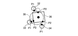
図4は、オブジェクト36と手31との接触モードを説明する図である。本実施形態にかかる画像処理装置1は、接触モードに応じて手31および指とオブジェクト36との間の相互作用にかかるパラメータを変更することにより、ユーザの意図にあわせた直観的な操作を可能にしている。接触モードはTouchモードと、Fricモードと、Fixモードとの3種類である。Touchモードでは、オブジェクト36に接する指の数が1本のみ(one finger)である。Fricモードでは、その指の数が2本(two fingers)または3本以上(three fingers)である。Fixモードは、その指の数が3本以上(power grasp)である。その指の数が3本以上の場合、オブジェクト36と指との重なりの大きさに基づいて、Fricモードと、Fixモードとのいずれかが選択される。
FIG. 4 is a diagram illustrating a contact mode between the
Touchモードはユーザがオブジェクト36に触ろうとしている状態に相当し、Fricモードはユーザがオブジェクト36を挟むまたは軽くつかむ状態に相当する。そして、Fixモードは、ユーザがオブジェクト36をしっかりとつかむ状態に相当する。TouchモードとFricモードとでは、オブジェクト36には、オブジェクト36と指との接触点Pから力がかけられる。またTouchモードとFricモードとで互いに異なる相互作用パラメータが設定される。相互作用パラメータの詳細は後述する。一方、Fixモードではオブジェクト36はユーザの手31に固定される。より具体的には、Fixモードでは画像処理装置1は、オブジェクト36の固定点Jとユーザの手31との相対速度が0になるように仮想空間内のオブジェクト36および手31を動かす。
The Touch mode corresponds to a state where the user is about to touch the
図5は、仮想空間における第1の指32の位置と、接触指42の位置との関係の一例を示す図である。本実施形態にかかる画像処理装置1では、第1の指32が仮想空間内でオブジェクト36に重なることを許容している。ここでいう第1の指32の位置や向きは、モーションキャプチャ16により取得される実空間の指の位置や向きが仮想空間に変換されたものである。また接触指42は、第1の指32の位置をオブジェクト36の表面に接するように移動させたものであり、接触指42とオブジェクト36との接触点Pが第1の指32とオブジェクト36との相互作用の計算に用いられる。なお、本実施形態の説明に用いられる図では、説明の容易のために接触指42を第1の指32等と記載する場合がある。
FIG. 5 is a diagram illustrating an example of a relationship between the position of the
また、第1の指32とオブジェクト36との重なりの大きさが相互作用の算出(例えば第1の指32とオブジェクト36との間の摩擦力の算出)に用いられる。重なりの度合いは、例えば、第1の指32における接触点PRのオブジェクト36の表面からの深さDであってもよいし、現在の指の角度と後述のロック角度との差であってもよい。ここで、接触点PRは第1の指32の表面にあり、かつ、接触指42を基準とした接触点Pの相対位置と、第1の指32を基準とした接触点PRの相対位置は同じである。この処理の詳細については後述する。なお、第2の指33や第3の指34についても第1の指32と同様である。
The size of the overlap between the
以下では画像処理装置1が実現する機能および処理をより詳細に説明する。図6は、画像処理装置1が実現する機能を示すブロック図である。画像処理装置1は機能的に、実動作取得部51、接触検出部52、パラメータ決定部53、物理計算部54、画像描画部55を含む。実動作取得部51は、主に、プロセッサ11が記憶部12に記憶されるプログラムを実行し、入力部14を介してモーションキャプチャ16からの情報を取得し、その情報を処理し、処理結果を記憶部12に格納することにより実現される。接触検出部52、パラメータ決定部53、物理計算部54は、主に、プロセッサ11が記憶部12に記憶されるプログラムを実行し、記憶部12等に格納された情報を処理し、処理結果を記憶部12に格納することにより実現される。画像描画部55は、主に、プロセッサ11が記憶部12に記憶されるプログラムを実行し、記憶部12等に格納された情報を処理し、表示出力デバイスが画像を表示するよう表示制御部15を制御することにより実現される。
Hereinafter, functions and processes realized by the image processing apparatus 1 will be described in more detail. FIG. 6 is a block diagram illustrating functions realized by the image processing apparatus 1. The image processing apparatus 1 functionally includes an actual
実動作取得部51は、モーションキャプチャ16からの信号に基づいて、手21の動きを取得し、手21の動きの情報を記憶部12に格納する。手21の動きには、その手21の指の曲げ伸ばしを示す操作も含まれる。なお、実動作取得部51は、手21の動きとして、実在する手21の指そのものと異なるものの動きを取得してもよく、例えば実動作取得部51は、コントローラの位置から手21の位置を取得し、コントローラのボタンやトリガの操作から指の曲げ伸ばしを示す操作を取得してもよい。
The actual
接触検出部52は、実動作取得部51により取得された手21の動きに基づいて、仮想空間における、指とオブジェクト36との接触を検出する。なお、接触検出部52は、指とオブジェクト36との接触が検出されてからの指の移動量が所定の閾値を超えた場合には、指とオブジェクト36とが重なっても指とオブジェクト36とが接触していないものとして扱い、接触を検出しない。
The
パラメータ決定部53は、検出された接触に基づいて仮想空間内においてオブジェクト36に接触する指の数を検出し、その検出された指の数に基づいて指とオブジェクト36との間の相互作用を求めるための相互作用パラメータを決定する。また、相互作用パラメータは摩擦にかかる摩擦パラメータを含み、摩擦パラメータは、指の数に応じて定まる摩擦係数と、指とオブジェクト36との重なりの大きさとに基づいて算出される。また、パラメータ決定部53は、オブジェクト36と指との接触が検出されてからの手21の指の曲げを示す操作の量にさらに基づいてオブジェクト36と指が属する手との相対位置を固定する拘束条件を設定するか、オブジェクト36と指との間に摩擦力を働かせるかを選択する。また、パラメータ決定部53は、指が属する手31とオブジェクト36との間を拘束する拘束条件であって相互作用パラメータに応じた拘束条件を決定する。
The
物理計算部54は、決定された相互作用パラメータや拘束条件に基づいて、オブジェクト36の動きを計算する。物理計算部54は、オブジェクト36の動きを、物理法則をシミュレートする手順に従って計算する。
The
画像描画部55は、計算されたオブジェクト36の動きに基づいて、オブジェクト36の3次元画像を描画する。
The
図7は、画像処理装置1が実行する処理の一例を示すフロー図である。図7に示す処理は、フレーム(そのフレームの期間が経過する)ごとに繰り返し実行される。以下では処理のフローとともに各機能の処理の詳細について説明する。はじめに、実動作取得部51は、プロセッサ11の動作により、モーションキャプチャ16がキャプチャした実空間の手21の位置、手21の向き、指の角度などを入力部14を介して取得し、手21の位置、手21の向き、指の角度などの情報を記憶部12に格納する(ステップS101)。例えば、取得された指の角度の変化は、指の曲げ伸ばしを示す操作に相当する。なお、実動作取得部51はコントローラのトリガ等の操作量に応じて指の角度を算出してもよい。
FIG. 7 is a flowchart illustrating an example of a process executed by the image processing apparatus 1. The process shown in FIG. 7 is repeatedly executed for each frame (the period of the frame elapses). Hereinafter, the details of the processing of each function will be described together with the processing flow. First, the real
次に、接触検出部52は、仮想空間内において接触判定に用いる(判定用の)複数の指の位置を決定する(ステップS102)。判定用の複数の指の位置は、例えば実空間における手21の指の位置が座標変換されることにより生成される、仮想空間の座標系における指の位置である。図8は、実空間に相当する指の角度と、接触判定に用いる指の角度との関係の一例を示す図である。接触検出部52は、前回のフレームにおいて指(例えば第1の指32)とオブジェクト36との接触が検出されている場合には、指の角度がその接触がはじめて検出されたフレームにおける角度(以下では「ロック角度」という)より大きくならないように指の角度を設定する。図8の例では、取得された第1の指322の角度が、その接触がはじめて検出されたフレームにおける第1の指321のロック角度以上であれば、接触の判定に用いる指の角度はロック角度となる。また、取得された第1の指323の角度がロック角度以下であれば、接触の判定に用いる指の角度は取得された指の角度になる。なお、このロック角度を用いた処理は行われなくてもよいが、この処理により、ユーザがより快適にオブジェクト36を操作することが可能になる。
Next, the
また、接触検出部52は、接触判定に用いる複数の指の位置に基づいて、仮想空間内の複数の指とオブジェクト36との接触を検出する(ステップS103)。図9は、接触検出部52の処理を示すフロー図である。図9は、特にステップS103の処理の詳細を示すフローである。
Further, the
ステップS103の処理において、接触検出部52は、はじめに、新たな1つの指を接触判定の対象の指とする(ステップS301)。そして、接触検出部52は、判定用の手の位置、向き、指の角度に基づいて、仮想空間内の接触判定領域37を生成する(ステップS302)。
In the process of step S103, the
図10は接触判定領域37の一例を示す図である。図10には、第1の指32について生成される接触判定領域37が示されている。接触判定領域37は、第1の指32などの指のうち指先に近い部分の外側に生成されるものであり、図10の例では、接触判定領域37は指先に相当するカプセルの表面とオブジェクト36との間にあり、指先に相当するカプセルに対して一定の間隔を有する。以下では、接触判定領域37とオブジェクト36との接触が検出されることを、第1の指32、第2の指33、第3の指34といった指とオブジェクト36とが重なるとも表現する。
FIG. 10 is a diagram illustrating an example of the
次に、接触検出部52は、生成された接触判定領域37と複数のオブジェクト36のいずれかとの接触を検出する(ステップS303)。接触判定領域37といずれかのオブジェクト36との接触が検出された場合には(ステップS303のY)、ステップS304以降の処理を行い、接触が検出されなかった場合には(ステップS303のN)、ステップS304以降の処理をスキップし、ステップS309の処理に遷移する。
Next, the
ステップS304からステップS308にかかる処理では、接触判定の対象の指とそのオブジェクト36との過去の接触の状況に基づいて、今回の接触を有効とするか否かを判定している。ステップS304では、接触検出部52は前回のフレームにおけるその指と、接触が検出されたオブジェクト36との接触判定の結果(後述の前回の接触データと同じであってよい)を取得する。
In the processing from step S304 to step S308, it is determined whether or not the current contact is valid based on the state of the past contact between the finger as the contact determination target and the
そして、前回のフレームにおいてその指とそのオブジェクト36との接触が検出されている場合には(ステップS305のY)、指の表面にある第1接触点P1と、はじめに接触した際の第2接触点P2との距離L1が閾値以下であるかを判定する(ステップS306)。指を基準とした第1接触点P1の相対位置は、指とそのオブジェクト36との接触がはじめて検出されたタイミングにおける接触指42とオブジェクト36との第2接触点P2の相対位置と同じである。ここで、この距離L1は指とオブジェクト36との接触が検出されてからの指の移動量に相当する。なお、第2接触点P2として、オブジェクト36側の接触点を用いてもよい。この場合、オブジェクト36を基準とした第2接触点P2の相対位置は、指とそのオブジェクト36との接触がはじめて検出されたタイミングにおける接触指42とオブジェクト36との接触点Pの相対位置と同じである。
Then, when the contact between the finger and the
図11は、第1接触点P1と第2接触点P2との距離L1の計算を説明する図である。例えば第1の指32がオブジェクト36とはじめて接した際には、第1接触点P1と第2接触点P2とはほぼ同じ位置にある。一方、いくつかのフレームの処理が経過した後には、第1の指32の位置等の変化により、第1接触点P1と第2接触点P2とが離れる場合がある。接触検出部52は、この第1接触点P1と第2接触点P2との距離L1を算出する。なお、図11の例では、第1の指32がオブジェクト36から離れているが、この例では接触判定領域37とオブジェクト36との接触が検出されている。また、第1の指32とオブジェクト36とが重なっていても、距離L1の検出は同じ方法で行われてよい。
FIG. 11 is a diagram illustrating the calculation of the distance L1 between the first contact point P1 and the second contact point P2. For example, when the
図12は、接触点Pの算出方法を説明する図である。図11の例では、判定用の指326からオブジェクト36の表面を構成する面SAに接触する接触指42を求め、その接触指42とオブジェクト36の表面との接触点Pを求める例を示している。接触検出部52は、接触点Pの算出において、オブジェクト36を構成する面のうち、接触指42を求めるために用いる1または複数の面SAを決定する。この面SAは、オブジェクト36と接触判定領域37との接触を検出する際に用いられる面と同じであるので決定の詳細については省略する。次に、接触検出部52は、接触指42がその決定された面の上に存在し、さらに接触指42と判定用の指326との距離L2が最小になる条件を満たすように、接触指42の位置を算出する。この算出方法は、いわゆるGod Objectを実空間の指の位置が変換された指の位置から求める方法と同様のものである。
FIG. 12 is a diagram illustrating a method of calculating the contact point P. In the example of FIG. 11, an example is shown in which the
そして、第1接触点P1と第2接触点P2との距離L1が判定閾値以下の場合には(ステップS306のY)、接触検出部52は接触が有効であると決定し、今回のフレームにおける接触データとして、前回の接触データを設定する(ステップS307)。一方、第1接触点P1と第2接触点P2との距離L1が判定閾値より大きい場合には(ステップS306のN)、接触が無効であると判定し、ステップS309の処理へ遷移する。
When the distance L1 between the first contact point P1 and the second contact point P2 is equal to or smaller than the determination threshold (Y in step S306), the
また、ステップS305において、前回のフレームにおいてその指とそのオブジェクト36との接触が検出されていない場合には、接触検出部52は接触を有効と判断し、ステップS306、S307の処理をスキップし、ステップS308の処理へ遷移する。
Also, in step S305, when the contact between the finger and the
ステップS308においては、接触検出部52は対象の指といずれかのオブジェクト36との接触が有効であることを示す接触データであって今回のフレームにおける接触データをメモリに保存する。接触データは指ごとに存在し、1つの接触データは、指を識別する指ID、接触の有無、接触するオブジェクト36の物体ID、接触点Pの座標、接触点Pにおけるオブジェクト36の表面の法線を含む。なおステップS306,S307の処理により、指が同じオブジェクト36に接触し続けている場合には、接触データには、その指とオブジェクト36とがはじめに接触した時点の情報が格納される。
In step S308, the
ステップS308等の処理により、ユーザの指の動きにぶれがあることに起因して接触点Pが変化するためにオブジェクト36の動きが不安定になる現象を防ぐことができる。また、ステップS306により指のぶれでない移動の場合に接触点Pが変化せずにオブジェクト36の動きが不自然になることを防ぐこともできる。
By the processing in step S308 and the like, it is possible to prevent a phenomenon that the movement of the
そして、ステップS309においては、すべての指を接触判定の処理の対象としたかを判定し(ステップS309)、すべての指を接触判定の対象として処理をしていない場合には(ステップS309のN)、ステップS301の処理へ戻り、すべての指を接触判定の対象として処理をした場合には(ステップS309のY)、ステップS103の処理を終了する。 Then, in step S309, it is determined whether all the fingers have been subjected to the contact determination processing (step S309). If not all the fingers have been subjected to the contact determination processing (N in step S309) ), The process returns to step S301, and when the process is performed with all the fingers as targets of contact determination (Y in step S309), the process in step S103 ends.
仮想空間内の複数の指とオブジェクト36との接触が判定されると、パラメータ決定部53は、過去の接触と現在の接触との少なくとも一方に基づいて、指と物体との間の相互作用に関するパラメータを決定する(ステップS104)。この相互作用に関するパラメータは、指とオブジェクト36との間の摩擦力や、指とオブジェクト36との間の拘束条件の種類を含む。以下ではステップS104の処理についてさらに詳細に説明する。
When the contact between the plurality of fingers in the virtual space and the
図13は、パラメータ決定部53の処理を示すフロー図である。図13に示される処理は、前回のフレームにおいて手31の指とオブジェクト36との関係がFixモードであり、かつ、接触検出部52が3本以上の指とオブジェクト36との接触を検出していない場合にも、予め定められた条件を満たすことを条件にFixモードを維持させる処理である。この予め定められた条件は、ユーザがオブジェクト36を掴み続ける意思を持っていると推定される条件であり、詳細は後述する。
FIG. 13 is a flowchart showing the processing of the
はじめに、パラメータ決定部53は、前回のフレームにおける手または指とオブジェクト36との接触モードを取得し、指と接触しかつその接触モードがFixモードであるオブジェクト36が存在するかを判定する(ステップS401)。接触モードがFixモードであるオブジェクト36が存在しない場合は(ステップS401のN)、図13に示される以降の処理はスキップされる。
First, the
接触モードがFixモードであるオブジェクト36が存在する場合には(ステップS401のY)、パラメータ決定部53は前回のフレームにおいてそのオブジェクト36に接触している指を取得する(ステップS402)。パラメータ決定部53は、その取得された指のうち、現在の角度が、(ロックされている角度−0.1(rad))より大きい指があるか判定する(ステップS404)。ロックされている角度は、オブジェクト36に初めて接触したときの角度である。なお、この角度の条件を満たす指がない場合には(ステップS404のN)、パラメータ決定部53は、ユーザが物体を掴む意思がないものとして、図13の処理を終了する。なお、ロックされている角度から減算される0.1radの値は、指の動きのブレを考慮して適宜変更されてよい。
When there is an
一方、この角度の条件を満たす指がある場合には(ステップS404のY)、パラメータ決定部53はステップS406以降に示される別の手法でFixモードを維持するか否かを判定する。ステップS406では、パラメータ決定部53は、前回のフレームにおいてオブジェクト36に有効に接触する複数の指の側の接触点Pの現在の位置に基づいて、オブジェクト36と手31との接触を判定するための領域である掴みトリガ38を生成する(ステップS406)。
On the other hand, if there is a finger that satisfies the angle condition (Y in step S404), the
図14は、掴みトリガ38の一例を示す図である。掴みトリガ38は、例えば、第1の指32から第3の指34の表面の接触点の現在の位置(第1接触点P1の位置)に基づいて生成されてよく、掴みトリガ38は第1接触点P1の位置の重心を中心とした球であってよい。
FIG. 14 is a diagram illustrating an example of the gripping trigger 38. The gripping trigger 38 may be generated, for example, based on the current position of the contact point on the surface of the
そして、掴みトリガ38とオブジェクト36との接触が検出された場合には(ステップS407のY)、パラメータ決定部53は、Fixモードを維持することを決定し、ステップS409の処理へ遷移させる。掴みトリガ38とオブジェクト36との接触が検出されない場合には(ステップS407のN)、図13の処理を終了する。
Then, when the contact between the grasping trigger 38 and the
ステップS409では、前回のフレームでオブジェクト36と有効に接触していた指と、そのオブジェクト36との接触を有効にし、それらの指の前回のフレームにおける接触データを今回の接触データに設定する。
In step S409, the contact between the finger that has effectively contacted the
図15は、パラメータ決定部53の処理を示すフロー図である。図15に示す処理は、図13に示される処理の後に実行される。図15に示される処理は、オブジェクト36との接触が有効とされた指の数に基づいて指とオブジェクト36との接触モードを決定し、その接触モードおよび接触モードの変化に応じて相互作用パラメータを決定する処理である。この処理は、オブジェクト36ごとに実行されてよい。また、手31の指が複数のオブジェクト36の組をまとめて挟む場合には、そのオブジェクト36の組についてこの処理が実行されてもよい。
FIG. 15 is a flowchart showing the processing of the
図13に示される処理が実行されると、パラメータ決定部53は、オブジェクト36に接触する指の数をカウントする(ステップS451)。オブジェクト36に接触する指の数は、図15の例では、接触検出部52によりそのオブジェクト36との接触が有効であると判定された指の数である。より具体的には、パラメータ決定部53は、現在の接触データから、オブジェクト36ごとに、そのオブジェクト36の物体IDを有する接触データの数をカウントする。そして、パラメータ決定部53は、その接触データの数に基づいて、そのオブジェクト36ごとに現在の物体接触データをオブジェクト36に関連付けて記憶させる(ステップS452)。物体接触データは、オブジェクト36を識別する物体IDとそのオブジェクト36に接触する指の数と、その接触している指の指IDとを含む。
When the processing illustrated in FIG. 13 is executed, the
次にパラメータ決定部53は、前回のフレームの物体接触データに基づいて、前回のフレームにおけるオブジェクト36に接触する指の数と接触モードとを取得する(ステップS453)。パラメータ決定部53は、物体接触データに保存されるオブジェクト36に接触する指の数と接触モードとを取得してもよいし、後述のステップS456からステップS463に対応する処理を前回のフレームの物体接触データを用いて実行することで前回のフレームにおけるオブジェクト36に接触する指の数と接触モードとを取得してもよい。
Next, based on the object contact data of the previous frame, the
次に、パラメータ決定部53は、オブジェクト36に接触する指の数を判定する(ステップS454)。
Next, the
そして、オブジェクト36に接触する指の数が1未満の場合には(ステップS454のN)、パラメータ決定部53は接触がなくなったものとして、指とオブジェクト36との拘束をリセットし(ステップS455)、図15の処理を終了する。より具体的には、パラメータ決定部53は指とオブジェクト36との拘束条件を削除する。またパラメータ決定部53は、指に接触する他のオブジェクト36がない場合には、さらに接触検出部52のステップS102の処理で用いるロック角度の設定も削除する。ロック角度の削除により、次に指とオブジェクト36とが接触するまで接触判定に用いる指の角度が自由に変化する。
If the number of fingers that contact the
一方、オブジェクト36に接触する指の数が1以上の場合には(ステップS454のY)、パラメータ決定部53は、そのオブジェクト36に接触する現在の指の数が前回のフレームにおける指の数と異なるか否かを判定する(ステップS456)。現在の指の数が前回の指の数と異なる場合には(ステップS456のY)、パラメータ決定部53は現在の指の数に応じて接触モードを選択する(ステップS457)。より具体的には、パラメータ決定部53は、接触モードとして、指の数が1の場合はTouchモード、指の数が2または3以上の場合にはFricモードを選択する。
On the other hand, when the number of fingers touching the
ステップS456において、現在の指の数と前回の指の数が同じ場合には(ステップS456のN)、パラメータ決定部53は現在オブジェクト36に接触する指の数が3未満か否か判定する(ステップS458)。接触する指の数が3未満の場合には(ステップS458のY)、パラメータ決定部53は前回の接触モードを継続し、拘束条件の多くとも一部を更新する(ステップS459)。拘束条件の詳細については後述する。
If the current number of fingers and the previous number of fingers are the same in step S456 (N in step S456), the
一方、接触する指の数が3以上の場合には(ステップS458のN)、パラメータ決定部53はさらにオブジェクト36と指との重なりの大きさに基づいて、接触モードを決定する。より具体的には、パラメータ決定部53は現在の指の角度が握りこみ状態へ変化した場合には(ステップS460のY)、接触モードとしてFixモードを選択し(ステップS461)、現在の指の角度が握りこみ状態から変化した場合には(ステップS462のY)、接触モードとしてFricモードを選択する。また、現在の指の角度が握りこみ状態へ変化せず、また握りこみ状態からも変化しない場合(ステップS462のN)、パラメータ決定部53は接触モードを変化させず、ステップS459へ移る。
On the other hand, when the number of fingers to be touched is three or more (N in step S458), the
握りこみ状態は、オブジェクト36と指との重なりの大きさがある基準より大きい状態である。より具体的には、ロック角度からの指の角度の変化量(変化角Ac)が閾値より大きい状態である。ロック角度はオブジェクト36と指との接触が検出された際の角度であるので、変化角Acは、ロック角度はオブジェクト36と指との接触が検出されてからの操作による指の角度の変化量である。図16は、Fixモードの判定手法を説明する図である。図16における第1の指322は現在の位置にある。一方、第1の指321はオブジェクト36との接触が検知された際の位置にあり、その角度はロック角度である。パラメータ決定部53は、現在の第1の指322の角度とロック角度との間の変化角Acが、角度閾値Atより大きい場合を握りこみ状態であると決定する。言い換えれば、パラメータ決定部53は、変化角Acが角度閾値At以下から角度閾値Atを超える値に変化した場合には、握りこみ状態へ変化したと判定し、変化角Acが角度閾値Atを超える値から角度閾値At以下へに変化した場合には、握りこみ状態から変化したと判定する。
The gripping state is a state where the size of the overlap between the
ステップS457において新たに接触モードが決定されると、パラメータ決定部53は手31とオブジェクト36との拘束条件を新たに設定する(ステップS464)。なお、ステップS464において、接触モードがTouchモードおよびFricモードの場合には、オブジェクト36に接触する指の現在の角度をロック角度として保存することで指の角度をロックする。一方、Fixモードの場合は、Fricモードに変更される際に設定されたロック角度を変更しない。
When a new contact mode is determined in step S457, the
接触モードがTouchモードまたはFricモードの場合には、拘束条件はオブジェクト36の表面の接触点Pを介してかかる摩擦力等を表現する条件である。図17は、オブジェクト36の拘束の要素を説明する図であり、特に接触モードがTouchモードまたはFricモードの場合に指とオブジェクト36との間で拘束する要素を示す図である。図17に示される摩擦視錐台46は、接触点Pにおいて、第1の指32とオブジェクト36との間に摩擦が生じていることを示している。また、図17におけるY軸はオブジェクト36の表面の法線と同じ向きである。X軸およびZ軸はその法線と直交する向きであり、X軸およびZ軸は互いに直交する。図17のTwistは、その法線を軸としてねじれるように回転する成分を示し、Swingは接触点Pを通りその法線と直交する線を軸として回転する成分を示す。
When the contact mode is the Touch mode or the Fric mode, the constraint condition is a condition expressing the frictional force or the like applied via the contact point P on the surface of the
図18は、オブジェクト36の拘束の要素に応じた拘束の手法を示す図である。X軸およびZ軸方向の位置の移動については、例えば、第1の指32の側の第1接触点P1と、オブジェクト36側の第2接触点P2との相対速度が最小になるようにオブジェクト36および第1の指32に力をかけるいわゆる固定ジョイントを設定する。ここで、摩擦を表現するために、この固定ジョイントによりオブジェクト36および第1の指32にかかる力は静止最大摩擦力または動最大摩擦力を上限としている。一方、Z軸方向の位置の移動については、第1の指32とオブジェクト36とが反発しめり込まないように制限する拘束条件となっている。TwistおよびSwingの成分については、回転する角度を実際の数分の一にするなどの調整をしている。パラメータ決定部53は、接触モードがTouchモードまたはFricモードの場合には、接触する各指についてこれらの要素について拘束条件を決定する。
FIG. 18 is a diagram showing a constraint method according to the constraint element of the
ここで、パラメータ決定部53は、接触モードがTouchモードであるかFricモードであるかに応じて静止摩擦係数(または動摩擦係数)を設定する。より具体的には、Touchモードにおける静止摩擦係数(または動摩擦係数)が、Fricモードにおけるものより小さくなるように設定される。また、パラメータ決定部53は、指とオブジェクト36との重なりの大きさと、その静止摩擦係数(または動摩擦係数)とに基づいて最大静止摩擦力(または最大動摩擦力)を算出する。指とオブジェクト36との重なりの大きさは、例えば、指の第1接触点P1のオブジェクト36の表面からの深さD(図5参照)である。これにより、ユーザがオブジェクト36を触ることを意図していると推定されるTouchモードで物体が必要以上に動くことを抑止し、ユーザがオブジェクト36を挟もうとしていると推定されるFricモードでオブジェクト36が滑ってしまう現象を防ぐことができる。これにより、直観的な操作を可能にする。なお、ステップS459においては、パラメータ決定部53は、静止摩擦係数(または動摩擦係数)は変更せず、指とオブジェクト36との重なりの大きさと、その静止摩擦係数(または動摩擦係数)とに基づいて最大静止摩擦力(または最大動摩擦力)を算出する。
Here, the
図15に示される処理では、オブジェクト36に接触する指の本数が同じであっても、オブジェクト36と指との重なりの大きさによってFricモードとするかFixモードにするかを選択している。これにより、例えばものを投げる際に、オブジェクト36が手31から離れていく動作をより自然に再現できる。また、単に手31がオブジェクト36を離す際のオブジェクト36の動きも、より自然に再現することができる。なお、パラメータ決定部53は、指の本数と、指とオブジェクト36の重なりの大きさではなく、オブジェクト36の互いに反対の側に指が存在するか否かと、重なりの大きさとに基づいて、FricモードとするかFixモードにするかを選択してもよい。
In the processing shown in FIG. 15, even if the number of fingers that touch the
ここまでの説明では、X軸およびZ軸方向の位置の移動について、指とオブジェクト36とを拘束する固定ジョイントを設定しているが、代わりに、パラメータ決定部53は手31を代表する代表点PHと、オブジェクト36上の第2接触点P2との間で固定ジョイントを設定してもよい。この場合、パラメータ決定部53は代表点PHと、オブジェクト36側の第2接触点P2との相対速度が最小になるようにオブジェクト36および代表点PHに力をかける。したがって代表点PHと第2接触点P2との相対位置が保存される。代表点PHは、例えば指の付け根や掌の中央に相当し、手31の位置を代表する位置である。
In the description so far, a fixed joint that restricts the finger and the
図19および20は、オブジェクト36と仮想の手31との関係を説明する図である。第1の指32や第2の指33などの指は、その位置がぶれやすい。例えば、図19に示すようにオブジェクト36と接触していても、手31の移動などにより位置がぶれてしまい(図20参照)、固定ジョイントを介してオブジェクト36の動きをぶれさせてしまう。そこで、仮想の手31とオブジェクト36とを固定ジョイントを介して拘束することにより、そのぶれによる影響を軽減することが可能になる。なお、拘束によりに生じる力はオブジェクト36の表面にある第2接触点P2にかかる。
FIGS. 19 and 20 are diagrams illustrating the relationship between the
接触モードがFixモードの場合には、パラメータ決定部53は、拘束条件として、オブジェクト36と指との接触点Pであってオブジェクト36の表面にある複数の接触点Pの重心と、代表点PHの位置との相対速度を0とする条件を決定する。こちらについてはユーザが掴む操作をしていると推定されるので、接触点Pを介した摩擦力をかける必要性が低く、より単純な計算で直観的な操作を実現することができる。
When the contact mode is the Fix mode, the
ここで、ステップS457において現在の接触モードが前回の接触モードと同じ場合には(ステップS457のN)、パラメータ決定部53は接触モードに応じて拘束条件の多くとも一部を更新する(ステップS459)。より具体的には、接触モードがTouchモードまたはFricモードの場合には、指とオブジェクト36との重なりの大きさに基づいて、最大静止摩擦力または最大動摩擦力を更新する。接触モードが遷移したか否かに応じて処理を異ならせることで、処理量を削減したり、不安定な動きを防止することが可能になる。
Here, if the current contact mode is the same as the previous contact mode in step S457 (N in step S457), the
このように、オブジェクト36に接触する指の本数といった状況に応じてオブジェクト36と手31や指との相互作用を示すパラメータ(拘束条件や摩擦係数など)を変化させることで、ユーザがオブジェクト36を直観的に操作することが可能になる。
In this way, the user changes the parameter (restriction condition, coefficient of friction, etc.) indicating the interaction between the
Claims (6)
仮想空間における、前記指と物体との接触を検出する接触検出手段と、
前記物体と前記指との接触が検出されてからの前記手の指の曲げを示す操作の量に基づいて、前記物体と前記指が属する手との相対位置を固定する拘束条件を設定するか、前記物体と前記指との間に摩擦力を働かせるかを選択する選択手段と、
前記選択に基づいて、前記物体の動きを計算する計算手段と、
前記動きが計算された物体を描画する描画手段と、
を含む画像処理装置。Acquisition means for acquiring an operation indicating bending of a finger of a hand,
Contact detection means for detecting contact between the finger and an object in a virtual space;
Whether to set a constraint condition that fixes a relative position between the object and the hand to which the finger belongs based on the amount of operation indicating bending of the finger of the hand after the contact between the object and the finger is detected. Selecting means for selecting whether to exert a frictional force between the object and the finger,
Calculating means for calculating the motion of the object based on the selection;
Drawing means for drawing an object whose motion has been calculated;
An image processing apparatus including:
前記選択手段は、前記物体に接触する指の数が3以上の場合に、前記物体と前記指との接触が検出されてからの前記手の指の曲げを示す操作の量に基づいて、前記物体と前記指が属する手との相対位置を固定する拘束条件を設定するか、前記物体と前記指との間に摩擦力を働かせるかを選択する、
画像処理装置。The image processing apparatus according to claim 1,
The selection means, when the number of fingers in contact with the object is 3 or more, based on the amount of operation indicating the bending of the finger of the hand since the contact between the object and the finger is detected, To set a constraint condition to fix the relative position of the object and the hand to which the finger belongs, or to select whether to apply a frictional force between the object and the finger,
Image processing device.
前記選択手段は、前記物体に接触する指の数が2以下の場合に、前記数に応じて前記物体と前記指との間の摩擦係数を設定する、
画像処理装置。The image processing apparatus according to claim 2,
When the number of fingers that contact the object is two or less, the selection unit sets a coefficient of friction between the object and the finger according to the number.
Image processing device.
前記選択手段は、前記物体と前記指との接触が検出されてからの前記操作が示す指の角度の変化量に基づいて、前記物体と前記指が属する手との相対位置を固定する拘束条件を設定するか、前記物体と前記指との間に摩擦力を働かせるかを選択する、
画像処理装置。The image processing apparatus according to claim 1,
The selecting means is configured to fix a relative position between the object and the hand to which the finger belongs based on a change in the angle of the finger indicated by the operation after the contact between the object and the finger is detected. Set or select whether to exert a frictional force between the object and the finger,
Image processing device.
仮想空間における、前記指と物体との接触を検出するステップと、
前記物体と前記指との接触が検出されてからの前記手の指の曲げを示す操作の量に基づいて、前記物体と前記指が属する手との相対位置を固定する拘束条件を設定するか、前記物体と前記指との間に摩擦力を働かせるかを選択するステップと、
前記選択に基づいて、前記物体の動きを計算するステップと、
前記動きが計算された物体を描画するステップと、
を含む画像処理方法。Obtaining an operation indicating bending of the finger of the hand;
Detecting contact between the finger and an object in a virtual space;
Whether to set a constraint condition that fixes a relative position between the object and the hand to which the finger belongs based on an amount of operation indicating bending of the finger of the hand after the contact between the object and the finger is detected. Selecting whether to exert a frictional force between the object and the finger,
Calculating the motion of the object based on the selection;
Drawing the object whose motion has been calculated;
An image processing method including:
仮想空間における、前記指と物体との接触を検出する接触検出手段、
前記物体と前記指との接触が検出されてからの前記手の指の曲げを示す操作の量に基づいて、前記物体と前記指が属する手との相対位置を固定する拘束条件を設定するか、前記物体と前記指との間に摩擦力を働かせるかを選択する選択手段、
前記選択に基づいて、前記物体の動きを計算する計算手段、および、
前記動きが計算された物体を描画する描画手段、
としてコンピュータを機能させるためのプログラム。Acquisition means for acquiring an operation indicating bending of a finger of a hand,
Contact detection means for detecting contact between the finger and an object in a virtual space,
Whether to set a constraint condition that fixes a relative position between the object and the hand to which the finger belongs based on an amount of operation indicating bending of the finger of the hand after the contact between the object and the finger is detected. Selecting means for selecting whether to exert a frictional force between the object and the finger,
Calculating means for calculating the motion of the object based on the selection; and
Drawing means for drawing the object whose motion has been calculated,
Program to make a computer function as a computer.
Applications Claiming Priority (3)
| Application Number | Priority Date | Filing Date | Title |
|---|---|---|---|
| JP2017207361 | 2017-10-26 | ||
| JP2017207361 | 2017-10-26 | ||
| PCT/JP2018/039227 WO2019082853A1 (en) | 2017-10-26 | 2018-10-22 | Image processing device, image processing method, and program |
Publications (2)
| Publication Number | Publication Date |
|---|---|
| JPWO2019082853A1 true JPWO2019082853A1 (en) | 2020-04-02 |
| JP6874149B2 JP6874149B2 (en) | 2021-05-19 |
Family
ID=66246562
Family Applications (1)
| Application Number | Title | Priority Date | Filing Date |
|---|---|---|---|
| JP2019551128A Active JP6874149B2 (en) | 2017-10-26 | 2018-10-22 | Image processing equipment, image processing methods and programs |
Country Status (3)
| Country | Link |
|---|---|
| US (1) | US11181972B2 (en) |
| JP (1) | JP6874149B2 (en) |
| WO (1) | WO2019082853A1 (en) |
Families Citing this family (4)
| Publication number | Priority date | Publication date | Assignee | Title |
|---|---|---|---|---|
| US9696795B2 (en) * | 2015-02-13 | 2017-07-04 | Leap Motion, Inc. | Systems and methods of creating a realistic grab experience in virtual reality/augmented reality environments |
| DE102020121937A1 (en) | 2020-08-21 | 2022-02-24 | Ford Global Technologies, Llc | Method for the computer-implemented simulation of a virtual hand |
| WO2023281819A1 (en) * | 2021-07-08 | 2023-01-12 | ソニーグループ株式会社 | Information processing device for determining retention of object |
| CN120051749A (en) * | 2022-10-24 | 2025-05-27 | 索尼集团公司 | Information processing apparatus and information processing method |
Family Cites Families (11)
| Publication number | Priority date | Publication date | Assignee | Title |
|---|---|---|---|---|
| JP3301096B2 (en) * | 1991-12-19 | 2002-07-15 | 日本電気株式会社 | Object gripping method |
| JP3585498B2 (en) * | 1994-07-19 | 2004-11-04 | 純次 古荘 | Virtual and remote reality systems |
| US7050955B1 (en) * | 1999-10-01 | 2006-05-23 | Immersion Corporation | System, method and data structure for simulated interaction with graphical objects |
| US10168873B1 (en) * | 2013-10-29 | 2019-01-01 | Leap Motion, Inc. | Virtual interactions for machine control |
| JP2017182532A (en) | 2016-03-31 | 2017-10-05 | ソニー株式会社 | Information processing apparatus, display control method, and program |
| EP3467792B1 (en) * | 2016-05-25 | 2024-04-24 | Sony Interactive Entertainment Inc. | Image processing apparatus, image processing method, and program |
| JP6710285B2 (en) * | 2016-10-28 | 2020-06-17 | 株式会社ソニー・インタラクティブエンタテインメント | Information processing apparatus, control method, program, and storage medium |
| US10996814B2 (en) * | 2016-11-29 | 2021-05-04 | Real View Imaging Ltd. | Tactile feedback in a display system |
| US11385759B2 (en) * | 2017-12-19 | 2022-07-12 | Sony Interactive Entertainment Inc. | Information processing apparatus, information processing method, and program |
| US11875012B2 (en) * | 2018-05-25 | 2024-01-16 | Ultrahaptics IP Two Limited | Throwable interface for augmented reality and virtual reality environments |
| US10884487B2 (en) * | 2019-03-21 | 2021-01-05 | Microsoft Technology Licensing, Llc | Position based energy minimizing function |
-
2018
- 2018-10-22 WO PCT/JP2018/039227 patent/WO2019082853A1/en not_active Ceased
- 2018-10-22 JP JP2019551128A patent/JP6874149B2/en active Active
- 2018-10-22 US US16/757,558 patent/US11181972B2/en active Active
Also Published As
| Publication number | Publication date |
|---|---|
| US11181972B2 (en) | 2021-11-23 |
| JP6874149B2 (en) | 2021-05-19 |
| US20210141442A1 (en) | 2021-05-13 |
| WO2019082853A1 (en) | 2019-05-02 |
Similar Documents
| Publication | Publication Date | Title |
|---|---|---|
| JP6563596B2 (en) | Image processing apparatus, image processing method, and program | |
| KR102346294B1 (en) | Method, system and non-transitory computer-readable recording medium for estimating user's gesture from 2d images | |
| CN111913565B (en) | Virtual content control method, device, system, terminal device and storage medium | |
| KR102517425B1 (en) | Systems and methods of direct pointing detection for interaction with a digital device | |
| US10179407B2 (en) | Dynamic multi-sensor and multi-robot interface system | |
| JP6874149B2 (en) | Image processing equipment, image processing methods and programs | |
| JP5213183B2 (en) | Robot control system and robot control program | |
| KR102021851B1 (en) | Method for processing interaction between object and user of virtual reality environment | |
| CN109189302B (en) | Control method and device of AR virtual model | |
| CN104423569A (en) | Pointing position detecting device, method and computer readable recording medium | |
| JP6360509B2 (en) | Information processing program, information processing system, information processing method, and information processing apparatus | |
| CN106445118B (en) | Virtual reality exchange method and device | |
| WO2023173668A1 (en) | Input recognition method in virtual scene, device and storage medium | |
| CN109584148A (en) | A kind of method and apparatus handling two-dimentional interface in VR equipment | |
| CN103716673B (en) | Somatosensory-mode click button control method and system | |
| TW201738722A (en) | Program, computer device, program execution method, and system | |
| CN116136736A (en) | Information processing method, apparatus, electronic device, storage medium, and program product | |
| US11182957B2 (en) | Image processing device, image processing method, and program for suppressing movement of an object in virtual space | |
| JP2012098812A (en) | Human body posture estimation apparatus, human body posture estimation method and computer program | |
| KR101472314B1 (en) | 3D Input Method and Apparatus using Single Camera | |
| CN111427489B (en) | Client window moving method, device and equipment and readable storage medium | |
| CN115088016B (en) | Method and system for implementing dynamic input resolution of vSLAM system | |
| JP2026046724A (en) | Display image generation device and display image generation method | |
| WO2023176034A1 (en) | Control device and control method | |
| CN105787971A (en) | Information processing method and electronic equipment |
Legal Events
| Date | Code | Title | Description |
|---|---|---|---|
| A621 | Written request for application examination |
Free format text: JAPANESE INTERMEDIATE CODE: A621 Effective date: 20191122 |
|
| A131 | Notification of reasons for refusal |
Free format text: JAPANESE INTERMEDIATE CODE: A131 Effective date: 20210126 |
|
| A521 | Request for written amendment filed |
Free format text: JAPANESE INTERMEDIATE CODE: A523 Effective date: 20210324 |
|
| TRDD | Decision of grant or rejection written | ||
| A01 | Written decision to grant a patent or to grant a registration (utility model) |
Free format text: JAPANESE INTERMEDIATE CODE: A01 Effective date: 20210406 |
|
| A61 | First payment of annual fees (during grant procedure) |
Free format text: JAPANESE INTERMEDIATE CODE: A61 Effective date: 20210421 |
|
| R150 | Certificate of patent or registration of utility model |
Ref document number: 6874149 Country of ref document: JP Free format text: JAPANESE INTERMEDIATE CODE: R150 |