JPWO2018173875A1 - Information processing apparatus, information processing method, and program - Google Patents
Information processing apparatus, information processing method, and program Download PDFInfo
- Publication number
- JPWO2018173875A1 JPWO2018173875A1 JP2019507591A JP2019507591A JPWO2018173875A1 JP WO2018173875 A1 JPWO2018173875 A1 JP WO2018173875A1 JP 2019507591 A JP2019507591 A JP 2019507591A JP 2019507591 A JP2019507591 A JP 2019507591A JP WO2018173875 A1 JPWO2018173875 A1 JP WO2018173875A1
- Authority
- JP
- Japan
- Prior art keywords
- information
- area
- region
- vertices
- sphere
- Prior art date
- Legal status (The legal status is an assumption and is not a legal conclusion. Google has not performed a legal analysis and makes no representation as to the accuracy of the status listed.)
- Granted
Links
Images


Classifications
-
- H—ELECTRICITY
- H04—ELECTRIC COMMUNICATION TECHNIQUE
- H04N—PICTORIAL COMMUNICATION, e.g. TELEVISION
- H04N21/00—Selective content distribution, e.g. interactive television or video on demand [VOD]
- H04N21/80—Generation or processing of content or additional data by content creator independently of the distribution process; Content per se
- H04N21/81—Monomedia components thereof
- H04N21/816—Monomedia components thereof involving special video data, e.g 3D video
-
- H—ELECTRICITY
- H04—ELECTRIC COMMUNICATION TECHNIQUE
- H04N—PICTORIAL COMMUNICATION, e.g. TELEVISION
- H04N13/00—Stereoscopic video systems; Multi-view video systems; Details thereof
- H04N13/10—Processing, recording or transmission of stereoscopic or multi-view image signals
- H04N13/106—Processing image signals
- H04N13/172—Processing image signals image signals comprising non-image signal components, e.g. headers or format information
- H04N13/178—Metadata, e.g. disparity information
-
- H—ELECTRICITY
- H04—ELECTRIC COMMUNICATION TECHNIQUE
- H04L—TRANSMISSION OF DIGITAL INFORMATION, e.g. TELEGRAPHIC COMMUNICATION
- H04L65/00—Network arrangements, protocols or services for supporting real-time applications in data packet communication
- H04L65/60—Network streaming of media packets
- H04L65/65—Network streaming protocols, e.g. real-time transport protocol [RTP] or real-time control protocol [RTCP]
-
- H—ELECTRICITY
- H04—ELECTRIC COMMUNICATION TECHNIQUE
- H04N—PICTORIAL COMMUNICATION, e.g. TELEVISION
- H04N13/00—Stereoscopic video systems; Multi-view video systems; Details thereof
- H04N13/10—Processing, recording or transmission of stereoscopic or multi-view image signals
- H04N13/194—Transmission of image signals
-
- H—ELECTRICITY
- H04—ELECTRIC COMMUNICATION TECHNIQUE
- H04N—PICTORIAL COMMUNICATION, e.g. TELEVISION
- H04N21/00—Selective content distribution, e.g. interactive television or video on demand [VOD]
- H04N21/20—Servers specifically adapted for the distribution of content, e.g. VOD servers; Operations thereof
- H04N21/25—Management operations performed by the server for facilitating the content distribution or administrating data related to end-users or client devices, e.g. end-user or client device authentication, learning user preferences for recommending movies
- H04N21/262—Content or additional data distribution scheduling, e.g. sending additional data at off-peak times, updating software modules, calculating the carousel transmission frequency, delaying a video stream transmission, generating play-lists
- H04N21/26258—Content or additional data distribution scheduling, e.g. sending additional data at off-peak times, updating software modules, calculating the carousel transmission frequency, delaying a video stream transmission, generating play-lists for generating a list of items to be played back in a given order, e.g. playlist, or scheduling item distribution according to such list
-
- H—ELECTRICITY
- H04—ELECTRIC COMMUNICATION TECHNIQUE
- H04N—PICTORIAL COMMUNICATION, e.g. TELEVISION
- H04N21/00—Selective content distribution, e.g. interactive television or video on demand [VOD]
- H04N21/80—Generation or processing of content or additional data by content creator independently of the distribution process; Content per se
- H04N21/83—Generation or processing of protective or descriptive data associated with content; Content structuring
- H04N21/845—Structuring of content, e.g. decomposing content into time segments
- H04N21/8456—Structuring of content, e.g. decomposing content into time segments by decomposing the content in the time domain, e.g. in time segments
-
- H—ELECTRICITY
- H04—ELECTRIC COMMUNICATION TECHNIQUE
- H04N—PICTORIAL COMMUNICATION, e.g. TELEVISION
- H04N21/00—Selective content distribution, e.g. interactive television or video on demand [VOD]
- H04N21/80—Generation or processing of content or additional data by content creator independently of the distribution process; Content per se
- H04N21/85—Assembly of content; Generation of multimedia applications
- H04N21/854—Content authoring
- H04N21/85406—Content authoring involving a specific file format, e.g. MP4 format
Landscapes
- Engineering & Computer Science (AREA)
- Multimedia (AREA)
- Signal Processing (AREA)
- Databases & Information Systems (AREA)
- Computer Security & Cryptography (AREA)
- Library & Information Science (AREA)
- Computer Networks & Wireless Communication (AREA)
- Two-Way Televisions, Distribution Of Moving Picture Or The Like (AREA)
- Information Transfer Between Computers (AREA)
- Image Generation (AREA)
Abstract
本開示は、より多様なプロジェクションフォーマットで全天球映像の領域情報をシグナリングすることができるようにする情報処理装置および情報処理方法、並びにプログラムに関する。領域情報は、球面上の複数の頂点をシグナルし、それらの頂点どうしを球面上の最短距離で結ぶことで球面上の領域を表現する。または、領域情報は、球面上の面ごとに各面の頂点をシグナルし、それらの頂点どうしを球面上の最短距離で結ぶことで形成される面領域を、面の数に応じてシグナルすることで球面上の領域を表現する。本技術は、例えば、MPEG-DASHにより全天球映像のネットワーク配信を行う配信システムに適用できる。The present disclosure relates to an information processing device, an information processing method, and a program that can signal region information of a spherical image in more various projection formats. The region information represents a region on the sphere by signaling a plurality of vertices on the sphere and connecting those vertices with the shortest distance on the sphere. Alternatively, the region information is to signal the vertices of each surface for each surface on the spherical surface, and to signal the surface region formed by connecting those vertices at the shortest distance on the spherical surface according to the number of surfaces. Represents a region on a spherical surface. The present technology can be applied to, for example, a distribution system that performs global distribution of celestial sphere images by MPEG-DASH.
Description
本開示は、情報処理装置および情報処理方法、並びにプログラムに関し、特に、より多様なプロジェクションフォーマットで全天球映像の領域情報をシグナリングすることができるようにした情報処理装置および情報処理方法、並びにプログラムに関する。 The present disclosure relates to an information processing apparatus, an information processing method, and a program, and more particularly, to an information processing apparatus, an information processing method, and a program that can signal region information of a spherical image in more various projection formats. About.
IPTV(Internet Protocol Television)等のインターネットストリーミングにおける標準化の流れとして、HTTP(Hypertext Transfer Protocol)ストリーミングによるVOD(Video On Demand)ストリーミングや、ライブストリーミングに適用される方式の標準化が行われている。 As a standardization flow in Internet streaming such as IPTV (Internet Protocol Television), standardization of a method applied to VOD (Video On Demand) streaming by HTTP (Hypertext Transfer Protocol) streaming and live streaming is performed.
特に、ISO/IEC/MPEGで標準化が行われているMPEG-DASH(Moving Picture Experts Group Dynamic Adaptive Streaming over HTTP)が注目されている(例えば、非特許文献1参照)。 In particular, MPEG-DASH (Moving Picture Experts Group Dynamic Adaptive Streaming over HTTP), which is standardized by ISO / IEC / MPEG, attracts attention (for example, see Non-Patent Document 1).
また、MPEGでは、VR標準化(MPEG-I: Coded Representation of Immersive media)が進行中している。例えば、全天球映像の視聴に一般的に使用されるHMD(Head Mounted Display)では、一度に表示される映像は360°全てではなく、一部の領域の映像のみとなる。そのため、VRで使用される全天球映像では、表示される一部の領域を表す領域情報をシグナリングする必要がある。また、MPEG-DASHにより全天球映像のネットワーク配信を行う場合、帯域幅に制限があるため、その有効活用を目的としたviewport dependent processingが検討中である。 For MPEG, VR standardization (MPEG-I: Coded Representation of Immersive media) is in progress. For example, in an HMD (Head Mounted Display) generally used for viewing a spherical image, an image displayed at a time is not 360 ° but only an image of a partial area. Therefore, in the omnidirectional video used in VR, it is necessary to signal area information indicating a partial area to be displayed. Also, in the case of network distribution of omnidirectional video by MPEG-DASH, there is a limitation in bandwidth, so viewport dependent processing for effective utilization is under study.
ところで、従来、OMAF CD(Omnidirectional Media Application Format Committee Draft)では、CoverageInformationBoxとして球面上領域カバレッジをシグナルしている。しかしながら、従来のOMAF CDでは対応することができないプロジェクションフォーマットがあり、より多様なプロジェクションフォーマットへの対応が求められていた。 By the way, conventionally, in the OMAF CD (Omnidirectional Media Application Format Committee Draft), the coverage on the spherical surface is signaled as a CoverageInformationBox. However, there are projection formats that cannot be supported by the conventional OMAF CD, and support for a wider variety of projection formats has been required.
本開示は、このような状況に鑑みてなされたものであり、より多様なプロジェクションフォーマットで全天球映像の領域情報をシグナリングすることができるようにするものである。 The present disclosure has been made in view of such a situation, and it is an object of the present disclosure to be able to signal region information of a spherical image in a wider variety of projection formats.
本開示の第1の側面の情報処理装置は、球面上の複数の頂点をシグナルし、それらの頂点どうしを球面上の最短距離で結ぶことで球面上の領域を表現する領域情報を生成する生成部を備える。 The information processing apparatus according to the first aspect of the present disclosure generates a signal that signals a plurality of vertices on a sphere and connects the vertices with the shortest distance on the sphere to generate region information expressing a region on the sphere. It has a unit.
本開示の第1の側面の情報処理方法またはプログラムは、球面上の複数の頂点をシグナルし、それらの頂点どうしを球面上の最短距離で結ぶことで球面上の領域を表現する領域情報を生成するステップを含む。 The information processing method or program according to the first aspect of the present disclosure generates region information representing a region on a sphere by signaling a plurality of vertices on the sphere and connecting the vertices with the shortest distance on the sphere. Including the step of:
本開示の第1の側面においては、球面上の複数の頂点をシグナルし、それらの頂点どうしを球面上の最短距離で結ぶことで球面上の領域を表現する領域情報が生成される。 In the first aspect of the present disclosure, region information representing a region on a sphere is generated by signaling a plurality of vertices on a sphere and connecting the vertices with the shortest distance on the sphere.
本開示の第2の側面の情報処理装置は、球面上の面ごとに各面の頂点をシグナルし、それらの頂点どうしを球面上の最短距離で結ぶことで形成される面領域を、面の数に応じてシグナルすることで球面上の領域を表現する領域情報を生成する生成部を備える。 The information processing device according to the second aspect of the present disclosure signals a vertex of each surface for each surface on a sphere, and connects a surface region formed by connecting the vertices at the shortest distance on the sphere to form a surface region of the surface. A generator is provided for generating region information expressing a region on a spherical surface by signaling according to the number.
本開示の第2の側面の情報処理方法またはプログラムは、球面上の面ごとに各面の頂点をシグナルし、それらの頂点どうしを球面上の最短距離で結ぶことで形成される面領域を、面の数に応じてシグナルすることで球面上の領域を表現する領域情報を生成するステップを含む。 The information processing method or program according to the second aspect of the present disclosure signals a vertex of each surface for each surface on a sphere, and forms a surface region formed by connecting the vertices at the shortest distance on the sphere. The method includes a step of generating region information representing a region on a spherical surface by signaling according to the number of surfaces.
本開示の第2の側面においては、球面上の面ごとに各面の頂点をシグナルし、それらの頂点どうしを球面上の最短距離で結ぶことで形成される面領域を、面の数に応じてシグナルすることで球面上の領域を表現する領域情報が生成される。 In the second aspect of the present disclosure, for each surface on the spherical surface, the vertex of each surface is signaled, and the surface region formed by connecting those vertices at the shortest distance on the spherical surface is determined according to the number of surfaces. Signal to generate region information representing a region on the spherical surface.
本開示の第1および第2の側面によれば、より多様なプロジェクションフォーマットで全天球映像の領域情報をシグナリングすることができる。 According to the first and second aspects of the present disclosure, it is possible to signal region information of a spherical image in more various projection formats.
以下、本技術を適用した具体的な実施の形態について、図面を参照しながら詳細に説明する。 Hereinafter, specific embodiments to which the present technology is applied will be described in detail with reference to the drawings.
<従来の全天球映像の領域情報>
まず、図1乃至図7を参照して、従来の全天球映像の領域情報について説明する。<Conventional spherical image area information>
First, with reference to FIGS. 1 to 7, conventional area information of a spherical image will be described.
従来、複数の領域に分割された全天球映像について、クライアントの視点および視野に応じて適切な領域の映像を取得して表示するviewport dependent processingという技術が利用されている。また、viewport dependent processingでは、表示されない領域は取得する必要がない。 2. Description of the Related Art Conventionally, a technique called viewport dependent processing for acquiring and displaying an image of an appropriate area according to a viewpoint and a field of view of a client with respect to a spherical image divided into a plurality of areas has been used. In viewport dependent processing, it is not necessary to acquire a non-displayed area.
例えば、図1には、全天球映像が正距円筒図法により平面的に展開された状態が示されており、その全体が18の領域に分割され、それぞれの領域が個別のビデオストリームとされている。そして、クライアントの視点および視野に応じた領域が二重線の矩形で示されており、その領域に応じてビデオストリームが取得される。図1の例では、3番、4番、9番、および10番の領域のビデオストリームが取得され、クライアントの視点および視野に応じた領域の表示に使用される。 For example, FIG. 1 shows a state in which a spherical image is flatly developed by an equirectangular projection, and the whole is divided into 18 regions, and each region is an individual video stream. ing. An area corresponding to the viewpoint and the field of view of the client is indicated by a double-line rectangle, and a video stream is obtained according to the area. In the example of FIG. 1, the video streams of the third, fourth, ninth, and tenth areas are obtained, and are used to display the areas according to the viewpoint and the visual field of the client.
また、viewport dependent processingを実現するためには、全天球映像の各領域の位置情報およびサイズ情報をシグナルする必要がある。そして、クライアントは、それらの情報をもとに、viewportに応じたビデオ領域を取得して表示することができる。なお、全天球映像の各領域情報は、球面上の領域情報(球座標系)としてシグナルされる。 Also, in order to realize viewport dependent processing, it is necessary to signal position information and size information of each area of the spherical image. Then, the client can acquire and display a video area corresponding to the viewport based on the information. Note that each area information of the spherical image is signaled as area information (spherical coordinate system) on the spherical surface.
例えば、クライアントは、HMDであることが想定される。HMDの内部では、図2に示すような球座標系(yaw,pitch,roll)で、viewport情報が取り扱われるのが一般的であり、座標系を揃えることで処理の簡易化が可能となる。 For example, the client is assumed to be an HMD. In the interior of the HMD, viewport information is generally handled in a spherical coordinate system (yaw, pitch, roll) as shown in FIG. 2, and processing can be simplified by aligning the coordinate systems.
図3には、MPEGで規定されている領域情報の一例が示されている。 FIG. 3 shows an example of the area information defined by MPEG.
このような領域情報において、例えば、CoverageInformationBoxは、trackに格納される全天球映像が表示される球面上領域の情報をシグナルする。そして、center_yawにより領域中心のyaw角が示され、center_pitchにより領域中心のpitch角が示され、hor_rangeにより水平方向の角度レンジが示され、ver_rangeにより垂直方向の角度レンジが示される。 In such area information, for example, the CoverageInformationBox signals information on an area on a sphere on which a spherical image stored in the track is displayed. Then, center_yaw indicates the yaw angle at the center of the area, center_pitch indicates the pitch angle at the center of the area, hor_range indicates the horizontal angle range, and ver_range indicates the vertical angle range.
さらに、図4に示すように、shape_typeにより二種類の球面上の領域表現を行うことができる。 Furthermore, as shown in FIG. 4, two types of region representation on a spherical surface can be performed by shape_type.
例えば、図4の左側に示すshape_type=0は、four great circlesで囲まれる領域形状により球面上の領域表現を行う。また、図4の右側に示すshape_type=1は、two small two grate circlesで囲まれる領域形状により球面上の領域表現を行う。ここで、great circleは、球の中心と一致する中心を持つ断面の円を表しており、small circleは、それ以外の円を表している。なお、現時点におけるカバレッジ表現としては、shape_type=1のみが運用されている。 For example, shape_type = 0 shown on the left side of FIG. 4 expresses a region on a spherical surface by a region shape surrounded by four great circles. Further, shape_type = 1 shown on the right side of FIG. 4 expresses a region on a spherical surface by a region shape surrounded by two small two grate circles. Here, the great circle represents a circle having a cross section having a center coinciding with the center of the sphere, and the small circle represents other circles. Note that only shape_type = 1 is used as the coverage expression at the present time.
図5には、コンテンツのカバレッジ情報であるcoviの格納場所が示されている。 FIG. 5 shows a storage location of covi, which is coverage information of the content.
ところで、shape_type=0は、キューブプロジェクションマッピング(Cube Projection Mapping;CMP)の面領域を1面ずつシグナルすることができ、正距円筒プロジェクション(Equirectangular projection;ERP)の矩形領域をシグナルすることができる。しかしながら、従来、キューブプロジェクションマッピングの2面以上の領域や、これら以外のプロジェクションフォーマットには対応することができていなかった。 By the way, when shape_type = 0, it is possible to signal a plane area of cube projection mapping (CMP) one by one, and it is possible to signal a rectangular area of equirectangular projection (ERP). However, conventionally, it has not been possible to cope with two or more areas of cube projection mapping and other projection formats.
例えば、図6の上側において、グレーのハッチングが施されている立方体の2面のカバレッジを表現する場合、現在のシンタックスでは正確に表現することができなかった。例えば、(center_yaw,center_pitch,hor_range,ver_range)=(45,0,180,90)とシグナルすると、図6の下側において太線で囲われる半球領域となってしまう。そのため、立方体の2面でカバーできる球面上領域が狭くなる。つまり、図6の上側において太線で囲うように、球面の1/3の領域がカバーされるのに対し、図6の下側において太線で囲うように、球面の1/4の領域しかカバーされなくなってしまう。 For example, in the upper part of FIG. 6, when expressing the coverage of two faces of a cube hatched with gray hatching, the current syntax could not accurately represent the coverage. For example, when (center_yaw, center_pitch, hor_range, ver_range) = (45, 0, 180, 90) is signaled, a hemispherical area surrounded by a thick line at the lower side of FIG. 6 results. Therefore, the area on the spherical surface that can be covered by the two faces of the cube is reduced. In other words, the area of 球面 of the spherical surface is covered as surrounded by the thick line on the upper side of FIG. 6, whereas only the area of 4 of the spherical surface is covered as surrounded by the thick line on the lower side of FIG. Will be gone.
さらに、従来、図7に示すような三角形面で構成されるプロジェクションフォーマット(OHP:オクタへドロンプロジェクション、ISP:イコサへドロンプロジェクション)の領域表現には対応していなかった。 Further, conventionally, the projection format (OHP: octa-hedron projection, ISP: icosa-hedron projection) constituted by a triangular surface as shown in FIG. 7 has not been supported.
そこで、従来技術で対応できない、CMPの2面以上の領域や、ERPまたはCMP以外で一般的に使用されており、将来OMAFに採用される可能性のあるプロジェクションフォーマット(OHPまたはISP)の領域表現に対応することが求められていた。さらに、OHPおよびISPのみでなく、多面体を用いるあらゆるプロジェクションフォーマットに対応することも求められていた。 Therefore, the area representation of two or more areas of CMP, which cannot be handled by the conventional technology, and the area format of the projection format (OHP or ISP), which is generally used for other than ERP or CMP and may be adopted in OMAF in the future It was required to respond to. Furthermore, it was required to support not only OHP and ISP but also any projection format using a polyhedron.
<ISOBMFFにおけるトラックの領域シグナル方法>
図8乃至図17を参照して、本技術の第1の実施の形態として、ISOBMFFにおけるトラックの領域シグナル方法の第1の例について説明する。<Track area signal method in ISOBMFF>
A first example of a track area signal method in ISOBMFF will be described as a first embodiment of the present technology with reference to FIGS. 8 to 17.
第1の実施の形態では、ISOBMFF trackに格納されるコンテンツのカバレッジについて、複数の頂点をyawおよびpitchでシグナルし、頂点どうしを球面上の最短距離で結ぶことで形成される領域で表現する。 In the first embodiment, the coverage of the content stored in the ISOBMFF track is represented by an area formed by signaling a plurality of vertices with yaw and pitch and connecting the vertices at the shortest distance on a spherical surface.
例えば、図8には、3つの頂点をシグナルし、その3つの頂点どうしを球面上の最短距離で結ぶことで球面上の領域表現を行う第1の例が示されている。同様に、図9には、6つの頂点をシグナルし、その6つの頂点どうしを球面上の最短距離で結ぶことで球面上の領域表現を行う第2の例が示されている。 For example, FIG. 8 shows a first example in which three vertices are signaled, and the three vertices are connected to each other at the shortest distance on the sphere to represent a region on the sphere. Similarly, FIG. 9 shows a second example in which six vertices are signaled, and the six vertices are connected to each other at the shortest distance on the sphere to represent a region on the sphere.
このとき、それぞれの頂点を結ぶ球面上の線分はgreat circleの一部となる。また、このようなシグナルにより、図7に示したようなOHPおよびISPだけでなく、その他の多面体に対応するプロジェクションフォーマットが可能となる。 At this time, the line segment on the spherical surface connecting the vertices becomes part of the great circle. In addition, such a signal enables a projection format corresponding to not only OHP and ISP as shown in FIG. 7 but also other polyhedrons.
また、図9に示したように、立方体の2つの面をシグナルすることができるため、例えば、クライアントの視点および視野に応じた領域が、立方体の2つの面に跨るような場合でも、効率良くストリーミングすることができる。 Further, as shown in FIG. 9, since two planes of the cube can be signaled, for example, even when a region corresponding to the viewpoint and the field of view of the client straddles the two planes of the cube, it is efficient. Can be streamed.
ここで、図10を参照して、立方体の2つの面をシグナルすることの応用例について説明する。 Here, an application example of signaling two surfaces of a cube will be described with reference to FIG.
例えば、キューブプロジェクションマッピングにおいて、立方体は、図示するような6つの面A、面B、面C、面D、面E、および面Fにより構成される。 For example, in cube projection mapping, a cube is composed of six planes A, B, C, D, E, and F as shown.
そして、それらの6つの面を2面ごとに3つに分割してファイル化する。即ち、面Bおよび面Cの2面からなるファイルと、面Aおよび面Cの2面からなるファイルと、面Eおよび面Fの2面からなるファイルとにファイル化される。このとき、それぞれのファイルでは、上述の図9に示したように、それぞれ2つの面ごとに、coviによる球面上領域にシグナルされる。 Then, those six faces are divided into three for every two faces and filed. That is, it is filed into a file consisting of two planes B and C, a file consisting of two planes A and C, and a file consisting of two planes E and F. At this time, in each file, as shown in FIG. 9 described above, a signal is sent to the region on the spherical surface by covi for every two surfaces.
ここで、例えば、クライアントの視点および視野に応じた領域が面Bおよび面Cに跨っている場合、即ち、図10においてグレーでハッチングされている領域をユーザが見ようとした場合、coviの情報をもとに、面Bおよび面Cの2面からなるファイルが取得される。 Here, for example, when the region according to the viewpoint and the visual field of the client straddles the surface B and the surface C, that is, when the user tries to see the region hatched in gray in FIG. Originally, a file consisting of two surfaces, surface B and surface C, is obtained.
即ち、従来、キューブプロジェクションマッピングの2面以上の領域をシグナルすることができないため、クライアントの視点および視野に応じた領域が面Bおよび面Cに跨っている場合には、効率良くストリーミングすることができなかった。これに対し、複数の面をシグナルすることができることにより、クライアントの視点および視野に応じた領域が複数の面に跨っていても、それらの面からなるファイルをストリーミングすることで、ストリーミングを効率良く行うことができるようになる。 That is, conventionally, since an area of two or more planes of the cube projection mapping cannot be signaled, if the area according to the viewpoint and the field of view of the client extends over the planes B and C, efficient streaming can be performed. could not. On the other hand, by being able to signal a plurality of planes, even if an area corresponding to the client's viewpoint and field of view extends over the plurality of planes, streaming a file composed of those planes enables efficient streaming. Will be able to do it.
ところで、複数の頂点をyawおよびpitchでシグナルし、頂点どうしを球面上の最短距離で結ぶことで領域表現を行う場合には、従来よりISOBMFFを拡張する必要がある。 By the way, when a plurality of vertices are signaled by yaw and pitch, and the vertices are connected by the shortest distance on a spherical surface to represent a region, it is necessary to extend ISOBMFF conventionally.
図11には、拡張されたISOBMFF(CoverageInformationBox)およびArbitraryRegionOnSphereStructの一例が示されている。 FIG. 11 shows an example of an extended ISOBMFF (CoverageInformationBox) and ArbitraryRegionOnSphereStruct.
図11に示すISOBMFFでは、shape_type=2が導入されている。例えば、shape_type=2では、各頂点は、i=0とi=1,i=1とi=2,・・・,i=n-1とi=n,i=nとi=0の規則で、それぞれが球面上の最短距離で結ばれるように定義される。 In ISOBMFF shown in FIG. 11, shape_type = 2 is introduced. For example, for shape_type = 2, each vertex is the rule of i = 0 and i = 1, i = 1 and i = 2, ..., i = n-1 and i = n, i = n and i = 0 Where each is defined to be connected at the shortest distance on the spherical surface.
また、図11に示すISOBMFF において、covered_yaw,covered_pitchは、カバレッジに含まれる代表点のyaw,pitch(例えば、領域の中心点)を示すように定義される。即ち、covered_yaw/pitchは、point_yaw/pitchで表現される領域の内側の点をシグナルしなければならない。例えば、立方体の3面をカバレッジする場合、point_yaw/pitchによる表現だけでは、カバレッジが一意に決まらないため、covered_yaw/pitchによるシグナルが必要となる。 In the ISOBMFF shown in FIG. 11, covered_yaw and covered_pitch are defined to indicate the yaw and pitch of the representative point included in the coverage (for example, the center point of the area). That is, covered_yaw / pitch must signal a point inside the area represented by point_yaw / pitch. For example, when the three faces of the cube are to be covered, only the expression by point_yaw / pitch does not uniquely determine the coverage, so a signal by covered_yaw / pitch is required.
図12を参照して、point_yaw/pitchによる表現だけでは、カバレッジが一意に決まらない例について説明する。 Referring to FIG. 12, an example will be described in which the coverage is not uniquely determined only by the expression using point_yaw / pitch.
図12に示すように、立方体を3面ごとに分割する場合、手前側の3面からなる形状と奥側の3面からなる形状とに分割される。この場合、それぞれの形状カバレッジをシグナルすると、シグナルされる点は同一になる。従って、これらの2つの形状を区別するためには、covered_yaw/pitchにより方向(手前側の3面、または、奥側の3面)をシグナルする必要ある。 As shown in FIG. 12, when the cube is divided into three surfaces, the cube is divided into a three-sided shape and a three-sided shape. In this case, when each shape coverage is signaled, the signaled point becomes the same. Therefore, in order to distinguish these two shapes, it is necessary to signal the direction (the three front surfaces or the three rear surfaces) by covered_yaw / pitch.
図13には、このような拡張されたISOBMFFにおけるトラックの領域シグナル方法において使用されるパラメータの定義が示されている。 FIG. 13 shows definitions of parameters used in the track area signal method in such an extended ISOBMFF.
次に、第1の実施の形態による実際のシグナル例について説明する。 Next, an example of an actual signal according to the first embodiment will be described.
例えば、図14の下側に示すような座標系に従って、図14の上側に示すような立方体の手前側の3面をシグナルする場合、図15に示すようにパラメータが設定される。また、この座標系において、yaw角は、−180°以上、かつ、180°より小さく、pitch角は、−90°以上、かつ、90°以下であり、roll角は、−180°以上、かつ、180°以下とされる。 For example, in the case of signaling three front surfaces of a cube as shown in the upper part of FIG. 14 according to a coordinate system as shown in the lower part of FIG. 14, parameters are set as shown in FIG. In this coordinate system, the yaw angle is −180 ° or more and smaller than 180 °, the pitch angle is −90 ° or more and 90 ° or less, and the roll angle is −180 ° or more and , 180 ° or less.
同様に、図16に示すような八面体の手前側の2面をシグナルする場合、図17に示すようにパラメータが設定される。 Similarly, in the case of signaling two surfaces on the near side of the octahedron as shown in FIG. 16, parameters are set as shown in FIG.
このように、第1の実施の形態では、拡張されたISOBMFFを用いて、球面上の点をyawおよびpitchでシグナルすることより、実装上扱いやすいというメリットがある。例えば、クライアント側は、自身のviewport情報を方向とfield of view(FoV)とで持つため、そのviewport範囲内に、シグナルされた点で囲まれた領域が含まれるか否かを判別するのは容易である。ところで、第1の実施の形態では、非連続領域のシグナルには対応していない。 As described above, in the first embodiment, there is a merit that the point on the spherical surface is signaled by yaw and pitch by using the extended ISOBMFF, so that it is easy to handle in mounting. For example, since the client side has its own viewport information in the direction and the field of view (FoV), it is necessary to determine whether or not the area surrounded by the signaled point is included in the viewport range. Easy. By the way, the first embodiment does not support a signal in a discontinuous region.
なお、第1の実施の形態の変形例として、例えば、shape_typeに替えてflagsを用いてもよい。また、ArbitraryRegionOnSphereStructの中身を、RegionOnSphereStructの中でシグナルし、それらをshape_typeで切り替えてもよい。 As a modification of the first embodiment, for example, flags may be used instead of shape_type. Alternatively, the content of the ArbitraryRegionOnSphereStruct may be signaled in the RegionOnSphereStruct, and these may be switched by shape_type.
<ISOBMFFにおけるトラックの領域シグナル方法>
図18乃至図27を参照して、本技術の第2の実施の形態として、ISOBMFFにおけるトラックの領域シグナル方法の第2の例について説明する。<Track area signal method in ISOBMFF>
A second example of a track area signal method in ISOBMFF will be described as a second embodiment of the present technology with reference to FIGS. 18 to 27.
第2の実施の形態では、ISOBMFF trackに格納されるコンテンツのカバレッジについて、面ごとにその頂点をyawおよびpitchでシグナルし、頂点どうしを球面上の最短距離で結ぶことで形成される面領域を面の数だけ複数シグナルして表現する。 In the second embodiment, for the coverage of the content stored in the ISOBMFF track, the vertices of each surface are signaled with yaw and pitch, and the surface area formed by connecting the vertices at the shortest distance on the spherical surface is defined. Multiple signals are expressed by the number of faces.
例えば、図18には、2つの面ごとに、それらの面の頂点をシグナルし、頂点どうしを球面上の最短距離で結ぶことで形成される面領域となる2つの面をシグナルすることで領域表現を行う例が示されている。 For example, in FIG. 18, for each two surfaces, the vertices of those surfaces are signaled, and the two vertices are connected by the shortest distance on the spherical surface. An example of performing the expression is shown.
このとき、それぞれの頂点を結ぶ球面上の線分はgreat circleの一部となる。また、このようなシグナルにより、図7に示したようなOHPおよびISPだけでなく、その他の多面体に対応するプロジェクションフォーマットが可能となる。 At this time, the line segment on the spherical surface connecting the vertices becomes part of the great circle. In addition, such a signal enables a projection format corresponding to not only OHP and ISP as shown in FIG. 7 but also other polyhedrons.
図19には、拡張されたISOBMFF(CoverageInformationBox)およびArbitraryRegionOnSphereStructの一例が示されている。 FIG. 19 shows an example of an extended ISOBMFF (CoverageInformationBox) and ArbitraryRegionOnSphereStruct.
図11に示すISOBMFFでは、shape_type=2が導入されている。例えば、shape_type=2では、各頂点は、i=0とi=1,i=1とi=2,・・・,i=n-1とi=n,i=nとi=0の規則で、それぞれが球面上の最短距離で結ばれるように定義される。そして、ISOBMFFに示すように、面の数でfor loopを回すことにより、複数の面からなる領域をシグナルすることができる。 In ISOBMFF shown in FIG. 11, shape_type = 2 is introduced. For example, for shape_type = 2, each vertex is the rule of i = 0 and i = 1, i = 1 and i = 2, ..., i = n-1 and i = n, i = n and i = 0 Where each is defined to be connected at the shortest distance on the spherical surface. Then, as shown in ISOBMFF, by turning a for loop on the number of planes, an area composed of a plurality of planes can be signaled.
また、図11に示すISOBMFFでは、exclude_flagが導入されている。exclude_flagが1の場合、シグナルされた領域以外がcoverageとなる。 Also, exclude_flag is introduced in ISOBMFF shown in FIG. If the exclude_flag is 1, coverage is for areas other than the signaled area.
図20を参照して、exclude_flagについて説明する。図20では、立方体の5面分(グレーのハッチングが施されている面以外)のカバレッジシグナルの例が示されている。 Exclude_flag will be described with reference to FIG. FIG. 20 shows an example of coverage signals for five surfaces of the cube (other than the surfaces with gray hatching).
例えば、図20の上側に示すように、exclude_flag=0の場合には、カバレッジとして5面分の面に応じた20点のシグナルが必要になる。これに対して、図20の下側に示すように、exclude_flag=1の場合には、カバレッジから除く1面分の面に応じた4点のシグナルでよい。このように、exclude_flagを使用することで、カバレッジシグナルに必要なビット数の最適化を図ること、即ち、より少ないビット数でカバレッジすることができる。 For example, as shown in the upper part of FIG. 20, when exclude_flag = 0, 20 signals corresponding to five surfaces are required as coverage. On the other hand, as shown in the lower part of FIG. 20, when exclude_flag = 1, four signals corresponding to one surface excluded from the coverage may be used. As described above, by using the exclude_flag, the number of bits required for the coverage signal can be optimized, that is, coverage can be achieved with a smaller number of bits.
図21には、このような拡張されたISOBMFFにおけるトラックの領域シグナル方法において使用されるパラメータの定義が示されている。 FIG. 21 shows the definition of the parameters used in the track area signal method in such an extended ISOBMFF.
次に、第2の実施の形態による実際のシグナル例について説明する。 Next, an example of an actual signal according to the second embodiment will be described.
例えば、図22には、shape_type=0の場合、即ち、上述の図4の左側に示したような方法で、立方体の3面をシグナルする例が示されている。この場合、図22の下側に示すようにパラメータが設定される。 For example, FIG. 22 shows an example in which shape_type = 0, that is, an example in which signals are output from three surfaces of a cube by the method shown on the left side of FIG. In this case, the parameters are set as shown in the lower part of FIG.
図23には、shape_type=2の場合、即ち、第2の実施の形態で説明した方法で、立方体の3面をシグナルする例が示されている。この場合、図23の下側に示すようにパラメータが設定される。 FIG. 23 shows an example in which shape_type = 2, that is, an example in which three surfaces of a cube are signaled by the method described in the second embodiment. In this case, the parameters are set as shown in the lower part of FIG.
図24には、shape_type=2の場合、即ち、第2の実施の形態で説明した方法で、八面体の手前側の2面をシグナルする例が示されている。この場合、図24の下側に示すようにパラメータが設定される。 FIG. 24 illustrates an example in which shape_type = 2, that is, an example in which two surfaces on the near side of the octahedron are signaled by the method described in the second embodiment. In this case, the parameters are set as shown in the lower part of FIG.
このように、第2の実施の形態では、拡張されたISOBMFFを用いて、球面上の点をyawおよびpitchでシグナルすることより、実装上扱いやすいというメリットがある。例えば、クライアント側は、自身のviewport情報を方向とfield of view(FoV)とで持つため、そのviewport範囲内に、シグナルされた点で囲まれた領域が含まれるか否かを判別するのは容易である。 As described above, in the second embodiment, there is a merit that the point on the spherical surface is signaled by yaw and pitch by using the extended ISOBMFF, so that it is easy to handle in mounting. For example, since the client side has its own viewport information in the direction and the field of view (FoV), it is necessary to determine whether or not the area surrounded by the signaled point is included in the viewport range. Easy.
さらに、第2の実施の形態では、領域を面単位で複数シグナルできるので、非連続領域のシグナルが可能である。また、上述したようにexclude_flagを利用することで、シグナルする頂点数を最適化することができる。ところで、第2の実施の形態では、上述した第1の実施の形態と比較して、頂点情報に重複が生じることがあり、Boxのサイズが増加することがある。 Further, in the second embodiment, since a plurality of signals can be generated for each area in a plane unit, signals for a non-continuous area can be obtained. In addition, by using exclude_flag as described above, the number of signaled vertices can be optimized. By the way, in the second embodiment, the vertex information may be duplicated, and the size of the Box may be increased, as compared with the first embodiment.
なお、第2の実施の形態の変形例として、shape_typeに替えてflagsを用いてもよい。例えば、ArbitraryRegionOnSphereStrcutの中身を、RegionOnSphereStructの中でシグナルし、shape_typeで切り替えてもよい。また、領域ごとにshape_typeが変わってもよい。 As a modification of the second embodiment, flags may be used instead of shape_type. For example, the content of the ArbitraryRegionOnSphereStrcut may be signaled in the RegionOnSphereStruct and switched by shape_type. Also, the shape_type may change for each region.
さらに、num_pointsを3に限定することで、shape_type=2を三角形領域の表現のみに用いるようにしてもよい。例えば、第2の実施の形態を、三角形領域の表現に限定した場合、球面上の三角形領域は、図25に示すように表現することもできる。このとき、classTriangleRegionOnSphereStructは、図26に示す通りであり、パラメータは、図27に示すように定義される。 Furthermore, by limiting num_points to 3, shape_type = 2 may be used only for expressing a triangular area. For example, when the second embodiment is limited to the expression of a triangular area, the triangular area on the spherical surface can be expressed as shown in FIG. At this time, classTriangleRegionOnSphereStruct is as shown in FIG. 26, and the parameters are defined as shown in FIG.
<ISOBMFFにおけるファイル単位の領域シグナル方法>
図28乃至図38を参照して、本技術の第3の実施の形態として、ISOBMFFにおけるファイル単位の領域シグナル方法について説明する。<How to signal area in file unit in ISOBMFF>
With reference to FIG. 28 to FIG. 38, as a third embodiment of the present technology, an area signal method in file units in ISOBMFF will be described.
第3の実施の形態では、ISOBMFFファイルが格納するコンテンツのトータルカバレッジについて、上述した第1および第2の実施の形態のシグナル方法を用いて表現する。即ち、領域のシグナルは、上述した第1および第2の実施の形態と同様のシンタックス・セマンティクスを用いる。 In the third embodiment, the total coverage of the content stored in the ISOBMFF file is expressed by using the above-described signaling methods of the first and second embodiments. That is, the signal of the region uses the same syntax semantics as in the first and second embodiments described above.
例えば、従来技術ではtrack単位のカバレッジ情報のみ規定しており、ISOBMFFファイルが複数trackから構成される場合における、全trackをまとめたカバレッジ (=ファイル単位のトータルカバレッジ)はシグナルできなかった。 For example, in the prior art, only the coverage information in track units is specified, and when the ISOBMFF file is composed of a plurality of tracks, the coverage (= total coverage in file units) in which all tracks are combined cannot be signaled.
これに対し、第3の実施の形態では、複数trackから構成されるISOBMFFについて、ファイル単位でのviewport dependent processingが可能となる。 On the other hand, in the third embodiment, viewport dependent processing can be performed on a file-by-file basis for an ISOBMFF composed of a plurality of tracks.
また、第3の実施の形態において、ファイル単位でのトータルカバレッジ情報をシグナルすることで、クライアントはそのファイル再生時に表示可能な領域を容易に取得できる。例えば、全天球すべてをカバーしていない場合に、あらかじめ映像表示できない部分をクライアント独自の映像、もしくはISOBMFFで指定されたデータで埋めておくことができる。 In the third embodiment, by signaling the total coverage information for each file, the client can easily acquire a displayable area when the file is reproduced. For example, when not all celestial spheres are covered, a portion that cannot be displayed in advance can be filled in with client-specific video or data specified by ISOBMFF.
例えば、第3の実施の形態では、tcov(Total Coverage Information Box)は、povd(ProjectedOmnidirectionalVideoBox)の下に配置される。 For example, in the third embodiment, tcov (Total Coverage Information Box) is arranged below povd (ProjectedOmnidirectionalVideoBox).
ここで、以下の説明において、main fraction trackにのみtcovを持つ方式をケース1とする。そして、ケース1において、tcovが、total coverage情報のみ持つ方式をケース1−1とし、tcovが、total coverage情報に加え、全てのfraction track(main含む)のcoverage情報を持つ方式をケース1−2とする。
Here, in the following description, a method having tcov only in the main fraction track is referred to as
また、すべてのfraction trackにtcovを持つ方式をケース2とする。そして、ケース2において、tcovが、total coverage情報のみ持つ方式をケース2−1とし、tcovが、total coverage情報に加え、全てのfraction track(main含む)のcoverage情報を持つ方式をケース2−2とする。
In addition, a method in which all fraction tracks have tcov is referred to as
このように、それぞれのケースに基づいて、tcovのシンタックスのバリエーションは4種類となる。 As described above, there are four variations of the syntax of tcov based on each case.
例えば、tcovのシンタックスの第1のバリエーションでは、tcovでシグナルされる情報は、total coverage情報のみ持ち、領域シグナル方法は、上述した第1の実施の形態と同一の方法とされる。 For example, in the first variation of the syntax of tcov, the information signaled by tcov has only total coverage information, and the area signal method is the same as that of the first embodiment.
従って、tcovのシンタックスの第1のバリエーションでは、図28に示すようにISOBMFF(CoverageInformationBox)は記述され、ArbitraryRegionOnSphereStructは、上述の図11(第1の実施の形態)と同一とされる。また、パラメータは図29に示すように定義される。なお、上述した第1の実施の形態の変形例も含むことができる。 Therefore, in the first variation of the syntax of tcov, an ISOBMFF (CoverageInformationBox) is described as shown in FIG. 28, and the ArbitraryRegionOnSphereStruct is the same as that in FIG. 11 (first embodiment) described above. The parameters are defined as shown in FIG. Note that a modification of the above-described first embodiment can be included.
また、tcovのシンタックスの第2のバリエーションでは、tcovでシグナルされる情報は、total coverage情報のみ持ち、領域シグナル方法は、上述した第2の実施の形態と同一の方法とされる。 Further, in the second variation of the syntax of tcov, the information signaled by tcov has only total coverage information, and the area signal method is the same as the above-described second embodiment.
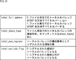
従って、tcovのシンタックスの第2のバリエーションでは、図30に示すようにISOBMFF(CoverageInformationBox)は記述され、ArbitraryRegionOnSphereStructは、上述の図19(第2の実施の形態)と同一とされる。また、パラメータは図31に示すように定義される。なお、上述した第2の実施の形態の変形例も含むことができる。 Therefore, in the second variation of the syntax of tcov, as shown in FIG. 30, ISOBMFF (CoverageInformationBox) is described, and ArbitraryRegionOnSphereStruct is the same as that in FIG. 19 (second embodiment) described above. The parameters are defined as shown in FIG. Note that a modification of the above-described second embodiment can be included.
また、tcovのシンタックスの第3のバリエーションでは、tcovでシグナルされる情報は、total coverage情報に加え、全てのfraction track(main含む)のcoverage情報を持ち、領域シグナル方法は、上述した第1の実施の形態と同一の方法とされる。 In a third variation of the syntax of tcov, the information signaled by tcov has coverage information of all fraction tracks (including main) in addition to the total coverage information, and the area signal method is the same as the first signal described above. This is the same method as in the embodiment.
従って、tcovのシンタックスの第3のバリエーションでは、図32に示すようにISOBMFF(CoverageInformationBox)は記述され、ArbitraryRegionOnSphereStructは、上述の図11(第1の実施の形態)と同一とされる。また、パラメータは図33に示すように定義される。なお、上述した第1の実施の形態の変形例も含むことができる。 Therefore, in the third variation of the syntax of tcov, ISOBMFF (CoverageInformationBox) is described as shown in FIG. 32, and ArbitraryRegionOnSphereStruct is the same as that in FIG. 11 (first embodiment) described above. The parameters are defined as shown in FIG. Note that a modification of the above-described first embodiment can be included.
なお、tcovのシンタックスの第3のバリエーションの変形例として、num_track_partitionは、TotalCoverageInformationBoxを持つ自trackを除いた数を設定し、tp_idで自trackのtrack_idをシグナルしなくてもよい。 As a modified example of the third variation of the syntax of tcov, num_track_partition is set to a number excluding the own track having TotalCoverageInformationBox, and tp_id does not need to signal the track_id of the own track.
また、tcovのシンタックスの第4のバリエーションでは、tcovでシグナルされる情報は、total coverage情報に加え、全てのfraction track(main含む)のcoverage情報を持ち、領域シグナル方法は、上述した第2の実施の形態と同一の方法とされる。 Further, in the fourth variation of the syntax of tcov, the information signaled by tcov has coverage information of all fraction tracks (including main) in addition to the total coverage information, and the area signal method is the same as the second signal described above. This is the same method as in the embodiment.
従って、tcovのシンタックスの第4のバリエーションでは、図34に示すようにISOBMFF(CoverageInformationBox)は記述され、ArbitraryRegionOnSphereStructは、上述の図19(第2の実施の形態)と同一とされる。また、パラメータは図35に示すように定義される。なお、上述した第2の実施の形態の変形例も含むことができる。 Therefore, in the fourth variation of the syntax of tcov, ISOBMFF (CoverageInformationBox) is described as shown in FIG. 34, and ArbitraryRegionOnSphereStruct is the same as that in FIG. 19 (second embodiment) described above. The parameters are defined as shown in FIG. Note that a modification of the above-described second embodiment can be included.
なお、tcovのシンタックスの第4のバリエーションの変形例として、num_track_partitionは、TotalCoverageInformationBoxを持つ自trackを除いた数を設定し、tp_idで自trackのtrack_idをシグナルしなくてもよい。 Note that, as a modified example of the fourth variation of the syntax of tcov, num_track_partition is set to a number excluding the own track having TotalCoverageInformationBox, and it is not necessary to signal the track_id of the own track by tp_id.
図36を参照して、第3の実施の形態において、main fraction trackにのみtcovを持つケース1について説明する。
With reference to FIG. 36, a
例えば、ケース1では、tcovを持つのがmain fraction trackとし、tcovを持たないのがfraction trackとする。そして、main fraction trackはTrack Reference(‘ofrc’)でfraction trackを参照することができ、fraction trackはTrack Reference(‘omfr’)でmain fraction trackを参照することができる。また、main fraction trackにのみTotalCoverageInformationBoxを持つ。
For example, in
ここで、例えば、tcovがtotal coverage情報のみ持つケース1−1の場合、カバレッジに関して重複する情報がない、シンプルな表現が可能となる。但し、total coverageを取得するために、main fraction trackを参照する必要があり、他のfraction trackのcoverageは、各fraction trackを参照しないと取得できない。 Here, for example, in case 1-1 where tcov has only total coverage information, a simple expression with no overlapping information on coverage is possible. However, in order to acquire total coverage, it is necessary to refer to the main fraction track, and the coverage of other fraction tracks cannot be acquired without referring to each fraction track.
また、例えば、tcovがtotal coverage情報に加え、全てのfraction track(main含む)のcoverage情報を持つケース1−2の場合、fraction trackのcoverageをmain fraction track内で取得できる。但し、total coverageを取得するために、main fraction trackを参照する必要がある。なお、ケース1の変形例として、prfrをmain fraction trackのみに持つようにしてもよい。また、ケース1−2の場合、tref (‘ofrc’)はなくてもよい。
In addition, for example, in case 1-2 where tcov has coverage information of all the fraction tracks (including main) in addition to the total coverage information, the coverage of the fraction track can be acquired in the main fraction track. However, in order to obtain total coverage, it is necessary to refer to the main fraction track. As a modification of
図37を参照して、第3の実施の形態において、すべてのfraction trackにtcovを持つケース2について説明する。
With reference to FIG. 37, a
例えば、ケース2では、main fraction track, fraction trackの区別はない。また、各fraction trackが相互にtrack reference‘omfr’で参照することができる。
For example, in
ここで、例えば、tcovがtotal coverage情報のみ持つケース2−1の場合、いずれのfraction trackもtotal coverageを有するため、total coverage情報を取得するのが容易である。但し、重複情報を持つためファイルサイズはケース1−1と比較して大きくなり、他のfraction trackのcoverageは、各fraction trackを参照しないと取得できない。 Here, for example, in case 2-1 in which tcov has only total coverage information, all fraction tracks have total coverage, so that it is easy to acquire total coverage information. However, the file size is larger than in case 1-1 because of having duplicate information, and the coverage of other fraction tracks cannot be obtained without referring to each fraction track.
また、例えば、tcovがtotal coverage情報に加え、fraction track(main含む)のcoverage情報を持つケース2−2の場合、total coverage, 各fraction trackのcoverageを一つのfraction track内で取得できる。但し、重複情報を持つためファイルサイズは、ケース1−1、ケース1−2、およびケース2−1のいずれと比較しても大きくなる。なお、ケース2−2の場合、tref (‘omfr’)はなくてもよい。 Further, for example, in case 2-2 in which tcov has coverage information of a fraction track (including main) in addition to the total coverage information, total coverage and coverage of each fraction track can be acquired in one fraction track. However, the file size is larger than any of Case 1-1, Case 1-2, and Case 2-1 due to the presence of duplicate information. In case 2-2, tref ('omfr') may not be provided.
次に、第3の実施の形態による実際のシグナル例について説明する。 Next, an example of an actual signal according to the third embodiment will be described.
図38では、ケース2−2で、tcovのシンタックスの第4のバリエーションを用い、各面をregionとして一つずつtrackに格納する。例えば、Region[0]はtrack_id:1とし、Region[1]はtrack_id:2とし、以下同様に、Region[5]はtrack_id:6とする。また、tcovのシグナルは、図38の下側に示すように記述される。 In FIG. 38, in the case 2-2, the fourth variation of the syntax of tcov is used, and each surface is stored in the track one by one as a region. For example, Region [0] is set to track_id: 1, Region [1] is set to track_id: 2, and similarly, Region [5] is set to track_id: 6. The tcov signal is described as shown in the lower part of FIG.
なお、第3の実施の形態の変形例として、total_full_sphereの代わりに、flagsを用いてもよい。 As a modification of the third embodiment, flags may be used instead of total_full_sphere.
<DASH MPDにおける領域シグナル方法>
図39乃至図50を参照して、本技術の第4の実施の形態として、DASH MPDにおける領域シグナル方法について説明する。<Area signal method in DASH MPD>
A region signal method in DASH MPD will be described as a fourth embodiment of the present technology with reference to FIGS. 39 to 50.
例えば、DASH MPDにおいて、各Representationがカバーする領域をシグナルすることができる。 For example, in the DASH MPD, an area covered by each Representation can be signaled.
シグナル方法としては、EssentialPropertyまたはSupplementalPropertyを用いることができ、EssentialPropertyはAdaptationSetの下に格納され、SupplementalPropertyはRepresentationの下に格納される。 As the signaling method, EssentialProperty or SupplementalProperty can be used. EssentialProperty is stored under AdaptationSet, and SupplementalProperty is stored under Representation.
例えば、SupplementalPropertyは、このPropertyを理解できないPlayerは、このProperty値を無視して、そのAdaptationSet(もしくはRepresentation, Sub-Representation)を利用してもよい。また、EssentialPropertyは、このPropertyを理解できないPlayerは、このPropertyの書かれているAdaptationSet(もしくはRepresentation, Sub-Representation)を無視しなければならない。 For example, a SupplementalProperty that does not understand this Property may ignore this Property value and use its AdaptationSet (or Representation, Sub-Representation). Also, a Player who cannot understand this Property must ignore AdaptationSet (or Representation, Sub-Representation) in which this Property is written.
図39には、拡張されたDASH MPDの第1の例が示されており、ここでは、上述した第1の実施の形態のシンタックスが使用されている。 FIG. 39 shows a first example of the extended DASH MPD, in which the syntax of the above-described first embodiment is used.
このようなシンタックスにおいて、coverage:arbitrary, totalcoverage:arbitraryの場合、0〜2はmandatoryとなり、3以降はnum_pointsに応じる。また、coverageがシグナルされない場合、カバレッジは360degreeフルを示す。一方、coverageのspatial_set_idがシグナルされる場合で、トータルカバレッジが360degreeフルでなければ、同じspatial_set_idを持つtotal coverageが必須となる。また、CoverageとTotalCoverageを一つのEssentialPropertyまたはSupplementalPropertyにまとめてもよい。 In such a syntax, in the case of coverage: arbitrary and totalcoverage: arbitrary, 0 to 2 are mandatory, and 3 and following correspond to num_points. Also, when no coverage is signaled, the coverage indicates 360 degree full. On the other hand, when the spatial_set_id of the coverage is signaled and the total coverage is not 360 degrees full, the total coverage having the same spatial_set_id is required. Also, Coverage and TotalCoverage may be combined into one EssentialProperty or SupplementalProperty.
図40および図41には、図39に示すような拡張されたDASH MPDにおいて使用されるパラメータの定義が示されている。 FIGS. 40 and 41 show definitions of parameters used in the extended DASH MPD as shown in FIG.
なお、上述した第1の実施の形態のシンタックスを使用する際の変形例として、Coverage, TotalCoverageのshape_type=2の場合について、点の数だけ図42に示すEssentialProperty(coverage:arbitrary, totalcoverage:arbitrary)をシグナルする。このとき、点を結ぶ順番は、EssentialPropertyまたはSupplementalPropertyの記載の順番でもよいし、EssentialPropertyまたはSupplementalProperty内に順番を示すパラメータを持ってもよい。 As a modification when using the syntax of the first embodiment described above, in the case of shape_type = 2 of Coverage and TotalCoverage, the number of points equal to the number of points in the EssentialProperty (coverage: arbitrary, totalcoverage: arbitrary: ). At this time, the order of connecting the dots may be the order of description of EssentialProperty or SupplementalProperty, or may have a parameter indicating the order in EssentialProperty or SupplementalProperty.
また、図43には、図42に示すシンタックスで使用されるパラメータの定義が記載されている。 FIG. 43 describes the definition of the parameters used in the syntax shown in FIG.
図44には、拡張されたDASH MPDの第2の例が示されており、ここでは、上述した第2の実施の形態のシンタックスが使用されている。 FIG. 44 shows a second example of the extended DASH MPD. Here, the syntax of the above-described second embodiment is used.
このようなシンタックスにおいて、coverage:arbitrary, totalcoverage:arbitraryの場合、kは2以上であり、2からnum_points-1までとされ、lは、0からnum_regions-1までとされる。 In such a syntax, in the case of coverage: arbitrary, totalcoverage: arbitrary, k is 2 or more, from 2 to num_points-1, and l is from 0 to num_regions-1.
また、coverageがシグナルされない場合、カバレッジは360degreeフルを示す。一方、coverageのspatial_set_idがシグナルされる場合で、トータルカバレッジが360degreeフルでなければ、同じspatial_set_idを持つtotal coverageが必須となる。また、CoverageとTotalCoverageを一つのEssentialPropertyまたはSupplementalPropertyにまとめてもよい。 Also, when no coverage is signaled, the coverage indicates 360 degree full. On the other hand, when the spatial_set_id of the coverage is signaled and the total coverage is not 360 degrees full, the total coverage having the same spatial_set_id is required. Also, Coverage and TotalCoverage may be combined into one EssentialProperty or SupplementalProperty.
図45および図46には、図44に示すような拡張されたDASH MPDにおいて使用されるパラメータの定義が示されている。 FIGS. 45 and 46 show definitions of parameters used in the extended DASH MPD as shown in FIG.
なお、上述した第2の実施の形態のシンタックスを使用する際の変形例として、領域の数だけ、図47に示すEssentialPropertyまたはSupplementalPropertyをシグナルする。そして、シグナルされた領域の合計がCoverageまたはTotal Coverageとなる。 As a modification example when the syntax of the second embodiment is used, EssentialProperty or SupplementalProperty shown in FIG. 47 is signaled by the number of regions. Then, the sum of the signaled areas becomes Coverage or Total Coverage.
次に、第4の実施の形態による実際のシグナル例について説明する。 Next, an example of an actual signal according to the fourth embodiment will be described.
図48では、上述したように拡張されたDASH MPDにおいて、第2の実施の形態のシンタックスを使用する例が示されている。つまり、図48の上側に示すように、八面体の8つの面が一つずつregionに分割されている。また、図48の下側には、各regionのpointのシグナルが示されており、図49には、そのシグナルが記述されたMPDの記述例が示されている。 FIG. 48 illustrates an example in which the syntax of the second embodiment is used in the DASH MPD extended as described above. That is, as shown in the upper part of FIG. 48, the eight faces of the octahedron are divided into regions one by one. In addition, the lower part of FIG. 48 shows the signal of the point of each region, and FIG. 49 shows an example of description of the MPD in which the signal is described.
なお、第4の実施の形態の変形例として、shape_type=2の場合のcoverage, total coverageについても、shape_type=0, 1と同じsyntaxを用いて表現してもよい。また、パラメータは、図46に示したパラメータが用いられる。 As a modification of the fourth embodiment, coverage and total coverage when shape_type = 2 may be expressed using the same syntax as shape_type = 0 and 1. As the parameters, the parameters shown in FIG. 46 are used.
このとき、center_pitch, center_yaw, hor_range, ver_rangeでシグナルされる領域は、実際のコンテンツのカバレッジと一致しなくてよい。ただし、実際のコンテンツカバレッジに包含され、かつ最大の領域がシグナルされる。例えば、図50に示すように、略三角形の実際のコンテンツカバレッジに包含され、かつ最大の領域となる略矩形の領域がシグナルされる。 At this time, the areas signaled by center_pitch, center_yaw, hor_range, and ver_range do not need to match the actual content coverage. However, the largest area included in the actual content coverage is signaled. For example, as shown in FIG. 50, a substantially rectangular area that is included in the substantially triangular actual content coverage and that is the largest area is signaled.
<システムの構成例および処理例>
図51乃至図55を参照して、上述したように球面上の領域をシグナルして全天球画像を配信するシステムについて説明する。<System configuration example and processing example>
With reference to FIGS. 51 to 55, a description will be given of a system that distributes an omnidirectional image by signaling an area on a spherical surface as described above.
図51は、本技術を適用した配信システムの構成例を示すブロック図である。 FIG. 51 is a block diagram illustrating a configuration example of a distribution system to which the present technology is applied.
図51の配信システム11は、撮影装置12、生成装置13、配信サーバ14、再生装置15、およびヘッドマウントディスプレイ16により構成される。配信システム11は、撮影装置12により撮影された撮影画像から全天球画像を生成し、全天球画像を用いて視聴者の視野範囲の表示画像を表示する。
The
具体的には、配信システム11の撮影装置12は、6個のカメラ12A−1乃至12A−6およびマイクロフォン12Bにより構成される。なお、以下では、カメラ12A−1乃至12A−6を特に区別する必要がない場合、それらをまとめてカメラ12Aという。
Specifically, the photographing
各カメラ12Aは動画像を撮影し、マイクロフォン12Bは周囲の音声を取得する。配信システム11は、各カメラ12Aにより撮影された6方向の動画像である撮影画像とマイクロフォン12Bにより取得された音声を、動画コンテンツとして生成装置13に供給する。なお、撮影装置12が備えるカメラの数は、複数であれば、6個以外であってもよい。
Each
生成装置13は、正距円筒図法を用いた方法により、撮影装置12から供給される撮影画像から全天球画像を生成し、1以上のビットレートで符号化して、各ビットレートの正距円筒ストリームを生成する。また、生成装置13は、キューブマッピングにより、撮影画像から全天球画像を生成し、1以上のビットレートで符号化して、各ビットレートのキューブストリームを生成する。また、生成装置13は、撮影装置12から供給される音声を符号化し、オーディオストリームを生成する。
The
生成装置13は、各ビットレートの正距円筒ストリーム、各ビットレートのキューブストリーム、およびオーディオストリームを、ISOBMFFファイル化する。生成装置13は、その結果生成されたISOBMFFファイルを配信サーバ14にアップロードする。
The generating
なお、ここでは、正距円筒ストリームとキューブストリームのビットレートが1以上であるようにするが、ビットレート以外の条件(例えば、画像のサイズ等)が1以上であるようにしてもよい。 Here, the bit rates of the equirectangular stream and the cube stream are set to 1 or more, but conditions other than the bit rate (for example, image size) may be set to 1 or more.
また、生成装置13は、動画コンテンツのセグメントファイルを管理するMPDファイルを生成し、配信サーバ14にアップロードする。セグメントとは、ビデオストリーム、オーディオストリームを数秒から10秒程度の時間単位でファイル化したものである。例えば、RegionMappingBoxを含むISOBMFFがセグメントファイルとして配信される。
Further, the
例えばMEPG-DASH (ISO/IEC 23009-1)を用いた配信を行う配信サーバ14は、生成装置13からアップロードされたセグメントファイルとMPDファイルを格納する。配信サーバ14は、クライアントとしての再生装置15からの要求に応じて、格納しているセグメントファイルを再生装置15に送信する。
For example, the
再生装置15は、配信サーバ14にISOBMFF ファイルを要求し、その要求に応じて送信されてくるISOBMFFファイルを受け取る。また、再生装置15は、ISOBMFFファイルに基づいて、再生装置15で行うことが可能なマッピングに対応する全天球画像の生成方法で生成された全天球画像のセグメントファイルを要求し、その要求に応じて送信されてくるセグメントファイルを受け取る。再生装置15は、受け取ったセグメントファイルに含まれるキューブストリーム(または正距円筒ストリームであってもよい)を復号する。再生装置15は、復号の結果得られる全天球画像を3Dモデルにマッピングすることにより、3Dモデル画像を生成する。
The
また、再生装置15は、カメラ15Aを内蔵し、ヘッドマウントディスプレイ16に付されたマーカ16Aを撮影する。そして、再生装置15は、マーカ16Aの撮影画像に基づいて、3Dモデルの座標系における視聴位置を検出する。さらに、再生装置15は、ヘッドマウントディスプレイ16のジャイロセンサ16Bの検出結果を、ヘッドマウントディスプレイ16から受け取る。再生装置15は、ジャイロセンサ16Bの検出結果に基づいて、3Dモデルの座標系における視聴者の視線方向を決定する。再生装置15は、視聴位置と視線方向に基づいて、3Dモデルの内部に位置する視聴者の視野範囲を決定する。
In addition, the
再生装置15は、視聴位置を焦点として、3Dモデル画像を視聴者の視野範囲に透視投影することにより、視聴者の視野範囲の画像を表示画像として生成する。再生装置15は、表示画像をヘッドマウントディスプレイ16に供給する。
The
ヘッドマウントディスプレイ16は、視聴者の頭部に装着され、再生装置15から供給される表示画像を表示する。ヘッドマウントディスプレイ16には、カメラ15Aにより撮影されるマーカ16Aが付されている。従って、視聴者は、ヘッドマウントディスプレイ16を頭部に装着した状態で、移動することにより視聴位置を指定することができる。また、ヘッドマウントディスプレイ16には、ジャイロセンサ16Bが内蔵され、そのジャイロセンサ16Bによる角速度の検出結果は再生装置15に伝送される。従って、視聴者は、ヘッドマウントディスプレイ16を装着した頭部を回転させることにより、視線方向を指定することができる。
The head mounted
図52は、生成装置の構成例を示すブロック図である。 FIG. 52 is a block diagram illustrating a configuration example of a generation device.
図52の生成装置13は、スティッチング処理部21、マッピング処理部22、region-wise packing処理部23、エンコーダ24、音声処理部25、エンコーダ26、ファイル生成部27、およびアップロード部28により構成される。
52 includes a
スティッチング処理部21は、フレームごとに、図51のカメラ12Aから供給される6方向の撮影画像の色や明るさを同一にし、重なりを除去して接続するスティッチング処理を行う。スティッチング処理部21は、スティッチング処理後のフレーム単位の撮影画像をマッピング処理部22に供給する。
The
マッピング処理部22は、この例ではキューブマッピングにより、スティッチング処理部21から供給される撮影画像から全天球画像を生成する。具体的には、マッピング処理部22は、スティッチング処理後の撮影画像をテクスチャとして立方体にマッピングし、その立方体の展開図の画像を全天球画像として生成する。マッピング処理部22は、全天球画像をregion-wise packing処理部23に供給する。なお、スティッチング処理部21とマッピング処理部22は、一体化されていてもよい。
In this example, the
region-wise packing処理部23はregion-wise packing処理を行う。すなわち、projected frameを領域ごとに位置とサイズを変更して2次元面上に配置してパッキング(packing)し、packed frameを生成する。region-wise packing処理部23はまた、margin_flag, region_margin_typeを含むRegionMappingBoxを生成する。
The region-wise
エンコーダ24は、region-wise packing処理部23から供給される全天球画像を1以上のビットレートで符号化し、キューブストリームを生成する。エンコーダ24は、各ビットレートのキューブストリームをファイル生成部27に供給する。
The
音声処理部25は、図51のマイクロフォン12Bから供給される音声を取得し、エンコーダ26に供給する。エンコーダ26は、音声処理部25から供給される音声を符号化し、オーディオストリームを生成する。エンコーダ26は、オーディオストリームをファイル生成部27に供給する。
The
ファイル生成部27は、各ビットレートのキューブストリーム、およびオーディオストリームを、セグメント単位でファイル化する。ファイル生成部27は、その結果生成されたセグメントファイルをアップロード部28に供給する。ファイル生成部27はまた、ISOBMFFファイルを生成し、アップロード部28に供給する。
The
このとき、ファイル生成部27は、上述したように拡張されたISOBMFFを生成することができ、そのISOBMFFには、領域情報がシグナルされている。即ち、ファイル生成部27は、球面上の複数の頂点をシグナルし、それらの頂点どうしを球面上の最短距離で結ぶことで球面上の領域を表現する領域情報(第1の実施の形態)を生成してISOBMFFに記述する。また、ファイル生成部27は、球面上の面ごとに各面の頂点をシグナルし、それらの頂点どうしを球面上の最短距離で結ぶことで形成される面領域を、面の数に応じてシグナルすることで球面上の領域を表現する領域情報(第2の実施の形態)を生成してISOBMFFに記述する。または、ファイル生成部27は、MPDを生成する際に、同様に、拡張されたMPDに領域情報がシグナル(第4の実施の形態)されるようにしてもよい。
At this time, the
アップロード部28は、ファイル生成部27から供給されるセグメントファイルとISOBMFFファイルとを、図51の配信サーバ14にアップロードする。
The upload
次に、画像を処理する場合を例として、再生装置15の構成例について説明する。
Next, an example of the configuration of the
図53は、再生装置の構成例を示すブロック図である。 FIG. 53 is a block diagram illustrating a configuration example of a playback device.
図53の再生装置15は、ファイル取得部31、ストリーム抽出部32、デコーダ33、projected frame生成部34,マッピング処理部35、描画部36、受け取り部37、視線検出部38、およびカメラ15Aを有している。
53 includes a
ファイル取得部31は、図51の配信サーバ14から再生対象のファイルを取得する。ストリーム抽出部32は、ファイル取得部31により取得されたファイルから、ビデオストリームを抽出する。デコーダ33は、ストリーム抽出部32により抽出されたビデオストリームをデコードする。projected frame生成部34は、デコーダ33によりデコードされた画像データからprojected frameを生成する。
The
マッピング処理部35は、projected frame生成部34から供給される全天球画像を立方体の6面のそれぞれにテクスチャとしてマッピングする。
The
描画部36は、マッピング処理部35から供給される3Dモデル画像を、視線検出部38から供給される視聴位置を焦点として、視聴者の視野範囲に透視投影することにより、視聴者の視野範囲の画像を表示画像として生成する。描画部36は、表示画像をヘッドマウントディスプレイ16に供給する。
The
受け取り部37は、図51のジャイロセンサ16Bの検出結果を、ヘッドマウントディスプレイ16から受け取り、視線検出部38に供給する。
The receiving
視線検出部38は、受け取り部37から供給されるジャイロセンサ16Bの検出結果に基づいて、3Dモデルの座標系における視聴者の視線方向を決定する。また、視線検出部38は、カメラ15Aからマーカ16Aの撮影画像を取得し、その撮影画像に基づいて、3Dモデルの座標系における視聴位置を検出する。視線検出部38は、3Dモデルの座標系における視聴位置と視線方向に基づいて、3Dモデルの座標系における視聴者の視野範囲を決定する。視線検出部38は、視聴者の視野範囲と視聴位置を描画部36に供給する。
The
図54のフローチャートを参照して、図52のファイル生成部27が実行するファイル生成処理について説明する。
The file generation process executed by the
ステップS11において、ファイル生成部27は、全天球ビデオは複数に分割されているか否かを判定する。
In step S11, the
ステップS11において、全天球ビデオは複数に分割されていると判定された場合、処理はステップS12に進み、ファイル生成部27は、全ての全天球ビデオの領域情報をもとに、tcovおよびEssentialProperty (totalcoverage) 情報を決定する。
If it is determined in step S11 that the spherical video is divided into a plurality of spherical videos, the process proceeds to step S12, where the
ステップS13において、ファイル生成部27は、個々の全天球ビデオの領域情報をもとに、それぞれのcoviおよびEssentialProperty(coverage)を決定する。
In step S13, the
一方、ステップS11において、全天球ビデオは複数に分割されていないと判定された場合、処理はステップS14に進み、ファイル生成部27は、全天球ビデオの領域情報をもとに、coviとEssentialProperty(coverage)情報を決定する。
On the other hand, if it is determined in step S11 that the omnidirectional video is not divided into a plurality of omnidirectional videos, the process proceeds to step S14, where the
ステップS13またはS14の処理後、処理はステップS15に進み、ファイル生成部27は、MPDとISOBMFFを生成した後、処理は終了される。
After the process in step S13 or S14, the process proceeds to step S15, in which the
図55のフローチャートを参照して、図53のファイル取得部31が実行するファイル取得処理について説明する。
The file acquisition process executed by the
ステップS21において、ファイル取得部31は、MPDのAdaptationSetのEssentialProperty(totalcoverage)を参照し、所望のtotal coverageとなるspatial_set_idを取得する。
In step S21, the
ステップS22において、ファイル取得部31は、MPDのAdaptationSetのEssentialProperty(coverage)を参照し、ステップS21で取得したspatial_set_idを持ち、かつ視聴方向に適合するAdaptationSetを選択する。
In step S22, the
ステップS23において、ファイル取得部31は、選択したAdaptationSetの中で、帯域幅に応じてRepresentationを選択して、参照されているファイルを取得して、処理は終了される。
In step S23, the
以上のように、ファイル生成部27は、MPDおよびISOBMFFを生成することができ、ファイル取得部31は、生成対象のファイルを取得することができる。
As described above, the
なお、上述のフローチャートを参照して説明した各処理は、必ずしもフローチャートとして記載された順序に沿って時系列に処理する必要はなく、並列的あるいは個別に実行される処理(例えば、並列処理あるいはオブジェクトによる処理)も含むものである。また、プログラムは、1のCPUにより処理されるものであっても良いし、複数のCPUによって分散処理されるものであっても良い。 Note that the processes described with reference to the above-described flowcharts do not necessarily need to be processed in chronological order in the order described in the flowchart, and may be performed in parallel or individually (for example, parallel processing or object processing). ). Further, the program may be processed by one CPU, or may be processed in a distributed manner by a plurality of CPUs.
また、上述した一連の処理(情報処理方法)は、ハードウエアにより実行することもできるし、ソフトウエアにより実行することもできる。一連の処理をソフトウエアにより実行する場合には、そのソフトウエアを構成するプログラムが、専用のハードウエアに組み込まれているコンピュータ、または、各種のプログラムをインストールすることで、各種の機能を実行することが可能な、例えば汎用のパーソナルコンピュータなどに、プログラムが記録されたプログラム記録媒体からインストールされる。 Further, the above-described series of processing (information processing method) can be executed by hardware or can be executed by software. When a series of processing is executed by software, a program constituting the software executes various functions by installing a computer built in dedicated hardware or installing various programs. For example, the program is installed from a program recording medium on which the program is recorded in a general-purpose personal computer or the like.
図56は、上述した一連の処理をプログラムにより実行するコンピュータのハードウエアの構成例を示すブロック図である。 FIG. 56 is a block diagram illustrating a configuration example of hardware of a computer that executes the series of processes described above by a program.
コンピュータにおいて、CPU(Central Processing Unit)101,ROM(Read Only Memory)102,RAM(Random Access Memory)103は、バス104により相互に接続されている。
In the computer, a CPU (Central Processing Unit) 101, a ROM (Read Only Memory) 102, and a RAM (Random Access Memory) 103 are mutually connected by a
バス104には、さらに、入出力インタフェース105が接続されている。入出力インタフェース105には、キーボード、マウス、マイクロフォンなどよりなる入力部106、ディスプレイ、スピーカなどよりなる出力部107、ハードディスクや不揮発性のメモリなどよりなる記憶部108、ネットワークインタフェースなどよりなる通信部109、磁気ディスク、光ディスク、光磁気ディスク、或いは半導体メモリなどのリムーバブルメディア111を駆動するドライブ110が接続されている。
The
以上のように構成されるコンピュータでは、CPU101が、例えば、記憶部108に記憶されているプログラムを、入出力インタフェース105及びバス104を介して、RAM103にロードして実行することにより、上述した一連の処理が行われる。
In the computer configured as described above, the
コンピュータ(CPU101)が実行するプログラムは、例えば、磁気ディスク(フレキシブルディスクを含む)、光ディスク(CD-ROM(Compact Disc-Read Only Memory),DVD(Digital Versatile Disc)等)、光磁気ディスク、もしくは半導体メモリなどよりなるパッケージメディアであるリムーバブルメディア111に記録して、あるいは、ローカルエリアネットワーク、インターネット、デジタル衛星放送といった、有線または無線の伝送媒体を介して提供される。
Programs executed by the computer (CPU 101) include, for example, a magnetic disk (including a flexible disk), an optical disk (CD-ROM (Compact Disc-Read Only Memory), a DVD (Digital Versatile Disc), etc.), a magneto-optical disk, or a semiconductor. The program is recorded on a
そして、プログラムは、リムーバブルメディア111をドライブ110に装着することにより、入出力インタフェース105を介して、記憶部108にインストールすることができる。また、プログラムは、有線または無線の伝送媒体を介して、通信部109で受信し、記憶部108にインストールすることができる。その他、プログラムは、ROM102や記憶部108に、あらかじめインストールしておくことができる。
The program can be installed in the
<構成の組み合わせ例>
なお、本技術は以下のような構成も取ることができる。
(1)
球面上の複数の頂点をシグナルし、それらの頂点どうしを球面上の最短距離で結ぶことで球面上の領域を表現する領域情報を生成する生成部
を備える情報処理装置。
(2)
前記領域情報には、複数の前記頂点を結ぶ規則が導入される
上記(1)に記載の情報処理装置。
(3)
前記領域情報には、複数の頂点でカバーされる領域に含まれる代表点がシグナルされる
上記(1)または(2)に記載の情報処理装置。
(4)
前記領域情報は、拡張されたISOBMFFによりシグナルされる
上記(1)から(3)までのいずれかに記載の情報処理装置。
(5)
前記領域情報は、tcovによりシグナルされる
上記(1)から(3)までのいずれかに記載の情報処理装置。
(6)
前記領域情報は、拡張されたDASH MPDによりシグナルされる
上記(1)から(3)までのいずれかに記載の情報処理装置。
(7)
球面上の複数の頂点をシグナルし、それらの頂点どうしを球面上の最短距離で結ぶことで球面上の領域を表現する領域情報を生成する
ステップを含む情報処理方法。
(8)
球面上の複数の頂点をシグナルし、それらの頂点どうしを球面上の最短距離で結ぶことで球面上の領域を表現する領域情報を生成する
ステップを含む情報処理をコンピュータに実行させるプログラム。
(9)
球面上の面ごとに各面の頂点をシグナルし、それらの頂点どうしを球面上の最短距離で結ぶことで形成される面領域を、面の数に応じてシグナルすることで球面上の領域を表現する領域情報を生成する生成部
を備える情報処理装置。
(10)
前記領域情報には、複数の前記頂点を結ぶ規則が導入され、前記面の数に従ってループを回すことで前記面領域がシグナルされる
上記(9)に記載の情報処理装置。
(11)
前記領域情報には、シグナルされた領域をカバーするか、シグナルされた領域以外をカバーするかを示すフラグが含まれる
上記(9)または(10)に記載の情報処理装置。
(12)
前記領域情報は、拡張されたISOBMFFによりシグナルされる
上記(9)から(11)までのいずれかに記載の情報処理装置。
(13)
前記領域情報は、tcovによりシグナルされる
上記(9)から(11)までのいずれかに記載の情報処理装置。
(14)
前記領域情報は、拡張されたDASH MPDによりシグナルされる
上記(9)から(11)までのいずれかに記載の情報処理装置。
(15)
球面上の面ごとに各面の頂点をシグナルし、それらの頂点どうしを球面上の最短距離で結ぶことで形成される面領域を、面の数に応じてシグナルすることで球面上の領域を表現する領域情報を生成する
ステップを含む情報処理方法。
(16)
球面上の面ごとに各面の頂点をシグナルし、それらの頂点どうしを球面上の最短距離で結ぶことで形成される面領域を、面の数に応じてシグナルすることで球面上の領域を表現する領域情報を生成する
ステップを含む情報処理をコンピュータに実行させるプログラム。<Example of configuration combination>
Note that the present technology can also have the following configurations.
(1)
An information processing apparatus comprising: a generation unit that signals a plurality of vertices on a sphere and connects the vertices with each other at a shortest distance on the sphere to generate region information representing a region on the sphere.
(2)
The information processing apparatus according to (1), wherein a rule connecting a plurality of the vertices is introduced into the area information.
(3)
The information processing apparatus according to (1) or (2), wherein a signal representing a representative point included in an area covered by a plurality of vertices is signaled as the area information.
(4)
The information processing apparatus according to any one of (1) to (3), wherein the area information is signaled by an extended ISOBMFF.
(5)
The information processing device according to any one of (1) to (3), wherein the region information is signaled by tcov.
(6)
The information processing apparatus according to any one of (1) to (3), wherein the area information is signaled by an extended DASH MPD.
(7)
An information processing method comprising: generating a region information representing a region on a sphere by signaling a plurality of vertices on the sphere and connecting the vertexes with the shortest distance on the sphere.
(8)
A program for causing a computer to execute information processing including a step of generating a region information representing a region on a sphere by signaling a plurality of vertices on the sphere and connecting the vertexes with the shortest distance on the sphere.
(9)
Signals the vertices of each surface for each surface on the sphere, and connects the vertices at the shortest distance on the sphere to form a surface area. An information processing device including a generation unit that generates region information to be expressed.
(10)
The information processing apparatus according to (9), wherein a rule connecting a plurality of the vertices is introduced into the area information, and the plane area is signaled by turning a loop according to the number of the planes.
(11)
The information processing apparatus according to (9) or (10), wherein the area information includes a flag indicating whether to cover a signaled area or to cover an area other than the signaled area.
(12)
The information processing apparatus according to any one of (9) to (11), wherein the area information is signaled by an extended ISOBMFF.
(13)
The information processing device according to any one of (9) to (11), wherein the region information is signaled by tcov.
(14)
The information processing apparatus according to any one of (9) to (11), wherein the area information is signaled by an extended DASH MPD.
(15)
Signals the vertices of each surface for each surface on the sphere, and connects the vertices at the shortest distance on the sphere to form a surface area. An information processing method including a step of generating region information to be represented.
(16)
Signals the vertices of each surface for each surface on the sphere, and connects the vertices at the shortest distance on the sphere to form a surface area. A program for causing a computer to execute information processing including a step of generating region information to be expressed.
なお、本実施の形態は、上述した実施の形態に限定されるものではなく、本開示の要旨を逸脱しない範囲において種々の変更が可能である。 Note that the present embodiment is not limited to the above-described embodiment, and various changes can be made without departing from the gist of the present disclosure.
11 配信システム, 12 撮影装置, 12A カメラ, 12B マイクロフォン, 13 生成装置, 14 配信サーバ, 15 再生装置, 15A カメラ, 16 ヘッドマウントディスプレイ, 16A マーカ, 16B ジャイロセンサ, 21 スティッチング処理部, 22 マッピング処理部, 23 region-wise packing処理部, 24 エンコーダ, 25 音声処理部, 26 エンコーダ, 27 ファイル生成部, 28 アップロード部, 31 ファイル取得部, 32 ストリーム抽出部, 33 デコーダ, 34 projected frame生成部, 35 マッピング処理部, 36 描画部, 37 受け取り部, 38 視線検出部
【0002】
tive streaming over HTTP(DASH)
発明の概要
発明が解決しようとする課題
[0006]
ところで、従来、OMAF CD(Omnidirectional Media Application Format Committee Draft)では、CoverageInformationBoxとして球面上領域カバレッジをシグナルしている。しかしながら、従来のOMAF CDでは対応することができないプロジェクションフォーマットがあり、より多様なプロジェクションフォーマットへの対応が求められていた。
[0007]
本開示は、このような状況に鑑みてなされたものであり、より多様なプロジェクションフォーマットで全天球映像の領域情報をシグナリングすることができるようにするものである。
課題を解決するための手段
[0008]
本開示の第1の側面の情報処理装置は、コンテンツのカバレッジ情報に基づいて、多面体の前記カバレッジ情報に対応する面ごとに各面の中心方向と水平方向および垂直方向の角度幅をシグナルし、前記シグナルを用いて球面上に形成される面領域を、前記カバレッジ情報に対応する面の数に応じてシグナルすることで球面上の領域を表現する領域情報を生成する生成部を備える。
[0009]
本開示の第1の側面の情報処理方法またはプログラムは、コンテンツのカバレッジ情報に基づいて、多面体の前記カバレッジ情報に対応する面ごとに各面の中心方向と水平方向および垂直方向の角度幅をシグナルし、前記シグナルを用いて球面上に形成される面領域を、前記カバレッジ情報に対応する面の数に応じてシグナルすることで球面上の領域を表現する領域情報を生成するステップを含む。
[0010]
本開示の第1の側面においては、コンテンツのカバレッジ情報に基づいて、多面体のカバレッジ情報に対応する面ごとに各面の中心方向と水平方向および垂直方向の角度幅をシグナルし、そのシグナルを用いて球面上に形成される面領域を、カバレッジ情報に対応する面の数に応じてシグナルすることで球面上の領域を表現する領域情報が生成される。
[0011]
本開示の第2の側面の情報処理装置は、コンテンツのカバレッジ情報に基づいて、多面体の前記カバレッジ情報に対応する面ごとに各面の頂点をシグナルし、それらの頂点どうしを球面上の最短距離で結ぶことで形成される面領域を、前記カバレッジ情報に対応する面の数に応じてシグナルすることで球面上の領域を表現する領域情報を生成する生成部を備える。
[0012][0002]
live streaming over HTTP (DASH)
SUMMARY OF THE INVENTION Problems to be Solved by the Invention [0006]
By the way, conventionally, in the OMAF CD (Omnidirectional Media Application Format Committee Draft), the coverage on the sphere is signaled as a CoverageInformationBox. However, there are projection formats that cannot be supported by the conventional OMAF CD, and there has been a demand for support for a wider variety of projection formats.
[0007]
The present disclosure has been made in view of such a situation, and it is an object of the present disclosure to be able to signal region information of a spherical image in a wider variety of projection formats.
Means for Solving the Problems [0008]
The information processing apparatus according to the first aspect of the present disclosure, based on coverage information of a content, signals a center direction of each surface and an angular width in a horizontal direction and a vertical direction for each surface corresponding to the coverage information of the polyhedron, A generation unit that generates region information expressing a region on a spherical surface by signaling a surface region formed on the spherical surface using the signal according to the number of surfaces corresponding to the coverage information;
[0009]
The information processing method or program according to the first aspect of the present disclosure, based on coverage information of a content, signals a center direction of each surface and an angular width in a horizontal direction and a vertical direction for each surface corresponding to the coverage information of the polyhedron. And generating a region information expressing the region on the spherical surface by signaling a surface region formed on the spherical surface using the signal according to the number of surfaces corresponding to the coverage information.
[0010]
In the first aspect of the present disclosure, based on coverage information of a content, the center direction of each surface and the angular width in the horizontal and vertical directions are signaled for each surface corresponding to the coverage information of the polyhedron, and the signal is used. The area information expressing the area on the spherical surface is generated by signaling the surface area formed on the spherical surface according to the number of surfaces corresponding to the coverage information.
[0011]
The information processing apparatus according to the second aspect of the present disclosure, based on coverage information of content, signals vertices of each surface for each surface corresponding to the coverage information of the polyhedron, and sets the vertices to the shortest distance on a spherical surface. And generating a region information expressing a region on a spherical surface by signaling a surface region formed by connecting in accordance with the number of surfaces corresponding to the coverage information.
[0012]
【0003】
[0013]
本開示の第2の側面においては、コンテンツのカバレッジ情報に基づいて、多面体のカバレッジ情報に対応する面ごとに各面の頂点をシグナルし、それらの頂点どうしを球面上の最短距離で結ぶことで形成される面領域を、カバレッジ情報に対応する面の数に応じてシグナルすることで球面上の領域を表現する領域情報が生成される。
発明の効果
[0014]
本開示の第1および第2の側面によれば、より多様なプロジェクションフォーマットで全天球映像の領域情報をシグナリングすることができる。
図面の簡単な説明
[0015]
[図1]viewport dependent processingについて説明する図である。
[図2]viewport情報を取り扱う球座標系を示す図である。
[図3]MPEGで規定されている領域情報の一例を示す図である。
[図4]shape_typeによる二種類の球面上領域表現を示す図である。
[図5]コンテンツのカバレッジ情報であるcoviの格納場所を示す図である。
[図6]従来のシンタックスでは正確に表現できない例を説明する図である。
[図7]三角形面で構成されるプロジェクションフォーマットの例を示す図である。
[図8]第1の実施の形態による球面上領域のシグナルの第1の例を示す図である。
[図9]第1の実施の形態による球面上領域のシグナルの第2の例を示す図である。
[図10]立方体の2つの面をシグナルすることの応用例について説明する図である。
[図11]第1の実施の形態における拡張されたISOBMFFの一例を示す図である。
[図12]point_yaw/pitchによる表現だけでは、カバレッジが一意に決まらない例を説明する図である。
[図13]第1の実施の形態におけるパラメータの定義を示す図である。
[図14]立方体の3面をシグナルする例を示す図である。[0003]
[0013]
In the second aspect of the present disclosure, the vertices of each surface are signaled for each surface corresponding to the coverage information of the polyhedron based on the coverage information of the content, and the vertices are connected at the shortest distance on the spherical surface. Signaling the formed surface region according to the number of surfaces corresponding to the coverage information generates region information representing a region on a spherical surface.
Effect of the Invention [0014]
According to the first and second aspects of the present disclosure, it is possible to signal region information of a spherical image in more various projection formats.
BRIEF DESCRIPTION OF THE DRAWINGS [0015]
FIG. 1 is a view for explaining viewport dependent processing.
FIG. 2 is a diagram showing a spherical coordinate system for handling viewport information.
FIG. 3 is a diagram showing an example of area information defined by MPEG.
FIG. 4 is a diagram showing two types of representation on a spherical surface by shape_type.
FIG. 5 is a diagram showing a storage location of covi, which is coverage information of content.
FIG. 6 is a diagram illustrating an example that cannot be accurately expressed by conventional syntax.
FIG. 7 is a diagram showing an example of a projection format composed of triangular surfaces.
FIG. 8 is a diagram showing a first example of a signal in a region on a spherical surface according to the first embodiment.
FIG. 9 is a diagram showing a second example of the signal in the region on the spherical surface according to the first embodiment.
FIG. 10 is a diagram illustrating an application example of signaling two surfaces of a cube.
FIG. 11 is a diagram showing an example of an extended ISOBMFF in the first embodiment.
FIG. 12 is a diagram for explaining an example in which coverage is not uniquely determined only by expression using point_yaw / pitch.
FIG. 13 is a diagram showing definitions of parameters in the first embodiment.
FIG. 14 is a diagram showing an example in which three planes of a cube are signaled.
【0011】
gsを用いてもよい。また、ArbitraryRegionOnSphereStructの中身を、RegionOnSphereStructの中でシグナルし、それらをshape_typeで切り替えてもよい。
[0053]
<ISOBMFFにおけるトラックの領域シグナル方法>
図18乃至図27を参照して、本技術の第2の実施の形態として、ISOBMFFにおけるトラックの領域シグナル方法の第2の例について説明する。
[0054]
第2の実施の形態では、ISOBMFF trackに格納されるコンテンツのカバレッジについて、多面体ごとにその多面体の頂点をyawおよびpitchでシグナルし、頂点どうしを球面上の最短距離で結ぶことで形成される面領域を面の数だけ複数シグナルして表現する。
[0055]
例えば、図18には、2つの面ごとに、それらの面の頂点をシグナルし、頂点どうしを球面上の最短距離で結ぶことで形成される面領域となる2つの面をシグナルすることで領域表現を行う例が示されている。
[0056]
このとき、それぞれの頂点を結ぶ球面上の線分はgreat circleの一部となる。また、このようなシグナルにより、図7に示したようなOHPおよびISPだけでなく、その他の多面体に対応するプロジェクションフォーマットが可能となる。
[0057]
図19には、拡張されたISOBMFF(CoverageInformationBox)およびArbitraryRegionOnSphereStructの一例が示されている。
[0058]
図19に示すISOBMFFでは、shape_type=2が導入されている。例えば、shape_type=2では、各頂点は、i=0とi=1,i=1とi=2,・・・,i=n−1とi=n,i=nとi=0の規則で、それぞれが球面上の最短距離で結ばれるように定義される。そして、ISOBMFFに示すように、面の数でfor loopを回すことにより、複数の面からなる領域をシグナルすることができる。
[0059]
また、図19に示すISOBMFFでは、exclude_flagが導入されている。exclude_flagが1の場合、シグナルされた領域以外がcoverageとなる
[0060]
図20を参照して、exclude_flagについて説明する。図20では、立方体の5面分(グレーのハッチングが施されている面以外)のカバレッジシグナル[0011]
gs may be used. Alternatively, the contents of the ArbitraryRegionOnSphereStruct may be signaled in the RegionOnSphereStruct, and these may be switched by shape_type.
[0053]
<Track signal method in ISOBMFF>
A second example of the track area signal method in the ISOBMFF will be described as a second embodiment of the present technology with reference to FIGS. 18 to 27.
[0054]
In the second embodiment, for coverage of content stored in the ISOBMFF track, a surface formed by signaling the vertices of the polyhedron with yaw and pitch for each polyhedron and connecting the vertices at the shortest distance on the spherical surface. The region is represented by multiple signals for the number of faces.
[0055]
For example, in FIG. 18, for each two surfaces, the vertices of those surfaces are signaled, and the two vertices are connected by the shortest distance on the spherical surface. An example of performing the expression is shown.
[0056]
At this time, a line segment on the spherical surface connecting the respective vertices becomes a part of the great circle. Further, such a signal enables a projection format corresponding to not only OHP and ISP as shown in FIG. 7 but also other polyhedrons.
[0057]
FIG. 19 shows an example of an extended ISOBMFF (CoverageInformationBox) and ArbitraryRegionOnSphereStruct.
[0058]
In the ISOBMFF shown in FIG. 19, shape_type = 2 is introduced. For example, when shape_type = 2, each vertex is a rule of i = 0 and i = 1, i = 1 and i = 2,..., I = n−1 and i = n, i = n and i = 0 Where each is defined to be connected at the shortest distance on the spherical surface. Then, as shown in ISOBMFF, by turning for loop by the number of surfaces, a region including a plurality of surfaces can be signaled.
[0059]
In the ISOBMFF shown in FIG. 19, an explicit_flag is introduced. When the exclude_flag is 1, the area other than the signaled area is covered [0060]
Exclude_flag will be described with reference to FIG. In FIG. 20, the coverage signals for the five faces of the cube (other than the faces with gray hatching) are shown.
Claims (16)
を備える情報処理装置。An information processing apparatus comprising: a generation unit that signals a plurality of vertices on a sphere and connects the vertices with each other at a shortest distance on the sphere to generate region information representing a region on the sphere.
請求項1に記載の情報処理装置。The information processing device according to claim 1, wherein a rule connecting a plurality of vertices is introduced into the area information.
請求項1に記載の情報処理装置。The information processing apparatus according to claim 1, wherein a representative point included in an area covered by a plurality of vertices is signaled as the area information.
請求項1に記載の情報処理装置。The information processing apparatus according to claim 1, wherein the area information is signaled by an extended ISOBMFF.
請求項1に記載の情報処理装置。The information processing device according to claim 1, wherein the region information is signaled by tcov.
請求項1に記載の情報処理装置。The information processing apparatus according to claim 1, wherein the area information is signaled by an extended DASH MPD.
ステップを含む情報処理方法。An information processing method comprising: generating a region information representing a region on a sphere by signaling a plurality of vertices on the sphere and connecting the vertexes with the shortest distance on the sphere.
ステップを含む情報処理をコンピュータに実行させるプログラム。A program for causing a computer to execute information processing including a step of generating a region information representing a region on a sphere by signaling a plurality of vertices on the sphere and connecting the vertexes with the shortest distance on the sphere.
を備える情報処理装置。Signals the vertices of each surface for each surface on the sphere, and connects the vertices at the shortest distance on the sphere to form a surface area. An information processing device including a generation unit that generates region information to be expressed.
請求項9に記載の情報処理装置。The information processing apparatus according to claim 9, wherein a rule connecting a plurality of the vertices is introduced into the area information, and the plane area is signaled by turning a loop according to the number of the planes.
請求項9に記載の情報処理装置。The information processing apparatus according to claim 9, wherein the area information includes a flag indicating whether to cover a signaled area or to cover an area other than the signaled area.
請求項9に記載の情報処理装置。The information processing device according to claim 9, wherein the area information is signaled by an extended ISOBMFF.
請求項9に記載の情報処理装置。The information processing apparatus according to claim 9, wherein the area information is signaled by tcov.
請求項9に記載の情報処理装置。The information processing apparatus according to claim 9, wherein the area information is signaled by an extended DASH MPD.
ステップを含む情報処理方法。Signals the vertices of each surface for each surface on the sphere, and connects the vertices at the shortest distance on the sphere to form a surface area. An information processing method including a step of generating region information to be represented.
ステップを含む情報処理をコンピュータに実行させるプログラム。Signals the vertices of each surface for each surface on the sphere, and connects the vertices at the shortest distance on the sphere to form a surface area. A program for causing a computer to execute information processing including a step of generating region information to be expressed.
Applications Claiming Priority (3)
| Application Number | Priority Date | Filing Date | Title |
|---|---|---|---|
| JP2017060221 | 2017-03-24 | ||
| JP2017060221 | 2017-03-24 | ||
| PCT/JP2018/009913 WO2018173875A1 (en) | 2017-03-24 | 2018-03-14 | Information processing device, information processing method, and program |
Publications (2)
| Publication Number | Publication Date |
|---|---|
| JPWO2018173875A1 true JPWO2018173875A1 (en) | 2020-02-20 |
| JP7243620B2 JP7243620B2 (en) | 2023-03-22 |
Family
ID=63586527
Family Applications (1)
| Application Number | Title | Priority Date | Filing Date |
|---|---|---|---|
| JP2019507591A Active JP7243620B2 (en) | 2017-03-24 | 2018-03-14 | Information processing device and program |
Country Status (10)
| Country | Link |
|---|---|
| US (1) | US20190394445A1 (en) |
| EP (1) | EP3606085A1 (en) |
| JP (1) | JP7243620B2 (en) |
| KR (1) | KR20190129865A (en) |
| CN (1) | CN110476436A (en) |
| AU (1) | AU2018238632A1 (en) |
| BR (1) | BR112019019311A2 (en) |
| CA (1) | CA3056739A1 (en) |
| RU (1) | RU2019129256A (en) |
| WO (1) | WO2018173875A1 (en) |
Families Citing this family (3)
| Publication number | Priority date | Publication date | Assignee | Title |
|---|---|---|---|---|
| US20220038517A1 (en) * | 2018-10-02 | 2022-02-03 | Sony Corporation | Information processing apparatus, information processing method, and program |
| US12211168B2 (en) | 2020-03-25 | 2025-01-28 | Alcacruz Inc. | Generating a representation of a spherical image |
| US11888913B2 (en) | 2021-04-28 | 2024-01-30 | Lemon Inc. | External stream representation properties |
Citations (5)
| Publication number | Priority date | Publication date | Assignee | Title |
|---|---|---|---|---|
| JP2009133798A (en) * | 2007-12-03 | 2009-06-18 | Furuno Electric Co Ltd | Position detection method and position detection device |
| WO2015060165A1 (en) * | 2013-10-22 | 2015-04-30 | シャープ株式会社 | Display processing device, distribution device, and metadata |
| JP2016509418A (en) * | 2013-01-18 | 2016-03-24 | キヤノン株式会社 | Method, device, and computer program for encapsulating divided time division media data |
| JP2019525675A (en) * | 2016-08-25 | 2019-09-05 | エルジー エレクトロニクス インコーポレイティド | Method for transmitting omnidirectional video, method for receiving omnidirectional video, omnidirectional video transmission device, and omnidirectional video reception device |
| JP2020501389A (en) * | 2016-11-17 | 2020-01-16 | インテル コーポレイション | Suggested viewport instructions for panoramic video |
Family Cites Families (8)
| Publication number | Priority date | Publication date | Assignee | Title |
|---|---|---|---|---|
| JP2003141562A (en) * | 2001-10-29 | 2003-05-16 | Sony Corp | Image processing apparatus and image processing method for non-planar image, storage medium, and computer program |
| JP2004272590A (en) * | 2003-03-07 | 2004-09-30 | Sony Corp | Data encoding device, data encoding method, and computer program |
| JP4945578B2 (en) * | 2007-01-04 | 2012-06-06 | 肇 鳴川 | Information processing method |
| JP6344723B2 (en) * | 2015-07-14 | 2018-06-20 | パナソニックIpマネジメント株式会社 | Video display system, video display device, and video display method |
| EP3419295A4 (en) * | 2016-02-17 | 2019-08-28 | LG Electronics Inc. | 360-DEGREE VIDEO TRANSMISSION METHOD, 360-DEGREE VIDEO RECEIVING METHOD, 360-DEGREE VIDEO TRANSMITTING APPARATUS, AND 360-DEGREE VIDEO RECEIVING APPARATUS |
| KR102506480B1 (en) * | 2016-06-14 | 2023-03-07 | 삼성전자주식회사 | Image processing apparatus and method for image processing thereof |
| CN205793093U (en) * | 2016-07-12 | 2016-12-07 | 冯心斌 | A kind of Set Top Box of Band clamp |
| KR102498598B1 (en) * | 2016-10-18 | 2023-02-14 | 삼성전자주식회사 | Image processing apparatus and method for image processing thereof |
-
2018
- 2018-03-14 CA CA3056739A patent/CA3056739A1/en not_active Abandoned
- 2018-03-14 BR BR112019019311A patent/BR112019019311A2/en not_active IP Right Cessation
- 2018-03-14 KR KR1020197026763A patent/KR20190129865A/en not_active Withdrawn
- 2018-03-14 CN CN201880018913.2A patent/CN110476436A/en active Pending
- 2018-03-14 EP EP18772069.3A patent/EP3606085A1/en not_active Withdrawn
- 2018-03-14 JP JP2019507591A patent/JP7243620B2/en active Active
- 2018-03-14 AU AU2018238632A patent/AU2018238632A1/en not_active Abandoned
- 2018-03-14 WO PCT/JP2018/009913 patent/WO2018173875A1/en not_active Ceased
- 2018-03-14 RU RU2019129256A patent/RU2019129256A/en not_active Application Discontinuation
- 2018-03-14 US US16/486,271 patent/US20190394445A1/en not_active Abandoned
Patent Citations (5)
| Publication number | Priority date | Publication date | Assignee | Title |
|---|---|---|---|---|
| JP2009133798A (en) * | 2007-12-03 | 2009-06-18 | Furuno Electric Co Ltd | Position detection method and position detection device |
| JP2016509418A (en) * | 2013-01-18 | 2016-03-24 | キヤノン株式会社 | Method, device, and computer program for encapsulating divided time division media data |
| WO2015060165A1 (en) * | 2013-10-22 | 2015-04-30 | シャープ株式会社 | Display processing device, distribution device, and metadata |
| JP2019525675A (en) * | 2016-08-25 | 2019-09-05 | エルジー エレクトロニクス インコーポレイティド | Method for transmitting omnidirectional video, method for receiving omnidirectional video, omnidirectional video transmission device, and omnidirectional video reception device |
| JP2020501389A (en) * | 2016-11-17 | 2020-01-16 | インテル コーポレイション | Suggested viewport instructions for panoramic video |
Non-Patent Citations (6)
| Title |
|---|
| 「DB2 FOR LINUX, UNIX, AND WINDOWS SPATIAL EXTENDERおよびGEODETIC DATA MANAGEMENT FEATURE ユーザーズ, vol. SC88-5900-02, JPN6018014267, May 2012 (2012-05-01), JP, pages 141 - 146, ISSN: 0004982509 * |
| JILL BOYCE, ET AL.: ""HEVC Additional Supplemental Enhancement Information (Draft 1)"", DOCUMENT: JCTVC-Z1005, [ONLINE], vol. JCTVC-Z1005 (version 1), JPN6018014264, 4 February 2017 (2017-02-04), pages 1 - 19, ISSN: 0004982507 * |
| JILL BOYCE, ET AL.: ""Spherical viewport SEI for HEVC and AVC 360 video"", DOCUMENT: JCTVC-Z0034, [ONLINE], vol. JCTVC-Z0034 (version 3), JPN6023004857, 13 January 2017 (2017-01-13), pages 1 - 5, ISSN: 0004982511 * |
| JILL BOYCE: ""Omnidirectional recommended viewport SEI Message"", DOCUMENT: JCTVC-AA0036, [ONLINE], vol. JCTVC-AA0036 (version 1), JPN6023004856, 22 March 2017 (2017-03-22), pages 1 - 3, ISSN: 0004982510 * |
| SEJIN OH, ET AL.: ""SEI message for signaling of 360-degree video information"", DOCUMENT: JCTVC-Z0026, [ONLINE], vol. JCTVC-Z0026 (version 3), JPN6018014261, 18 January 2017 (2017-01-18), pages 1 - 6, ISSN: 0004982506 * |
| 株式会社構造システム編, 「こんなに簡単!DRA−CAD12 3次元編 −モデリング/レンダリングから日影図/天空図まで−」, vol. 初版, JPN6018014266, April 2014 (2014-04-01), JP, pages 39, ISSN: 0004982508 * |
Also Published As
| Publication number | Publication date |
|---|---|
| KR20190129865A (en) | 2019-11-20 |
| JP7243620B2 (en) | 2023-03-22 |
| BR112019019311A2 (en) | 2020-04-14 |
| CA3056739A1 (en) | 2018-09-27 |
| AU2018238632A1 (en) | 2019-10-10 |
| EP3606085A4 (en) | 2020-02-05 |
| US20190394445A1 (en) | 2019-12-26 |
| RU2019129256A (en) | 2021-03-17 |
| EP3606085A1 (en) | 2020-02-05 |
| CN110476436A (en) | 2019-11-19 |
| WO2018173875A1 (en) | 2018-09-27 |
| RU2019129256A3 (en) | 2021-03-17 |
Similar Documents
| Publication | Publication Date | Title |
|---|---|---|
| JP7218826B2 (en) | Reproduction device and image generation method | |
| US10757392B2 (en) | Method of transmitting 360-degree video, method of receiving 360-degree video, device for transmitting 360-degree video, and device for receiving 360-degree video | |
| KR102246002B1 (en) | Method, device, and computer program to improve streaming of virtual reality media content | |
| EP2490179B1 (en) | Method and apparatus for transmitting and receiving a panoramic video stream | |
| JP7151486B2 (en) | Generation device, generation method, reproduction device and reproduction method | |
| EP3782368A1 (en) | Processing video patches for three-dimensional content | |
| JP7014156B2 (en) | Information processing equipment and information processing method | |
| US20200329266A1 (en) | Information processing apparatus, method for processing information, and storage medium | |
| JP2019516297A (en) | View-aware 360-degree video streaming | |
| JP2019526178A (en) | Stream spatially tiled omnidirectional video | |
| CN107454468A (en) | Method, apparatus and stream for formatting immersive video | |
| US10547879B2 (en) | Method and apparatus for streaming video content | |
| US20190199921A1 (en) | Method for transmitting 360-degree video, method for receiving 360-degree video, 360-degree video transmitting device, and 360-degree video receiving device | |
| JP7243620B2 (en) | Information processing device and program | |
| JP2019054416A (en) | Image processing apparatus and file generation apparatus | |
| TW201803358A (en) | Method, apparatus and stream for formatting immersive video for conventional and immersive imaging elements | |
| WO2019034804A2 (en) | Three-dimensional video processing | |
| JP7239029B2 (en) | Image processing device and file generation device |
Legal Events
| Date | Code | Title | Description |
|---|---|---|---|
| A529 | Written submission of copy of amendment under article 34 pct |
Free format text: JAPANESE INTERMEDIATE CODE: A5211 Effective date: 20190805 |
|
| A621 | Written request for application examination |
Free format text: JAPANESE INTERMEDIATE CODE: A621 Effective date: 20210202 |
|
| A131 | Notification of reasons for refusal |
Free format text: JAPANESE INTERMEDIATE CODE: A131 Effective date: 20220412 |
|
| A521 | Request for written amendment filed |
Free format text: JAPANESE INTERMEDIATE CODE: A523 Effective date: 20220606 |
|
| A131 | Notification of reasons for refusal |
Free format text: JAPANESE INTERMEDIATE CODE: A131 Effective date: 20220830 |
|
| A521 | Request for written amendment filed |
Free format text: JAPANESE INTERMEDIATE CODE: A523 Effective date: 20221021 |
|
| TRDD | Decision of grant or rejection written | ||
| A01 | Written decision to grant a patent or to grant a registration (utility model) |
Free format text: JAPANESE INTERMEDIATE CODE: A01 Effective date: 20230207 |
|
| A61 | First payment of annual fees (during grant procedure) |
Free format text: JAPANESE INTERMEDIATE CODE: A61 Effective date: 20230220 |
|
| R151 | Written notification of patent or utility model registration |
Ref document number: 7243620 Country of ref document: JP Free format text: JAPANESE INTERMEDIATE CODE: R151 |