JPWO2013153607A1 - Positioning device - Google Patents
Positioning device Download PDFInfo
- Publication number
- JPWO2013153607A1 JPWO2013153607A1 JP2013501064A JP2013501064A JPWO2013153607A1 JP WO2013153607 A1 JPWO2013153607 A1 JP WO2013153607A1 JP 2013501064 A JP2013501064 A JP 2013501064A JP 2013501064 A JP2013501064 A JP 2013501064A JP WO2013153607 A1 JPWO2013153607 A1 JP WO2013153607A1
- Authority
- JP
- Japan
- Prior art keywords
- positioning
- threshold value
- abnormality detection
- unit
- output
- Prior art date
- Legal status (The legal status is an assumption and is not a legal conclusion. Google has not performed a legal analysis and makes no representation as to the accuracy of the status listed.)
- Pending
Links
Images


Classifications
-
- G—PHYSICS
- G05—CONTROLLING; REGULATING
- G05B—CONTROL OR REGULATING SYSTEMS IN GENERAL; FUNCTIONAL ELEMENTS OF SUCH SYSTEMS; MONITORING OR TESTING ARRANGEMENTS FOR SUCH SYSTEMS OR ELEMENTS
- G05B19/00—Program-control systems
- G05B19/02—Program-control systems electric
- G05B19/18—Numerical control [NC], i.e. automatically operating machines, in particular machine tools, e.g. in a manufacturing environment, so as to execute positioning, movement or co-ordinated operations by means of program data in numerical form
- G05B19/414—Structure of the control system, e.g. common controller or multiprocessor systems, interface to servo, programmable interface controller
Landscapes
- Engineering & Computer Science (AREA)
- Human Computer Interaction (AREA)
- Manufacturing & Machinery (AREA)
- Physics & Mathematics (AREA)
- General Physics & Mathematics (AREA)
- Automation & Control Theory (AREA)
- Safety Devices In Control Systems (AREA)
- Numerical Control (AREA)
- Control Of Position Or Direction (AREA)
Abstract
大容量のメモリを必要とせずに機械の異常を早期に検知するとともに、機械の劣化を警報として検出することができる位置決め装置を得ることができるように、位置決めユニット(100)は、メモリ(120)と、溜りパルス量に応じて次の制御周期の位置決め出力を算出する位置決め制御部(111)と、正常運転時に、溜りパルス量の最大値を測定して、得られた溜りパルス量最大値(121)をメモリ(120)に記録し、定常運転時に、溜りパルス量最大値(121)に基づいて、当該溜りパルス量最大値(121)よりも大きい警報用しきい値(123)および当該警報用しきい値(123)よりも大きい異常検出用しきい値(122)を算出し、溜りパルス量が警報用しきい値(123)を越え、かつ異常検出用しきい値(122)を越えないとき、警報通知を発行し、溜りパルス量が異常検出用しきい値(122)を越えたとき、位置決め出力の出力を停止する異常検出部(112)と、を備える。The positioning unit (100) includes a memory (120) so as to obtain a positioning device that can detect a machine abnormality at an early stage without requiring a large-capacity memory and can detect deterioration of the machine as an alarm. ), Positioning control unit (111) that calculates the positioning output of the next control cycle according to the amount of droop pulses, and the maximum value of droop pulses obtained by measuring the maximum value of droop pulses during normal operation (121) is recorded in the memory (120), and the alarm threshold value (123) larger than the maximum accumulated pulse amount value (121) and the associated threshold value (121) are determined based on the accumulated pulse amount maximum value (121) during steady operation. An abnormality detection threshold value (122) larger than the alarm threshold value (123) is calculated, the amount of accumulated pulses exceeds the alarm threshold value (123), and the abnormality detection threshold value (1 When not exceeding 2), to issue an alarm notification, when the cumulative pulse exceeds the abnormality detection threshold value (122), comprising the abnormality detection unit stops outputting the positioning output (112), the.
Description
本発明は、被制御機械の位置決めを実行する位置決め装置に関する。 The present invention relates to a positioning device that performs positioning of a controlled machine.
プログラマブルコントローラ(Programmable Logic Controller、PLC)は、被制御機械が備えるサーボモータから入力されたフィードバックパルスをフィードバックループ制御する位置決めユニット(位置決め装置)が装着されて構成されることがある。また、位置決めユニットには、サーボモータのフィードバックパルスから偏差カウンタの溜りパルス量を算出して、溜りパルス量と許容値との比較に基づいてサーボモータによる位置制御時の機械の異常を検知するものがある。 A programmable controller (PLC) may be configured with a positioning unit (positioning device) that performs feedback loop control of a feedback pulse input from a servo motor included in a controlled machine. In addition, the positioning unit calculates the droop pulse amount of the deviation counter from the feedback pulse of the servo motor, and detects machine abnormalities during position control by the servo motor based on the comparison between the droop pulse amount and the allowable value. There is.
ここで、溜りパルス量にかかる許容値は、サーボモータの最高速度の仕様に基づいて算出されるため、サーボモータの制御内容によっては溜りパルス量と許容値の差が大きくなり、異常の検出が遅れる場合があった。そのため、位置決め装置が異常を検出してから位置制御を停止しても、制御対象の機械がダメージを受けてしまうという問題があった。 Here, since the allowable value for the droop pulse amount is calculated based on the specifications of the maximum speed of the servo motor, the difference between the droop pulse amount and the permissible value increases depending on the servo motor control contents, and abnormality detection is possible. There was a case to be late. Therefore, even if the position control is stopped after the positioning device detects an abnormality, there is a problem that the controlled machine is damaged.
これに関し、正常時の動作にかかる物理量として記憶しておき、当該記憶しておいた物理量と定常作業中の物理量とを逐次比較することで異常検出を行う、位置決め制御装置の技術が提案されている(例えば、特許文献1、特許文献2、および特許文献3参照)。 In this regard, there has been proposed a technique for a positioning control device that memorizes a physical quantity related to normal operation and detects an abnormality by sequentially comparing the stored physical quantity and a physical quantity during regular work. (For example, see Patent Document 1, Patent Document 2, and Patent Document 3).
しかしながら、上記特許文献1の技術によれば、位置決め制御装置は、正常時の全動作の変化を物理量として記憶しておくため、物理量を記憶するための大容量のメモリが別途必要であった。また、特許文献2の技術によれば、位置決め制御装置は、比較のための物理量として、無駄時間、立ち上がり時間、オーバーシュート量など、演算に時間がかかる量を用いることとしているので、迅速な異常検出ができないという問題があった。また、特許文献3の技術によれば、位置決め制御装置は、移動量と応答時間との関係を比較のための物理量として記憶しておくため、特許文献1にかかる位置決め制御装置と同様に、物理量を記憶するための大容量のメモリが必要であった。 However, according to the technique disclosed in Patent Document 1, since the positioning control device stores changes in all normal operations as physical quantities, a large-capacity memory for storing the physical quantities is required separately. Further, according to the technique of Patent Document 2, the positioning control apparatus uses a time-consuming amount such as a dead time, a rise time, and an overshoot amount as a physical quantity for comparison. There was a problem that it could not be detected. According to the technique of Patent Document 3, since the positioning control device stores the relationship between the movement amount and the response time as a physical quantity for comparison, the physical quantity is similar to the positioning control device according to Patent Document 1. A large-capacity memory for storing the memory was necessary.
本発明は、上記に鑑みてなされたものであって、大容量のメモリを必要とせずに機械の異常を早期に検知するとともに、機械の劣化を警報として検出することができる位置決め装置を得ることを目的とする。 The present invention has been made in view of the above, and obtains a positioning device capable of detecting a machine abnormality at an early stage without requiring a large-capacity memory and detecting a machine deterioration as an alarm. With the goal.
上述した課題を解決し、目的を達成するために、本発明は、記憶部と、被制御機械に対する位置決め出力と前記被制御機械からのエンコーダ入力との偏差に応じて次の制御周期の位置決め出力を算出する位置決め制御部と、正常運転時に、前記位置決め制御部が制御周期毎に算出する前記偏差の最大値を測定して、得られた最大値を前記記憶部に記録し、定常運転時に、前記記憶部に記録されている偏差の最大値に基づいて、当該最大値よりも大きい第1しきい値および当該第1しきい値よりも大きい第2しきい値を算出し、前記位置決め制御部が制御周期毎に算出する前記偏差と前記第1しきい値および前記第2しきい値とを比較し、前記偏差が前記第1しきい値を越え、かつ前記第2しきい値を越えないとき、前記位置決め制御部による位置決め出力の出力を止めることなく警報通知を発行し、前記偏差が前記第2しきい値を越えたとき、前記位置決め制御部による位置決め出力の出力を停止する異常検出部と、を備えることを特徴とする。 In order to solve the above-described problems and achieve the object, the present invention provides a positioning output for the next control cycle according to a deviation between a storage unit, a positioning output for the controlled machine, and an encoder input from the controlled machine. In the normal operation, during the normal operation, the positioning control unit measures the maximum value of the deviation calculated for each control cycle, and records the maximum value obtained in the storage unit, during the steady operation, Based on the maximum deviation recorded in the storage unit, a first threshold value greater than the maximum value and a second threshold value greater than the first threshold value are calculated, and the positioning control unit Compares the deviation calculated for each control period with the first threshold value and the second threshold value, and the deviation exceeds the first threshold value and does not exceed the second threshold value. By the positioning control unit An abnormality detection unit that issues an alarm notification without stopping the output of the positioning output, and stops the output of the positioning output by the positioning control unit when the deviation exceeds the second threshold value. Features.
本発明にかかる位置決め装置は、記憶部は動作中の制御周期毎の溜りパルス量を全て記録しておく必要がなく、かつ、複雑な演算を必要せずに異常を検出でき、かつ、異常を検出して被制御機械の動作を停止する前に、警報通知を出力するので、大容量のメモリを必要とせずに機械の異常を早期に検知するとともに、機械の劣化を警報として検出することができる位置決め装置を得ることができる。 In the positioning device according to the present invention, the storage unit does not need to record all the accumulated pulse amounts for each control cycle during operation, can detect an abnormality without requiring a complicated calculation, and can detect the abnormality. Since an alarm notification is output before detecting and stopping the operation of the controlled machine, it is possible to detect machine abnormalities at an early stage without requiring a large-capacity memory and to detect machine deterioration as an alarm. A positioning device that can be obtained can be obtained.
以下に、本発明にかかる位置決め装置の実施の形態を図面に基づいて詳細に説明する。なお、この実施の形態によりこの発明が限定されるものではない。 Embodiments of a positioning device according to the present invention will be described below in detail with reference to the drawings. Note that the present invention is not limited to the embodiments.
実施の形態.
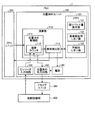
図1は、本発明の実施の形態の位置決めユニットを具備するPLCの構成を説明するブロック図である。図示するように、PLC1は、ドライブユニット300と被制御機械400とが接続されている。PLC1は、後述する演算部110の制御周期毎にドライブユニット300に対して被制御機械400の位置決めのための位置指令値(位置決め出力)を入力する。ドライブユニット300は、入力された位置決め出力に基づいて、被制御機械400の可動部を駆動する。被制御機械400は、可動部の現在位置を検出するエンコーダ(図示せず)を備えており、当該エンコーダによる位置検出値(エンコーダ入力)はPLC1に入力される。なお、ドライブユニット300は、例えばサーボアンプであってよい。また、被制御機械400が備える可動部は、サーボアンプにより駆動されるサーボモータであってよい。Embodiment.
FIG. 1 is a block diagram illustrating a configuration of a PLC including a positioning unit according to an embodiment of the present invention. As shown in the figure, the PLC 1 is connected to a
PLC1は、エンコーダ入力をフィードバック信号として用いて位置決め出力を算出する位置決めユニット100と、ユーザプログラムからの位置制御開始の要求に従って位置決めユニット100に対して位置決め制御を開始せしめるCPUユニット200とを備えている。なお、PLC1は、CPUユニット200、位置決めユニット100の他にも所望の機能ユニットが装着されて構成されることが可能である。PLC1に装着可能な機能ユニットには、例えば、CPUユニット200からの指令に基づき温度制御信号を出力する温度コントローラ装置などがある。 The PLC 1 includes a positioning unit 100 that calculates a positioning output using an encoder input as a feedback signal, and a CPU unit 200 that causes the positioning unit 100 to start positioning control in accordance with a request for starting position control from a user program. . The PLC 1 can be configured by mounting a desired functional unit in addition to the CPU unit 200 and the positioning unit 100. Examples of the functional unit that can be attached to the PLC 1 include a temperature controller device that outputs a temperature control signal based on a command from the CPU unit 200.
位置決めユニット100は、演算部110と、メモリ(記憶部)120と、エンコーダ入力回路130と、電源140と、位置決め出力回路150とを備えている。 The positioning unit 100 includes a calculation unit 110, a memory (storage unit) 120, an
電源140は、位置決め出力回路150を動作せしめるための電力を生成する。 The power source 140 generates electric power for operating the
エンコーダ入力回路130は、被制御機械400からのエンコーダ入力を受け付ける接続インタフェースであって、受け付けたエンコーダ入力を演算部110に転送する。 The
位置決め出力回路150は、演算部110(正確には後述の位置決め制御部111)が算出した位置決め出力をドライブユニット300に供給するための接続インタフェースである。位置決め出力回路150は、電源140から電力が供給されている間、位置決め出力をドライブユニット300に供給することができ、電源140からの電力供給が停止すると、位置決め出力の供給を停止する。 The
演算部110は、例えばCPU(Central Processing Unit)により構成される。演算部110は、所定のプログラムを実行することにより、位置決め制御部111および異常検出部112としての機能を実現する。 The calculation unit 110 is configured by, for example, a CPU (Central Processing Unit). The calculation unit 110 implements functions as the
位置決め制御部111は、CPUユニット200からの位置制御開始の要求を受け付けると、位置決め出力の算出を開始する。ここで、位置決め制御部111は、エンコーダ入力をフィードバック信号とするフィードバック制御の下で位置決め出力を算出することができる。具体的には、位置決め出力は、位置決め出力回路150に入力されるとともに、位置決め制御部111が備える偏差カウンタ113に入力される。偏差カウンタ113は、位置決め出力と、エンコーダ入力回路130が受け付けたエンコーダ入力との間の偏差(溜りパルス量)を算出する。位置決め制御部111は、当該溜りパルス量に応じて、次の制御周期で出力する位置決め出力を算出する。 When the
異常検出部112は、正常運転時の偏差カウンタ113の溜りパルス量の最大値を溜りパルス量最大値121としてメモリ120に記録しておき、溜りパルス量最大値121を用いて定常運転時の異常検出用しきい値122および警報用しきい値123を算出する。 The
警報用しきい値123は、溜りパルス量最大値121よりも大きい値が設定され、異常検出用しきい値122は、警報用しきい値123よりも大きい値が設定される。異常検出用しきい値122および警報用しきい値123の算出方法は、溜りパルス量最大値121を用いて算出されるのであればどのような方法であってもよい。例えば、異常検出部112は、溜りパルス量最大値121に予め定められた係数を乗じることによって異常検出用しきい値122および警報用しきい値123を求めるようにしてもよい。具体的には、異常検出部112は、溜りパルス量最大値121に1.1を乗じて得られる値を警報用しきい値123とし、溜りパルス量最大値121に1.2を乗じて得られる値を異常検出用しきい値122とするようにしてもよい。また、異常検出部112は、溜りパルス量最大値121に予め定められた値を加算することによって異常検出用しきい値122および警報用しきい値123を求めるようにしてもよい。 The
さらに、異常検出部112は、定常運転時には、偏差カウンタ113が制御周期毎に算出する溜りパルス量を、異常検出用しきい値122および警報用しきい値123の夫々と比較する。溜りパルス量が異常検出用しきい値122を越えたとき、異常検出部112は、電源140に停止信号を送信して電源140に位置決め出力回路150に対する電力供給を停止せしめる。これにより、被制御機械400の動作を即座に停止せしめることができる。また、例え位置決め出力回路150が故障していたとしても、被制御機械400を安全に停止せしめることができる。 Further, the
また、溜りパルス量が異常検出用しきい値122を越えずに警報用しきい値123を越えたとき、異常検出部112は、電源140に停止信号を発行することなく警報通知をCPUユニット200に発行する。CPUユニット200は、警報通知を受信すると、例えば、図示しないプログラマブル表示器などにユーザに対する警報を出力することができる。なお、位置決めユニット100がLEDランプなどユーザに対する警報を表示する出力手段を有している場合には、当該出力手段に警報を出力せしめるようにしてもよい。これにより、被制御機械400の運転を停止することなくユーザに異常を通知せしめることができるようになる。 When the accumulated pulse amount does not exceed the abnormality detection threshold value 122 but exceeds the
なお、異常検出部112の正常運転時の動作と定常運転時の動作と間の切り替えは、例えばユーザの操作により行われる。切り替えのための操作は、例えば上述のプログラマブル表示器を介して実行されるようにしてもよいし、位置決めユニット100にハードウェアスイッチを具備せしめ、ユーザが当該ハードウェアスイッチを操作することによって実行されるようにしてもよい。また、CPUユニット200にユーザプログラムを格納したり種々のパラメータを設定したりするために、プログラミングツールが接続される。当該プログラミングツールを用いて上記切り替え操作を実行できるようにしてもよい。即ち、ユーザが第1運転モードを指定した場合、異常検出部112は正常運転時の動作を実行し、ユーザが第2運転モードを指定した場合、異常検出部112は定常運転時の動作を実行する。 In addition, switching between the operation | movement at the time of normal operation of the
次に、図2および図3を参照して、本発明の実施の形態の位置決めユニット100の動作を説明する。図2は、正常動作時の位置決めユニット100の動作を説明するフローチャートである。 Next, with reference to FIG. 2 and FIG. 3, operation | movement of the positioning unit 100 of embodiment of this invention is demonstrated. FIG. 2 is a flowchart for explaining the operation of the positioning unit 100 during normal operation.
図2に示すように、CPU200からの位置制御開始が要求されると、位置決め制御部111は、位置制御を開始し(ステップS1)、偏差カウンタ113は、溜りパルス量を算出する(ステップS2)。なお、ステップS2〜ステップS4のループ処理は、制御周期毎に実行される。 As shown in FIG. 2, when the position control start from the CPU 200 is requested, the
ステップS2の処理の後、異常検出部112は、偏差カウンタ113が算出した溜りパルス量が位置制御開始から出力された溜りパルス量のうちの最大値であるか否かを判定する(ステップS3)。ステップS2の処理にて算出された溜りパルス量が位置制御開始から出力された溜りパルス量のうちの最大値ではない場合(ステップS3、No)、ステップS2の処理が再び実行される。ステップS2の処理にて算出された溜りパルス量が位置制御開始から出力された溜りパルス量のうちの最大値である場合(ステップS3、Yes)、異常検出部112は、メモリ120内に記録されている溜りパルス量最大値121をステップS2で算出された溜りパルス量で上書きする(ステップS4)。なお、ステップS2で算出された溜りパルス量が位置制御開始後に最初に算出された値である場合には、メモリ120には溜りパルス量最大値121が記録されていない状態であるので、当該最初に算出された値が溜りパルス量最大値121として記録される。その後、ステップS2の処理が実行される。 After the process of step S2, the
なお、ステップS2〜ステップS4のループ処理は、ユーザからの指令により停止せしめられるようにしてよい。当該ループ処理を停止するための指令は、プログラマブル表示器、プログラミングツール、その他の入力手段などにより、位置決めユニット100に入力されるようにしてよい。 Note that the loop processing from step S2 to step S4 may be stopped by a command from the user. A command for stopping the loop processing may be input to the positioning unit 100 by a programmable display, a programming tool, or other input means.
図3は、定常動作時の位置決めユニット100の動作を説明するフローチャートである。図3に示すように、CPU200からの位置制御開始が要求されると、まず、異常検出部112は、メモリ120に格納されている溜りパルス量最大値121に基づいて異常検出用しきい値122および警報用しきい値123を夫々算出する(ステップS11)。算出された異常検出用しきい値122および警報用しきい値123は、メモリ120に夫々記録される。 FIG. 3 is a flowchart for explaining the operation of the positioning unit 100 during the steady operation. As shown in FIG. 3, when the position control start is requested from the CPU 200, the
そして、位置決め制御部111は、位置制御を開始し(ステップS12)、偏差カウンタ113は、溜りパルス量を算出する(ステップS13)。なお、ステップS13、ステップS14、No、ステップS16、Noのループ処理は、制御周期毎に実行される。 Then, the
ステップS13の処理の後、異常検出部112は、ステップS13の処理にて算出された溜りパルス量が異常検出用しきい値122を越えたか否かを判定する(ステップS14)。溜りパルス量が異常検出用しきい値122を越えた場合(ステップS14、Yes)、異常検出部112は、電源140に停止信号を発行して(ステップS15)、動作を終了する。停止信号を受信した電源140は、位置決め出力回路150に供給している電力を停止するので、位置決め出力回路150による位置決め出力の出力が停止される。 After the process of step S13, the
溜りパルス量が異常検出用しきい値122を越えていない場合(ステップS14、No)、異常検出部112は、溜りパルス量が警報用しきい値123を越えたか否かを判定する(ステップS16)。溜りパルス量が警報用しきい値123を越えた場合(ステップS16、Yes)、異常検出部112は、CPUユニット200に警報通知を出力する(ステップS17)。その後、ステップS13の処理が実行される。溜りパルス量が警報用しきい値123を越えていない場合(ステップS16、No)、ステップS17の処理がスキップされる。 When the accumulated pulse amount does not exceed the abnormality detection threshold value 122 (No at Step S14), the
このように、本発明の実施の形態によれば、位置決めユニット100は、メモリ120と、被制御機械400に対する位置決め出力と被制御機械400からのエンコーダ入力との偏差(溜りパルス量)に応じて次の制御周期の位置決め出力を算出する位置決め制御部111と、正常運転時に、位置決め制御部111が制御周期毎に算出する溜りパルス量の最大値を測定して、得られた最大値(溜りパルス量最大値121)をメモリ120に記録し、定常運転時に、メモリ120に記録されている溜りパルス量最大値121に基づいて、当該溜りパルス量最大値121よりも大きい第1しきい値(警報用しきい値123)および当該警報用しきい値よりも大きい第2しきい値(異常検出用しきい値122)を算出し、位置決め制御部111が制御周期毎に算出する溜りパルス量と警報用しきい値123および異常検出用しきい値122とを比較し、溜りパルス量が警報用しきい値123を越え、かつ異常検出用しきい値122を越えないとき、位置決め制御部111による位置決め出力の出力を止めることなく警報通知を発行し、溜りパルス量が異常検出用しきい値122を越えたとき、位置決め制御部111による位置決め出力の出力を停止する異常検出部112と、を備えるように構成したので、メモリ120は動作中の制御周期毎の溜りパルス量を全て記録しておく必要がないので、メモリ120の容量を低減することができる。また、位置決めユニット100は、溜りパルス量と異常検出用しきい値122との間の単純比較に基づいて異常を検出するので、複雑な演算を必要としないので、異常を早期に検出することができる。また、位置決めユニット100は、異常を検出して被制御機械400の動作を停止する前に、警報通知を出力するので、ユーザは、被制御機械400が異常と判定されて停止するまえに当該被制御機械400の劣化を認識することができる。即ち、本発明の実施の形態によれば、大容量のメモリを必要とせずに機械の異常を早期に検知するとともに、機械の劣化を警報として検出することができる位置決め装置を得ることができる。 As described above, according to the embodiment of the present invention, the positioning unit 100 corresponds to the
また、位置決めユニット100は、被制御機械400に接続され、位置決め制御部111が算出した位置決め出力を制御周期毎に被制御機械400に出力する位置決め出力回路150と、位置決め出力回路150に当該位置決め出力回路150を駆動する電力を供給する電源140と、を備え、異常検出部112は、溜りパルス量が異常検出用しきい値122を越えたとき、電源140が位置決め出力回路150に供給する電力を停止せしめる、ように構成したので、位置決めユニット100は、異常検出部112が異常を検出したとき、位置決め出力回路150が故障していたとしても被制御機械400の動作を停止することができる。 The positioning unit 100 is connected to the controlled
なお、前述のように、異常検出部112は、メモリ120に記録されている溜りパルス量最大値121に所定第1の定数を乗じて警報用しきい値123を算出し、溜りパルス量最大値121に所定第2の定数を乗じて異常検出用しきい値122を算出する、ように構成してよい。同様に、異常検出部112は、メモリ120に記録されている溜りパルス量最大値121に所定第1の定数を加算して警報用しきい値123を算出し、溜りパルス量最大値121に所定第2の定数を加算して異常検出用しきい値122を算出する、ように構成してよい。これにより、被制御機械400の運転パターンが変更された場合であっても、ユーザは、試運転を行うことで異常検出用しきい値122および警報用しきい値123を自動的に設定することが可能となる。 As described above, the
なお、以上の説明においては、位置決め出力は位置指令値であり、エンコーダ入力は現在位置の位置検出値である、として説明したが、速度指令値を位置決め出力とし、速度検出値をエンコーダ入力とするようにしてもよい。 In the above description, the positioning output is the position command value, and the encoder input is the position detection value of the current position. However, the speed command value is the positioning output and the speed detection value is the encoder input. You may do it.
以上のように、本発明にかかる位置決め装置は、被制御機械の位置決めを実行する位置決め装置に適用して好適である。 As described above, the positioning device according to the present invention is suitable for application to a positioning device that performs positioning of a controlled machine.
100 位置決めユニット
110 演算部
111 位置決め制御部
112 異常検出部
113 偏差カウンタ
120 メモリ
121 溜りパルス量最大値
122 異常検出用しきい値
123 警報用しきい値
130 エンコーダ入力回路
140 電源
150 位置決め出力回路
200 CPUユニット
300 ドライブユニット
400 被制御機械DESCRIPTION OF SYMBOLS 100 Positioning unit 110
上述した課題を解決し、目的を達成するために、本発明は、記憶部と、被制御機械に対する位置決め出力と前記被制御機械からのエンコーダ入力との偏差に応じて次の制御周期の位置決め出力を算出する位置決め制御部と、正常運転時に、前記位置決め制御部が制御周期毎に算出する前記偏差の1つの最大値を複数の制御周期にわたって測定して、得られた最大値を前記記憶部に記録し、定常運転時に、前記記憶部に記録されている偏差の最大値に基づいて、当該最大値よりも大きい第1しきい値および当該第1しきい値よりも大きい第2しきい値を算出し、前記位置決め制御部が制御周期毎に算出する前記偏差と前記第1しきい値および前記第2しきい値とを比較し、前記偏差が前記第1しきい値を越え、かつ前記第2しきい値を越えないとき、前記位置決め制御部による位置決め出力の出力を止めることなく警報通知を発行し、前記偏差が前記第2しきい値を越えたとき、前記位置決め制御部による位置決め出力の出力を停止する異常検出部と、を備えることを特徴とする。 In order to solve the above-described problems and achieve the object, the present invention provides a positioning output for the next control cycle according to a deviation between a storage unit, a positioning output for the controlled machine, and an encoder input from the controlled machine. A positioning control unit that calculates the difference, and during normal operation, the maximum value of the deviation calculated by the positioning control unit for each control cycle is measured over a plurality of control cycles , and the obtained maximum value is stored in the storage unit. The first threshold value greater than the maximum value and the second threshold value greater than the first threshold value are recorded based on the maximum deviation value recorded in the storage unit during steady operation. Calculating, comparing the deviation calculated by the positioning control unit for each control cycle with the first threshold value and the second threshold value, the deviation exceeding the first threshold value, and the first threshold value. 2 Do not exceed the threshold An abnormality detection unit that issues an alarm notification without stopping positioning output from the positioning control unit and stops positioning output output by the positioning control unit when the deviation exceeds the second threshold value. And.
Claims (5)
被制御機械に対する位置決め出力と前記被制御機械からのエンコーダ入力との偏差に応じて次の制御周期の位置決め出力を算出する位置決め制御部と、
正常運転時に、前記位置決め制御部が制御周期毎に算出する前記偏差の最大値を測定して、得られた最大値を前記記憶部に記録し、定常運転時に、前記記憶部に記録されている偏差の最大値に基づいて、当該最大値よりも大きい第1しきい値および当該第1しきい値よりも大きい第2しきい値を算出し、前記位置決め制御部が制御周期毎に算出する前記偏差と前記第1しきい値および前記第2しきい値とを比較し、前記偏差が前記第1しきい値を越え、かつ前記第2しきい値を越えないとき、前記位置決め制御部による位置決め出力の出力を止めることなく警報通知を発行し、前記偏差が前記第2しきい値を越えたとき、前記位置決め制御部による位置決め出力の出力を停止する異常検出部と、
を備えることを特徴とする位置決め装置。A storage unit;
A positioning control unit that calculates a positioning output of the next control cycle in accordance with a deviation between a positioning output for the controlled machine and an encoder input from the controlled machine;
During normal operation, the positioning control unit measures the maximum value of the deviation calculated for each control cycle, records the maximum value obtained in the storage unit, and is recorded in the storage unit during steady operation. Based on the maximum value of the deviation, the first threshold value larger than the maximum value and the second threshold value larger than the first threshold value are calculated, and the positioning control unit calculates each control cycle. When the deviation is compared with the first threshold value and the second threshold value, and the deviation exceeds the first threshold value and does not exceed the second threshold value, positioning by the positioning control unit An abnormality detection unit that issues an alarm notification without stopping output and stops output of positioning output by the positioning control unit when the deviation exceeds the second threshold value;
A positioning device comprising:
前記位置決め出力回路に当該位置決め出力回路を駆動する電力を供給する電源と、
を備え、
前記異常検出部は、前記偏差が前記第2しきい値を越えたとき、前記電源が前記位置決め出力回路に供給する電力を停止せしめる、
ことを特徴とする請求項1に記載の位置決め装置。A positioning output circuit that is connected to the controlled machine and outputs a positioning output calculated by the positioning control unit to the control machine for each control cycle;
A power supply for supplying power for driving the positioning output circuit to the positioning output circuit;
With
The abnormality detection unit stops the power supplied from the power source to the positioning output circuit when the deviation exceeds the second threshold value.
The positioning device according to claim 1.
ことを特徴とする請求項1に記載の位置決め装置。The abnormality detection unit calculates the first threshold value by multiplying the maximum value recorded in the storage unit by a first constant, and multiplies the maximum value by a second constant to perform the second step. Calculate the threshold,
The positioning device according to claim 1.
ことを特徴とする請求項1に記載の位置決め装置。The abnormality detection unit calculates a first threshold value by adding a first constant to the maximum value recorded in the storage unit, adds a second constant to the maximum value, and adds the second constant. 2 Calculate the threshold value,
The positioning device according to claim 1.
ことを特徴とする請求項1乃至請求項4のうちの何れか一項に記載の位置決め装置。The normal operation is when the first operation mode is designated, and the steady operation is when the second operation mode is designated.
The positioning device according to any one of claims 1 to 4, wherein the positioning device is characterized in that:
Applications Claiming Priority (1)
| Application Number | Priority Date | Filing Date | Title |
|---|---|---|---|
| PCT/JP2012/059717 WO2013153607A1 (en) | 2012-04-09 | 2012-04-09 | Positioning device |
Publications (1)
| Publication Number | Publication Date |
|---|---|
| JPWO2013153607A1 true JPWO2013153607A1 (en) | 2015-12-17 |
Family
ID=49327217
Family Applications (1)
| Application Number | Title | Priority Date | Filing Date |
|---|---|---|---|
| JP2013501064A Pending JPWO2013153607A1 (en) | 2012-04-09 | 2012-04-09 | Positioning device |
Country Status (3)
| Country | Link |
|---|---|
| JP (1) | JPWO2013153607A1 (en) |
| TW (1) | TW201341997A (en) |
| WO (1) | WO2013153607A1 (en) |
Families Citing this family (3)
| Publication number | Priority date | Publication date | Assignee | Title |
|---|---|---|---|---|
| JP2019040435A (en) * | 2017-08-25 | 2019-03-14 | アズビル株式会社 | Controller and deteriorated position detection method |
| JP7098071B2 (en) * | 2019-11-19 | 2022-07-08 | 三菱電機株式会社 | Deterioration determination device, threshold determination device, threshold determination method, and threshold determination program |
| JP7320473B2 (en) * | 2020-03-27 | 2023-08-03 | Ckd株式会社 | butterfly valve |
Citations (5)
| Publication number | Priority date | Publication date | Assignee | Title |
|---|---|---|---|---|
| JPH05189027A (en) * | 1992-01-08 | 1993-07-30 | Hitachi Ltd | Signal abnormality diagnostic device and its use method |
| JP2002014721A (en) * | 2000-06-30 | 2002-01-18 | Mitsubishi Heavy Ind Ltd | Alarm issuing notification device |
| JP2005038910A (en) * | 2003-07-16 | 2005-02-10 | Juki Corp | Component mounter and self-diagnosis method thereof |
| WO2006114843A1 (en) * | 2005-04-08 | 2006-11-02 | Mitsubishi Denki Kabushiki Kaisha | Servo motor controller |
| JP2010124645A (en) * | 2008-11-21 | 2010-06-03 | Denso Wave Inc | Robot |
-
2012
- 2012-04-09 WO PCT/JP2012/059717 patent/WO2013153607A1/en not_active Ceased
- 2012-04-09 JP JP2013501064A patent/JPWO2013153607A1/en active Pending
- 2012-10-02 TW TW101136314A patent/TW201341997A/en unknown
Patent Citations (5)
| Publication number | Priority date | Publication date | Assignee | Title |
|---|---|---|---|---|
| JPH05189027A (en) * | 1992-01-08 | 1993-07-30 | Hitachi Ltd | Signal abnormality diagnostic device and its use method |
| JP2002014721A (en) * | 2000-06-30 | 2002-01-18 | Mitsubishi Heavy Ind Ltd | Alarm issuing notification device |
| JP2005038910A (en) * | 2003-07-16 | 2005-02-10 | Juki Corp | Component mounter and self-diagnosis method thereof |
| WO2006114843A1 (en) * | 2005-04-08 | 2006-11-02 | Mitsubishi Denki Kabushiki Kaisha | Servo motor controller |
| JP2010124645A (en) * | 2008-11-21 | 2010-06-03 | Denso Wave Inc | Robot |
Also Published As
| Publication number | Publication date |
|---|---|
| TW201341997A (en) | 2013-10-16 |
| WO2013153607A1 (en) | 2013-10-17 |
Similar Documents
| Publication | Publication Date | Title |
|---|---|---|
| JP5269262B1 (en) | Numerical controller | |
| US9746858B2 (en) | Control device for automatically starting warm-up | |
| US10029340B2 (en) | Machine tool | |
| JP6203701B2 (en) | Electric machine and program | |
| CN103688178B (en) | Numerical control device | |
| US20160016313A1 (en) | Robot control system having stop function | |
| JP2006155351A (en) | Controller | |
| KR20150074258A (en) | Method and Apparatus for Monitoring Cutting Load of Machine Tool | |
| JPWO2013153607A1 (en) | Positioning device | |
| US10088828B2 (en) | Controlling load ratio induced shut-down conditions in numerical control devices | |
| CN110695769B (en) | Abnormality detection device for machine tool | |
| JP5758971B2 (en) | Injection molding machine with continuous operation during power failure | |
| US9983570B2 (en) | Multiple system numerical control device | |
| CN105278450A (en) | Numerical controller performing repetitive machining | |
| JP2002036321A (en) | Method and apparatus for detecting condition of mold of injection molding machine | |
| JP5811035B2 (en) | Electric injection molding machine load status display method and electric injection molding machine drive device | |
| JP6087262B2 (en) | Numerical controller | |
| JP2014046497A (en) | Method for estimating deterioration of heater of injection molding machine, and injection molding machine | |
| JP5995688B2 (en) | Actuator control device | |
| JP2014240162A (en) | Valve gate control device of injection molding machine | |
| JPH1080055A (en) | Method for suppressing and controlling overheating of motor | |
| JP2005032279A (en) | Numerical controller | |
| JP2020065364A (en) | Abnormality detection device, abnormality detection method, and program | |
| WO2023153048A1 (en) | Power conversion device | |
| US7088069B2 (en) | Load monitoring method for motor-driven injection molding machine |
Legal Events
| Date | Code | Title | Description |
|---|---|---|---|
| A02 | Decision of refusal |
Free format text: JAPANESE INTERMEDIATE CODE: A02 Effective date: 20130521 |