JPWO2008132890A1 - Method and apparatus for image encoding and image decoding - Google Patents
Method and apparatus for image encoding and image decoding Download PDFInfo
- Publication number
- JPWO2008132890A1 JPWO2008132890A1 JP2009511709A JP2009511709A JPWO2008132890A1 JP WO2008132890 A1 JPWO2008132890 A1 JP WO2008132890A1 JP 2009511709 A JP2009511709 A JP 2009511709A JP 2009511709 A JP2009511709 A JP 2009511709A JP WO2008132890 A1 JPWO2008132890 A1 JP WO2008132890A1
- Authority
- JP
- Japan
- Prior art keywords
- quantization
- modulation
- matrix
- image signal
- index
- Prior art date
- Legal status (The legal status is an assumption and is not a legal conclusion. Google has not performed a legal analysis and makes no representation as to the accuracy of the status listed.)
- Abandoned
Links
Images


Classifications
-
- H—ELECTRICITY
- H04—ELECTRIC COMMUNICATION TECHNIQUE
- H04N—PICTORIAL COMMUNICATION, e.g. TELEVISION
- H04N19/00—Methods or arrangements for coding, decoding, compressing or decompressing digital video signals
- H04N19/10—Methods or arrangements for coding, decoding, compressing or decompressing digital video signals using adaptive coding
- H04N19/189—Methods or arrangements for coding, decoding, compressing or decompressing digital video signals using adaptive coding characterised by the adaptation method, adaptation tool or adaptation type used for the adaptive coding
- H04N19/192—Methods or arrangements for coding, decoding, compressing or decompressing digital video signals using adaptive coding characterised by the adaptation method, adaptation tool or adaptation type used for the adaptive coding the adaptation method, adaptation tool or adaptation type being iterative or recursive
-
- H—ELECTRICITY
- H04—ELECTRIC COMMUNICATION TECHNIQUE
- H04N—PICTORIAL COMMUNICATION, e.g. TELEVISION
- H04N19/00—Methods or arrangements for coding, decoding, compressing or decompressing digital video signals
- H04N19/50—Methods or arrangements for coding, decoding, compressing or decompressing digital video signals using predictive coding
- H04N19/503—Methods or arrangements for coding, decoding, compressing or decompressing digital video signals using predictive coding involving temporal prediction
- H04N19/51—Motion estimation or motion compensation
-
- H—ELECTRICITY
- H04—ELECTRIC COMMUNICATION TECHNIQUE
- H04N—PICTORIAL COMMUNICATION, e.g. TELEVISION
- H04N19/00—Methods or arrangements for coding, decoding, compressing or decompressing digital video signals
- H04N19/10—Methods or arrangements for coding, decoding, compressing or decompressing digital video signals using adaptive coding
- H04N19/102—Methods or arrangements for coding, decoding, compressing or decompressing digital video signals using adaptive coding characterised by the element, parameter or selection affected or controlled by the adaptive coding
- H04N19/124—Quantisation
- H04N19/126—Details of normalisation or weighting functions, e.g. normalisation matrices or variable uniform quantisers
-
- H—ELECTRICITY
- H04—ELECTRIC COMMUNICATION TECHNIQUE
- H04N—PICTORIAL COMMUNICATION, e.g. TELEVISION
- H04N19/00—Methods or arrangements for coding, decoding, compressing or decompressing digital video signals
- H04N19/10—Methods or arrangements for coding, decoding, compressing or decompressing digital video signals using adaptive coding
- H04N19/134—Methods or arrangements for coding, decoding, compressing or decompressing digital video signals using adaptive coding characterised by the element, parameter or criterion affecting or controlling the adaptive coding
- H04N19/146—Data rate or code amount at the encoder output
- H04N19/147—Data rate or code amount at the encoder output according to rate distortion criteria
-
- H—ELECTRICITY
- H04—ELECTRIC COMMUNICATION TECHNIQUE
- H04N—PICTORIAL COMMUNICATION, e.g. TELEVISION
- H04N19/00—Methods or arrangements for coding, decoding, compressing or decompressing digital video signals
- H04N19/10—Methods or arrangements for coding, decoding, compressing or decompressing digital video signals using adaptive coding
- H04N19/169—Methods or arrangements for coding, decoding, compressing or decompressing digital video signals using adaptive coding characterised by the coding unit, i.e. the structural portion or semantic portion of the video signal being the object or the subject of the adaptive coding
- H04N19/17—Methods or arrangements for coding, decoding, compressing or decompressing digital video signals using adaptive coding characterised by the coding unit, i.e. the structural portion or semantic portion of the video signal being the object or the subject of the adaptive coding the unit being an image region, e.g. an object
- H04N19/176—Methods or arrangements for coding, decoding, compressing or decompressing digital video signals using adaptive coding characterised by the coding unit, i.e. the structural portion or semantic portion of the video signal being the object or the subject of the adaptive coding the unit being an image region, e.g. an object the region being a block, e.g. a macroblock
-
- H—ELECTRICITY
- H04—ELECTRIC COMMUNICATION TECHNIQUE
- H04N—PICTORIAL COMMUNICATION, e.g. TELEVISION
- H04N19/00—Methods or arrangements for coding, decoding, compressing or decompressing digital video signals
- H04N19/10—Methods or arrangements for coding, decoding, compressing or decompressing digital video signals using adaptive coding
- H04N19/169—Methods or arrangements for coding, decoding, compressing or decompressing digital video signals using adaptive coding characterised by the coding unit, i.e. the structural portion or semantic portion of the video signal being the object or the subject of the adaptive coding
- H04N19/18—Methods or arrangements for coding, decoding, compressing or decompressing digital video signals using adaptive coding characterised by the coding unit, i.e. the structural portion or semantic portion of the video signal being the object or the subject of the adaptive coding the unit being a set of transform coefficients
-
- H—ELECTRICITY
- H04—ELECTRIC COMMUNICATION TECHNIQUE
- H04N—PICTORIAL COMMUNICATION, e.g. TELEVISION
- H04N19/00—Methods or arrangements for coding, decoding, compressing or decompressing digital video signals
- H04N19/10—Methods or arrangements for coding, decoding, compressing or decompressing digital video signals using adaptive coding
- H04N19/189—Methods or arrangements for coding, decoding, compressing or decompressing digital video signals using adaptive coding characterised by the adaptation method, adaptation tool or adaptation type used for the adaptive coding
- H04N19/19—Methods or arrangements for coding, decoding, compressing or decompressing digital video signals using adaptive coding characterised by the adaptation method, adaptation tool or adaptation type used for the adaptive coding using optimisation based on Lagrange multipliers
-
- H—ELECTRICITY
- H04—ELECTRIC COMMUNICATION TECHNIQUE
- H04N—PICTORIAL COMMUNICATION, e.g. TELEVISION
- H04N19/00—Methods or arrangements for coding, decoding, compressing or decompressing digital video signals
- H04N19/60—Methods or arrangements for coding, decoding, compressing or decompressing digital video signals using transform coding
- H04N19/61—Methods or arrangements for coding, decoding, compressing or decompressing digital video signals using transform coding in combination with predictive coding
-
- H—ELECTRICITY
- H04—ELECTRIC COMMUNICATION TECHNIQUE
- H04N—PICTORIAL COMMUNICATION, e.g. TELEVISION
- H04N19/00—Methods or arrangements for coding, decoding, compressing or decompressing digital video signals
- H04N19/70—Methods or arrangements for coding, decoding, compressing or decompressing digital video signals characterised by syntax aspects related to video coding, e.g. related to compression standards
-
- H—ELECTRICITY
- H04—ELECTRIC COMMUNICATION TECHNIQUE
- H04N—PICTORIAL COMMUNICATION, e.g. TELEVISION
- H04N19/00—Methods or arrangements for coding, decoding, compressing or decompressing digital video signals
- H04N19/10—Methods or arrangements for coding, decoding, compressing or decompressing digital video signals using adaptive coding
- H04N19/134—Methods or arrangements for coding, decoding, compressing or decompressing digital video signals using adaptive coding characterised by the element, parameter or criterion affecting or controlling the adaptive coding
- H04N19/157—Assigned coding mode, i.e. the coding mode being predefined or preselected to be further used for selection of another element or parameter
Landscapes
- Engineering & Computer Science (AREA)
- Multimedia (AREA)
- Signal Processing (AREA)
- Compression Or Coding Systems Of Tv Signals (AREA)
- Compression, Expansion, Code Conversion, And Decoders (AREA)
Abstract
画像符号化装置は、入力画像信号に対し予測を行って予測画像信号を生成する予測器と、前記入力画像信号と前記予測画像信号との差をとって予測残差信号を生成する減算器と、前記予測残差信号を変換して変換係数を生成する変換器と、量子化マトリクスに対して変調を行い、変調量子化マトリクスを得る変調部と、前記変調量子化マトリクスを用いて前記変換係数を量子化して量子化変換係数を生成する量子化器、及び前記量子化変換係数と変調インデックスを符号化して符号化データを生成する符号化器を有する。An image encoding device includes: a predictor that performs prediction on an input image signal to generate a predicted image signal; and a subtractor that generates a prediction residual signal by taking a difference between the input image signal and the predicted image signal. A converter that converts the prediction residual signal to generate a conversion coefficient; a modulation unit that modulates the quantization matrix to obtain a modulation quantization matrix; and the conversion coefficient using the modulation quantization matrix A quantizer that generates quantized transform coefficients and an encoder that encodes the quantized transform coefficients and modulation index to generate encoded data.
Description
本発明は、動画像または静止画像のための画像符号化と画像復号化の方法及び装置に関する。 The present invention relates to a method and apparatus for image encoding and image decoding for moving images or still images.
近年、大幅に符号化効率を向上させた画像符号化方法がITU-TとISO/IECとの共同で、ITU-T Rec. H. 264及びISO/IEC 14496-10(以下、H. 264という)として勧告されている。ISO/IEC MPEG-1, 2及び4, ITU-T H. 261及びH. 263といった符号化方式は、8×8ブロックの2次元DCTを用いた圧縮を行う。これに対して、H. 264では4×4ブロックの2次元整数直交変換を用いているため、IDCTミスマッチを考慮する必要が無く、16ビットレジスタによる演算が可能である。 In recent years, image coding methods that have greatly improved coding efficiency have been jointly developed by ITU-T and ISO / IEC, with ITU-T Rec. H. 264 and ISO / IEC 14496-10 (hereinafter referred to as H. 264). ) Is recommended. Coding schemes such as ISO / IEC MPEG-1, 2 and 4, ITU-T H.261 and H.263 perform compression using 8 × 8 block two-dimensional DCT. On the other hand, since H.264 uses 4 × 4 block two-dimensional integer orthogonal transform, it is not necessary to consider the IDCT mismatch, and an operation using a 16-bit register is possible.
さらにH. 264 ハイプロファイルでは、HDTVサイズのような高解像画像向けの主観画質改善のための1つのツールとして、直交変換係数の量子化処理に対して量子化マトリクスが導入されている(J. Lu, “Proposal of quantization weighting for H. 264/MPEG-4 AVC Professional Profiles”, JVT of ISO/IEC MPEG& ITU-T VCEG, JVT-K029, March. 2004(文献1)参照)。量子化マトリクスは、人間の視覚特性を利用して周波数領域での量子化係数の重み付けを行うことで主観画質を向上させるツールであり、ISO/IEC MPEG-2,4等でも利用されている。H. 264で用いられている量子化マトリクスは、シーケンス、ピクチャ若しくはスライス単位で切り替えることが可能であるが、より小さな処理ブロック単位で変更することきはできない。 Furthermore, in the H.264 high profile, a quantization matrix is introduced for quantization processing of orthogonal transform coefficients as one tool for improving subjective image quality for high resolution images such as HDTV size (J Lu, “Proposal of quantization weighting for H.264 / MPEG-4 AVC Professional Profiles”, JVT of ISO / IEC MPEG & ITU-T VCEG, JVT-K029, March. 2004 (reference 1)). The quantization matrix is a tool for improving subjective image quality by weighting quantization coefficients in the frequency domain using human visual characteristics, and is also used in ISO / IEC MPEG-2, 4 and the like. The quantization matrix used in H.264 can be switched in units of sequences, pictures, or slices, but cannot be changed in units of smaller processing blocks.
一方、量子化マトリクスをマクロブロック単位で切り替えることが可能な技術が例えば特開2006−262004号公報(JP-A 2006-262004 (KOKAI))によって提案されている。しかし、JP-A 2006-262004では量子化マトリクスの利用可否の切り替えしかできず、符号化対象画像の局所性を考慮した量子化処理の最適化は不可能である。 On the other hand, a technique capable of switching the quantization matrix in units of macroblocks is proposed by, for example, Japanese Patent Laid-Open No. 2006-262004 (JP-A 2006-262004 (KOKAI)). However, JP-A 2006-262004 can only switch the availability of the quantization matrix, and it is impossible to optimize the quantization process considering the locality of the encoding target image.
符号量制御のために、前ピクチャからの符号量の変化量を利用して量子化マトリクスを変更する方式が例えば特開2003−189308号公報(JP-A 2003-189308 (KOKAI))で提案されている。しかし、JP-A 2003-189308においても文献1と同様に量子化ブロック単位の量子化処理の最適化は不可能である。
For code amount control, a method of changing a quantization matrix using a change amount of a code amount from the previous picture is proposed in, for example, Japanese Patent Laid-Open No. 2003-189308 (JP-A 2003-189308 (KOKAI)). ing. However, in JP-A 2003-189308 as well as in
本発明の目的は、動画像や静止画像の符号化に際して画像の局所性を利用した量子化処理の最適化を可能として高い符号化効率を実現することを目的とする。 An object of the present invention is to realize high encoding efficiency by enabling optimization of quantization processing using locality of an image when encoding a moving image or a still image.
本発明の一観点によると、入力画像信号に対し予測を行って予測画像信号を生成することと;前記入力画像信号と前記予測画像信号との差をとって予測残差信号を生成することと;前記予測残差信号を変換して変換係数を生成することと;(a)量子化マトリクス、(b)量子化のための演算精度を制御する制御パラメータ、(c)量子化の粗さを表す量子化パラメータ、及び(d)量子化の粗さを表す量子化パラメータに量子化スケールを対応付けたテーブルのいずれか一つに対して変調を行い、量子化に関する変調結果を得ることと;前記変調結果を用いて前記変換係数を量子化して量子化変換係数を生成することと;前記量子化変換係数と前記変調に関するインデックスを符号化して符号化データを生成することと;を具備する画像符号化方法を提供する。 According to an aspect of the present invention, predicting an input image signal to generate a predicted image signal; and taking a difference between the input image signal and the predicted image signal to generate a prediction residual signal; Transforming the prediction residual signal to generate transform coefficients; (a) a quantization matrix; (b) a control parameter for controlling the calculation accuracy for quantization; and (c) a quantization roughness. Performing modulation on any one of a quantization parameter to be represented and (d) a table in which a quantization scale representing quantization roughness is associated with a quantization scale to obtain a modulation result related to quantization; An image comprising: quantizing the transform coefficient using the modulation result to generate a quantized transform coefficient; and encoding the quantized transform coefficient and an index related to the modulation to generate encoded data. Mark To provide a method.
本発明の他の観点によると、量子化変換係数と変調に関するインデックスを含む符号化データを復号することと;前記インデックスに従って(a)量子化マトリクス、(b)量子化のための演算精度を制御する制御パラメータ、(c)量子化の粗さを表す量子化パラメータ、及び(d)量子化の粗さを表す量子化パラメータに量子化スケールを対応付けたテーブルのいずれか一つに対して変調を行い、量子化に関する変調結果を得ることと;前記変調結果を用いて前記量子化変換係数を逆量子化して逆量子化変換係数を生成することと;前記逆量子化変換係数を逆変換して予測残差信号を生成することと;復号画像信号を用いて予測を行って予測画像信号を生成することと;前記予測画像信号と前記予測残差信号とを加算することによって復号画像信号を生成することと;を具備する画像復号化方法を提供する。 According to another aspect of the present invention, decoding encoded data including a quantized transform coefficient and an index related to modulation is performed; (a) a quantization matrix and (b) calculation accuracy for quantization are controlled according to the index. Modulation for any one of a control parameter, (c) a quantization parameter representing a quantization roughness, and (d) a table in which a quantization scale is associated with a quantization parameter representing a quantization roughness. Obtaining a modulation result relating to quantization; dequantizing the quantized transform coefficient using the modulation result to generate an inverse quantized transform coefficient; and inverse transforming the inverse quantized transform coefficient Generating a prediction residual signal; performing prediction using the decoded image signal to generate a prediction image signal; and adding the prediction image signal and the prediction residual signal to recover To provide an image decoding method comprising the; thing to generate an image signal.
以下、図面を参照して本発明の実施形態を説明する。
<画像符号化装置>
まず、画像符号化に関する第1〜第4の実施形態について述べる。Hereinafter, embodiments of the present invention will be described with reference to the drawings.
<Image encoding device>
First, first to fourth embodiments relating to image coding will be described.
(第1の実施形態)
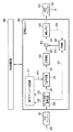
図1を参照すると、本発明の第1の実施形態に従う画像符号化装置では、動画像または静止画像の入力画像信号120が小画素ブロック単位、例えばマクロブロック単位に分割され、符号化ユニット100に入力される。ここでは、マクロブロックが符号化処理の基本的な処理ブロックサイズとされている。以下、入力画像信号120の符号化対象マクロブロックを単に対象ブロックという。(First embodiment)
Referring to FIG. 1, in the image encoding apparatus according to the first embodiment of the present invention, an
符号化ユニット100では、ブロックサイズや予測画像信号の生成方法の異なる複数の予測モードが用意されている。予測画像信号の生成方法は、具体的には大きく分けて符号化対象のフレーム内だけで予測画像を生成するフレーム内予測と、時間的に異なる複数の参照フレームを用いて予測を行うフレーム間予測がある。本実施形態では、説明を簡単にするために図2に示されているように左上から右下に向かって符号化処理がなされていくものとする。
In the
マクロブロックは、典型的に例えば図3に示すような16×16画素ブロックである。しかし、マクロブロックは32×32画素ブロック単位であっても8×8画素ブロック単位であってもよい。またマクロブロックの形状は、正方格子である必要は必ずしもない。 The macroblock is typically a 16 × 16 pixel block as shown in FIG. 3, for example. However, the macroblock may be a 32 × 32 pixel block unit or an 8 × 8 pixel block unit. The shape of the macroblock does not necessarily need to be a square lattice.
符号化ユニット100について説明する。減算器101では入力画像信号120と予測器102からの予測画像信号121との差がとられることにより、予測残差信号122が生成される。予測残差信号122は、モード判定部103及び変換器104に入力される。モード判定部103については後述する。変換器104では、予測残差信号122に対して例えば離散コサイン変換(DCT)のような直交変換が施されることにより、変換係数123が生成される。変換器104における変換には、離散サイン変換、ウェーブレット変換や、独立成分解析などの手法を用いてもよい。
The
変換器104から出力される変換係数123は、量子化器105へ入力される。量子化器105では、例えば符号化制御部113によって与えられる量子化パラメータと後述する量子化マトリクス変調部110によって生成される変調量子化マトリクス133に従って変換係数123が量子化され、量子化変換係数124が生成される。
The
量子化変換係数124は、逆量子化器106及びエントロピー符号化器111に入力される。エントロピー符号化器111については、後述する。逆量子化器106では、量子化変換係数124に対して、例えば符号化制御部113から与えられる量子化パラメータと変調量子化マトリクス133に従って逆量子化が施されることにより、逆量子化変換係数125が生成される。
The quantized
逆量子化器106からの逆量子化変換係数125に対して、逆変換器107において変換器104の変換と逆の変換、例えば逆離散コサイン変換(IDCT)のような逆直交変換が施される。この逆直交変換によって、予測残差信号122と同じ信号(復号予測残差信号という)126が再生される。復号予測残差信号126は、加算器108に入力される。加算器108では、復号予測残差信号126と予測器102からの予測画像信号121とが加算されることにより、局部復号信号127が生成される。局部復号信号127は、参照メモリ109に参照画像信号として蓄積される。参照メモリ109に蓄積された参照画像信号は、予測器102による予測の際に参照される。
The inverse quantized
予測器102では、参照メモリ107に蓄積された参照画像信号の画素(符号化済み参照画素)を利用して、フレーム間予測またはフレーム内予測が行われる。この結果、予測器102により対象ブロックに対して選択可能な全ての予測画像信号121が生成される。ただし、H. 264のフレーム内予測、例えば図4Aに示される4×4画素ブロックサイズ予測または図4Bに示される8×8画素ブロックサイズ予測のように、対象ブロック内で局部復号信号を作成しないと次の予測ができないような予測モードに関しては、予測器102の内部で変換/量子化及び逆量子化/逆変換を行ってもよい。
In the
予測器102における予測モードの例として、フレーム間予測について説明する。フレーム間予測で対象ブロックを予測する際、参照メモリ109に蓄積されている複数の符号化済み参照画素を用いてブロックマッチングが行われる。ブロックマッチングでは、原画像である入力画像信号120の対象ブロックの画素と複数の参照画素との間のずれ量が計算される。予測器102から、このずれ量を利用して予測された画像のうち原画像との差が小さい画像が予測画像信号121として出力される。このずれ量は整数画素精度や分数画素精度で計算され、このずれ量を示す情報が動きベクトル情報128として予測モード情報129に付加される。
As an example of the prediction mode in the
予測器102によって生成された予測画像信号121、及び前記予測残差信号122は、モード判定部103へ入力される。モード判定部103では、入力画像信号120、予測画像信号121、予測残差信号122、予測器102で用いた予測モードを表すモード情報129、及び後述する変調インデックス132に基づいて、最適な予測モードの選択(これをモード判定という)を行う。
The
より具体的に説明すると、モード判定部103は次式のようなコストを用いたモード判定を行う。予測モード情報129に関する符号量をOH、変調インデックス132の符号量をINDEX、入力画像信号120と局部復号信号127との間の差分絶対値和をSADとすると、モード判定部103は以下のモード判定式を用いる。
![]()
![]()
ここでKはコスト、λは定数をそれぞれ表す。λは量子化スケールや量子化パラメータの値に基づいて決められる。このようにして得られたコストKを基に、モード判定が行われる。すなわち、コストKが最も小さい値を与えるモードが最適な予測モードとして選択される。
Here, K represents a cost, and λ represents a constant. λ is determined based on the quantization scale and the value of the quantization parameter. The mode determination is performed based on the cost K obtained in this way. That is, the mode that gives the smallest value of cost K is selected as the optimal prediction mode.
モード判定部103においては、式(1)に代えて(a)予測モード情報129のみ、(b)変調インデックス132のみ、(c)SADのみ、または(d)予測残差信号122の絶対和のみを用いてモード判定を行ってもよいし、これら(a)(b)(c)及び(d)のいずれかにアダマール変換を施した値、またはそれに近似した値を利用してもよい。さらに、モード判定部103において入力画像信号120のアクテビティを用いてコストを作成してもよいし、量子化スケールまたは量子化パラメータを利用してコスト関数を作成してもよい。
In the
さらに別の例として、仮符号化ユニットを用意し、モード判定部103において仮符号化ユニットにより、ある予測モードで生成された予測残差信号122を実際に符号化した場合の符号量と、入力画像信号120と局部復号信号127との間の二乗誤差を用いてモード判定を行ってもよい。この場合のモード判定式は、以下のようになる。
![]()
![]()
ここで、Jは符号化コスト、Dは入力画像信号120と局部復号画像116との間の二乗誤差を表す符号化歪みである。一方、Rは仮符号化によって見積もられた符号量を表している。
Here, J is an encoding cost, and D is an encoding distortion representing a square error between the
式(2)の符号化コストJを用いると、予測モード毎に仮符号化と局部復号処理が必要となるため、回路規模または演算量は増大する。反面、より正確な符号量と符号化歪みを用いるため、高い符号化効率を維持することができる。式(2)に代えてRのみ、またはDのみを用いてコストを算出してもよいし、Rを近似した値またはDを近似した値を用いてコスト関数を作成してもよい。以下では、式(2)で示される符号化コストJを用いて説明を行う。 When the encoding cost J of Expression (2) is used, provisional encoding and local decoding processing are required for each prediction mode, so that the circuit scale or the amount of calculation increases. On the other hand, since a more accurate code amount and encoding distortion are used, high encoding efficiency can be maintained. The cost may be calculated using only R or only D instead of Equation (2), or the cost function may be created using a value approximating R or a value approximating D. Below, it demonstrates using the encoding cost J shown by Formula (2).
モード判定部103から出力される予測モード情報129(動きベクトル情報を含む)は、エントロピー符号化器111に入力される。エントロピー符号化器111では、量子化変換係数124、予測モード情報129、量子化マトリクス131及び変調マトリクス132などの情報に対して、エントロピー符号化、例えばハフマン符号化や算術符号化などが行われ、符号化データが生成される。
Prediction mode information 129 (including motion vector information) output from the
エントロピー符号化器111により生成された符号化データは符号化ユニット100から出力され、多重化を経て出力バッファ112に一旦蓄積される。出力バッファ112に蓄積された符号化データは、符号化制御部113が管理する出力タイミングに従って画像符号化装置の外部へ符号化ビットストリーム130として出力される。符号化ビットストリーム130は、図示しない蓄積系(蓄積メディア)または伝送系(通信ネットワーク)へ送出される。
The encoded data generated by the
(量子化マトリクス変調部110について)
量子化マトリクス変調部110では、符号化制御部113から与えられる量子化マトリクス131に対して、モード判定部103からの変調インデックス132に従って変調が施されることにより、変調量子化マトリクス133が生成される。変調量子化マトリクス133は量子化器105及び逆量子化器106に与えられ、量子化及び逆量子化に用いられる。(Regarding the quantization matrix modulator 110)
The quantization
より具体的に説明すると、変調量子化マトリクス133に従って量子化器105で行われる量子化は次式で表される。
![]()
![]()
ここでYは量子化変換係数124を表し、Xは量子化前の変換係数123を表す。fは量子化における切り上げ/切捨てを制御する丸めオフセットである。Qstepは量子化スケール(量子化ステップサイズ、もしくは量子化幅ともいう)を表している。Qstepの値が大きいときは粗く量子化が行われ、小さいときは細かく量子化が行われる。Qstepは、量子化パラメータに基づいて変更される。(i,j)は量子化器105における量子化ブロック内の周波数成分位置をxy座標で表している。(i,j)は量子化ブロックが図5Aで示される4×4画素ブロックであるか、図5Bで示される8×8画素ブロックであるかなどによって異なる。
Here, Y represents the quantized
一般的に、変換ブロックサイズと量子化ブロックサイズは一致している。本実施形態では、複数のブロックサイズの変換量子化ブロックサイズを持っている。変換量子化ブロックサイズは異なる予測モードとして設定されており、異なる予測モードとしてモード判定部103で判断される。
In general, the transform block size and the quantization block size are the same. In the present embodiment, a plurality of block quantization block quantization block sizes are provided. The transform quantization block size is set as a different prediction mode, and is determined by the
式(3)中のMQMは変調量子化マトリクス133を表し、idxは変調インデックス132を表している。変調インデックス132は、量子化マトリクス変調部110により行われる量子化マトリクス131の変調に関するインデックスである。変調インデックス132については、後に詳しく説明する。
MQM in equation (3) represents the
変換係数123の符号を分離する場合、式(3)は以下のように変形される。
![]()
![]()
ここで、sign(X)はXの符号を返す関数であり、変換係数123の符号を表す。abs(X)はXの絶対値を返す関数である。
Here, sign (X) is a function that returns the sign of X and represents the sign of the
演算を簡単化するため、量子化スケールQstepを2のべき乗で設計すると、式(3)は以下のように変形される。

ここで、Qbitは2のべき乗で設計された量子化スケールを表している。
Here, Q bit represents a quantization scale designed to be a power of 2.
この場合、除算をビットシフトで置き換えることが可能となり、除算に必要な処理量を軽減することができる。 In this case, division can be replaced with bit shift, and the amount of processing necessary for division can be reduced.
演算精度をできるだけ抑えるために、周波数成分毎に演算精度を変更することも可能である。この場合、式(3)は以下のように変形される。
ここで、LSは量子化処理の演算精度を周波数成分毎に調整するための演算精度制御パラメータである。すなわち、LSは量子化処理を行う際に周波数位置毎に演算のスケールを変えるために用いられ、レベルスケール(LevelScale)またはノルムアジャスト(normAdjust)などと呼ばれる。演算精度制御パラメータLSは、変換係数の高周波成分(図5A及び図5Bのそれぞれの右下の領域)に絶対値の大きい値が発生する確率が低い性質を利用している。量子化と逆量子化で演算のスケールを合わせられるように、LSと後述するILSを設計する必要がある。
Here, LS is a calculation accuracy control parameter for adjusting the calculation accuracy of the quantization process for each frequency component. That is, LS is used to change the scale of calculation for each frequency position when performing quantization processing, and is called level scale (LevelScale) or norm adjust (normAdjust). The calculation accuracy control parameter LS utilizes the property that the probability that a large absolute value is generated in the high-frequency component of the conversion coefficient (the lower right region in FIGS. 5A and 5B) is low. It is necessary to design LS and ILS (to be described later) so that the operation scale can be adjusted by quantization and inverse quantization.
次に、量子化マトリクス変調部110から出力される変調量子化マトリクス133について説明する。変調される前の量子化マトリクス131は、変換係数123の周波数成分毎に量子化の粗さを変えることが可能なマトリクスである。4×4画素ブロックに対応する量子化マトリクス131の例を次式に示す。
図5Aと式(7)の周波数成分(i,j)は1対1に対応しており、右下の値ほど高い周波数成分に対するマトリクス値を示している。例えば、周波数位置(0,3)のマトリクス値は28となっている。量子化マトリクス131と変調量子化マトリクス133の関係は次式で表される。
![]()
The frequency components (i, j) in FIG. 5A and the equation (7) have a one-to-one correspondence, and the lower right value indicates the matrix value for the higher frequency component. For example, the matrix value of frequency position (0, 3) is 28. The relationship between the
![]()
ここで、QMは量子化マトリクス131を表し、MQMは変調量子化マトリクス133を表している。MPは、変調強度を示す変調パラメータを表している。この場合、変調インデックス132は式(8)に示すような変調方法(量子化マトリクスを変調パラメータの加算によって変調するという方法)と変調パラメータMPを指し示す。なお、変調インデックス132は、このような変調方法が記述されたテーブルの番号であってもよい。
Here, QM represents the
式(8)では量子化マトリクスQMと変調パラメータMPを加算することによってQMを変調する例を示しているが、他にQMとMPとの間で減算、乗算、除算またはビットシフトなどを行ってQMを変調してもよい。 Equation (8) shows an example in which the QM is modulated by adding the quantization matrix QM and the modulation parameter MP, but other subtraction, multiplication, division, bit shift, etc. are performed between the QM and MP. QM may be modulated.
一方、量子化マトリクスQMに対して周波数成分毎に異なる変調を行う場合は、次式が用いられる。
![]()
![]()
ここで、MMは変調マトリクスを表している。この場合、変調インデックス132は式(9)に示すような変調方法(量子化マトリクスを変調マトリクスの加算によって変調するという方法)と変調マトリクスMMを指し示す。なお、変調インデックス132は、このような変調方法が記述されたテーブルの番号であってもよい。
Here, MM represents a modulation matrix. In this case, the
ここでは量子化マトリクスQMと変調マトリクスMMを加算することによってQMを変調する例を示しているが、他にQMとMMとの間で減算、乗算、除算またはビットシフトなどを行ってQMを変調してもよい。式(8)は、式(9)の変調マトリクスMMの全成分が同じ値を取ることと同義である。 Here, an example is shown in which the QM is modulated by adding the quantization matrix QM and the modulation matrix MM, but the QM is also modulated by performing subtraction, multiplication, division or bit shift between the QM and MM. May be. Expression (8) is synonymous with the fact that all components of the modulation matrix MM in Expression (9) have the same value.
式(10)は、4×4サイズの量子化ブロックに対する変調マトリクスMMの例を示している。変調マトリクスMMも量子化マトリクスQMと同様、図5Aで示される周波数位置の関係と1対1に対応している。
量子化マトリクスQMが周波数成分に対して固定値の場合は、式(10)に代えて次式を用いてもよい。
![]()
When the quantization matrix QM is a fixed value with respect to the frequency component, the following equation may be used instead of the equation (10).
![]()
ここで、QMはQM(i,j)の全成分が同じ値を取ることを示している。
Here, QM indicates that all components of QM (i, j) have the same value.
変調パラメータMP及び変調マトリクスMMは、量子化マトリクスQMに変調を施すために導入されている。QMの変調を行わない場合、またはMPが0、またはMMの全成分が0の場合、MQMは次式で算出されることと同義である。
![]()
![]()
量子化マトリクスQMの変調を行わない場合、次式に示される変調マトリクスMMを式(9)に代入しても式(12)と同じ結果が得られる。
When the quantization matrix QM is not modulated, the same result as in Expression (12) can be obtained even if the modulation matrix MM shown in the following expression is substituted into Expression (9).
このようにして、量子化器105において変調量子化マトリクス133(MM)を用いた量子化が行われる。ここでは、量子化マトリクス変調部110に符号化制御部113から量子化マトリクス131が入力パラメータとして与えられるとしたが、量子化マトリクス変調部110に量子化マトリクス131が与えられなくてもよい。その場合、量子化マトリクス変調部110に予め決められた初期量子化マトリクス、例えば次式で示されるようなマトリクスQMInt(i,j)が設定される。
In this manner, the
式(14)では初期量子化マトリクスQMInt(i,j)の全ての値が16である例を示したが、他の値でもよいし、周波数成分毎に異なる値を設定していてもよい。画像符号化装置と画像復号化装置間で予め決められた同じ初期量子化マトリクスが設定されればよい。
Expression (14) shows an example in which all values of the initial quantization matrix QM Int (i, j) are 16, but other values may be used, or different values may be set for each frequency component. . The same initial quantization matrix determined in advance between the image encoding device and the image decoding device may be set.
量子化及び逆量子化に必要とされる量子化パラメータは、符号化制御部113において設定されている。量子化器105で及び逆量子化器106で利用される量子化パラメータは、1対1に対応している。量子化器105から出力された量子化変換係数124は、変調量子化マトリクス133と共に逆量子化器106へ入力される。逆量子化器106では、量子化器105から与えられる量子化変換係数124に対して、変調量子化マトリクス133と量子化パラメータを用いて逆量子化が行われる。式(3)の量子化に対応する逆量子化は、次式で表される。
ここで、Yは量子化変換係数124、X’は逆量子化変換係数125を表し、MQMは量子化時に利用された変調量子化マトリクス132を表している。
Here, Y represents a quantized
式(4)の量子化に対応する逆量子化は、次式で表される。
ここで、sign(Y)はYの符号を返す関数である。
Here, sign (Y) is a function that returns the sign of Y.
演算を簡単化するため、Qstepを2のべき乗とすると、式(5)に対応する逆量子化は次式で表される。
式(17)によると、乗算をビットシフトで置き換えることが可能となり、乗算に必要な処理量を軽減することができる。
According to Equation (17), multiplication can be replaced with bit shift, and the amount of processing necessary for multiplication can be reduced.
一方、演算精度を抑えるために周波数成分毎に演算精度を変更する、式(6)に対応した逆量子化は次式で示される。
ここで、ILSは逆量子化処理の演算精度を周波数成分毎に調整するための演算精度制御パラメータである。ILSは逆量子化処理を行う際に、周波数位置毎に演算のスケールを変えるために用いられ、レベルスケール(LevelScale)またはノルムアジャスト(normAdjust)などと呼ばれる。ILSとしては、量子化で利用した演算精度制御パラメータに対応する値が用いられる。H. 264 ハイプロファイルの逆量子化(誤差信号4×4画素ブロック)を次式に示す。すなわち、H. 264では少ない演算量で16ビットでの演算精度を実現するために、次式のような逆量子化が行われる。
![]()
Here, ILS is a calculation accuracy control parameter for adjusting the calculation accuracy of the inverse quantization process for each frequency component. The ILS is used to change the scale of calculation for each frequency position when performing inverse quantization processing, and is called a level scale (LevelScale) or a norm adjust (normAdjust). As the ILS, a value corresponding to the calculation accuracy control parameter used in the quantization is used. H. 264 High profile inverse quantization (error signal 4 × 4 pixel block) is shown in the following equation. That is, in H.264, inverse quantization as shown in the following equation is performed in order to realize calculation accuracy with 16 bits with a small calculation amount.
![]()
ここで、レベルスケールILS(m,i,j)は式(20)で定義される値であり、QPは0から51までの値をとる量子化パラメータである。
Here, the level scale ILS (m, i, j) is a value defined by the equation (20), and QP is a quantization parameter that takes a value from 0 to 51.
ここで、Norm(m,i,j)は式(5)で表されるスケール調整パラメータであり、各要素は式(6)で表されている。
Here, Norm (m, i, j) is a scale adjustment parameter represented by Expression (5), and each element is represented by Expression (6).
量子化器105で量子化時に利用された量子化パラメータは、逆量子化器106に対しても、符号化制御部113によって設定される。これによって、量子化器105及び逆量子化器106の双方で必ず同じ量子化パラメータが利用される。さらに、量子化器105及び逆量子化器106では、同じ変調量子化マトリクス133が利用される。
The quantization parameter used at the time of quantization by the
図1における減算器101→変換器104→量子化器105→逆量子化器106→逆変換器107→加算器108→参照メモリ109のループを符号化ループと呼ぶ。符号化ループは、対象ブロックで選択可能な1つの予測モードと、1つの変調インデックスと、1つのブロックサイズとの組み合わせに対して処理を行った場合に一巡する。ここでいう組み合わせは、具体的には例えばイントラ予測モードと変調インデックス0と8x8ブロックサイズとの組み合わせ、インター予測モードと変調インデックス0と4x4ブロックサイズとの組み合わせなどを指す。対象ブロックに対して、このような符号化ループの処理が複数回行われ、取り得る全ての組み合わせが終了すると、次のブロックの入力画像信号120が入力され、次の符号化が行われる。
The loop of the
符号化制御部113は、発生符号量のフィードバック制御、量子化特性制御及びモード判定制御などを行うことによって、発生符号量の制御を行うレート制御、予測器102の制御、外部入力パラメータの制御といった符号化の処理全般の制御を行う。符号化制御部113は、さらに出力バッファ112の制御を行い、適切なタイミングで符号化ビットストリーム130を外部に出力させる機能を有する。
The
符号化ユニット100及び符号化制御部113の処理は、ハードウェアにより実現することも可能であるが、コンピュータを用いてソフトウェア(プログラム)によって実現することも可能である。
The processing of the
(量子化マトリクス変調部110の具体例)
次に、量子化マトリクス変調部110の具体例を説明する。図6に示されるように、量子化マトリクス変調部110は変調マトリクス設定部201と変調量子化マトリクス生成部202を有する。図1中のモード判定部103から出力される変調インデックス132は、変調マトリクス設定部201へ入力される。図1中の符号化制御部113から入力パラメータとして設定される、または予め保持されている量子化マトリクス131は、変調量子化マトリクス生成部202へ入力される。(Specific Example of Quantization Matrix Modulation Unit 110)
Next, a specific example of the quantization
変調マトリクス設定部201では、変調インデックス132に対応する変調マトリクス134が変調量子化マトリクス生成部202に対して設定される。変調量子化マトリクス生成部202では、量子化マトリクス131に対して変調マトリクス134を用いて変調が施されることにより、変調量子化マトリクス133が生成される。生成された変調量子化マトリクス133は、量子化マトリクス変調部110から出力される。
In the modulation
(変調マトリクス設定部201)
図7に示されるように、変調マトリクス設定部201は、切替器301と、生成方法または変調パラメータの異なる変調マトリクス生成部302,303及び304を有する。切替器301は、入力されてきた変調インデックス132の値に応じて切り替わり、変調マトリクス生成部302,303及び304のいずれか一つをアクティブにする機能を有する。例えば、変調インデックス132がidx=0であるとき、切替器301は変調マトリクス生成部302を動作させる。同様に、切替器301はidx=1のときは変調マトリクス生成部303を動作させ、idx=N−1のときは変調マトリクス生成部304を動作させる。動作した変調マトリクス生成部によって変調マトリクス134が生成される。生成された変調マトリクス134は、変調量子化マトリクス生成部202に対して設定される。(Modulation matrix setting unit 201)
As illustrated in FIG. 7, the modulation
変調マトリクス134の具体的な生成方法を説明する。ここでは、変調マトリクス134の生成のための2つの生成モデルについて示す。以下、変調マトリクス134の生成方法を変調モデルと呼ぶ。式(24)及び式(25)に示されるような変調マトリクス134の成分の、第1行第1列の成分からの距離を市街地距離として次式で定義する。
![]()
![]()
例えば、図5Aにおいて(i,j)=(3,3)に位置する周波数成分の距離は6となる。一方、図5Bに示されるような8×8ブロックの場合、(i,j)=(3,7)に位置する周波数成分の距離は10となる。
For example, in FIG. 5A, the distance between the frequency components located at (i, j) = (3,3) is 6. On the other hand, in the case of an 8 × 8 block as shown in FIG. 5B, the distance between the frequency components located at (i, j) = (3, 7) is 10.
本実施形態のように変調マトリクス134が量子化マトリクス131に加算される例では、量子化マトリクス131及び変調マトリクス134の各周波数成分は1対1に対応する。つまりrの値(変調マトリクス134のマトリクス値)が大きくなるほど、高周波数成分に対する変調を行い、rが小さければ低周波数成分に対する変調を行う。以下、量子化マトリクス131を変調するための変調モデルについて説明する。
In the example in which the
図8は、線形関数で定義される変調モデルであり、次式で表される。
式(24)中のaは変調の強度を制御するパラメータである。以後、このパラメータaを変調制御パラメータと呼ぶ。変調制御パラメータaは、正の値を取るときは図8中の第1象限に値を持ち、負の値を取るときは第4象限に値を持つ。これにより変調制御パラメータaが大きな値を持つほど、高周波成分に対して強い変調が施される。
In the equation (24), “a” is a parameter for controlling the intensity of modulation. Hereinafter, the parameter a is referred to as a modulation control parameter. The modulation control parameter a has a value in the first quadrant in FIG. 8 when taking a positive value, and has a value in the fourth quadrant when taking a negative value. As a result, the higher the modulation control parameter a is, the stronger the high frequency component is modulated.
図9は、線形関数とサイン関数を用いた場合の変調モデルであり、次式で表される。
![]()
![]()
式(25)中のb,cはaと同様に変調制御パラメータである。サイン関数は、線形関数に対して歪みを加える項となっている。変調制御パラメータcは、サイン関数の変化の周期を制御するパラメータである。変調制御パラメータbは、歪みの強さを制御するパラメータである。
In Expression (25), b and c are modulation control parameters as in a. The sine function is a term that adds distortion to the linear function. The modulation control parameter c is a parameter that controls the period of change of the sine function. The modulation control parameter b is a parameter that controls the strength of distortion.
ここでは、変調モデルとして線形関数モデルまたはサイン関数モデルを用いた例を示しているが、変調モデルの別の例として対数モデル、自己相関関数モデル、比例・逆比例モデル、N次関数(N≧1)モデル、またはガウス関数やラプラス関数を含む一般化ガウス関数モデルなどを用いてもよい。いずれのモデルを用いる場合も、画像符号化装置において利用された変調と同じ変調が画像復号化装置においても利用できることが重要であるが、これは画像符号化装置において変調インデックス132により変調モデルを指し示すようにすることにより可能となる。
Here, an example using a linear function model or a sine function model as a modulation model is shown, but as another example of the modulation model, a logarithmic model, an autocorrelation function model, a proportional / inverse proportional model, an Nth order function (N ≧ 1) A model or a generalized Gaussian function model including a Gaussian function or a Laplace function may be used. In any of the models, it is important that the same modulation as that used in the image coding apparatus can be used in the image decoding apparatus. This indicates the modulation model by the
変調マトリクス生成部302,303及び304は便宜上、それぞれインデックス0,インデックス1及びインデックスN−1に対応させている。しかし変調マトリクス生成部をインデックス数Nの値に応じて用意してもよいし、インデックスの異なる値に対して同じ変調マトリクス生成部を利用してもよい。例えば、表1〜表3は変調インデックス132に対する変調モデルと変調制御パラメータの組み合わせ例を示している。
表1〜表3中、N/Aで示される記号は、現在規定されている変調モデルでは対象パラメータを利用しないことを意味している。インデックス0は、変調を行わない場合、すなわち式(12)を利用する場合を示している。
In Tables 1 to 3, the symbol denoted by N / A means that the target parameter is not used in the currently specified modulation model.
表1は、変調インデックスが2ビット(N=4通り)で規定されている場合の変調モデルと変調制御パラメータの組み合わせ例である。この場合、式(24)で示される変調モデルのみを利用するため、図7中の変調マトリクス生成部は1つのみでよい。変調インデックスに応じて、予め設定されている変調制御パラメータaが読み出され、変調マトリクスが生成される。 Table 1 shows a combination example of the modulation model and the modulation control parameter when the modulation index is defined by 2 bits (N = 4). In this case, since only the modulation model represented by Expression (24) is used, only one modulation matrix generation unit in FIG. 7 is required. A preset modulation control parameter a is read according to the modulation index, and a modulation matrix is generated.
表2は、変調インデックスが3ビット(N=8通り)で規定され、且つ複数の変調モデルを用いたときの例を示している。この場合、式(24)及び式(25)の2つの変調モデルを利用している。表1と同様、予め決められた変調制御パラメータに応じて変調マトリクスが生成される。 Table 2 shows an example when the modulation index is defined by 3 bits (N = 8) and a plurality of modulation models are used. In this case, two modulation models of Expression (24) and Expression (25) are used. Similar to Table 1, a modulation matrix is generated according to a predetermined modulation control parameter.
表1で示されるように、1つの変調制御パラメータのみで表現される変調モデルを用いている場合、変調インデックスの値を変調制御パラメータに直接対応付けてもよい。この場合の例は、表3に示されている。表1及び表2の対応付けでは、予め定められたテーブルに従って変調マトリクスが生成されるのに対し、表3の場合は量子化マトリクスの変調の強度を直接変更することが可能となる。すなわち、予め設定しておく必要がなく、必要に応じて大きな値を直接設定して変調マトリクスを生成することが可能である。 As shown in Table 1, when a modulation model expressed by only one modulation control parameter is used, the value of the modulation index may be directly associated with the modulation control parameter. An example of this case is shown in Table 3. In the correspondence between Table 1 and Table 2, the modulation matrix is generated according to a predetermined table, whereas in Table 3, the modulation intensity of the quantization matrix can be directly changed. That is, it is not necessary to set in advance, and it is possible to generate a modulation matrix by directly setting a large value as necessary.
(変調量子化マトリクス生成部202)
図10に示されるように、変調量子化マトリクス生成部202は算術演算器501を有する。算術演算器401は、加算を始めとして、減算、乗算、除算及びビットシフトなどの基本演算を行うことができる。また、これらの基本演算を組み合わせて、行列の加算、減算、乗算及び除算なども可能である。(Modulation quantization matrix generation unit 202)
As shown in FIG. 10, the modulation quantization
算術演算器401では、変調マトリクス設定部203からの変調マトリクスと符号化制御部113からの量子化マトリクス131が入力され、量子化マトリクス131に対して変調が施される。本実施形態では、式(9)で示されるような変調マトリクス(MM)の加算によって量子化マトリクス131が変調され、変調量子化マトリクス133が生成される。生成された変調量子化マトリクス133は、変調量子化マトリクス生成部202から出力される。
The
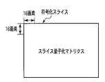
次に、量子化マトリクスの変調について図11A、図11B、図11C及び図11Dを用いて説明する。図11Aは、式(12)のように変調マトリクスを利用しない場合に、それぞれのマクロブロックに割り当てられる量子化マトリクスを示している。この場合、符号化スライスの全てのマクロブロックに対して同じ量子化マトリクス131が適用されるため、図11Aでは量子化マトリクスをスライス量子化マトリクスと記載している。
Next, modulation of the quantization matrix will be described with reference to FIGS. 11A, 11B, 11C, and 11D. FIG. 11A shows a quantization matrix assigned to each macroblock when the modulation matrix is not used as in Expression (12). In this case, since the
一方、図11Bは2つの変調マトリクスを用いた場合(N=2)の例を示している。また、図11Dは図11Cに示される4つの変調マトリクスを用いた場合(N=4)の例を示している。図11Cは、量子化マトリクス131に対して変調マトリクス設定部203で設定された4つの変調マトリクス203が示されている。変調量子化マトリクス生成部202において式(9)に示したような変調マトリクス(MM)の加算による変調を行うことによって、図11B及び図11Dに示すように符号化スライス内の局所的な領域で特性の異なる量子化マトリクス(ブロック量子化マトリクスという)を生成することができる。これによって、符号化スライス内の局所的な領域で異なる量子化マトリクスを適用することが可能となる。
On the other hand, FIG. 11B shows an example in which two modulation matrices are used (N = 2). FIG. 11D shows an example in which the four modulation matrices shown in FIG. 11C are used (N = 4). FIG. 11C shows four modulation matrices 203 set by the modulation matrix setting unit 203 for the
(符号化処理手順)
次に、図12を用いて本実施形態における画像符号化の処理手順について説明する。画像符号化装置に動画像信号が入力されると、符号化対象の動画像フレーム1枚が読み込まれ(ステップS001)、読み込まれた動画像フレームが複数のマクロブロックに分割され、マクロブロック単位の入力画像信号120が符号化ユニット100に入力される(ステップS002)。このとき、モード判定部103では予測モード:modeと変調インデックス132:indexの初期化及び符号化コスト:min_costの初期化が行われる(ステップS003)。(Encoding procedure)
Next, a processing procedure of image encoding in the present embodiment will be described with reference to FIG. When a moving image signal is input to the image encoding device, one moving image frame to be encoded is read (step S001), and the read moving image frame is divided into a plurality of macroblocks. The
次に、予測器102において入力画像信号120を用いて、対象ブロックに対して選択可能な1つのモードにおける予測画像信号121が生成される(ステップS004)。図12では省略しているが、次に入力画像信号120と生成された予測画像信号121との差分がとられ、予測残差信号122が生成される。生成された予測残差信号122は、変換器104によって直交変換される(ステップS006の前半)。この直交変換により生成された変換係数123は、量子化器105へ入力される。
Next, the
一方、モード判定部103で選択された変調インデックス132:indexの値に応じて変調マトリクスが設定される(ステップS005)。設定された変調マトリクスを用いて量子化マトリクス変調部110により変調量子化マトリクス132が生成され、変調量子化マトリクス132を用いて量子化器105により変換係数123の量子化が行われる(ステップS006の後半)。ここでは符号化歪Dと符号量Rの算出を行い、式(3)を用いて符号化コスト:costを計算する(ステップS007)。
On the other hand, a modulation matrix is set according to the value of the modulation index 132: index selected by the mode determination unit 103 (step S005). A
モード判定部103は、計算された符号化コスト:costが最小コスト:min_costより小さいか否かを判別する(ステップS008)。costが最小コスト:min_costより小さい場合(S008の結果がYESの場合)には、costでmin_costを更新するとともに、その際の予測モードをbest_modeとして保持し、さらにそのときの変調インデックス132:indexをbest_indexとして保持する(ステップS009)。同時に、予測画像信号121を内部メモリに一時保持する(ステップS010)。
The
一方、costが最小コストであるmin_costより大きい場合(S008の結果がNOの場合)には、変調インデックス132:indexをインクリメントし、インクリメント後のindexが変調インデックス132の最後かどうかを判定する(ステップS011)。indexが変調インデックス132の最後の番号であるIMAXよりも大きい場合(S011の結果がYESの場合)、best_indexの情報がエントロピー符号化器111へ渡される。一方、indexがIMAXよりも小さい場合(S011の結果がNOの場合)には、更新された変調インデックスindexを用いて再度、前記符号化ループの処理が実行される。
On the other hand, if the cost is greater than the minimum cost min_cost (if the result of S008 is NO), the modulation index 132: index is incremented, and it is determined whether the incremented index is the last of the modulation index 132 (step). S011). When index is larger than IMAX which is the last number of modulation index 132 (when the result of S011 is YES), the information of best_index is passed to
ステップS010の結果がYESの場合、次に予測モード:modeをインクリメントし、インクリメント後のmodeが予測モードの最後であるかどうかを判定する(ステップS012)。modeが予測モードの最後の番号であるMMAXよりも大きい場合(S012の結果がYESの場合)、best_modeの予測モード情報及び量子化された変換係数123がエントロピー符号化器111へ送られ、変換係数111と既に確定している変調インデックス132のエントロピー符号化が行われる(ステップS013)。一方、modeがMMAXよりも小さい場合(S012の結果がNOの場合)、次のmodeで示される予測モードに対して前記符号化ループの処理が行われる。
If the result of step S010 is YES, the prediction mode: mode is then incremented, and it is determined whether the mode after the increment is the last of the prediction modes (step S012). When mode is larger than MMAX which is the last number of the prediction mode (when the result of S012 is YES), the prediction mode information of best_mode and the
best_mode及びbest_indexでの符号化が行われると、量子化変換係数124が逆量子化器106へ入力され、量子化時に利用された変調インデックスと同じbest_indexによって逆量子化が行われる(ステップS014の前半)。更に逆量子化された変換係数125は逆変換器107へ入力され、逆変換が行われる(ステップS014の後半)。再生された予測残差信号126とモード判定部103から提供されるbest_modeの予測画像信号124とが加算され、これによって生成される復号画像信号127が参照メモリ109へ保存される(ステップS015)。
When encoding with best_mode and best_index is performed, the quantized
ここで、1フレームの符号化処理が終了しているかどうかの判定が行われる(ステップS016)。処理が完了している場合(S016の結果がYESの場合)、次のフレームの画像信号が入力され、符号化処理が行われる。一方、1フレームの符号化処理が完了していない場合(S016の結果がNOの場合)、次の対象ブロックの画像信号が入力され、符号化処理が継続される。 Here, it is determined whether or not the encoding process for one frame has been completed (step S016). When the process is completed (when the result of S016 is YES), the image signal of the next frame is input and the encoding process is performed. On the other hand, when the encoding process for one frame is not completed (when the result of S016 is NO), the image signal of the next target block is input, and the encoding process is continued.
(シンタクスの符号化方法)
次に、本実施形態で用いるシンタクスの符号化方法について説明する。図13は、本実施形態で用いられるシンタクスの構造の概略を示している。シンタクスは主に3つのパートからなる。ハイレベルシンタクス501では、スライス以上の上位レイヤのシンタクス情報が詰め込まれている。スライスレベルシンタクス502では、スライス毎に必要な情報が明記されており、マクロブロックレベルシンタクス503では、マクロブロック毎に必要とされる量子化パラメータの変更値やモード情報などが明記されている。(Syntax coding method)
Next, a syntax encoding method used in the present embodiment will be described. FIG. 13 shows an outline of the syntax structure used in this embodiment. The syntax mainly consists of three parts. In the high-
シクタクス501〜503は、さらに詳細なシンタクスで構成されている。ハイレベルシンタクス501は、シーケンスパラメータセットシンタクス504とピクチャパラメータセットシンタクス505などのシーケンスレベル及びピクチャレベルのシンタクスを含む。スライスレベルシンタクス502は、スライスヘッダシンタクス506及びスライスデータシンタクス507などを含む。マクロブロックレベルシンタクス503は、マクロブロックレイヤーシンタクス508及びマクロブロックプレディクションシンタクス509などを含む。
The
本実施形態において必要となるシンタクス情報は、シーケンスパラメータセットシンタクス504、ピクチャパラメータセットシンタクス505、スライスヘッダシンタクス506及びマクロブロックレイヤーシンタクス508であり、以下これらの各シンタクス504〜506について説明する。
The syntax information required in the present embodiment is a sequence parameter set
図14のシーケンスパラメータセットシンタクス内に示されるseq_moduletaed_quantization_matrix_flagは、量子化マトリクスの変調の可否、すなわち量子化器105が変調量子化マトリクス133を用いて量子化を行うか否か(変調前の量子化131を用いて量子化を行うか)をシーケンス毎に変更するかどうかを示すフラグである。当該フラグseq_moduletaed_quantization_matrix_flagがTRUEであるときは、量子化マトリクスの変調を利用するかどうかをシーケンス単位で切り替えることが可能である。一方、当該フラグseq_moduletaed_quantization_matrix_flagがFALSEであるときは、シーケンス内では量子化マトリクスの変調を用いることができない。
Seq_moduletaed_quantization_matrix_flag shown in the sequence parameter set syntax of FIG. 14 indicates whether or not the quantization matrix can be modulated, that is, whether or not the
図15のピクチャパラメータセットシンタクス内に示されるpic_moduletaed_quantization_matrix_flagは、量子化マトリクスの変調の利用可否をピクチャ毎に変更するかどうかを示すフラグである。当該フラグpic_moduletaed_quantization_matrix_flagがTRUEであるときは、量子化マトリクスの変調を利用するかどうかをピクチャ単位で切り替えることが可能である。一方、当該フラグpic_moduletaed_quantization_matrix_flagがFALSEであるときは、ピクチャ内では量子化マトリクスの変調を用いることができない。 The pic_moduletaed_quantization_matrix_flag shown in the picture parameter set syntax of FIG. 15 is a flag indicating whether or not to change the quantization matrix modulation availability for each picture. When the flag pic_moduletaed_quantization_matrix_flag is TRUE, it is possible to switch whether to use quantization matrix modulation on a picture-by-picture basis. On the other hand, when the flag pic_moduletaed_quantization_matrix_flag is FALSE, modulation of a quantization matrix cannot be used in a picture.
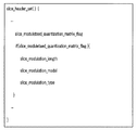
図16のスライスヘッダシンタクス内に示されるslice_moduletaed_quantization_matrix_flagは、量子化マトリクスの変調の利用可否をスライス毎に変更するかどうかを示すフラグである。当該フラグslice_moduletaed_quantization_matrix_flagがTRUEであるときは、量子化マトリクスの変調を利用するかどうかを、スライス単位で切り替えることが可能である。一方、当該フラグslice_moduletaed_quantization_matrix_flagがFALSEであるときは、スライス内では量子化マトリクスの変調を用いることができない。 The slice_moduletaed_quantization_matrix_flag shown in the slice header syntax of FIG. 16 is a flag indicating whether or not the use of quantization matrix modulation is changed for each slice. When the flag slice_moduletaed_quantization_matrix_flag is TRUE, whether to use quantization matrix modulation can be switched in units of slices. On the other hand, when the flag slice_moduletaed_quantization_matrix_flag is FALSE, quantization matrix modulation cannot be used in the slice.
図17のマクロブロックレイヤーシンタクス内に示されるmodulation_indexは、変調インデックスを表している。シンタクス中のcoded_block_patternは、当該ブロックに変換係数が発生しているかを示すインデックスである。当該インデックスcoded_block_patternが0である場合、当該マクロブロック内では変換係数が発生しないため、復号化の際に逆量子化を行う必要が無い。このような場合は、量子化マトリクスに関する情報を送る必要性がないため、modulation_indexは送信されない。 The modulation_index shown in the macroblock layer syntax in FIG. 17 represents the modulation index. The coded_block_pattern in the syntax is an index indicating whether a conversion coefficient is generated in the block. When the index coded_block_pattern is 0, no transform coefficient is generated in the macroblock, so that it is not necessary to perform inverse quantization at the time of decoding. In such a case, modulation_index is not transmitted because there is no need to send information about the quantization matrix.
一方、シンタクス中のmodeは、予測モードを示すインデックスである。当該インデックスmodeがskipモードを選択している場合、当該ブロックは同様に変換係数を送信しない。よってmodulation_indexは送信されない。CurrentModulatedQuantizationMatrixFlagは、seq_moduletaed_quantization_matrix_flag, pic_moduletaed_quantization_matrix_flag及びslice_moduletaed_quantization_matrix_flagの少なくとも1つのフラグがTRUEであるときにTRUEとなり、この条件が満たされない場合はFALSEを取る。当該フラグCurrentModulatedQuantizationMatrixFlagがFALSEであるとき、modulation_indexは送信されず、変調インデックス132には0に対応する値が設定される。modulation_indexは表1及び表2に示されるように、インデックス毎に変調モデルと変調制御パラメータが決められたテーブルを予め持っている。
On the other hand, mode in the syntax is an index indicating a prediction mode. When the index mode selects the skip mode, the block does not transmit the transform coefficient in the same manner. Therefore, modulation_index is not transmitted. CurrentModulatedQuantizationMatrixFlag becomes TRUE when at least one flag of seq_moduletaed_quantization_matrix_flag, pic_moduletaed_quantization_matrix_flag and slice_moduletaed_quantization_matrix_flag is TRUE, and takes FALSE when this condition is not satisfied. When the flag CurrentModulatedQuantizationMatrixFlag is FALSE, modulation_index is not transmitted, and the
図17で示されるmacroblock_dataシンタクスを図18で表されるようなシンタクスに変更してもよい。図18のシンタクスでは、図17のシンタクスにおけるmodulation_indexに代えてmodulation_strengthが送信される。modulation_indexは、前述したように変調モデルと変調制御パラメータが決められたテーブルを予め持っている。一方で、modulation_strengthは変調モデルが固定されており、その変調制御パラメータの値が直接送信される。すなわち、図18のシンタクスは表3で説明した方式に対応している。この場合、modulation_strengthを送信するための送信符号量は一般に増大する反面、量子化マトリクスの変調強度を変更するための自由度が高いため、より柔軟な量子化が可能となる。よって、符号量と復号画像のバランスを考えて図17のシンタクスと図18のシンタクスのいずれかを選択すればよい。 The macroblock_data syntax shown in FIG. 17 may be changed to the syntax shown in FIG. In the syntax of FIG. 18, modulation_strength is transmitted instead of modulation_index in the syntax of FIG. As described above, modulation_index has a table in which a modulation model and modulation control parameters are determined in advance. On the other hand, modulation_strength has a fixed modulation model, and the value of the modulation control parameter is directly transmitted. That is, the syntax in FIG. 18 corresponds to the method described in Table 3. In this case, although the amount of transmission code for transmitting modulation_strength generally increases, the degree of freedom for changing the modulation intensity of the quantization matrix is high, so that more flexible quantization is possible. Therefore, it is only necessary to select one of the syntax in FIG. 17 and the syntax in FIG. 18 in consideration of the balance between the code amount and the decoded image.
図18におけるCurrentModulatedQuantizationMatrixFlagは、seq_moduletaed_quantization_matrix_flag, pic_moduletaed_quantization_matrix_flag及びslice_moduletaed_quantization_matrix_flagの少なくとも1つのフラグがTRUEであるときにTRUEとなり、この条件が満たされない場合はFALSEを取る。当該フラグCurrentModulatedQuantizationMatrixFlagがFALSEであるとき、modulation_strengthは送信されず、変調インデックス132には0に対応する値が設定される。
CurrentModulatedQuantizationMatrixFlag in FIG. 18 is TRUE when at least one flag of seq_moduletaed_quantization_matrix_flag, pic_moduletaed_quantization_matrix_flag and slice_moduletaed_quantization_matrix_flag is TRUE, and takes FALSE when this condition is not satisfied. When the flag CurrentModulatedQuantizationMatrixFlag is FALSE, modulation_strength is not transmitted and a value corresponding to 0 is set in the
さらに別の例として、図16で示されるスライスヘッダシンタクスを図19で表されるようなシンタクスに変えてもよい。図19のシンタクスと図16のシンタクスとの違いは、slice_moduletaed_quantization_matrix_flagがTRUEの場合に、slice_modulation_length, slice_modulation_model及びslice_modulation_typeの3つのインデックスが追加送信される点である。 As yet another example, the slice header syntax shown in FIG. 16 may be changed to the syntax shown in FIG. The difference between the syntax in FIG. 19 and the syntax in FIG. 16 is that, when slice_moduletaed_quantization_matrix_flag is TRUE, three indexes of slice_modulation_length, slice_modulation_model, and slice_modulation_type are additionally transmitted.
図20には、これらのシンタクスエレメントに対するセマンティクスの例が示されている。slice_modulation_lengthは、変調インデックス132の最大値を表している。例えば、このslice_modulation_lengthが2の場合、N=4種類の変調マトリクスを利用できることを意味する。slice_modulation_modelは、利用する変調モデルを示している。例えば、このslice_modulation_modelが0の場合は式(19)を利用し、1の場合は式(20)に対応する変調モデルが割り当てられることを意味している。slice_modulation_typeは、量子化マトリクスに対する変調マトリクスの変調演算方法を規定している。例えば、このslice_modulation_typeが0の場合は加算による変調を行い、4の場合はビットシフトによる変調を行うことを意味する。
FIG. 20 shows an example of semantics for these syntax elements. slice_modulation_length represents the maximum value of the
以上説明したように、第1の実施形態では量子化マトリクスに対して変調を行い、変調量子化マトリクスを用いて変換係数に対して量子化/逆量子化を行い、量子化変換係数と量子化マトリクスの変調方法を示す変調インデックスをエントロピー符号化する。従って、従来の技術に比較してより高い符号化効率を維持しつつ、復号化側の演算コストを増加させない符号化が実現できる。すなわち、対象ブロックの内容等に応じて好適な符号化を行うことができる。 As described above, in the first embodiment, the quantization matrix is modulated, the transform coefficient is quantized / inversely quantized using the modulation quantization matrix, and the quantized transform coefficient and the quantization are quantized. Entropy-encode the modulation index indicating the matrix modulation method. Therefore, it is possible to realize encoding that does not increase the calculation cost on the decoding side while maintaining higher encoding efficiency as compared with the conventional technique. That is, suitable encoding can be performed according to the contents of the target block.
(第2の実施形態)
量子化器105及び逆量子化器106が式(6)及び式(18)に対応する量子化/逆量子化を行う場合、第1の実施形態のように量子化マトリクスに対して変調を行う代わりに、量子化/逆量子化時の演算精度を制御する演算精度制御パラメータに対して変調を行ってもよい。この場合、式(6)及び式(18)はそれぞれ次のように変更される。
When the
ここで、MLS及びIMLSは変調された演算精度制御パラメータであり、次式で表わされる。
Here, MLS and IMLS are modulated calculation accuracy control parameters and are expressed by the following equations.
このように演算精度制御パラメータLS及びILSに変調を行うことは、変調マトリクスの値の調整を行うことによって量子化マトリクスに変調を行うこととほぼ同等である。式(26)及び式(27)を利用する場合は、加算に加えて、減算、乗算、除算及びビットシフトなどを用いて演算精度制御パラメータLS及びILSを変調すればよい。
Modulating the calculation accuracy control parameters LS and ILS in this way is almost equivalent to modulating the quantization matrix by adjusting the value of the modulation matrix. When Expressions (26) and (27) are used, the operation accuracy control parameters LS and ILS may be modulated using subtraction, multiplication, division, bit shift, and the like in addition to addition.
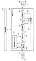
図21は、第2の実施形態に従う画像符号化装置を示しており、図1に示した第1の実施形態に従う画像符号化装置における量子化マトリクス変調部110が演算精度制御パラメータ変調部140に置き換えられている。
FIG. 21 shows an image encoding device according to the second embodiment, and the quantization
演算精度制御パラメータ変調部140には、符号化制御部113から式(28)中のLSまたは式(29)中のILSに相当する演算精度制御パラメータ141が与えられ、またモード判定部103から式(26)〜(29)中のidxに相当する、変調方法を示す変調インデックス142が与えられる。演算精度制御パラメータ変調部140では、変調インデックス142により示される変調方法に従って演算精度制御パラメータ141に対して変調が施され、式(28)のMLSまたは式(29)のMILSに相当する、変調された演算精度制御パラメータ(変調制御パラメータという)143が生成される。
The calculation accuracy control
変調制御パラメータ143は、量子化器105及び逆量子化器106に与えられる。量子化器105及び逆量子化器106では、変調制御パラメータ143に従って変換係数123の量子化及び量子化変換係数124の逆量子化が行われる。
The modulation control parameter 143 is given to the
このように第2の実施形態によれば、第1の実施形態における量子化マトリクスの変調と同等の処理である、量子化/逆量子化時の演算精度を制御する演算精度制御パラメータの変調を行うことによって、第1の実施形態と同様の効果を得ることができる。 As described above, according to the second embodiment, the modulation of the calculation accuracy control parameter for controlling the calculation accuracy at the time of quantization / inverse quantization, which is the same processing as the modulation of the quantization matrix in the first embodiment, is performed. By doing so, the same effect as the first embodiment can be obtained.
(第3の実施形態)
量子化器105及び逆量子化器106が式(4)及び式(16)に対応する量子化/逆量子化を行う場合、第1の実施形態のように量子化マトリクスに対して変調を行う代わりに、量子化パラメータに変調を行ってもよい。この場合、式(4)及び式(16)はそれぞれ次のように変更される。
When the
ここで、QPstepは変調量子化パラメータであり、次式で表わされる。
Here, QP step is a modulation quantization parameter and is expressed by the following equation.
ここで、Qstepは量子化パラメータである。
Here, Q step is a quantization parameter.
このように量子化パラメータQstepに対して変調を行うことは、量子化マトリクスに対して変調を行うことと同義である。式(5)と式(17)、式(6)と式(18)のような量子化/逆量子化に対しても、演算精度制御パラメータを調整することにより量子化パラメータに対する変調を行うことが可能である。Modulating the quantization parameter Q step in this way is synonymous with performing modulation on the quantization matrix. Also for quantization / inverse quantization such as Expression (5) and Expression (17), Expression (6), and Expression (18), modulation on the quantization parameter is performed by adjusting the calculation accuracy control parameter. Is possible.
図22は、第3の実施形態に従う画像符号化装置を示しており、図1に示した第1の実施形態に従う画像符号化装置における量子化マトリクス変調部110が量子化パラメータ変調部150に置き換えられている。
FIG. 22 shows an image encoding device according to the third embodiment, and the quantization
量子化パラメータ変調部150には、符号化制御部113から式(32)中のQstepに相当する量子化パラメータ151が与えられ、またモード判定部103から式(30)〜(31)中のidxに相当する、変調方法を示す変調インデックス152が与えられる。量子化パラメータ変調部150では、変調インデックス152により示される変調方法に従って量子化パラメータ151に対して変調が施され、式(30)〜(32)のQPstepに相当する変調量子化パラメータ(変調量子化パラメータという)153が生成される。The quantization
変調量子化パラメータ153は、量子化器105及び逆量子化器106に与えられる。量子化器105及び逆量子化器106では、変調量子化パラメータ153に従って変換係数123の量子化及び量子化変換係数124の逆量子化が行われる。
The
このように第3の実施形態によれば、第1の実施形態における量子化マトリクスの変調と同等の処理である、量子化/逆量子化時の量子化パラメータの変調を行うことによって、第1の実施形態と同様の効果を得ることができる。 As described above, according to the third embodiment, the first process is performed by modulating the quantization parameter at the time of quantization / inverse quantization, which is the same process as the modulation of the quantization matrix in the first embodiment. The same effect as that of the embodiment can be obtained.
(第4の実施形態)
図23は、本発明の第4の実施形態に従う画像符号化装置を示しており、図1に示した第1の実施形態に従う画像符号化装置における量子化マトリクス変調部110が量子スケールテーブル変調部160に置き換えられている。(Fourth embodiment)
FIG. 23 shows an image encoding device according to the fourth embodiment of the present invention, and the quantization
量子スケールテーブル変調部160には、符号化制御部113から後述する量子スケールテーブル161が与えられ、またモード判定部103から変調方法を示す変調インデックス162が与えられる。量子スケールテーブル変調部160では、変調インデックス162により示される変調方法に従って量子スケールテーブル161に対して変調が施され、変調量子スケールテーブル163が生成される。
The quantum scale
変調量子スケールテーブル163は、量子化器105及び逆量子化器106に与えられる。量子化器105及び逆量子化器106では、変調量子スケールテーブル163に従って変換係数123の量子化及び量子化変換係数124の逆量子化が行われる。
The modulation quantum scale table 163 is provided to the
具体的に説明すると、量子スケールテーブル変調部160は量子化の粗さを決定する量子化パラメータによって制御される量子化スケールの変更幅を設定する機能を有する。このとき、量子化器105で行われる量子化及び逆量子化器106で行われる逆量子化は、次式で表される。
![]()
![]()
ここでQTstepは量子化スケールを示しており、この値の大きさによって量子化の粗さが制御される。一方、qpは量子化パラメータを示しており、qpによって定められた量子化スケールが導出される。Tidxは量子スケールテーブルに対する変調インデックス162を示している。ここで、qpを変更すると量子化スケールが変化し、量子化の粗さも変化する。
Here, QT step indicates a quantization scale, and the roughness of quantization is controlled by the magnitude of this value. On the other hand, qp indicates a quantization parameter, and a quantization scale determined by qp is derived. Tidx indicates a
H. 264のような従来の動画像符号化方式では、量子化パラメータの値に応じて固定の量子化スケールが導出される。本実施形態では変調インデックス162によって、量子化パラメータを変更したときの量子化スケールの幅を変更することが可能である。
In a conventional moving picture coding scheme such as H.264, a fixed quantization scale is derived according to the value of a quantization parameter. In this embodiment, the width of the quantization scale when the quantization parameter is changed can be changed by the
図24は、量子化パラメータと量子化スケールの関係を示している。本実施形態では、このように量子化パラメータと量子化スケールとを対応付けたテーブルを量子スケールテーブルと呼ぶ。図24中に示されるサークルは、量子化パラメータqp(QP±i;i=1,2,・・・)を示している。すなわち、QPは基準の量子化パラメータ(基準パラメータという)であり、量子化パラメータqpはQPからの変化を示している。一方、サークル間の距離が量子化スケールΔを示している。 FIG. 24 shows the relationship between the quantization parameter and the quantization scale. In the present embodiment, a table in which the quantization parameter and the quantization scale are associated with each other is referred to as a quantum scale table. Circles shown in FIG. 24 indicate quantization parameters qp (QP ± i; i = 1, 2,...). That is, QP is a reference quantization parameter (referred to as a reference parameter), and the quantization parameter qp indicates a change from QP. On the other hand, the distance between the circles indicates the quantization scale Δ.
図24(a)は、変調インデックス162がTidx=0の時に対応する、量子化スケールの精度を変更しない場合(量子スケールテーブルの変調を行わない場合)の量子スケールテーブルの例を示している。図24(a)によると、量子化パラメータqpを基準パラメータQPから変更した場合、量子化スケールΔが量子化パラメータに応じて線形に変化している。このような量子化パラメータの変更は、周知のように例えば出力バッファ112のバッファ量に応じて行われる。
FIG. 24A shows an example of the quantum scale table corresponding to the case where the
一方、図24(b)は変調インデックス162がTidx=1の場合の例であり、この例ではqpが±1までに増減したときの量子化スケールΔが約2倍に拡大されている。また、図24(c)は変調インデックス162がTidx=2の場合の例であり、この例ではqpが±1までに増減したときの量子化スケールΔが半分に削減されている。さらに、図24(d)は変調インデックス162がTidx=3の場合の例であり、この例ではqpが±2までに増減したときの量子化スケールが半分に削減されている。ここで、量子スケールテーブルを変調するとは、図24(a)に示した基準の量子スケールテーブルを図24(b)(c)及び(d)のように変調インデックス162に従って変化させることを意味している。この場合、例えば図24(a)は量子スケールテーブル変調部160に入力される量子スケールテーブル161に相当し、図24(b)(c)及び(d)が変調量子スケールテーブル163に相当する。
On the other hand, FIG. 24B shows an example in which the
表4には、変調インデックス162:Tidxに対応する量子化パラメータの変動値と、そのときの量子化スケールの変動値が示されている。表4に従って、与えられたqpから対象ブロックに対応する量子化スケールの変更幅が決定され、QTstepが設定される。このテーブル情報を精度変調情報603と呼ぶ。このように、変調インデックス162を変更することによって、マクロブロック単位で量子化スケールの精度を変更することが可能となる。
次に、本実施形態におけるシンタクスについて説明する。シンタクス構造は、第1の実施形態で説明した図13と同一であるため説明を省略する。
図25のシーケンスパラメータセットシンタクス内に示されるseq_moduletaed_quantization_precision_flagは、量子化精度の変調の利用可否をシーケンス毎に変更するかどうかを示すフラグである。当該フラグseq_moduletaed_quantization_precision_flagがTRUEであるときは、量子化パラメータに対応する量子化スケールの精度変調を行うかどうかをシーケンス単位で切り替えることが可能である。一方、当該フラグseq_moduletaed_quantization_precision_flagがFALSEであるときは、シーケンス内では量子化パラメータに対応する量子化スケールの精度変調を用いることができない。
Next, the syntax in this embodiment is demonstrated. Since the syntax structure is the same as that of FIG. 13 described in the first embodiment, the description thereof is omitted.
The seq_moduletaed_quantization_precision_flag shown in the sequence parameter set syntax of FIG. 25 is a flag indicating whether or not the use of quantization precision modulation is changed for each sequence. When the flag seq_moduletaed_quantization_precision_flag is TRUE, it is possible to switch whether to perform quantization scale precision modulation corresponding to the quantization parameter in sequence units. On the other hand, when the flag seq_moduletaed_quantization_precision_flag is FALSE, the precision modulation of the quantization scale corresponding to the quantization parameter cannot be used in the sequence.
図26のピクチャパラメータセットシンタクス内に示されるpic_moduletaed_quantization_precision_flagは、量子化精度の変調の利用可否をピクチャ毎に変更するかどうかを示すフラグである。当該フラグpic_moduletaed_quantization_precision_flagがTRUEであるときは、量子化パラメータに対応する量子化スケールの精度変調を利用するかどうかをピクチャ単位で切り替えることが可能である。一方、当該フラグpic_moduletaed_quantization_precision_flagがFALSEであるときは、ピクチャ内では量子化パラメータに対応する量子化スケールの精度変調を用いることができない。 The pic_moduletaed_quantization_precision_flag shown in the picture parameter set syntax of FIG. 26 is a flag indicating whether or not the use of quantization precision modulation is changed for each picture. When the flag pic_moduletaed_quantization_precision_flag is TRUE, it is possible to switch on a picture-by-picture basis whether or not to use quantization scale precision modulation corresponding to the quantization parameter. On the other hand, when the flag pic_moduletaed_quantization_precision_flag is FALSE, the precision modulation of the quantization scale corresponding to the quantization parameter cannot be used in the picture.
図27のスライスヘッダシンタクス内に示されるslice_moduletaed_quantization_precision_flagは、量子化精度の変調の利用可否をスライス毎に変更するかどうかを示すフラグである。当該フラグslice_moduletaed_quantization_precision_flagがTRUEであるときは、量子化パラメータに対応する量子化スケールの精度変調を利用するかどうかをスライス単位で切り替えることが可能である。一方、当該フラグslice_moduletaed_quantization_precision_flagがFALSEであるときは、スライス内では量子化パラメータに対応する量子化スケールの精度変調を用いることができない。 The slice_moduletaed_quantization_precision_flag shown in the slice header syntax of FIG. 27 is a flag indicating whether or not the use of quantization precision modulation is changed for each slice. When the flag slice_moduletaed_quantization_precision_flag is TRUE, it is possible to switch in units of slices whether to use the quantization scale precision modulation corresponding to the quantization parameter. On the other hand, when the flag slice_moduletaed_quantization_precision_flag is FALSE, the precision modulation of the quantization scale corresponding to the quantization parameter cannot be used in the slice.
図28のマクロブロックレイヤーシンタクス内に示されるprecision_modulation_indexは精度変調インデックスを表す。coded_block_patternは当該ブロックに変換係数が発生しているかを示すインデックスである。当該インデックスcoded_block_patternが0である場合、当該マクロブロック内では変換係数が発生しないため、復号化の際に逆量子化を行う必要が無い。このような場合は、量子化処理に関する情報を送る必要性がないため、precision_modulation_indexは送信されない。 The precision_modulation_index shown in the macroblock layer syntax of FIG. 28 represents a precision modulation index. coded_block_pattern is an index indicating whether a conversion coefficient is generated in the block. When the index coded_block_pattern is 0, no transform coefficient is generated in the macroblock, so that it is not necessary to perform inverse quantization at the time of decoding. In such a case, precision_modulation_index is not transmitted because there is no need to send information related to the quantization process.
一方、modeは予測モードを示すインデックスである。当該インデックスmodeがskipモードを選択している場合、当該ブロックは同様に変換係数を送信しない。よってprecision_modulation_indexは送信されない。 On the other hand, mode is an index indicating the prediction mode. When the index mode selects the skip mode, the block does not transmit the transform coefficient in the same manner. Therefore, precision_modulation_index is not transmitted.
図28中に示されるmb_qp_deltaは、量子化パラメータの変動値を示している。H. 264のような従来の動画像符号化方式では、当該マクロブロックの1つ前に符号化されたマクロブロック(前マクロブロックと呼ぶ)の量子化パラメータと当該マクロブロックの量子化パラメータの差分値を符号化するシンタクスとなっている。mb_qp_deltaは、この差分値を表している。量子化パラメータが変化しない場合、当該マクロブロックの量子化精度は変更されないため、mb_qp_delta=0のときはprecision_modulation_indexは送信されない。 Mb_qp_delta shown in FIG. 28 indicates the variation value of the quantization parameter. In a conventional moving picture coding method such as H.264, the difference between the quantization parameter of a macroblock (referred to as the previous macroblock) coded immediately before the macroblock and the quantization parameter of the macroblock The syntax is to encode the value. mb_qp_delta represents this difference value. When the quantization parameter does not change, the quantization accuracy of the macroblock is not changed, and therefore precision_modulation_index is not transmitted when mb_qp_delta = 0.
CurrentModulatedQuantizationPrecisionFlagは、seq_moduletaed_quantization_precision_flag, pic_moduletaed_quantization_precision_flag及びslice_moduletaed_quantization_precision_flagの少なくとも1つのフラグがTRUEであるときにTRUEとなり、この条件が満たされない場合はFALSEを取る。当該フラグCurrentModulatedQuantizationPrecisionFlagがFALSEであるとき、precision_modulation_indexは送信されず、内部の変調インデックスはTidx=0が設定される。precision_modulation_indexは、表4に示されるようにインデックス毎に量子化パラメータ変動値と量子化スケール変動値が決められたテーブルを予め持っている。 CurrentModulatedQuantizationPrecisionFlag becomes TRUE when at least one flag of seq_moduletaed_quantization_precision_flag, pic_moduletaed_quantization_precision_flag, and slice_moduletaed_quantization_precision_flag is TRUE, and takes FALSE when this condition is not satisfied. When the flag CurrentModulatedQuantizationPrecisionFlag is FALSE, precision_modulation_index is not transmitted and the internal modulation index is set to Tidx = 0. As shown in Table 4, precision_modulation_index has a table in which a quantization parameter variation value and a quantization scale variation value are determined for each index in advance.
図27で示されるスライスヘッダシンタクスを図29で表されるようなシンタクスに変えてもよい。図29のシンタクスによると、量子化精度の変調の利用可否ではなく、スライスレベルで量子化パラメータに対応する量子化スケールの変調インデックスを変えることができる。slice_precision_modulation_indexは、量子化パラメータに対応する量子化スケールの変調インデックスを示している。もし、更に細かいマクロブロックレベルで精度を変調したい場合は、図28で示されるマクロブロックヘッダシンタクスで上書きすればよい。 The slice header syntax shown in FIG. 27 may be changed to the syntax shown in FIG. According to the syntax of FIG. 29, it is possible to change the modulation index of the quantization scale corresponding to the quantization parameter at the slice level, rather than whether or not the quantization accuracy modulation can be used. The slice_precision_modulation_index indicates the modulation index of the quantization scale corresponding to the quantization parameter. If it is desired to modulate the accuracy at a finer macroblock level, it may be overwritten with the macroblock header syntax shown in FIG.
ここで、CurrentModulatedQuantizationPrecisionFlagは、スライスヘッダーより上のシンタクスエレメントであるseq_moduletaed_quantization_precision_flag及び pic_moduletaed_quantization_precision_flagの少なくとも1つがTRUEであるときにTRUEとなり、この条件が満たされない場合はFALSEを取る。当該フラグCurrentModulatedQuantizationPrecisionFlagがFALSEを取る場合、slice_precision_modulation_indexは送信されず、内部の変調インデックスはTidx=0が設定される。 Here, CurrentModulatedQuantizationPrecisionFlag becomes TRUE when at least one of seq_moduletaed_quantization_precision_flag and pic_moduletaed_quantization_precision_flag which are syntax elements above the slice header is TRUE, and takes FALSE when this condition is not satisfied. When the flag CurrentModulatedQuantizationPrecisionFlag is FALSE, slice_precision_modulation_index is not transmitted, and Tidx = 0 is set as the internal modulation index.
以上説明したように、第4の実施形態では量子化パラメータに対して量子化精度を変更可能な変調インデックスを用いて、変換係数に適した量子化精度を設定して量子化/逆量子化を行い、量子化変換係数と量子化精度の変調方法を示す変調インデックスをエントロピー符号化する。従って、第1〜第3の実施形態と同様に高い符号化効率を維持しつつ、復号化側の演算コストを増加させない符号化が実現できる。すなわち、対象ブロックの内容等に応じて好適な符号化を行うことができる。 As described above, in the fourth embodiment, the quantization index suitable for the transform coefficient is set using the modulation index that can change the quantization accuracy for the quantization parameter, and quantization / inverse quantization is performed. And entropy-encode the modulation index indicating the quantization transform coefficient and the modulation method of quantization accuracy. Accordingly, it is possible to realize encoding that does not increase the calculation cost on the decoding side while maintaining high encoding efficiency as in the first to third embodiments. That is, suitable encoding can be performed according to the contents of the target block.
なお、第1の実施形態でも述べたように、選択されたモードでの符号化の際、復号画像信号の生成は選択されたモードについてのみ行えばよく、予測モード判定のためのループ内では必ずしも実行しなくてもよい。 Note that, as described in the first embodiment, when encoding in the selected mode, generation of a decoded image signal need only be performed for the selected mode, and is not necessarily performed in the loop for prediction mode determination. It is not necessary to execute.
(第1〜第4の実施形態の変形例)
(1)第1の実施形態においては、符号化ループを対象ブロックの全ての組み合わせに対して繰り返し仮符号化する例を示した。しかし、演算処理を簡単化するために、予め選択されやすい予測モード、変調インデックス及びブロックサイズなどのみについて仮符号化を行い、選択されにくい、対象ブロックの組み合わせの処理を省略してもよい。このような選択的な仮符号化を行うことにより、符号化効率の低下を抑え、また仮符号化に必要となる処理量を抑えることが可能である。(Modification of the first to fourth embodiments)
(1) In the first embodiment, the example in which the encoding loop is repeatedly provisionally encoded with respect to all combinations of the target blocks has been shown. However, in order to simplify the arithmetic processing, provisional encoding may be performed only for a prediction mode, a modulation index, a block size, and the like that are easily selected in advance, and processing for combining target blocks that are difficult to select may be omitted. By performing such selective provisional encoding, it is possible to suppress a decrease in encoding efficiency and to suppress a processing amount necessary for provisional encoding.
(2)第1の実施形態においては、表1〜表3に示されるような変調モデルと変調制御パラメータの組み合わせテーブルによって、変調マトリクスが生成される例を示した。しかし、表1及び表2のように予め利用する変調マトリクスが固定されている場合は、予め内部メモリに変調マトリクスを保持していてもよい。この場合、マクロブロック毎に変調マトリクスを生成する処理が省略できるため、演算コストを削減することができる。 (2) In the first embodiment, an example in which a modulation matrix is generated by a combination table of modulation models and modulation control parameters as shown in Tables 1 to 3 has been described. However, when the modulation matrix to be used in advance is fixed as shown in Tables 1 and 2, the modulation matrix may be held in the internal memory in advance. In this case, since the process of generating a modulation matrix for each macroblock can be omitted, the calculation cost can be reduced.
(3)第1の実施形態においては、量子化マトリクスを変調するために量子化マトリクスと変調マトリクスを加算する場合について説明し。一方、量子化マトリクスと変調マトリクスとの間で減算、乗算、除算またはビットシフトを用いて量子化マトリクスに変調を施してよい。また、これらの演算を組み合わせて量子化マトリクスの変調を行ってもよい。 (3) In the first embodiment, a case where the quantization matrix and the modulation matrix are added to modulate the quantization matrix will be described. On the other hand, the quantization matrix may be modulated using subtraction, multiplication, division, or bit shift between the quantization matrix and the modulation matrix. Further, the quantization matrix may be modulated by combining these operations.
同様に、第2の実施形態において演算精度制御パラメータと変調マトリクスとの間で、加算のみでなく減算、乗算、除算またはビットシフトを用いて演算精度制御パラメータに変調を施してもよい。 Similarly, in the second embodiment, modulation may be performed on the calculation accuracy control parameter using not only addition but also subtraction, multiplication, division, or bit shift between the calculation accuracy control parameter and the modulation matrix.
同様に、第3の実施形態において量子化パラメータと変調マトリクスとの間で、加算のみでなく減算、乗算、除算またはビットシフトを用いて量子化パラメータに変調を施してもよい。 Similarly, in the third embodiment, the quantization parameter may be modulated using subtraction, multiplication, division, or bit shift as well as addition between the quantization parameter and the modulation matrix.
(4)第1の実施形態においては、変調マトリクスを生成するために市街地距離による生成モデルを用いている。周波数成分の距離を表すパラメータrとしては、市街地距離だけでなく、市街地距離、ユークリッド距離等を含むミンコフスキー距離の中から少なくとも1つを用いればよい。 (4) In the first embodiment, a generation model based on city distance is used to generate a modulation matrix. As the parameter r representing the frequency component distance, at least one of the Minkowski distances including the city distance, the Euclidean distance, etc. may be used as well as the city distance.
(5)第1〜第4の実施形態においては、処理対象フレームを16×16画素サイズなどの短形ブロックに分割し、図2に示したように画面左上のブロックから右下に向かって順に符号化する場合について説明しているが、符号化順序はこれに限られない。例えば、右下から左上に向かって順に符号化を行ってもよいし、画面中央から渦巻状に向かって順に符号化を行ってもよい。さらに、右上から左下に向かって順に符号化を行ってもよいし、画面の周辺部から中心部に向かって順に符号化を行ってもよい。 (5) In the first to fourth embodiments, the processing target frame is divided into short blocks of 16 × 16 pixel size and the like, and as shown in FIG. Although the case of encoding is described, the encoding order is not limited to this. For example, encoding may be performed sequentially from the lower right to the upper left, or may be performed sequentially from the center of the screen toward the spiral. Furthermore, encoding may be performed in order from the upper right to the lower left, or encoding may be performed in order from the periphery of the screen toward the center.
(6)第1〜第4の実施形態においては、量子化ブロックサイズを4×4画素ブロック、8×8画素ブロックとして説明を行ったが、対象ブロックは均一なブロック形状にする必要なく、16×8画素ブロック、8×16画素ブロック、8×4画素ブロック、4×8画素ブロックなどのブロックサイズであってもよい。また、1つのマクロブロック内でも均一なブロックサイズを取る必要はなく、それぞれ異なるサイズのブロックを混在させてもよい。この場合、分割数が増えると分割情報を符号化するための符号量が増加するが、変換係数の符号量と局部復号画像とのバランスを考慮して、ブロックサイズを選択すればよい。 (6) In the first to fourth embodiments, the quantization block size has been described as a 4 × 4 pixel block and an 8 × 8 pixel block. However, the target block does not need to have a uniform block shape. The block size may be a x8 pixel block, an 8x16 pixel block, an 8x4 pixel block, a 4x8 pixel block, or the like. Also, it is not necessary to have a uniform block size within one macroblock, and blocks of different sizes may be mixed. In this case, the code amount for encoding the division information increases as the number of divisions increases, but the block size may be selected in consideration of the balance between the code amount of the transform coefficient and the locally decoded image.
(7)第1〜第4の実施形態では変換ブロックサイズと量子化ブロックサイズが同じ場合の例を示しているが、ブロックサイズがそれぞれ異なっていても実現は可能である。この場合も上述の通り、符号量と局部復号画像のバランスを考慮してブロックサイズの組み合わせを選択すればよい。 (7) In the first to fourth embodiments, an example in which the transform block size and the quantization block size are the same is shown, but the present invention can be realized even if the block sizes are different. Also in this case, as described above, a combination of block sizes may be selected in consideration of the balance between the code amount and the locally decoded image.
<画像復号化装置>
次に、画像復号化に関する第5〜第8の実施形態について述べる。
(第5の実施形態)
図30は、図1〜図20を用いて説明した第1の実施形態に従う画像符号化装置に対応する、第5の実施形態に従う画像復号化装置を示している。図1に示した画像符号化装置から送出され、蓄積系または伝送系を経て送られてきた符号化ビットストリーム620は入力バッファ601に一度蓄えられる。入力バッファ601から、多重化された符号化データが復号化ユニット600に入力される。<Image decoding device>
Next, fifth to eighth embodiments relating to image decoding will be described.
(Fifth embodiment)
FIG. 30 shows an image decoding device according to the fifth embodiment corresponding to the image encoding device according to the first embodiment described with reference to FIGS. 1 to 20. A
復号化ユニット600では、符号化データがエントロピー復号化器602に入力される。エントロピー復号化器602では、1フレーム毎に第1の実施形態において図13〜図20で説明したシンタクスに基づいて構文解析による解読が行われる。すなわち、エントロピー復号化器602では、図13に示したシンタクス構造に従ってハイレベルシンタクス、スライスレベルシンタクス及びマクロブロックレベルシンタクスのそれぞれに対して、順次各シンタクスの符号列のエントロピー復号化が行われ、量子化変換係数621、量子化マトリクス631、変調インデックス632、量子化パラメータ及び予測モード情報627(動きベクトル情報を含む)などが解読される。
In the
量子化変換係数621は、逆量子化器603に入力される。量子化マトリクス631及び変調インデックス632は、量子化マトリクス変調部610に入力される。量子化マトリクス変調部610では、変調インデックス632で示される変調方法を用いて量子化マトリクス632が変調され、変調量子化マトリクス633が生成される。変調量子化マトリクス633は、逆量子化器603に与えられる。
The quantized
逆量子化器603では、量子化変換係数621に対して変調量子化マトリクス633に基づいて逆量子化が施される。ここで必要な量子化に関するパラメータ(例えば量子化パラメータなど)は、エントロピー復号化器602から復号化制御部609へ設定されており、逆量子化の際に読み込まれる。
In the
逆量子化後の変換係数622は、逆変換器604に入力される。逆変換器604では、逆量子化後の変換係数622に対して図1の画像符号化装置における変換器104での変換と逆の変換、例えばIDCTのような逆直交変換が行われ、復号予測残差信号623が生成される。ここでは、逆直交変換の例について説明したが、図1に示した画像符号化装置内の変換器104でウェーブレット変換や独立成分分析などが行われている場合、逆変換器604では逆ウェーブレット変換や逆独立成分分析などが行われる。
The
復号予測残差信号623は、加算器605によって予測器607からの予測画像信号624と加算され、復号画像信号625が生成される。復号画像信号625は参照メモリ606に蓄積されると共に、参照メモリ606から読み出され、復号化ユニット600から出力される。復号化ユニット600から出力される復号画像信号は、出力バッファ608に一旦蓄積された後、復号化制御部609が管理する出力タイミングに従って再生画像信号628として出力される。
The decoded prediction
エントロピー復号化器602によって解読された予測モード情報627は、予測器607へ入力される。一方、既に復号化が終了した復号画像信号が蓄積された参照メモリ606から読み出される参照画像信号626も、予測器607へ入力される。予測器607では、予測モード情報627(動きベクトル情報を含む)を基にフレーム間予測またはフレーム内予測が行われることにより、予測画像信号624が生成される。予測画像信号は642加算器605へ入力される。
The
復号化制御部609は、入力バッファ601及び出力バッファ608に対する出力タイミングの制御、復号化タイミングの制御及び参照メモリ606の管理を含む復号化の処理全般の制御を行う。
The
復号化ユニット600及び復号化制御部609の処理は、ハードウェアにより実現することも可能であるが、コンピュータを用いてソフトウェア(プログラム)によって実現することも可能である。
The processing of the
本実施形態における逆量子化器603の処理は、図1の画像符号化装置における逆量子化器106の処理と同様である。すなわち、逆量子化器603では、エントロピー復号化器602によって解読された変換係数713に対して、変調量子化マトリクス118と量子化パラメータを用いて逆量子化が行われる。ここで、逆量子化の一例は式(15)に示された通りである。一方、変換係数の符号を考慮した式(16)のような逆量子化も可能である。演算を簡単化するため、Qstepを2のべき乗で設計した式(17)のような逆量子化も可能である。演算精度を抑えるために周波数成分毎に演算精度を変更する場合、式(18)に示されるような逆量子化を行うことも可能である。The processing of the
一方、量子化マトリクス変調部610は図1の画像符号化装置における量子化マトリクス変調部110と同様に、例えば図6に示したように変調マトリクス設定部201と変調量子化マトリクス生成部202により実現される。変調マトリクス設定部201は例えば図7に示したように切替器301と変調マトリクス生成部302,303及び304を含む。変調量子化マトリクス生成部202は、例えば図10に示すように算術演算器を用いて実現される。量子化マトリクス変調部610の動作は、図1の画像符号化装置における量子化マトリクス変調部110の動作と全く同様である。
On the other hand, the quantization
(第6の実施形態)
逆量子化器603が式(18)に対応する逆量子化を行う場合、第5の実施形態のように量子化マトリクスに対して変調を行う代わりに、逆量子化時の演算精度を制御する演算精度制御パラメータに対して変調を行ってもよい。この場合、式(18)は式(27)のように変更され、また式(27)中のIMLSは式(29)で表される。(Sixth embodiment)
When the
図31は、図21に示した第2の実施形態に従う画像符号化装置に対応する、第6の実施形態に従う画像復号化装置を示している。図31の画像復号化装置では、図30に示した第5の実施形態に従う画像復号化装置における量子化マトリクス変調部610が演算精度制御パラメータ変調部640に置き換えられている。
FIG. 31 shows an image decoding apparatus according to the sixth embodiment corresponding to the image encoding apparatus according to the second embodiment shown in FIG. In the image decoding device in FIG. 31, the quantization
演算精度制御パラメータ変調部640には、復号化制御部609から式(29)中のILSに相当する演算精度制御パラメータ641が与えられ、またエントロピー復号化器602から式(27)(29)中のidxに相当するインデックス(変調方法を示すインデックス)642が与えられる。演算精度制御パラメータ変調部640では、インデックス642により示される変調方法に従って演算精度制御パラメータ641に対して変調が施される。これにより演算精度制御パラメータ変調部640では、式(29)のMILSに相当する、変調された演算精度制御パラメータ(変調制御パラメータという)643が生成される。変調制御パラメータ643は、逆量子化器603に与えられる。逆量子化器603では、変調制御パラメータ643に従って量子化変換係数621の逆量子化が行われる。
The calculation accuracy
(第7の実施形態)
逆量子化器603が式(16)に対応する逆量子化を行う場合、第5の実施形態のように量子化マトリクスに対して変調を行う代わりに、量子化パラメータに変調を行ってもよい。この場合、式(16)は式(31)のように変更され、また式(31)中の変調量子化パラメータQPstepは式(32)で表される。(Seventh embodiment)
When the
図32は、図22に示した第3の実施形態に従う画像符号化装置に対応する、第7の実施形態に従う画像復号化装置を示している。図32の画像復号化装置では、図30に示した第5の実施形態に従う画像復号化装置における量子化マトリクス変調部610が量子化パラメータ変調部650に置き換えられている。
FIG. 32 shows an image decoding apparatus according to the seventh embodiment corresponding to the image encoding apparatus according to the third embodiment shown in FIG. In the image decoding device in FIG. 32, the quantization
量子化パラメータ変調部650には、復号化制御部609から式(32)中のQstepに相当する量子化パラメータ651が与えられ、またエントロピー復号化器602から式(31)(32)中のidxに相当するインデックス(変調方法を示すインデックス)652が与えられる。量子化パラメータ変調部650では、インデックス652により示される変調方法に従って量子化パラメータ651に対して変調が施され、式(31)のQPstepに相当する、変調量子化パラメータ653が生成される。変調量子化パラメータ653は、逆量子化器603に与えられる。逆量子化器603では、変量子化パラメータ653に従って量子化変換係数621の逆量子化が行われる。The quantization
(第8の実施形態)
図33は、図23に示した第4の実施形態に従う画像符号化装置に対応する、第8の実施形態に従う画像復号化装置を示している。図33の画像復号化装置では、図30に示した第5の実施形態に従う画像復号化装置における量子化マトリクス変調部610が量子スケールテーブル変調部660に置き換えられている。(Eighth embodiment)
FIG. 33 shows an image decoding apparatus according to the eighth embodiment corresponding to the image encoding apparatus according to the fourth embodiment shown in FIG. In the image decoding device in FIG. 33, the quantization
量子スケールテーブル変調部660には、エントロピー復号化器602によって解読された量子スケールテーブル661及び変調方法を示すインデックス662が与えられる。量子スケールテーブル変調部660では、インデックス662により示される変調方法に従って量子スケールテーブル661に対して変調が施され、変調量子スケールテーブル663が生成される。変調量子スケールテーブル663は、逆量子化器603に与えられる。逆量子化器603では、変調量子スケールテーブル663に従って量子化変換係数621の逆量子化が行われる。
The quantum scale
量子スケールテーブル変調部660は、第4の実施形態における量子化スケールテーブル変調部160と全く同様であるため、説明を省略する。また、本実施形態における符号化データのシンタクス構造は、図13及図25〜図29で説明した通りであるため、説明を省略する。
The quantum scale
上述した各実施形態に従う画像符号化装置及び画像復号化装置は、例えば汎用のコンピュータ装置を基本ハードウェアとして用いることでも実現することが可能である。この場合、上記のプログラムをコンピュータ装置にあらかじめインストールするか、CD−ROMなどの記憶媒体に記憶して、あるいはネットワークを介して上記のプログラムを配布して、このプログラムをコンピュータ装置に適宜インストールすることで実現してもよい。 The image encoding device and the image decoding device according to each of the above-described embodiments can be realized by using, for example, a general-purpose computer device as basic hardware. In this case, the above program is installed in the computer device in advance, or is stored in a storage medium such as a CD-ROM, or the above program is distributed via a network, and this program is installed in the computer device as appropriate. It may be realized with.
なお、本発明は上記実施形態そのままに限定されるものではなく、実施段階ではその要旨を逸脱しない範囲で構成要素を変形して具体化できる。また、上記実施形態に開示されている複数の構成要素の適宜な組み合わせにより、種々の発明を形成できる。例えば、実施形態に示される全構成要素から幾つかの構成要素を削除してもよい。さらに、異なる実施形態にわたる構成要素を適宜組み合わせてもよい。 Note that the present invention is not limited to the above-described embodiment as it is, and can be embodied by modifying the constituent elements without departing from the scope of the invention in the implementation stage. In addition, various inventions can be formed by appropriately combining a plurality of constituent elements disclosed in the embodiment. For example, some components may be deleted from all the components shown in the embodiment. Furthermore, constituent elements over different embodiments may be appropriately combined.
本発明は、動画像や静止画像の高能率圧縮符号化/復号技術に利用することが可能である。 The present invention can be used for high-efficiency compression encoding / decoding technology for moving images and still images.
Claims (22)
前記入力画像信号と前記予測画像信号との差をとって予測残差信号を生成することと;
前記予測残差信号を変換して変換係数を生成することと;
(a)量子化マトリクス、(b)量子化のための演算精度を制御する制御パラメータ、(c)量子化の粗さを表す量子化パラメータ、及び(d)量子化の粗さを表す量子化パラメータに量子化スケールを対応付けたテーブル、のいずれか一つに対して変調を行い、量子化に関する変調結果を得ることと;
前記変調結果を用いて前記変換係数を量子化して量子化変換係数を生成することと;
前記量子化変換係数と前記変調に関するインデックスを符号化して符号化データを生成することと;を具備する画像符号化方法。Performing prediction on the input image signal to generate a predicted image signal;
Taking a difference between the input image signal and the predicted image signal to generate a predicted residual signal;
Transforming the prediction residual signal to generate transform coefficients;
(A) a quantization matrix, (b) a control parameter that controls the calculation accuracy for quantization, (c) a quantization parameter that represents the roughness of quantization, and (d) a quantization that represents the roughness of quantization. Performing modulation on any one of the tables in which the quantization scale is associated with the parameter to obtain a modulation result relating to quantization;
Quantizing the transform coefficient using the modulation result to generate a quantized transform coefficient;
Encoding the quantized transform coefficient and the index related to the modulation to generate encoded data.
前記入力画像信号と前記予測画像信号との差をとって予測残差信号を生成する減算器と;
前記予測残差信号を変換して変換係数を生成する変換器と;
(a)量子化マトリクス、(b)量子化のための演算精度を制御する制御パラメータ、(c)量子化の粗さを表す量子化パラメータ、及び(d)量子化の粗さを表す量子化パラメータに量子化スケールを対応付けたテーブル、のいずれか一つに対して変調を行い、量子化に関する変調結果を得る変調部と;
前記変調結果を用いて前記変換係数を量子化して量子化変換係数を生成する量子化器と;
前記量子化変換係数と、前記変調に関するインデックスとを符号化して符号化データを生成する符号化器と;を具備する画像符号化装置。A predictor that performs prediction on the input image signal to generate a predicted image signal;
A subtractor that takes a difference between the input image signal and the predicted image signal to generate a predicted residual signal;
A converter for converting the prediction residual signal to generate a conversion coefficient;
(A) a quantization matrix, (b) a control parameter that controls the calculation accuracy for quantization, (c) a quantization parameter that represents the roughness of quantization, and (d) a quantization that represents the roughness of quantization. A modulation unit that modulates any one of the tables in which the quantization scale is associated with the parameter, and obtains a modulation result related to quantization;
A quantizer that quantizes the transform coefficient using the modulation result to generate a quantized transform coefficient;
An image encoding device comprising: an encoder that encodes the quantized transform coefficient and an index related to the modulation to generate encoded data.
前記インデックスに従って(a)量子化マトリクス、(b)量子化のための演算精度を制御する制御パラメータ、(c)量子化の粗さを表す量子化パラメータ、及び(d)量子化の粗さを表す量子化パラメータに量子化スケールを対応付けたテーブル、のいずれか一つに対して変調を行い、量子化に関する変調結果を得ることと;
前記変調結果を用いて前記量子化変換係数を逆量子化して逆量子化変換係数を生成することと;
前記逆量子化変換係数に逆変換を行って予測残差信号を生成することと;
復号画像信号を用いて予測を行って予測画像信号を生成することと;
前記予測画像信号と前記予測残差信号とを加算することによって復号画像信号を生成することと;を具備する画像復号化方法。Decoding encoded data including quantized transform coefficients and an index relating to modulation;
According to the index, (a) a quantization matrix, (b) a control parameter for controlling the calculation accuracy for quantization, (c) a quantization parameter representing the roughness of quantization, and (d) a roughness of quantization Performing modulation on any one of the tables in which a quantization parameter is associated with a quantization scale to obtain a modulation result related to quantization;
Dequantizing the quantized transform coefficient using the modulation result to generate an inverse quantized transform coefficient;
Performing an inverse transform on the inverse quantized transform coefficients to generate a prediction residual signal;
Performing prediction using the decoded image signal to generate a predicted image signal;
An image decoding method comprising: generating a decoded image signal by adding the predicted image signal and the predicted residual signal.
前記変換に関する情報に従って(a)量子化マトリクス、(b)量子化のための演算精度を制御する制御パラメータ、(c)量子化の粗さを表す量子化パラメータ、及び(d)量子化の粗さを表す量子化パラメータに量子化スケールを対応付けたテーブル、のいずれか一つに対して変調を行い、量子化に関する変調結果を得る変調部;
前記変調結果を用いて前記量子化変換係数を逆量子化して逆量子化変換係数を生成する逆量子化器と;
前記逆量子化変換係数に逆変換を行って予測残差信号を生成する逆変換器と;
復号画像信号を用いて予測を行って予測画像信号を生成する予測器と;
前記予測画像信号と前記予測残差信号とを加算することによって復号画像信号を生成する加算器と;を具備する画像復号化装置。A decoder for decoding encoded data including quantized transform coefficients and an index relating to modulation;
(A) a quantization matrix, (b) a control parameter for controlling the calculation accuracy for the quantization, (c) a quantization parameter representing the roughness of the quantization, and (d) a quantization coarse according to the information relating to the transformation. A modulation unit that performs modulation on any one of the tables in which the quantization scales are associated with the quantization scales to obtain a modulation result related to quantization;
An inverse quantizer for inversely quantizing the quantized transform coefficient using the modulation result to generate an inverse quantized transform coefficient;
An inverse transformer that performs an inverse transform on the inverse quantized transform coefficients to generate a prediction residual signal;
A predictor that performs prediction using the decoded image signal to generate a predicted image signal;
An image decoding apparatus comprising: an adder that generates a decoded image signal by adding the prediction image signal and the prediction residual signal.
前記入力画像信号と前記予測画像信号との差をとって予測残差信号を生成することと;
前記予測残差信号を変換して変換係数を生成することと;
(a)量子化マトリクス、(b)量子化のための演算精度を制御する制御パラメータ、(c)量子化の粗さを表す量子化パラメータ、及び(d)量子化の粗さを表す量子化パラメータに量子化スケールを対応付けたテーブル、のいずれか一つに対して変調を行い、量子化に関する変調結果を得ることと;
前記変調結果を用いて前記変換係数を量子化して量子化変換係数を生成することと;
前記量子化変換係数と前記変調に関するインデックスを符号化して符号化データを生成することと;を具備するステップの動作をもたらすコンピュータプログラムの命令を記憶するコンピュータの読み取り可能な記憶媒体。Performing prediction on the input image signal to generate a predicted image signal, executed by a computer;
Taking a difference between the input image signal and the predicted image signal to generate a predicted residual signal;
Transforming the prediction residual signal to generate transform coefficients;
(A) a quantization matrix, (b) a control parameter that controls the calculation accuracy for quantization, (c) a quantization parameter that represents the roughness of quantization, and (d) a quantization that represents the roughness of quantization. Performing modulation on any one of the tables in which the quantization scale is associated with the parameter to obtain a modulation result relating to quantization;
Quantizing the transform coefficient using the modulation result to generate a quantized transform coefficient;
Encoding the quantized transform coefficient and the modulation index to generate encoded data.
量子化変換係数と変調に関するインデックスを含む符号化データを復号することと;
前記変換に関する情報に従って(a)量子化マトリクス、(b)量子化のための演算精度を制御する制御パラメータ、(c)量子化の粗さを表す量子化パラメータ、及び(d)量子化の粗さを表す量子化パラメータに量子化スケールを対応付けたテーブル、のいずれか一つに対して変調を行い、量子化に関する変調結果を得ることと;
前記変調結果を用いて前記量子化変換係数を逆量子化して逆量子化変換係数を生成することと;
前記逆量子化変換係数に逆変換を行って予測残差信号を生成することと;
復号画像信号を用いて予測を行って予測画像信号を生成することと;
前記予測画像信号と前記予測残差信号とを加算することによって復号画像信号を生成することと;を具備するステップの動作をもたらすコンピュータプログラムの命令を記憶するコンピュータの読み取り可能な記憶媒体。Executed by computer,
Decoding encoded data including quantized transform coefficients and an index relating to modulation;
(A) a quantization matrix, (b) a control parameter for controlling the calculation accuracy for the quantization, (c) a quantization parameter representing the roughness of the quantization, and (d) a quantization coarse according to the information relating to the transformation. Performing modulation on any one of the tables in which the quantization scale indicating the quantization is associated with the quantization scale, and obtaining a modulation result related to the quantization;
Dequantizing the quantized transform coefficient using the modulation result to generate an inverse quantized transform coefficient;
Performing an inverse transform on the inverse quantized transform coefficients to generate a prediction residual signal;
Performing prediction using the decoded image signal to generate a predicted image signal;
Generating a decoded image signal by adding the prediction image signal and the prediction residual signal;
Applications Claiming Priority (3)
| Application Number | Priority Date | Filing Date | Title |
|---|---|---|---|
| JP2007106899 | 2007-04-16 | ||
| JP2007106899 | 2007-04-16 | ||
| PCT/JP2008/055012 WO2008132890A1 (en) | 2007-04-16 | 2008-03-18 | Image encoding and image decoding method and device |
Publications (1)
| Publication Number | Publication Date |
|---|---|
| JPWO2008132890A1 true JPWO2008132890A1 (en) | 2010-07-22 |
Family
ID=39925355
Family Applications (1)
| Application Number | Title | Priority Date | Filing Date |
|---|---|---|---|
| JP2009511709A Abandoned JPWO2008132890A1 (en) | 2007-04-16 | 2008-03-18 | Method and apparatus for image encoding and image decoding |
Country Status (13)
| Country | Link |
|---|---|
| US (1) | US20100086028A1 (en) |
| EP (1) | EP2136566A4 (en) |
| JP (1) | JPWO2008132890A1 (en) |
| KR (1) | KR20090115176A (en) |
| CN (1) | CN101622881A (en) |
| AU (1) | AU2008245277A1 (en) |
| BR (1) | BRPI0809255A2 (en) |
| CA (1) | CA2680140A1 (en) |
| MX (1) | MX2009009947A (en) |
| RU (1) | RU2009135396A (en) |
| TW (1) | TW200850013A (en) |
| WO (1) | WO2008132890A1 (en) |
| ZA (1) | ZA200906254B (en) |
Families Citing this family (69)
| Publication number | Priority date | Publication date | Assignee | Title |
|---|---|---|---|---|
| US8045612B1 (en) | 2007-01-19 | 2011-10-25 | Marvell International Ltd. | Fast inverse integer transform for video decoding |
| JPWO2008132890A1 (en) * | 2007-04-16 | 2010-07-22 | 株式会社東芝 | Method and apparatus for image encoding and image decoding |
| US8503527B2 (en) | 2008-10-03 | 2013-08-06 | Qualcomm Incorporated | Video coding with large macroblocks |
| KR101452859B1 (en) * | 2009-08-13 | 2014-10-23 | 삼성전자주식회사 | Method and apparatus for encoding and decoding motion vector |
| CN102045560B (en) | 2009-10-23 | 2013-08-07 | 华为技术有限公司 | Video encoding and decoding method and video encoding and decoding equipment |
| TW201143448A (en) * | 2009-10-30 | 2011-12-01 | Panasonic Corp | Image encoding method, image decoding method, image encoding device and image decoding device |
| JPWO2011052217A1 (en) * | 2009-10-30 | 2013-03-14 | パナソニック株式会社 | Image decoding method, image encoding method, image decoding device, image encoding device, program, and integrated circuit |
| CN102577387B (en) * | 2009-10-30 | 2015-01-14 | 松下电器(美国)知识产权公司 | Decoding method, decoding device, encoding method and encoding device |
| JP5299328B2 (en) * | 2010-03-17 | 2013-09-25 | 富士通株式会社 | Image processing apparatus and image processing method |
| CN102215391B (en) * | 2010-04-09 | 2013-08-28 | 华为技术有限公司 | Video data encoding and decoding method and device as well as transform processing method and device |
| JP5670444B2 (en) | 2010-05-13 | 2015-02-18 | シャープ株式会社 | Encoding device and decoding device |
| CN102281435B (en) * | 2010-06-11 | 2013-10-02 | 华为技术有限公司 | Encoding method, decoding method, encoding device, decoding device and encoding/decoding system |
| WO2012050832A1 (en) | 2010-09-28 | 2012-04-19 | Google Inc. | Systems and methods utilizing efficient video compression techniques for providing static image data |
| WO2012042884A1 (en) | 2010-09-29 | 2012-04-05 | パナソニック株式会社 | Image decoding method, image encoding method, image decoding device, image encoding device, programme, and integrated circuit |
| AU2011310239B2 (en) * | 2010-09-30 | 2015-12-03 | Sun Patent Trust | Image decoding method, image encoding method, image decoding device, image encoding device, programme, and integrated circuit |
| CN102447896B (en) * | 2010-09-30 | 2013-10-09 | 华为技术有限公司 | Method, device and system for processing image residual block |
| US9532059B2 (en) | 2010-10-05 | 2016-12-27 | Google Technology Holdings LLC | Method and apparatus for spatial scalability for video coding |
| JP5741076B2 (en) | 2010-12-09 | 2015-07-01 | ソニー株式会社 | Image processing apparatus and image processing method |
| US20120189052A1 (en) * | 2011-01-24 | 2012-07-26 | Qualcomm Incorporated | Signaling quantization parameter changes for coded units in high efficiency video coding (hevc) |
| US8762797B2 (en) | 2011-04-29 | 2014-06-24 | Google Inc. | Method and apparatus for detecting memory access faults |
| WO2012160890A1 (en) | 2011-05-20 | 2012-11-29 | ソニー株式会社 | Image processing device and image processing method |
| US8989256B2 (en) | 2011-05-25 | 2015-03-24 | Google Inc. | Method and apparatus for using segmentation-based coding of prediction information |
| US9854275B2 (en) * | 2011-06-25 | 2017-12-26 | Qualcomm Incorporated | Quantization in video coding |
| WO2013032794A1 (en) * | 2011-08-23 | 2013-03-07 | Mediatek Singapore Pte. Ltd. | Method and system of transform block processing according to quantization matrix in video coding |
| KR101965388B1 (en) | 2011-11-04 | 2019-04-04 | 주식회사 골드피크이노베이션즈 | Methods of coding quantization parameter and appratuses using the same |
| JP6120490B2 (en) * | 2011-11-07 | 2017-04-26 | キヤノン株式会社 | Image encoding device, image encoding method and program, image decoding device, image decoding method and program |
| KR20130050149A (en) * | 2011-11-07 | 2013-05-15 | 오수미 | Method for generating prediction block in inter prediction mode |
| CN107493474B (en) * | 2011-11-08 | 2021-01-12 | 株式会社Kt | Method for decoding video signal by using decoding device |
| US9247257B1 (en) | 2011-11-30 | 2016-01-26 | Google Inc. | Segmentation based entropy encoding and decoding |
| BR122020017515B1 (en) | 2012-01-20 | 2022-11-22 | Electronics And Telecommunications Research Institute | VIDEO DECODING METHOD |
| US20130188691A1 (en) * | 2012-01-20 | 2013-07-25 | Sony Corporation | Quantization matrix design for hevc standard |
| ES2898225T3 (en) * | 2012-01-30 | 2022-03-04 | Samsung Electronics Co Ltd | Method and apparatus for hierarchical data unit based video encoding and decoding comprising quantization parameter prediction |
| US9094681B1 (en) | 2012-02-28 | 2015-07-28 | Google Inc. | Adaptive segmentation |
| CN107277516B (en) * | 2012-02-29 | 2020-02-18 | 索尼公司 | Image processing device and method |
| US20130272390A1 (en) * | 2012-04-16 | 2013-10-17 | Qualcomm Incorporated | Uniform granularity for quantization matrix in video coding |
| US9185429B1 (en) | 2012-04-30 | 2015-11-10 | Google Inc. | Video encoding and decoding using un-equal error protection |
| US9113164B1 (en) | 2012-05-15 | 2015-08-18 | Google Inc. | Constant bit rate control using implicit quantization values |
| US9781447B1 (en) | 2012-06-21 | 2017-10-03 | Google Inc. | Correlation based inter-plane prediction encoding and decoding |
| US9167268B1 (en) | 2012-08-09 | 2015-10-20 | Google Inc. | Second-order orthogonal spatial intra prediction |
| US9332276B1 (en) | 2012-08-09 | 2016-05-03 | Google Inc. | Variable-sized super block based direct prediction mode |
| US9510019B2 (en) | 2012-08-09 | 2016-11-29 | Google Inc. | Two-step quantization and coding method and apparatus |
| US9380298B1 (en) | 2012-08-10 | 2016-06-28 | Google Inc. | Object-based intra-prediction |
| US9344742B2 (en) | 2012-08-10 | 2016-05-17 | Google Inc. | Transform-domain intra prediction |
| MX340435B (en) * | 2012-09-06 | 2016-07-08 | Panasonic Ip Corp America | Image encoding method, image decoding method, image encoding device, image decoding device, and image encoding and decoding device. |
| US9253483B2 (en) * | 2012-09-25 | 2016-02-02 | Google Technology Holdings LLC | Signaling of scaling list |
| US9826229B2 (en) | 2012-09-29 | 2017-11-21 | Google Technology Holdings LLC | Scan pattern determination from base layer pixel information for scalable extension |
| US9407915B2 (en) | 2012-10-08 | 2016-08-02 | Google Inc. | Lossless video coding with sub-frame level optimal quantization values |
| US9756346B2 (en) | 2012-10-08 | 2017-09-05 | Google Inc. | Edge-selective intra coding |
| US9369732B2 (en) | 2012-10-08 | 2016-06-14 | Google Inc. | Lossless intra-prediction video coding |
| US9350988B1 (en) | 2012-11-20 | 2016-05-24 | Google Inc. | Prediction mode-based block ordering in video coding |
| US9628790B1 (en) | 2013-01-03 | 2017-04-18 | Google Inc. | Adaptive composite intra prediction for image and video compression |
| US9681128B1 (en) | 2013-01-31 | 2017-06-13 | Google Inc. | Adaptive pre-transform scanning patterns for video and image compression |
| JP6200220B2 (en) * | 2013-06-24 | 2017-09-20 | 日本放送協会 | Image processing apparatus, encoding apparatus, decoding apparatus, and program |
| US9247251B1 (en) | 2013-07-26 | 2016-01-26 | Google Inc. | Right-edge extension for quad-tree intra-prediction |
| CN105580368B (en) * | 2013-09-30 | 2018-10-19 | 日本放送协会 | Image encoding device and method and image decoding device and method |
| US11503292B2 (en) | 2016-02-01 | 2022-11-15 | Lg Electronics Inc. | Method and apparatus for encoding/decoding video signal by using graph-based separable transform |
| WO2017151877A1 (en) * | 2016-03-02 | 2017-09-08 | MatrixView, Inc. | Apparatus and method to improve image or video quality or encoding performance by enhancing discrete cosine transform coefficients |
| CN114449289B (en) * | 2016-08-24 | 2025-10-28 | 索尼公司 | Image encoding device and image encoding method |
| TWI777907B (en) | 2017-07-13 | 2022-09-11 | 美商松下電器(美國)知識產權公司 | Encoding device, encoding method, decoding device, decoding method, and computer-readable non-transitory medium |
| CN111684809B (en) * | 2017-12-15 | 2022-08-19 | Lg电子株式会社 | Transform-based image encoding method and apparatus therefor |
| US11109053B2 (en) * | 2018-03-05 | 2021-08-31 | Panasonic Intellectual Property Corporation Of America | Encoding method, decoding method, encoder, and decoder |
| EP3787290A4 (en) * | 2018-03-29 | 2021-12-08 | Nippon Hoso Kyokai | IMAGE ENCODING DEVICE, IMAGE DECODING DEVICE AND PROGRAM |
| JP2020098986A (en) * | 2018-12-17 | 2020-06-25 | キヤノン株式会社 | IMAGE ENCODING DEVICE, IMAGE DECODING DEVICE, CONTROL METHOD THEREOF, AND PROGRAM |
| CN113841403B (en) * | 2019-05-15 | 2024-12-06 | 现代自动车株式会社 | Inverse quantization device and method used in image decoding device |
| GB2619640B (en) * | 2019-07-05 | 2024-06-05 | V Nova Int Ltd | Quantization of residuals in video coding |
| US12160577B2 (en) | 2019-08-14 | 2024-12-03 | Interdigital Ce Patent Holdings, Sas | Quantization matrix prediction for video encoding and decoding |
| US11838531B2 (en) * | 2019-12-06 | 2023-12-05 | Dolby Laboratories Licensing Corporation | Cascade prediction |
| KR20220152299A (en) * | 2020-03-12 | 2022-11-15 | 인터디지털 브이씨 홀딩스 프랑스 | Methods and apparatus for video encoding and decoding |
| CN119696979B (en) * | 2024-12-16 | 2025-09-30 | 中国地质大学(武汉) | Method and system for realizing high-dimensional index modulation OTFS based on wavelet transformation |
Family Cites Families (17)
| Publication number | Priority date | Publication date | Assignee | Title |
|---|---|---|---|---|
| BR9805978B8 (en) * | 1997-02-08 | 2019-02-26 | Matsushita Electric Industrial Co Ltd | method of generating a quantization matrix. |
| US5995150A (en) * | 1998-02-20 | 1999-11-30 | Winbond Electronics Corporation America | Dual compressed video bitstream camera for universal serial bus connection |
| JP4560694B2 (en) * | 2000-04-05 | 2010-10-13 | ソニー株式会社 | Encoding apparatus and method thereof |
| US7617096B2 (en) * | 2001-08-16 | 2009-11-10 | Broadcom Corporation | Robust quantization and inverse quantization using illegal space |
| US7647223B2 (en) * | 2001-08-16 | 2010-01-12 | Broadcom Corporation | Robust composite quantization with sub-quantizers and inverse sub-quantizers using illegal space |
| JP4254147B2 (en) * | 2001-11-30 | 2009-04-15 | ソニー株式会社 | Image information encoding method and apparatus, program, and recording medium |
| JP3948266B2 (en) | 2001-12-14 | 2007-07-25 | 日本ビクター株式会社 | Moving picture coding apparatus, coding method, decoding apparatus, decoding method, and moving picture code string transmission method |
| GB2393060B (en) * | 2002-09-12 | 2006-01-25 | Snell & Wilcox Ltd | Manipulation of video compression |
| JP2004179687A (en) * | 2002-11-22 | 2004-06-24 | Toshiba Corp | Moving picture encoding / decoding method and apparatus |
| TWI262660B (en) * | 2003-11-19 | 2006-09-21 | Inst Information Industry | Video transcoder adaptively reducing frame rate |
| US8116374B2 (en) * | 2004-05-07 | 2012-02-14 | Broadcom Corporation | Method and system for generating a transform size syntax element for video decoding |
| JP4146444B2 (en) | 2005-03-16 | 2008-09-10 | 株式会社東芝 | Video encoding method and apparatus |
| CN101401435A (en) * | 2006-02-13 | 2009-04-01 | 株式会社东芝 | Moving image encoding/decoding method, apparatus, and program |
| JPWO2008132890A1 (en) * | 2007-04-16 | 2010-07-22 | 株式会社東芝 | Method and apparatus for image encoding and image decoding |
| KR101436505B1 (en) * | 2008-01-03 | 2014-09-02 | 삼성전자주식회사 | Memory device |
| KR101378365B1 (en) * | 2008-03-12 | 2014-03-28 | 삼성전자주식회사 | Apparatus and method for hybrid detecting memory data |
| KR101425020B1 (en) * | 2008-03-17 | 2014-08-04 | 삼성전자주식회사 | Memory device and data determination method |
-
2008
- 2008-03-18 JP JP2009511709A patent/JPWO2008132890A1/en not_active Abandoned
- 2008-03-18 MX MX2009009947A patent/MX2009009947A/en not_active Application Discontinuation
- 2008-03-18 KR KR1020097017977A patent/KR20090115176A/en not_active Ceased
- 2008-03-18 BR BRPI0809255-9A2A patent/BRPI0809255A2/en not_active IP Right Cessation
- 2008-03-18 EP EP08722402A patent/EP2136566A4/en not_active Withdrawn
- 2008-03-18 WO PCT/JP2008/055012 patent/WO2008132890A1/en not_active Ceased
- 2008-03-18 US US12/532,024 patent/US20100086028A1/en not_active Abandoned
- 2008-03-18 CN CN200880006627A patent/CN101622881A/en active Pending
- 2008-03-18 AU AU2008245277A patent/AU2008245277A1/en not_active Abandoned
- 2008-03-18 CA CA002680140A patent/CA2680140A1/en not_active Abandoned
- 2008-03-18 RU RU2009135396/09A patent/RU2009135396A/en not_active Application Discontinuation
- 2008-04-15 TW TW097113686A patent/TW200850013A/en unknown
-
2009
- 2009-09-09 ZA ZA200906254A patent/ZA200906254B/en unknown
Also Published As
| Publication number | Publication date |
|---|---|
| MX2009009947A (en) | 2009-09-24 |
| AU2008245277A1 (en) | 2008-11-06 |
| US20100086028A1 (en) | 2010-04-08 |
| EP2136566A1 (en) | 2009-12-23 |
| WO2008132890A1 (en) | 2008-11-06 |
| CA2680140A1 (en) | 2008-11-06 |
| ZA200906254B (en) | 2010-05-26 |
| BRPI0809255A2 (en) | 2014-09-23 |
| TW200850013A (en) | 2008-12-16 |
| EP2136566A4 (en) | 2012-07-18 |
| KR20090115176A (en) | 2009-11-04 |
| CN101622881A (en) | 2010-01-06 |
| RU2009135396A (en) | 2011-04-10 |
Similar Documents
| Publication | Publication Date | Title |
|---|---|---|
| JPWO2008132890A1 (en) | Method and apparatus for image encoding and image decoding | |
| AU2006338425B2 (en) | Moving image encoding/decoding method and device and program | |
| JP4146444B2 (en) | Video encoding method and apparatus | |
| KR101805429B1 (en) | Apparatus and method for coding/decoding image selectivly using descrete cosine/sine transtorm | |
| JP4844449B2 (en) | Moving picture encoding apparatus, method, program, moving picture decoding apparatus, method, and program | |
| WO2011013253A1 (en) | Prediction-signal producing device using geometric transformation motion-compensation prediction, time-varying image encoding device, and time-varying image decoding device | |
| JPWO2008142956A1 (en) | Video encoding apparatus, video encoding method, and video encoding program | |
| KR20120084168A (en) | Method for video encoding mode selection and video encoding apparatus performing the same | |
| JP4227067B2 (en) | Moving picture coding method, apparatus and program | |
| JP6946979B2 (en) | Video coding device, video coding method, and video coding program | |
| JP7343817B2 (en) | Encoding device, encoding method, and encoding program | |
| JP4768779B2 (en) | Video encoding / decoding method and apparatus | |
| JP2006517369A (en) | Apparatus for encoding a video data stream | |
| KR20160053848A (en) | Method for predictive intra coding/decoding for video and apparatus for same | |
| KR100555750B1 (en) | Low bit rate video encoding apparatus and method | |
| JP2006024978A (en) | Video encoding device | |
| JP4561688B2 (en) | Moving picture encoding apparatus, moving picture encoding program, moving picture decoding apparatus, and moving picture decoding program | |
| JP2007266861A (en) | Image encoding device | |
| JP5268666B2 (en) | Image encoding device | |
| JP2008104072A (en) | Image data encoding method and encoding apparatus | |
| WO2011077524A1 (en) | Moving picture coding device and moving picture decoding device | |
| MX2008010316A (en) | Moving image encoding/decoding method and device and program |
Legal Events
| Date | Code | Title | Description |
|---|---|---|---|
| A621 | Written request for application examination |
Free format text: JAPANESE INTERMEDIATE CODE: A621 Effective date: 20101015 |
|
| A762 | Written abandonment of application |
Free format text: JAPANESE INTERMEDIATE CODE: A762 Effective date: 20120315 |