JPWO2008093768A1 - Fluorescent lamp, and light emitting device and display device using fluorescent lamp - Google Patents
Fluorescent lamp, and light emitting device and display device using fluorescent lamp Download PDFInfo
- Publication number
- JPWO2008093768A1 JPWO2008093768A1 JP2008556167A JP2008556167A JPWO2008093768A1 JP WO2008093768 A1 JPWO2008093768 A1 JP WO2008093768A1 JP 2008556167 A JP2008556167 A JP 2008556167A JP 2008556167 A JP2008556167 A JP 2008556167A JP WO2008093768 A1 JPWO2008093768 A1 JP WO2008093768A1
- Authority
- JP
- Japan
- Prior art keywords
- fluorescent lamp
- phosphor
- glass
- electrode
- lamp
- Prior art date
- Legal status (The legal status is an assumption and is not a legal conclusion. Google has not performed a legal analysis and makes no representation as to the accuracy of the status listed.)
- Withdrawn
Links
Images


Classifications
-
- H—ELECTRICITY
- H01—ELECTRIC ELEMENTS
- H01J—ELECTRIC DISCHARGE TUBES OR DISCHARGE LAMPS
- H01J61/00—Gas-discharge or vapour-discharge lamps
- H01J61/02—Details
- H01J61/38—Devices for influencing the colour or wavelength of the light
- H01J61/42—Devices for influencing the colour or wavelength of the light by transforming the wavelength of the light by luminescence
- H01J61/44—Devices characterised by the luminescent material
-
- H—ELECTRICITY
- H01—ELECTRIC ELEMENTS
- H01J—ELECTRIC DISCHARGE TUBES OR DISCHARGE LAMPS
- H01J5/00—Details relating to vessels or to leading-in conductors common to two or more basic types of discharge tubes or lamps
- H01J5/50—Means forming part of the tube or lamps for the purpose of providing electrical connection to it
- H01J5/52—Means forming part of the tube or lamps for the purpose of providing electrical connection to it directly applied to or forming part of the vessel
-
- H—ELECTRICITY
- H01—ELECTRIC ELEMENTS
- H01J—ELECTRIC DISCHARGE TUBES OR DISCHARGE LAMPS
- H01J61/00—Gas-discharge or vapour-discharge lamps
- H01J61/02—Details
- H01J61/04—Electrodes; Screens; Shields
- H01J61/06—Main electrodes
- H01J61/067—Main electrodes for low-pressure discharge lamps
-
- H—ELECTRICITY
- H01—ELECTRIC ELEMENTS
- H01J—ELECTRIC DISCHARGE TUBES OR DISCHARGE LAMPS
- H01J61/00—Gas-discharge or vapour-discharge lamps
- H01J61/02—Details
- H01J61/30—Vessels; Containers
- H01J61/35—Vessels; Containers provided with coatings on the walls thereof; Selection of materials for the coatings
-
- H—ELECTRICITY
- H01—ELECTRIC ELEMENTS
- H01J—ELECTRIC DISCHARGE TUBES OR DISCHARGE LAMPS
- H01J65/00—Lamps without any electrode inside the vessel; Lamps with at least one main electrode outside the vessel
- H01J65/04—Lamps in which a gas filling is excited to luminesce by an external electromagnetic field or by external corpuscular radiation, e.g. for indicating plasma display panels
- H01J65/042—Lamps in which a gas filling is excited to luminesce by an external electromagnetic field or by external corpuscular radiation, e.g. for indicating plasma display panels by an external electromagnetic field
- H01J65/046—Lamps in which a gas filling is excited to luminesce by an external electromagnetic field or by external corpuscular radiation, e.g. for indicating plasma display panels by an external electromagnetic field the field being produced by using capacitive means around the vessel
-
- G—PHYSICS
- G02—OPTICS
- G02F—OPTICAL DEVICES OR ARRANGEMENTS FOR THE CONTROL OF LIGHT BY MODIFICATION OF THE OPTICAL PROPERTIES OF THE MEDIA OF THE ELEMENTS INVOLVED THEREIN; NON-LINEAR OPTICS; FREQUENCY-CHANGING OF LIGHT; OPTICAL LOGIC ELEMENTS; OPTICAL ANALOGUE/DIGITAL CONVERTERS
- G02F1/00—Devices or arrangements for the control of the intensity, colour, phase, polarisation or direction of light arriving from an independent light source, e.g. switching, gating or modulating; Non-linear optics
- G02F1/01—Devices or arrangements for the control of the intensity, colour, phase, polarisation or direction of light arriving from an independent light source, e.g. switching, gating or modulating; Non-linear optics for the control of the intensity, phase, polarisation or colour
- G02F1/13—Devices or arrangements for the control of the intensity, colour, phase, polarisation or direction of light arriving from an independent light source, e.g. switching, gating or modulating; Non-linear optics for the control of the intensity, phase, polarisation or colour based on liquid crystals, e.g. single liquid crystal display cells
- G02F1/133—Constructional arrangements; Operation of liquid crystal cells; Circuit arrangements
- G02F1/1333—Constructional arrangements; Manufacturing methods
- G02F1/1335—Structural association of cells with optical devices, e.g. polarisers or reflectors
- G02F1/1336—Illuminating devices
- G02F1/133602—Direct backlight
- G02F1/133604—Direct backlight with lamps
-
- G—PHYSICS
- G02—OPTICS
- G02F—OPTICAL DEVICES OR ARRANGEMENTS FOR THE CONTROL OF LIGHT BY MODIFICATION OF THE OPTICAL PROPERTIES OF THE MEDIA OF THE ELEMENTS INVOLVED THEREIN; NON-LINEAR OPTICS; FREQUENCY-CHANGING OF LIGHT; OPTICAL LOGIC ELEMENTS; OPTICAL ANALOGUE/DIGITAL CONVERTERS
- G02F1/00—Devices or arrangements for the control of the intensity, colour, phase, polarisation or direction of light arriving from an independent light source, e.g. switching, gating or modulating; Non-linear optics
- G02F1/01—Devices or arrangements for the control of the intensity, colour, phase, polarisation or direction of light arriving from an independent light source, e.g. switching, gating or modulating; Non-linear optics for the control of the intensity, phase, polarisation or colour
- G02F1/13—Devices or arrangements for the control of the intensity, colour, phase, polarisation or direction of light arriving from an independent light source, e.g. switching, gating or modulating; Non-linear optics for the control of the intensity, phase, polarisation or colour based on liquid crystals, e.g. single liquid crystal display cells
- G02F1/133—Constructional arrangements; Operation of liquid crystal cells; Circuit arrangements
- G02F1/1333—Constructional arrangements; Manufacturing methods
- G02F1/1335—Structural association of cells with optical devices, e.g. polarisers or reflectors
- G02F1/1336—Illuminating devices
- G02F1/133602—Direct backlight
- G02F1/133608—Direct backlight including particular frames or supporting means
-
- G—PHYSICS
- G02—OPTICS
- G02F—OPTICAL DEVICES OR ARRANGEMENTS FOR THE CONTROL OF LIGHT BY MODIFICATION OF THE OPTICAL PROPERTIES OF THE MEDIA OF THE ELEMENTS INVOLVED THEREIN; NON-LINEAR OPTICS; FREQUENCY-CHANGING OF LIGHT; OPTICAL LOGIC ELEMENTS; OPTICAL ANALOGUE/DIGITAL CONVERTERS
- G02F1/00—Devices or arrangements for the control of the intensity, colour, phase, polarisation or direction of light arriving from an independent light source, e.g. switching, gating or modulating; Non-linear optics
- G02F1/01—Devices or arrangements for the control of the intensity, colour, phase, polarisation or direction of light arriving from an independent light source, e.g. switching, gating or modulating; Non-linear optics for the control of the intensity, phase, polarisation or colour
- G02F1/13—Devices or arrangements for the control of the intensity, colour, phase, polarisation or direction of light arriving from an independent light source, e.g. switching, gating or modulating; Non-linear optics for the control of the intensity, phase, polarisation or colour based on liquid crystals, e.g. single liquid crystal display cells
- G02F1/133—Constructional arrangements; Operation of liquid crystal cells; Circuit arrangements
- G02F1/1333—Constructional arrangements; Manufacturing methods
- G02F1/1335—Structural association of cells with optical devices, e.g. polarisers or reflectors
- G02F1/1336—Illuminating devices
- G02F1/133602—Direct backlight
- G02F1/133612—Electrical details
-
- G—PHYSICS
- G02—OPTICS
- G02F—OPTICAL DEVICES OR ARRANGEMENTS FOR THE CONTROL OF LIGHT BY MODIFICATION OF THE OPTICAL PROPERTIES OF THE MEDIA OF THE ELEMENTS INVOLVED THEREIN; NON-LINEAR OPTICS; FREQUENCY-CHANGING OF LIGHT; OPTICAL LOGIC ELEMENTS; OPTICAL ANALOGUE/DIGITAL CONVERTERS
- G02F2201/00—Constructional arrangements not provided for in groups G02F1/00 - G02F7/00
- G02F2201/08—Constructional arrangements not provided for in groups G02F1/00 - G02F7/00 light absorbing layer
- G02F2201/083—Constructional arrangements not provided for in groups G02F1/00 - G02F7/00 light absorbing layer infrared absorbing
-
- G—PHYSICS
- G02—OPTICS
- G02F—OPTICAL DEVICES OR ARRANGEMENTS FOR THE CONTROL OF LIGHT BY MODIFICATION OF THE OPTICAL PROPERTIES OF THE MEDIA OF THE ELEMENTS INVOLVED THEREIN; NON-LINEAR OPTICS; FREQUENCY-CHANGING OF LIGHT; OPTICAL LOGIC ELEMENTS; OPTICAL ANALOGUE/DIGITAL CONVERTERS
- G02F2201/00—Constructional arrangements not provided for in groups G02F1/00 - G02F7/00
- G02F2201/46—Fixing elements
Landscapes
- Physics & Mathematics (AREA)
- Electromagnetism (AREA)
- Engineering & Computer Science (AREA)
- Plasma & Fusion (AREA)
- Vessels And Coating Films For Discharge Lamps (AREA)
- Discharge Lamp (AREA)
- Discharge Lamps And Accessories Thereof (AREA)
Abstract
本発明の蛍光ランプは、内面に蛍光体を含む蛍光体膜が形成されてなる気密封止されたガラス容器を有する蛍光ランプであって、前記蛍光体は、430nm以上460nm以下の波長領域にメイン発光ピークを有し、当該メイン発光ピークのスペクトルの半値幅が50nm以下である青色蛍光体と、510nm以上530nm以下の波長領域にメイン発光ピークを有し、当該メイン発光ピークのスペクトルの半値幅が30nm以下である緑色蛍光体と、600nm以上780nm以下の波長領域に発光ピークを有する赤色蛍光体とを含み、前記青色蛍光体の前記メイン発光ピークの波長と前記緑色蛍光体の前記メイン発光ピークの波長との差は、70nm以上90nm以下である。The fluorescent lamp of the present invention is a fluorescent lamp having a hermetically sealed glass container in which a phosphor film containing a phosphor is formed on the inner surface, and the phosphor is mainly used in a wavelength region of 430 nm to 460 nm. A blue phosphor having a light emission peak, the half width of the spectrum of the main light emission peak being 50 nm or less, a main light emission peak in a wavelength region of 510 nm or more and 530 nm or less, and the half width of the spectrum of the main light emission peak being A green phosphor having a wavelength of not less than 30 nm and a red phosphor having an emission peak in a wavelength region of not less than 600 nm and not more than 780 nm, the wavelength of the main emission peak of the blue phosphor and the main emission peak of the green phosphor The difference from the wavelength is 70 nm or more and 90 nm or less.
Description
本発明は、蛍光ランプ、並びにその蛍光ランプを用いた発光装置及び表示装置に関するものである。 The present invention relates to a fluorescent lamp, and a light emitting device and a display device using the fluorescent lamp.
液晶カラーテレビに代表される液晶表示装置では、近年における高画質化の一環としてなされる高色再現化に伴い、液晶表示装置のバックライトユニットの光源として用いられる冷陰極蛍光ランプ、外部電極蛍光ランプ又は熱陰極蛍光ランプにおいて、再現可能な色度範囲の拡大化の要請がある。 In a liquid crystal display device typified by a liquid crystal color television, a cold cathode fluorescent lamp and an external electrode fluorescent lamp used as a light source of a backlight unit of the liquid crystal display device in accordance with the recent high color reproduction as part of the improvement in image quality. Alternatively, there is a demand for expanding a reproducible chromaticity range in a hot cathode fluorescent lamp.
このような要請に対して、バックライトユニットの光源として、例えば、430nm〜460nmの波長領域に発光ピークを有する青色蛍光体と、510nm〜530nmの波長領域に発光ピークを有する緑色蛍光体と、600nm〜620nmの波長領域に発光ピークを有する赤色蛍光体とを用いる蛍光ランプが提案されており(特許文献1)、このような改良型3波長発光形蛍光ランプを用いることにより、色度範囲の拡大を図ることができるものと期待された。具体的には、CIE1931色度図において、上記改良型3波長発光蛍光体の3つの色度座標値を結んでできる三角形の面積を、従来の3波長発光蛍光体の3つ色度座標値を結んでできる三角形の面積より大きくすることができるものと期待された。この点について、図8及び図9を用いて説明する。 In response to such a request, as a light source of the backlight unit, for example, a blue phosphor having an emission peak in a wavelength region of 430 nm to 460 nm, a green phosphor having an emission peak in a wavelength region of 510 nm to 530 nm, and 600 nm A fluorescent lamp using a red phosphor having an emission peak in a wavelength region of ˜620 nm has been proposed (Patent Document 1). By using such an improved three-wavelength emission fluorescent lamp, the chromaticity range is expanded. It was expected to be able to plan. Specifically, in the CIE1931 chromaticity diagram, the area of a triangle formed by connecting the three chromaticity coordinate values of the improved three-wavelength phosphor is represented by the three chromaticity coordinate values of the conventional three-wavelength phosphor. It was expected to be larger than the area of the triangle formed by tying. This point will be described with reference to FIGS.
図8は、改良型3波長発光形蛍光ランプ(以下、「改良型蛍光ランプ」という。)と従来型3波長発光形蛍光ランプ(以下、「従来型蛍光ランプ」という。)の発光スペクトルを模式的に示した図である。図8において、Bpで示すのは、改良型蛍光ランプにおける、450nmに発光ピークを有する青色蛍光体の発光スペクトルであり、Gp2で示すのは同519nmに発光ピークを有する緑色蛍光体の発光スペクトルであり、Rpで示すのは同618nmに発光ピークを有する赤色蛍光体の発光スペクトルである。改良型蛍光ランプにおいては、青色蛍光体の発光ピークの波長と緑色蛍光体の発光ピークの波長との差は69nmである。 FIG. 8 schematically shows an emission spectrum of an improved three-wavelength fluorescent lamp (hereinafter referred to as “improved fluorescent lamp”) and a conventional three-wavelength fluorescent lamp (hereinafter referred to as “conventional fluorescent lamp”). FIG. In FIG. 8, Bp shows the emission spectrum of a blue phosphor having an emission peak at 450 nm in the improved fluorescent lamp, and Gp2 shows the emission spectrum of a green phosphor having an emission peak at 519 nm. Rp represents the emission spectrum of the red phosphor having an emission peak at 618 nm. In the improved fluorescent lamp, the difference between the emission peak wavelength of the blue phosphor and the emission peak wavelength of the green phosphor is 69 nm.
一方、図8において、従来型蛍光ランプは、青色蛍光体と赤色蛍光体とは改良型蛍光ランプの蛍光体と同じであるが、緑色蛍光体として、例えば、GP1で示すように550nmに発光ピークを有する蛍光体を用いている。従来型蛍光ランプにおいては、青色蛍光体の発光ピークの波長と緑色蛍光体の発光ピークの波長との差は95nm以上である。 On the other hand, in FIG. 8, in the conventional fluorescent lamp, the blue fluorescent substance and the red fluorescent substance are the same as the fluorescent substance of the improved fluorescent lamp, but the emission peak is 550 nm as shown by GP1, for example. Is used. In the conventional fluorescent lamp, the difference between the emission peak wavelength of the blue phosphor and the emission peak wavelength of the green phosphor is 95 nm or more.
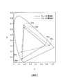
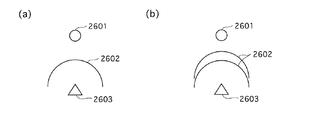
図9は、上記改良型蛍光ランプと上記従来型蛍光ランプのランプ発光のCIE1931色度図を示した図である。さらに詳細に説明すると、上記赤色蛍光体のみを用いた赤色発光する蛍光ランプの光の、液晶表示装置を構成する赤色のフィルタ(以下、「赤色フィルタ」と言う。)透過後の光の色度座標をRで、上記青蛍光体のみを用いた青色発光する蛍光ランプの光の、液晶表示装置を構成する青色フィルタ(以下、「青色フィルタ」と言う。)透過後の光の色度座標をB1でそれぞれ示している。また、従来型蛍光ランプに用いられる上記緑色蛍光体のみをもちいた緑色発光する蛍光ランプの、液晶表示装置を構成する緑色フィルタ(以下、「緑色フィルタ」と言う。)透過後の光の色度座標をG1で、改良型蛍光ランプに用いられる上記緑色蛍光体のみを用いた緑色発光する蛍光ランプの、緑色フィルタ透過後の光の色度座標をG2でそれぞれ示している。ここで、以下、赤色、青色、緑色の各色の蛍光体のみを用いた蛍光ランプを、それぞれ、赤色蛍光ランプ、青色蛍光ランプ、緑色蛍光ランプと言い、全ての蛍光体を用いた白色発光する蛍光ランプを白色蛍光ランプと言うこととする。 FIG. 9 is a diagram showing a CIE1931 chromaticity diagram of lamp emission of the improved fluorescent lamp and the conventional fluorescent lamp. More specifically, the chromaticity of the light after passing through the red filter (hereinafter referred to as “red filter”) constituting the liquid crystal display device of the light of the fluorescent lamp emitting red light using only the red phosphor. The coordinates of the chromaticity coordinates of the light after passing through the blue filter (hereinafter referred to as “blue filter”) constituting the liquid crystal display device of the light of the fluorescent lamp emitting blue light using only the blue phosphor is represented by R. Each is indicated by B1. Further, the chromaticity of light after passing through a green filter (hereinafter, referred to as “green filter”) of a fluorescent lamp that emits green light using only the green phosphor used in the conventional fluorescent lamp and constitutes a liquid crystal display device. The coordinates are indicated by G1, and the chromaticity coordinates of the light after passing through the green filter of the fluorescent lamp that emits green light using only the green phosphor used in the improved fluorescent lamp are indicated by G2. Hereafter, fluorescent lamps using only red, blue, and green phosphors are referred to as red fluorescent lamp, blue fluorescent lamp, and green fluorescent lamp, respectively, and fluorescent light that emits white light using all the phosphors. The lamp is called a white fluorescent lamp.
図9より、改良型蛍光ランプの3つ色度座標値を結んでできる三角形B1−G2−Rの面積は、従来型蛍光ランプの3つ色度座標値を結んでできる三角形B1−G1−Rの面積より大きくすることができ、改良型蛍光ランプは従来型蛍光ランプに比べて色度範囲が拡大しており、色再現性を向上できている。
このように、改良型蛍光ランプは、赤色、青色、緑色の各色発光毎に評価した場合には色度範囲を拡大することができるが、現実に改良型蛍光ランプを液晶表示装置のバックライトユニットの光源として用いると、液晶表示装置からの発光の色度範囲が、上記三角形B1−G2−Rで表される色度範囲より狭くなることを本願の発明者らが見出した。 As described above, the improved fluorescent lamp can expand the chromaticity range when evaluated for each color emission of red, blue, and green, but the improved fluorescent lamp is actually used as a backlight unit of a liquid crystal display device. The inventors of the present application have found that the chromaticity range of light emission from the liquid crystal display device is narrower than the chromaticity range represented by the triangle B1-G2-R.
この点を前述の図9を用いて説明する。図9において、B2で示すのは改良型蛍光ランプから発せられる白色光の青色フィルタ透過後の光の色度座標である。なお、当該白色光の赤色フィルタ、緑色フィルタ透過後の色度座標は、上記R、G2と大差がなかったので、図9においては、それぞれ、R、G2で表示することとした。したがって、図9において、三角形B2−G2−Rの面積が、改良型蛍光ランプの発光が液晶表示装置のカラーフィルタを透過した後の発光の色域面積を表している。 This point will be described with reference to FIG. In FIG. 9, B2 represents the chromaticity coordinates of the light emitted from the improved fluorescent lamp after passing through the blue filter. Note that the chromaticity coordinates of the white light after passing through the red filter and the green filter are not significantly different from those of R and G2, and therefore, are displayed as R and G2, respectively, in FIG. Therefore, in FIG. 9, the area of the triangle B2-G2-R represents the color gamut area of the light emission after the light emission of the improved fluorescent lamp has passed through the color filter of the liquid crystal display device.
図9から、単色の各蛍光ランプの各色光を対応する色のカラーフィルタを透過させて得られる三角形B1−G2−Rの色域面積より、改良型蛍光ランプの白色光を各色のカラーフィルタを透過させて得られる三角形B2−G2−Rの色域面積が小さくなっていることが分かる。これは、図8における青色蛍光体の発光領域と緑色蛍光体の発光領域との重なり領域Dの影響で、青色フィルタを透過する青色光の色度座標が長波長側に移動したためと推測される。 From FIG. 9, from the color gamut area of the triangle B1-G2-R obtained by transmitting each color light of each single color fluorescent lamp through the corresponding color filter, the white light of the improved fluorescent lamp is changed to the color filter of each color. It can be seen that the color gamut area of the triangle B2-G2-R obtained by transmission is small. This is presumably because the chromaticity coordinate of the blue light transmitted through the blue filter has moved to the long wavelength side due to the influence of the overlapping region D of the light emitting region of the blue phosphor and the light emitting region of the green phosphor in FIG. .
本発明は、上記問題を解決したもので、現実に使用される白色光でカラーフィルタを透過させた場合でも、従来よりも色再現性を向できる蛍光ランプと、その蛍光ランプを用いた発光装置及び表示装置を提供するものである。 The present invention solves the above-described problem, and a fluorescent lamp capable of improving color reproducibility as compared with conventional fluorescent lamps even when the color filter is transmitted with white light that is actually used, and a light-emitting device using the fluorescent lamp And a display device.
本発明の蛍光ランプは、内面に蛍光体を含む蛍光体膜が形成されてなる気密封止されたガラス容器を有する蛍光ランプであって、前記蛍光体は、430nm以上460nm以下の波長領域にメイン発光ピークを有し、当該メイン発光ピークのスペクトルの半値幅が50nm以下である青色蛍光体と、510nm以上530nm以下の波長領域にメイン発光ピークを有し、当該メイン発光ピークのスペクトルの半値幅が30nm以下である緑色蛍光体と、600nm以上780nm以下の波長領域に発光ピークを有する赤色蛍光体とを含み、前記青色蛍光体の前記メイン発光ピークの波長と前記緑色蛍光体の前記メイン発光ピークの波長との差は、70nm以上90nm以下であることを特徴とする。 The fluorescent lamp of the present invention is a fluorescent lamp having a hermetically sealed glass container in which a phosphor film containing a phosphor is formed on the inner surface, and the phosphor is mainly used in a wavelength region of 430 nm to 460 nm. A blue phosphor having a light emission peak, the half width of the spectrum of the main light emission peak being 50 nm or less, a main light emission peak in a wavelength region of 510 nm or more and 530 nm or less, and the half width of the spectrum of the main light emission peak being A green phosphor having a wavelength of not less than 30 nm and a red phosphor having an emission peak in a wavelength region of not less than 600 nm and not more than 780 nm, the wavelength of the main emission peak of the blue phosphor and the main emission peak of the green phosphor The difference from the wavelength is 70 nm to 90 nm.
また、本発明の発光装置は、上記本発明の蛍光ランプを複数備えたことを特徴とする。 The light emitting device of the present invention is characterized by comprising a plurality of the fluorescent lamps of the present invention.
また、本発明の表示装置は、画面ユニットと、上記本発明の発光装置とを備えたことを特徴とする。 The display device of the present invention includes a screen unit and the light emitting device of the present invention.
上記した構成により、本発明に係る蛍光ランプは、青色蛍光体と緑色蛍光体のメイン発光ピークのスペクトルの重なり部分が従来よりも少なくなるため、当該重なり部分による上記した悪影響を低減でき、もって、従来よりもカラーフィルタ透過後の色再現性が向上することとなる。 With the configuration described above, the fluorescent lamp according to the present invention has a smaller overlapping portion of the spectrum of the main light emission peak of the blue phosphor and the green phosphor than before, and thus can reduce the above-described adverse effects due to the overlapping portion, The color reproducibility after passing through the color filter is improved as compared with the prior art.
また、本発明に係る蛍光ランプを複数用いて発光装置を構成し、その発光装置を液晶表示装置等に用いることにより、色再現性の高い表示装置が実現できる。 In addition, by forming a light emitting device using a plurality of fluorescent lamps according to the present invention and using the light emitting device for a liquid crystal display device or the like, a display device with high color reproducibility can be realized.
10 蛍光ランプ
13 蛍光体
20 冷陰極蛍光ランプ
101 表示装置
102 蛍光ランプユニット
103 液晶画面ユニットDESCRIPTION OF
<実施の形態1>
(実施の形態1−1)
先ず、本発明の蛍光ランプの実施の形態1−1を説明する。本発明の蛍光ランプは、蛍光体として、430nm以上460nm以下の波長領域に発光ピークを有する青色蛍光体と、510nm以上530nm以下の波長領域に発光ピークを有する緑色蛍光体と、600nm以上780nm以下の波長領域に発光ピークを有する赤色蛍光体とを用いている。これらの蛍光体を用いることにより、蛍光ランプの発光の色域面積を大きくでき、ランプ自体の高色再現性を向上できる。また、青色蛍光体は435nm以上447nm以下の波長領域に発光ピークが存することがさらに好ましく、緑色蛍光体は515nm以上520nm以下の波長領域に発光ピークが存することがさらに好ましい。ここで、各蛍光体の発光ピークの波長は、後述する構成成分の成分比等により調整することができるが、目的とする波長に対して、実際に製造される蛍光体の波長は±2nmの範囲でばらつく。<
(Embodiment 1-1)
First, Embodiment 1-1 of the fluorescent lamp of the present invention will be described. The fluorescent lamp of the present invention is a phosphor having a blue phosphor having an emission peak in a wavelength region of 430 nm to 460 nm, a green phosphor having an emission peak in a wavelength region of 510 nm to 530 nm, and 600 nm to 780 nm. A red phosphor having an emission peak in the wavelength region is used. By using these phosphors, the color gamut area of the fluorescent lamp can be increased, and the high color reproducibility of the lamp itself can be improved. Further, it is more preferable that the blue phosphor has an emission peak in the wavelength region of 435 nm to 447 nm, and the green phosphor more preferably has an emission peak in the wavelength region of 515 nm to 520 nm. Here, the wavelength of the emission peak of each phosphor can be adjusted by the component ratio of the constituent components described later, but the wavelength of the phosphor actually produced is ± 2 nm with respect to the target wavelength. It varies in range.
また、本発明の蛍光ランプは、上記青色蛍光体のメイン発光ピークの波長と上記緑色蛍光体のメイン発光ピークの波長との差を70nm以上90nm以下に設定してある。これにより、青色蛍光体の発光領域と緑色蛍光体の発光領域との重なり領域を無くすか又は小さくできるので、本発明の蛍光ランプの白色光を液晶表示装置等のカラーフィルタを透過させても、表示装置自体の発光の色域面積を維持できるので、高色再現性の低下を防止できる。本明細書において、メイン発光ピークとは、発光強度が最も高い発光ピークをいうものとする。なお、上記青色蛍光体のメイン発光ピークの波長と上記緑色蛍光体のメイン発光ピークの波長との差は、80nm以上90nm以下に設定するのがさらに好ましい。 In the fluorescent lamp of the present invention, the difference between the wavelength of the main emission peak of the blue phosphor and the wavelength of the main emission peak of the green phosphor is set to 70 nm or more and 90 nm or less. Thereby, since the overlapping region of the light emitting region of the blue phosphor and the light emitting region of the green phosphor can be eliminated or reduced, even if the white light of the fluorescent lamp of the present invention is transmitted through a color filter such as a liquid crystal display device, Since the color gamut area of light emission of the display device itself can be maintained, it is possible to prevent the deterioration of high color reproducibility. In the present specification, the main emission peak means an emission peak having the highest emission intensity. The difference between the wavelength of the main emission peak of the blue phosphor and the wavelength of the main emission peak of the green phosphor is more preferably set to 80 nm or more and 90 nm or less.
上記430nm以上460nm以下の波長領域に発光ピークを有する青色蛍光体としては、例えば、ユーロピウム付活ストロンチウム・クロロアパタイト〔Sr10(PO4)6Cl2:Eu2+〕(略号:SCA)、ユーロピウム付活リン酸ストロンチウムカルシウム(Sr,Ca)2P2O7:Eu2+(略号:SPO)等が使用できる。Examples of the blue phosphor having an emission peak in the wavelength region of 430 nm to 460 nm include, for example, europium-activated strontium chloroapatite [Sr 10 (PO 4 ) 6 Cl 2 : Eu 2+ ] (abbreviation: SCA), europium Activated strontium calcium phosphate (Sr, Ca) 2 P 2 O 7 : Eu 2+ (abbreviation: SPO) can be used.
ここで、SCA、SPOの代表的な発光ピーク波長は、それぞれ、447[nm]、435[nm]である。 Here, typical emission peak wavelengths of SCA and SPO are 447 [nm] and 435 [nm], respectively.
また、SCA、SPOは、共付活剤Ca,Baを添加し、当該共付活剤Ca,Baのモル比[mol%]を変化させることにより、発光ピークの波長および後述する半値幅を変化させることができる。 In addition, SCA and SPO change the wavelength of the emission peak and the half-value width described later by adding the coactivators Ca and Ba and changing the molar ratio [mol%] of the coactivators Ca and Ba. Can be made.
上記510nm以上530nm以下の波長領域に発光ピークを有する緑色蛍光体としては、例えば、マンガン付活アルミン酸セリウム・マグネシウム・亜鉛〔Ce(Mg,Zn)Al11O19:Mn2+〕(略号:CMZ)、ユーロピウム・マンガン共付活アルミン酸バリウム・マグネシウム〔BaMg2Al16O27:Eu2+,Mn2+〕、〔BaMgAl10O17:Eu2+,Mn2+〕(略号:BAM−G)、マンガン不活マグネシウムガレート〔MgGa2O4:Mn2+〕(略号:MGM)、マンガン付活ジンクシリケート〔Zn2SiO4:Mn2+〕(略号:ZSM)等が使用できる。Examples of the green phosphor having an emission peak in the wavelength region of 510 nm or more and 530 nm or less include, for example, manganese-activated cerium aluminate / magnesium / zinc [Ce (Mg, Zn) Al 11 O 19 : Mn 2+ ] (abbreviation: CMZ), europium / manganese co-activated barium aluminate / magnesium [BaMg 2 Al 16 O 27 : Eu 2+ , Mn 2+ ], [BaMgAl 10 O 17 : Eu 2+ , Mn 2+ ] (abbreviation: BAM−) G), manganese inactive magnesium gallate [MgGa 2 O 4 : Mn 2+ ] (abbreviation: MGM), manganese activated zinc silicate [Zn 2 SiO 4 : Mn 2+ ] (abbreviation: ZSM), and the like can be used.
ここで、CMZ、BAM−G、ZSMの代表的な発光ピーク波長は、それぞれ、519[nm]、515[nm]、525[nm]である。 Here, typical emission peak wavelengths of CMZ, BAM-G, and ZSM are 519 [nm], 515 [nm], and 525 [nm], respectively.
上記600nm以上780nm以下の波長領域に発光ピークを有する赤色蛍光体としては、例えば、ユーロピウム付活イットリウムオキシサルファイド〔Y2O2S:Eu3+〕(略号:YOS)、ユーロピウム付活リン・バナジン酸イットリウム〔Y(P,V)O4:
Eu3+〕(略号:YPV)、マンガン付活フッ化ゲルマン酸マグネシウム〔3.5MgO・0.5MgF2・GeO2:Mn4+〕(略号:MFG)、ユーロピウム付活バナジン酸イットリウム〔YVO4:Eu3+〕(略号:YVO)、ユーロピウム付活酸化イットリウム〔Y2O3:Eu2+〕(略号:YOX)等が使用できる。Examples of the red phosphor having an emission peak in the wavelength region of 600 nm or more and 780 nm or less include, for example, europium-activated yttrium oxysulfide [Y 2 O 2 S: Eu 3+ ] (abbreviation: YOS), europium-activated phosphorus / vanadine. Yttrium acid [Y (P, V) O 4 :
Eu 3+ ] (abbreviation: YPV), manganese activated magnesium fluoride germanate [3.5 MgO · 0.5 MgF 2 · GeO 2 : Mn 4+ ] (abbreviation: MFG), europium activated yttrium vanadate [YVO 4 : Eu 3+ ] (abbreviation: YVO), europium activated yttrium oxide [Y 2 O 3 : Eu 2+ ] (abbreviation: YOX), and the like can be used.
ここで、YOS、YPV、MFG、YVO、YOXの代表的な発光ピーク波長は、それぞれ、625[nm]、619[nm]、655[nm]、619[nm]、611[nm]である。 Here, typical emission peak wavelengths of YOS, YPV, MFG, YVO, and YOX are 625 [nm], 619 [nm], 655 [nm], 619 [nm], and 611 [nm], respectively.
上記青色蛍光体と上記緑色蛍光体とを組み合わせることにより、青色蛍光体のメイン発光ピークの波長と緑色蛍光体のメイン発光ピークの波長との差を70nm以上90nm以下に設定できる。 By combining the blue phosphor and the green phosphor, the difference between the wavelength of the main emission peak of the blue phosphor and the wavelength of the main emission peak of the green phosphor can be set to 70 nm or more and 90 nm or less.
さらに、上記緑色蛍光体のメイン発光ピークのスペクトルの半値幅は、30nm以下であることが好ましい。これにより、緑色のスペクトルと青色のスペクトルとの重なりを少なくすることができ、色再現性の範囲が広くなる。上記緑色蛍光体中でメイン発光ピークのスペクトルの半値幅が30nm以下の蛍光体としては、MGM、BAM−G、CMZ等が該当する。 Furthermore, the half width of the spectrum of the main emission peak of the green phosphor is preferably 30 nm or less. Thereby, the overlap between the green spectrum and the blue spectrum can be reduced, and the range of color reproducibility is widened. Among the above green phosphors, MGM, BAM-G, CMZ, and the like correspond to phosphors having a half-value width of a main emission peak spectrum of 30 nm or less.
また、上記青色蛍光体のメイン発光ピークのスペクトルの半値幅は、50nm以下であることが好ましい。これにより、緑色のスペクトルと青色のスペクトルとの重なりを少なくすることができ、色再現性の範囲が広くなる。上記青色蛍光体中でメイン発光ピークのスペクトルの半値幅が50nm以下の蛍光体としては、SCA、SBCA、SPO等が該当する。なお、上述したように、SBCA、SPOの半値幅は、前記共付活剤の蛍光体全体に占めるモル比[mol%]によって調整可能である。 Moreover, it is preferable that the half width of the spectrum of the main emission peak of the blue phosphor is 50 nm or less. Thereby, the overlap between the green spectrum and the blue spectrum can be reduced, and the range of color reproducibility is widened. Among the blue phosphors, SCA, SBCA, SPO, and the like correspond to phosphors having a half-value width of a main emission peak spectrum of 50 nm or less. As described above, the FWHM of SBCA and SPO can be adjusted by the molar ratio [mol%] of the coactivator to the entire phosphor.
上記緑色蛍光体として、ユーロピウム・マンガン共付活アルミン酸バリウム・マグネシウム(BAM−G)を用いる場合、BAM−Gに含まれるユーロピウムとマンガンのモル比は、4:6〜1:9であることが好ましい。これにより、さらに輝度を向上できるからである。これは後述する実施例2と実施例3との比較から、上記モル比が上記範囲内であれば、BAM−Gの発光スペクトルをほぼシングルピークにすることができ、緑色のスペクトルと青色のスペクトルとの重なりを少なくすることができ、色再現性の範囲が広くなる。ここで、ほぼシングルピークにしたときの半値幅は、30[nm]である。 When europium / manganese co-activated barium magnesium aluminate (BAM-G) is used as the green phosphor, the molar ratio of europium and manganese contained in BAM-G is 4: 6 to 1: 9. Is preferred. This is because the luminance can be further improved. From the comparison between Example 2 and Example 3 described later, if the molar ratio is within the above range, the emission spectrum of BAM-G can be almost single peak, and the green spectrum and the blue spectrum. And the range of color reproducibility is widened. Here, the full width at half maximum when the peak is substantially single is 30 [nm].
また、上記青色蛍光体、上記緑色蛍光体及び上記赤色蛍光体から選ばれる少なくとも一つは、酸化イットリウム(Y2O3)又は酸化ランタン(La2O3)により被覆することが好ましいが、特に上記緑色蛍光体としてBAM−Gを用いる場合は、その表面を酸化イットリウム又は酸化ランタンにより被覆することが好ましい。BAM−Gは、蛍光ランプのガラス容器に広く使用されているナトリウムガラスに含まれるナトリウムと反応して、BAM−Gの組成が変化し、色度が変化すると考えられるが、BAM−Gの表面を酸化イットリウム又は酸化ランタンで被覆すると、BAM−Gとナトリウムとの反応が防止できると考えられるからである。In addition, at least one selected from the blue phosphor, the green phosphor and the red phosphor is preferably coated with yttrium oxide (Y 2 O 3 ) or lanthanum oxide (La 2 O 3 ). When BAM-G is used as the green phosphor, the surface is preferably coated with yttrium oxide or lanthanum oxide. It is considered that BAM-G reacts with sodium contained in sodium glass widely used in glass containers of fluorescent lamps to change the composition of BAM-G and change chromaticity. This is because it is considered that the reaction between BAM-G and sodium can be prevented by coating with yttrium oxide or lanthanum oxide.
次に、本発明の蛍光ランプの実施の形態を図面に基づき説明する。下記の実施の形態では、冷陰極蛍光ランプの例を示したが、本発明の蛍光ランプは外部電極型蛍光ランプ等についても適用可能である。 Next, an embodiment of the fluorescent lamp of the present invention will be described with reference to the drawings. In the following embodiment, an example of a cold cathode fluorescent lamp has been shown. However, the fluorescent lamp of the present invention can also be applied to an external electrode type fluorescent lamp.
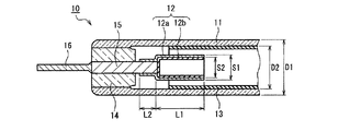
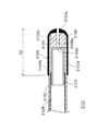
図1は、本発明の蛍光ランプの一例を示す一部拡大断面図である。なお、図1は、蛍光ランプの一端を示したものであり、他端は、図1に示す一端と同様であるため、図示を省略する。 FIG. 1 is a partially enlarged sectional view showing an example of the fluorescent lamp of the present invention. FIG. 1 shows one end of the fluorescent lamp, and the other end is the same as the one end shown in FIG.
図1を参照して、蛍光ランプ10は、ガラス容器11と、ガラス容器11の内部に配置された一対の電極12とを備える。
Referring to FIG. 1, a
ガラス容器11は、例えばホウ珪酸ガラスからなり、その内面には、蛍光体13が塗布されている。ガラス容器11の両端は、ガラスビード14によって封止されている。ガラスビード14によって封止されたガラス容器11の内部には、水銀が2mg封入され、アルゴン、ネオン等の希ガスが60Torrで封入されている。なお、上記希ガスとしては、アルゴンとネオン(Ar−5%、Ne−95%)の混合ガスを用いた。
The
蛍光体13は、前述の430nm以上460nm以下の波長領域に発光ピークを有する青色蛍光体と、510nm以上530nm以下の波長領域に発光ピークを有する緑色蛍光体と、600nm以上780nm以下の波長領域に発光ピークを有する赤色蛍光体とを含む3波長型の蛍光体を用い、上記青色蛍光体のメイン発光ピークの波長と上記緑色蛍光体のメイン発光ピークの波長との差は、70nm以上90nm以下に設定されている。
The
次に、電極12について説明する。電極12は、金属スリーブ12aと、金属スリーブ12aの少なくとも一部に設けられたエミッタ12bとを備える。金属スリーブ12aは、エミッタの焼成温度(例えば、550℃)以上の耐熱性がある金属からなる。金属スリーブ12aの材料としては、例えば、ニッケル、モリブデン、タングステン、チタン、ニオブ等を用いることができる。金属スリーブ12aの一端は、タングステン等からなる内部リード線15に挿入されて溶接されており、内部リード線15はガラスビード14を通って外部リード線16に接続されている。エミッタ12bは、酸化マグネシウム微粒子等とバインダと溶媒とを混合したエミッタ塗布液を、金属スリーブ12aに塗布した後に熱処理することによって形成できる。なお、エミッタは電極外周面に設けてもよい。
Next, the
また、図1では、電極12として、金属スリーブ12aの基部を内部リード線15に挿入して溶接により接合した例を示したが、有底筒状の金属スリーブを用い、その金属スリーブの外底面と内部リード線とを溶接して電極とすることもできる。
1 shows an example in which the base portion of the
なお、ガラス容器11の材質はホウ珪酸ガラスに限らず、鉛ガラス、鉛フリーガラス、ソーダライムガラス等を用いてもよい。この場合に、暗黒始動性が改善できる。即ち、上記したようなガラスは、酸化ナトリウム(Na2O)に代表されるアルカリ金属酸化物を多く
含み、例えば、酸化ナトリウムの場合はナトリウム(Na)成分が時間の経過とともにガラス容器11の内面に溶出する。ナトリウムは電気陰性度が低いため、ガラス容器11の内側端部に溶出したナトリウムが、暗黒始動性の向上に寄与するものと思われる。The material of the
特に、外部電極型蛍光ランプでは、ガラス容器材料におけるアルカリ金属酸化物の含有率は、3[mol%]以上20[mol%]以下が好ましい。 In particular, in the external electrode fluorescent lamp, the alkali metal oxide content in the glass container material is preferably 3 [mol%] or more and 20 [mol%] or less.
例えば、アルカリ金属酸化物が酸化ナトリウムの場合、その含有率は、5[mol%]以上20[mol%]以下が好ましい。5[mol%]未満であると暗黒始動時間が1秒を超える確率が高くなり(換言すると、5[mol%]以上であれば暗黒始動時間が1秒以内になる確率が高くなる)、20[mol%]を超えると、長時間の使用によりガラス容器が黒化(茶褐色化)や白色化して輝度の低下を招いたり、ガラス容器の強度が低下したりするなどの問題が生じるからである。 For example, when the alkali metal oxide is sodium oxide, the content is preferably 5 mol% or more and 20 mol% or less. If it is less than 5 [mol%], the probability that the dark start time will exceed 1 second increases (in other words, if it is 5 [mol%] or more, the probability that the dark start time will be within 1 second increases), 20 If the amount exceeds [mol%], the glass container will be blackened (browned) or whitened due to long-term use, resulting in a decrease in brightness or a decrease in the strength of the glass container. .
また、自然環境保護を考慮した場合、鉛フリーガラスを用いるのが好ましい。但し、鉛フリーガラスは、製造過程で不純物として鉛を含んでしまう場合がある。そこで、0.1重量%以下といった不純物レベルで鉛を含有するガラスも鉛フリーガラスと定義することとする。 In consideration of protection of the natural environment, it is preferable to use lead-free glass. However, lead-free glass may contain lead as an impurity during the manufacturing process. Therefore, glass containing lead at an impurity level of 0.1% by weight or less is also defined as lead-free glass.
また、ガラスの熱膨張係数を調節することにより、冷陰極蛍光ランプのリード線等の封着部材との封着強度を高めることができる。例えば、封着部材がタングステン(W)製の場合には、ガラスの熱膨張係数を36×10-7K-1〜45×10-7K-1とすることが好ましい。この場合、ガラス中のアルカリ金属成分及びアルカリ土類金属成分の合計を4mol%〜10mol%とすることで、ガラスの熱膨張係数を上記の範囲内とすることができる。Further, by adjusting the thermal expansion coefficient of the glass, the sealing strength with a sealing member such as a lead wire of a cold cathode fluorescent lamp can be increased. For example, when the sealing member is made of tungsten (W), it is preferable that the thermal expansion coefficient of the glass is 36 × 10 −7
また、封着部材がコバール(Kovar)製、モリブデン(Mo)製の場合には、45×10-7K-1〜56×10-7K-1とすることが好ましい。この場合、ガラス中のアルカリ金属成分及びアルカリ土類金属成分の合計を7mol%〜14mol%とすることでガラスの熱膨張係数を上記の範囲とすることができる。In the case where the sealing member is made of Kovar or molybdenum (Mo), the sealing member is preferably 45 × 10 −7 K −1 to 56 × 10 −7 K −1 . In this case, the thermal expansion coefficient of glass can be made into said range by making the sum total of the alkali metal component and alkaline-earth metal component in glass into 7 mol%-14 mol%.
また、封着部材がジュメット製の場合には、94×10-7K-1近傍とすることが好ましい。この場合、ガラス中のアルカリ金属成分及びアルカリ土類金属成分の合計を20mol%〜30mol%とすることでガラスの熱膨張係数を上記の範囲とすることができる。Further, when the sealing member is made of Dumet, it is preferably in the vicinity of 94 × 10 −7 K −1 . In this case, the thermal expansion coefficient of glass can be made into said range by making the sum total of the alkali metal component and alkaline-earth metal component in glass into 20 mol%-30 mol%.
また、ガラスに遷移金属の酸化物をその種類によって所定量をドープすることにより、254nmや313nmの紫外線を吸収することができる。具体的には、例えば酸化チタン(TiO2)の場合は、組成比率0.05mol%以上ドープすることにより、254
nmの紫外線を吸収し、組成比率2mol%以上ドープすることにより、313nmの紫外線を吸収することができる。但し、酸化チタンを組成比率5.0mol%より多くドープした場合には、ガラスが失透してしまうため、組成比率0.05mol%以上5.0mol%以下の範囲でドープすることが好ましい。Further, by doping a glass with a predetermined amount of a transition metal oxide depending on the type, ultraviolet rays at 254 nm and 313 nm can be absorbed. Specifically, for example, in the case of titanium oxide (TiO 2 ), 254 is doped by doping at a composition ratio of 0.05 mol% or more.
By absorbing the ultraviolet ray of nm and doping with a composition ratio of 2 mol% or more, the ultraviolet ray of 313 nm can be absorbed. However, when titanium oxide is doped at a composition ratio of more than 5.0 mol%, the glass is devitrified. Therefore, it is preferable to dope in a composition ratio of 0.05 mol% or more and 5.0 mol% or less.
また、酸化セリウム(CeO2)の場合は、組成比率0.05mol%以上ドープする
ことにより、254nmの紫外線を吸収することができる。但し、酸化セリウムを組成比率0.5mol%より多くドープした場合には、ガラスが着色してしまうため、酸化セリウムを組成比率0.05mol%以上0.5mol%以下の範囲でドープすることが好ましい。なお、酸化セリウムに加えて酸化スズ(SnO)をドープすることにより、酸化セリウムによるガラスの着色を抑えることができるため、酸化セリウムを組成比率5.0mol%以下までドープすることができる。この場合、酸化セリウムを組成比率0.5mol%以上ドープすれば313nmの紫外線を吸収することができる。但し、この場合においても酸化セリウムを組成比率が5.0mol%より多くドープした場合には、ガラスが失透してしまう。In the case of cerium oxide (CeO 2 ), ultraviolet rays of 254 nm can be absorbed by doping at a composition ratio of 0.05 mol% or more. However, when cerium oxide is doped at a composition ratio of more than 0.5 mol%, the glass will be colored. Therefore, cerium oxide is preferably doped at a composition ratio of 0.05 mol% or more and 0.5 mol% or less. . Note that, by doping tin oxide (SnO) in addition to cerium oxide, coloring of the glass by cerium oxide can be suppressed, so cerium oxide can be doped to a composition ratio of 5.0 mol% or less. In this case, if cerium oxide is doped with a composition ratio of 0.5 mol% or more, ultraviolet rays of 313 nm can be absorbed. However, even in this case, when the composition ratio of cerium oxide is more than 5.0 mol%, the glass is devitrified.
また、酸化亜鉛(ZnO)の場合は、組成比率2.0mol%以上ドープすることにより、254nmの紫外線を吸収することができる。但し、酸化亜鉛を組成比率10mol%より多くドープした場合、ガラスの熱膨張係数が大きくなり、封着部材がタングステン(W)製である場合に、封着部材の熱膨張係数(約44×10-7K-1)とガラスの熱膨張係数に差異が生じ、封着が困難となるため、酸化亜鉛を2.0mol%以上10mol%以下の範囲でドープすることが好ましい。但し、封着部材がコバール(Koval)製やモリブデン(Mo)製の場合には、封着部材の熱膨張係数(約51×10-7K-1)がタングステン製の場合よりも大きくなるため、酸化亜鉛を組成比率14mol%以下までドープすることができる。さらに、酸化亜鉛を組成比率20mol%より多くドープした場合、ガラスが失透してしまうおそれがあるため、酸化亜鉛を2.0mol%以上20mol%以下の範囲でドープすることが好ましい。In the case of zinc oxide (ZnO), ultraviolet rays of 254 nm can be absorbed by doping at a composition ratio of 2.0 mol% or more. However, when zinc oxide is doped at a composition ratio of more than 10 mol%, the thermal expansion coefficient of the glass increases, and when the sealing member is made of tungsten (W), the thermal expansion coefficient of the sealing member (about 44 × 10 −7 K −1 ) and the glass have a coefficient of thermal expansion, which makes sealing difficult. Therefore, it is preferable to dope zinc oxide in a range of 2.0 mol% to 10 mol%. However, when the sealing member is made of Koval or molybdenum (Mo), the thermal expansion coefficient (about 51 × 10 −7 K −1 ) of the sealing member is larger than that of tungsten. Zinc oxide can be doped to a composition ratio of 14 mol% or less. Furthermore, when zinc oxide is doped at a composition ratio of more than 20 mol%, the glass may be devitrified. Therefore, it is preferable to dope zinc oxide in the range of 2.0 mol% to 20 mol%.
また、酸化鉄(Fe2O3)の場合は、組成比率0.01mol%以上ドープすることにより254nmの紫外線を吸収することができる。但し、酸化鉄を組成比率2.0mol%より多くドープした場合には、ガラスが着色してしまうため、酸化鉄を組成比率0.01mol%以上2.0mol%以下の範囲でドープすることが好ましい。In the case of iron oxide (Fe 2 O 3 ), ultraviolet rays of 254 nm can be absorbed by doping at a composition ratio of 0.01 mol% or more. However, when iron oxide is doped at a composition ratio of more than 2.0 mol%, the glass is colored. Therefore, it is preferable to dope iron oxide in a composition ratio of 0.01 mol% or more and 2.0 mol% or less. .
また、ガラス中の水分含有量を示す赤外線透過率係数は、0.3以上1.2以下の範囲、特に0.4以上0.8以下の範囲となるように調整することが好ましい。赤外線透過率係数が1.2以下であれば、外部電極蛍光ランプ(EEFL)や長尺の冷陰極蛍光ランプ等の高電圧印加ランプに適用可能な低い誘電正接を得やすくなり、0.8以下であれば誘電正接が十分に小さくなって、さらに高電圧印加ランプに適用可能となる。 The infrared transmittance coefficient indicating the water content in the glass is preferably adjusted to be in the range of 0.3 to 1.2, particularly 0.4 to 0.8. When the infrared transmittance coefficient is 1.2 or less, it becomes easy to obtain a low dielectric loss tangent applicable to a high voltage application lamp such as an external electrode fluorescent lamp (EEFL) or a long cold cathode fluorescent lamp, and 0.8 or less. If so, the dielectric loss tangent becomes sufficiently small and can be applied to a high voltage application lamp.
なお、赤外線透過率係数(X)は、下記式(1)で表すことができる。
(数1)
X=〔log(a/b)〕/t (1)
但し、式(1)中で、aは3840cm-1付近の極小点の透過率(%)、bは3560cm-1付近の極小点の透過率(%)、tはガラスの厚みをそれぞれ表す。The infrared transmittance coefficient (X) can be expressed by the following formula (1).
(Equation 1)
X = [log (a / b)] / t (1)
However, in formula (1), a transmittance minimum point near 3840cm -1 (%), b is the transmittance of the minimum point in the vicinity of 3560cm -1 (%), t represents each a thickness of the glass.
また、図1では、直管状の蛍光ランプ10について説明したが、本発明の蛍光ランプは直管状に限らず、「U」字状又は「コ」の字状等の屈曲管であってもよい。また、蛍光ランプ10は、その断面が円形である円筒型ランプに限らす、例えば断面が楕円形を有する偏平型ランプであってもよい。
In addition, although the straight
(実施の形態1−2)
次に、本発明の発光装置と表示装置の実施の形態1−2を図面に基づき説明する。図2は、本発明の蛍光ランプを用いた表示装置101、例えば液晶テレビの概要を示している。(Embodiment 1-2)
Next, Embodiment 1-2 of the light emitting device and the display device of the present invention will be described with reference to the drawings. FIG. 2 shows an outline of a
図2に示す表示装置101は、例えば、32インチの液晶テレビであり、液晶画面ユニット103と、本発明の発光装置である蛍光ランプユニット102とを備えている。液晶画面ユニット103は、例えば、カラーフィルタ基板、液晶、TFT基板、駆動モジュール等(図示せず。)を備え、外部からの画像信号に基づいてカラー画像を形成する。液晶画面ユニット103の下端部には、高周波電子安定器104が配置されており、この高周波電子安定器104によって、蛍光ランプユニット102に備えられた複数本の冷陰極蛍光ランプ20(図1の本発明の蛍光ランプ10に相当)の全ての点灯が行われる。なお、図1において、105は操作ボタン、106はリモコンである。
The
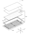
図3は、直下方式の蛍光ランプユニット102の構成を示す概略斜視図である。図3では、内部構造が分かるように前面パネル26の一部が切り欠かれた状態で示されている。蛍光ランプユニット102は、複数の冷陰極蛍光ランプ20と、一方の主面が開口した箱型形状の筐体21と、この筐体21を覆う前面パネル26とを備えている。冷陰極蛍光ランプ20は、直管形状を有し、その軸芯が水平に延伸する状態で、筐体21の短手方向に複数本並設されている。なお、これらの冷陰極蛍光ランプ20は、駆動回路(図示せず。)に接続されており、この駆動回路によって点灯される。
FIG. 3 is a schematic perspective view showing the configuration of the direct type
筐体21は、ポリエチレンテレフタレート(PET)等の樹脂製であって、その内面に銀等の金属が蒸着されて反射面が形成されている。筐体21の開口部は、透光性の前面パネル26で覆われており、内部に埃等の異物が入らないように密閉されている。なお、筐体21は樹脂以外の材料、例えばアルミニウム等の金属材料で構成されていても構わない。前面パネル26は、拡散板23、拡散シート24及びレンズシート25が積層されてなる。
The
拡散板23及び拡散シート24は、冷陰極蛍光ランプ20から発せられた光を散乱・拡散させるものであり、レンズシート25は、当該シート25の法線方向へ光を揃えるものである。これらによって、冷陰極蛍光ランプ20から発せられた光が、前面パネル26の全体に均一に前方方向に照射される。
The
拡散板23の材料は、ポリカーボネート(PC)等の樹脂である。PC樹脂は、耐湿性、機械強度、耐熱性及び光透過性に優れており、PC樹脂製の板は吸湿によって反りを生じることがほとんど無いため、画面サイズが大型(例えば、17インチ以上)な液晶テレビ用の拡散板等の利用にも有益である。
The material of the
以下、本発明の蛍光ランプの一例である冷陰極蛍光ランプについて、実施例を用いて詳細に説明する。 Hereinafter, a cold cathode fluorescent lamp which is an example of the fluorescent lamp of the present invention will be described in detail with reference to examples.
(実施例1)
実施例1では、前述の実施の形態1で説明した蛍光ランプ10の一例について説明する。図1を参照して、蛍光ランプ10は、ニッケルからなる外径(S1)1.7mm、内径(S2)1.5mm、カップ長(L1)5.5mm、基部長(L2)1.5mmの金属スリーブ12aの一端にタングステンからなる外径0.6mmの内部リード線15が挿入され、金属スリーブ12aの一端が圧潰溶接されて両者が接続されている。Example 1
In Example 1, an example of the
ガラス容器11は、外径(D1)2.4mm、内径(D2)2.0mmのホウ珪酸ガラスからなり、ガラス容器11の両端部に電極12が配置されている。電極12は、酸化マグネシウム微粒子からなるエミッタ12bを備えている。
The
また、ガラス容器11の両端部は、ホウ珪酸ガラスからなるガラスビード14で封止されており、内部リード線15は、ガラスビード14を通ってステンレス鋼製の外径0.5mmの外部リード線16に接続されている。一対の電極12の先端間の距離は720mmとした。また、ガラス容器11の内面には蛍光体13を塗布し、その内部には水銀とともにアルゴンとネオンとの混合ガスを8kPaの圧力になるように封入した。
Both ends of the
蛍光体13としては、青色蛍光体がユーロピウム付活ストロンチウム・クロロアパタイト〔Sr10(PO4)6Cl2:Eu2+〕(SCA)、緑色蛍光体がマンガン付活アルミン酸セリウム・マグネシウム・亜鉛〔Ce(Mg,Zn)Al11O19:Eu2+,Mn2+(CMZ)〕及び赤色蛍光体がユーロピウム付活バナジン酸イットリウム〔YVO4:Eu3+〕(YVO)を、SCA:CMZ:YVO=4:2:4の重量比で混合した3波長型の蛍光体を用いた。The
実施例1の蛍光ランプは、以下に示す方法で作製した。 The fluorescent lamp of Example 1 was produced by the following method.
最初に、金属スリーブ12aの内面に、エミッタ12bを以下の方法で形成した。先ず、酸化マグネシウム微粒子10kgを、ニトロセルロース(バインダ)と酢酸ブチル(溶媒)との混合溶液(ニトロセルロース1.5重量%の酢酸ブチル溶液)20リットルに分散させることによって、エミッタ塗布液を調製した。次に、金属スリーブ12aの内面にこのエミッタ塗布液をスプレー法により塗布し、これを空気中で自然乾燥させた。
First, the
その後、エミッタ塗布液を塗布した金属スリーブ12aを、アルゴン雰囲気の還元炉で約550℃に加熱することによって、酸化マグネシウム微粒子を金属スリーブ12へ固着するとともに、バインダ及び溶媒の除去を行い、エミッタ12bを備える電極12を形成した。
Thereafter, the
次に、ガラス容器11の内面に蛍光体13を以下の方法で塗布した。先ず、上記3波長型の蛍光体1kgを、ニトロセルロース(バインダ)と酢酸ブチル(溶媒)との混合溶液(ニトロセルロース1.5重量%の酢酸ブチル溶液)0.6リットルに分散させることによって、蛍光体塗布液を調製した。次に、ガラス容器11を垂下姿勢にして蛍光体塗布液を吸い上げ方式により塗布した後、ガラス容器11内に温風を流して乾燥させた。
Next, the
続いて、電極12を、蛍光体13が塗布されたガラス容器11の両端に配置し、一方の電極12のみを先にガラスビード14を介して加熱封着した。続いて、ガラス容器11の内部に水銀及びアルゴンとネオンとの混合ガスを8kPaになるように導入し、最後に他方の電極12とガラス容器11とをガラスビード14を介して加熱封着して、実施例1の蛍光ランプを作製した。
Subsequently, the
(比較例1)
青色蛍光体としてSCAに代えて、ユーロピウム付活アルミン酸バリウム・マグネシウム〔BaMg2Al16O27:Eu2+〕(BAM−B)を用い、各蛍光体の重量比をBAM−B:CMZ:YVO=4:2:4とした3波長型の蛍光体を用いた以外は、実施例1と同様にして蛍光ランプを作製した。(Comparative Example 1)
Instead of SCA as a blue phosphor, europium-activated barium magnesium aluminate [BaMg 2 Al 16 O 27 : Eu 2+ ] (BAM-B) is used, and the weight ratio of each phosphor is BAM-B: CMZ: A fluorescent lamp was produced in the same manner as in Example 1 except that a three-wavelength phosphor with YVO = 4: 2: 4 was used.
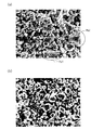
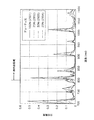
<蛍光ランプの発光スペクトルの測定>
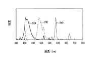
実施例1と比較例1の蛍光ランプに使用した各色蛍光体からなる青色蛍光ランプ、緑色蛍光ランプ、赤色蛍光ランプの単色蛍光ランプを各々作成し、各色蛍光ランプの発光スペクトルを測定した。当該測定には、TOPCON社製の分光分析装置“SR−3”(商品名)を用いた。測定結果をそれぞれ図4(実施例1)及び図5(実施例2)に示す。<Measurement of emission spectrum of fluorescent lamp>
A blue fluorescent lamp, a green fluorescent lamp, and a red fluorescent lamp made of each color phosphor used in the fluorescent lamps of Example 1 and Comparative Example 1 were prepared, and the emission spectra of the fluorescent lamps were measured. For the measurement, a spectroscopic analyzer “SR-3” (trade name) manufactured by TOPCON was used. The measurement results are shown in FIG. 4 (Example 1) and FIG. 5 (Example 2), respectively.
図4(実施例1)から、青色蛍光体SCAのメイン発光ピークの波長は447nm、緑色蛍光体CMZのメイン発光ピークの波長は519nm、赤色蛍光体YVOのメイン発光ピークの波長は618nmと求まる。これより、青色蛍光体SCAのメイン発光ピークの波長と緑色蛍光体CMZのメイン発光ピークの波長との差は、72nmとなる。 From FIG. 4 (Example 1), the wavelength of the main emission peak of the blue phosphor SCA is 447 nm, the wavelength of the main emission peak of the green phosphor CMZ is 519 nm, and the wavelength of the main emission peak of the red phosphor YVO is 618 nm. Accordingly, the difference between the wavelength of the main emission peak of the blue phosphor SCA and the wavelength of the main emission peak of the green phosphor CMZ is 72 nm.
また、上記青色蛍光体SCAのメイン発光ピークのスペクトルの半値幅は35[nm]であり、上記緑色蛍光体CMZのメイン発光ピークのスペクトルの半値幅は30[nm]である。 The half width of the main emission peak spectrum of the blue phosphor SCA is 35 [nm], and the half width of the main emission peak spectrum of the green phosphor CMZ is 30 [nm].
図5(比較例1)から、青色蛍光体BAM−Bのメイン発光ピークの波長は450nm、緑色蛍光体CMZのメイン発光ピークの波長は519nm、赤色蛍光体YVOのメイン発光ピークの波長は618nmと求まる。これより、青色蛍光体BAM−Bのメイン発光ピークの波長と緑色蛍光体CMZのメイン発光ピークの波長との差は、69nmとなる。 From FIG. 5 (Comparative Example 1), the wavelength of the main emission peak of the blue phosphor BAM-B is 450 nm, the wavelength of the main emission peak of the green phosphor CMZ is 519 nm, and the wavelength of the main emission peak of the red phosphor YVO is 618 nm. I want. Thus, the difference between the wavelength of the main emission peak of the blue phosphor BAM-B and the wavelength of the main emission peak of the green phosphor CMZ is 69 nm.
また、上記青色蛍光体BAM−Bのメイン発光ピークのスペクトルの半値幅は50[nm]である。 The half width of the spectrum of the main emission peak of the blue phosphor BAM-B is 50 [nm].
<色度座標値の測定>
実施例1の各色蛍光体を用いた青色蛍光ランプ、緑色蛍光ランプ、赤色蛍光ランプ、および比較例1の各色蛍光体を用いた青色蛍光ランプ、緑色蛍光ランプ、赤色蛍光ランプの各々について、CIE1931色度図における色度座標値を測定した。当該測定には、大塚電子社製の分光分析装置“MCPD−3000”を用いた。測定結果を表1(実施例1)及び表2(実施例2)に示す。<Measurement of chromaticity coordinate value>
CIE1931 colors for each of the blue fluorescent lamp, green fluorescent lamp, red fluorescent lamp using each color phosphor of Example 1, and the blue fluorescent lamp, green fluorescent lamp, and red fluorescent lamp using each color phosphor of Comparative Example 1 The chromaticity coordinate values in the degree diagram were measured. For the measurement, a spectroscopic analyzer “MCPD-3000” manufactured by Otsuka Electronics Co., Ltd. was used. The measurement results are shown in Table 1 (Example 1) and Table 2 (Example 2).

次に、実施例1と比較例1の白色蛍光ランプの光の、液晶表示装置を構成する各色カラーフィルタ透過後の光に関し、CIE1931色度図における色度座標値を測定した。当該測定には、前記分光分析装置を用いた。測定結果を表3(実施例1)及び表4(比較例1)に示す。
Next, the chromaticity coordinate values in the CIE1931 chromaticity diagram were measured for the light of the white fluorescent lamps of Example 1 and Comparative Example 1 after passing through the color filters constituting the liquid crystal display device. The spectroscopic analyzer was used for the measurement. The measurement results are shown in Table 3 (Example 1) and Table 4 (Comparative Example 1).
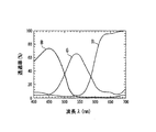
ここで、当該測定に供した各色カラーフィルタの分光分布透過特性を図10に示す。図10おいて、Bは青色フィルタ、Gは緑色フィルタ、Rは赤色フィルタの分光分布透過特性をそれぞれ示す。 Here, the spectral distribution transmission characteristics of each color filter used for the measurement are shown in FIG. In FIG. 10, B shows the spectral distribution transmission characteristics of the blue filter, G shows the green filter, and R shows the red filter.
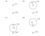
表1〜表4に示す測定結果に基づき、各色の色度座標をCIE1931色度図にプロットし、測定結果毎に、青色、緑色、赤色の色度座標(3点)を実線または破線でむすんだ。図11は、表1、表3に基づいて、図12は、表2、表4に基づいてそれぞれ作成したものである。両図共に、フィルタ透過前(表1、表2)を実線で、フィルタ透過後(表3、表4)を破線でそれぞれ示した。
Based on the measurement results shown in Tables 1 to 4, the chromaticity coordinates of each color are plotted on the CIE1931 chromaticity diagram, and the blue, green, and red chromaticity coordinates (three points) are shown by solid lines or broken lines for each measurement result. It is. 11 is created based on Table 1 and Table 3, and FIG. 12 is created based on Table 2 and Table 4, respectively. In both figures, the solid line before the filter transmission (Tables 1 and 2) and the broken line after the filter transmission (Tables 3 and 4) are shown.
図12に示すように、青色に関し、比較例1においては、フィルタ透過後の色度座標(Bha)が、フィルタ透過前の色度座標(Bhb)に対して、大きく変位しており、これが色度図上の三角形の面積が大きくならない(すなわち、色再現範囲が大きくならない。)原因となっているのは、既述した通りである。これに対し、図11から、実施例1においては、フィルタ透過後の色度座標(Bja)は、フィルタ透過前の色度座標(Bjb)に対して、それほど変位しておらず、色度図上の三角形の面積を大きく減らす原因にはなっていない。 As shown in FIG. 12, with respect to blue, in Comparative Example 1, the chromaticity coordinates (Bha) after passing through the filter are greatly displaced from the chromaticity coordinates (Bhb) before passing through the filter. As described above, the area of the triangle on the degree diagram does not increase (that is, the color reproduction range does not increase). On the other hand, from FIG. 11, in Example 1, the chromaticity coordinates (Bja) after the filter transmission are not so displaced with respect to the chromaticity coordinates (Bjb) before the filter transmission. It does not cause a significant reduction in the area of the upper triangle.
なお、実施例1、比較例1共に、緑色、赤色に関しては、フィルタ透過前の色度座標(Gjb=Ghb)、(Rjb=Rhb)に対し、フィルタ透過後の色度座標(Gja)、(Gha)、(Rja)、(Rha)は、いずれも色度図上の三角形の面積を増大する方向に変位している。 In both Example 1 and Comparative Example 1, for green and red, chromaticity coordinates (Gja) after transmission through the filter (Gjb = Ghb), (Rjb = Rhb), and chromaticity coordinates (Gja), (after transmission through the filter) Gha), (Rja), and (Rha) are all displaced in the direction of increasing the area of the triangle on the chromaticity diagram.
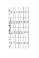
ここで、図11、図12に示した各三角形の面積を、CIE1931色度図内におけるNTSC規格の3原色の色度座標値を結ぶNTSC三角形(NTSCトライアングル)の面積を基準(100%)とした面積比(NTSC比)で表した。当該面積比を表5に示す。 Here, the area of each triangle shown in FIGS. 11 and 12 is defined as the reference (100%) of the area of the NTSC triangle (NTSC triangle) connecting the chromaticity coordinate values of the three primary colors of the NTSC standard in the CIE1931 chromaticity diagram. Expressed as an area ratio (NTSC ratio). The area ratio is shown in Table 5.
(実施例2)
緑色蛍光体としてCMZに代えて、ユーロピウム・マンガン共付活アルミン酸バリウム・マグネシウム〔BaMg2Al16O27:Eu2+,Mn2+〕(BAM−G)を用い、各蛍光体の重量比をSCA:BAM−G:YVO=4:2:4とした3波長型の蛍光体を用いた以外は、実施例1と同様にして蛍光ランプを作製した。但し、BAM−Gに含まれるユーロピウム(Eu2+)とマンガン(Mn2+)のモル比は、1:9とした。(Example 2)
Instead of CMZ as a green phosphor, europium / manganese co-activated barium aluminate / magnesium [BaMg 2 Al 16 O 27 : Eu 2+ , Mn 2+ ] (BAM-G) was used, and the weight ratio of each phosphor Was used in the same manner as in Example 1 except that a three-wavelength phosphor with SCA: BAM-G: YVO = 4: 2: 4 was used. However, the molar ratio of europium (Eu 2+ ) and manganese (Mn 2+ ) contained in BAM-G was 1: 9.
(実施例3)
BAM−Gに含まれるユーロピウム(Eu2+)とマンガン(Mn2+)とのモル比を5:5とした以外は、実施例2と同様にして蛍光ランプを作製した。(Example 3)
A fluorescent lamp was produced in the same manner as in Example 2 except that the molar ratio of europium (Eu 2+ ) and manganese (Mn 2+ ) contained in BAM-G was 5: 5.
実施例2と実施例3の蛍光ランプの発光スペクトルを前述と同様にして測定した。その結果を図6及び図7に示す。但し、図6及び図7では、緑色(緑色蛍光ランプの光)のスペクトルのみを示し,青色及び赤色のスペクトルは省略した。 The emission spectra of the fluorescent lamps of Example 2 and Example 3 were measured in the same manner as described above. The results are shown in FIGS. However, in FIGS. 6 and 7, only the green spectrum (light of the green fluorescent lamp) is shown, and the blue and red spectra are omitted.
ここで、図6に示す実施例2の発光ピーク波長は515[nm]、その半値幅は30[nm]であり、図7に示す実施例3の発光ピーク波長は515[nm]、その半値幅は30[nm]である。 Here, the emission peak wavelength of Example 2 shown in FIG. 6 is 515 [nm] and its half-value width is 30 [nm], and the emission peak wavelength of Example 3 shown in FIG. The value width is 30 [nm].
次に、実施例2と実施例3の白色蛍光ランプの輝度をTOPCON社製の分光分析装置“SR−3”を用いて測定した。その結果、実施例2の白色蛍光ランプでは、輝度は19325cd/m2であったのに対して、実施例3の白色蛍光ランプでは、18339cd/m2であった。これは、図6、図7から分かるように、実施例2の緑色のスペクトルは、ほぼシングルピークであるのに対して、実施例3の緑色のスペクトルは、図7のW部に示すように、メインピークに加えてサブピークも認められ、このダブルピークの影響で輝度が少し低下したものと考えられる。Next, the luminance of the white fluorescent lamps of Example 2 and Example 3 was measured using a spectroscopic analyzer “SR-3” manufactured by TOPCON. As a result, in the white fluorescent lamp of Example 2, the luminance was 19325 cd / m 2 , whereas in the white fluorescent lamp of Example 3, it was 18339 cd / m 2 . As can be seen from FIGS. 6 and 7, the green spectrum of Example 2 is almost a single peak, whereas the green spectrum of Example 3 is as shown in the W part of FIG. 7. In addition to the main peak, sub-peaks are also observed, and it is considered that the luminance is slightly reduced by the influence of this double peak.
また、実施例2と実施例3の蛍光ランプについて実施例1と同様にしてNTSC比による評価を行ったところ、実施例1と同等以上の高色再現性を実現できていることが確認できた。
<実施の形態2>
実施の形態1では、カラーフィルタ透過後の色再現範囲を従来よりも拡大できるといった、バックライトユニットの光源として好適な蛍光ランプを実現できた。実施の形態2では、蛍光ランプの内でも、細径化に適しているため、薄型化(小型化)が要求されるバックライトユニットの光源として好適な外部電極型蛍光ランプに関するものであり、特に、以下に記す背景技術に鑑み、ガラス容器外面に形成され、外部電極として用いられる導電膜の改良技術に関するものである。Moreover, when the fluorescent lamps of Example 2 and Example 3 were evaluated by NTSC ratio in the same manner as Example 1, it was confirmed that high color reproducibility equivalent to or higher than Example 1 was realized. .
<
In the first embodiment, a fluorescent lamp suitable as a light source of a backlight unit can be realized in which the color reproduction range after passing through the color filter can be expanded as compared with the conventional one.
外部電極型蛍光ランプの構成要素である細径のガラス容器に用いられる材料として、従来、強度の点で優れているホウ珪酸ガラス(硬質ガラス)が使用されている。また、前記ガラス容器外周に金属テープを貼り付けて外部電極を構成している。 Conventionally, borosilicate glass (hard glass), which is excellent in strength, has been used as a material used for a small-diameter glass container that is a constituent element of an external electrode type fluorescent lamp. In addition, an external electrode is configured by attaching a metal tape to the outer periphery of the glass container.
しかし、例えば外径が4mmといったように細いガラス容器に、金属テープを一様に密着させて貼着するのは困難である。これに対処するため、溶融半田にガラス容器端部部分を浸漬して(ディッピング)、ガラス容器表面に半田層を形成し、当該半田層で外部電極を構成することが考えられるが、スズと鉛を主成分とする一般的な半田はガラスに固着しにくく、当該半田で一様な外部電極を形成するのは困難である。 However, it is difficult to attach a metal tape to a thin glass container having an outer diameter of 4 mm, for example, so that the metal tape is uniformly adhered. In order to cope with this, it is conceivable to immerse the end portion of the glass container in molten solder (dipping) to form a solder layer on the surface of the glass container, and to form an external electrode with the solder layer. A general solder containing as a main component is difficult to adhere to glass, and it is difficult to form a uniform external electrode with the solder.
そこで、特開2004−146351号公報には、スズを主成分とし、アンチモン、亜鉛等を添加した半田を用いて、ディッピングにより外部電極を形成する技術(以下、「第1技術」と言う。)が開示されている。 Japanese Patent Application Laid-Open No. 2004-146351 discloses a technique (hereinafter referred to as “first technique”) in which an external electrode is formed by dipping using solder containing tin as a main component and added with antimony, zinc, or the like. Is disclosed.
また、アンチモンは環境負荷物質であるため、これを用いずに外部電極を形成する技術(以下、「第2技術」と言う。)が特開2007−26798号公報に開示されている。第2技術によれば、先ず、銀粉末とガラスフリットを含むペースト(以下、「Agペースト」と称する。)をガラス容器端部外周にコーティングし、これを焼成して銀被膜を形成する。次に、スズを主成分とし銀、銅が添加されてなる半田をディッピングによって前記銀被膜に重ねて半田層を形成し2層構造の外部電極が出来上がる。銀被膜に半田層を重ねるのは、銀被膜が露出していると、空気中の硫黄成分と反応して硫化銀を形成し、導電性が低下するからである。 Further, since antimony is an environmental load substance, a technique for forming an external electrode without using it (hereinafter referred to as “second technique”) is disclosed in Japanese Patent Application Laid-Open No. 2007-26798. According to the second technique, first, a paste containing silver powder and glass frit (hereinafter referred to as “Ag paste”) is coated on the outer periphery of the end portion of the glass container, and this is fired to form a silver film. Next, a solder layer is formed by stacking a solder layer mainly composed of tin and containing silver and copper on the silver film by dipping to form an external electrode having a two-layer structure. The reason why the solder layer is superimposed on the silver coating is that when the silver coating is exposed, it reacts with sulfur components in the air to form silver sulfide, which lowers the conductivity.
ところで、現在、外部電極型放電ランプを構成するガラス容器に使用される材料は、上記したように強度面からホウ珪酸ガラスが主流であるが、コスト面から軟質ガラスを使用したいといった要請がある。 By the way, the material used for the glass container constituting the external electrode type discharge lamp is mainly borosilicate glass from the viewpoint of strength as described above, but there is a demand for using soft glass from the viewpoint of cost.
しかしながら、上記第1および第2のいずれの技術も、外部電極がその構成に半田層を含むため、軟質ガラスからなるガラス容器には向いていないといった問題がある。軟質ガラスは、熱膨張係数が大きいため、溶融半田に浸漬したとたん、急激な温度変化によって割れてしまうからである。 However, both the first and second techniques have a problem that the external electrode is not suitable for a glass container made of soft glass because the structure includes a solder layer. This is because soft glass has a large coefficient of thermal expansion, and as soon as it is immersed in molten solder, it breaks due to a rapid temperature change.
なお、上記した課題は、ガラス容器の両端部分外面に給電端子を有する冷陰極放電ランプにも共通する。当該冷陰極放電ランプは、ガラス容器の両端部分外面に形成された導電膜と、内部電極に接続されたリード線とが電気的に接続されてなるものであり、当該導電膜が給電端子として用いられる放電ランプである。 In addition, the above-mentioned subject is common also to the cold cathode discharge lamp which has a power feeding terminal in the both-ends part outer surface of a glass container. The cold cathode discharge lamp is formed by electrically connecting a conductive film formed on the outer surface of both end portions of a glass container and a lead wire connected to an internal electrode, and the conductive film is used as a power supply terminal. Discharge lamp.
そこで、実施の形態2では、導電膜に半田層を含まない放電ランプを提供することをさらなる目的とする。また、そのような放電ランプを有するバックライトユニット、および当該バックライトユニットを備えた液晶表示装置を提供することを目的とする。 Therefore, a second object of the second embodiment is to provide a discharge lamp in which a conductive layer does not include a solder layer. Moreover, it aims at providing the backlight unit which has such a discharge lamp, and a liquid crystal display device provided with the said backlight unit.
なお、導電膜に半田層を含まないこととすれば、半田工程を省略できるといった利点があることから、ホウ珪酸ガラス(硬質ガラス)からなるガラス容器を有する放電ランプにも有用である。 Note that if the solder layer is not included in the conductive film, there is an advantage that the soldering process can be omitted. Therefore, the conductive film is also useful for a discharge lamp having a glass container made of borosilicate glass (hard glass).
上記の目的を達成するため、実施の形態2に係る放電ランプは、気密封止されたガラス容器と当該ガラス容器の外面に形成された導電膜とを有する放電ランプであって、アルミニウム粉末を主材料、銀粉末を副材料とする混合金属粉末、又はアルミニウムを主成分、銀を副成分とするアルミニウムと銀のアトマイズ合金粉とガラスフリットとを含み前記ガラス容器外面に塗布されたペーストの焼成体で、前記導電膜が構成されていることを特徴とする。
In order to achieve the above object, a discharge lamp according to
また、前記導電膜は、銀を6〜40[Wt%]の範囲で含むことを特徴とする。 Further, the conductive film contains silver in a range of 6 to 40 [Wt%].
さらに、前記ガラス容器が、軟質ガラスからなることを特徴とする。 Furthermore, the glass container is made of soft glass.
上記の目的を達成するため、実施の形態2に係るバックライトユニットは、光源として、上記放電ランプを有することを特徴とする。
In order to achieve the above object, the backlight unit according to
上記の目的を達成するため、実施の形態2に係る液晶表示装置は、液晶表示パネルと、前記液晶表示パネルの背面に配された上記バックライトユニットとを備えることを特徴とする。 In order to achieve the above object, a liquid crystal display device according to a second embodiment includes a liquid crystal display panel and the backlight unit disposed on the back surface of the liquid crystal display panel.
実施の形態2に係る放電ランプによれば、導電膜がペーストの焼成体で構成され、半田層を含まないので、ガラス容器の材料として軟質ガラスを用いることができる。 According to the discharge lamp according to the second embodiment, since the conductive film is formed of a fired paste and does not include a solder layer, soft glass can be used as the material of the glass container.
以下、実施の形態2に係る放電ランプについて、図面を参照しながら詳細に説明する。
(実施の形態2−1)
図13は、放電ランプの一例として示す外部電極型蛍光ランプ510(以下、単に「蛍光ランプ510」と言う。)の概略構成を示す半断面図である。なお、図13を含む全ての図において、各構成部材間の縮尺は統一していない。Hereinafter, the discharge lamp according to
(Embodiment 2-1)
FIG. 13 is a half sectional view showing a schematic configuration of an external electrode type fluorescent lamp 510 (hereinafter simply referred to as “
蛍光ランプ510は、ガラス管の両端が封着されてなるガラス容器512を有する。ガラス容器512の各部寸法の一例を示すと、全長L1は740mmで、外径は4.0mmで、内径は3.0mmである。
The
ガラス容器512は、鉛ガラス、鉛フリーガラス、ソーダライムガラスその他の軟質ガラスからなる。軟質ガラスは、酸化ナトリウム(Na2O)を5[mol%]以上20[mol%]以下の範囲で含有するガラス材料である。軟質ガラスの熱膨張係数は、92〜102×10−7[K−1]の範囲である。本例では、鉛フリーガラス(Na2O含有率5〜12[mol%])を用いている。その熱膨張係数は92.5×10⁻⁷[K−1]であり、また軟化点は680℃である。鉛フリーガラスを用いるのは、自然環境保護を考慮しているからである。ただ、鉛フリーガラスといえども、製造過程で不純物として鉛を含んでしまう場合がある。そこで、0.1[Wt%]以下といった不純物レベルで鉛を含有するガラスも鉛フリーガラスと定義することとする。The
ガラス容器512の両端部外周には、第1外部電極514と第2外部電極516が形成されている。第1および第2外部電極514,516は、例えば幅W1=20mmで、ガラス容器512の全周に渡って形成されている。
A first
第1および第2外部電極514,516は、アルミニウムの粉末を主材料、銀の粉末を副材料とする混合金属粉末と、ガラスフリットとを含むペースト(以下、「Al−Agペースト」と称する。)の焼成体で構成された導電膜からなる。ガラスフリットには、リン酸系のものが用いられる。上記ペーストを焼成すると、混合金属粉末は、溶融し互いに結合してネットワーク状の膜体となる。ガラスフリットは、溶融して前記ネットワークの隙間に入り込むと共に、ガラス容器512表面の微細な凹部に浸入し、いわゆるアンカー効果によって、焼成体を強固にガラス容器512表面に固着させる役割を果たす。なお、ガラスフリットは、リン酸系のものに限らず、ビスマス系のものを用いても構わない。
The first and second
当該Al−Agペーストは、前記混合金属粉末と、前記ガラスフリットと、分散剤としてのエチルセルロースと、溶剤としてのターピネオールとを混合したものである。 The Al-Ag paste is a mixture of the mixed metal powder, the glass frit, ethyl cellulose as a dispersant, and terpineol as a solvent.
ペースト中に占める各材料の割合は、以下の通りである。平均粒径5[μm]のアルミニウム粉末が30[Wt%]以上、平均粒径3[μm]の銀粉末が5〜30[Wt%]、フリットガラスが15〜25[Wt%]で、残部が分散剤・溶剤等である。すなわち、ペーストに含有させる混合金属粉末として、アルミニウム粉末を主材料、銀粉末を副材料としたのである。なお、平均粒径については後述する。 The ratio of each material in the paste is as follows. Aluminum powder with an average particle size of 5 [μm] is 30 [Wt%] or more, silver powder with an average particle size of 3 [μm] is 5 to 30 [Wt%], frit glass is 15 to 25 [Wt%], and the balance Are dispersants and solvents. That is, as the mixed metal powder to be included in the paste, aluminum powder is the main material and silver powder is the secondary material. The average particle size will be described later.
ここで、アルミニウムを主材料に選択したのは、導電性および経済性の観点からである。 Here, aluminum was selected as the main material from the viewpoints of conductivity and economy.
導電性の観点から、アルミニウム粉末が30[Wt%]未満であると、導電膜(第1および第2外部電極514,516)の抵抗値が1×10⁻³[Ω]を超え、蛍光ランプが点灯しにくくなるからである。From the viewpoint of conductivity, when the aluminum powder is less than 30 [Wt%], the resistance value of the conductive film (first and second
また、導電性と経済性を考慮した場合、金属材料としてアルミニウムのみを用いたいのであるが、そうすると、焼成不良が発生する。すなわち、アルミニウムのみであると、焼成の際、ペーストにアルミ酸化膜ができやすく、これが良好な焼成の妨げとなる。アルミ酸化膜を分解するには、焼成温度を750℃まで上げればよいが、軟質ガラスの軟化点はこれよりも低いためガラス容器が変形してしまう。 In consideration of conductivity and economy, it is desirable to use only aluminum as the metal material. That is, when only aluminum is used, an aluminum oxide film is easily formed on the paste during firing, which hinders good firing. In order to decompose the aluminum oxide film, the firing temperature may be increased to 750 ° C. However, the softening point of the soft glass is lower than this, so that the glass container is deformed.
そこで、ペーストの構成材料として銀を加えることとしたのである。銀はアルミニウムよりも酸素と結合し易いので、銀を加えることにより、アルミニウムと酸素との結合を抑制できるからである。なお、酸化銀は150℃程度で分解されるので、銀の酸化膜が発生することはなく、焼成の妨げにはならない。 Therefore, silver was added as a constituent material of the paste. This is because silver is easier to bond with oxygen than aluminum, and the addition of silver can suppress the bond between aluminum and oxygen. Since silver oxide is decomposed at about 150 ° C., a silver oxide film is not generated and does not hinder firing.
ここで、ペースト中に銀を5[Wt%]以上含ませることで、良好な焼成が実現できることが確認されている。換言すると、ペースト中の銀が5[Wt%]未満の場合、焼成不良が発生する。具体的には、ペースト中の銀が5[Wt%]未満の場合、ペースト膜表面に存するアルミニウムに酸化膜が発生するため、ペースト膜内部部分は、いわゆる生焼けになってしまう。その結果、ガラスフリットの溶融が不十分となり、上述したアンカー効果が発揮されなくなって、導電膜(焼成膜)のガラス容器512表面に対する固着力が不十分なものとなってしまう。
Here, it has been confirmed that good baking can be realized by including 5 [Wt%] or more of silver in the paste. In other words, when the silver in the paste is less than 5 [Wt%], defective firing occurs. Specifically, when the silver in the paste is less than 5 [Wt%], an oxide film is generated on aluminum existing on the paste film surface, so that the paste film internal portion becomes so-called burnt. As a result, the frit of the glass frit becomes insufficient, the anchor effect described above cannot be exhibited, and the adhesion force of the conductive film (baked film) to the surface of the
ただし、ペースト中に銀を30[Wt%]を超えて含ませると、背景技術として上述した第2技術の場合と同様、硫化銀の問題が発生する。 However, if silver is included in the paste in excess of 30 [Wt%], the problem of silver sulfide occurs as in the case of the second technique described above as the background art.
したがって、ペースト中に占める銀の割合は、5[Wt%]以上、30[Wt%]以下の範囲で設定することが好ましい。 Therefore, the ratio of silver in the paste is preferably set in the range of 5 [Wt%] to 30 [Wt%].
また、銀とアルミニウムの平均粒径の適切な範囲を以下に示す。ここで、「平均粒径」とは、マイクロトラック粒度分析計で測定した累積グラフにおける50容積%での粒径をいう。 Moreover, the suitable range of the average particle diameter of silver and aluminum is shown below. Here, the “average particle diameter” refers to the particle diameter at 50% by volume in the cumulative graph measured with a Microtrac particle size analyzer.
先ず、銀の適切な平均粒径の範囲は0.2〜10[μm]で、好ましくは1〜5[μm]である。平均粒径が0.2[μm]未満になると、導電膜(第1および第2外部電極514,516)が緻密にならないため、導電性が悪くなる。その結果、蛍光ランプが点灯しにくくなる。一方、平均粒径が10[μm]を超えると、焼成がしにくくなるため、焼成に要する時間が長くなる。その結果、生産性が低下するからである。
First, a suitable average particle diameter range of silver is 0.2 to 10 [μm], preferably 1 to 5 [μm]. When the average particle diameter is less than 0.2 [μm], the conductive film (first and second
次に、アルミニウムの適切な平均粒径の範囲は0.5〜20[μm]で、好ましくは1.5〜10[μm]である。平均粒径が0.5[μm]未満になると、導電膜(第1および第2外部電極514,516)が緻密にならないため、導電性が悪くなる。その結果、蛍光ランプが点灯しにくくなる。一方、平均粒径が20[μm]を超えると、焼成がしにくくなるため、焼成に要する時間が長くなる。その結果、生産性が低下するからである。
Next, a suitable average particle diameter range of aluminum is 0.5 to 20 [μm], preferably 1.5 to 10 [μm]. When the average particle size is less than 0.5 [μm], the conductive film (first and second
続いて、ペースト中に占めるフリットガラスの割合を15〜25[Wt%]の範囲とした理由について説明する。15[Wt%]未満であると、上記アンカー効果が十分に得らないため、導電膜(焼成膜)のガラス容器12表面に対する固着力が不十分なものとなってしまうからであり、25[Wt%]を超えると、導電膜に必要な導電性が得られなくなるからである。
Next, the reason why the ratio of the frit glass in the paste is set in the range of 15 to 25 [Wt%] will be described. If it is less than 15 [Wt%], the anchor effect is not sufficiently obtained, so that the adhesive force of the conductive film (baked film) to the surface of the
なお、ペースト中の分散剤と溶剤とは焼成の際に消散するので、焼成体(外部電極)は、アルミニウム、銀、ガラスでそのほとんどが構成されることとなる。ここで、外部電極(焼成体)に占めるアルミニウム、銀、およびガラスの割合は、アルミニウムが35[Wt%]以上で、銀が6〜40[Wt%]で、残部がガラス等である。 Since the dispersant and solvent in the paste dissipate during firing, most of the fired body (external electrode) is composed of aluminum, silver, and glass. Here, the proportion of aluminum, silver, and glass in the external electrode (fired body) is 35 [Wt%] or more for aluminum, 6 to 40 [Wt%] for silver, and the balance is glass or the like.
また、外部電極(焼成体)における金属成分だけに着目すると、アルミニウムが50[Wt%]以上で、銀が7〜50[Wt%]である。 Further, when focusing only on the metal component in the external electrode (fired body), aluminum is 50 [Wt%] or more and silver is 7 to 50 [Wt%].
第1外部電極514、第2外部電極516は、上記した構成から明らかなように、アンチモン(Sb)、鉛系ガラスフリット等の環境負荷物質を含まずに構成される。
As is clear from the above-described configuration, the first
また、焼成体であるため、軟質ガラスからなるガラス容器(後述するガラス管)が、いわゆる熱割れによって損傷する問題もない。後述するように焼成温度は約620℃と、溶融半田の一般的な温度250℃よりも高いのであるが、焼成の際は、一気に620℃まで加熱するのではなく、徐々に昇温させるため熱割れしないのである。 Moreover, since it is a sintered body, there is no problem that a glass container (glass tube described later) made of soft glass is damaged by so-called thermal cracking. As will be described later, the firing temperature is about 620 ° C., which is higher than the general temperature of molten solder, 250 ° C. However, when firing, the temperature is not increased to 620 ° C. It does not break.
ガラス容器512内周面における、第1外部電極514と対向する部分、および第2外部電極516と対向する部分の少なくとも一部にはそれぞれ、第1保護膜518、第2保護膜520が形成されている。第1および第2保護膜518,520は金属酸化物粒子の集合体からなる。金属酸化物として、本例では、酸化イットリウム(Y2O3)を用いている。なお、金属酸化物としては、これ以外に、例えば、アルミナ(Al2O3)を用いることもできる。なお、保護膜は、図示例のように、外部電極と対向する部分だけではなく、ガラス容器512の略全長に渡って形成することとしても構わない(この場合、後述する蛍光体膜は、保護膜に重ねて形成される。)。保護膜518,520の役割については後述する。A first
ガラス容器512の管軸X方向(長手方向)、第1保護膜518と第2保護膜520の間には、蛍光体膜522が形成されている。蛍光体膜522は、青(B),緑(G),赤(R)の3種希土類蛍光体を含み、全体として白色発光する。例えば、各色蛍光体として上記実施の形態1と同じものを用いることができる。
A
また、気密封止されたガラス容器512内には、所定量の水銀と所定圧の混合希ガスが封入されている。本例では、水銀が約2000μg、混合希ガスとして、約7kPa(20℃)のネオン・アルゴン混合ガス(Ne90%+Ar10%)が封入されている。
A hermetically sealed
上記の構成からなる蛍光ランプ510において、図外のインバータによって第1および第2外部電極514,516に高周波電圧が印加されると、ガラス容器512内の気密封止空間(放電空間)に放電現象が生じて紫外線が放出され、当該紫外線が蛍光体膜522によって可視光に変換されてガラス容器512外へ放出される。前記インバータとして、例えば、最大印加電圧2.5kV、動作周波数60kHzのものを用いることができる。上記放電は誘電体バリア放電である。すなわち、第1および第2外部電極514,516に高周波・高電圧の交流電圧を印加すると、誘電体であるガラス容器512において、第1および第2外部電極の直下のガラスに誘電分極が生じ、その部分の内壁が電極として作用する。これにより、ガラス容器512内に高電圧が導入されて、ガラス容器512内に誘電体バリア放電が生じるのである。このように、誘電体バリア放電とは、放電空間が誘電体(ガラス容器512)に囲まれていて、プラズマに電極が直接さらされない放電である。
In the
電極(外部電極)はプラズマに直接さらされないものの、主として外部電極の配置領域に対応するガラス容器の内周部分は、水銀イオン、ネオンイオン、およびアルゴンイオンの衝撃を受ける。このため、当該衝撃からガラス容器を保護する目的で、上記保護膜518,520が設けられている。
Although the electrode (external electrode) is not directly exposed to the plasma, the inner peripheral portion of the glass container mainly corresponding to the region where the external electrode is disposed is bombarded with mercury ions, neon ions, and argon ions. Therefore, the
続いて、蛍光ランプ510の製造方法について、図14,図15,図16,および図17を参照しながら説明する。
Next, a method for manufacturing the
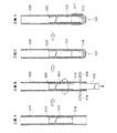
先ず、図14に示すように、管軸に対して垂直に切った断面が円形状であって、全長776[mm]のガラス管530の両端部部分を除くガラス管530内周面に保護膜518,520および蛍光体膜522が形成されてなるものを準備する(工程A)。両端部部分を除いて各種の膜518,520,522を形成するのは、両端部部分にガラス以外の異物があると後述する封着に悪影響を及ぼすからである。
First, as shown in FIG. 14, the cross section cut perpendicularly to the tube axis is circular, and a protective film is formed on the inner peripheral surface of the
次に、ガラス管530の一端部(下端部)をいわゆるドロップシール法によって封着する(工程B,C)。先ず、ガラス管530の一端部から、金属棒532を挿入した後、金属棒532の先端付近のガラス管530を外周からバーナー534,536で加熱する。このとき、ガラス管530は、その管軸周りに回転させると共に、金属棒532を下方へと移動させる(工程B)。金属棒532の外径はガラス管530の内径に近接させているため、先ず、加熱されたガラス管530部分が軟化して、金属棒532に付着する。金属棒532に引っ張られる形で、軟化さらには溶融したガラス管530部分が伸びて、やがてちぎれる。継続して、ガラス管530下端部を加熱すると溶融したガラスが表面張力によって半球状に丸まって封着される(工程C)。この最初に封着された部分を第1封着部537と称することとする。なお、この第1封着工程(工程B,C)は、ガラス管530内外共に大気圧下でなされる。
Next, one end (lower end) of the
続いて、ガラス管530の第1封着部537側端部部分外周に第1外部電極514を形成する(工程D)。先ず、ガラス管530の外周に公知のスクリーン印刷によって、上記Al−Agペーストを塗布する。
Then, the 1st
スクリーン印刷によるAl−Agペーストの塗布工程を、図15を参照しながら簡単に説明する。 The application process of the Al-Ag paste by screen printing will be briefly described with reference to FIG.
スクリーン202が張られた枠204内にAl−Agペースト206を入れる(工程D−1)。
An Al-
一対のゴム製のヘラ208A,208Bを有するスキージ208に対し、枠204を矢印Aの向きに往動させ、ヘラ208AでAl−Agペースト206をスクリーン202における版膜の無い部分202A(以下、「孔部202A」と言う。)に充塞する(工程D−2、D−3)。
The
次に、回転自在に支持されたガラス管530の外周面にスクリーン202を相対的に押し付けた状態で枠204を矢印Bの向きに復動させ、ヘラ208BでAl−Agペースト206をスクリーン202(孔部202A)から押し出して、ガラス管530の外周面に転写する(工程D−4)。このとき、ガラス管530は、スクリーン202に従動して、矢印Cの向きに回転しながら、その外周面にAl−Agペースト206が、所定の厚みで塗布されることとなる。所定の厚みは、約40〜110[μm]の範囲で設定される。
Next, in a state where the
次に、Al−Agペーストの塗布されたガラス管530を焼成炉(不図示)に投入して焼成する。当該焼成工程では、室温から数十分かけて約620℃まで昇温し、当該約620℃で数分間保持した後、また、数十分かけて室温まで冷却する。これにより、平均厚みが20〜80[μm]の範囲の第1外部電極14が形成される。
Next, the
従来、例えば上記第2技術において、焼成による外部電極の形成は、ガラス管530の両端が封着された後、すなわち、ガラス管530の真空引き工程(排気工程)よりも後になされていた。しかしながら、真空引き後に、上記Al−Agペーストを用いて焼成したところ、当該ペーストを塗布したガラス管部分が内向きにへこんでしまうことが判明した。これは、従来のAgペーストでは生じない現象であり(上記第2技術)、Al−Agペーストを用いることにより何らかの原因で、当該ペーストの塗布されたガラス管部分が過熱され、ガラス管内が負圧になっている関係上、大気圧で押されて局部的にへこむものと考えられる。そこで、後述するように、第2外部電極516も含め、実施の形態では、真空引き工程(排気工程)の前に、両外部電極518,520を形成することとしたのである。
Conventionally, in the second technique, for example, the external electrode is formed by firing after both ends of the
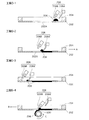
工程Dが終わると、図16に示すように、第1封着部537を上向きにして、未封着の下端部から、鉛フリーガラスからなるビード38を挿入する(工程E)。ビード538は中空円柱状をしており、全長2.0[mm]、外径2.7[mm]、内径1.05[mm]である。ビード538は、金属からなる挿入棒540の上端面に載置され、当該挿入棒540をガラス管530内へと進入させることによって挿入される。挿入棒540は、ガラス管530の内径よりも細い細径部542とガラス管530の外径よりも太い太径部544を有している。細径部542の先端面にビード534が載置された挿入棒540は、太径部544の上端面544Aが、ガラス管530の下端に当接するまで進入される。当接した状態で、ビード538は、その上端(挿入方向先端)が保護膜520から所定距離の位置に位置決めされることとなる。
When step D is completed, as shown in FIG. 16, a bead 38 made of lead-free glass is inserted from an unsealed lower end portion with the
ビード538がガラス管530内へ挿入され、位置決めされた状態で、ビード538の仮止めを行う(工程F)。仮止めとは、ビード538が位置するガラス管530の外周部分をバーナー546,548で加熱して、ビード538の外周の一部または全周をガラス管530内周面に固着することをいう。ビード538の全周が固着されたとしても、ガラス管530の管軸方向の通気性はビード538の中空部538Aによって維持される。
With the
次に、第2外部電極516を形成する(工程G)。第2外部電極516の形成方法は、第1外部電極514(工程D)の場合と同様なので、その説明については、省略する。なお、第1外部電極514は、先に説明したタイミング(工程D)ではなく、この工程Gにおいて、第2外部電極516と同時に形成することとしても構わない。
Next, the second
工程Gが終了すると、ガラス管530の上下を反転させて、水銀ペレット550の投入と希ガスの充填および上端部の仮封着を行う。先ず、ガラス管530の上端から水銀ペレット550を投入する。水銀ペレット50は、チタン−タンタル−鉄の焼結体に水銀を含浸させたものである。続いて、ガラス管530内の排気とガラス管530内への希ガスの充填を行う。具体的には、図示しない給排気装置のヘッドをガラス管530の上端部に装着し、先ず、ガラス管530内を排気して真空にした後、ガラス管530の内圧が約7[kPa]になるまで希ガスを充填する。希ガスが充填されると、その状態のまま、ガラス管530の上端部部分をバーナー552,554で加熱して仮封着する(工程H)。ガラス管530内は、負圧(6.8[kPa])になっているので、バーナー552,554で加熱され軟化または溶融したガラス管530部分は、大気圧に押されて収縮し閉合されて封着されることとなる。
When the process G is finished, the
図17に進み、仮封着に続いて、水銀ペレット550をガラス管530の周囲に配された高周波発振コイル(不図示)によって誘導加熱して水銀を前記焼結体から追い出す。追い出された水銀は、ガラス管530において温度が低い放電空間となる領域(ビード538と第1封着部514との間の空間)へ移動する(工程J)。
Proceeding to FIG. 17, following the temporary sealing, the
工程Jが終了すると、ガラス管530の上下を反転させ、水銀ペレット550をガラス管530内で落下させてビード538から遠ざける。この姿勢で、ガラス管530の第2封着を行う(工程K−1〜3)。ガラス管530を管軸周りに回転させながら、ビード538の下端部近傍のガラス管530部分をその外周からバーナー558,560で加熱する(工程K−1)。ガラス管530内は負圧なので、加熱され軟化したガラス管530部分は大気圧に押されてくびれていく(工程K−2)。さらに加熱を続けると、加熱されたガラス管530部分とビード538は溶融し、溶融したガラス管530の一部がビード538の中空部538Aへ吸い込まれると共に、中空部538Aが収縮する。そして、溶融したガラス管530部分と溶融したビード538とが一体となって封着がなされ、両端部が封着されてなるガラス容器512が完成する(工程K−3)と同時に、蛍光ランプ510が完成する。
When the process J is completed, the
次に、本発明に係る放電ランプを冷陰極蛍光ランプに適用した実施の形態について、図18および図19を参照しながら説明する。
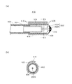
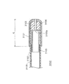
(実施の形態2−2)
図18は、実施の形態に係る冷陰極蛍光ランプ300(以下、単に「蛍光ランプ300」と言う。)の一部を切り欠いた斜視図であり、図19は端部部分の縦断面図である。Next, an embodiment in which the discharge lamp according to the present invention is applied to a cold cathode fluorescent lamp will be described with reference to FIGS.
(Embodiment 2-2)
FIG. 18 is a perspective view in which a part of a cold cathode fluorescent lamp 300 (hereinafter simply referred to as “
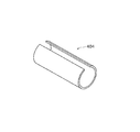
蛍光ランプ300は、円形断面を有するガラス管の両端部がリード線302で気密封止されてなる管状をしたガラス容器304を有する。ガラス容器304は、蛍光ランプ10(図13)と同様、軟質ガラスからなり、寸法の一例を示すと、全長は730mm、外径は4mm、内径は3mmである。
The
ガラス容器304の内部には、約1200μgの水銀(不図示)と、アルゴン(Ar)ガスとネオン(Ne)ガスといった複数種の希ガスからなる混合ガス(不図示)が封入されている。
Inside the
また、ガラス容器304内面には、蛍光体膜306が形成されている。蛍光体膜306は、蛍光ランプ510(図13)と同様の蛍光体で構成される。
A
リード線302は、タングステンからなる内部リード線302Aとニッケルからなる外部リード線302Bの継線である。ガラス管は、内部リード線302A部分で気密封止されている。内部リード線302A、外部リード線302Bは、共に円形断面を有している。内部リード線302Aの線径は0.8mm、全長は3mmで、外部リード線302Bの線径は0.6mm、全長は1mmである。
The
ガラス容器304の端部に支持された内部リード線302Aのガラス容器304内部側端部には、電極308がレーザ溶接等によって接合されている。電極308は、有底筒状をしたいわゆるホロー型電極であり、ニオブ棒を加工したものである。電極308として、ホロー型の電極を採用したのは、ランプ点灯中の放電によって生じる電極におけるスパッタリングの抑制に有効であるからである(詳細は、特開2002−289138号公報等を参照。)。
An
また、ガラス容器304の端部外面には、平均厚み50[μm]の給電端子310が形成されている。ここで、「平均厚み」は、ガラス容器304の外面の内、円筒形状が安定している外周面部分のおける厚みの平均をいう。給電端子310とリード線302(外部リード線302B)とは接合され、電気的に接続されている。給電端子310は、蛍光ランプ510の第1および第2外部電極514,516(図13)の場合と同じ成分からなる焼成体で構成された導電膜からなる。
A
両給電端子310を介して給電することにより、両電極308間で放電が生じる。
When power is supplied through both
なお、蛍光ランプ300においては、導電膜を形成するための、ガラス容器304外面へのAl−Agペーストの塗布は、例えば、刷毛塗りによってなされる。あるいは、ガラス容器304の外周面(ストレート部分)への塗布は、上記したスクリーン印刷(図15)によって行い、ガラス管304の端面への塗布は、刷毛塗りによって行うこととしても構わない。
(実施の形態2−3)
実施の形態2−3に係る冷陰極蛍光ランプは、実施の形態2−2に係る蛍光ランプ300に対し、さらに、ガラス容器304の両端部に金属スリーブを嵌着し、当該金属スリーブを給電端子として用いるものである。In the
(Embodiment 2-3)
In the cold cathode fluorescent lamp according to Embodiment 2-3, a metal sleeve is fitted to both ends of the
金属スリーブを設ける主な目的は、以下の通りである。すなわち、近年のバックライトユニットの高輝度化に伴って、冷陰極蛍光ランプに流す電流も増大している。電流が増大すると、電極の発熱量も大きくなる。そして、過熱状態になると、電極におけるスパッタリングが増大したり、ガラス容器のリード線を封着している部分にクラックが入ったりといった問題が生じる。そこで、熱伝導性の良い材料からなる金属スリーブを設け、後述するソケット608(図25)を介して適度に熱を逃がし、過熱状態になるのを防止するためである。 The main purpose of providing the metal sleeve is as follows. That is, with the recent increase in brightness of the backlight unit, the current passed through the cold cathode fluorescent lamp is also increasing. As the current increases, the heating value of the electrode also increases. And if it becomes an overheated state, the problem that the sputtering in an electrode increases or the part which has sealed the lead wire of a glass container will arise. Therefore, a metal sleeve made of a material having good thermal conductivity is provided, and heat is appropriately released through a socket 608 (FIG. 25) described later to prevent overheating.
(実施の形態2−3−1)
図20(a)は、実施の形態2−3−1に係る冷陰極蛍光ランプ402(以下、単に「蛍光ランプ402」と言う。)の端部部分の縦断面図である。なお、図20において、実施の形態2−2に係る蛍光ランプ300と実質的に同じ構成部分には図19におけるのと同じ符号を付して、その詳細な説明については省略する。なお、符号は異なるが、図20に示す焼成体膜410は、図19における給電端子310と同じ導電膜である。実施の形態2−3−1では、後述する金属スリーブが給電端子となるため、名称とその符号を変更したものである。(Embodiment 2-3-1)
FIG. 20A is a longitudinal sectional view of an end portion of a cold cathode fluorescent lamp 402 (hereinafter simply referred to as “
蛍光ランプ402は、図21に示すような金属スリーブ404を有している。金属スリーブ404は、図20(a)に示すように、ガラス容器304に焼成体膜410を介して嵌着されている。金属スリーブ404の材質は、熱伝導性の観点から、銅や42アロイ(Fe−Ni42合金)が好ましいがこの他、モリブデン、タングステン、コバール等を用いても構わない。
The
金属スリーブ404は、金属帯材を「C」字断面になるように丸めたものであり、嵌着前の内径がガラス容器304の外径よりも小さくなっている。金属スリーブ404は、ガラス容器304に嵌着されると、径方向外方へ弾性変形し、その復元力で焼成体膜410に密着して、ガラス容器304に保持される。
The
金属スリーブ404は、単に嵌着しただけであると、ガラス容器304に対しその管軸方向に移動してしまうおそれがある。そこで、金属スリーブ404の両端部に半田合金を溶着させて、これを金属スリーブ404の移動止めストッパーとしている。
If the
図20(a)におけるA部とB部の拡大図を、図20(b)と図20(c)にそれぞれ示す。 Enlarged views of A part and B part in FIG. 20A are shown in FIG. 20B and FIG. 20C, respectively.
図20(b)に示すように、金属スリーブ404に一端部に半田合金が溶着されてなる半田合金部406が形成されている。一方、図20(c)に示すように、金属スリーブ404の他端部にも半田合金が溶着されてなる半田合金部408が形成されている。金属スリーブ404は、ガラス容器304の円筒形状の安定したストレート部から少し突出して設けられており、半田合金部408は、ガラス容器304の径方向における、金属スリーブ404と焼成体膜410の間隙を埋めるように設けられている。
As shown in FIG. 20B, a
半田合金部406,408は、ビスマスが30〜70[Wt%]の範囲で含まれ、銅が0.01〜2[Wt%]の範囲で添加され、残部が錫からなる低融点半田で構成される。ここで、低融点半田とは、250[℃]以下の融点を持つ半田のことである。低融点半田を用いたのは、ガラス容器に軟質ガラスを用いた場合の熱割れを回避するためである。
当該低融点半田はクリームの形態のものを用いる。この低融点クリーム半田を、図20に示す部位に刷毛塗り等した後、リフロー炉に投入し、投入前の室温から約270[℃]まで加熱し溶融させて、金属スリーブ404に溶着させる。
The low melting point solder is in the form of cream. This low-melting-point cream solder is brushed on the portion shown in FIG. 20 and then put into a reflow furnace, heated from room temperature before the injection to about 270 [° C.], melted, and welded to the
金属スリーブ404の両端に溶着した半田合金部406,408は、金属スリーブ404のガラス容器304の管軸方向へ移動を規制するストッパーとして機能する。
The
(実施の形態2−3−2)
実施の形態2−3−1では、金属スリーブ404の両端部に半田合金部406,408を設けて、金属スリーブ404の移動止めにしたが、実施の形態2−3−2では、金属スリーブ404内面の略全面と焼成体膜410との間に半田合金の溶着層を形成することとした。(Embodiment 2-3-2)
In the embodiment 2-3-1,
図22(a)に、実施の形態2−3−2に係る冷陰極蛍光ランプ412(以下、単に「蛍光ランプ412」と言う。)の端部部分の縦断面図を、図22(b)に、図22(a)におけるC・C線断面図をそれぞれ示す。なお、図22において、実施の形態2−3−1に係る蛍光ランプ402と実質的に同じ構成部分には図20におけるのと同じ符号を付して、その詳細な説明については省略する。
FIG. 22A is a longitudinal sectional view of an end portion of a cold cathode fluorescent lamp 412 (hereinafter simply referred to as “
蛍光ランプ412は、金属スリーブ404と焼成体膜410との間に半田合金層414を有している。半田合金層414は、半田合金の溶着層であり、実施の形態2−3−1と同じ低融点半田で構成される。
The
当該低融点半田はシート形態のものを用いる。この低融点半田シートをガラス容器304に巻きつけた後、金属スリーブ404を嵌着する。そして、実施の形態2−3−1と同様、リフロー炉に投入し、投入前の室温から約270[℃]まで加熱し溶融させて、金属スリーブ404に溶着させる。
The low melting point solder is in the form of a sheet. After the low melting point solder sheet is wound around the
焼成体膜410の主成分がアルミニウムであるため、当該低融点半田は焼成体膜410との溶着性が悪い。しかし、溶融した低融点半田が焼成体膜410表面の微細な凹凸に入り込んだ形で固化して半田合金層414となるため、半田合金層414は金属スリーブ404がガラス容器304の管軸方向へ移動を規制するストッパーとして機能する。
Since the main component of the fired
(実施の形態2−3−3)
実施の形態2−3−1,2−3−2の金属スリーブ404は、横断面が「C」字状をしているため、ガラス容器304の全周を覆っていないが、実施の形態2−3−3では、金属スリーブをガラス容器304の全周を覆うものとした。(Embodiment 2-3-3)
The
図23(a)に、実施の形態2−3−3に係る冷陰極蛍光ランプ416(以下、単に「蛍光ランプ416」と言う。)の端部部分の縦断面図を、図23(b)に、図23(a)におけるD・D線断面図をそれぞれ示す。なお、図23において、実施の形態2−3−1に係る蛍光ランプ402と実質的に同じ構成部分には図20におけるのと同じ符号を付して、その詳細な説明については省略する。
FIG. 23A is a longitudinal sectional view of an end portion of a cold cathode fluorescent lamp 416 (hereinafter simply referred to as “
図23(b)に示すように、実施の形態2−3−3の金属スリーブ418は、ガラス容器304の周方向、両端部の一部が重なり合っていて、ガラス容器304を全周に渡り完全に覆っている。このように、全周を覆うことで、さらに放熱性が改善されることとなる。
As shown in FIG. 23 (b), the
金属スリーブ418内周の略全面には、半田合金層420が形成されている。
A
半田合金層420は、実施の形態2−3−2と同様、低融点半田シートをもちいて形成することができる。この場合は、嵌着前の金属スリーブ418の内周面に低融点半田シートを貼着しておき、金属スリーブ418を半田シートごとガラス容器304に嵌着する。そして、実施の形態2−3−1,2−3−2と同様、リフロー炉に投入し、半田シートを、投入前の室温から約270[℃]まで加熱し溶融させて、金属スリーブ418に溶着させる。
The
なお、半田合金層420が、金属スリーブ418のガラス容器304の管軸方向へ移動を規制するストッパーとして機能することは、実施の形態2−3−2と同様である。
It is to be noted that the
(変形例1)
図24(a)に、実施の形態2−3−3の変形例1に係る冷陰極蛍光ランプ422(以下、単に「蛍光ランプ422」と言う。)の端部部分の縦断面図を示す。(Modification 1)
FIG. 24A shows a longitudinal sectional view of an end portion of a cold cathode fluorescent lamp 422 (hereinafter simply referred to as “
蛍光ランプ422は、金属スリーブ424をガラス容器304の端部よりも突出させ、突出部分の内側を半田合金層426で充填させた点が、蛍光ランプ416(図23)と異なっている。
The
このようにすることで、ガラス容器304の端部からの放熱性が改善されることとなる。
By doing in this way, the heat dissipation from the edge part of the
なお、変形例1の場合は、低融点半田シートのみでは金属スリーブ424端部内側を半田合金層426で埋め尽くせないため、不足部分は、前記した低融点クリーム半田で補うこととしている。
In the case of the first modification, the inner side of the end portion of the
なお、金属スリーブ424の横断面形状は、図23(b)に示す実施の形態2−3−3の金属スリーブ418の横断面形状と同じである。
Note that the cross-sectional shape of the
(変形例2)
図24(b)に、実施の形態2−3−3の変形例2に係る冷陰極蛍光ランプ428(以下、単に「蛍光ランプ428」と言う。)の端部部分の縦断面図を示す。(Modification 2)
FIG. 24B shows a longitudinal sectional view of an end portion of a cold cathode fluorescent lamp 428 (hereinafter simply referred to as “
変形例1の蛍光ランプ422では、半田合金層426の端面を平坦面にしたのに対し(図19(a)参照)、変形例2の蛍光ランプ428は、半田合金層430の端面を凹面状にした点が変形例1と個と異なっている。
In the
このように、凹面状とすることにより、放熱面積が増大することとなるため、空気を介しての放熱性が改善されることとなる。
<実施の形態2−4>
図25に、実施の形態に係るバックライトユニット600の分解斜視図を示す。図25に示すように、バックライトユニット600は、直下方式であり、一つの面が開口した扁平な直方体状の筐体602と、この筐体602の内部に収納された複数の蛍光ランプ60と、筐体602の開口を覆う光学シート類604とを備えている。バックライトユニット600は、液晶パネル(図示せず)の背面に配置され、液晶表示装置における光源装置として用いられる。Thus, since it becomes a concave shape, since the heat radiation area will increase, the heat dissipation through air will be improved.
<Embodiment 2-4>
FIG. 25 is an exploded perspective view of the
筐体602は、例えばポリエチレンレンテレフタレート(PET)樹脂製であって、その内面に銀やアルミニウムなどの金属が蒸着されて反射面606が形成されている。なお、筐体602の材料としては、樹脂以外の材料、例えば、アルミニウムや冷間圧延材(例えばSPCC)等の金属材料により構成しても良い。また、内面の反射面606として金属蒸着膜以外に、例えばポリエチレンレンテレフタレート(PET)樹脂に炭酸カルシウム、二酸化チタン(TiO2)等を添加することにより反射率を高めた反射シートを筐体602に貼付して構成してもよい。The
筐体602の内部には、例えば、実施の形態2−1に係る蛍光ランプ510、1組のソケット608および1組のカバー610が配置されている。
In the
1組のソケット608は、筐体602の長手方向に間隔を空け、略平行に配されている。
The pair of
ソケット608は、例えばリン青銅等の銅合金製の板材(帯材)を加工したものであって、蛍光ランプ510の外部電極514(516)が嵌め込まれる一対の挟持片608Aと、これら隣り合う挟持片608A同士を下端縁で電気的に連結する連結片608Bと、が筐体602の短手方向に連続したものからなる。一対の挟持片608Aに蛍光ランプ510の外部電極514(516)を嵌め込めば、一対の挟持片608Aによって蛍光ランプ510が保持されるとともに、一対の挟持片608Aと外部電極部514(516)とが電気的に接続される。そして、一対のソケット608に取り付けられた蛍光ランプ510には、バックライトユニット600の点灯回路(不図示)からソケット608を介して電力が供給される。
The
カバー610は、一対の挟持片608Aとこれに隣接する一対の挟持片608Aとの間の絶縁性を確保するためのものである。
The
光学シート類604は、例えば、拡散板612、拡散シート614およびレンズシート616により構成されている。拡散板612は、例えば、ポリメタクリル酸メチル(PMMA)樹脂製の板状体であって、筐体602の開口部を塞ぐように配置されている。拡散シート614は、例えばポリエステル樹脂製である。レンズシート616は、例えばアクリル系樹脂とポリエステル樹脂の貼り合せである。これらの光学シート類604は、それぞれ拡散板612に順次重ね合わせるようにして配置されている。
The optical sheets 604 include, for example, a
なお、バックライトユニット600を用いて、実施の形態1と同様に液晶表示装置を構成することも可能である。
Note that the
以上、本発明を実施の形態2に基づいて説明してきたが、上記した形態に限らないことは勿論であり、例えば、以下の形態とすることも可能である。
(1)上記実施の形態では、ガラス容器の材料として軟質ガラスを用いたが、これに限らず、ホウ珪酸ガラスその他の硬質ガラスを用いることとしても構わない。The present invention has been described based on the second embodiment. However, the present invention is not limited to the above-described form, and for example, the following form may be adopted.
(1) In the said embodiment, although soft glass was used as a material of a glass container, it does not matter as not only this but using borosilicate glass and other hard glass.
硬質ガラスを用いた場合、従来の上記した第1技術、第2技術によって金属テープ以外で外部電極を形成することは、既に実現されている。 In the case of using hard glass, it has already been realized to form external electrodes other than metal tape by the conventional first and second techniques described above.
しかし、第1技術によれば外部電極は環境負荷物質を含むが、実施の形態の技術によればこれを含まず、第2技術によれば焼成とディッピングの2工程が必要となるところ、実施の形態の技術によれば、焼成の1工程のみで済むことから、硬質ガラスを用いた場合にもその利点は大きい。
(2)ガラス容器の材料に軟質ガラスを用いた場合には、暗黒始動性が改善できる。すなわち、軟質ガラスは、既述したように酸化ナトリウム(Na2O)に代表されるアルカリ金属酸化物を多く含み、例えば、酸化ナトリウムの場合はナトリウム(Na)成分が時間の経過とともにガラス容器内面に溶出する。ナトリウムは電気陰性度が低いため、ガラス容器内側端部に溶出したナトリウムが、暗黒始動性の向上に寄与するものと思われるからである。However, according to the first technique, the external electrode includes an environmentally hazardous substance, but according to the technique of the embodiment, this does not include this. According to the second technique, two steps of firing and dipping are required. According to the technique of this form, since only one step of firing is required, the advantage is great even when hard glass is used.
(2) When soft glass is used as the material of the glass container, the dark startability can be improved. That is, the soft glass contains a lot of alkali metal oxides typified by sodium oxide (Na 2 O) as described above. For example, in the case of sodium oxide, the sodium (Na) component is the inner surface of the glass container over time. To elute. This is because sodium has a low electronegativity, and sodium eluted at the inner end of the glass container seems to contribute to the improvement of the dark startability.
特に、外部電極型蛍光ランプでは、ガラス容器材料におけるアルカリ金属酸化物の含有率は、3[mol%]以上20[mol%]以下が好ましい。 In particular, in the external electrode fluorescent lamp, the alkali metal oxide content in the glass container material is preferably 3 [mol%] or more and 20 [mol%] or less.
例えば、アルカリ金属酸化物が酸化ナトリウムの場合、その含有率は、5[mol%]以上20[mol%]以下が好ましい。5[mol%]未満であると暗黒始動時間が1秒を超える確率が高くなり(換言すると、5[mol%]以上であれば暗黒始動時間が1秒以内になる確率が高くなる)、20[mol%]を超えると、長時間の使用によりガラス容器が黒化(茶褐色化)や白色化して輝度の低下を招いたり、ガラス容器の強度が低下したりするなどの問題が生じるからである。 For example, when the alkali metal oxide is sodium oxide, the content is preferably 5 mol% or more and 20 mol% or less. If it is less than 5 [mol%], the probability that the dark start time will exceed 1 second increases (in other words, if it is 5 [mol%] or more, the probability that the dark start time will be within 1 second increases), 20 If the amount exceeds [mol%], the glass container will be blackened (browned) or whitened due to long-term use, resulting in a decrease in brightness or a decrease in the strength of the glass container. .
また、自然環境保護を考慮した場合、鉛フリーガラスを用いるのが好ましい。ただ、鉛フリーガラスといえども、製造過程で不純物として鉛を含んでしまう場合がある。そこで、0.1wt%以下といった不純物レベルで鉛を含有するガラスも鉛フリーガラスと定義することとする。
(3)実施の形態では、ランプ形状を直管状とした(図13,図18)。しかしながら、本発明は、「U」字状、「コ」字状、あるいは、「L」字状をしたランプにも適用可能である。また、ガラス容器の横断面も円形に限らず、楕円形その他の扁平形状をしていても構わない。
(4)また、本発明は外部電極型放電ランプや冷陰極放電ランプに限らず、他の電極形式の放電ランプにも適用可能である。要は、気密封止されたガラス容器の外面に導電膜が形成され、当該導電膜を介して給電するような構成とした放電ランプであれば構わないのである。
(5)上記実施の形態では、バックライトユニットの光源として蛍光ランプ510(図13)を用いたが、蛍光ランプ300(図18,図19)、蛍光ランプ402(図20)、蛍光ランプ412(図22)、蛍光ランプ416(図23)、蛍光ランプ422(図24(a))、蛍光ランプ428(図24(b))を用いても構わない。
(6)外部電極514,516、焼成体膜410を構成する導電膜を形成するためのペーストには、アルミニウム粉末と銀粉末とを含む混合金属粉末を用いたが、これに限らず、アルミニウムを主成分、銀を副成分とするアルミニウムと銀のアトマイズ合金粉を用いても構わない。アトマイズ合金粉を用いる場合の、アルミニウム成分と銀成分のペースト中に占める重量%[Wt%]の範囲は、混合金属粉末を用いる場合の上記した重量%の範囲と同じである。すなわち、アルミニウム成分が30[Wt%]以上、銀成分が5〜30[Wt%]、フリットガラスが15〜25[Wt%]で、残部が分散剤・溶剤等である。In consideration of protection of the natural environment, it is preferable to use lead-free glass. However, even lead-free glass may contain lead as an impurity in the manufacturing process. Therefore, glass containing lead at an impurity level of 0.1 wt% or less is also defined as lead-free glass.
(3) In the embodiment, the lamp shape is a straight tube (FIGS. 13 and 18). However, the present invention is also applicable to a lamp having a “U” shape, a “U” shape, or an “L” shape. Further, the cross section of the glass container is not limited to a circle, and may be an oval or other flat shape.
(4) The present invention is not limited to external electrode type discharge lamps and cold cathode discharge lamps, but can be applied to other electrode type discharge lamps. In short, any discharge lamp may be used as long as a conductive film is formed on the outer surface of a hermetically sealed glass container and power is supplied through the conductive film.
(5) Although the fluorescent lamp 510 (FIG. 13) is used as the light source of the backlight unit in the above embodiment, the fluorescent lamp 300 (FIGS. 18 and 19), the fluorescent lamp 402 (FIG. 20), and the fluorescent lamp 412 ( 22), a fluorescent lamp 416 (FIG. 23), a fluorescent lamp 422 (FIG. 24A), and a fluorescent lamp 428 (FIG. 24B) may be used.
(6) Although the mixed metal powder containing aluminum powder and silver powder was used for the paste for forming the conductive electrodes constituting the
したがって、当然のことながら、外部電極(焼成体)、焼成体膜に占めるアルミニウム、銀、およびガラスの割合も、混合金属粉末を用いた場合と同様、アルミニウムが35[Wt%]以上で、銀が6〜40[Wt%]で、残部がガラス等である。 Therefore, as a matter of course, the ratio of aluminum, silver, and glass in the external electrode (fired body) and the fired body film is also 35% [Wt%] or more in the same manner as when the mixed metal powder is used. Is 6 to 40 [Wt%], and the balance is glass or the like.
また、外部電極(焼成体)、焼成体膜における金属成分だけに着目した場合も、混合金属粉末を用いた場合と同様、アルミニウムが50[Wt%]以上で、銀が7〜50[Wt%]である。
<実施の形態3>
実施の形態1では、カラーフィルタ透過後の色再現範囲を従来よりも拡大できるといった、バックライトユニットの光源として好適な蛍光ランプを実現できた。実施の形態3は、以下の背景技術に鑑み、蛍光体膜の製法の起因して生じる管端色度差の改善技術に関する。Further, when attention is paid only to the metal component in the external electrode (fired body) and the fired body film, the aluminum is 50 [Wt%] or more and the silver is 7 to 50 [Wt%] as in the case of using the mixed metal powder. ].
<Embodiment 3>
In the first embodiment, a fluorescent lamp suitable as a light source of a backlight unit can be realized in which the color reproduction range after passing through the color filter can be expanded as compared with the conventional one. The third embodiment relates to a technique for improving the tube end chromaticity difference caused by the phosphor film manufacturing method in view of the following background art.
蛍光ランプにおける管状をしたガラス容器内面への蛍光体膜の形成は、以下のように行われる。 Formation of the phosphor film on the inner surface of the tubular glass container in the fluorescent lamp is performed as follows.
赤色蛍光体粒子、青色蛍光体粒子、緑色蛍光体粒子を含む懸濁液に、垂直に保持したガラス管(前記ガラス容器の素材)の下端部分を浸漬させる。ガラス管の上端部から前記懸濁液を所定の高さまで吸引した後、ガラス管を懸濁液から引き上げる。これにより、余分な懸濁液は自重によりガラス管下端から流出して、ガラス管内面の所定領域に懸濁液が膜状に付着する。そして、ガラス管上端から空気を吹き込んで膜状に付着した懸濁液を乾燥させた後、焼成して蛍光体膜が出来上がる(特開2004−186090号公報)。 The lower end portion of the glass tube (the material of the glass container) held vertically is immersed in a suspension containing red phosphor particles, blue phosphor particles, and green phosphor particles. After the suspension is sucked to a predetermined height from the upper end of the glass tube, the glass tube is pulled up from the suspension. Thereby, the excess suspension flows out from the lower end of the glass tube by its own weight, and the suspension adheres in a film form to a predetermined region on the inner surface of the glass tube. Then, air is blown from the upper end of the glass tube to dry the suspension adhering in the form of a film, followed by firing to obtain a phosphor film (Japanese Patent Laid-Open No. 2004-186090).
しかしながら、上記のようにして作製された蛍光ランプは、管状をしたガラス容器の長手方向に色度差が生じることが知られている。当該色度差の程度は、ガラス容器の両端部分間における色度の差(管端色度差)として評価される。 However, it is known that the fluorescent lamp produced as described above has a chromaticity difference in the longitudinal direction of the tubular glass container. The degree of the chromaticity difference is evaluated as a chromaticity difference (tube end chromaticity difference) between both ends of the glass container.
ところで、液晶テレビに代表される液晶表示装置の近年における高画質化の一環としてなされる高色再現化に伴い、バックライトユニットに使用される蛍光ランプにおいて、再現可能な色度範囲の拡大化の要請、すなわち、CIE1931色度図内において赤・青・緑の各蛍光体の色度値を頂点とするNTS三角(NTSC triangle)を拡張するといった要請がある。また、液晶表示装置の青色カラーフィルターの仕様変更に伴う、蛍光ランプの高色温度化の要請がある。 By the way, along with the high color reproduction that has been made as part of the recent improvement in image quality of liquid crystal display devices represented by liquid crystal televisions, the reproducible chromaticity range has been expanded in fluorescent lamps used in backlight units. There is a request, that is, a request to extend an NTS triangle having the chromaticity values of red, blue, and green phosphors as vertices in the CIE1931 chromaticity diagram. In addition, there is a demand for a higher color temperature of the fluorescent lamp due to a change in the specification of the blue color filter of the liquid crystal display device.
この場合に、青色蛍光体として、従来一般的に用いられているユーロピウム付活アルミン酸バリウム・マグネシウム[BaMg2Al16O27:Eu2+](略号:BAM、色度座標:x=0.148,y=0.055)に代えて、これよりも高色純度のもの(例えば、ユーロピウム付活ストロンチウム・クロロアパタイト[Sr10(PO4)6Cl2:Eu2+](略号:SCA、色度座標:x=0.153,y=0.030)を用いると、管端色度差にそれほど変化は無いものの、肉眼では、問題となるほどの色味の差異が発生する。これは、色度座標が小さくなればなるほど、MacAdamの色識別実験による色差識別長円が小さくなるからである(特に、この場合は、y座標値が強く影響している)。In this case, as a blue phosphor, europium-activated barium magnesium aluminate [BaMg 2 Al 16 O 27 : Eu 2+ ] (abbreviation: BAM, chromaticity coordinates: x = 0.148), which is generally used conventionally. , Y = 0.055), and having a higher color purity (for example, europium activated strontium chloroapatite [Sr 10 (PO 4 ) 6 Cl 2 : Eu 2+ ] (abbreviation: SCA, chromaticity) If coordinates: x = 0.153, y = 0.030), the tube end chromaticity difference does not change so much, but there is a color difference that is problematic for the naked eye. This is because the smaller the coordinate, the smaller the color difference identification ellipse in the MacAdam color identification experiment (particularly, in this case, the y coordinate value has a strong influence).
具体的には、前記製造段階において、懸濁液をガラス管内面に付着させる際に、上側となった端部部分から下側になった端部部分に行くほど青みが強くなっている。 Specifically, in the manufacturing stage, when the suspension is attached to the inner surface of the glass tube, the bluishness becomes stronger as it goes from the upper end portion to the lower end portion.
上記した課題に鑑み、実施の形態3では、管端色度差をさらに抑制した蛍光ランプおよびその製造方法、ならびに、蛍光ランプを用いたバックライトユニット、液晶表示装置を提供することをさらなる目的とする。 In view of the above-described problems, the third embodiment further aims to provide a fluorescent lamp that further suppresses the tube end chromaticity difference, a manufacturing method thereof, a backlight unit using the fluorescent lamp, and a liquid crystal display device. To do.
上記の目的を達成するため、実施の形態3に係る蛍光ランプは、内面に蛍光体膜が形成された管状ガラス容器を有する蛍光ランプであって、前記蛍光体膜は、それぞれ複数の粒子からなる赤色蛍光体、緑色蛍光体、および青色蛍光体を含み、横軸xに青色の蛍光体粒子の粒径[μm]を、縦軸yに対応する粒径の青色の蛍光体粒子が前記青色蛍光体全体に占める体積割合[%]を採ったx−y直交座標系において、当該青色蛍光体が、xが10.8以上の範囲で、y=−0.000007x6+0.0008x5−0.0368x4+0.8326x3−9.1788x2+38.889x+7.092で表される第1の曲線と交差し、当該第1の曲線とy=0.0457x2−2.4896x+33.294で表される第2の曲線とで囲まれる領域を通過して、実質的に、14≦X≦20の範囲でx軸に収束するグラフで表される粒度分布を有することを特徴とする。In order to achieve the above object, the fluorescent lamp according to Embodiment 3 is a fluorescent lamp having a tubular glass container having a phosphor film formed on the inner surface thereof, and each of the phosphor films is composed of a plurality of particles. Including a red phosphor, a green phosphor, and a blue phosphor, the horizontal axis x represents the particle size [μm] of the blue phosphor particle, and the blue phosphor particle having a particle size corresponding to the vertical axis y represents the blue fluorescence. In an xy orthogonal coordinate system that takes a volume ratio [%] of the entire body, the blue phosphor is in a range where x is 10.8 or more, and y = −0.000007x 6 + 0.0008x 5 −0.00. It intersects with the first curve represented by 0368x 4 + 0.8326x 3 −9.1788x 2 + 38.889x + 7.092, and the first curve is represented by y = 0.457x 2 −2.4896x + 33.294. Through the area surrounded by the second curve Thus, the particle size distribution is substantially represented by a graph that converges on the x-axis within a range of 14 ≦ X ≦ 20.
また、上記の目的を達成するため、実施の形態3に係る蛍光ランプは、内面に蛍光体膜が形成された管状ガラス容器を有する蛍光ランプであって、前記蛍光体膜は、それぞれ複数の粒子からなる赤色蛍光体、緑色蛍光体、および青色蛍光体を含み、前記青色蛍光体は、粒径が10[μm]以上30[μm]未満の範囲にある青色蛍光体粒子を、当該青色蛍光体全体に対し19[体積%]含むことを特徴とする。 In order to achieve the above object, the fluorescent lamp according to Embodiment 3 is a fluorescent lamp having a tubular glass container having a phosphor film formed on its inner surface, and each phosphor film has a plurality of particles. A blue phosphor having a particle size in the range of 10 [μm] or more and less than 30 [μm], the red phosphor comprising a red phosphor, a green phosphor, and a blue phosphor It is characterized by including 19 [volume%] with respect to the whole.
上記の目的を達成するため、実施の形態3に係るバックライトユニットは、光源として、上記の蛍光ランプを有することを特徴とする。 In order to achieve the above object, the backlight unit according to Embodiment 3 has the above-described fluorescent lamp as a light source.
上記の目的を達成するため、実施の形態3に係る液晶表示装置は、前記バックライトユニットが前記蛍光ランプを収納する外囲器を有していて、液晶表示パネルと、前記外囲器が前記液晶表示パネルの背面に配されている当該バックライトユニットとを備えることを特徴とする。 In order to achieve the above object, the liquid crystal display device according to the third embodiment includes an envelope in which the backlight unit houses the fluorescent lamp, and the liquid crystal display panel and the envelope are included in the envelope. The backlight unit is provided on the back surface of the liquid crystal display panel.
上記の目的を達成するため、実施の形態3に係る蛍光ランプの製造方法は、複数の粒子からなる赤色蛍光体、緑色蛍光体、および青色蛍光体を含む懸濁液に、ガラス管の第1端部部分が浸漬した状態で第2端部から前記懸濁液を吸い上げる第1工程と、吸い上げた懸濁液の一部をその自重により第1端部部分から流出させる第2工程と、ガラス管内面に膜状に付着して残存する懸濁液を乾燥させた後、焼成して蛍光体膜を形成する第3工程とを含み、前記懸濁液中における青色蛍光体が、横軸xに青色の蛍光体粒子の粒径[μm]を、縦軸yに対応する粒径の青色の蛍光体粒子が前記青色蛍光体全体に占める体積割合[%]を採ったx−y直交座標系において、xが10.8以上の範囲で、y=−0.000007x6+0.0008x5−0.0368x4+0.8326x3−9.1788x2+38.889x+7.092で表される第1の曲線と交差し、当該第1の曲線とy=0.0457x2−2.4896x+33.294で表される第2の曲線とで囲まれる領域を通過して、実質的に、14≦X≦20の範囲でx軸に収束するグラフで表される粒度分布を有することを特徴とする。In order to achieve the above object, a method for manufacturing a fluorescent lamp according to Embodiment 3 is the first method of manufacturing a glass tube in a suspension containing a red phosphor, a green phosphor, and a blue phosphor composed of a plurality of particles. A first step of sucking up the suspension from the second end with the end portion immersed, a second step of causing a portion of the sucked suspension to flow out of the first end portion by its own weight, and glass A third step of drying the suspension remaining attached to the inner surface of the tube in the form of a film, followed by firing to form a phosphor film, wherein the blue phosphor in the suspension is Xy orthogonal coordinate system in which the particle size [μm] of the blue phosphor particles is taken and the volume ratio [%] of the blue phosphor particles having the particle size corresponding to the vertical axis y occupies the entire blue phosphor. In the case where x is in the range of 10.8 or more, y = −0.000007x 6 + 0.0008x 5 −0.03 68x 4 + 0.8326x 3 -9.1788x 2 + 38.889x + 7.092 intersects with the first curve, and the first curve and y = 0.457x 2 -2.4896x + 33.294 It has a particle size distribution represented by a graph that passes through a region surrounded by the second curve and converges substantially on the x-axis within a range of 14 ≦ X ≦ 20.
また、上記の目的を達成するため、実施の形態3に係る蛍光ランプの製造方法は、複数の粒子からなる赤色蛍光体、緑色蛍光体、および青色蛍光体を含む懸濁液に、ガラス管の第1端部部分が浸漬した状態で第2端部から前記懸濁液を吸い上げる第1工程と、吸い上げた懸濁液の一部をその自重により第1端部部分から流出させる第2工程と、ガラス管内面に膜状に付着して残存する懸濁液を乾燥させた後、焼成して蛍光体膜を形成する第3工程とを含み、前記懸濁液中における青色蛍光体は、粒径が10[μm]以上30[μm]未満の範囲にある青色蛍光体粒子を、当該青色蛍光体全体に対し19[体積%]含むことを特徴とする。 In order to achieve the above object, a method for manufacturing a fluorescent lamp according to Embodiment 3 includes a glass tube in a suspension containing a red phosphor, a green phosphor, and a blue phosphor composed of a plurality of particles. A first step of sucking up the suspension from the second end with the first end portion immersed, and a second step of allowing a portion of the sucked suspension to flow out of the first end portion by its own weight; A third step of forming a phosphor film after drying the suspension that remains attached to the inner surface of the glass tube in the form of a film, and the blue phosphor in the suspension is The blue phosphor particles having a diameter in the range of 10 [μm] or more and less than 30 [μm] are contained in 19 [vol%] with respect to the entire blue phosphor.
後述するように、従来、青色蛍光体において10[μm]以上の粒径のものがほとんど含まれないところ、実施の形態3に係る蛍光ランプによれば、10[μm]以上の粒径のものが上記所定量[体積%]含まれているので管端色度差がさらに抑制される。 As will be described later, conventionally, blue phosphors having a particle size of 10 [μm] or more are hardly included, but according to the fluorescent lamp according to Embodiment 3, those having a particle size of 10 [μm] or more are used. Is contained in the predetermined amount [volume%], the tube end chromaticity difference is further suppressed.
以下、実施の形態3について、図面を参照しながら説明する。 Hereinafter, the third embodiment will be described with reference to the drawings.
図26は、実施の形態に係る冷陰極蛍光ランプ710(以下、単に「蛍光ランプ710」と言う。)の概略構成を示す縦断面図である。なお、本図を含む全ての図において、各構成部材間の縮尺は統一していない。
FIG. 26 is a longitudinal sectional view showing a schematic configuration of a cold cathode fluorescent lamp 710 (hereinafter simply referred to as “
蛍光ランプ710は、円形断面を有するガラス管の両端部がリード線712、714で気密封止されてなる管状をしたガラス容器716を有する。ガラス容器716は、硬質のホウケイ酸ガラスからなり、寸法の一例を示すと、全長は900mm、外径は3.4mm、内径は2.4mmである。
The
また、ガラス容器716の内部には、約3mgの水銀(不図示)と、アルゴン(Ar)ガスとネオン(Ne)ガスといった複数種の希ガスからなる混合ガス(不図示)が封入されている。
The
リード線712、714は、それぞれ、タングステンからなる内部リード線712A、714Aとニッケルからなる外部リード線712B、714Bの継線である。なお、外部リード線は、ニッケル合金でも構わない。ガラス管は両端部共、内部リード線712A、714A部分で気密封止されている。内部リード線712A、714A、外部リード線712B、714Bは、共に円形断面を有している。内部リード線712A、714Aの線径は1mm、全長は3mmで、外部リード線712B、714Bの線径は0.8mm、全長は10mmである。
Lead
ガラス容器716の端部に支持された内部リード線712A、714Aのガラス容器716内部側端部には、それぞれ、電極718、720がレーザ溶接等によって接合されている。電極718、720は、有底筒状をしたいわゆるホロー型電極であり、ニオブ棒を加工したものである。電極718、720として、ホロー型の電極を採用したのは、ランプ点灯中の放電によって生じる電極におけるスパッタリングの抑制に有効であるからである(詳細は、特開2002−289138号公報等を参照。)。
また、ガラス容器716内面には、蛍光体膜722が形成されている。蛍光体膜722の平均厚みは、例えば、約20[μm]である。
A
蛍光体膜722は、赤色蛍光体、緑色蛍光体、青色蛍光体を含み、各蛍光体は、無数の(複数個の)粒子からなる。
The
各色蛍光体粒子を形成する蛍光体材料としては、従来、一般的に以下のものが用いられている。なお、本明細書において色度図と言えば、CIE1931色度図を指し、色度座標は、当該色度図での値を指すものとする。 Conventionally, the following materials are generally used as the phosphor material for forming each color phosphor particle. In this specification, a chromaticity diagram refers to a CIE 1931 chromaticity diagram, and chromaticity coordinates indicate values in the chromaticity diagram.
(1)赤色蛍光体材料
ユーロピウム付活酸化イットリウム[Y2O3:Eu3+](略号:YOX)、色度座標:x=0.643,y=0.348
(2)緑色蛍光体材料
セリウム・テルビウム付活リン酸ランタン[LaPO4:Ce3+,Tb3+](略号:LAP)、色度座標:x=0.351,y=0.585
(3)青色蛍光体材料
ユーロピウム付活アルミン酸バリウム・マグネシウム[BaMg2Al16O27:Eu2+](略号:BAM−B)、色度座標:x=0.148,y=0.055
実施の形態では、液晶TVに代表される液晶表示装置を構成するバックライトユニットの光源として冷陰極蛍光ランプを用いる場合に、再現可能な色度範囲を拡大するため、すなわち、色度図内におけるNTSC三角(NTSC triangle)を拡張するため、緑色および青色蛍光体材料として、下記のものを用いている。なお、赤色蛍光体材料は、上記(1)に記載のものと同じである。(1) Red phosphor material Europium activated yttrium oxide [Y 2 O 3 : Eu 3+ ] (abbreviation: YOX), chromaticity coordinates: x = 0.643, y = 0.348
(2) Green phosphor material Cerium / terbium activated lanthanum phosphate [LaPO 4 : Ce 3+ , Tb 3+ ] (abbreviation: LAP), chromaticity coordinates: x = 0.351, y = 0.585
(3) Blue phosphor material Europium-activated barium magnesium aluminate [BaMg 2 Al 16 O 27 : Eu 2+ ] (abbreviation: BAM-B), chromaticity coordinates: x = 0.148, y = 0.055
In the embodiment, when a cold cathode fluorescent lamp is used as a light source of a backlight unit constituting a liquid crystal display device typified by a liquid crystal TV, the reproducible chromaticity range is expanded, that is, in the chromaticity diagram. In order to extend the NTSC triangle, the following materials are used as green and blue phosphor materials. The red phosphor material is the same as that described in (1) above.
(1)緑色蛍光体材料
ユーロピウム・マンガン共付活アルミン酸バリウム・マグネシウム[BaMg2Al16O27:Eu2+,Mn2+](略号:BAM−G)、色度座標:x=0.136,y=0.572
(2)青色蛍光体材料
ユーロピウム付活ストロンチウム・クロロアパタイト[Sr10(PO4)6Cl2:Eu2+](略号:SCA、色度座標:x=0.153,y=0.030)
なお、本明細書で記載している蛍光体(粉体)の色度座標は、大塚電子(株)製の分光分析装置(MCPD−7000)を用いて測定した値を、小数点以下第4桁で四捨五入したものである。(1) Green phosphor material Europium / manganese co-activated barium aluminate / magnesium [BaMg 2 Al 16 O 27 : Eu 2+ , Mn 2+ ] (abbreviation: BAM-G), chromaticity coordinates: x = 0.136 y = 0.572
(2) Blue phosphor material Europium activated strontium chloroapatite [Sr 10 (PO 4 ) 6 Cl 2 : Eu 2+ ] (abbreviation: SCA, chromaticity coordinates: x = 0.153, y = 0.030)
The chromaticity coordinates of the phosphor (powder) described in this specification are values measured using a spectroscopic analyzer (MCPD-7000) manufactured by Otsuka Electronics Co., Ltd. Rounded off.
また、上記した色度座標値は各々の蛍光体材料における代表値であり、測定方法(測定原理)等に起因して、各蛍光体材料が示す色度座標値は、上掲した値と若干異なる場合があり得る。 The chromaticity coordinate values described above are representative values for each phosphor material, and due to the measurement method (measurement principle) and the like, the chromaticity coordinate values indicated by each phosphor material are slightly different from the values listed above. It can be different.
次に、上記構成からなる蛍光ランプ710の製造工程の内、蛍光体膜722の形成に関わる工程について図27を参照しながら説明する。
Next, of the manufacturing processes of the
先ず、工程Aでは、ガラス容器716の素材であるガラス管730の内面に蛍光体粒子を含む懸濁液を付着させる。
First, in step A, a suspension containing phosphor particles is attached to the inner surface of a
具体的には、懸濁液732の入ったタンク734を準備する。懸濁液732は、有機溶媒としての酢酸ブチルの中に、所定量の各色蛍光体粒子、結着剤としてCBBの粒子、増粘剤としてニトロセルロース(NC)を加えたものである。なお、タンク734内の懸濁液732は、不図示の攪拌機によって攪拌され、各種材料が一様に混ざり合った状態になっている。
Specifically, a
そして、ガラス管730を、垂直に立て下端部を懸濁液732に浸した状態で保持する。不図示の真空ポンプの吸引力によって、ガラス管730の上端からガラス管730内を排気し、ガラス管730内を負圧にして懸濁液732を吸い上げる。ガラス管730内の液面が上端に至る途中(所定の高さ)で吸い上げを止めて、ガラス管730を懸濁液732から引き上げる。
Then, the
これにより、余分な懸濁液732が自重によりガラス管730の下端から流出し、ガラス管730内周の所定領域に、懸濁液732が膜状に付着する(工程B)。
Thereby, the
ガラス管730内に乾燥した温風を吹き込んで、膜状に付着した懸濁液732を乾燥させた(工程C)後、工程Dにおいて懸濁液732の吸い込み側となった端部付近の乾燥膜739を一部除去する。
Dry hot air was blown into the
次に、工程Eに示すように、ガラス管730を石英管736に挿入して横たわらせ、石英管736に空気738を送り込みながら、石英管736外部からバーナー740で加熱して、焼成する。この焼成工程の終了によって、ガラス管730内面に蛍光体膜722が形成される。
Next, as shown in step E, the
上記のようにして蛍光体膜を形成すると、既述したように、蛍光ランプ710の発光時に、管状ガラス容器716の管軸方向に色度差が生じる。色度差は、白色を呈するように予め定めた各色蛍光体粒子間の比率(以下、「基準比率」と言う。)が崩れると生じる。当該比率が崩れるのは、以下の理由によるものと考えられている。
When the phosphor film is formed as described above, a chromaticity difference is generated in the tube axis direction of the
工程Aにおいてガラス管730内に吸い上げた懸濁液中における各色蛍光体粒子は、略基準比率で存在するものと考えられる。ところが、工程Bにおいて懸濁液がガラス管730下端から流出する際、各色蛍光体粒子間の大きさや比重の違いに起因して、各色蛍光体粒子間で、ガラス管内壁の付着位置およびその近傍に留まるものや留まらないもので差が生じたり、下方への移動するものの間でその移動速度が揃わなかったりするため、各色蛍光体粒子間の比率が基準比率から崩れるためであると考えられる。
It is considered that each color phosphor particle in the suspension sucked into the
その結果、懸濁液をガラス管内面に付着させる際に、上側になった端部部分では赤みが強くなり下側になった端部部分では青みが強くなっている(即ち、上側になった端部部分から下側になった端部部分に行くほど青みが強くなっている。)。ここで、ガラス管において、懸濁液をガラス管内面に付着させる際に、上側になった端部部分に対応するガラス容器部分を「容器上端部」と称し、下側になった端部部分に対応するガラス容器部分を「容器下端部」と称することとする。なお、容器上端部と容器下端部の色度は、それぞれ、蛍光体膜の対応する端縁から管軸方向中央側へ30[mm]の位置での測定値である。 As a result, when the suspension was attached to the inner surface of the glass tube, redness was strong at the end portion on the upper side, and bluishness was strong at the end portion on the lower side (that is, the upper portion was on the upper side). The bluishness gets stronger as you go from the edge part to the edge part on the lower side.) Here, in the glass tube, when the suspension is attached to the inner surface of the glass tube, the glass container portion corresponding to the upper end portion is referred to as the “upper end portion of the container” and the lower end portion. The glass container part corresponding to is referred to as “container lower end part”. In addition, the chromaticity of the container upper end and the container lower end is a measured value at a position of 30 [mm] from the corresponding edge of the phosphor film toward the center in the tube axis direction.
上記現象が生じるのは、赤色蛍光体粒子と青色蛍光体粒子間の比率のアンバランスが原因であると考え、問題となる程に管端色度差が生じる赤色蛍光体粒子(YOX)と青色蛍光体粒子(SCA)の粒度分布を調べた。その結果を、図28に示す。 The above phenomenon is considered to be caused by an imbalance in the ratio between the red phosphor particles and the blue phosphor particles, and the red phosphor particles (YOX) and the blue phosphor, which cause a tube end chromaticity difference as much as a problem. The particle size distribution of the phosphor particles (SCA) was examined. The result is shown in FIG.
図28に示す粒度分布図において、横軸は、青色蛍光体粒子および赤色蛍光体粒子の粒径[μm]を、縦軸は対応する粒径の蛍光体粒子が各々の蛍光体全体に占める体積割合[%]を示している。図28は、たとえば、大径の粒子と小径の粒子が同数含まれているとすると、大径の粒子径に対応する体積%は、小径の粒子径に対応する体積%よりも高い値を示すといった性質のものである。 In the particle size distribution diagram shown in FIG. 28, the horizontal axis represents the particle size [μm] of the blue phosphor particles and the red phosphor particles, and the vertical axis represents the volume occupied by the phosphor particles having the corresponding particle size in the entire phosphor. The ratio [%] is shown. FIG. 28 shows that, for example, if the same number of large-diameter particles and small-diameter particles are included, the volume% corresponding to the large-diameter particle diameter is higher than the volume% corresponding to the small-diameter particle diameter. It is of the nature.
図28から、最も多くの体積を占める蛍光体粒子の径には大きな差が無いことが分かる。また、赤色蛍光体粒子は、青色蛍光体粒子よりも、径の大きなものが多く含まれていることが分かる。ここで、青色蛍光体材料(SCA)の比重は4.2[g/cm3]であり、赤色蛍光体材料(YOX)の比重は5.1[g/cm3]である。From FIG. 28, it can be seen that there is no significant difference in the diameter of the phosphor particles occupying the largest volume. It can also be seen that the red phosphor particles contain more particles having a larger diameter than the blue phosphor particles. Here, the specific gravity of the blue phosphor material (SCA) is 4.2 [g / cm 3 ], and the specific gravity of the red phosphor material (YOX) is 5.1 [g / cm 3 ].
粒径が同じであれば、比重の重い赤色蛍光体粒子の方が工程B(図27)の際に、下方にすべり落ちやすい。また、種々の粒径からなる粉体を自由に流動させた場合に、粒径の大きな粒子程、下方にすべり落ちやすいと考えられる。 If the particle diameter is the same, the red phosphor particles having a higher specific gravity are more likely to slide down during the process B (FIG. 27). In addition, when powders having various particle sizes are freely flowed, it is considered that particles having a larger particle size are more likely to slide down.
以上の点および上記した現象から、本件について推測すると、青色蛍光体よりも比重が重く、粒径の大きな赤色蛍光体粒子の方が下方によくすべり落ちる。工程C(図27)において、懸濁液膜の乾燥は上方から下方へと進行するため、ガラス管下端に行くほど、赤色蛍光体粒子のすべり落ち量が青色蛍光体粒子のすべり落ち量よりも大きくなる。このため、赤色蛍光体粒子の方がより多くガラス管外へと落下し、その結果、下端に行くほど青みが強くなるといった現象が招来されているものと思われる。 From the above points and the above-mentioned phenomenon, if this case is estimated, the specific gravity of the red phosphor particles having a larger specific gravity than the blue phosphor and having a larger particle size slides down better. In step C (FIG. 27), the drying of the suspension film proceeds from the upper side to the lower side. Therefore, the sliding amount of the red phosphor particles is more than the sliding amount of the blue phosphor particles toward the lower end of the glass tube. growing. For this reason, it seems that the phenomenon that the red phosphor particles fall more out of the glass tube, and as a result, the bluishness becomes stronger toward the lower end.
蛍光体の比重を調整することは困難なので、本願の発明者らは、青色蛍光体において、粒径の大きなものを増量することで、上記管端色度差の低減が図れるのではないかと考えた。 Since it is difficult to adjust the specific gravity of the phosphor, the inventors of the present application think that the tube end chromaticity difference can be reduced by increasing the amount of the blue phosphor having a large particle size. It was.
そして、図28の粒度分布図で示したものよりも、グラフが全体的に平坦になる、すなわち、大径側により広範囲に粒子が分布した青色蛍光体を3種類作成し、これを用いて、冷陰極蛍光ランプを作製し、管端色度差を測定した。 Then, the graph is generally flatter than that shown in the particle size distribution diagram of FIG. 28, that is, three kinds of blue phosphors in which particles are distributed over a wide range on the large diameter side are created, and using this, A cold cathode fluorescent lamp was produced and the tube end chromaticity difference was measured.
上記3種類の青色蛍光体の粒度分布を図29に示す。図29は、横軸xに蛍光体粒子の粒径[μm]を、縦軸yは対応する粒径の蛍光体粒子が各々の蛍光体全体に占める体積割合[%]を示した粒度分布グラフであり、図28と同様のものである。なお、比較のため、図29では、赤色蛍光体(YOX)の粒度分布、および従来の粒度分布(図28)を有する青色蛍光体の当該粒度分布も示している。 The particle size distribution of the three types of blue phosphors is shown in FIG. FIG. 29 is a particle size distribution graph in which the horizontal axis x represents the particle diameter [μm] of the phosphor particles, and the vertical axis y represents the volume ratio [%] of the phosphor particles having the corresponding particle diameter to the entire phosphor. This is the same as FIG. For comparison, FIG. 29 also shows the particle size distribution of the red phosphor (YOX) and the particle size distribution of the blue phosphor having the conventional particle size distribution (FIG. 28).
図29に示す粒度分布図において、
(i)実線は、0[μm]を超え10[μm]未満の範囲の粒径の粒子からなる従来の青色
蛍光体(以下、「従来青色蛍光体」と称する。)のグラフであり、
(ii)二点鎖線は、0[μm]を超え14[μm]未満の範囲の粒径の粒子からなる青色蛍光体(以下、「第1青色蛍光体」と称する。)のグラフであり、
(iii)一点鎖線は、0[μm]を超え20[μm]未満の範囲の粒径の粒子からなる青色
蛍光体(以下、「第2青色蛍光体」と称する。)のグラフであり、
(iv)太い破線は、0[μm]を超え30[μm]未満の範囲の粒径の粒子からなる青色蛍光体(以下、「第3青色蛍光体」と称する。)のグラフである。In the particle size distribution diagram shown in FIG.
(I) A solid line is a graph of a conventional blue phosphor (hereinafter referred to as “conventional blue phosphor”) composed of particles having a particle size in the range of more than 0 [μm] and less than 10 [μm].
(Ii) The two-dot chain line is a graph of a blue phosphor (hereinafter referred to as “first blue phosphor”) composed of particles having a particle size in the range of greater than 0 [μm] and less than 14 [μm].
(Iii) A one-dot chain line is a graph of a blue phosphor (hereinafter referred to as “second blue phosphor”) composed of particles having a particle size in the range of more than 0 [μm] and less than 20 [μm].
(Iv) A thick broken line is a graph of a blue phosphor (hereinafter, referred to as “third blue phosphor”) composed of particles having a particle diameter in the range of more than 0 [μm] and less than 30 [μm].
(v)細い破線は、0[μm]を超え14[μm]未満の範囲の粒径の粒子からなる赤色蛍
光体のグラフである。(V) A thin broken line is a graph of a red phosphor composed of particles having a particle size in the range of more than 0 [μm] and less than 14 [μm].
ここで、
(i)第1青色蛍光体は、粒径が10[μm]以上14[μm]未満の範囲にある青色蛍光
体粒子を9.9[体積%]含み、
(ii)第2青色蛍光体は、粒径が10[μm]以上20[μm]未満の範囲にある青色蛍光体粒子を28.1[体積%]含み、
(iii)第3青色蛍光体は、粒径が10[μm]以上30[μm]未満の範囲にある青色蛍
光体粒子を19[体積%]含む。here,
(I) The first blue phosphor includes 9.9 [vol%] blue phosphor particles having a particle size in the range of 10 [μm] to less than 14 [μm],
(Ii) The second blue phosphor includes 28.1 [vol%] blue phosphor particles having a particle size in a range of 10 [μm] or more and less than 20 [μm],
(Iii) The third blue phosphor contains 19 [vol%] blue phosphor particles having a particle size in the range of 10 [μm] to less than 30 [μm].
図30に、従来青色蛍光体、第1〜第3青色蛍光体の各々を用いて作製した各冷陰極蛍光ランプについて測定した管端色度差を示す。なお、当該測定に供した冷陰極蛍光ランプにおけるガラス容器の全長は900mmである。 FIG. 30 shows the tube end chromaticity difference measured for each cold cathode fluorescent lamp fabricated using each of the conventional blue phosphor and the first to third blue phosphors. In addition, the full length of the glass container in the cold cathode fluorescent lamp used for the said measurement is 900 mm.
図30から、第1〜第3青色蛍光体を用いると、従来青色蛍光体を用いた場合よりも管端色度差が低減されることが分かる。特に、x座標に関する色度差が大きく低減されていることが分かる。すなわち、第1〜第3青色蛍光体を用いると、従来青色蛍光体を用いた場合よりも、赤色光と青色光のバランスが改善されることが分かる。実際、第1〜第3青色蛍光体の各々を用いて作製した各冷陰極蛍光ランプでは、特にx軸方向の管端色度差が、色度図において対応する色差識別長円の範囲内に収まっており、色味の違いが認識できない程度に改善されている。 It can be seen from FIG. 30 that when the first to third blue phosphors are used, the tube end chromaticity difference is reduced as compared with the case where the conventional blue phosphor is used. In particular, it can be seen that the chromaticity difference with respect to the x coordinate is greatly reduced. That is, it can be seen that when the first to third blue phosphors are used, the balance between the red light and the blue light is improved as compared with the case where the conventional blue phosphor is used. Actually, in each cold cathode fluorescent lamp manufactured using each of the first to third blue phosphors, the tube end chromaticity difference in the x-axis direction is within the range of the corresponding color difference identification ellipse in the chromaticity diagram. It has been improved so that the difference in color is not recognized.
これは、青色蛍光体において粒径の大きなものを追加・増量することにより(その分、粒径の小さなものは減量することとなるが)、工程C(図27)において、ガラス管下端から流出する青色蛍光体の量が、赤色蛍光体の流出量とバランスがとれる程に、増加するからであると推察される。 This is because by adding / increasing the blue phosphor having a larger particle size (though the smaller particle size will be decreased), in Step C (FIG. 27), the glass phosphor flows out from the lower end. This is presumably because the amount of blue phosphor to be increased increases to balance the outflow amount of the red phosphor.
すなわち、従来の青色蛍光体においては10[μm]以上の粒径のものがほとんど含まれないところ、上記したように10[μm]以上の粒径のものを所定量[体積%]含ませることにより管端色度差が改善されたものであると思われる。 That is, in the conventional blue phosphor, a particle having a particle size of 10 [μm] or more is hardly included, but a particle having a particle size of 10 [μm] or more is included in a predetermined amount [volume%] as described above. It seems that the tube end chromaticity difference was improved.
なお、青色蛍光体は、第1青色蛍光体、第2青色蛍光体、第3青色蛍光体の粒度分布に限らず、所定の範囲で変更することができる。 The blue phosphor is not limited to the particle size distribution of the first blue phosphor, the second blue phosphor, and the third blue phosphor, and can be changed within a predetermined range.
この範囲について、図29を参照しながら説明する。 This range will be described with reference to FIG.
図29に示すように、第2青色蛍光体のグラフと赤色蛍光体のグラフとの交点をP1、赤色蛍光体のグラフが横軸xに収束する点をP2、第2青色蛍光体のグラフが横軸xに収束する点をP3とする。また、点P1と点P2との間における赤色蛍光体のグラフ部分を「第1の曲線」と称し、点P1と点P3の間における第2青色蛍光体のグラフ部分を「第2の曲線」と称することとする。 As shown in FIG. 29, the intersection of the graph of the second blue phosphor and the graph of the red phosphor is P1, the point where the graph of the red phosphor converges on the horizontal axis x is P2, and the graph of the second blue phosphor is A point that converges on the horizontal axis x is P3. The graph portion of the red phosphor between the points P1 and P2 is referred to as a “first curve”, and the graph portion of the second blue phosphor between the points P1 and P3 is a “second curve”. It shall be called.
この場合に、第1の曲線と交差し、第1の曲線と第2の曲線とで実質的に囲まれる領域を通過して、実質的に、点P2と点P3との間でx軸に収束するようなグラフで表される粒度分布を有する青色蛍光体であれば、従来青色蛍光体を用いた場合よりも管端色度差が改善されるものと思われる。 In this case, it intersects with the first curve, passes through a region substantially surrounded by the first curve and the second curve, and is substantially on the x axis between the points P2 and P3. In the case of a blue phosphor having a particle size distribution represented by a convergent graph, it is considered that the tube end chromaticity difference is improved as compared with the case where a conventional blue phosphor is used.
ここで、点P1、点P2、点P3の図29における座標値(x,y)は以下の通りである。 Here, the coordinate values (x, y) in FIG. 29 of the points P1, P2, and P3 are as follows.
P1≒(10.8,11.7)
P2≒(0,14)
P3≒(0,20)
また、赤色蛍光体の点P1〜点P2間におけるグラフ(すなわち、第1の曲線)の近似式は、
y=−0.000007x6+0.0008x5−0.0368x4+0.8326x3
−9.1788x2+38.889x+7.092 …(1)
であり、第2青色蛍光体の点P1〜点P3間におけるグラフ(すなわち、第2の曲線)の近似式は、
y=0.0457x2−2.4896x+33.294 …(2)
である。P1≈ (10.8, 11.7)
P2≈ (0,14)
P3≈ (0, 20)
The approximate expression of the graph (that is, the first curve) between the points P1 and P2 of the red phosphor is:
y = −0.000007x 6 + 0.0008x 5 −0.0368x 4 + 0.8326x 3
−9.1788x 2 + 38.889x + 7.092 (1)
The approximate expression of the graph (that is, the second curve) between the points P1 to P3 of the second blue phosphor is
y = 0.0457x 2 -2.4896x + 33.294 (2)
It is.
ここで、上記の「実質的に…x軸に収束する」とは、青色蛍光体のグラフが、点P2と点P3との間でx軸と交差する場合以外に、以下の場合をも含む趣旨である。すなわち、青色蛍光体のグラフが、さらに、点P3を超え、第3青色蛍光体のグラフ(以下、「第3の曲線」と称する。)とx軸とで囲まれる狭小な領域を通って、第3の曲線のx軸との交点(30,0)以前の点で交差する場合をも含む趣旨である。なお、第3青色蛍光体において、点P3から前記交点(30,0)の間における各々の粒径範囲([20−22]、[22−24]、[24−26]、[26−28]、[28−30])に対応する体積%は、いずれも1[体積%]以下である。 Here, “substantially ... converges to the x-axis” includes the following cases in addition to the case where the graph of the blue phosphor intersects the x-axis between the points P2 and P3. The purpose. That is, the graph of the blue phosphor further passes through the narrow region surrounded by the graph of the third blue phosphor (hereinafter referred to as “third curve”) and the x-axis beyond the point P3. This includes the case where the third curve intersects with the point before the intersection (30, 0) with the x-axis. In the third blue phosphor, each particle size range ([20-22], [22-24], [24-26], [26-28] between the point P3 and the intersection (30, 0) is used. ], [28-30]) are 1% by volume or less.
また、本願の発明者等は、容器上端部および容器下端部における蛍光体膜をその表面から電子顕微鏡を用いて撮影した。その写真を図31に示す。図31(a)が容器上端部の蛍光体膜の電子顕微鏡写真であり、図31(b)が容器下端部の蛍光体膜の電子顕微鏡写真である。なお、当該蛍光体膜は、赤色蛍光体(YOX)、緑色蛍光体(BAM−G)、第2青色蛍光体を用いて形成したものである。 In addition, the inventors of the present application photographed the phosphor films at the upper end of the container and the lower end of the container from the surface using an electron microscope. The photograph is shown in FIG. FIG. 31A is an electron micrograph of the phosphor film at the upper end of the container, and FIG. 31B is an electron micrograph of the phosphor film at the lower end of the container. The phosphor film is formed using a red phosphor (YOX), a green phosphor (BAM-G), and a second blue phosphor.
図31(a)において丸Pb1,Pb2で囲んだ粒子が、青色蛍光体粒子の内の比較的粒径の大きなものである。粒径が大きいにもかかわらず、容器上端部に残存しているのは、上述したように、ガラス管の上部に形成された懸濁液膜ほど、早く乾燥して固化するので、大径粒子がほとんど下方へ移動しない間に懸濁液膜が固化してしまうからであると考えられる。 In FIG. 31 (a), the particles surrounded by the circles Pb1 and Pb2 are relatively large among the blue phosphor particles. Even though the particle size is large, the upper part of the container remains at the upper end as described above, because the suspension film formed on the upper part of the glass tube dries faster and solidifies. This is considered to be because the suspension film solidifies while moving almost downward.
一方、図31(b)に示すように、容器下端部においては、青色蛍光体粒子を含め、大きな粒径の蛍光体粒子はほとんど見当たらない。これは、上述したように、ガラス管の下部に形成された懸濁液膜ほど、乾燥が遅く蛍光体粒子の流動性が長く保持されるので、大きな粒径のものほど、よくすべり落ちて、ガラス管外へと落下してしまうからであると考えられる。 On the other hand, as shown in FIG. 31 (b), there are hardly any phosphor particles having a large particle size including the blue phosphor particles at the lower end of the container. This is because, as described above, the suspension film formed in the lower part of the glass tube is slower to dry and the flowability of the phosphor particles is kept longer, so that the larger the particle size, the better the slipping, This is thought to be because it falls outside the glass tube.
ところで、本願の発明者らは、緑色蛍光体材料(BAM−G)における、ユーロピウムとマンガンの組成比率[mol%]が、輝度効率[cd/m2・W]に影響を及ぼすことを見出
した。By the way, the inventors of the present application have found that the composition ratio [mol%] of europium and manganese in the green phosphor material (BAM-G) affects the luminance efficiency [cd / m 2 · W]. .
図32は、ランプ電流[mA]に対する蛍光体別輝度効率[cd/m2・W]の変化を示すグラフである。すなわち、蛍光体に、赤色蛍光体(YOX)のみを用いた冷陰極蛍光ランプ、青色蛍光体(SCA)のみを用いた冷陰極蛍光ランプ、および緑色蛍光体(BAM−G)のみを用いた冷陰極蛍光ランプにおいて、ランプ電流を変化させた際の輝度効率の変化を示したグラフである。なお、図32では、いずれも、ランプ電流が8[mA]の場合の輝度[cd/m2]を100[%]とした場合の相対割合を示している。FIG. 32 is a graph showing a change in luminance efficiency [cd / m 2 · W] for each phosphor with respect to the lamp current [mA]. That is, as a phosphor, a cold cathode fluorescent lamp using only a red phosphor (YOX), a cold cathode fluorescent lamp using only a blue phosphor (SCA), and a cold using only a green phosphor (BAM-G). 5 is a graph showing changes in luminance efficiency when a lamp current is changed in a cathode fluorescent lamp. FIG. 32 shows the relative ratio when the luminance [cd / m 2 ] is 100 [%] when the lamp current is 8 [mA].
図32中、丸「●」は青色蛍光体(SCA)の冷陰極蛍光ランプの、三角「▲」は赤色蛍光体(YOX)の冷陰極蛍光ランプの、四角「■」はユーロピウムを0.714[mol%]、マンガンを0.014[mol%]含んだ緑色蛍光体(以下、「第1緑色蛍光体」と称する。)の冷陰極蛍光ランプの、菱形「◆」はユーロピウムを0.929[mol%]、マンガンを0.0
2[mol%]含んだ緑色蛍光体(以下、「第2緑色蛍光体」と称する。)の冷陰極蛍光ラン
プの、輝度効率をそれぞれ示している。In FIG. 32, a circle “●” represents a cold cathode fluorescent lamp of blue phosphor (SCA), a triangle “▲” represents a cold cathode fluorescent lamp of red phosphor (YOX), and a square “■” represents europium 0.714. The rhombus “♦” in the cold cathode fluorescent lamp of green phosphor (hereinafter referred to as “first green phosphor”) containing 0.014 [mol%] of manganese [mol%] is 0.929 of europium. [mol%] Manganese is 0.0
The luminance efficiency of each cold cathode fluorescent lamp of a green phosphor containing 2 [mol%] (hereinafter referred to as “second green phosphor”) is shown.
図32から、輝度効率に関し、第1緑色蛍光体「■」の方が、第2緑色蛍光体「◆」よりもランプ電流の変化に対して安定していることが分かる。この違いは、付活剤であるユーロピウムとマンガンの含有割合に起因するものと推察される。 From FIG. 32, it can be seen that the luminance efficiency of the first green phosphor “■” is more stable with respect to changes in the lamp current than the second green phosphor “♦”. This difference is presumed to be due to the content ratio of europium and manganese as activators.
赤色蛍光体も青色蛍光体もランプ電流の変化に伴って、変化していることがわかるが、両者の変化の態様は、近似している。したがって、ランプ電流を変化させたとしても、これらの蛍光体を用いた白色蛍光ランプにおいて、赤色光と青色光のアンバランスに起因する色ずれはあまり生じない。 It can be seen that both the red phosphor and the blue phosphor change as the lamp current changes, but the mode of change of both is approximate. Therefore, even if the lamp current is changed, in the white fluorescent lamp using these phosphors, the color shift due to the unbalance between the red light and the blue light does not occur so much.
一方、両緑色蛍光体は、赤色・青色蛍光体と変化の態様が近似していないので、これらの蛍光体を用いた白色蛍光ランプでは、ランプ電流を変化させた際に、緑色光と赤色光・青色光とのアンバランスに起因する色ずれが生じやすい。しかし、図32から、第1緑色蛍光体の方が、第2緑色蛍光体よりも、赤色・青色の両蛍光体との輝度効率の差が生じにくいことが分かる。したがって、第1緑色蛍光体を選択することにより、第2緑色蛍光体を選択した場合と比較して、ランプ電流を変化させた際の色ずれを抑制することができる。すなわち、緑色蛍光体(BAM−G)において、付活剤であるユーロピウムとマンガンの含有量[mol%]を適切な値に設定することで、ランプ電流を変化させた際に生じる色ずれ
を可能な限り抑制することができる。On the other hand, since both green phosphors are not similar to red and blue phosphors in the manner of change, in white fluorescent lamps using these phosphors, when the lamp current is changed, green light and red light are changed. -Color misregistration due to imbalance with blue light is likely to occur. However, it can be seen from FIG. 32 that the difference in luminance efficiency between the first green phosphor and the red and blue phosphors is less likely to occur than the second green phosphor. Therefore, by selecting the first green phosphor, it is possible to suppress the color shift when the lamp current is changed as compared with the case where the second green phosphor is selected. In other words, in the green phosphor (BAM-G), color misregistration that occurs when the lamp current is changed is possible by setting the content [mol%] of europium and manganese as activators to appropriate values. It can be suppressed as much as possible.
なお、参考として、第1緑色蛍光体と第2緑色蛍光体のスペクトル図を図33に示す。 For reference, a spectrum diagram of the first green phosphor and the second green phosphor is shown in FIG.
図34は、蛍光ランプ710を光源に有するバックライトユニット800の概略構成を示す斜視図である。なお、図34は、後述する拡散板808、拡散シート810、およびレンズシート812を破断した図である。
FIG. 34 is a perspective view showing a schematic configuration of a
バックライトユニット800は、長方形をした反射板802と反射板802を囲む側板804とからなる外囲器806を有する。反射板802と側板804は共にPET(ポリエチレンテレフタレート)樹脂からなる板材の一方の主表面(外囲器806として組み立てられた際に内側となる面)にアルミニウムなどを蒸着した反射膜(不図示)が形成されているものである。
The
前記外囲器806内には、光源として複数本(本例では8本)の蛍光ランプ710が、前記反射板802の長辺と平行に短辺方向に等間隔で収納されている。
In the
また、前記外囲器806の開口部には、拡散板808、拡散シート810、およびレンズシート812が設けられている。
In addition, a
図35は、蛍光ランプ710を点灯させるための点灯装置820の構成を示すブロック図である。なお、図35では、蛍光ランプ710を一つしか図示していないが、点灯装置820には、複数本の蛍光ランプ710が並列接続されている。また、各蛍光ランプ710の一方のリード線は、蛍光ランプ710毎に設けられたバラストコンデンサ822を介して、点灯装置820に電気的に接続されている。このバラストコンデンサ822により、後述する一台の電子安定器(インバータ)824で、複数の蛍光ランプ710を並列点灯させることができる。
FIG. 35 is a block diagram showing a configuration of a
図35に示すように、点灯装置820は、DC電源回路826と電子安定器824とからなる。電子安定器824は、DC/DCコンバータ828、DC/ACインバータ830、高電圧発生回路832、ランプ電流検出回路834、制御回路836、および切替スイッチ838とから構成される。
As shown in FIG. 35, the
DC電源回路826は、商用交流電源(100V)から直流電圧を生成し、電子安定器824に給電する。DC/DCコンバータ828は、前記直流電圧を所定の大きさの直流電圧に変換して、DC/ACインバータ830に供給する。DC/ACインバータ830は、所定の周波数の交流矩形電流を生成して、高電圧発生回路832に送る。高電圧発生回路832はトランス(不図示)を含んでおり、高電圧発発生回路832で発生した高電圧は、蛍光ランプ710に印加される。
The DC
一方、ランプ電流検出回路834は、DC/ACインバータ830の入力側に接続されており、間接的に蛍光ランプ710のランプ電流(駆動電流)を検出し、その検出信号を制御回路836に送出する。制御回路836は、前記検出信号に基づき、内部メモリ(不図示)に設定された複数の基準電流値(例えば、6[mA]、7[mA]、8[mA]、9[mA])の内、選択されている基準電流値を参照して、当該基準電流値の定電流で各冷陰極蛍光ランプ70を点灯すべくDC/DCコンバータ828、DC/ACインバータ830を制御する。なお、基準電流値は切替スイッチ838によって選択される。
On the other hand, the lamp
上記構成バックライトユニットによれば、切替スイッチ838の操作により、バックライトユニットから放出される光の輝度、ひいては、当該バックライトユニットが用いられる液晶テレビの画面の明るさを変更することができる。
According to the backlight unit having the above configuration, the brightness of light emitted from the backlight unit and, consequently, the brightness of the screen of the liquid crystal television in which the backlight unit is used can be changed by operating the
なお、バックライトユニット800をもちいて、実施の形態1と同様、液晶表示装置(液晶テレビ)を構成することもできる。
Note that the
以上、本発明を実施の形態に基づいて説明したが、本発明は上記した形態に限らないことは勿論であり、例えば、以下のような形態とすることもできる。 As mentioned above, although this invention was demonstrated based on embodiment, of course, this invention is not restricted to an above-described form, For example, it can also be set as the following forms.
(1)上記実施の形態では、冷陰極蛍光ランプ(CCFL:Cold Cathode Fluorescent Lamp)を例にとって説明したが、本発明は、これに限らず、いわゆる外部電極蛍光ランプにも適用可能である。外部電極蛍光ランプとは、内部電極に代えて、例えば、ガラス容器の両端部分のガラス容器外周に外部電極を設け、ガラス管壁をキャパシタンスとして利用する誘電体バリア放電蛍光ランプ(EEFL:External Electrodes Fluorescent Lamp)である。 (1) In the above embodiment, a cold cathode fluorescent lamp (CCFL) has been described as an example. However, the present invention is not limited to this and can be applied to a so-called external electrode fluorescent lamp. The external electrode fluorescent lamp is, for example, a dielectric barrier discharge fluorescent lamp (EEFL: External Electrodes Fluorescent) in which, instead of the internal electrode, external electrodes are provided on the outer periphery of the glass container at both ends of the glass container and the glass tube wall is used as capacitance. Lamp).
(2)管端色度差に関する上記測定に供したガラス容器の全長は900[mm]であり、上述した通り、第1〜第3青色蛍光体を用いることにより、従来青色蛍光体を用いた場合よりも管端色度差が改善された。詳細なデータは示さないが、この他に、全長が720[mm]、1500[mm]のガラス容器でも同様の測定を行った結果、全長が900[mm]のものと、同等の改善が認められている。 (2) The total length of the glass container subjected to the above-mentioned measurement relating to the tube end chromaticity difference is 900 [mm], and as described above, by using the first to third blue phosphors, the conventional blue phosphor was used. The tube end chromaticity difference was improved than the case. Detailed data are not shown, but in addition to this, the same measurement was performed on a glass container with a total length of 720 [mm] and 1500 [mm]. It has been.
したがって、ガラス管の全長は、900[mm]に限らず、720[mm]や1500[mm]であっても構わない。 Therefore, the total length of the glass tube is not limited to 900 [mm], and may be 720 [mm] or 1500 [mm].
(3)実施の形態では、ランプ形状を直管状とした(図26)。しかしながら、本発明は、「U」字状、「コ」字状、あるいは、「L」字状をしたランプにも適用可能である。また、ガラス容器の横断面も円形に限らず、楕円形その他の扁平形状をしていても構わない。
<実施の形態4>
実施の形態1では、カラーフィルタ透過後の色再現範囲を従来よりも拡大できるといった、バックライトユニットの光源として好適な蛍光ランプを実現できた。当該バックライトユニットを液晶ディスプレに用いる場合、以下に記すように、蛍光ランプから発せられる赤外線の影響で液晶ディスプレイ用のリモートコントローラに影響を及ぼすことが懸念されている。実施の形態4は、以下の背景技術に鑑み、蛍光ランプから発せられる赤外線による上記影響の低減技術に関するものである。(3) In the embodiment, the lamp shape is a straight tube (FIG. 26). However, the present invention is also applicable to a lamp having a “U” shape, a “U” shape, or an “L” shape. Further, the cross section of the glass container is not limited to a circle, and may be an oval or other flat shape.
<Embodiment 4>
In the first embodiment, a fluorescent lamp suitable as a light source of a backlight unit can be realized in which the color reproduction range after passing through the color filter can be expanded as compared with the conventional one. When the backlight unit is used for a liquid crystal display, as described below, there is a concern that the remote controller for the liquid crystal display may be affected by the influence of infrared rays emitted from a fluorescent lamp. The fourth embodiment relates to a technique for reducing the above-described influence caused by infrared rays emitted from a fluorescent lamp in view of the following background art.
近年、広く普及している液晶ディスプレイは、バックライト用光源として冷陰極蛍光ランプ(CCFL: Cold Cathode Fluorescent Lamp)を用いるのが一般的である。冷陰極蛍光ランプにはアルゴンガスが封入されており、点灯時に波長910nm前後の赤外線を放射する。このアルゴンガスの封入量は冷陰極蛍光ランプを長寿命化するため増大傾向にあり、これに応じて冷陰極蛍光ランプが放射する赤外線量も増加する傾向にある(特開平10−050261号公報、特開平03−269948号公報を参照)。 In recent years, a liquid crystal display that has been widely used generally uses a cold cathode fluorescent lamp (CCFL) as a light source for backlight. The cold cathode fluorescent lamp is filled with argon gas, and emits infrared light having a wavelength of around 910 nm when lit. The amount of enclosed argon gas tends to increase in order to extend the life of the cold cathode fluorescent lamp, and accordingly, the amount of infrared rays emitted from the cold cathode fluorescent lamp also tends to increase (Japanese Patent Laid-Open No. 10-050261, (See JP 03-269948 A).
この赤外線は各種のリモートコントローラに用いられる赤外線と波長域を同じくするので、リモートコントローラへの影響が懸念されている。これに対して、例えば、赤外波長域の光を遮蔽する樹脂製の保護板を用いる技術が開発されている(特開2002−323860号公報を参照)。しかしながら、このような保護板で赤外波長域の光を遮蔽するにはかなりの厚みが必要となる一方、保護板の厚みを大きくすると可視波長域の光までが遮蔽され、液晶ディスプレイの表示画面が見難くなる。 Since this infrared ray has the same wavelength range as the infrared ray used for various remote controllers, there is a concern about the influence on the remote controller. On the other hand, for example, a technique using a resin protective plate that shields light in the infrared wavelength region has been developed (see Japanese Patent Application Laid-Open No. 2002-323860). However, in order to shield the light in the infrared wavelength region with such a protective plate, a considerable thickness is required. On the other hand, if the protective plate is increased in thickness, even the light in the visible wavelength region is shielded. Becomes difficult to see.
また、冷陰極蛍光ランプに供給する電力を制御することによって、液晶ディスプレイのスイッチオン時における赤外線量を低減する技術も提案されている(特開2005−285357号公報を参照)。このようにすれば、可視波長域の光を遮蔽することなく、赤外線量を低減することができる。 In addition, a technique for reducing the amount of infrared rays when the liquid crystal display is switched on by controlling the power supplied to the cold cathode fluorescent lamp has been proposed (see Japanese Patent Application Laid-Open No. 2005-285357). In this way, the amount of infrared rays can be reduced without blocking light in the visible wavelength range.
バックライトに用いられる冷陰極蛍光ランプは液晶ディスプレイの電源投入時のみならず、点滅調光(PWM: pulse width modulation)時にも赤外線を発生させる。 The cold cathode fluorescent lamp used for the backlight generates infrared rays not only when the liquid crystal display is turned on, but also during flashing dimming (PWM: pulse width modulation).
点滅調光するとランプ温度が低下し、ランプ内の水銀蒸気圧が低下する。水銀蒸気圧が低下すると、蛍光ランプの希ガス発光が大きくなる。よって、調光度を深くするほど、希ガス発光による赤外線が増加する。 When flashing dimming, the lamp temperature decreases and the mercury vapor pressure in the lamp decreases. When the mercury vapor pressure decreases, the emission of rare gas from the fluorescent lamp increases. Therefore, the deeper the dimming degree, the more infrared light generated by rare gas emission.
上記従来技術によれば、ランプ温度を早く上昇させて、始動時の赤外線量低減を早めることはできる。しかし、通常点灯状態のランプ温度を上げることはできないので、通常点灯状態における赤外線量を低減することはできない。 According to the above prior art, the lamp temperature can be raised quickly to reduce the amount of infrared rays at the time of starting. However, since the lamp temperature in the normal lighting state cannot be increased, the amount of infrared rays in the normal lighting state cannot be reduced.
また、様々なコストを考慮すれば、波長域の光を遮蔽してもランプ効率が低下させない対策をとるのが望ましい。 In consideration of various costs, it is desirable to take measures to prevent the lamp efficiency from decreasing even if light in the wavelength range is blocked.
上述のような問題に鑑み、実施の形態4は、高いランプ効率を達成しつつ、点滅調光時にも波長域の光を遮蔽することができる蛍光ランプ、バックライトユニット及び液晶表示装置を提供することをさらなる目的とする。 In view of the problems as described above, Embodiment 4 provides a fluorescent lamp, a backlight unit, and a liquid crystal display device that can block light in the wavelength range even during blinking dimming while achieving high lamp efficiency. This is a further purpose.
上記目的を達成するため、実施の形態4に係る蛍光ランプは、管内径が2mm以上7mm以下の範囲内で、アルゴンとネオンの混合ガスであってアルゴンを10%以上20%以下の範囲内で含む混合ガスが封入された管状のガラス容器と、前記ガラス容器の壁面上に形成された赤外カット膜と、を備え、前記赤外カット膜は、赤外波長域の光を反射し、かつ、可視波長域の光を透過させるλ/4多層膜であることを特徴とする。 In order to achieve the above object, the fluorescent lamp according to Embodiment 4 has a tube inner diameter in the range of 2 mm or more and 7 mm or less, and is a mixed gas of argon and neon, with argon in the range of 10% or more and 20% or less. A tubular glass container filled with a mixed gas containing, and an infrared cut film formed on a wall surface of the glass container, the infrared cut film reflecting light in an infrared wavelength region, and A λ / 4 multilayer film that transmits light in the visible wavelength range.
このようにすれば、点滅調光時に発生する赤外線を赤外カット膜にて反射して、赤外線を蛍光ランプ外に出さないので、リモートコントローラ等、赤外線を使用する機器の誤作動を防止することができる。また、反射された赤外線によってランプ温度を上昇させることができるので、ランプ効率を向上させることができる。 In this way, infrared rays generated during flashing dimming are reflected by the infrared cut film, and the infrared rays are not emitted out of the fluorescent lamp, thus preventing malfunction of equipment using infrared rays such as a remote controller. Can do. In addition, since the lamp temperature can be increased by the reflected infrared rays, the lamp efficiency can be improved.
実施の形態4に係る蛍光ランプは、電極を備え、前記赤外カット膜は、前記電極よりもガラス容器の中央寄りに形成されていることを特徴とする。電極付近は温度が高く、赤外線の発生量が少ないので、電極付近に赤外カット膜を設けなくても影響が少ない。したがって、電極部の放熱性を高めることができる。また、形成すべき赤外カット膜の面積を小さくすることができるので、蛍光ランプのコスト低減を図ることができる。 The fluorescent lamp according to Embodiment 4 includes an electrode, and the infrared cut film is formed closer to the center of the glass container than the electrode. Since the temperature in the vicinity of the electrode is high and the amount of infrared rays generated is small, there is little influence even if an infrared cut film is not provided in the vicinity of the electrode. Therefore, the heat dissipation of the electrode part can be enhanced. Moreover, since the area of the infrared cut film to be formed can be reduced, the cost of the fluorescent lamp can be reduced.
実施の形態4に係る蛍光ランプは、前記赤外カット膜は、前記ガラス容器の外壁面上に形成されていることを特徴とする。このようにすれば、ガラス容器の壁面上に容易に、かつ精度良く赤外カット膜を形成することができるので、容易に製造することができる。 The fluorescent lamp according to Embodiment 4 is characterized in that the infrared cut film is formed on an outer wall surface of the glass container. In this way, since the infrared cut film can be easily and accurately formed on the wall surface of the glass container, it can be easily manufactured.
実施の形態4に係る蛍光ランプは、前記赤外カット膜が、酸化シリコンと弗化マグネシウムとの何れかを低屈折率材料とし、酸化タンタル、酸化チタン、酸化マグネシウム、酸化ジルコニウム、窒化シリコン、酸化アルミニウム及び酸化ハフニウムのうちの何れかを高屈折率材料として、低屈折率材料と高屈折率材料とが交互に積層されてなることを特徴とする。このようにすれば、リモートコントローラの誤作動を防止すると同時に、蛍光ランプの長寿命化を図ることができる。 In the fluorescent lamp according to Embodiment 4, the infrared cut film is made of either silicon oxide or magnesium fluoride as a low refractive index material, and tantalum oxide, titanium oxide, magnesium oxide, zirconium oxide, silicon nitride, oxide One of aluminum and hafnium oxide is used as a high refractive index material, and a low refractive index material and a high refractive index material are alternately laminated. In this way, the malfunction of the remote controller can be prevented, and at the same time, the life of the fluorescent lamp can be extended.
なお、前記ガラス容器における酸化鉄(Fe2O3)の含有率は0.01重量%以上0.1重量%以下の範囲内であって、当該酸化鉄における価数比率はFe2+/Fe3+<2とするのが望ましい。また、赤外カット膜を形成するに際して、前記蛍光ランプは冷陰極蛍光ランプ、熱陰極蛍光ランプ及び外部電極蛍光ランプの何れかとすれば好適である。Incidentally, the content of iron oxide in the
実施の形態4に係るバックライトユニットは、管内径が2mm以上7mm以下の範囲内で、アルゴンとネオンの混合ガスであってアルゴンを10%以上20%以下の範囲内で含む混合ガスが封入された管状の蛍光ランプと、赤外カット膜が形成された透光性の管状部材と、デューティ比が10%以上100%未満の範囲内で点滅調光できる調光回路と、を備え、前記管状部材の内径は前記蛍光ランプの外径よりも大きく、前記蛍光ランプは、その管軸が前記管状部材の管軸にほぼ一致するように、当該管状部材の内側に配置されており、前記赤外カット膜は、赤外波長域の光を反射し、かつ、可視波長域の光を透過させるλ/4多層膜であることを特徴とする。 In the backlight unit according to Embodiment 4, the inner diameter of the tube is within a range of 2 mm to 7 mm, and a mixed gas containing argon and neon in a range of 10% to 20% is enclosed. A tubular fluorescent lamp, a translucent tubular member on which an infrared cut film is formed, and a dimming circuit capable of flashing and dimming within a range of a duty ratio of 10% or more and less than 100%. The inner diameter of the member is larger than the outer diameter of the fluorescent lamp, and the fluorescent lamp is disposed inside the tubular member so that the tube axis thereof substantially coincides with the tube axis of the tubular member, and the infrared lamp The cut film is a λ / 4 multilayer film that reflects light in the infrared wavelength region and transmits light in the visible wavelength region.
また、管内径が2mm以上7mm以下の範囲内で、アルゴンとネオンの混合ガスであってアルゴンを10%以上20%以下の範囲内で含む混合ガスが封入された管状の蛍光ランプと、赤外カット膜が形成された透光性の赤外カット板と、デューティ比が10%以上100%未満の範囲内で点滅調光できる調光回路と、を備え、前記赤外カット板は、前記蛍光ランプの外径に沿う形状の溝部を有し、当該溝部が前記蛍光ランプを向かえるように配されており、前記赤外カット膜は、赤外波長域の光を反射し、かつ、可視波長域の光を透過させるλ/4多層膜であって、前記溝部に形成されているとしても良い。このようにすれば、ランプ効率の高い蛍光ランプを用いることによって消費電力を抑えつつ、周辺のリモートコントローラへの影響を解消することができる。 A tubular fluorescent lamp in which a tube inner diameter is in a range of 2 mm to 7 mm and a mixed gas of argon and neon and containing argon in a range of 10% to 20% is sealed; A translucent infrared cut plate on which a cut film is formed, and a dimming circuit capable of flashing and dimming within a range of a duty ratio of 10% or more and less than 100%, and the infrared cut plate includes the fluorescent light A groove portion having a shape along the outer diameter of the lamp, the groove portion being arranged to face the fluorescent lamp, and the infrared cut film reflects light in an infrared wavelength region and has a visible wavelength region Λ / 4 multi-layer film that transmits light of the same, and may be formed in the groove. In this way, it is possible to eliminate the influence on the peripheral remote controller while suppressing power consumption by using a fluorescent lamp with high lamp efficiency.
実施の形態4に係る液晶表示装置は、本発明に係る蛍光ランプ、若しくは本発明に係るバックライトユニットを備えることを特徴とする。このようにすれば、液晶表示装置の消費電力を抑えつつ、周辺のリモートコントローラの誤作動を防止することができる。 The liquid crystal display device according to Embodiment 4 includes the fluorescent lamp according to the present invention or the backlight unit according to the present invention. In this way, it is possible to prevent malfunctions of peripheral remote controllers while suppressing power consumption of the liquid crystal display device.
以下、本発明に係る蛍光ランプ、バックライトユニット及び液晶表示装置の実施の形態について、液晶ディスプレイ装置を例にとり、図面を参照しながら説明する。 Hereinafter, embodiments of a fluorescent lamp, a backlight unit, and a liquid crystal display device according to the present invention will be described with reference to the drawings, taking a liquid crystal display device as an example.
[1] 液晶ディスプレイ装置の構成
先ず、液晶ディスプレイ装置の構成について説明する。[1] Configuration of Liquid Crystal Display Device First, the configuration of the liquid crystal display device will be described.
図36は、本実施の形態に係る液晶ディスプレイ装置の主要な構成を示す斜視図である。図36に示されるように、液晶ディスプレイ装置2001は、液晶パネル2101、バックライトユニット2102、点灯回路2103、インタフェース回路2104、フレーム2105を備えている。
FIG. 36 is a perspective view showing the main configuration of the liquid crystal display device according to the present embodiment. As shown in FIG. 36, the liquid
液晶パネル2101は、インタフェース回路2104にて受け付けた映像信号に応じてカラー映像を表示する。バックライトユニット2102は、いわゆる直下方式のバックライトユニットであって、後述のように冷陰極蛍光ランプを内蔵し、液晶パネル2101を背後から照明する。点灯回路2103はバックライトユニット2102に内蔵されており後述する冷陰極蛍光ランプを点灯する。フレーム2105は液晶パネル2101を支持する。
The
[2] バックライトユニット2102の構成
図37は、発光装置であるバックライトユニット2102の構成を示す概略斜視図である。同図において内部の構造がわかるように一部を切り欠いて示している。[2] Configuration of
直下方式のバックライトユニット2102は、複数の冷陰極蛍光ランプ2220(以下、単に「蛍光ランプ2220」と言う。)と、光を取り出す液晶パネル側の面だけが開口しており、複数の蛍光ランプ2220を収納する筐体2210と、この筐体の開口を覆う前面パネル2215とを備えている。
The direct-
ランプ2220は直管状をしており、直管の長手方向の軸が筐体2210の長手方向(横方向)に略一致した姿勢の14本のランプ2220が、筐体2210の短手方向(縦方向)に所定間隔を空けて配置されている。
The
なお、これらの蛍光ランプ2220は、図外の駆動回路により点灯される。
These
筐体2210は、ポリエチレンテレフタレート(PET)樹脂製であって、その内面2211に銀などの金属が蒸着されて反射面が形成されている。なお、筐体の材料としては、樹脂以外の材料、例えば、アルミニウム等の金属材料により構成しても良い。
The
筐体2210の開口部は、透光性の前面パネル2215で覆われており、内部にちりや埃などの異物が入り込まないように密閉されている。前面パネル2215は、拡散板2212、拡散シート2213およびレンズシート2214が積層されてなる。
An opening portion of the
拡散板2212及び拡散シート2213は、蛍光ランプ2220から発せられた光を散乱・拡散させるものであり、レンズシート2214は、当該シート2214の法線方向へ光をそろえるものであって、これらにより蛍光ランプ2220から発せられた光が前面パネル2215の表面(発光面)の全体に亘り均一に前方を照射するように構成されている。なお、拡散板2212の材料としては、寸法安定性の点からPC(ポリカーボネイト)樹脂を用いることができる。
The
[3] 蛍光ランプ2220の構成
つぎに、蛍光ランプ2220の構成について説明する。図38は、蛍光ランプ2220の概略構成を示す一部切欠図である。[3] Configuration of
蛍光ランプ2220は、略円形横断面で直管状をしたガラス容器2305を有する。このガラス容器2305は、例えば外径2.4mm、内径2.0mm、長さ約350mmであって、その材料はホウケイ酸ガラスである。以下に記す蛍光ランプ2220の寸法は、外径2.4mm、内径2.0mmのガラス容器2305の寸法に対応する値である。
The
言うまでもなくこれらの値は一例であり実施態様が限定されるものではない。近年、液晶表示装置は光源の輝度向上が要望されており、ランプ投入電流が大きくなってきている。このランプ投入電流が、例えば、8mA以上になると電極の寿命が短縮する。この問題は、下記のようなランプを用いることによって解決される。 Needless to say, these values are merely examples, and the embodiment is not limited. In recent years, the liquid crystal display device has been demanded to improve the luminance of the light source, and the lamp input current has been increased. When the lamp input current is, for example, 8 mA or more, the life of the electrode is shortened. This problem is solved by using the following lamp.
すなわち、蛍光ランプ2220の内径は2.0mm以上7.0mm以下の範囲内とし、肉厚は0.2mm以上0.7mm以下の範囲内とする。ガラス容器にはアルゴンとネオンの混合ガスであって、アルゴンの含有率が10%以上20%以下、好ましくは13%以上20%以下の範囲内である混合ガスを封入する。この混合ガスの封入圧は30Torrから40Torrの範囲内とする。
That is, the inner diameter of the
しかしながら、従来、このような混合ガスはアルゴンを5%以上10%未満の範囲内でしか含まなかったところ、上述のようなランプを用いると、光源から放射される赤外線量が増大し、リモートコントローラへの影響がさらに懸念されることとなった。 Conventionally, however, such a mixed gas contains argon only in the range of 5% or more and less than 10%. When the lamp as described above is used, the amount of infrared rays emitted from the light source increases, and the remote controller There was a further concern about the impact on
この意味において、アルゴンの含有率を10%以上20%以下の範囲内とすれば、リモートコントローラへの影響を抑えながら、同時に光源の輝度を向上させることができるので好適である。 In this sense, if the argon content is within the range of 10% or more and 20% or less, it is preferable because the luminance of the light source can be improved at the same time while suppressing the influence on the remote controller.
本実施の形態においては、ガラス容器2305の内部には、水銀が所定量、例えば、1.20mg封入され、また、アルゴン、ネオン等の希ガスが所定の封入圧、例えば、40Torrで封入されている。なお、上記希ガスとしては、アルゴンとネオン(Ar−20%、Ne−80%)の混合ガスが用いられる。
In the present embodiment, a predetermined amount, for example, 1.20 mg of mercury is sealed in the
また、ガラス容器2305の外面には赤外カット膜2308が全周に亘って形成されている。赤外カット膜2308は、アルゴンガスから放射された赤外線を反射する。
An
さらに、ガラス容器2305の両端部からはリード線2302、2304がそれぞれ外部へ向けて導出されている。リード線2302、2304は、それぞれビードガラス2301、2303を介してガラス容器2305の両端部に封着されている。
Further,
このリード線2302、2304は、例えば、タングステンからなる内部リード線2302A、2304Aと、ニッケルからなる外部リード線2302B、2304Bとからなる継線である。内部リード線2302A、2304Aの線径は1mm、全長は3mmで、外部リード線2302B、2304Bの線径は0.8mm、全長は5mmである。
The
内部リード線2302A、2304Aの先端部には、一方の端部に開口を有する凹部が形成された略カップ形状をした、有底筒状の所謂ホロー型の電極2306、2307が固着されている。この固着は、例えばレーザ溶接を利用して行う。
The so-called hollow-
電極2306,2307は同じ形状をしており、電極長が5.5mm、外径が1.70mm、内径が1.50mm、肉厚が0.10mmである。
The
電極2306、2307は、ニッケル母体に酸化イットリウム(Y2O3)が0.46wt%、シリコン(Si)が0.14wt%添加(ドープ)されてなる。酸化イットリウムを添加することによって電極2306、2307の耐スパッタ性を向上させることができる。また、シリコンを添加することによって電極2306、2307が酸化するのを防止することができる。The
蛍光ランプ2220の点灯時には、電極2306,2307間で放電が生じることとなる。
When the
[4] 赤外カット膜2308について
次に、赤外カット膜2308について説明する。[4]
赤外カット膜2308は、酸化シリコン(SiO2)層と酸化タンタル(Ta2O5)層とを交互に8層だけ積層した、所謂λ/4多層膜となっている。何れの層も光学膜厚が赤外線波長910nmの4分の1である227.5nmである。ここで、ある層の光学膜厚とは、その層の物理膜厚にその層の材料の屈折率を乗じて得られる指数である。The
また、λ/4多層膜は高屈折率材料からなる誘電体層と低屈折率材料からなる誘電体層とが交互に積層されてなる多層膜であって、何れの誘電体層も光学膜厚を同じくする。そして、ひとつの誘電体層の光学膜厚の4倍の波長は設定中心波長λと呼ばれ、λ/4多層膜は設定中心波長λを中心とする波長域の光を反射する。 The λ / 4 multilayer film is a multilayer film in which a dielectric layer made of a high refractive index material and a dielectric layer made of a low refractive index material are alternately laminated, and any dielectric layer has an optical film thickness. Do the same. A wavelength four times the optical film thickness of one dielectric layer is called a set center wavelength λ, and the λ / 4 multilayer film reflects light in a wavelength region centered on the set center wavelength λ.
図39は、赤外カット膜2308の分光特性を示すグラフである。図39に示されるように、赤外カット膜2308は波長700nm以上の赤外線を反射する一方、可視波長域の光を透過させるので、ランプ効率を損なうことなく、赤外線を反射することができる。
FIG. 39 is a graph showing the spectral characteristics of the
これによって、リモートコントローラへの影響をなくすることができる。 As a result, the influence on the remote controller can be eliminated.
また、赤外カット膜2308にて反射された赤外線によって、ランプ始動直後からランプ内部温度が急速に上昇して、管内の水銀蒸気圧が急速に高められるので、ランプ輝度を素早く立ち上げることができる。すなわち、赤外カット膜2308を設けることによってランプの立上り特性を改善することができる。
Further, the infrared ray reflected by the
また、点滅調光の際にもランプ温度の低下を抑えることができるので、水銀蒸気圧の低下を抑えて、ランプ効率を向上させることができる。 Further, since the decrease in lamp temperature can be suppressed even during flashing dimming, the decrease in mercury vapor pressure can be suppressed and the lamp efficiency can be improved.
[5] 性能実験
赤外カット膜の性能に関し、様々な条件で、赤外カット膜にて冷陰極蛍光ランプから放射される赤外線を反射し、赤外線センサにて赤外線レベルを計測する実験を行なったので、その結果を説明する。[5] Performance Experiment Regarding the performance of the infrared cut film, an experiment was conducted to reflect the infrared radiation emitted from the cold cathode fluorescent lamp with the infrared cut film and measure the infrared level with an infrared sensor under various conditions. So, the result is explained.
実験に用いた冷陰極蛍光ランプは外径が2.4mm、内径が2.0mm、全長が約350mmであって、希ガスが40Torrだけ封入されている。希ガスにはネオンを主体とし、アルゴンが10%含まれている。 The cold cathode fluorescent lamp used in the experiment has an outer diameter of 2.4 mm, an inner diameter of 2.0 mm, an overall length of about 350 mm, and a rare gas is enclosed by 40 Torr. The rare gas is mainly composed of neon and contains 10% argon.
赤外カット膜付き外管は透光性のガラス管であって、その外壁面上に赤外カット膜が形成されてなる。本実験においては、管径が11mmのものを用いた。 The outer tube with an infrared cut film is a translucent glass tube, and an infrared cut film is formed on the outer wall surface thereof. In this experiment, a tube diameter of 11 mm was used.
赤外線センサは、SIEMENS製の赤外線フォトダイオード(SFH2030F)を用い、冷陰極蛍光ランプから赤外線センサまでの距離を50mmとした。赤外線センサの出力はオシロスコープにて計測した。 As the infrared sensor, an infrared photodiode (SFH2030F) manufactured by SIEMENS was used, and the distance from the cold cathode fluorescent lamp to the infrared sensor was set to 50 mm. The output of the infrared sensor was measured with an oscilloscope.
(1) 冷陰極蛍光ランプと赤外カット膜付き外管の位置関係
先ず、冷陰極蛍光ランプと赤外カット膜付き外管との位置関係と赤外線量の関係について調べた。図40は、本実験に係る冷陰極蛍光ランプ2501、赤外カット膜付き外管2502及び赤外線センサ2503の位置関係を示す模式図であって、冷陰極蛍光ランプの管軸に垂直な断面が示されている。なお、本実験で用いた冷陰極蛍光ランプは無水銀ランプである。無水銀ランプを用いれば、安定的に赤外線を発生させて実験することができるからである。(1) Positional relationship between the cold cathode fluorescent lamp and the outer tube with an infrared cut film First, the relationship between the cold cathode fluorescent lamp and the outer tube with an infrared cut film and the relationship between the amount of infrared rays were examined. FIG. 40 is a schematic diagram showing the positional relationship between the cold
図40(a)は、赤外カット膜付き外管2502を用いない場合の位置関係であり、図40(b)は赤外カット膜付き外管2502の中心に冷陰極蛍光ランプ2501が位置する場合、図40(c)は赤外カット膜付き外管2502を赤外線センサ2503寄りに配する場合、また、図40(d)は赤外カット膜付き外管2502を赤外線センサ2503から離して配する場合である。なお、冷陰極蛍光ランプ2501と赤外線センサ2503との位置関係は何れも同じである。
40A shows the positional relationship when the
このような条件で赤外線センサ2503の出力を計測したところ、赤外カット膜付き外管2502が無い場合は354mV、冷陰極蛍光ランプ2501を赤外カット膜付き外管2502の中心に配した場合は265mV、赤外カット膜付き外管2502を赤外線センサ2503に近づけた場合は302mV、また、赤外カット膜付き外管2502を赤外線センサ2503から離した場合は224mVであった。
When the output of the
したがって、冷陰極蛍光ランプ2501を赤外カット膜付き外管2502の中心に配すれば赤外線量を最も少なくすることができる。これは、冷陰極蛍光ランプ2501と赤外カット膜付き外管2502との位置関係によって、冷陰極蛍光ランプ2501が放射する赤外線が赤外カット膜に入射する角度が異なるため、赤外カット膜を構成する各層を通過する赤外線の光路長が変化し、赤外線が反射され難くなったものと考えられる。
Therefore, if the cold
一方、冷陰極蛍光ランプ2501を赤外カット膜付き外管2502の中心に配すれば、赤外カット膜の全体に亘って赤外線が垂直に入射するので精度良く赤外線を反射させることができる。
On the other hand, if the cold
(2) 赤外カット膜付き外管の数
次に、赤外カット膜付き外管の数を変えて赤外線センサの出力を計測した。本実験においては、前記外管をその中心軸を含む平面で切った半管に形成された赤外カット膜付き外管を用いる。(2) Number of outer tubes with infrared cut films Next, the output of the infrared sensor was measured by changing the number of outer tubes with infrared cut films. In this experiment, an outer tube with an infrared cut film formed on a half tube obtained by cutting the outer tube along a plane including its central axis is used.
図41は、本実験の条件を示す模式図である。図41(a)は、赤外線センサ2603と冷陰極蛍光ランプ2601との間に赤外カット膜付き外管2602を1枚だけ配する構成を示し、図41(b)は、赤外線センサ2603と冷陰極蛍光ランプ2601との間に2枚の赤外カット膜付き外管2602を配する構成を示す。
FIG. 41 is a schematic diagram showing the conditions of this experiment. FIG. 41A shows a configuration in which only one
このような条件で赤外線センサ2603の出力を計測したところ、赤外カット膜付き外管2602が1枚の場合には185mVであるのに対して、赤外カット膜付き外管2602が2枚の場合には95mVとほぼ半減することが分かった。なお、本実験で用いた冷陰極蛍光ランプは無水銀ランプである。
When the output of the
(3) 点灯直後の赤外線量
次に、冷陰極蛍光ランプの点灯直後の赤外線量のピーク値を求めた。なお、本実験で用いた冷陰極蛍光ランプには水銀が封入されている。(3) Infrared quantity immediately after lighting Next, the peak value of the infrared quantity immediately after lighting of the cold cathode fluorescent lamp was determined. The cold cathode fluorescent lamp used in this experiment contains mercury.
さて、赤外カット膜付き外管を用いない場合には、赤外線センサの出力は278mVであった。一方、前記(1)と同様に赤外カット膜付き外管を用い、その中心に冷陰極蛍光ランプが配した場合には188mVであった。 When the outer tube with the infrared cut film was not used, the output of the infrared sensor was 278 mV. On the other hand, when an outer tube with an infrared cut film was used as in (1) above and a cold cathode fluorescent lamp was arranged at the center, it was 188 mV.
したがって、赤外カット膜付き外管を用いることにより点灯直後の赤外線量のピーク値を30%低減することができることが分かった。 Therefore, it was found that the peak value of the amount of infrared rays immediately after lighting can be reduced by 30% by using the outer tube with an infrared cut film.
(4) 点滅調光時の赤外線量
次に、点滅調光時の赤外線量を点滅調光のデューティ比を変えて計測した。なお、本実験は水銀を封入した冷陰極蛍光ランプに8mA、60kHzの交流電流を流し、調光周波数を120Hzとして行なった。(4) Infrared amount during flashing dimming Next, the infrared amount during flashing dimming was measured by changing the duty ratio of flashing dimming. In this experiment, an 8 mA, 60 kHz alternating current was passed through a cold cathode fluorescent lamp enclosing mercury, and the dimming frequency was 120 Hz.
また、上記(3)と同様に赤外カット膜付き外管がない場合と、赤外カット膜付き外管の中心に冷陰極蛍光ランプが配した場合と、を様々なデューティ比について比較した。 Moreover, the case where there was no outer tube | pipe with an infrared cut film similarly to said (3) and the case where the cold cathode fluorescent lamp was distribute | arranged to the center of the outer tube | pipe with an infrared cut film were compared about various duty ratios.
図42は、本実験の結果をまとめた表である。図42に示されるように、赤外カット膜付き外管を用いれば12%から41%の高率で赤外線を反射することができる。また、デューティ比が10%から40%と、小さいほど高率で赤外線を反射する傾向がある。 FIG. 42 is a table summarizing the results of this experiment. As shown in FIG. 42, infrared rays can be reflected at a high rate of 12% to 41% by using an outer tube with an infrared cut film. Further, as the duty ratio is as small as 10% to 40%, infrared rays tend to be reflected at a higher rate.
(5) 赤外線の発生位置
次に、冷陰極蛍光ランプにおける赤外線の発生位置を調べた。上記(1)の実験から分かるように、赤外線が発生する位置に合わせて赤外カット膜を配置するのが効果的だからである。(5) Infrared generation position Next, the infrared generation position in the cold cathode fluorescent lamp was examined. As can be seen from the experiment of (1) above, it is effective to arrange the infrared cut film in accordance with the position where infrared rays are generated.
図43は、冷陰極蛍光ランプを液晶パネル越しに赤外線カメラにて撮影した写真である。なお、赤外成分のみを撮影するために水銀を封入しない無水銀ランプを用いた。 FIG. 43 is a photograph of a cold cathode fluorescent lamp taken by an infrared camera through a liquid crystal panel. A mercury-free mercury lamp that does not enclose mercury was used to photograph only the infrared component.
また、図43においては、冷陰極蛍光ランプの中央部分は前記(1)の赤外カット膜付き外管にて覆われており、やや暗くなっている。また、その左右が更に暗いのは赤外カット膜付き外管を支持する支持部材にて遮光されているからである。 In FIG. 43, the central portion of the cold cathode fluorescent lamp is covered with the outer tube with an infrared cut film (1), and is slightly dark. The reason why the left and right sides are darker is that light is shielded by a support member that supports the outer tube with an infrared cut film.
さて、図43に示されるように、冷陰極蛍光ランプはランプ電極部付近であるかランプ中央部付近であるかに関わらず陽光柱全体から赤外線が放射されている。したがって、赤外カット膜にて赤外線を反射するためには、冷陰極蛍光ランプの電極間部分を赤外カット膜にて被覆すれば良い。 As shown in FIG. 43, the cold cathode fluorescent lamp emits infrared rays from the entire positive column regardless of whether it is in the vicinity of the lamp electrode portion or the central portion of the lamp. Therefore, in order to reflect infrared rays with the infrared cut film, the portion between the electrodes of the cold cathode fluorescent lamp may be covered with the infrared cut film.
また、冷陰極蛍光ランプの中央部分と較べて電極付近は温度が高く、放出される赤外線量が相対的に少ない。従って、電極付近を除く中央部分のみに赤外カット膜を設けても良い。 Also, the temperature in the vicinity of the electrode is higher than that in the central portion of the cold cathode fluorescent lamp, and the amount of emitted infrared rays is relatively small. Therefore, an infrared cut film may be provided only in the central portion excluding the vicinity of the electrode.
[6] 赤外線センサとの関係
次に、赤外カット膜と赤外線センサとの関係について説明する。[6] Relationship with Infrared Sensor Next, the relationship between the infrared cut film and the infrared sensor will be described.
図44は、赤外カット膜を用いない場合に冷陰極蛍光ランプが放射する光の分光強度を示すグラフである。図44において、実線2901はデューティ比が100%の場合の分光強度を表わす。また、破線2902、一点鎖線2903及び二点鎖線2904はそれぞれデューティ比が75%、50%及び25%の場合の分光強度を表わす。図44に示されるように、デューティ比が小さいほど可視波長域の光の分光強度は小さくなる一方、波長800nmから1000nmの赤外波長域の光の分光強度は大きくなる傾向にあり、赤外波長域における各ピークの位置はほぼ同じであることが分かる。
FIG. 44 is a graph showing the spectral intensity of light emitted from the cold cathode fluorescent lamp when no infrared cut film is used. In FIG. 44, a
図45は、赤外波長域における市販の赤外線センサの分光感度と、冷陰極蛍光ランプの分光強度のピーク位置とを表わすグラフである。図45において、グラフ1001はSIEMENS製の赤外線フォトダイオード(SFH2030F)の分光感度を表わし、グラフ1002はシャープ製の赤外線フォトダイオード(PD410)の分光感度を表わす。
FIG. 45 is a graph showing the spectral sensitivity of a commercially available infrared sensor in the infrared wavelength region and the peak position of the spectral intensity of the cold cathode fluorescent lamp. In FIG. 45, a
また、棒グラフ1011〜1015はそれぞれ波長810nm、840nm、910nm、965nm及び1015nmにおける冷陰極蛍光ランプの分光強度のピーク位置を表わす。
Further,
図45に示されるように、赤外波長域において、冷陰極蛍光ランプの分光強度のピークが市販の赤外線フォトダイオードの分光感度が高い領域に含まれているので、リモートコントローラの誤動作が引き起こされるおそれがある。 As shown in FIG. 45, in the infrared wavelength region, the peak of the spectral intensity of the cold cathode fluorescent lamp is included in the region where the spectral sensitivity of the commercially available infrared photodiode is high, which may cause malfunction of the remote controller. There is.
これに対して、図46は、赤外カット膜の分光特性を表わすグラフである。図46に示されるように、赤外カット膜の分光透過率は波長800nm以上の波長域において低くなっており、赤外線を反射する。したがって、当該赤外カット膜を用いれば、冷陰極蛍光ランプが放射する赤外線において図45に示されるピーク位置の分光強度を低減することができるので、当該赤外線を赤外線フォトダイオードが検出するのを防止することができる。 On the other hand, FIG. 46 is a graph showing the spectral characteristics of the infrared cut film. As shown in FIG. 46, the spectral transmittance of the infrared cut film is low in the wavelength region of 800 nm or more, and reflects infrared rays. Therefore, if the infrared cut film is used, the spectral intensity at the peak position shown in FIG. 45 in the infrared rays emitted from the cold cathode fluorescent lamp can be reduced, so that the infrared photodiode is prevented from being detected. can do.
図47は、従来技術(特開2005−285357号公報を参照)によって低減した場合の赤外線量と赤外カット膜を用いて低減した場合の赤外線量とを比較するグラフである。図47においてグラフ1201は赤外カット膜を用いた場合の赤外線量を表わし、グラフ1211〜1214は従来技術を用いた場合の赤外線量を表わす。また、縦軸は波長913nmの赤外線の放射強度を表わし、横軸は冷陰極蛍光ランプをスイッチオンしてからの経過時間を表わす。
FIG. 47 is a graph comparing the amount of infrared light when reduced by a conventional technique (see Japanese Patent Application Laid-Open No. 2005-285357) and the amount of infrared light when reduced using an infrared cut film. In FIG. 47, a
図47に示されるように、従来技術では冷陰極蛍光ランプをスイッチオンしてから約10秒後に赤外線量が低減されるのに対して、赤外カット膜を用いれば冷陰極蛍光ランプのスイッチオン直後から赤外線を反射することができる。 As shown in FIG. 47, in the prior art, the amount of infrared rays is reduced about 10 seconds after the cold cathode fluorescent lamp is switched on, whereas when an infrared cut film is used, the cold cathode fluorescent lamp is switched on. Infrared rays can be reflected immediately after.
[7] 液晶ディスプレイのサイズについて
次に、液晶ディスプレイのサイズと放射される赤外線量の関係について説明する。[7] Size of liquid crystal display Next, the relationship between the size of the liquid crystal display and the amount of infrared rays emitted will be described.
従来、サイズが23インチの液晶ディスプレイでは放射される赤外線の総量があまり多くないのでリモートコントローラへの影響は問題視されていない。しかしながら、サイズが26インチを超えると赤外線の総量が無視できない量に達する。 Conventionally, in a 23-inch size liquid crystal display, since the total amount of infrared rays emitted is not so large, the influence on the remote controller is not regarded as a problem. However, when the size exceeds 26 inches, the total amount of infrared rays reaches a non-negligible amount.
図48は、液晶ディスプレイのサイズと赤外線量の関係を示す表である。図48には、液晶ディスプレイのサイズ毎にバックライトに用いる冷陰極蛍光ランプの管長と本数が示されており、更に、赤外カット膜がない場合とある場合とについて、直管とU字管とのそれぞれの赤外線量が許容できる範囲内にある(○印)か否か(×印)が示されている。 FIG. 48 is a table showing the relationship between the size of the liquid crystal display and the amount of infrared rays. FIG. 48 shows the tube length and the number of cold cathode fluorescent lamps used for the backlight for each size of the liquid crystal display. Furthermore, the straight tube and the U-shaped tube are used in the case where there is no infrared cut film. Whether or not the respective infrared amounts are within an allowable range (◯ mark) or not (x mark) is shown.
図48に示されるように、23インチの場合には、赤外カット膜の有無に関わらず赤外線量は許容範囲内にあるが、23インチを超えると、赤外カット膜がないものは赤外線量が許容範囲を超え、リモートコントローラに影響を与える。なお、U字管の冷陰極蛍光ランプは37インチ以上に適用できる長さのものが未だ実用化されていないので、評価を省いた。 As shown in FIG. 48, in the case of 23 inches, the amount of infrared rays is within an allowable range regardless of the presence or absence of an infrared cut film. Exceeds the allowable range and affects the remote controller. Note that a U-shaped cold cathode fluorescent lamp having a length applicable to 37 inches or more has not been put into practical use, and thus evaluation was omitted.
一方、赤外カット膜があれば、液晶ディスプレイのサイズが23インチを超えても、赤外線量が許容範囲内にとどまる。このように、赤外カット膜を用いた構成は、液晶ディスプレイのサイズが23インチを超える場合に特に有効である。 On the other hand, if there is an infrared cut film, the amount of infrared rays remains within the allowable range even if the size of the liquid crystal display exceeds 23 inches. Thus, the configuration using the infrared cut film is particularly effective when the size of the liquid crystal display exceeds 23 inches.
[6] 変形例
以上、本発明を実施の形態に基づいて説明してきたが、本発明が上述の実施の形態に限定されないのは勿論であり、以下のような変形例を実施することができる。[6] Modifications Although the present invention has been described based on the embodiments, it is needless to say that the present invention is not limited to the above-described embodiments, and the following modifications can be implemented. .
(1) 上記実施の形態においては、冷陰極蛍光ランプの外壁に赤外カット膜を形成する場合について説明したが、本発明がこれに限定されないのは言うまでもなく、これに代えて内壁に赤外カット膜を形成しても良い。何れの壁面に赤外カット膜を形成しても本発明の効果は同じである。 (1) In the above embodiment, the case where the infrared cut film is formed on the outer wall of the cold cathode fluorescent lamp has been described. However, it goes without saying that the present invention is not limited to this, and the inner wall is replaced with infrared. A cut film may be formed. The effect of the present invention is the same regardless of whether an infrared cut film is formed on any wall surface.
(2) 上記実施の形態においては特に言及しなかったが、赤外カット膜を形成するに際しては、例えば、化学気相成長法(CVD: Chemical Vapor Deposition)を用いれば良く、減圧CVD法を用いれば更に好適である。また、スパッタ等を含む物理蒸着法やディップ法を用いても良い。赤外カット膜の形成方法の如何に関わらず本発明の効果を得ることができる。 (2) Although not particularly mentioned in the above embodiment, when forming an infrared cut film, for example, a chemical vapor deposition (CVD) method may be used, and a low pressure CVD method may be used. More preferably. Further, a physical vapor deposition method or a dipping method including sputtering may be used. The effect of the present invention can be obtained regardless of the method of forming the infrared cut film.
(3) 上記実施の形態においては、冷陰極蛍光ランプの外壁に赤外カット膜を形成する構成や、赤外カット膜を形成した管に冷陰極蛍光ランプを格納する構成について説明したが、本発明がこれに限定されないのは言うまでもなく、これらに代えて次のようにしても良い。 (3) In the above embodiment, the configuration in which the infrared cut film is formed on the outer wall of the cold cathode fluorescent lamp and the configuration in which the cold cathode fluorescent lamp is stored in the tube on which the infrared cut film is formed have been described. It goes without saying that the invention is not limited to this, and the following may be used instead.
すなわち、上述のような多層膜を形成した赤外カット板を用いても良い。図49は本変形例に係る赤外カット板の構成を模式的に示す断面図である。図49に示されるように、赤外カット板1401は冷陰極蛍光ランプ1402の外壁面に平行な溝部を有しており、当該溝部を含む壁面には赤外カット膜1401が形成されている。
That is, you may use the infrared cut board in which the above multilayer films were formed. FIG. 49 is a cross-sectional view schematically showing the configuration of an infrared cut plate according to this modification. As shown in FIG. 49, the
このような赤外カット板を用いれば、冷陰極蛍光ランプが放射する赤外線が赤外カット膜1401aに対して略垂直な入射角で入射するので精度良く赤外線を反射することができる。
If such an infrared cut plate is used, infrared rays emitted from the cold cathode fluorescent lamp are incident at an incident angle substantially perpendicular to the
(4) 上記実施の形態においては、赤外カット膜の低屈折率材料として酸化シリコンを用い、高屈折率材料として酸化タンタルを用いる場合について説明したが、本発明がこれに限定されないのは言うまでもなく、これらに代えて他の材料を用いても良い。例えば、高屈折率材料として酸化チタン(TiO2)や酸化マグネシウム(MgO)、酸化ジルコニウム(ZrO2)、窒化シリコン(SiNとSi3N4との何れも可)、酸化アルミニウム(Al2O3)、酸化ハフニウム(HfO3)を用いても良い。また、低屈折材料として弗化マグネシウム(MgF2)を用いても良い。(4) In the above embodiment, the case where silicon oxide is used as the low refractive index material of the infrared cut film and tantalum oxide is used as the high refractive index material has been described, but it goes without saying that the present invention is not limited to this. Alternatively, other materials may be used instead. For example, titanium oxide (TiO 2 ), magnesium oxide (MgO), zirconium oxide (ZrO 2 ), silicon nitride (any of SiN and Si 3 N 4 ), aluminum oxide (Al 2 O 3 ) can be used as a high refractive index material. ), Hafnium oxide (HfO 3 ) may be used. Further, magnesium fluoride (MgF 2 ) may be used as the low refractive material.
また、赤外カット膜の層数も上記に限定されないのは言うまでも無く、他の層数であるとしても良い。 Needless to say, the number of layers of the infrared cut film is not limited to the above, and may be other layers.
更に、上記実施の形態において示した層毎の光学膜厚はあくまで例示に過ぎず、他の光学膜厚をとっても良く、赤外カット膜は層毎の光学膜厚の4倍の波長を中心とする波長域の赤外線を反射する。 Furthermore, the optical film thickness for each layer shown in the above embodiment is merely an example, and other optical film thicknesses may be taken. The infrared cut film is centered on a wavelength four times the optical film thickness for each layer. Reflects infrared rays in the wavelength range.
また、リモートコントローラは近赤外線を用いて通信することを考慮すれば、赤外カット膜は赤外線のうち近赤外線のみを反射するとしても、本発明の効果は同じである。 Further, considering that the remote controller communicates using near infrared rays, the effect of the present invention is the same even if the infrared cut film reflects only near infrared rays in infrared rays.
(5) 上記実施の形態においては、冷陰極蛍光ランプが放射する赤外波長域の光を遮蔽する場合について説明したが、本発明がこれに限定されないのは言うまでもなく、赤外カット膜を用いて冷陰極蛍光ランプ以外のランプが放射する赤外波長域の光を遮蔽しても良い。すなわち、外部電極蛍光ランプ(EEFL: External Electrode Fluorescent Lamp)や熱陰極蛍光ランプ(HCFL: Hot Cathode Fluorescnet Lamp)が放射する赤外波長域の光を赤外カット膜にて遮蔽しても、同様の効果を得ることができる。 (5) In the above embodiment, the case of shielding the light in the infrared wavelength region emitted by the cold cathode fluorescent lamp has been described, but it goes without saying that the present invention is not limited to this, and an infrared cut film is used. Thus, light in the infrared wavelength region emitted from lamps other than the cold cathode fluorescent lamp may be shielded. That is, even if the light in the infrared wavelength region radiated by an external electrode fluorescent lamp (EEFL) or a hot cathode fluorescent lamp (HCFL) is shielded by an infrared cut film, An effect can be obtained.
(6) 上記実施の形態においては、特に言及しなかったが、ガラス容器2305の内面には蛍光体層が形成されている。蛍光体層を構成する蛍光体としては、実施の形態1と同じものを用いることができる。
(6) Although not specifically mentioned in the above embodiment, a phosphor layer is formed on the inner surface of the
(7) 上記実施の形態においては詳述しなかったが、冷陰極蛍光ランプのガラス容器における酸化鉄(Fe2O3)の含有率は0.01重量%以上、0.1重量%以下の範囲内とするのが望ましい。また、当該酸化鉄における価数比率はFe2+/Fe3+<2とすれば好適である。
<実施の形態5>
実施の形態1では、カラーフィルタ透過後の色再現範囲を従来よりも拡大できるといった、バックライトユニットの光源として好適な蛍光ランプを実現できた。しかし、蛍光ランプをバックライトユニットの光源として用いると、以下に記すように、電極の短命化やカタホレシス現象を招来しやすいといった問題が生じる。実施の形態4は、以下に詳述する背景技術に鑑み、電極の短命化やカタホレシス現象の抑制技術に関するものである。(7) Although not described in detail in the above embodiment, the iron oxide (Fe 2 O 3 ) content in the glass container of the cold cathode fluorescent lamp is 0.01 wt% or more and 0.1 wt% or less. It is desirable to be within the range. Further, it is preferable that the valence ratio in the iron oxide is Fe 2+ / Fe 3+ <2.
<
In the first embodiment, a fluorescent lamp suitable as a light source of a backlight unit can be realized in which the color reproduction range after passing through the color filter can be expanded as compared with the conventional one. However, when the fluorescent lamp is used as the light source of the backlight unit, there are problems that the life of the electrode is shortened and the cataphoresis phenomenon is likely to occur as described below. The fourth embodiment relates to a technique for shortening the life of an electrode and suppressing a cataphoresis phenomenon in view of the background art described in detail below.
液晶表示装置用のバックライトユニットには、筐体内に複数の放電ランプ、例えば冷陰極型蛍光ランプを格納し、当該放電ランプから筐体前面に配された液晶表示パネルを直接照射する直下タイプがある。前記放電ランプは、一般的には片側高圧点灯される。つまり、放電ランプを構成するガラス管の両端に設けられた2つ電極のうち、一方の電極が外部電源の高圧側に、他方の電極が外部電源の接地側(以下、「低圧側」ともいう。)にそれぞれ接続されて、点灯される。 A backlight unit for a liquid crystal display device has a direct type in which a plurality of discharge lamps, for example, cold cathode fluorescent lamps, are stored in a casing, and a liquid crystal display panel arranged on the front surface of the casing is directly irradiated from the discharge lamp. is there. The discharge lamp is generally lit on one side at high pressure. That is, of the two electrodes provided at both ends of the glass tube constituting the discharge lamp, one electrode is on the high voltage side of the external power source and the other electrode is also called the ground side of the external power source (hereinafter also referred to as “low voltage side”). .) Are connected and turned on.
近年のバックライトユニットには薄型化が要求され、放電ランプと筐体の底面との距離が狭まり、その結果、外部電源の高圧側に接続された電極(つまり、高圧が印加される電極であり、以下、「高圧側電極」ともいう。)が接地側に接続された電極(つまり、低圧が印加される電極であり、以下、「低圧側電極」ともいう。)よりも短命になったり、両電極付近の輝度が異なったり(いわゆる、カタホレシス現象である。)する問題が発生するようになった。 In recent years, backlight units are required to be thin, and the distance between the discharge lamp and the bottom surface of the housing is reduced. As a result, an electrode connected to the high voltage side of the external power supply (that is, an electrode to which high voltage is applied). , Hereinafter also referred to as “high-voltage side electrode”) is shorter than an electrode connected to the ground side (that is, an electrode to which a low voltage is applied, hereinafter also referred to as “low-voltage side electrode”), There is a problem in that the brightness near both electrodes is different (so-called cataphoresis phenomenon).
つまり、筐体の底面は金属材料で構成されており、放電ランプと底面とが近接することによって両者間に寄生容量が発生し、ランプ電流の一部が底面へリーク電流として流れる。これにより放電ランプの高圧側の電極に流れるランプ電流が低圧側の電極に比べて大きくなり、結果的に、高圧側の電極のスパッタが大きくなり、電極温度も高圧側が高くなる。 That is, the bottom surface of the casing is made of a metal material, and when the discharge lamp and the bottom surface are close to each other, a parasitic capacitance is generated between them, and a part of the lamp current flows to the bottom surface as a leakage current. As a result, the lamp current flowing through the high-pressure side electrode of the discharge lamp becomes larger than that of the low-pressure side electrode.
なお、上記問題は、放電ランプを照明器具に装着して使用する際に、放電ランプと、当該放電ランプを装着する面との距離が狭く且つ放電ランプを装着する面に導電特性がある場合に、同様に発生する。 Note that the above problem is that when the discharge lamp is mounted on a lighting fixture and used, the distance between the discharge lamp and the surface on which the discharge lamp is mounted is narrow and the surface on which the discharge lamp is mounted has conductive characteristics. Occur as well.
上記の課題に鑑み、実施の形態5は、バックライトユニットや照明器具等の薄型化を維持しつつ、高圧側電極の短命化やカタホレシス現象を抑制することができる放電ランプ、バックライトユニット及び液晶表示装置を提供することをさらなる目的とする。 In view of the above problems, the fifth embodiment provides a discharge lamp, a backlight unit, and a liquid crystal capable of suppressing the shortening of the life of the high-voltage side electrode and the cataphoresis phenomenon while maintaining the thinning of the backlight unit, the lighting fixture, and the like. It is a further object to provide a display device.
上記の目的を達成するために、実施の形態5に係る一放電ランプは、ガラス管両端に電極を有し、前記電極の一方に高圧が、前記電極の他方に低圧がそれぞれ印加される放電ランプであって、当該放電ランプの両端部は各電極からの熱を放出する熱放出構造を有し、高圧が印加される電極側の熱放出構造の熱抵抗は、低圧が印加される電極側の熱放出構造の熱抵抗よりも小さいことを特徴としている。
In order to achieve the above object, a discharge lamp according to
ここでいう「放電ランプの両端部」は、ガラス管の両端部である場合、ガラス管の端部に設けられた電極の一部分である場合を含む概念として使用している。 Here, “both ends of the discharge lamp” are used as a concept including the case where the both ends of the glass tube are a part of the electrodes provided at the ends of the glass tube.
また、前記ガラス管における各電極周辺部分を被覆すると共に当該放電ランプを取付器具に取り付けるためのブッシュを備え、前記熱放出構造は、前記ブッシュから前記取付器具へと前記熱を伝導させて放出する構造であり、前記高圧が印加される電極側のブッシュにおける前記取付器具との接触面積が、前記低圧が印加される電極側のブッシュにおける前記取付器具との接触面積よりも大きいことを特徴としている。ここでいう「取付器具」とは、例えば、バックライトユニットや照明器具等を含む概念として使用している。 The glass tube includes a bush for covering the peripheral portion of each electrode and for attaching the discharge lamp to a fixture, and the heat release structure conducts the heat from the bush to the fixture and releases the heat. The contact area of the electrode-side bush to which the high voltage is applied is larger than the contact area of the electrode-side bush to which the low voltage is applied. . Here, the “mounting fixture” is used as a concept including, for example, a backlight unit and a lighting fixture.
あるいは、前記ガラス管における各電極周辺部分を被覆する被覆体を備え、前記熱放出構造は、前記被覆体から空気へと前記熱を熱放射させて放出する構造であり、前記高圧が印加される電極側の被覆体の熱放射面積が、前記低圧が印加される電極側の被覆体の熱放射面積よりも大きいことを特徴としている。 Alternatively, a covering body covering each electrode peripheral portion of the glass tube is provided, and the heat release structure is a structure for releasing the heat from the cover body by radiating heat to the air, and the high pressure is applied. The heat radiation area of the electrode side covering is larger than the heat radiation area of the electrode side covering to which the low pressure is applied.
また、前記電極に接続すると共に前記ガラス管の端部から延出する金属製のリード線を備え、前記熱放出構造は、前記リード線におけるガラス管の外部に位置する部分から空気へと前記熱を熱放射させて放出する構造であり、前記高圧が印加される電極側のリード線の熱放射面積が、前記低圧が印加される電極側のリード線の熱放射面積よりも大きいことを特徴としている。 In addition, a metal lead wire connected to the electrode and extending from an end portion of the glass tube is provided, and the heat release structure is configured to transfer the heat from the portion of the lead wire located outside the glass tube to the air. The thermal radiation area of the lead wire on the electrode side to which the high voltage is applied is larger than the thermal radiation area of the lead wire on the electrode side to which the low voltage is applied. Yes.
一方、上記の目的を達成するために、実施の形態5に係る一バックライトユニットは、ガラス管の両端に電極を有する1以上の放電ランプを、底板の少なくとも一部が導電特性を有している筐体内に格納する状態で、前記電極の一方に高圧を、前記電極の他方に低圧をそれぞれ印加させて、点灯させるバックライトユニットにおいて、各電極の熱を放出する熱放出構造を有し、当該熱放出構造は、前記放電ランプにおける高圧が印加される電極側の熱放出構造の熱抵抗が、低圧が印加される電極側の熱放出構造の熱抵抗よりも小さいことを特徴としている。
On the other hand, in order to achieve the above object, one backlight unit according to
ここでいう「底板の少なくとも一部が導電特性を有している」には、例えば、底板自体が導電材料で構成されて底板の全部が導電特性を有する場合、絶縁性材料からなる基体における放電ランプと対向する面側に導電材料(例えば、導電シート)を貼着したり導電加工(例えば、めっき加工)を施したりして底板における放電ランプと対向する側の面の全部が導電特性を有する場合、絶縁性材料からなる基体における放電ランプと対向する部分にのみ導電材料(例えば、導電シート)を貼着したり導電加工(例えば、めっき加工)を施したりして底板における放電ランプと対向する側の面の一部が導電特性を有する場合等を含む概念として使用している。 Here, “at least a part of the bottom plate has a conductive property” means that, for example, when the bottom plate itself is made of a conductive material and all of the bottom plate has a conductive property, the discharge in the substrate made of an insulating material. A conductive material (for example, a conductive sheet) is pasted on the surface facing the lamp, or conductive processing (for example, plating) is performed, so that the entire surface of the bottom plate facing the discharge lamp has conductive characteristics. In this case, a conductive material (for example, a conductive sheet) is attached only to a portion of the substrate made of an insulating material that faces the discharge lamp, or a conductive process (for example, plating) is applied to face the discharge lamp on the bottom plate. This is used as a concept including a case where a part of the side surface has conductive characteristics.
また、前記放電ランプは、前記ガラス管における各電極周辺部分を被覆すると共に前記筐体に取着されるブッシュを備え、前記熱放出構造は、前記ブッシュから前記筐体へと前記熱を伝導させて放出する構造であり、前記高圧が印加される電極側のブッシュにおける前記筐体との接触面積が、前記低圧が印加される電極側のブッシュにおける前記筐体との接触面積よりも大きいことを特徴としている。 The discharge lamp includes a bush that covers each electrode peripheral portion of the glass tube and is attached to the casing, and the heat release structure conducts the heat from the bush to the casing. The contact area with the casing of the electrode-side bush to which the high voltage is applied is larger than the contact area with the casing of the electrode-side bush to which the low voltage is applied. It is a feature.
一方、上記の目的を達成するために、実施の形態5に係る一液晶表示装置は、上記バックライトユニットを備えることを特徴としている。
On the other hand, in order to achieve the above object, one liquid crystal display device according to
実施の形態5に係る放電ランプは、各電極からの熱を放出する熱放出構造を当該ランプの両端に有し、高圧が印加される電極側の熱放出構造の熱抵抗は、低圧が印加される電極側の熱放出構造の熱抵抗よりも小さいので、高圧が印加される電極側の方が、低圧が印加される電極側よりも、多くの熱を放出することができる。この結果、高圧が印加される電極の温度上昇が抑制されることになり、高圧が印加される電極付近と低圧が印加される電極付近との温度差が減少し、高圧が印加される電極の短命化やカタホレシス現象を抑制することができる。
The discharge lamp according to
また、実施の形態5に係るバックライトユニットは、各電極からの熱を放出する熱放出構造を有し、高圧が印加される電極側の熱放出構造の熱抵抗は、低圧が印加される電極側の熱放出構造の熱抵抗よりも小さいので、高圧が印加される電極側の方が、低圧が印加される電極側よりも、多くの熱を放出することができる。この結果、高圧が印加される電極の温度上昇が抑制されることになり、高圧が印加される電極付近と低圧が印加される電極付近との温度差が減少し、放電ランプにおける高圧が印加される電極の短命化やカタホレシス現象を抑制することができる。
Further, the backlight unit according to
また、実施の形態5に係る液晶表示装置は、上記のバックライトユニットを備えているので、放電ランプにおける高圧が印加される電極の短命化やカタホレシス現象を抑制することができる。
In addition, since the liquid crystal display device according to
以下、実施の形態5の詳細について、図面を参照しながら説明する。 Details of the fifth embodiment will be described below with reference to the drawings.
(実施の形態5−1)
以下、本発明に係る一の放電ランプを用いたバックライトユニット、液晶表示装置の実施の形態について説明する。(Embodiment 5-1)
Hereinafter, embodiments of a backlight unit and a liquid crystal display device using the one discharge lamp according to the present invention will be described.
図50は、実施の形態に係る一の液晶表示装置を示す図であり、内部の様子がわかるように、一部を切り欠いている。 FIG. 50 is a diagram showing one liquid crystal display device according to the embodiment, and a part of the liquid crystal display device is cut away so that the inside can be seen.
液晶表示装置3001は、例えば、液晶カラーテレビであり、液晶画面ユニット3003とバックライトユニット3005とが筐体3004に組み込まれてなる。液晶画面ユニット3003は、例えば、カラーフィルタ基板、液晶、TFT基板、駆動モジュール等(図示せず)を備え、画像信号に基づいてカラー画像を液晶画面ユニット3003の画面3006に表示する。
The liquid
図51は、本実施の形態に係る一のバックライトユニットの概略構成を示す分解斜視図である。バックライトユニット3005は、液晶表示装置用であって、液晶画面ユニット3003(不図示)の裏側に配置され使用される。バックライトユニット3005は、図51に示すX軸方向が図50における左右方向(+側が右側、−側が左側)となり、図51に示すY軸方向が図50における上下方向(+側が上側、−側が下側)となり、図51に示すZ軸方向が図50における前後方向(+側が表側すなわち液晶画面ユニット3側、−側が裏側)となる。
FIG. 51 is an exploded perspective view showing a schematic configuration of one backlight unit according to the present embodiment. The
バックライトユニット3005は、複数本(例えば、10本)の放電ランプ3008と、これらの放電ランプ3008を格納する筐体3009とを備える。ここでの放電ランプ3008は、後述するが、ガラス管内に電極が設けられて内部電極型の蛍光ランプであり、さらには、電極が冷陰極型である、いわゆる冷陰極蛍光ランプである。
The
筐体3009は、反射板3010、側板3011、取付枠3012、透光板3013等を備える。
The
図52は、取付枠及び透光板を取り外した状態のバックライトユニットを示す平面図であり、図53は、図52におけるA−A線断面を矢印方向から見た図である。 52 is a plan view showing the backlight unit with the mounting frame and the translucent plate removed, and FIG. 53 is a cross-sectional view taken along the line AA in FIG.
反射板3010は、箱状の筐体3009の底板に相当し、導電材料、例えば、鉄、アルミニウム等の金属材料が用いられ、放電ランプ3008側の主面が、鏡面仕上げされた反射面となっている。なお、底板は、金属材料で構成して底板全体が導電特性を有するものだけでなく、例えば、基体を樹脂等の絶縁材料で構成してその内面(放電ランプと対向する側の面である。)の全体にアルミ箔を貼着したり、放電ランプに対向する部分にのみアルミ箔を貼着したりしたものであっても良い。
The reflecting
側板3011は、図52に示すように、4つの辺部3011a,3011b,3011c,3011dからなる枠状をし、反射板3010の外周縁に沿って、複数(10本)の放電ランプ3008の四方を囲むようにして設けられている。
As shown in FIG. 52, the
取付枠3012は、例えば、不透光材料で形成された枠状であって、光取出口としての方形の開口3012aを有する。取付枠3012の表面には、開口3012aよりも一回り大きな凹所3012bが設けられており、凹所3012bに開口3012aを覆うようにして透光板3013が嵌め込まれている。
The
なお、取付枠3012は、枠状に限定されず、例えば、一対のL字形の取付部材或いは一対のコ字形の取付部材を、ロ字形となるように組み合わせて配置したものであっても良い。
Note that the
透光板3013は、裏側(放電ランプ3008が位置する側である。)から順に、拡散板3013a、拡散シート3013b及びレンズシート3013cを積層してなる。拡散板3013aは、例えば、ポリカーボネート(PC)樹脂で形成された板材であり、拡散シート3013bは、例えば拡散板3013aと同じポリカーボネート樹脂で形成されたシート材であり、レンズシート3013cは、例えばアクリル樹脂で形成されたシート材である。
The
上記構成の透光板3013を用いることにより、放電ランプ3008から放出された光は、拡散板3013aを透過する際に拡散されて、当該拡散板3013aの全面から平均化(均一化)された平行光として放出される。
By using the
放電ランプ3008は、図53に示すように、内部に放電空間3016を有するガラス管3017と、放電空間3016の端部に相当する位置に配された電極3018,3019と、ガラス管3017の端部3017a,3017bに装着されたブッシュ3021,3022とを備える。筐体3009への放電ランプ3008の取着は、後述するが、ブッシュ3021,3022を介して行なわれ、図外の点灯回路により片側高圧点灯される。
As shown in FIG. 53, the
ガラス管3017は、例えば、ホウケイ酸ガラス(SiO2−B2O3−Al2O3−K2O−TiO2)で形成されており、断面は略円形状であって、外径が3[mm]、内径が2[mm]、肉厚が0.5[mm]である。The
なお、ガラス管3017の材料・形状・寸法等は、上記具体例に限定されず、例えば、ソーダガラスで形成されていても良いし、断面形状が多角形状、楕円形状、扁平状であっても良いが、ガラス管の寸法については、バックライトユニット3005の薄型化を考慮すれば、内径(横断面における最大寸法)が1[mm]〜8[mm]の範囲内で、ガラス管の厚みが0.2[mm]〜0.7[mm]の範囲内にあることが好ましい。
Note that the material, shape, dimensions, and the like of the
ガラス管3017の内面には、複数種類の蛍光体粒子からなる蛍光体層3023が形成されている。蛍光体層3023に用いられる蛍光体としては、実施の形態1と同じものを用いることができる。
A
また、ガラス管3017の内部には、例えば、約3[mg]の水銀(不図示)と、希ガスとしてガス圧60[Torr]のネオン・アルゴン混合ガス(Ne95[%]+Ar5[%])が封入されている。
Further, inside the
なお、蛍光体層3023、水銀および希ガスは上記構成に限定されず、例えば、希ガスとしてネオン・クリプトン混合ガス(Ne95[%]+Kr5[%])が封入されていても良い。希ガスとしてネオン・クリプトン混合ガスを用いると、ランプ始動性が向上し、放電ランプ3008を低い電圧で点灯させることができる。
Note that the
ガラス管3017の各端部3017a,3017bには、リード線3024,3025が封着されている。リード線3024,3025は、例えば、タングステンからなる内部リード線3024a,3025aと、ニッケルからなる外部リード線3024b,3025bの継線である。内部リード線3024a,3025aは、ビードガラス3026,3027の略中央を気密状に挿通し、この状態で、ビードガラス3026,3027がガラス管3017の端部3017a,3017bに封着されている。これによりガラス管3017の内部が気密状となり、ガラス管3017内に放電空間3016が形成される。
内部リード線3024a,3025aは、ビードガラス3026,3027との密着性(気密性)を向上させるために、その横断面形状は略円状をしている。なお、外部リード線3024b,3025bの断面は、円状、多角状、楕円状、扁平状をしていても良い。また、ここでの内部リード線3024a,3025aは、外部リード線3024b,3025bよりも太いものが使用されている。
The
各内部リード線3024a,3025aにおける放電空間側の端部には、電極3018,3019が、例えばレーザ溶接等によって接合されている。電極3018,3019は、例えば、有底筒状をしたいわゆるホロー型電極であり、ニオブ(Nb)棒を加工したものである。電極3018,3019は、例えば、全長が5.5[mm]、外径が1.7[mm]、内径が1.5[mm]、肉厚が0.1[mm]である。
なお、電極の寸法も上記数値に限定するものではない。また、電極3018,3019として有底筒状のホロー型電極を用いたが、電極の形状はこれに限られず、例えば、円柱状のものや、短冊状をした板状のものを用いても良い。ここで、電極にホロー型を採用している理由は、ランプ点灯時の放電によって生じる電極でのスパッタリングの抑制に有効だからである(詳細は、特開2002−289138号公報等を参照)。
The electrode dimensions are not limited to the above values. In addition, although hollow cylindrical electrodes with bottoms are used as the
図54は、放電ランプ3008の端部のブッシュ3021を示す斜視図である。
FIG. 54 is a perspective view showing the
ブッシュ3021(,3022)は、図53及び図54に示すように、ガラス管3017の各端部3017a(,3017b)に設けられている。ブッシュ3021は、例えば、シリコンゴム材料で形成され、ガラス管3017の端部3017a(,3017b)に密着する状態で覆うキャップ状をしている。なお、他方のブッシュ3022も、ブッシュ3021と基本的には同じ構成をしている。
As shown in FIGS. 53 and 54, the bush 3021 (, 3022) is provided at each
本実施の形態に係る一例のブッシュ3021,3022は、ブッシュ本体3021a,3022aと、当該ブッシュ本体3021a,3022aに設けられた装着手段とを備える。ここでのブッシュ本体3021a,3022aは直方体状し、その一面にガラス管3017の端部3017a,3017bが挿入される挿入穴3021c,3022c(図53参照)が形成されている。また、ブッシュ本体3021a,3022aの周面(ガラス管の端部の軸心と平行な4つの面)のうちの一面に装着手段が設けられている。
One example of
ブッシュ本体3021a,3022aの挿入穴3021c,3022cの底には、リード線3024,3025(図53では外部リード線3024b,3025b)が挿通する貫通孔3021d(,3022d)を備え、ガラス管3017の端部3017aを被覆したときに、外部リード線3024b,3025bが貫通孔3021d,3022dを通り、外部リード線3024b,3025bにおけるブッシュ3021,3022の外部で、放電ランプ3008を点灯駆動させる点灯回路に接続された電力供給線3028a,3028bに例えば半田3029,3030で接続されている。
The bottoms of the
本実施の形態では、放電ランプ3008の筐体3009への装着には、ブッシュ3021,3022と反射板3010との係着構造を利用している。
In this embodiment, the attachment structure of the
図55は、図53におけるB−B線断面を矢印方向から見た図である。 55 is a cross-sectional view taken along line BB in FIG. 53 as viewed from the direction of the arrow.
上記係着構造は、筐体3009の反射板3010にはあり溝3010aが形成され、当該あり溝3010aに押入されて当該溝3010aと係着する係着部3021bがブッシュ本体3021aに形成されている。なお、ブッシュ3022も同様である。
In the engaging structure, a
反射板3010のあり溝3010aの横断面形状は、図55に示すように、反射板3010の表面から深くなるに従って、その幅が広がる形状、例えば、台形状をしている。あり溝3010aに係着する係着部3021bの横断面形状も、あり溝3010aの横断面形状に合せて、ブッシュ本体3021aから突出量が多くなる(ブッシュ本体3021aから離れる。)に従って幅が広くなる形状をしている。
As shown in FIG. 55, the cross-sectional shape of the
係着部3021bの長さ(ガラス管3017の長手方向の寸法である。)は、図54に示すように、ブッシュ本体3021aの長さと略同じに形成されている。
As shown in FIG. 54, the length of the engaging
ブッシュ3021,3022の大きさは、図53及び図54に示すように、高電圧が印加する側(以下、「高圧側」という。)のブッシュ3021の方が、接地電圧が印加する側(以下、「低圧側」という。)のブッシュ3022よりも大きく、係着部3021b,3022bにおいて反射板3010との接触面積も、高圧側の係着部3021bの方が低圧側の係着部3022bよりも広い。
As shown in FIGS. 53 and 54, the size of the
なお、本実施の形態では、ブッシュ3021,3022から反射板3010を経由して筐体3009へと電極3018,3019の熱を熱伝導させて放出する熱放出構造を採用している。
Note that in this embodiment mode, a heat release structure that releases heat by conducting heat of the
具体的には、高圧側のブッシュ3021と低圧側のブッシュ3022とは横断面形状(係着部も含めている。)が同じで、長手方向の長さ(図53におけるL1、L2である。)が、高圧側のブッシュ3021の方が低圧側のブッシュ3022よりも長く、係着部3021b,3022bにおいても高圧側(3021b)の方が低圧側(3022b)よりも長い。この構成により、低圧側電極3019よりも温度が高くなりやすい高圧側電極3018からの熱を効率良く、筐体3009(反射板3010)に伝えることができる。
Specifically, the
なお、ブッシュ3021,3022の材料、形状、装着手段は、上記例に限定するものではない。ここでは、装着手段として、あり溝3010a内に係着部3021bを押入させるため、ブッシュ3021の材料に弾力性が必要とされたが、装着手段として、ブッシュに弾性力を要しない手段を用いる場合は、金属材料、樹脂材料等を用いることもできる。
The material, shape, and mounting means of the
但し、実施の形態5−1では、ブッシュ3021,3022と筐体3009との接触面積を大きくすることで、ブッシュ3021,3022から筐体3009への熱伝導をしやすく(つまり、熱抵抗を小さく)しているので、ブッシュ3021,3022として使用される材料には、熱伝導率の良い材料が使用されることが好ましい。
However, in Embodiment 5-1, it is easy to conduct heat from the
上記実施の形態5−1におけるバックライトユニット3005は、高圧側の電極3018による熱を筐体3009側へとブッシュ3021を介して熱伝導する構成をしているため、ブッシュ3021,3022と筐体3009との接触面積を、低圧側のブッシュ3022より高圧側のブッシュ3021の方を広くしている。
The
この観点から言えば、上記の例では横断面形状が同じで長さが異なるブッシュ3021,3022を用いていたが、例えば、長さが同じで横断面形状が異なり、筐体との接触面積を変化させるようにしたブッシュであっても良い。
From this point of view, in the above example, the
(実施の形態5−2)
実施の形態5−1では、ブッシュ3021,3022の大きさ、特に筐体3009との接触面積を異なるようにして、高圧側の電極3018の熱を筐体3009に伝えている。(Embodiment 5-2)
In Embodiment 5-1, the heat of the high-
実施の形態5−2では、放電ランプにおける高圧側部分の熱放出特性を低圧側部分の熱放出特性よりも高めた例について以下説明する。 In Embodiment 5-2, an example in which the heat release characteristic of the high-pressure side portion of the discharge lamp is higher than that of the low-pressure side portion will be described below.
図56は、実施の形態5−2に係る一放電ランプの端部拡大断面図であり、図57は、実施の形態5−2に係る一バックライトユニットである。 56 is an enlarged sectional view of an end portion of one discharge lamp according to Embodiment 5-2, and FIG. 57 is one backlight unit according to Embodiment 5-2.
放電ランプ3101は、図56、図57に示すように、ガラス管3102と、当該ガラス管3102の両端部(3102a)に配された電極3103,3107(3107は図面の便宜上現されていない。)と、電極3103,3107に接続され且つガラス管3102の両端の外側に設けられた給電端子(本発明の「被覆体」に相当する。)3104,3108(3108は図面の便宜上現されていない。)とを備える。
As shown in FIGS. 56 and 57, the
電極3107は、図56に示す電極3103と同じ構成であるため、以下、電極3103について説明する。
Since the electrode 3107 has the same configuration as the
電極3103は、実施の形態5−1と同様に、ホロー型であると共に有底筒状をしている。電極3103の底3103aには、リード線3105が溶接により固着されている。リード線3105は、ビードガラス3106の貫通孔3106aに、電極3103の底3103aがビードガラス3106に接触するまで挿入されている。そしてこの状態で、ビードガラス3106の外周面3106bがガラス管3102の内周面に溶着されることで、ガラス管3102が気密状に封止される。
Similarly to the embodiment 5-1, the
なお、実施の形態5−2における放電ランプ3101も、実施の形態5−1で説明した放電ランプ3008と同様に、ガラス管3102の内面には蛍光体層3109が形成され、またガラス管3102の内部(放電空間)に水銀、希ガス等が封入されている。
Note that in the
給電端子3104,3108は、ガラス管3102の端部3102a,3102b(3102bは、図56に示すガラス管3102の端部3102aと反対側の端部であり、図面の便宜上現されていない。)が封止されたガラス管3102の両端部3102a,3102bに、これら端部3102a,3102bを覆うようにして設けられている。給電端子3104(,3108)は、例えば、半田製であって、図56に示すようにリード線3105と接合された接合部分3104aと、接合部分3104a以外の部分としての筒部分3104bとからなる。
The
接合部分3104aは、給電端子3104がリード線3105と電気的に接続されている部分であって、外観視略半球状である。そのため、接合部分3104aは、ビードガラス3106から延出しているリード線3105の外表面全体と完全に接触している。このため、高温となった電極3103からリード線3105を介して給電端子3104へと熱が伝わり、伝わった熱は給電端子3104から外気へと熱放射される。
The
なお、第2の本実施の形態では、給電端子3104,3108から外気(空気)へと電極3103,3107の熱を熱放射させて放出する熱放出構造を採用している。
In the second embodiment, a heat release structure is employed in which the heat of the
上記構成の放電ランプ3101は、図57に示すように、高圧側に設けられた給電端子3108の全長E1が、低圧側に設けられた給電端子3104の全長E2よりも長くなっている。つまり、高圧側の給電端子3108における外気との接触面積(本願の「熱放射面積」に相当する。)が、低圧側の給電端子3104における外気との接触面積(本願の「熱放射面積」に相当する。)より大きくなっている。
In the
これにより、高圧側の電極3107からの外気への熱放射量を、低圧側の電極3103からの外気への熱放射量よりも多くでき(つまり、高圧側の方が低圧側よりも熱抵抗が小さい。)、結果的に、高圧側の電極3107の温度を低圧側の電極3103の温度に近づけることができる。
Thus, the amount of heat radiation from the high voltage side electrode 3107 to the outside air can be larger than the amount of heat radiation from the low
また、電極3103は、その底3103aがビードガラス3106に接触している。電極の底とビードガラスとを接触させた場合と、電極の底とビードガラスとの間に隙間がある場合とを、一対の電極間距離を同じにして両者を比較すると、電極の底をビードガラスと接触させた場合の方が放電ランプの全長を短くできる。
In addition, the bottom 3103 a of the
逆を観点から見ると、ランプ全長を同じにして2つの放電ランプを比較すると、電極の底をビードガラスと接触させた場合の方が電極間距離を長くできる。 From the opposite viewpoint, when comparing two discharge lamps with the same lamp overall length, the distance between the electrodes can be increased when the bottom of the electrode is in contact with the bead glass.
さらに、例えば、高圧側の電極の底をビードガラスに接触させ、低圧側の電極の底をビードガラスから離すと、高圧側の電極の熱が、電極の底からビードガラスへとより多く直接伝わるようにできる。これにより、高圧側の電極と、低圧側の電極との温度差を小さくすることができる。 Furthermore, for example, when the bottom of the high voltage side electrode is brought into contact with the bead glass and the bottom of the low voltage side electrode is separated from the bead glass, the heat of the high voltage side electrode is more directly transferred from the bottom of the electrode to the bead glass. You can Thereby, the temperature difference between the high voltage side electrode and the low voltage side electrode can be reduced.
なお、高圧側の電極の熱放射を考慮すると、電極の底からビードガラスへと熱が伝わるので、その分、リード線を伝わる熱量を少なくできる。つまり、細いリード線を使用しても、電極の底をビードガラスに接触させておけば、電極の底をビードガラスに接触させないで太いリード線を用いた電極と同等の熱放出効果を得ることができる。 In consideration of the heat radiation of the electrode on the high voltage side, heat is transmitted from the bottom of the electrode to the bead glass, and accordingly, the amount of heat transmitted through the lead wire can be reduced. In other words, even if a thin lead wire is used, if the bottom of the electrode is kept in contact with the bead glass, a heat release effect equivalent to that of the electrode using a thick lead wire can be obtained without bringing the bottom of the electrode into contact with the bead glass. Can do.
次に上記構成の放電ランプ3101を用いたバックライトユニットについて説明する。
Next, a backlight unit using the
バックライトユニット3110は、実施の形態5−1と同様に、筐体3111と、複数の放電ランプ3101と、複数の放電ランプ3101を点灯駆動する点灯回路(図示省略)とを備える。
Similarly to Embodiment 5-1, the
筐体3111は、金属の平板から箱状に形成された筐体本体3111aと、箱状の筐体本体3111aの開口を塞ぐ透光板(図示省略)とを備える。
The
筐体本体3111aの底板3111bには、図57に示すように、各放電ランプ3101の取り付け位置に対応して配置された一組のU字状のランプホルダー3112,3113が設けられている。放電ランプ3101は、その端部の給電端子3104,3108が上記ランプホルダー3112,3113により保持されることで、筐体3111内に組み込まれる。
As shown in FIG. 57, a set of
ランプホルダー3112,3113は、導電性を有する材料、例えば、ステンレス、りん青銅等の板材を折り曲げて形成したものであり、このランプホルダー3112,3113を介して放電ランプ3101が給電される。給電時においても、放電ランプ3101は、一方の電極、ここでは電極3107には、ランプホルダー3112及び給電端子3108を介して高電圧が印加され、他方の電極、ここでは電極3103には、ランプホルダー3113及び給電端子3104を介して接地電圧が印加される。
The
各ランプホルダー3112(,3113)は、挟持板3112a,3112b(3113a,3113b)とそれら挟持板3112a,3112b(3113a,3113b)をその下端縁で連結する連結片3112c(3113c)とからなる。
Each lamp holder 3112 (, 3113) includes
挟持板3112a,3112b及び挟持板3113a,3113bには、放電ランプ3101の給電端子3104,3108の外形に合わせた凹部が設けられており、その凹部内に放電ランプ3101の給電端子3104,3108を嵌め込むことにより、挟持板3112a,3112b及び挟持板3113a,3113bの板ばね作用によって、各放電ランプ3101が各ランプホルダー3112,3113に保持されるとともに、ランプホルダー3112,3113と給電端子3104,3108とが電気的に接続される。
The sandwiching
高圧側のランプホルダー3112の保持部分の幅F1と、低圧側のランプホルダー3113の保持部分の幅F2とが略同じに設定されている。
The width F1 of the holding portion of the high-pressure
実施の形態5−1では、ブッシュと筐体3009との接触面積について、放電ランプ3008の高圧側に設けられたブッシュ3021を、低圧側に設けられたブッシュ3022よりも広くして、放電ランプ3008から筐体3009への熱伝導量を増大させている。
In Embodiment 5-1, with respect to the contact area between the bush and the
したがって、実施の形態5−2においても、例えば、放電ランプ(3101)の両端にある給電端子(3104,3108)の大きさを同じにし、高圧側のランプホルダー3112の保持部分の幅F1を、低圧側のランプホルダー3113の保持部分の幅F2よりも長くすれば、給電端子3104からランプホルダー3112に伝わる熱量も多くでき(つまり、高圧側の方が低圧側よりも熱抵抗が小さい。)、結果的に、高圧側の電極(3107)の温度上昇を抑制することができ、低圧側の電極(3103)の温度との差を小さくできる。
Therefore, also in Embodiment 5-2, for example, the sizes of the power supply terminals (3104, 3108) at both ends of the discharge lamp (3101) are made the same, and the width F1 of the holding portion of the
また、実施の形態5−2では、給電端子3104,3108を半田で形成したが、例えば、金属キャップを用いることもできる。
In the embodiment 5-2, the
図58は、実施の形態5−2の1つの変形例(1)を示す図である。 FIG. 58 is a diagram illustrating a modification (1) of the embodiment 5-2.
放電ランプ3150は、電極3103の底3103aに溶接されたリード線3105がビードガラス3106の略貫通孔に挿通された状態で、当該ビードガラス3106がガラス管3102の端部に封着されてなる。ガラス管3102の端部には、当該端部を被覆し且つリード線3106と接続する金属キャップ(本発明の「被覆体」に相当する。)3151が設けられている。この金属キャップ3151の長さGは、高圧側の方が低圧側よりも長くなっている。
The
このような金属キャップを用いた場合であっても、電極の熱放出量は高圧側の方が低圧側よりも多く(つまり、高圧側の方が低圧側よりも熱抵抗が小さい。)、高圧側の電極の温度上昇を抑制することができる。なお、金属キャップの材料として、銀(Ag)、銅(Cu)、金(Au)、アルミニウム(Al)、さらにはこれらの合金等を用いることができる。 Even when such a metal cap is used, the amount of heat released from the electrode is higher on the high pressure side than on the low pressure side (that is, the high pressure side has a lower thermal resistance than the low pressure side), and the high pressure side. The temperature increase of the side electrode can be suppressed. As a material for the metal cap, silver (Ag), copper (Cu), gold (Au), aluminum (Al), and alloys thereof can be used.
また、この変形例(1)では、熱放出構造として金属キャップの熱放射を利用した構造としたが、他の部材等を利用して、電極の熱を外気へと熱放射する構造とすることができる。なお、変形例(1)では、本発明に係る被覆体として金属キャップを用いたが、被覆体は、リード線と熱的に直接接合されていれば良く、金属スリーブでも同様の効果が得られる。つまり、リード線に熱的に接続され、外気に触れる形状であれば良い。 Moreover, in this modification (1), although it was set as the structure using the heat radiation of the metal cap as a heat-dissipation structure, it shall be set as the structure which heat-radiates the heat | fever of an electrode to external air using another member etc. Can do. In the modified example (1), the metal cap is used as the covering according to the present invention. However, the covering is only required to be directly thermally bonded to the lead wire, and the same effect can be obtained with the metal sleeve. . That is, any shape that is thermally connected to the lead wire and touches the outside air may be used.
図59は、実施の形態5−2の1つの変形例(2)を示す図である。 FIG. 59 is a diagram illustrating a modification (2) of the embodiment 5-2.
放電ランプ3160は、電極103の底3103aに溶接されたリード線3161がガラス管(ビードガラスも含めた)3102の端部から延出している。本変形例(2)では、電極3103の熱がリード線3161を介して外気へと熱放射される構造を採用している。電極(3103)に接続された各リード線の長さHは、高圧側のリード線の方が低圧側のリード線よりも長くなっている。つまり、高圧側のリード線の方が高圧側のリード線よりも外気に触れる面積が大きくなっている。
In the
以上、本発明を実施の形態に基づいて説明してきたが、本発明は、上記した形態に限らないことは勿論であり、例えば、以下のような形態とすることも可能である。 As described above, the present invention has been described based on the embodiment. However, the present invention is not limited to the above-described form, and for example, the following form is also possible.
1.放電ランプの種類について
上記実施の形態等では、放電ランプは、ガラス管の端部の内部に冷陰極型の電極を備える放電ランプであったが、他の種類の放電ランプを利用することもできる。1. Regarding types of discharge lamps In the above-described embodiment and the like, the discharge lamp is a discharge lamp having a cold cathode type electrode inside the end portion of the glass tube, but other types of discharge lamps can also be used. .
他の種類のランプとしては、ガラス管の端部外周に電極を備える、いわゆる外部電極型放電ランプがあり、この場合、外部電極側が高圧側で、実施の形態で説明した冷陰極型の電極側が低圧側となる。 As another type of lamp, there is a so-called external electrode type discharge lamp provided with an electrode on the outer periphery of the end of the glass tube. In this case, the external electrode side is the high pressure side, and the cold cathode type electrode side described in the embodiment is On the low pressure side.
2.放電ランプの形状について
上記実施の形態等では、放電ランプのガラス管が直管状をしていたが、当然他の形状をしていても良い。他の形状としては、例えば、「コ」字状、直管状、「U」字状、「L」字状、「V」字状、さらには、環状等がある。2. Regarding the shape of the discharge lamp In the above-described embodiment and the like, the glass tube of the discharge lamp has a straight tube shape, but naturally it may have another shape. Other shapes include, for example, a “U” shape, a straight tube shape, a “U” shape, an “L” shape, a “V” shape, and an annular shape.
さらに、ガラス管の横断面形状は長手方向に略一定であっても良いし、異なっていても良い。異なる例としては、電極が装着されている部分では円状をし、電極が装着されていない中間部分、いわゆる有効発光部では偏平状をしている場合等である。なお、当然この逆でも良いし、横断面形状が多角状で構成しても良い。 Furthermore, the cross-sectional shape of the glass tube may be substantially constant in the longitudinal direction or may be different. As a different example, there is a case where the portion where the electrode is mounted is circular, and the middle portion where the electrode is not mounted, that is, the so-called effective light emitting portion is flat. Of course, this may be reversed, or the cross-sectional shape may be a polygonal shape.
3.放電ランプの電極構造について
上記実施の形態では、電極としてニオブを用いたが、他の材料を用いても良い。他の材料として、例えばニッケル(Ni)、タンタル(Ta)、モリブデン(Mo)等がある。特に電極の材料としては熱伝導率の高い材料が好ましい。熱伝導率の良い材料としては、モリブデン(138[W/m・K])、ニオブ(53.7[W/m・K])、ニッケル(90.5[W/m・K])等である。3. Regarding the electrode structure of the discharge lamp In the above embodiment, niobium is used as the electrode, but other materials may be used. Examples of other materials include nickel (Ni), tantalum (Ta), and molybdenum (Mo). In particular, the electrode material is preferably a material having high thermal conductivity. Materials with good thermal conductivity include molybdenum (138 [W / m · K]), niobium (53.7 [W / m · K]), nickel (90.5 [W / m · K]), etc. is there.
また、電極材料を高圧側と低圧側とで異なるようにしても良い。なお、電極材料を異なるようにする、例えば、ニッケルとニオブとを用いると、ニオブだけを用いた場合に比べて安価に放電ランプを構成すことができるという効果が得られるが、高圧側と低圧側とで陰極降下電圧が異なり、ランプ電流(交流)に直流バイアスが重畳するという不具合が生じる。このような場合には、放電ランプを点灯駆動させる点灯回路に、予め逆バイアスを乗せることにより、結果的に直流成分を0にすることができる。これにより、放電空間内の水銀の偏りをなくすることができる(つまり、カタホレシス現象の発生を抑えることができる。)。 Further, the electrode material may be different between the high pressure side and the low pressure side. It should be noted that the use of different electrode materials, for example, using nickel and niobium has the effect that the discharge lamp can be constructed at a lower cost than when only niobium is used. The cathode fall voltage is different between the lamp and the lamp current (alternating current) is superimposed on the direct current bias. In such a case, the direct current component can be made zero as a result by applying a reverse bias in advance to the lighting circuit that drives the discharge lamp to light. Thereby, it is possible to eliminate the unevenness of mercury in the discharge space (that is, the occurrence of the cataphoresis phenomenon can be suppressed).
さらに、一対の電極として異なる材料を用いる場合、高圧側の電極に高融点の材料を用いることもできる。具体的には、高圧側電極にニオブやモリブデンを、低圧側電極にニッケルを用いる場合である。 Further, when different materials are used for the pair of electrodes, a high-melting-point material can be used for the high-voltage side electrode. Specifically, niobium or molybdenum is used for the high-voltage side electrode, and nickel is used for the low-voltage side electrode.
この場合も上記直流バイアスが発生する不具合が生じるが、上述したように、逆バイアスを利用することで解消できると共に、陰極降下電圧が小さく且つスパッタリングに強いニオブやモリブデンを高圧側の電極に使用することで、ランプ電流が多い高圧側でのスパッタによる消耗を抑え、電極温度の上昇を抑制できる。また、この場合も、低圧側の電極にニッケルを利用することで安価な放電ランプを得ることができる。 In this case as well, the problem that the DC bias is generated occurs, but as described above, it can be solved by using the reverse bias, and niobium or molybdenum having a small cathode fall voltage and strong against sputtering is used for the high-voltage side electrode. Accordingly, it is possible to suppress wear due to sputtering on the high voltage side where the lamp current is large, and to suppress an increase in electrode temperature. Also in this case, an inexpensive discharge lamp can be obtained by using nickel for the low-pressure side electrode.
4.熱放出構造について
電極からの熱を放出する構造として、実施の形態5−1では電極の熱を筐体側に伝える熱伝導作用を利用し、実施の形態5−2では電極の熱を給電端子や金属キャップから放射する熱放射作用を利用している。4). About the heat release structure As a structure for releasing heat from the electrode, the heat conduction action that transfers the heat of the electrode to the housing side is used in the embodiment 5-1, and the heat of the electrode is supplied to the power supply terminal or the like in the embodiment 5-2. The heat radiation effect radiated from the metal cap is used.
しかしながら、これらを組み合わせる、例えば、ガラス管の端部に形成された半田層や金属キャップをブッシュで被覆するようにしても良いし、逆に、ガラス管の端部を被覆するブッシュを金属で被覆するようにしても良い。当然、実施の形態5における上記各変形例で説明した内容をそれぞれ組み合わせても良い。 However, these may be combined, for example, the solder layer or metal cap formed at the end of the glass tube may be covered with a bush, or conversely, the bush that covers the end of the glass tube is covered with metal. You may make it do. Of course, the contents described in the above-described modifications in the fifth embodiment may be combined.
以上、本願発明を実施の形態1−5に基づいて説明してきたが、本願発明は上記した形態に限らないことは勿論であり、実施の形態1−5で示した構成部材をどのように組み合わせて、蛍光ランプ、バックライトユニット、および液晶表示装置を構成しても構わない。 As mentioned above, although this invention has been demonstrated based on Embodiment 1-5, it cannot be overemphasized that this invention is not restricted to an above-described form, How is the combination of the structural member shown in Embodiment 1-5? Thus, a fluorescent lamp, a backlight unit, and a liquid crystal display device may be configured.
本発明は、液晶表示装置等のカラーフィルタを通しても高色再現性が低下しない蛍光ランプを提供でき、本発明の蛍光ランプを複数用いて発光装置を形成し、その発光装置を液晶表示装置等に用いると、高色再現性の高い表示装置を提供できる。 The present invention can provide a fluorescent lamp whose high color reproducibility does not deteriorate even through a color filter such as a liquid crystal display device. A light emitting device is formed using a plurality of the fluorescent lamps of the present invention, and the light emitting device is used as a liquid crystal display device or the like. When used, a display device with high color reproducibility can be provided.
本発明は、蛍光ランプ、並びにその蛍光ランプを用いた発光装置及び表示装置に関するものである。 The present invention relates to a fluorescent lamp, and a light emitting device and a display device using the fluorescent lamp.
液晶カラーテレビに代表される液晶表示装置では、近年における高画質化の一環としてなされる高色再現化に伴い、液晶表示装置のバックライトユニットの光源として用いられる冷陰極蛍光ランプ、外部電極蛍光ランプ又は熱陰極蛍光ランプにおいて、再現可能な色度範囲の拡大化の要請がある。
このような要請に対して、バックライトユニットの光源として、例えば、430nm〜460nmの波長領域に発光ピークを有する青色蛍光体と、510nm〜530nmの波長領域に発光ピークを有する緑色蛍光体と、600nm〜620nmの波長領域に発光ピークを有する赤色蛍光体とを用いる蛍光ランプが提案されており(特許文献1)、このような改良型3波長発光形蛍光ランプを用いることにより、色度範囲の拡大を図ることができるものと期待された。具体的には、CIE1931色度図において、上記改良型3波長発光蛍光体の3つの色度座標値を結んでできる三角形の面積を、従来の3波長発光蛍光体の3つ色度座標値を結んでできる三角形の面積より大きくすることができるものと期待された。この点について、図8及び図9を用いて説明する。
In a liquid crystal display device typified by a liquid crystal color television, a cold cathode fluorescent lamp and an external electrode fluorescent lamp used as a light source of a backlight unit of the liquid crystal display device in accordance with the recent high color reproduction as part of the improvement in image quality. Alternatively, there is a demand for expanding a reproducible chromaticity range in a hot cathode fluorescent lamp.
In response to such a request, as a light source of the backlight unit, for example, a blue phosphor having an emission peak in a wavelength region of 430 nm to 460 nm, a green phosphor having an emission peak in a wavelength region of 510 nm to 530 nm, and 600 nm A fluorescent lamp using a red phosphor having an emission peak in a wavelength region of ˜620 nm has been proposed (Patent Document 1). By using such an improved three-wavelength emission fluorescent lamp, the chromaticity range is expanded. It was expected to be able to plan. Specifically, in the CIE1931 chromaticity diagram, the area of a triangle formed by connecting the three chromaticity coordinate values of the improved three-wavelength phosphor is represented by the three chromaticity coordinate values of the conventional three-wavelength phosphor. It was expected to be larger than the area of the triangle formed by tying. This point will be described with reference to FIGS.
図8は、改良型3波長発光形蛍光ランプ(以下、「改良型蛍光ランプ」という。)と従来型3波長発光形蛍光ランプ(以下、「従来型蛍光ランプ」という。)の発光スペクトルを模式的に示した図である。図8において、Bpで示すのは、改良型蛍光ランプにおける、450nmに発光ピークを有する青色蛍光体の発光スペクトルであり、Gp2で示すのは同519nmに発光ピークを有する緑色蛍光体の発光スペクトルであり、Rpで示すのは同618nmに発光ピークを有する赤色蛍光体の発光スペクトルである。改良型蛍光ランプにおいては、青色蛍光体の発光ピークの波長と緑色蛍光体の発光ピークの波長との差は69nmである。 FIG. 8 schematically shows an emission spectrum of an improved three-wavelength fluorescent lamp (hereinafter referred to as “improved fluorescent lamp”) and a conventional three-wavelength fluorescent lamp (hereinafter referred to as “conventional fluorescent lamp”). FIG. In FIG. 8, Bp shows the emission spectrum of a blue phosphor having an emission peak at 450 nm in the improved fluorescent lamp, and Gp2 shows the emission spectrum of a green phosphor having an emission peak at 519 nm. Rp represents the emission spectrum of the red phosphor having an emission peak at 618 nm. In the improved fluorescent lamp, the difference between the emission peak wavelength of the blue phosphor and the emission peak wavelength of the green phosphor is 69 nm.
一方、図8において、従来型蛍光ランプは、青色蛍光体と赤色蛍光体とは改良型蛍光ランプの蛍光体と同じであるが、緑色蛍光体として、例えば、GP1で示すように550nmに発光ピークを有する蛍光体を用いている。従来型蛍光ランプにおいては、青色蛍光体の発光ピークの波長と緑色蛍光体の発光ピークの波長との差は95nm以上である。
図9は、上記改良型蛍光ランプと上記従来型蛍光ランプのランプ発光のCIE1931色度図を示した図である。さらに詳細に説明すると、上記赤色蛍光体のみを用いた赤色発光する蛍光ランプの光の、液晶表示装置を構成する赤色のフィルタ(以下、「赤色フィルタ」と言う。)透過後の光の色度座標をRで、上記青蛍光体のみを用いた青色発光する蛍光ランプの光の、液晶表示装置を構成する青色フィルタ(以下、「青色フィルタ」と言う。)透過後の光の色度座標をB1でそれぞれ示している。また、従来型蛍光ランプに用いられる上記緑色蛍光体のみをもちいた緑色発光する蛍光ランプの、液晶表示装置を構成する緑色フィルタ(以下、「緑色フィルタ」と言う。)透過後の光の色度座標をG1で、改良型蛍光ランプに用いられる上記緑色蛍光体のみを用いた緑色発光する蛍光ランプの、緑色フィルタ透過後の光の色度座標をG2でそれぞれ示している。ここで、以下、赤色、青色、緑色の各色の蛍光体のみを用いた蛍光ランプを、それぞれ、赤色蛍光ランプ、青色蛍光ランプ、緑色蛍光ランプと言い、全ての蛍光体を用いた白色発光する蛍光ランプを白色蛍光ランプと言うこととする。
On the other hand, in FIG. 8, in the conventional fluorescent lamp, the blue fluorescent substance and the red fluorescent substance are the same as the fluorescent substance of the improved fluorescent lamp, but the emission peak is 550 nm as shown by GP1, for example. Is used. In the conventional fluorescent lamp, the difference between the emission peak wavelength of the blue phosphor and the emission peak wavelength of the green phosphor is 95 nm or more.
FIG. 9 is a diagram showing a CIE1931 chromaticity diagram of lamp emission of the improved fluorescent lamp and the conventional fluorescent lamp. More specifically, the chromaticity of the light after passing through the red filter (hereinafter referred to as “red filter”) constituting the liquid crystal display device of the light of the fluorescent lamp emitting red light using only the red phosphor. The coordinates of the chromaticity coordinates of the light after passing through the blue filter (hereinafter referred to as “blue filter”) constituting the liquid crystal display device of the light of the fluorescent lamp emitting blue light using only the blue phosphor is represented by R. Each is indicated by B1. Further, the chromaticity of light after passing through a green filter (hereinafter, referred to as “green filter”) of a fluorescent lamp that emits green light using only the green phosphor used in the conventional fluorescent lamp and constitutes a liquid crystal display device. The coordinates are indicated by G1, and the chromaticity coordinates of the light after passing through the green filter of the fluorescent lamp that emits green light using only the green phosphor used in the improved fluorescent lamp are indicated by G2. Hereafter, fluorescent lamps using only red, blue, and green phosphors are referred to as red fluorescent lamp, blue fluorescent lamp, and green fluorescent lamp, respectively, and fluorescent light that emits white light using all the phosphors. The lamp is called a white fluorescent lamp.
図9より、改良型蛍光ランプの3つ色度座標値を結んでできる三角形B1−G2−Rの面積は、従来型蛍光ランプの3つ色度座標値を結んでできる三角形B1−G1−Rの面積より大きくすることができ、改良型蛍光ランプは従来型蛍光ランプに比べて色度範囲が拡大しており、色再現性を向上できている。 From FIG. 9, the area of the triangle B1-G2-R formed by connecting the three chromaticity coordinate values of the improved fluorescent lamp is the triangle B1-G1-R formed by connecting the three chromaticity coordinate values of the conventional fluorescent lamp. Therefore, the improved fluorescent lamp has a wider chromaticity range than the conventional fluorescent lamp and can improve color reproducibility.
このように、改良型蛍光ランプは、赤色、青色、緑色の各色発光毎に評価した場合には色度範囲を拡大することができるが、現実に改良型蛍光ランプを液晶表示装置のバックライトユニットの光源として用いると、液晶表示装置からの発光の色度範囲が、上記三角形B1−G2−Rで表される色度範囲より狭くなることを本願の発明者らが見出した。
この点を前述の図9を用いて説明する。図9において、B2で示すのは改良型蛍光ランプから発せられる白色光の青色フィルタ透過後の光の色度座標である。なお、当該白色光の赤色フィルタ、緑色フィルタ透過後の色度座標は、上記R、G2と大差がなかったので、図9においては、それぞれ、R、G2で表示することとした。したがって、図9において、三角形B2−G2−Rの面積が、改良型蛍光ランプの発光が液晶表示装置のカラーフィルタを透過した後の発光の色域面積を表している。
As described above, the improved fluorescent lamp can expand the chromaticity range when evaluated for each color emission of red, blue, and green, but the improved fluorescent lamp is actually used as a backlight unit of a liquid crystal display device. The inventors of the present application have found that the chromaticity range of light emission from the liquid crystal display device is narrower than the chromaticity range represented by the triangle B1-G2-R.
This point will be described with reference to FIG. In FIG. 9, B2 represents the chromaticity coordinates of the light emitted from the improved fluorescent lamp after passing through the blue filter. Note that the chromaticity coordinates of the white light after passing through the red filter and the green filter are not significantly different from those of R and G2, and therefore, are displayed as R and G2, respectively, in FIG. Therefore, in FIG. 9, the area of the triangle B2-G2-R represents the color gamut area of the light emission after the light emission of the improved fluorescent lamp has passed through the color filter of the liquid crystal display device.
図9から、単色の各蛍光ランプの各色光を対応する色のカラーフィルタを透過させて得られる三角形B1−G2−Rの色域面積より、改良型蛍光ランプの白色光を各色のカラーフィルタを透過させて得られる三角形B2−G2−Rの色域面積が小さくなっていることが分かる。これは、図8における青色蛍光体の発光領域と緑色蛍光体の発光領域との重なり領域Dの影響で、青色フィルタを透過する青色光の色度座標が長波長側に移動したためと推測される。 From FIG. 9, from the color gamut area of the triangle B1-G2-R obtained by transmitting each color light of each single color fluorescent lamp through the corresponding color filter, the white light of the improved fluorescent lamp is changed to the color filter of each color. It can be seen that the color gamut area of the triangle B2-G2-R obtained by transmission is small. This is presumably because the chromaticity coordinate of the blue light transmitted through the blue filter has moved to the long wavelength side due to the influence of the overlapping region D of the light emitting region of the blue phosphor and the light emitting region of the green phosphor in FIG. .
本発明は、上記問題を解決したもので、現実に使用される白色光でカラーフィルタを透過させた場合でも、従来よりも色再現性を向できる蛍光ランプと、その蛍光ランプを用いた発光装置及び表示装置を提供するものである。 The present invention solves the above-described problem, and a fluorescent lamp capable of improving color reproducibility as compared with conventional fluorescent lamps even when the color filter is transmitted with white light that is actually used, and a light-emitting device using the fluorescent lamp And a display device.
本発明の蛍光ランプは、内面に蛍光体を含む蛍光体膜が形成されてなる気密封止されたガラス容器を有する蛍光ランプであって、前記蛍光体は、430nm以上460nm以下の波長領域にメイン発光ピークを有し、当該メイン発光ピークのスペクトルの半値幅が50nm以下である青色蛍光体と、510nm以上530nm以下の波長領域にメイン発光ピークを有し、当該メイン発光ピークのスペクトルの半値幅が30nm以下である緑色蛍光体と、600nm以上780nm以下の波長領域に発光ピークを有する赤色蛍光体とを含み、前記青色蛍光体の前記メイン発光ピークの波長と前記緑色蛍光体の前記メイン発光ピークの波長との差は、70nm以上90nm以下であることを特徴とする。 The fluorescent lamp of the present invention is a fluorescent lamp having a hermetically sealed glass container in which a phosphor film containing a phosphor is formed on the inner surface, and the phosphor is mainly used in a wavelength region of 430 nm to 460 nm. A blue phosphor having a light emission peak, the half width of the spectrum of the main light emission peak being 50 nm or less, a main light emission peak in a wavelength region of 510 nm or more and 530 nm or less, and the half width of the spectrum of the main light emission peak being A green phosphor having a wavelength of not less than 30 nm and a red phosphor having an emission peak in a wavelength region of not less than 600 nm and not more than 780 nm, the wavelength of the main emission peak of the blue phosphor and the main emission peak of the green phosphor The difference from the wavelength is 70 nm to 90 nm.
また、本発明の発光装置は、上記本発明の蛍光ランプを複数備えたことを特徴とする。
また、本発明の表示装置は、画面ユニットと、上記本発明の発光装置とを備えたことを特徴とする。
The light emitting device of the present invention is characterized by comprising a plurality of the fluorescent lamps of the present invention.
The display device of the present invention includes a screen unit and the light emitting device of the present invention.
上記した構成により、本発明に係る蛍光ランプは、青色蛍光体と緑色蛍光体のメイン発光ピークのスペクトルの重なり部分が従来よりも少なくなるため、当該重なり部分による上記した悪影響を低減でき、もって、従来よりもカラーフィルタ透過後の色再現性が向上することとなる。
また、本発明に係る蛍光ランプを複数用いて発光装置を構成し、その発光装置を液晶表示装置等に用いることにより、色再現性の高い表示装置が実現できる。
With the configuration described above, the fluorescent lamp according to the present invention has a smaller overlapping portion of the spectrum of the main light emission peak of the blue phosphor and the green phosphor than before, and thus can reduce the above-described adverse effects due to the overlapping portion, The color reproducibility after passing through the color filter is improved as compared with the prior art.
In addition, by forming a light emitting device using a plurality of fluorescent lamps according to the present invention and using the light emitting device for a liquid crystal display device or the like, a display device with high color reproducibility can be realized.
<実施の形態1>
(実施の形態1−1)
先ず、本発明の蛍光ランプの実施の形態1−1を説明する。本発明の蛍光ランプは、蛍光体として、430nm以上460nm以下の波長領域に発光ピークを有する青色蛍光体と、510nm以上530nm以下の波長領域に発光ピークを有する緑色蛍光体と、600nm以上780nm以下の波長領域に発光ピークを有する赤色蛍光体とを用いている。これらの蛍光体を用いることにより、蛍光ランプの発光の色域面積を大きくでき、ランプ自体の高色再現性を向上できる。また、青色蛍光体は435nm以上447nm以下の波長領域に発光ピークが存することがさらに好ましく、緑色蛍光体は515nm以上520nm以下の波長領域に発光ピークが存することがさらに好ましい。ここで、各蛍光体の発光ピークの波長は、後述する構成成分の成分比等により調整することができるが、目的とする波長に対して、実際に製造される蛍光体の波長は±2nmの範囲でばらつく。
<
(Embodiment 1-1)
First, Embodiment 1-1 of the fluorescent lamp of the present invention will be described. The fluorescent lamp of the present invention is a phosphor having a blue phosphor having an emission peak in a wavelength region of 430 nm to 460 nm, a green phosphor having an emission peak in a wavelength region of 510 nm to 530 nm, and 600 nm to 780 nm. A red phosphor having an emission peak in the wavelength region is used. By using these phosphors, the color gamut area of the fluorescent lamp can be increased, and the high color reproducibility of the lamp itself can be improved. Further, it is more preferable that the blue phosphor has an emission peak in the wavelength region of 435 nm to 447 nm, and the green phosphor more preferably has an emission peak in the wavelength region of 515 nm to 520 nm. Here, the wavelength of the emission peak of each phosphor can be adjusted by the component ratio of the constituent components described later, but the wavelength of the phosphor actually produced is ± 2 nm with respect to the target wavelength. It varies in range.
また、本発明の蛍光ランプは、上記青色蛍光体のメイン発光ピークの波長と上記緑色蛍光体のメイン発光ピークの波長との差を70nm以上90nm以下に設定してある。これにより、青色蛍光体の発光領域と緑色蛍光体の発光領域との重なり領域を無くすか又は小さくできるので、本発明の蛍光ランプの白色光を液晶表示装置等のカラーフィルタを透過させても、表示装置自体の発光の色域面積を維持できるので、高色再現性の低下を防止できる。本明細書において、メイン発光ピークとは、発光強度が最も高い発光ピークをいうものとする。なお、上記青色蛍光体のメイン発光ピークの波長と上記緑色蛍光体のメイン発光ピークの波長との差は、80nm以上90nm以下に設定するのがさらに好ましい。 In the fluorescent lamp of the present invention, the difference between the wavelength of the main emission peak of the blue phosphor and the wavelength of the main emission peak of the green phosphor is set to 70 nm or more and 90 nm or less. Thereby, since the overlapping region of the light emitting region of the blue phosphor and the light emitting region of the green phosphor can be eliminated or reduced, even if the white light of the fluorescent lamp of the present invention is transmitted through a color filter such as a liquid crystal display device, Since the color gamut area of light emission of the display device itself can be maintained, it is possible to prevent the deterioration of high color reproducibility. In the present specification, the main emission peak means an emission peak having the highest emission intensity. The difference between the wavelength of the main emission peak of the blue phosphor and the wavelength of the main emission peak of the green phosphor is more preferably set to 80 nm or more and 90 nm or less.
上記430nm以上460nm以下の波長領域に発光ピークを有する青色蛍光体としては、例えば、ユーロピウム付活ストロンチウム・クロロアパタイト〔Sr10(PO4)6Cl2:Eu2+〕(略号:SCA)、ユーロピウム付活リン酸ストロンチウムカルシウム(Sr,Ca)2P2O7:Eu2+(略号:SPO)等が使用できる。
ここで、SCA、SPOの代表的な発光ピーク波長は、それぞれ、447[nm]、435[nm]である。
Examples of the blue phosphor having an emission peak in the wavelength region of 430 nm to 460 nm include, for example, europium-activated strontium chloroapatite [Sr 10 (PO 4 ) 6 Cl 2 : Eu 2+ ] (abbreviation: SCA), europium Activated strontium calcium phosphate (Sr, Ca) 2 P 2 O 7 : Eu 2+ (abbreviation: SPO) can be used.
Here, typical emission peak wavelengths of SCA and SPO are 447 [nm] and 435 [nm], respectively.
また、SCA、SPOは、共付活剤Ca,Baを添加し、当該共付活剤Ca,Baのモル比[mol%]を変化させることにより、発光ピークの波長および後述する半値幅を変化させることができる。
上記510nm以上530nm以下の波長領域に発光ピークを有する緑色蛍光体としては、例えば、マンガン付活アルミン酸セリウム・マグネシウム・亜鉛〔Ce(Mg,Zn)Al11O19:Mn2+〕(略号:CMZ)、ユーロピウム・マンガン共付活アルミン酸バリウム・マグネシウム〔BaMg2Al16O27:Eu2+,Mn2+〕、〔BaMgAl10O17:Eu2+,Mn2+〕(略号:BAM−G)、マンガン不活マグネシウムガレート〔MgGa2O4:Mn2+〕(略号:MGM)、マンガン付活ジンクシリケート〔Zn2SiO4:Mn2+〕(略号:ZSM)等が使用できる。
In addition, SCA and SPO change the wavelength of the emission peak and the half-value width described later by adding the coactivators Ca and Ba and changing the molar ratio [mol%] of the coactivators Ca and Ba. Can be made.
Examples of the green phosphor having an emission peak in the wavelength region of 510 nm or more and 530 nm or less include, for example, manganese-activated cerium aluminate / magnesium / zinc [Ce (Mg, Zn) Al 11 O 19 : Mn 2+ ] (abbreviation: CMZ), europium / manganese co-activated barium aluminate / magnesium [BaMg 2 Al 16 O 27 : Eu 2+ , Mn 2+ ], [BaMgAl 10 O 17 : Eu 2+ , Mn 2+ ] (abbreviation: BAM−) G), manganese inactive magnesium gallate [MgGa 2 O 4 : Mn 2+ ] (abbreviation: MGM), manganese activated zinc silicate [Zn 2 SiO 4 : Mn 2+ ] (abbreviation: ZSM), and the like can be used.
ここで、CMZ、BAM−G、ZSMの代表的な発光ピーク波長は、それぞれ、519[nm]、515[nm]、525[nm]である。
上記600nm以上780nm以下の波長領域に発光ピークを有する赤色蛍光体としては、例えば、ユーロピウム付活イットリウムオキシサルファイド〔Y2O2S:Eu3+〕(略号:YOS)、ユーロピウム付活リン・バナジン酸イットリウム〔Y(P,V)O4:
Eu3+〕(略号:YPV)、マンガン付活フッ化ゲルマン酸マグネシウム〔3.5MgO・0.5MgF2・GeO2:Mn4+〕(略号:MFG)、ユーロピウム付活バナジン酸イットリウム〔YVO4:Eu3+〕(略号:YVO)、ユーロピウム付活酸化イットリウム〔Y2O3:Eu2+〕(略号:YOX)等が使用できる。
Here, typical emission peak wavelengths of CMZ, BAM-G, and ZSM are 519 [nm], 515 [nm], and 525 [nm], respectively.
Examples of the red phosphor having an emission peak in the wavelength region of 600 nm or more and 780 nm or less include, for example, europium-activated yttrium oxysulfide [Y 2 O 2 S: Eu 3+ ] (abbreviation: YOS), europium-activated phosphorus / vanadine. Yttrium acid [Y (P, V) O 4 :
Eu 3+ ] (abbreviation: YPV), manganese activated magnesium fluoride germanate [3.5 MgO · 0.5 MgF 2 · GeO 2 : Mn 4+ ] (abbreviation: MFG), europium activated yttrium vanadate [YVO 4 : Eu 3+ ] (abbreviation: YVO), europium activated yttrium oxide [Y 2 O 3 : Eu 2+ ] (abbreviation: YOX), and the like can be used.
ここで、YOS、YPV、MFG、YVO、YOXの代表的な発光ピーク波長は、それぞれ、625[nm]、619[nm]、655[nm]、619[nm]、611[nm]である。
上記青色蛍光体と上記緑色蛍光体とを組み合わせることにより、青色蛍光体のメイン発光ピークの波長と緑色蛍光体のメイン発光ピークの波長との差を70nm以上90nm以下に設定できる。
Here, typical emission peak wavelengths of YOS, YPV, MFG, YVO, and YOX are 625 [nm], 619 [nm], 655 [nm], 619 [nm], and 611 [nm], respectively.
By combining the blue phosphor and the green phosphor, the difference between the wavelength of the main emission peak of the blue phosphor and the wavelength of the main emission peak of the green phosphor can be set to 70 nm or more and 90 nm or less.
さらに、上記緑色蛍光体のメイン発光ピークのスペクトルの半値幅は、30nm以下であることが好ましい。これにより、緑色のスペクトルと青色のスペクトルとの重なりを少なくすることができ、色再現性の範囲が広くなる。上記緑色蛍光体中でメイン発光ピークのスペクトルの半値幅が30nm以下の蛍光体としては、MGM、BAM−G、CMZ等が該当する。 Furthermore, the half width of the spectrum of the main emission peak of the green phosphor is preferably 30 nm or less. Thereby, the overlap between the green spectrum and the blue spectrum can be reduced, and the range of color reproducibility is widened. Among the above green phosphors, MGM, BAM-G, CMZ, and the like correspond to phosphors having a half-value width of a main emission peak spectrum of 30 nm or less.
また、上記青色蛍光体のメイン発光ピークのスペクトルの半値幅は、50nm以下であることが好ましい。これにより、緑色のスペクトルと青色のスペクトルとの重なりを少なくすることができ、色再現性の範囲が広くなる。上記青色蛍光体中でメイン発光ピークのスペクトルの半値幅が50nm以下の蛍光体としては、SCA、SBCA、SPO等が該当する。なお、上述したように、SBCA、SPOの半値幅は、前記共付活剤の蛍光体全体に占めるモル比[mol%]によって調整可能である。 Moreover, it is preferable that the half width of the spectrum of the main emission peak of the blue phosphor is 50 nm or less. Thereby, the overlap between the green spectrum and the blue spectrum can be reduced, and the range of color reproducibility is widened. Among the blue phosphors, SCA, SBCA, SPO, and the like correspond to phosphors having a half-value width of a main emission peak spectrum of 50 nm or less. As described above, the FWHM of SBCA and SPO can be adjusted by the molar ratio [mol%] of the coactivator to the entire phosphor.
上記緑色蛍光体として、ユーロピウム・マンガン共付活アルミン酸バリウム・マグネシウム(BAM−G)を用いる場合、BAM−Gに含まれるユーロピウムとマンガンのモル比は、4:6〜1:9であることが好ましい。これにより、さらに輝度を向上できるからである。これは後述する実施例2と実施例3との比較から、上記モル比が上記範囲内であれば、BAM−Gの発光スペクトルをほぼシングルピークにすることができ、緑色のスペクトルと青色のスペクトルとの重なりを少なくすることができ、色再現性の範囲が広くなる。ここで、ほぼシングルピークにしたときの半値幅は、30[nm]である。 When europium / manganese co-activated barium magnesium aluminate (BAM-G) is used as the green phosphor, the molar ratio of europium and manganese contained in BAM-G is 4: 6 to 1: 9. Is preferred. This is because the luminance can be further improved. From the comparison between Example 2 and Example 3 described later, if the molar ratio is within the above range, the emission spectrum of BAM-G can be almost single peak, and the green spectrum and the blue spectrum. And the range of color reproducibility is widened. Here, the full width at half maximum when the peak is substantially single is 30 [nm].
また、上記青色蛍光体、上記緑色蛍光体及び上記赤色蛍光体から選ばれる少なくとも一つは、酸化イットリウム(Y2O3)又は酸化ランタン(La2O3)により被覆することが好ましいが、特に上記緑色蛍光体としてBAM−Gを用いる場合は、その表面を酸化イットリウム又は酸化ランタンにより被覆することが好ましい。BAM−Gは、蛍光ランプのガラス容器に広く使用されているナトリウムガラスに含まれるナトリウムと反応して、BAM−Gの組成が変化し、色度が変化すると考えられるが、BAM−Gの表面を酸化イットリウム又は酸化ランタンで被覆すると、BAM−Gとナトリウムとの反応が防止できると考えられるからである。 In addition, at least one selected from the blue phosphor, the green phosphor and the red phosphor is preferably coated with yttrium oxide (Y 2 O 3 ) or lanthanum oxide (La 2 O 3 ). When BAM-G is used as the green phosphor, the surface is preferably coated with yttrium oxide or lanthanum oxide. It is considered that BAM-G reacts with sodium contained in sodium glass widely used in glass containers of fluorescent lamps to change the composition of BAM-G and change chromaticity. This is because it is considered that the reaction between BAM-G and sodium can be prevented by coating with yttrium oxide or lanthanum oxide.
次に、本発明の蛍光ランプの実施の形態を図面に基づき説明する。下記の実施の形態では、冷陰極蛍光ランプの例を示したが、本発明の蛍光ランプは外部電極型蛍光ランプ等についても適用可能である。
図1は、本発明の蛍光ランプの一例を示す一部拡大断面図である。なお、図1は、蛍光ランプの一端を示したものであり、他端は、図1に示す一端と同様であるため、図示を省略する。
Next, an embodiment of the fluorescent lamp of the present invention will be described with reference to the drawings. In the following embodiment, an example of a cold cathode fluorescent lamp has been shown. However, the fluorescent lamp of the present invention can also be applied to an external electrode type fluorescent lamp.
FIG. 1 is a partially enlarged sectional view showing an example of the fluorescent lamp of the present invention. FIG. 1 shows one end of the fluorescent lamp, and the other end is the same as the one end shown in FIG.
図1を参照して、蛍光ランプ10は、ガラス容器11と、ガラス容器11の内部に配置された一対の電極12とを備える。
ガラス容器11は、例えばホウ珪酸ガラスからなり、その内面には、蛍光体13が塗布されている。ガラス容器11の両端は、ガラスビード14によって封止されている。ガラスビード14によって封止されたガラス容器11の内部には、水銀が2mg封入され、アルゴン、ネオン等の希ガスが60Torrで封入されている。なお、上記希ガスとしては、アルゴンとネオン(Ar−5%、Ne−95%)の混合ガスを用いた。
Referring to FIG. 1, a
The
蛍光体13は、前述の430nm以上460nm以下の波長領域に発光ピークを有する青色蛍光体と、510nm以上530nm以下の波長領域に発光ピークを有する緑色蛍光体と、600nm以上780nm以下の波長領域に発光ピークを有する赤色蛍光体とを含む3波長型の蛍光体を用い、上記青色蛍光体のメイン発光ピークの波長と上記緑色蛍光体のメイン発光ピークの波長との差は、70nm以上90nm以下に設定されている。
The
次に、電極12について説明する。電極12は、金属スリーブ12aと、金属スリーブ12aの少なくとも一部に設けられたエミッタ12bとを備える。金属スリーブ12aは、エミッタの焼成温度(例えば、550℃)以上の耐熱性がある金属からなる。金属スリーブ12aの材料としては、例えば、ニッケル、モリブデン、タングステン、チタン、ニオブ等を用いることができる。金属スリーブ12aの一端は、タングステン等からなる内部リード線15に挿入されて溶接されており、内部リード線15はガラスビード14を通って外部リード線16に接続されている。エミッタ12bは、酸化マグネシウム微粒子等とバインダと溶媒とを混合したエミッタ塗布液を、金属スリーブ12aに塗布した後に熱処理することによって形成できる。なお、エミッタは電極外周面に設けてもよい。
Next, the
また、図1では、電極12として、金属スリーブ12aの基部を内部リード線15に挿入して溶接により接合した例を示したが、有底筒状の金属スリーブを用い、その金属スリーブの外底面と内部リード線とを溶接して電極とすることもできる。
なお、ガラス容器11の材質はホウ珪酸ガラスに限らず、鉛ガラス、鉛フリーガラス、ソーダライムガラス等を用いてもよい。この場合に、暗黒始動性が改善できる。即ち、上記したようなガラスは、酸化ナトリウム(Na2O)に代表されるアルカリ金属酸化物を多く
含み、例えば、酸化ナトリウムの場合はナトリウム(Na)成分が時間の経過とともにガラス容器11の内面に溶出する。ナトリウムは電気陰性度が低いため、ガラス容器11の内側端部に溶出したナトリウムが、暗黒始動性の向上に寄与するものと思われる。
1 shows an example in which the base portion of the
The material of the
特に、外部電極型蛍光ランプでは、ガラス容器材料におけるアルカリ金属酸化物の含有率は、3[mol%]以上20[mol%]以下が好ましい。
例えば、アルカリ金属酸化物が酸化ナトリウムの場合、その含有率は、5[mol%]以上20[mol%]以下が好ましい。5[mol%]未満であると暗黒始動時間が1秒を超える確率が高くなり(換言すると、5[mol%]以上であれば暗黒始動時間が1秒以内になる確率が高くなる)、20[mol%]を超えると、長時間の使用によりガラス容器が黒化(茶褐色化)や白色化して輝度の低下を招いたり、ガラス容器の強度が低下したりするなどの問題が生じるからである。
In particular, in the external electrode fluorescent lamp, the alkali metal oxide content in the glass container material is preferably 3 [mol%] or more and 20 [mol%] or less.
For example, when the alkali metal oxide is sodium oxide, the content is preferably 5 mol% or more and 20 mol% or less. If it is less than 5 [mol%], the probability that the dark start time will exceed 1 second increases (in other words, if it is 5 [mol%] or more, the probability that the dark start time will be within 1 second increases), 20 If the amount exceeds [mol%], the glass container will be blackened (browned) or whitened due to long-term use, resulting in a decrease in brightness or a decrease in the strength of the glass container. .
また、自然環境保護を考慮した場合、鉛フリーガラスを用いるのが好ましい。但し、鉛フリーガラスは、製造過程で不純物として鉛を含んでしまう場合がある。そこで、0.1重量%以下といった不純物レベルで鉛を含有するガラスも鉛フリーガラスと定義することとする。
また、ガラスの熱膨張係数を調節することにより、冷陰極蛍光ランプのリード線等の封着部材との封着強度を高めることができる。例えば、封着部材がタングステン(W)製の場合には、ガラスの熱膨張係数を36×10-7K-1〜45×10-7K-1とすることが好ましい。この場合、ガラス中のアルカリ金属成分及びアルカリ土類金属成分の合計を4mol%〜10mol%とすることで、ガラスの熱膨張係数を上記の範囲内とすることができる。
In consideration of protection of the natural environment, it is preferable to use lead-free glass. However, lead-free glass may contain lead as an impurity during the manufacturing process. Therefore, glass containing lead at an impurity level of 0.1% by weight or less is also defined as lead-free glass.
Further, by adjusting the thermal expansion coefficient of the glass, the sealing strength with a sealing member such as a lead wire of a cold cathode fluorescent lamp can be increased. For example, when the sealing member is made of tungsten (W), it is preferable that the thermal expansion coefficient of the glass is 36 × 10 −7
また、封着部材がコバール(Kovar)製、モリブデン(Mo)製の場合には、45×10-7K-1〜56×10-7K-1とすることが好ましい。この場合、ガラス中のアルカリ金属成分及びアルカリ土類金属成分の合計を7mol%〜14mol%とすることでガラスの熱膨張係数を上記の範囲とすることができる。
また、封着部材がジュメット製の場合には、94×10-7K-1近傍とすることが好ましい。この場合、ガラス中のアルカリ金属成分及びアルカリ土類金属成分の合計を20mol%〜30mol%とすることでガラスの熱膨張係数を上記の範囲とすることができる。
In the case where the sealing member is made of Kovar or molybdenum (Mo), the sealing member is preferably 45 × 10 −7 K −1 to 56 × 10 −7 K −1 . In this case, the thermal expansion coefficient of glass can be made into said range by making the sum total of the alkali metal component and alkaline-earth metal component in glass into 7 mol%-14 mol%.
Further, when the sealing member is made of Dumet, it is preferably in the vicinity of 94 × 10 −7 K −1 . In this case, the thermal expansion coefficient of glass can be made into said range by making the sum total of the alkali metal component and alkaline-earth metal component in glass into 20 mol%-30 mol%.
また、ガラスに遷移金属の酸化物をその種類によって所定量をドープすることにより、254nmや313nmの紫外線を吸収することができる。具体的には、例えば酸化チタン(TiO2)の場合は、組成比率0.05mol%以上ドープすることにより、254
nmの紫外線を吸収し、組成比率2mol%以上ドープすることにより、313nmの紫外線を吸収することができる。但し、酸化チタンを組成比率5.0mol%より多くドープした場合には、ガラスが失透してしまうため、組成比率0.05mol%以上5.0mol%以下の範囲でドープすることが好ましい。
Further, by doping a glass with a predetermined amount of a transition metal oxide depending on the type, ultraviolet rays at 254 nm and 313 nm can be absorbed. Specifically, for example, in the case of titanium oxide (TiO 2 ), 254 is doped by doping at a composition ratio of 0.05 mol% or more.
By absorbing the ultraviolet ray of nm and doping with a composition ratio of 2 mol% or more, the ultraviolet ray of 313 nm can be absorbed. However, when titanium oxide is doped at a composition ratio of more than 5.0 mol%, the glass is devitrified. Therefore, it is preferable to dope in a composition ratio of 0.05 mol% or more and 5.0 mol% or less.
また、酸化セリウム(CeO2)の場合は、組成比率0.05mol%以上ドープする
ことにより、254nmの紫外線を吸収することができる。但し、酸化セリウムを組成比率0.5mol%より多くドープした場合には、ガラスが着色してしまうため、酸化セリウムを組成比率0.05mol%以上0.5mol%以下の範囲でドープすることが好ましい。なお、酸化セリウムに加えて酸化スズ(SnO)をドープすることにより、酸化セリウムによるガラスの着色を抑えることができるため、酸化セリウムを組成比率5.0mol%以下までドープすることができる。この場合、酸化セリウムを組成比率0.5mol%以上ドープすれば313nmの紫外線を吸収することができる。但し、この場合においても酸化セリウムを組成比率が5.0mol%より多くドープした場合には、ガラスが失透してしまう。
In the case of cerium oxide (CeO 2 ), ultraviolet rays of 254 nm can be absorbed by doping at a composition ratio of 0.05 mol% or more. However, when cerium oxide is doped at a composition ratio of more than 0.5 mol%, the glass will be colored. Therefore, cerium oxide is preferably doped at a composition ratio of 0.05 mol% or more and 0.5 mol% or less. . Note that, by doping tin oxide (SnO) in addition to cerium oxide, coloring of the glass by cerium oxide can be suppressed, so cerium oxide can be doped to a composition ratio of 5.0 mol% or less. In this case, if cerium oxide is doped with a composition ratio of 0.5 mol% or more, ultraviolet rays of 313 nm can be absorbed. However, even in this case, when the composition ratio of cerium oxide is more than 5.0 mol%, the glass is devitrified.
また、酸化亜鉛(ZnO)の場合は、組成比率2.0mol%以上ドープすることにより、254nmの紫外線を吸収することができる。但し、酸化亜鉛を組成比率10mol%より多くドープした場合、ガラスの熱膨張係数が大きくなり、封着部材がタングステン(W)製である場合に、封着部材の熱膨張係数(約44×10-7K-1)とガラスの熱膨張係数に差異が生じ、封着が困難となるため、酸化亜鉛を2.0mol%以上10mol%以下の範囲でドープすることが好ましい。但し、封着部材がコバール(Koval)製やモリブデン(Mo)製の場合には、封着部材の熱膨張係数(約51×10-7K-1)がタングステン製の場合よりも大きくなるため、酸化亜鉛を組成比率14mol%以下までドープすることができる。さらに、酸化亜鉛を組成比率20mol%より多くドープした場合、ガラスが失透してしまうおそれがあるため、酸化亜鉛を2.0mol%以上20mol%以下の範囲でドープすることが好ましい。 In the case of zinc oxide (ZnO), ultraviolet rays of 254 nm can be absorbed by doping at a composition ratio of 2.0 mol% or more. However, when zinc oxide is doped at a composition ratio of more than 10 mol%, the thermal expansion coefficient of the glass increases, and when the sealing member is made of tungsten (W), the thermal expansion coefficient of the sealing member (about 44 × 10 −7 K −1 ) and the glass have a coefficient of thermal expansion, which makes sealing difficult. Therefore, it is preferable to dope zinc oxide in a range of 2.0 mol% to 10 mol%. However, when the sealing member is made of Koval or molybdenum (Mo), the thermal expansion coefficient (about 51 × 10 −7 K −1 ) of the sealing member is larger than that of tungsten. Zinc oxide can be doped to a composition ratio of 14 mol% or less. Furthermore, when zinc oxide is doped at a composition ratio of more than 20 mol%, the glass may be devitrified. Therefore, it is preferable to dope zinc oxide in the range of 2.0 mol% to 20 mol%.
また、酸化鉄(Fe2O3)の場合は、組成比率0.01mol%以上ドープすることにより254nmの紫外線を吸収することができる。但し、酸化鉄を組成比率2.0mol%より多くドープした場合には、ガラスが着色してしまうため、酸化鉄を組成比率0.01mol%以上2.0mol%以下の範囲でドープすることが好ましい。
また、ガラス中の水分含有量を示す赤外線透過率係数は、0.3以上1.2以下の範囲、特に0.4以上0.8以下の範囲となるように調整することが好ましい。赤外線透過率係数が1.2以下であれば、外部電極蛍光ランプ(EEFL)や長尺の冷陰極蛍光ランプ等の高電圧印加ランプに適用可能な低い誘電正接を得やすくなり、0.8以下であれば誘電正接が十分に小さくなって、さらに高電圧印加ランプに適用可能となる。
In the case of iron oxide (Fe 2 O 3 ), ultraviolet rays of 254 nm can be absorbed by doping at a composition ratio of 0.01 mol% or more. However, when iron oxide is doped at a composition ratio of more than 2.0 mol%, the glass is colored. Therefore, it is preferable to dope iron oxide in a composition ratio of 0.01 mol% or more and 2.0 mol% or less. .
The infrared transmittance coefficient indicating the water content in the glass is preferably adjusted to be in the range of 0.3 to 1.2, particularly 0.4 to 0.8. When the infrared transmittance coefficient is 1.2 or less, it becomes easy to obtain a low dielectric loss tangent applicable to a high voltage application lamp such as an external electrode fluorescent lamp (EEFL) or a long cold cathode fluorescent lamp, and 0.8 or less. If so, the dielectric loss tangent becomes sufficiently small and can be applied to a high voltage application lamp.
なお、赤外線透過率係数(X)は、下記式(1)で表すことができる。
(数1)
X=〔log(a/b)〕/t (1)
但し、式(1)中で、aは3840cm-1付近の極小点の透過率(%)、bは3560cm-1付近の極小点の透過率(%)、tはガラスの厚みをそれぞれ表す。
The infrared transmittance coefficient (X) can be expressed by the following formula (1).
(Equation 1)
X = [log (a / b)] / t (1)
However, in formula (1), a transmittance minimum point near 3840cm -1 (%), b is the transmittance of the minimum point in the vicinity of 3560cm -1 (%), t represents each a thickness of the glass.
また、図1では、直管状の蛍光ランプ10について説明したが、本発明の蛍光ランプは直管状に限らず、「U」字状又は「コ」の字状等の屈曲管であってもよい。また、蛍光ランプ10は、その断面が円形である円筒型ランプに限らす、例えば断面が楕円形を有する偏平型ランプであってもよい。
(実施の形態1−2)
次に、本発明の発光装置と表示装置の実施の形態1−2を図面に基づき説明する。図2は、本発明の蛍光ランプを用いた表示装置101、例えば液晶テレビの概要を示している。
In addition, although the straight
(Embodiment 1-2)
Next, Embodiment 1-2 of the light emitting device and the display device of the present invention will be described with reference to the drawings. FIG. 2 shows an outline of a
図2に示す表示装置101は、例えば、32インチの液晶テレビであり、液晶画面ユニット103と、本発明の発光装置である蛍光ランプユニット102とを備えている。液晶画面ユニット103は、例えば、カラーフィルタ基板、液晶、TFT基板、駆動モジュール等(図示せず。)を備え、外部からの画像信号に基づいてカラー画像を形成する。液晶画面ユニット103の下端部には、高周波電子安定器104が配置されており、この高周波電子安定器104によって、蛍光ランプユニット102に備えられた複数本の冷陰極蛍光ランプ20(図1の本発明の蛍光ランプ10に相当)の全ての点灯が行われる。なお、図1において、105は操作ボタン、106はリモコンである。
The
図3は、直下方式の蛍光ランプユニット102の構成を示す概略斜視図である。図3では、内部構造が分かるように前面パネル26の一部が切り欠かれた状態で示されている。蛍光ランプユニット102は、複数の冷陰極蛍光ランプ20と、一方の主面が開口した箱型形状の筐体21と、この筐体21を覆う前面パネル26とを備えている。冷陰極蛍光ランプ20は、直管形状を有し、その軸芯が水平に延伸する状態で、筐体21の短手方向に複数本並設されている。なお、これらの冷陰極蛍光ランプ20は、駆動回路(図示せず。)に接続されており、この駆動回路によって点灯される。
FIG. 3 is a schematic perspective view showing the configuration of the direct type
筐体21は、ポリエチレンテレフタレート(PET)等の樹脂製であって、その内面に銀等の金属が蒸着されて反射面が形成されている。筐体21の開口部は、透光性の前面パネル26で覆われており、内部に埃等の異物が入らないように密閉されている。なお、筐体21は樹脂以外の材料、例えばアルミニウム等の金属材料で構成されていても構わない。前面パネル26は、拡散板23、拡散シート24及びレンズシート25が積層されてなる。
The
拡散板23及び拡散シート24は、冷陰極蛍光ランプ20から発せられた光を散乱・拡散させるものであり、レンズシート25は、当該シート25の法線方向へ光を揃えるものである。これらによって、冷陰極蛍光ランプ20から発せられた光が、前面パネル26の全体に均一に前方方向に照射される。
拡散板23の材料は、ポリカーボネート(PC)等の樹脂である。PC樹脂は、耐湿性、機械強度、耐熱性及び光透過性に優れており、PC樹脂製の板は吸湿によって反りを生じることがほとんど無いため、画面サイズが大型(例えば、17インチ以上)な液晶テレビ用の拡散板等の利用にも有益である。
The
The material of the
以下、本発明の蛍光ランプの一例である冷陰極蛍光ランプについて、実施例を用いて詳細に説明する。
(実施例1)
実施例1では、前述の実施の形態1で説明した蛍光ランプ10の一例について説明する。図1を参照して、蛍光ランプ10は、ニッケルからなる外径(S1)1.7mm、内径(S2)1.5mm、カップ長(L1)5.5mm、基部長(L2)1.5mmの金属スリーブ12aの一端にタングステンからなる外径0.6mmの内部リード線15が挿入され、金属スリーブ12aの一端が圧潰溶接されて両者が接続されている。
Hereinafter, a cold cathode fluorescent lamp which is an example of the fluorescent lamp of the present invention will be described in detail with reference to examples.
Example 1
In Example 1, an example of the
ガラス容器11は、外径(D1)2.4mm、内径(D2)2.0mmのホウ珪酸ガラスからなり、ガラス容器11の両端部に電極12が配置されている。電極12は、酸化マグネシウム微粒子からなるエミッタ12bを備えている。
また、ガラス容器11の両端部は、ホウ珪酸ガラスからなるガラスビード14で封止されており、内部リード線15は、ガラスビード14を通ってステンレス鋼製の外径0.5mmの外部リード線16に接続されている。一対の電極12の先端間の距離は720mmとした。また、ガラス容器11の内面には蛍光体13を塗布し、その内部には水銀とともにアルゴンとネオンとの混合ガスを8kPaの圧力になるように封入した。
The
Further, both end portions of the
蛍光体13としては、青色蛍光体がユーロピウム付活ストロンチウム・クロロアパタイト〔Sr10(PO4)6Cl2:Eu2+〕(SCA)、緑色蛍光体がマンガン付活アルミン酸セリウム・マグネシウム・亜鉛〔Ce(Mg,Zn)Al11O19:Eu2+,Mn2+(CMZ)〕及び赤色蛍光体がユーロピウム付活バナジン酸イットリウム〔YVO4:Eu3+〕(YVO)を、SCA:CMZ:YVO=4:2:4の重量比で混合した3波長型の蛍光体を用いた。
The
実施例1の蛍光ランプは、以下に示す方法で作製した。
最初に、金属スリーブ12aの内面に、エミッタ12bを以下の方法で形成した。先ず、酸化マグネシウム微粒子10kgを、ニトロセルロース(バインダ)と酢酸ブチル(溶媒)との混合溶液(ニトロセルロース1.5重量%の酢酸ブチル溶液)20リットルに分散させることによって、エミッタ塗布液を調製した。次に、金属スリーブ12aの内面にこのエミッタ塗布液をスプレー法により塗布し、これを空気中で自然乾燥させた。
The fluorescent lamp of Example 1 was produced by the following method.
First, the
その後、エミッタ塗布液を塗布した金属スリーブ12aを、アルゴン雰囲気の還元炉で約550℃に加熱することによって、酸化マグネシウム微粒子を金属スリーブ12へ固着するとともに、バインダ及び溶媒の除去を行い、エミッタ12bを備える電極12を形成した。
次に、ガラス容器11の内面に蛍光体13を以下の方法で塗布した。先ず、上記3波長型の蛍光体1kgを、ニトロセルロース(バインダ)と酢酸ブチル(溶媒)との混合溶液(ニトロセルロース1.5重量%の酢酸ブチル溶液)0.6リットルに分散させることによって、蛍光体塗布液を調製した。次に、ガラス容器11を垂下姿勢にして蛍光体塗布液を吸い上げ方式により塗布した後、ガラス容器11内に温風を流して乾燥させた。
Thereafter, the
Next, the
続いて、電極12を、蛍光体13が塗布されたガラス容器11の両端に配置し、一方の電極12のみを先にガラスビード14を介して加熱封着した。続いて、ガラス容器11の内部に水銀及びアルゴンとネオンとの混合ガスを8kPaになるように導入し、最後に他方の電極12とガラス容器11とをガラスビード14を介して加熱封着して、実施例1の蛍光ランプを作製した。
Subsequently, the
(比較例1)
青色蛍光体としてSCAに代えて、ユーロピウム付活アルミン酸バリウム・マグネシウム〔BaMg2Al16O27:Eu2+〕(BAM−B)を用い、各蛍光体の重量比をBAM−B:CMZ:YVO=4:2:4とした3波長型の蛍光体を用いた以外は、実施例1と同様にして蛍光ランプを作製した。
(Comparative Example 1)
Instead of SCA as a blue phosphor, europium-activated barium magnesium aluminate [BaMg 2 Al 16 O 27 : Eu 2+ ] (BAM-B) is used, and the weight ratio of each phosphor is BAM-B: CMZ: A fluorescent lamp was produced in the same manner as in Example 1 except that a three-wavelength phosphor with YVO = 4: 2: 4 was used.
<蛍光ランプの発光スペクトルの測定>
実施例1と比較例1の蛍光ランプに使用した各色蛍光体からなる青色蛍光ランプ、緑色蛍光ランプ、赤色蛍光ランプの単色蛍光ランプを各々作成し、各色蛍光ランプの発光スペクトルを測定した。当該測定には、TOPCON社製の分光分析装置“SR−3”(商品名)を用いた。測定結果をそれぞれ図4(実施例1)及び図5(実施例2)に示す。
<Measurement of emission spectrum of fluorescent lamp>
A blue fluorescent lamp, a green fluorescent lamp, and a red fluorescent lamp made of each color phosphor used in the fluorescent lamps of Example 1 and Comparative Example 1 were prepared, and the emission spectra of the fluorescent lamps were measured. For the measurement, a spectroscopic analyzer “SR-3” (trade name) manufactured by TOPCON was used. The measurement results are shown in FIG. 4 (Example 1) and FIG. 5 (Example 2), respectively.
図4(実施例1)から、青色蛍光体SCAのメイン発光ピークの波長は447nm、緑色蛍光体CMZのメイン発光ピークの波長は519nm、赤色蛍光体YVOのメイン発光ピークの波長は618nmと求まる。これより、青色蛍光体SCAのメイン発光ピークの波長と緑色蛍光体CMZのメイン発光ピークの波長との差は、72nmとなる。
また、上記青色蛍光体SCAのメイン発光ピークのスペクトルの半値幅は35[nm]であり、上記緑色蛍光体CMZのメイン発光ピークのスペクトルの半値幅は30[nm]である。
From FIG. 4 (Example 1), the wavelength of the main emission peak of the blue phosphor SCA is 447 nm, the wavelength of the main emission peak of the green phosphor CMZ is 519 nm, and the wavelength of the main emission peak of the red phosphor YVO is 618 nm. Accordingly, the difference between the wavelength of the main emission peak of the blue phosphor SCA and the wavelength of the main emission peak of the green phosphor CMZ is 72 nm.
The half width of the main emission peak spectrum of the blue phosphor SCA is 35 [nm], and the half width of the main emission peak spectrum of the green phosphor CMZ is 30 [nm].
図5(比較例1)から、青色蛍光体BAM−Bのメイン発光ピークの波長は450nm、緑色蛍光体CMZのメイン発光ピークの波長は519nm、赤色蛍光体YVOのメイン発光ピークの波長は618nmと求まる。これより、青色蛍光体BAM−Bのメイン発光ピークの波長と緑色蛍光体CMZのメイン発光ピークの波長との差は、69nmとなる。
また、上記青色蛍光体BAM−Bのメイン発光ピークのスペクトルの半値幅は50[nm]である。
From FIG. 5 (Comparative Example 1), the wavelength of the main emission peak of the blue phosphor BAM-B is 450 nm, the wavelength of the main emission peak of the green phosphor CMZ is 519 nm, and the wavelength of the main emission peak of the red phosphor YVO is 618 nm. I want. Thus, the difference between the wavelength of the main emission peak of the blue phosphor BAM-B and the wavelength of the main emission peak of the green phosphor CMZ is 69 nm.
The half width of the spectrum of the main emission peak of the blue phosphor BAM-B is 50 [nm].
<色度座標値の測定>
実施例1の各色蛍光体を用いた青色蛍光ランプ、緑色蛍光ランプ、赤色蛍光ランプ、および比較例1の各色蛍光体を用いた青色蛍光ランプ、緑色蛍光ランプ、赤色蛍光ランプの各々について、CIE1931色度図における色度座標値を測定した。当該測定には、大塚電子社製の分光分析装置“MCPD−3000”を用いた。測定結果を表1(実施例1)及び表2(実施例2)に示す。
<Measurement of chromaticity coordinate value>
CIE1931 colors for each of the blue fluorescent lamp, green fluorescent lamp, red fluorescent lamp using each color phosphor of Example 1, and the blue fluorescent lamp, green fluorescent lamp, and red fluorescent lamp using each color phosphor of Comparative Example 1 The chromaticity coordinate values in the degree diagram were measured. For the measurement, a spectroscopic analyzer “MCPD-3000” manufactured by Otsuka Electronics Co., Ltd. was used. The measurement results are shown in Table 1 (Example 1) and Table 2 (Example 2).
<カラーフィルタ透過後の色度座標値の測定>
次に、実施例1と比較例1の白色蛍光ランプの光の、液晶表示装置を構成する各色カラーフィルタ透過後の光に関し、CIE1931色度図における色度座標値を測定した。当該測定には、前記分光分析装置を用いた。測定結果を表3(実施例1)及び表4(比較例1)に示す。
<Measurement of chromaticity coordinate value after passing through color filter>
Next, the chromaticity coordinate values in the CIE1931 chromaticity diagram were measured for the light of the white fluorescent lamps of Example 1 and Comparative Example 1 after passing through the color filters constituting the liquid crystal display device. The spectroscopic analyzer was used for the measurement. The measurement results are shown in Table 3 (Example 1) and Table 4 (Comparative Example 1).
ここで、当該測定に供した各色カラーフィルタの分光分布透過特性を図10に示す。図10おいて、Bは青色フィルタ、Gは緑色フィルタ、Rは赤色フィルタの分光分布透過特性をそれぞれ示す。
Here, the spectral distribution transmission characteristics of each color filter used for the measurement are shown in FIG. In FIG. 10, B shows the spectral distribution transmission characteristics of the blue filter, G shows the green filter, and R shows the red filter.
<NTSC比による評価>
表1〜表4に示す測定結果に基づき、各色の色度座標をCIE1931色度図にプロットし、測定結果毎に、青色、緑色、赤色の色度座標(3点)を実線または破線でむすんだ。図11は、表1、表3に基づいて、図12は、表2、表4に基づいてそれぞれ作成したものである。両図共に、フィルタ透過前(表1、表2)を実線で、フィルタ透過後(表3、表4)を破線でそれぞれ示した。
<Evaluation by NTSC ratio>
Based on the measurement results shown in Tables 1 to 4, the chromaticity coordinates of each color are plotted on the CIE1931 chromaticity diagram, and the blue, green, and red chromaticity coordinates (three points) are shown by solid lines or broken lines for each measurement result. It is. 11 is created based on Table 1 and Table 3, and FIG. 12 is created based on Table 2 and Table 4, respectively. In both figures, the solid line before the filter transmission (Tables 1 and 2) and the broken line after the filter transmission (Tables 3 and 4) are shown.
図12に示すように、青色に関し、比較例1においては、フィルタ透過後の色度座標(Bha)が、フィルタ透過前の色度座標(Bhb)に対して、大きく変位しており、これが色度図上の三角形の面積が大きくならない(すなわち、色再現範囲が大きくならない。)原因となっているのは、既述した通りである。これに対し、図11から、実施例1においては、フィルタ透過後の色度座標(Bja)は、フィルタ透過前の色度座標(Bjb)に対して、それほど変位しておらず、色度図上の三角形の面積を大きく減らす原因にはなっていない。 As shown in FIG. 12, with respect to blue, in Comparative Example 1, the chromaticity coordinates (Bha) after passing through the filter are greatly displaced from the chromaticity coordinates (Bhb) before passing through the filter. As described above, the area of the triangle on the degree diagram does not increase (that is, the color reproduction range does not increase). On the other hand, from FIG. 11, in Example 1, the chromaticity coordinates (Bja) after the filter transmission are not so displaced with respect to the chromaticity coordinates (Bjb) before the filter transmission. It does not cause a significant reduction in the area of the upper triangle.
なお、実施例1、比較例1共に、緑色、赤色に関しては、フィルタ透過前の色度座標(Gjb=Ghb)、(Rjb=Rhb)に対し、フィルタ透過後の色度座標(Gja)、(Gha)、(Rja)、(Rha)は、いずれも色度図上の三角形の面積を増大する方向に変位している。
ここで、図11、図12に示した各三角形の面積を、CIE1931色度図内におけるNTSC規格の3原色の色度座標値を結ぶNTSC三角形(NTSCトライアングル)の面積を基準(100%)とした面積比(NTSC比)で表した。当該面積比を表5に示す。
In both Example 1 and Comparative Example 1, for green and red, chromaticity coordinates (Gja) after transmission through the filter (Gjb = Ghb), (Rjb = Rhb), and chromaticity coordinates (Gja), (after transmission through the filter) Gha), (Rja), and (Rha) are all displaced in the direction of increasing the area of the triangle on the chromaticity diagram.
Here, the area of each triangle shown in FIGS. 11 and 12 is defined as the reference (100%) of the area of the NTSC triangle (NTSC triangle) connecting the chromaticity coordinate values of the three primary colors of the NTSC standard in the CIE1931 chromaticity diagram. Expressed as an area ratio (NTSC ratio). The area ratio is shown in Table 5.
表5から、実施例1の蛍光ランプは、カラーフィルタの透過の前後において色域面積が大きく、高色再現性を維持できているのに対して、比較例1の蛍光ランプは、カラーフィルタの透過後の色域面積が実施例1と比較して小さくなり、高色再現性が低下していることが分かる。
(実施例2)
緑色蛍光体としてCMZに代えて、ユーロピウム・マンガン共付活アルミン酸バリウム・マグネシウム〔BaMg2Al16O27:Eu2+,Mn2+〕(BAM−G)を用い、各蛍光体の重量比をSCA:BAM−G:YVO=4:2:4とした3波長型の蛍光体を用いた以外は、実施例1と同様にして蛍光ランプを作製した。但し、BAM−Gに含まれるユーロピウム(Eu2+)とマンガン(Mn2+)のモル比は、1:9とした。
From Table 5, the fluorescent lamp of Example 1 has a large color gamut area before and after transmission through the color filter and can maintain high color reproducibility, whereas the fluorescent lamp of Comparative Example 1 has the color filter It can be seen that the color gamut area after transmission is smaller than that in Example 1, and the high color reproducibility is lowered.
(Example 2)
Instead of CMZ as a green phosphor, europium / manganese co-activated barium aluminate / magnesium [BaMg 2 Al 16 O 27 : Eu 2+ , Mn 2+ ] (BAM-G) was used, and the weight ratio of each phosphor Was used in the same manner as in Example 1 except that a three-wavelength phosphor with SCA: BAM-G: YVO = 4: 2: 4 was used. However, the molar ratio of europium (Eu 2+ ) and manganese (Mn 2+ ) contained in BAM-G was 1: 9.
(実施例3)
BAM−Gに含まれるユーロピウム(Eu2+)とマンガン(Mn2+)とのモル比を5:5とした以外は、実施例2と同様にして蛍光ランプを作製した。
実施例2と実施例3の蛍光ランプの発光スペクトルを前述と同様にして測定した。その結果を図6及び図7に示す。但し、図6及び図7では、緑色(緑色蛍光ランプの光)のスペクトルのみを示し,青色及び赤色のスペクトルは省略した。
(Example 3)
A fluorescent lamp was produced in the same manner as in Example 2 except that the molar ratio of europium (Eu 2+ ) and manganese (Mn 2+ ) contained in BAM-G was 5: 5.
The emission spectra of the fluorescent lamps of Example 2 and Example 3 were measured in the same manner as described above. The results are shown in FIGS. However, in FIGS. 6 and 7, only the green spectrum (light of the green fluorescent lamp) is shown, and the blue and red spectra are omitted.
ここで、図6に示す実施例2の発光ピーク波長は515[nm]、その半値幅は30[nm]であり、図7に示す実施例3の発光ピーク波長は515[nm]、その半値幅は30[nm]である。
次に、実施例2と実施例3の白色蛍光ランプの輝度をTOPCON社製の分光分析装置“SR−3”を用いて測定した。その結果、実施例2の白色蛍光ランプでは、輝度は19325cd/m2であったのに対して、実施例3の白色蛍光ランプでは、18339cd/m2であった。これは、図6、図7から分かるように、実施例2の緑色のスペクトルは、ほぼシングルピークであるのに対して、実施例3の緑色のスペクトルは、図7のW部に示すように、メインピークに加えてサブピークも認められ、このダブルピークの影響で輝度が少し低下したものと考えられる。
Here, the emission peak wavelength of Example 2 shown in FIG. 6 is 515 [nm] and its half-value width is 30 [nm], and the emission peak wavelength of Example 3 shown in FIG. The value width is 30 [nm].
Next, the luminance of the white fluorescent lamps of Example 2 and Example 3 was measured using a spectroscopic analyzer “SR-3” manufactured by TOPCON. As a result, in the white fluorescent lamp of Example 2, the luminance was 19325 cd / m 2 , whereas in the white fluorescent lamp of Example 3, it was 18339 cd / m 2 . As can be seen from FIGS. 6 and 7, the green spectrum of Example 2 is almost a single peak, whereas the green spectrum of Example 3 is as shown in the W part of FIG. 7. In addition to the main peak, sub-peaks are also observed, and it is considered that the luminance is slightly reduced by the influence of this double peak.
また、実施例2と実施例3の蛍光ランプについて実施例1と同様にしてNTSC比による評価を行ったところ、実施例1と同等以上の高色再現性を実現できていることが確認できた。
<実施の形態2>
実施の形態1では、カラーフィルタ透過後の色再現範囲を従来よりも拡大できるといった、バックライトユニットの光源として好適な蛍光ランプを実現できた。実施の形態2では、蛍光ランプの内でも、細径化に適しているため、薄型化(小型化)が要求されるバックライトユニットの光源として好適な外部電極型蛍光ランプに関するものであり、特に、以下に記す背景技術に鑑み、ガラス容器外面に形成され、外部電極として用いられる導電膜の改良技術に関するものである。
Moreover, when the fluorescent lamps of Example 2 and Example 3 were evaluated by NTSC ratio in the same manner as Example 1, it was confirmed that high color reproducibility equivalent to or higher than Example 1 was realized. .
<
In the first embodiment, a fluorescent lamp suitable as a light source of a backlight unit can be realized in which the color reproduction range after passing through the color filter can be expanded as compared with the conventional one.
外部電極型蛍光ランプの構成要素である細径のガラス容器に用いられる材料として、従来、強度の点で優れているホウ珪酸ガラス(硬質ガラス)が使用されている。また、前記ガラス容器外周に金属テープを貼り付けて外部電極を構成している。
しかし、例えば外径が4mmといったように細いガラス容器に、金属テープを一様に密着させて貼着するのは困難である。これに対処するため、溶融半田にガラス容器端部部分を浸漬して(ディッピング)、ガラス容器表面に半田層を形成し、当該半田層で外部電極を構成することが考えられるが、スズと鉛を主成分とする一般的な半田はガラスに固着しにくく、当該半田で一様な外部電極を形成するのは困難である。
Conventionally, borosilicate glass (hard glass), which is excellent in strength, has been used as a material used for a small-diameter glass container that is a constituent element of an external electrode type fluorescent lamp. In addition, an external electrode is configured by attaching a metal tape to the outer periphery of the glass container.
However, it is difficult to attach a metal tape to a thin glass container having an outer diameter of 4 mm, for example, so that the metal tape is uniformly adhered. In order to cope with this, it is conceivable to immerse the end portion of the glass container in molten solder (dipping) to form a solder layer on the surface of the glass container, and to form an external electrode with the solder layer. A general solder containing as a main component is difficult to adhere to glass, and it is difficult to form a uniform external electrode with the solder.
そこで、特開2004−146351号公報には、スズを主成分とし、アンチモン、亜鉛等を添加した半田を用いて、ディッピングにより外部電極を形成する技術(以下、「第1技術」と言う。)が開示されている。
また、アンチモンは環境負荷物質であるため、これを用いずに外部電極を形成する技術(以下、「第2技術」と言う。)が特開2007−26798号公報に開示されている。第2技術によれば、先ず、銀粉末とガラスフリットを含むペースト(以下、「Agペースト」と称する。)をガラス容器端部外周にコーティングし、これを焼成して銀被膜を形成する。次に、スズを主成分とし銀、銅が添加されてなる半田をディッピングによって前記銀被膜に重ねて半田層を形成し2層構造の外部電極が出来上がる。銀被膜に半田層を重ねるのは、銀被膜が露出していると、空気中の硫黄成分と反応して硫化銀を形成し、導電性が低下するからである。
Japanese Patent Application Laid-Open No. 2004-146351 discloses a technique for forming an external electrode by dipping using solder containing tin as a main component and antimony, zinc or the like (hereinafter referred to as “first technique”). Is disclosed.
Further, since antimony is an environmental load substance, a technique for forming an external electrode without using it (hereinafter referred to as “second technique”) is disclosed in Japanese Patent Application Laid-Open No. 2007-26798. According to the second technique, first, a paste containing silver powder and glass frit (hereinafter referred to as “Ag paste”) is coated on the outer periphery of the end portion of the glass container, and this is fired to form a silver film. Next, a solder layer is formed by stacking a solder layer mainly composed of tin and containing silver and copper on the silver film by dipping to form an external electrode having a two-layer structure. The reason why the solder layer is superimposed on the silver coating is that when the silver coating is exposed, it reacts with sulfur components in the air to form silver sulfide, which lowers the conductivity.
ところで、現在、外部電極型放電ランプを構成するガラス容器に使用される材料は、上記したように強度面からホウ珪酸ガラスが主流であるが、コスト面から軟質ガラスを使用したいといった要請がある。
しかしながら、上記第1および第2のいずれの技術も、外部電極がその構成に半田層を含むため、軟質ガラスからなるガラス容器には向いていないといった問題がある。軟質ガラスは、熱膨張係数が大きいため、溶融半田に浸漬したとたん、急激な温度変化によって割れてしまうからである。
By the way, the material used for the glass container constituting the external electrode type discharge lamp is mainly borosilicate glass from the viewpoint of strength as described above, but there is a demand for using soft glass from the viewpoint of cost.
However, both the first and second techniques have a problem that the external electrode is not suitable for a glass container made of soft glass because the structure includes a solder layer. This is because soft glass has a large coefficient of thermal expansion, and as soon as it is immersed in molten solder, it breaks due to a rapid temperature change.
なお、上記した課題は、ガラス容器の両端部分外面に給電端子を有する冷陰極放電ランプにも共通する。当該冷陰極放電ランプは、ガラス容器の両端部分外面に形成された導電膜と、内部電極に接続されたリード線とが電気的に接続されてなるものであり、当該導電膜が給電端子として用いられる放電ランプである。
そこで、実施の形態2では、導電膜に半田層を含まない放電ランプを提供することをさらなる目的とする。また、そのような放電ランプを有するバックライトユニット、および当該バックライトユニットを備えた液晶表示装置を提供することを目的とする。
In addition, the above-mentioned subject is common also to the cold cathode discharge lamp which has a power feeding terminal in the both-ends part outer surface of a glass container. The cold cathode discharge lamp is formed by electrically connecting a conductive film formed on the outer surface of both end portions of a glass container and a lead wire connected to an internal electrode, and the conductive film is used as a power supply terminal. Discharge lamp.
Therefore, a second object of the second embodiment is to provide a discharge lamp in which a conductive layer does not include a solder layer. Moreover, it aims at providing the backlight unit which has such a discharge lamp, and a liquid crystal display device provided with the said backlight unit.
なお、導電膜に半田層を含まないこととすれば、半田工程を省略できるといった利点があることから、ホウ珪酸ガラス(硬質ガラス)からなるガラス容器を有する放電ランプにも有用である。
上記の目的を達成するため、実施の形態2に係る放電ランプは、気密封止されたガラス容器と当該ガラス容器の外面に形成された導電膜とを有する放電ランプであって、アルミニウム粉末を主材料、銀粉末を副材料とする混合金属粉末、又はアルミニウムを主成分、銀を副成分とするアルミニウムと銀のアトマイズ合金粉とガラスフリットとを含み前記ガラス容器外面に塗布されたペーストの焼成体で、前記導電膜が構成されていることを特徴とする。
Note that if the solder layer is not included in the conductive film, there is an advantage that the soldering process can be omitted. Therefore, the conductive film is also useful for a discharge lamp having a glass container made of borosilicate glass (hard glass).
In order to achieve the above object, a discharge lamp according to
また、前記導電膜は、銀を6〜40[Wt%]の範囲で含むことを特徴とする。
さらに、前記ガラス容器が、軟質ガラスからなることを特徴とする。
上記の目的を達成するため、実施の形態2に係るバックライトユニットは、光源として、上記放電ランプを有することを特徴とする。
上記の目的を達成するため、実施の形態2に係る液晶表示装置は、液晶表示パネルと、前記液晶表示パネルの背面に配された上記バックライトユニットとを備えることを特徴とする。
Further, the conductive film contains silver in a range of 6 to 40 [Wt%].
Furthermore, the glass container is made of soft glass.
In order to achieve the above object, the backlight unit according to
In order to achieve the above object, a liquid crystal display device according to a second embodiment includes a liquid crystal display panel and the backlight unit disposed on the back surface of the liquid crystal display panel.
実施の形態2に係る放電ランプによれば、導電膜がペーストの焼成体で構成され、半田層を含まないので、ガラス容器の材料として軟質ガラスを用いることができる。
以下、実施の形態2に係る放電ランプについて、図面を参照しながら詳細に説明する。
(実施の形態2−1)
図13は、放電ランプの一例として示す外部電極型蛍光ランプ510(以下、単に「蛍光ランプ510」と言う。)の概略構成を示す半断面図である。なお、図13を含む全ての図において、各構成部材間の縮尺は統一していない。
According to the discharge lamp according to the second embodiment, since the conductive film is formed of a fired paste and does not include a solder layer, soft glass can be used as the material of the glass container.
Hereinafter, the discharge lamp according to
(Embodiment 2-1)
FIG. 13 is a half sectional view showing a schematic configuration of an external electrode type fluorescent lamp 510 (hereinafter simply referred to as “
蛍光ランプ510は、ガラス管の両端が封着されてなるガラス容器512を有する。ガラス容器512の各部寸法の一例を示すと、全長L1は740mmで、外径は4.0mmで、内径は3.0mmである。
ガラス容器512は、鉛ガラス、鉛フリーガラス、ソーダライムガラスその他の軟質ガラスからなる。軟質ガラスは、酸化ナトリウム(Na2O)を5[mol%]以上20[mol%]以下の範囲で含有するガラス材料である。軟質ガラスの熱膨張係数は、92〜102×10−7[K−1]の範囲である。本例では、鉛フリーガラス(Na2O含有率5〜12[mol%])を用いている。その熱膨張係数は92.5×10⁻⁷[K−1]であり、また軟化点は680℃である。鉛フリーガラスを用いるのは、自然環境保護を考慮しているからである。ただ、鉛フリーガラスといえども、製造過程で不純物として鉛を含んでしまう場合がある。そこで、0.1[Wt%]以下といった不純物レベルで鉛を含有するガラスも鉛フリーガラスと定義することとする。
The
The
ガラス容器512の両端部外周には、第1外部電極514と第2外部電極516が形成されている。第1および第2外部電極514,516は、例えば幅W1=20mmで、ガラス容器512の全周に渡って形成されている。
第1および第2外部電極514,516は、アルミニウムの粉末を主材料、銀の粉末を副材料とする混合金属粉末と、ガラスフリットとを含むペースト(以下、「Al−Agペースト」と称する。)の焼成体で構成された導電膜からなる。ガラスフリットには、リン酸系のものが用いられる。上記ペーストを焼成すると、混合金属粉末は、溶融し互いに結合してネットワーク状の膜体となる。ガラスフリットは、溶融して前記ネットワークの隙間に入り込むと共に、ガラス容器512表面の微細な凹部に浸入し、いわゆるアンカー効果によって、焼成体を強固にガラス容器512表面に固着させる役割を果たす。なお、ガラスフリットは、リン酸系のものに限らず、ビスマス系のものを用いても構わない。
A first
The first and second
当該Al−Agペーストは、前記混合金属粉末と、前記ガラスフリットと、分散剤としてのエチルセルロースと、溶剤としてのターピネオールとを混合したものである。
ペースト中に占める各材料の割合は、以下の通りである。平均粒径5[μm]のアルミニウム粉末が30[Wt%]以上、平均粒径3[μm]の銀粉末が5〜30[Wt%]、フリットガラスが15〜25[Wt%]で、残部が分散剤・溶剤等である。すなわち、ペーストに含有させる混合金属粉末として、アルミニウム粉末を主材料、銀粉末を副材料としたのである。なお、平均粒径については後述する。
The Al-Ag paste is a mixture of the mixed metal powder, the glass frit, ethyl cellulose as a dispersant, and terpineol as a solvent.
The ratio of each material in the paste is as follows. Aluminum powder with an average particle size of 5 [μm] is 30 [Wt%] or more, silver powder with an average particle size of 3 [μm] is 5 to 30 [Wt%], frit glass is 15 to 25 [Wt%], and the balance Are dispersants and solvents. That is, as the mixed metal powder to be included in the paste, aluminum powder is the main material and silver powder is the secondary material. The average particle size will be described later.
ここで、アルミニウムを主材料に選択したのは、導電性および経済性の観点からである。
導電性の観点から、アルミニウム粉末が30[Wt%]未満であると、導電膜(第1および第2外部電極514,516)の抵抗値が1×10⁻³[Ω]を超え、蛍光ランプが点灯しにくくなるからである。
Here, aluminum was selected as the main material from the viewpoints of conductivity and economy.
From the viewpoint of conductivity, when the aluminum powder is less than 30 [Wt%], the resistance value of the conductive film (first and second
また、導電性と経済性を考慮した場合、金属材料としてアルミニウムのみを用いたいのであるが、そうすると、焼成不良が発生する。すなわち、アルミニウムのみであると、焼成の際、ペーストにアルミ酸化膜ができやすく、これが良好な焼成の妨げとなる。アルミ酸化膜を分解するには、焼成温度を750℃まで上げればよいが、軟質ガラスの軟化点はこれよりも低いためガラス容器が変形してしまう。 In consideration of conductivity and economy, it is desirable to use only aluminum as the metal material. That is, when only aluminum is used, an aluminum oxide film is easily formed on the paste during firing, which hinders good firing. In order to decompose the aluminum oxide film, the firing temperature may be increased to 750 ° C. However, the softening point of the soft glass is lower than this, so that the glass container is deformed.
そこで、ペーストの構成材料として銀を加えることとしたのである。銀はアルミニウムよりも酸素と結合し易いので、銀を加えることにより、アルミニウムと酸素との結合を抑制できるからである。なお、酸化銀は150℃程度で分解されるので、銀の酸化膜が発生することはなく、焼成の妨げにはならない。
ここで、ペースト中に銀を5[Wt%]以上含ませることで、良好な焼成が実現できることが確認されている。換言すると、ペースト中の銀が5[Wt%]未満の場合、焼成不良が発生する。具体的には、ペースト中の銀が5[Wt%]未満の場合、ペースト膜表面に存するアルミニウムに酸化膜が発生するため、ペースト膜内部部分は、いわゆる生焼けになってしまう。その結果、ガラスフリットの溶融が不十分となり、上述したアンカー効果が発揮されなくなって、導電膜(焼成膜)のガラス容器512表面に対する固着力が不十分なものとなってしまう。
Therefore, silver was added as a constituent material of the paste. This is because silver is easier to bond with oxygen than aluminum, and the addition of silver can suppress the bond between aluminum and oxygen. Since silver oxide is decomposed at about 150 ° C., a silver oxide film is not generated and does not hinder firing.
Here, it has been confirmed that good baking can be realized by including 5 [Wt%] or more of silver in the paste. In other words, when the silver in the paste is less than 5 [Wt%], defective firing occurs. Specifically, when the silver in the paste is less than 5 [Wt%], an oxide film is generated on aluminum existing on the paste film surface, so that the paste film internal portion becomes so-called burnt. As a result, the frit of the glass frit becomes insufficient, the anchor effect described above cannot be exhibited, and the adhesion force of the conductive film (baked film) to the surface of the
ただし、ペースト中に銀を30[Wt%]を超えて含ませると、背景技術として上述した第2技術の場合と同様、硫化銀の問題が発生する。
したがって、ペースト中に占める銀の割合は、5[Wt%]以上、30[Wt%]以下の範囲で設定することが好ましい。
また、銀とアルミニウムの平均粒径の適切な範囲を以下に示す。ここで、「平均粒径」とは、マイクロトラック粒度分析計で測定した累積グラフにおける50容積%での粒径をいう。
However, if silver is included in the paste in excess of 30 [Wt%], the problem of silver sulfide occurs as in the case of the second technique described above as the background art.
Therefore, the ratio of silver in the paste is preferably set in the range of 5 [Wt%] to 30 [Wt%].
Moreover, the suitable range of the average particle diameter of silver and aluminum is shown below. Here, the “average particle diameter” refers to the particle diameter at 50% by volume in the cumulative graph measured with a Microtrac particle size analyzer.
先ず、銀の適切な平均粒径の範囲は0.2〜10[μm]で、好ましくは1〜5[μm]である。平均粒径が0.2[μm]未満になると、導電膜(第1および第2外部電極514,516)が緻密にならないため、導電性が悪くなる。その結果、蛍光ランプが点灯しにくくなる。一方、平均粒径が10[μm]を超えると、焼成がしにくくなるため、焼成に要する時間が長くなる。その結果、生産性が低下するからである。
First, a suitable average particle diameter range of silver is 0.2 to 10 [μm], preferably 1 to 5 [μm]. When the average particle diameter is less than 0.2 [μm], the conductive film (first and second
次に、アルミニウムの適切な平均粒径の範囲は0.5〜20[μm]で、好ましくは1.5〜10[μm]である。平均粒径が0.5[μm]未満になると、導電膜(第1および第2外部電極514,516)が緻密にならないため、導電性が悪くなる。その結果、蛍光ランプが点灯しにくくなる。一方、平均粒径が20[μm]を超えると、焼成がしにくくなるため、焼成に要する時間が長くなる。その結果、生産性が低下するからである。
Next, a suitable average particle diameter range of aluminum is 0.5 to 20 [μm], preferably 1.5 to 10 [μm]. When the average particle size is less than 0.5 [μm], the conductive film (first and second
続いて、ペースト中に占めるフリットガラスの割合を15〜25[Wt%]の範囲とした理由について説明する。15[Wt%]未満であると、上記アンカー効果が十分に得らないため、導電膜(焼成膜)のガラス容器12表面に対する固着力が不十分なものとなってしまうからであり、25[Wt%]を超えると、導電膜に必要な導電性が得られなくなるからである。
Next, the reason why the ratio of the frit glass in the paste is set in the range of 15 to 25 [Wt%] will be described. If it is less than 15 [Wt%], the anchor effect is not sufficiently obtained, so that the adhesive force of the conductive film (baked film) to the surface of the
なお、ペースト中の分散剤と溶剤とは焼成の際に消散するので、焼成体(外部電極)は、アルミニウム、銀、ガラスでそのほとんどが構成されることとなる。ここで、外部電極(焼成体)に占めるアルミニウム、銀、およびガラスの割合は、アルミニウムが35[Wt%]以上で、銀が6〜40[Wt%]で、残部がガラス等である。
また、外部電極(焼成体)における金属成分だけに着目すると、アルミニウムが50[Wt%]以上で、銀が7〜50[Wt%]である。
Since the dispersant and solvent in the paste dissipate during firing, most of the fired body (external electrode) is composed of aluminum, silver, and glass. Here, the proportion of aluminum, silver, and glass in the external electrode (fired body) is 35 [Wt%] or more for aluminum, 6 to 40 [Wt%] for silver, and the balance is glass or the like.
Further, when focusing only on the metal component in the external electrode (fired body), aluminum is 50 [Wt%] or more and silver is 7 to 50 [Wt%].
第1外部電極514、第2外部電極516は、上記した構成から明らかなように、アンチモン(Sb)、鉛系ガラスフリット等の環境負荷物質を含まずに構成される。
また、焼成体であるため、軟質ガラスからなるガラス容器(後述するガラス管)が、いわゆる熱割れによって損傷する問題もない。後述するように焼成温度は約620℃と、溶融半田の一般的な温度250℃よりも高いのであるが、焼成の際は、一気に620℃まで加熱するのではなく、徐々に昇温させるため熱割れしないのである。
As is clear from the above-described configuration, the first
Moreover, since it is a sintered body, there is no problem that a glass container (glass tube described later) made of soft glass is damaged by so-called thermal cracking. As will be described later, the firing temperature is about 620 ° C., which is higher than the general temperature of molten solder, 250 ° C. However, when firing, the temperature is not increased to 620 ° C. It does not break.
ガラス容器512内周面における、第1外部電極514と対向する部分、および第2外部電極516と対向する部分の少なくとも一部にはそれぞれ、第1保護膜518、第2保護膜520が形成されている。第1および第2保護膜518,520は金属酸化物粒子の集合体からなる。金属酸化物として、本例では、酸化イットリウム(Y2O3)を用いている。なお、金属酸化物としては、これ以外に、例えば、アルミナ(Al2O3)を用いることもできる。なお、保護膜は、図示例のように、外部電極と対向する部分だけではなく、ガラス容器512の略全長に渡って形成することとしても構わない(この場合、後述する蛍光体膜は、保護膜に重ねて形成される。)。保護膜518,520の役割については後述する。
A first
ガラス容器512の管軸X方向(長手方向)、第1保護膜518と第2保護膜520の間には、蛍光体膜522が形成されている。蛍光体膜522は、青(B),緑(G),赤(R)の3種希土類蛍光体を含み、全体として白色発光する。例えば、各色蛍光体として上記実施の形態1と同じものを用いることができる。
また、気密封止されたガラス容器512内には、所定量の水銀と所定圧の混合希ガスが封入されている。本例では、水銀が約2000μg、混合希ガスとして、約7kPa(20℃)のネオン・アルゴン混合ガス(Ne90%+Ar10%)が封入されている。
A
A hermetically sealed
上記の構成からなる蛍光ランプ510において、図外のインバータによって第1および第2外部電極514,516に高周波電圧が印加されると、ガラス容器512内の気密封止空間(放電空間)に放電現象が生じて紫外線が放出され、当該紫外線が蛍光体膜522によって可視光に変換されてガラス容器512外へ放出される。前記インバータとして、例えば、最大印加電圧2.5kV、動作周波数60kHzのものを用いることができる。上記放電は誘電体バリア放電である。すなわち、第1および第2外部電極514,516に高周波・高電圧の交流電圧を印加すると、誘電体であるガラス容器512において、第1および第2外部電極の直下のガラスに誘電分極が生じ、その部分の内壁が電極として作用する。これにより、ガラス容器512内に高電圧が導入されて、ガラス容器512内に誘電体バリア放電が生じるのである。このように、誘電体バリア放電とは、放電空間が誘電体(ガラス容器512)に囲まれていて、プラズマに電極が直接さらされない放電である。
In the
電極(外部電極)はプラズマに直接さらされないものの、主として外部電極の配置領域に対応するガラス容器の内周部分は、水銀イオン、ネオンイオン、およびアルゴンイオンの衝撃を受ける。このため、当該衝撃からガラス容器を保護する目的で、上記保護膜518,520が設けられている。
続いて、蛍光ランプ510の製造方法について、図14,図15,図16,および図17を参照しながら説明する。
Although the electrode (external electrode) is not directly exposed to the plasma, the inner peripheral portion of the glass container mainly corresponding to the region where the external electrode is disposed is bombarded with mercury ions, neon ions, and argon ions. Therefore, the
Next, a method for manufacturing the
先ず、図14に示すように、管軸に対して垂直に切った断面が円形状であって、全長776[mm]のガラス管530の両端部部分を除くガラス管530内周面に保護膜518,520および蛍光体膜522が形成されてなるものを準備する(工程A)。両端部部分を除いて各種の膜518,520,522を形成するのは、両端部部分にガラス以外の異物があると後述する封着に悪影響を及ぼすからである。
First, as shown in FIG. 14, the cross section cut perpendicularly to the tube axis is circular, and a protective film is formed on the inner peripheral surface of the
次に、ガラス管530の一端部(下端部)をいわゆるドロップシール法によって封着する(工程B,C)。先ず、ガラス管530の一端部から、金属棒532を挿入した後、金属棒532の先端付近のガラス管530を外周からバーナー534,536で加熱する。このとき、ガラス管530は、その管軸周りに回転させると共に、金属棒532を下方へと移動させる(工程B)。金属棒532の外径はガラス管530の内径に近接させているため、先ず、加熱されたガラス管530部分が軟化して、金属棒532に付着する。金属棒532に引っ張られる形で、軟化さらには溶融したガラス管530部分が伸びて、やがてちぎれる。継続して、ガラス管530下端部を加熱すると溶融したガラスが表面張力によって半球状に丸まって封着される(工程C)。この最初に封着された部分を第1封着部537と称することとする。なお、この第1封着工程(工程B,C)は、ガラス管530内外共に大気圧下でなされる。
Next, one end (lower end) of the
続いて、ガラス管530の第1封着部537側端部部分外周に第1外部電極514を形成する(工程D)。先ず、ガラス管530の外周に公知のスクリーン印刷によって、上記Al−Agペーストを塗布する。
スクリーン印刷によるAl−Agペーストの塗布工程を、図15を参照しながら簡単に説明する。
Then, the 1st
The application process of the Al-Ag paste by screen printing will be briefly described with reference to FIG.
スクリーン202が張られた枠204内にAl−Agペースト206を入れる(工程D−1)。
一対のゴム製のヘラ208A,208Bを有するスキージ208に対し、枠204を矢印Aの向きに往動させ、ヘラ208AでAl−Agペースト206をスクリーン202における版膜の無い部分202A(以下、「孔部202A」と言う。)に充塞する(工程D−2、D−3)。
An Al-
The
次に、回転自在に支持されたガラス管530の外周面にスクリーン202を相対的に押し付けた状態で枠204を矢印Bの向きに復動させ、ヘラ208BでAl−Agペースト206をスクリーン202(孔部202A)から押し出して、ガラス管530の外周面に転写する(工程D−4)。このとき、ガラス管530は、スクリーン202に従動して、矢印Cの向きに回転しながら、その外周面にAl−Agペースト206が、所定の厚みで塗布されることとなる。所定の厚みは、約40〜110[μm]の範囲で設定される。
Next, in a state where the
次に、Al−Agペーストの塗布されたガラス管530を焼成炉(不図示)に投入して焼成する。当該焼成工程では、室温から数十分かけて約620℃まで昇温し、当該約620℃で数分間保持した後、また、数十分かけて室温まで冷却する。これにより、平均厚みが20〜80[μm]の範囲の第1外部電極14が形成される。
従来、例えば上記第2技術において、焼成による外部電極の形成は、ガラス管530の両端が封着された後、すなわち、ガラス管530の真空引き工程(排気工程)よりも後になされていた。しかしながら、真空引き後に、上記Al−Agペーストを用いて焼成したところ、当該ペーストを塗布したガラス管部分が内向きにへこんでしまうことが判明した。これは、従来のAgペーストでは生じない現象であり(上記第2技術)、Al−Agペーストを用いることにより何らかの原因で、当該ペーストの塗布されたガラス管部分が過熱され、ガラス管内が負圧になっている関係上、大気圧で押されて局部的にへこむものと考えられる。そこで、後述するように、第2外部電極516も含め、実施の形態では、真空引き工程(排気工程)の前に、両外部電極518,520を形成することとしたのである。
Next, the
Conventionally, in the second technique, for example, the external electrode is formed by firing after both ends of the
工程Dが終わると、図16に示すように、第1封着部537を上向きにして、未封着の下端部から、鉛フリーガラスからなるビード38を挿入する(工程E)。ビード538は中空円柱状をしており、全長2.0[mm]、外径2.7[mm]、内径1.05[mm]である。ビード538は、金属からなる挿入棒540の上端面に載置され、当該挿入棒540をガラス管530内へと進入させることによって挿入される。挿入棒540は、ガラス管530の内径よりも細い細径部542とガラス管530の外径よりも太い太径部544を有している。細径部542の先端面にビード534が載置された挿入棒540は、太径部544の上端面544Aが、ガラス管530の下端に当接するまで進入される。当接した状態で、ビード538は、その上端(挿入方向先端)が保護膜520から所定距離の位置に位置決めされることとなる。
When step D is completed, as shown in FIG. 16, a bead 38 made of lead-free glass is inserted from an unsealed lower end portion with the
ビード538がガラス管530内へ挿入され、位置決めされた状態で、ビード538の仮止めを行う(工程F)。仮止めとは、ビード538が位置するガラス管530の外周部分をバーナー546,548で加熱して、ビード538の外周の一部または全周をガラス管530内周面に固着することをいう。ビード538の全周が固着されたとしても、ガラス管530の管軸方向の通気性はビード538の中空部538Aによって維持される。
With the
次に、第2外部電極516を形成する(工程G)。第2外部電極516の形成方法は、第1外部電極514(工程D)の場合と同様なので、その説明については、省略する。なお、第1外部電極514は、先に説明したタイミング(工程D)ではなく、この工程Gにおいて、第2外部電極516と同時に形成することとしても構わない。
工程Gが終了すると、ガラス管530の上下を反転させて、水銀ペレット550の投入と希ガスの充填および上端部の仮封着を行う。先ず、ガラス管530の上端から水銀ペレット550を投入する。水銀ペレット50は、チタン−タンタル−鉄の焼結体に水銀を含浸させたものである。続いて、ガラス管530内の排気とガラス管530内への希ガスの充填を行う。具体的には、図示しない給排気装置のヘッドをガラス管530の上端部に装着し、先ず、ガラス管530内を排気して真空にした後、ガラス管530の内圧が約7[kPa]になるまで希ガスを充填する。希ガスが充填されると、その状態のまま、ガラス管530の上端部部分をバーナー552,554で加熱して仮封着する(工程H)。ガラス管530内は、負圧(6.8[kPa])になっているので、バーナー552,554で加熱され軟化または溶融したガラス管530部分は、大気圧に押されて収縮し閉合されて封着されることとなる。
Next, the second
When the process G is finished, the
図17に進み、仮封着に続いて、水銀ペレット550をガラス管530の周囲に配された高周波発振コイル(不図示)によって誘導加熱して水銀を前記焼結体から追い出す。追い出された水銀は、ガラス管530において温度が低い放電空間となる領域(ビード538と第1封着部514との間の空間)へ移動する(工程J)。
工程Jが終了すると、ガラス管530の上下を反転させ、水銀ペレット550をガラス管530内で落下させてビード538から遠ざける。この姿勢で、ガラス管530の第2封着を行う(工程K−1〜3)。ガラス管530を管軸周りに回転させながら、ビード538の下端部近傍のガラス管530部分をその外周からバーナー558,560で加熱する(工程K−1)。ガラス管530内は負圧なので、加熱され軟化したガラス管530部分は大気圧に押されてくびれていく(工程K−2)。さらに加熱を続けると、加熱されたガラス管530部分とビード538は溶融し、溶融したガラス管530の一部がビード538の中空部538Aへ吸い込まれると共に、中空部538Aが収縮する。そして、溶融したガラス管530部分と溶融したビード538とが一体となって封着がなされ、両端部が封着されてなるガラス容器512が完成する(工程K−3)と同時に、蛍光ランプ510が完成する。
Proceeding to FIG. 17, following the temporary sealing, the
When the process J is completed, the
次に、本発明に係る放電ランプを冷陰極蛍光ランプに適用した実施の形態について、図18および図19を参照しながら説明する。
(実施の形態2−2)
図18は、実施の形態に係る冷陰極蛍光ランプ300(以下、単に「蛍光ランプ300」と言う。)の一部を切り欠いた斜視図であり、図19は端部部分の縦断面図である。
Next, an embodiment in which the discharge lamp according to the present invention is applied to a cold cathode fluorescent lamp will be described with reference to FIGS.
(Embodiment 2-2)
FIG. 18 is a perspective view in which a part of a cold cathode fluorescent lamp 300 (hereinafter simply referred to as “
蛍光ランプ300は、円形断面を有するガラス管の両端部がリード線302で気密封止されてなる管状をしたガラス容器304を有する。ガラス容器304は、蛍光ランプ10(図13)と同様、軟質ガラスからなり、寸法の一例を示すと、全長は730mm、外径は4mm、内径は3mmである。
ガラス容器304の内部には、約1200μgの水銀(不図示)と、アルゴン(Ar)ガスとネオン(Ne)ガスといった複数種の希ガスからなる混合ガス(不図示)が封入されている。
The
Inside the
また、ガラス容器304内面には、蛍光体膜306が形成されている。蛍光体膜306は、蛍光ランプ510(図13)と同様の蛍光体で構成される。
リード線302は、タングステンからなる内部リード線302Aとニッケルからなる外部リード線302Bの継線である。ガラス管は、内部リード線302A部分で気密封止されている。内部リード線302A、外部リード線302Bは、共に円形断面を有している。内部リード線302Aの線径は0.8mm、全長は3mmで、外部リード線302Bの線径は0.6mm、全長は1mmである。
A
The
ガラス容器304の端部に支持された内部リード線302Aのガラス容器304内部側端部には、電極308がレーザ溶接等によって接合されている。電極308は、有底筒状をしたいわゆるホロー型電極であり、ニオブ棒を加工したものである。電極308として、ホロー型の電極を採用したのは、ランプ点灯中の放電によって生じる電極におけるスパッタリングの抑制に有効であるからである(詳細は、特開2002−289138号公報等を参照。)。
An
また、ガラス容器304の端部外面には、平均厚み50[μm]の給電端子310が形成されている。ここで、「平均厚み」は、ガラス容器304の外面の内、円筒形状が安定している外周面部分のおける厚みの平均をいう。給電端子310とリード線302(外部リード線302B)とは接合され、電気的に接続されている。給電端子310は、蛍光ランプ510の第1および第2外部電極514,516(図13)の場合と同じ成分からなる焼成体で構成された導電膜からなる。
A
両給電端子310を介して給電することにより、両電極308間で放電が生じる。
なお、蛍光ランプ300においては、導電膜を形成するための、ガラス容器304外面へのAl−Agペーストの塗布は、例えば、刷毛塗りによってなされる。あるいは、ガラス容器304の外周面(ストレート部分)への塗布は、上記したスクリーン印刷(図15)によって行い、ガラス管304の端面への塗布は、刷毛塗りによって行うこととしても構わない。
(実施の形態2−3)
実施の形態2−3に係る冷陰極蛍光ランプは、実施の形態2−2に係る蛍光ランプ300に対し、さらに、ガラス容器304の両端部に金属スリーブを嵌着し、当該金属スリーブを給電端子として用いるものである。
When power is supplied through both
In the
(Embodiment 2-3)
In the cold cathode fluorescent lamp according to Embodiment 2-3, a metal sleeve is fitted to both ends of the
金属スリーブを設ける主な目的は、以下の通りである。すなわち、近年のバックライトユニットの高輝度化に伴って、冷陰極蛍光ランプに流す電流も増大している。電流が増大すると、電極の発熱量も大きくなる。そして、過熱状態になると、電極におけるスパッタリングが増大したり、ガラス容器のリード線を封着している部分にクラックが入ったりといった問題が生じる。そこで、熱伝導性の良い材料からなる金属スリーブを設け、後述するソケット608(図25)を介して適度に熱を逃がし、過熱状態になるのを防止するためである。 The main purpose of providing the metal sleeve is as follows. That is, with the recent increase in brightness of the backlight unit, the current passed through the cold cathode fluorescent lamp is also increasing. As the current increases, the heating value of the electrode also increases. And if it becomes an overheated state, the problem that the sputtering in an electrode increases or the part which has sealed the lead wire of a glass container will arise. Therefore, a metal sleeve made of a material having good thermal conductivity is provided, and heat is appropriately released through a socket 608 (FIG. 25) described later to prevent overheating.
(実施の形態2−3−1)
図20(a)は、実施の形態2−3−1に係る冷陰極蛍光ランプ402(以下、単に「蛍光ランプ402」と言う。)の端部部分の縦断面図である。なお、図20において、実施の形態2−2に係る蛍光ランプ300と実質的に同じ構成部分には図19におけるのと同じ符号を付して、その詳細な説明については省略する。なお、符号は異なるが、図20に示す焼成体膜410は、図19における給電端子310と同じ導電膜である。実施の形態2−3−1では、後述する金属スリーブが給電端子となるため、名称とその符号を変更したものである。
(Embodiment 2-3-1)
FIG. 20A is a longitudinal sectional view of an end portion of a cold cathode fluorescent lamp 402 (hereinafter simply referred to as “
蛍光ランプ402は、図21に示すような金属スリーブ404を有している。金属スリーブ404は、図20(a)に示すように、ガラス容器304に焼成体膜410を介して嵌着されている。金属スリーブ404の材質は、熱伝導性の観点から、銅や42アロイ(Fe−Ni42合金)が好ましいがこの他、モリブデン、タングステン、コバール等を用いても構わない。
The
金属スリーブ404は、金属帯材を「C」字断面になるように丸めたものであり、嵌着前の内径がガラス容器304の外径よりも小さくなっている。金属スリーブ404は、ガラス容器304に嵌着されると、径方向外方へ弾性変形し、その復元力で焼成体膜410に密着して、ガラス容器304に保持される。
金属スリーブ404は、単に嵌着しただけであると、ガラス容器304に対しその管軸方向に移動してしまうおそれがある。そこで、金属スリーブ404の両端部に半田合金を溶着させて、これを金属スリーブ404の移動止めストッパーとしている。
The
If the
図20(a)におけるA部とB部の拡大図を、図20(b)と図20(c)にそれぞれ示す。
図20(b)に示すように、金属スリーブ404に一端部に半田合金が溶着されてなる半田合金部406が形成されている。一方、図20(c)に示すように、金属スリーブ404の他端部にも半田合金が溶着されてなる半田合金部408が形成されている。金属スリーブ404は、ガラス容器304の円筒形状の安定したストレート部から少し突出して設けられており、半田合金部408は、ガラス容器304の径方向における、金属スリーブ404と焼成体膜410の間隙を埋めるように設けられている。
Enlarged views of A part and B part in FIG. 20A are shown in FIG. 20B and FIG. 20C, respectively.
As shown in FIG. 20B, a
半田合金部406,408は、ビスマスが30〜70[Wt%]の範囲で含まれ、銅が0.01〜2[Wt%]の範囲で添加され、残部が錫からなる低融点半田で構成される。ここで、低融点半田とは、250[℃]以下の融点を持つ半田のことである。低融点半田を用いたのは、ガラス容器に軟質ガラスを用いた場合の熱割れを回避するためである。
当該低融点半田はクリームの形態のものを用いる。この低融点クリーム半田を、図20に示す部位に刷毛塗り等した後、リフロー炉に投入し、投入前の室温から約270[℃]まで加熱し溶融させて、金属スリーブ404に溶着させる。
The low melting point solder is in the form of cream. This low-melting-point cream solder is brushed on the portion shown in FIG. 20 and then put into a reflow furnace, heated from room temperature before the injection to about 270 [° C.], melted, and welded to the
金属スリーブ404の両端に溶着した半田合金部406,408は、金属スリーブ404のガラス容器304の管軸方向へ移動を規制するストッパーとして機能する。
(実施の形態2−3−2)
実施の形態2−3−1では、金属スリーブ404の両端部に半田合金部406,408を設けて、金属スリーブ404の移動止めにしたが、実施の形態2−3−2では、金属スリーブ404内面の略全面と焼成体膜410との間に半田合金の溶着層を形成することとした。
The
(Embodiment 2-3-2)
In the embodiment 2-3-1,
図22(a)に、実施の形態2−3−2に係る冷陰極蛍光ランプ412(以下、単に「蛍光ランプ412」と言う。)の端部部分の縦断面図を、図22(b)に、図22(a)におけるC・C線断面図をそれぞれ示す。なお、図22において、実施の形態2−3−1に係る蛍光ランプ402と実質的に同じ構成部分には図20におけるのと同じ符号を付して、その詳細な説明については省略する。
FIG. 22A is a longitudinal sectional view of an end portion of a cold cathode fluorescent lamp 412 (hereinafter simply referred to as “
蛍光ランプ412は、金属スリーブ404と焼成体膜410との間に半田合金層414を有している。半田合金層414は、半田合金の溶着層であり、実施の形態2−3−1と同じ低融点半田で構成される。
当該低融点半田はシート形態のものを用いる。この低融点半田シートをガラス容器304に巻きつけた後、金属スリーブ404を嵌着する。そして、実施の形態2−3−1と同様、リフロー炉に投入し、投入前の室温から約270[℃]まで加熱し溶融させて、金属スリーブ404に溶着させる。
The
The low melting point solder is in the form of a sheet. After the low melting point solder sheet is wound around the
焼成体膜410の主成分がアルミニウムであるため、当該低融点半田は焼成体膜410との溶着性が悪い。しかし、溶融した低融点半田が焼成体膜410表面の微細な凹凸に入り込んだ形で固化して半田合金層414となるため、半田合金層414は金属スリーブ404がガラス容器304の管軸方向へ移動を規制するストッパーとして機能する。
(実施の形態2−3−3)
実施の形態2−3−1,2−3−2の金属スリーブ404は、横断面が「C」字状をしているため、ガラス容器304の全周を覆っていないが、実施の形態2−3−3では、金属スリーブをガラス容器304の全周を覆うものとした。
Since the main component of the fired
(Embodiment 2-3-3)
The
図23(a)に、実施の形態2−3−3に係る冷陰極蛍光ランプ416(以下、単に「蛍光ランプ416」と言う。)の端部部分の縦断面図を、図23(b)に、図23(a)におけるD・D線断面図をそれぞれ示す。なお、図23において、実施の形態2−3−1に係る蛍光ランプ402と実質的に同じ構成部分には図20におけるのと同じ符号を付して、その詳細な説明については省略する。
FIG. 23A is a longitudinal sectional view of an end portion of a cold cathode fluorescent lamp 416 (hereinafter simply referred to as “
図23(b)に示すように、実施の形態2−3−3の金属スリーブ418は、ガラス容器304の周方向、両端部の一部が重なり合っていて、ガラス容器304を全周に渡り完全に覆っている。このように、全周を覆うことで、さらに放熱性が改善されることとなる。
金属スリーブ418内周の略全面には、半田合金層420が形成されている。
As shown in FIG. 23 (b), the
A
半田合金層420は、実施の形態2−3−2と同様、低融点半田シートをもちいて形成することができる。この場合は、嵌着前の金属スリーブ418の内周面に低融点半田シートを貼着しておき、金属スリーブ418を半田シートごとガラス容器304に嵌着する。そして、実施の形態2−3−1,2−3−2と同様、リフロー炉に投入し、半田シートを、投入前の室温から約270[℃]まで加熱し溶融させて、金属スリーブ418に溶着させる。
The
なお、半田合金層420が、金属スリーブ418のガラス容器304の管軸方向へ移動を規制するストッパーとして機能することは、実施の形態2−3−2と同様である。
(変形例1)
図24(a)に、実施の形態2−3−3の変形例1に係る冷陰極蛍光ランプ422(以下、単に「蛍光ランプ422」と言う。)の端部部分の縦断面図を示す。
It is to be noted that the
(Modification 1)
FIG. 24A shows a longitudinal sectional view of an end portion of a cold cathode fluorescent lamp 422 (hereinafter simply referred to as “
蛍光ランプ422は、金属スリーブ424をガラス容器304の端部よりも突出させ、突出部分の内側を半田合金層426で充填させた点が、蛍光ランプ416(図23)と異なっている。
このようにすることで、ガラス容器304の端部からの放熱性が改善されることとなる。
The
By doing in this way, the heat dissipation from the edge part of the
なお、変形例1の場合は、低融点半田シートのみでは金属スリーブ424端部内側を半田合金層426で埋め尽くせないため、不足部分は、前記した低融点クリーム半田で補うこととしている。
なお、金属スリーブ424の横断面形状は、図23(b)に示す実施の形態2−3−3の金属スリーブ418の横断面形状と同じである。
In the case of the first modification, the inner side of the end portion of the
Note that the cross-sectional shape of the
(変形例2)
図24(b)に、実施の形態2−3−3の変形例2に係る冷陰極蛍光ランプ428(以下、単に「蛍光ランプ428」と言う。)の端部部分の縦断面図を示す。
変形例1の蛍光ランプ422では、半田合金層426の端面を平坦面にしたのに対し(図19(a)参照)、変形例2の蛍光ランプ428は、半田合金層430の端面を凹面状にした点が変形例1と個と異なっている。
(Modification 2)
FIG. 24B shows a longitudinal sectional view of an end portion of a cold cathode fluorescent lamp 428 (hereinafter simply referred to as “
In the
このように、凹面状とすることにより、放熱面積が増大することとなるため、空気を介しての放熱性が改善されることとなる。
<実施の形態2−4>
図25に、実施の形態に係るバックライトユニット600の分解斜視図を示す。図25に示すように、バックライトユニット600は、直下方式であり、一つの面が開口した扁平な直方体状の筐体602と、この筐体602の内部に収納された複数の蛍光ランプ60と、筐体602の開口を覆う光学シート類604とを備えている。バックライトユニット600は、液晶パネル(図示せず)の背面に配置され、液晶表示装置における光源装置として用いられる。
Thus, since it becomes a concave shape, since the heat radiation area will increase, the heat dissipation through air will be improved.
<Embodiment 2-4>
FIG. 25 is an exploded perspective view of the
筐体602は、例えばポリエチレンレンテレフタレート(PET)樹脂製であって、その内面に銀やアルミニウムなどの金属が蒸着されて反射面606が形成されている。なお、筐体602の材料としては、樹脂以外の材料、例えば、アルミニウムや冷間圧延材(例えばSPCC)等の金属材料により構成しても良い。また、内面の反射面606として金属蒸着膜以外に、例えばポリエチレンレンテレフタレート(PET)樹脂に炭酸カルシウム、二酸化チタン(TiO2)等を添加することにより反射率を高めた反射シートを筐体602に貼付して構成してもよい。
The
筐体602の内部には、例えば、実施の形態2−1に係る蛍光ランプ510、1組のソケット608および1組のカバー610が配置されている。
1組のソケット608は、筐体602の長手方向に間隔を空け、略平行に配されている。
ソケット608は、例えばリン青銅等の銅合金製の板材(帯材)を加工したものであって、蛍光ランプ510の外部電極514(516)が嵌め込まれる一対の挟持片608Aと、これら隣り合う挟持片608A同士を下端縁で電気的に連結する連結片608Bと、が筐体602の短手方向に連続したものからなる。一対の挟持片608Aに蛍光ランプ510の外部電極514(516)を嵌め込めば、一対の挟持片608Aによって蛍光ランプ510が保持されるとともに、一対の挟持片608Aと外部電極部514(516)とが電気的に接続される。そして、一対のソケット608に取り付けられた蛍光ランプ510には、バックライトユニット600の点灯回路(不図示)からソケット608を介して電力が供給される。
In the
The pair of
The
カバー610は、一対の挟持片608Aとこれに隣接する一対の挟持片608Aとの間の絶縁性を確保するためのものである。
光学シート類604は、例えば、拡散板612、拡散シート614およびレンズシート616により構成されている。拡散板612は、例えば、ポリメタクリル酸メチル(PMMA)樹脂製の板状体であって、筐体602の開口部を塞ぐように配置されている。拡散シート614は、例えばポリエステル樹脂製である。レンズシート616は、例えばアクリル系樹脂とポリエステル樹脂の貼り合せである。これらの光学シート類604は、それぞれ拡散板612に順次重ね合わせるようにして配置されている。
The
The optical sheets 604 include, for example, a
なお、バックライトユニット600を用いて、実施の形態1と同様に液晶表示装置を構成することも可能である。
以上、本発明を実施の形態2に基づいて説明してきたが、上記した形態に限らないことは勿論であり、例えば、以下の形態とすることも可能である。
(1)上記実施の形態では、ガラス容器の材料として軟質ガラスを用いたが、これに限らず、ホウ珪酸ガラスその他の硬質ガラスを用いることとしても構わない。
Note that the
The present invention has been described based on the second embodiment. However, the present invention is not limited to the above-described form, and for example, the following form may be adopted.
(1) In the said embodiment, although soft glass was used as a material of a glass container, it does not matter as not only this but using borosilicate glass and other hard glass.
硬質ガラスを用いた場合、従来の上記した第1技術、第2技術によって金属テープ以外で外部電極を形成することは、既に実現されている。
しかし、第1技術によれば外部電極は環境負荷物質を含むが、実施の形態の技術によればこれを含まず、第2技術によれば焼成とディッピングの2工程が必要となるところ、実施の形態の技術によれば、焼成の1工程のみで済むことから、硬質ガラスを用いた場合にもその利点は大きい。
(2)ガラス容器の材料に軟質ガラスを用いた場合には、暗黒始動性が改善できる。すなわち、軟質ガラスは、既述したように酸化ナトリウム(Na2O)に代表されるアルカリ金属酸化物を多く含み、例えば、酸化ナトリウムの場合はナトリウム(Na)成分が時間の経過とともにガラス容器内面に溶出する。ナトリウムは電気陰性度が低いため、ガラス容器内側端部に溶出したナトリウムが、暗黒始動性の向上に寄与するものと思われるからである。
In the case of using hard glass, it has already been realized to form external electrodes other than metal tape by the conventional first and second techniques described above.
However, according to the first technique, the external electrode includes an environmentally hazardous substance, but according to the technique of the embodiment, this does not include this. According to the second technique, two steps of firing and dipping are required. According to the technique of this form, since only one step of firing is required, the advantage is great even when hard glass is used.
(2) When soft glass is used as the material of the glass container, the dark startability can be improved. That is, the soft glass contains a lot of alkali metal oxides typified by sodium oxide (Na 2 O) as described above. For example, in the case of sodium oxide, the sodium (Na) component is the inner surface of the glass container over time. To elute. This is because sodium has a low electronegativity, and sodium eluted at the inner end of the glass container seems to contribute to the improvement of the dark startability.
特に、外部電極型蛍光ランプでは、ガラス容器材料におけるアルカリ金属酸化物の含有率は、3[mol%]以上20[mol%]以下が好ましい。
例えば、アルカリ金属酸化物が酸化ナトリウムの場合、その含有率は、5[mol%]以上20[mol%]以下が好ましい。5[mol%]未満であると暗黒始動時間が1秒を超える確率が高くなり(換言すると、5[mol%]以上であれば暗黒始動時間が1秒以内になる確率が高くなる)、20[mol%]を超えると、長時間の使用によりガラス容器が黒化(茶褐色化)や白色化して輝度の低下を招いたり、ガラス容器の強度が低下したりするなどの問題が生じるからである。
In particular, in the external electrode fluorescent lamp, the alkali metal oxide content in the glass container material is preferably 3 [mol%] or more and 20 [mol%] or less.
For example, when the alkali metal oxide is sodium oxide, the content is preferably 5 mol% or more and 20 mol% or less. If it is less than 5 [mol%], the probability that the dark start time will exceed 1 second increases (in other words, if it is 5 [mol%] or more, the probability that the dark start time will be within 1 second increases), 20 If the amount exceeds [mol%], the glass container will be blackened (browned) or whitened due to long-term use, resulting in a decrease in brightness or a decrease in the strength of the glass container. .
また、自然環境保護を考慮した場合、鉛フリーガラスを用いるのが好ましい。ただ、鉛フリーガラスといえども、製造過程で不純物として鉛を含んでしまう場合がある。そこで、0.1wt%以下といった不純物レベルで鉛を含有するガラスも鉛フリーガラスと定義することとする。
(3)実施の形態では、ランプ形状を直管状とした(図13,図18)。しかしながら、本発明は、「U」字状、「コ」字状、あるいは、「L」字状をしたランプにも適用可能である。また、ガラス容器の横断面も円形に限らず、楕円形その他の扁平形状をしていても構わない。
(4)また、本発明は外部電極型放電ランプや冷陰極放電ランプに限らず、他の電極形式の放電ランプにも適用可能である。要は、気密封止されたガラス容器の外面に導電膜が形成され、当該導電膜を介して給電するような構成とした放電ランプであれば構わないのである。
(5)上記実施の形態では、バックライトユニットの光源として蛍光ランプ510(図13)を用いたが、蛍光ランプ300(図18,図19)、蛍光ランプ402(図20)、蛍光ランプ412(図22)、蛍光ランプ416(図23)、蛍光ランプ422(図24(a))、蛍光ランプ428(図24(b))を用いても構わない。
(6)外部電極514,516、焼成体膜410を構成する導電膜を形成するためのペーストには、アルミニウム粉末と銀粉末とを含む混合金属粉末を用いたが、これに限らず、アルミニウムを主成分、銀を副成分とするアルミニウムと銀のアトマイズ合金粉を用いても構わない。アトマイズ合金粉を用いる場合の、アルミニウム成分と銀成分のペースト中に占める重量%[Wt%]の範囲は、混合金属粉末を用いる場合の上記した重量%の範囲と同じである。すなわち、アルミニウム成分が30[Wt%]以上、銀成分が5〜30[Wt%]、フリットガラスが15〜25[Wt%]で、残部が分散剤・溶剤等である。
In consideration of protection of the natural environment, it is preferable to use lead-free glass. However, even lead-free glass may contain lead as an impurity in the manufacturing process. Therefore, glass containing lead at an impurity level of 0.1 wt% or less is also defined as lead-free glass.
(3) In the embodiment, the lamp shape is a straight tube (FIGS. 13 and 18). However, the present invention is also applicable to a lamp having a “U” shape, a “U” shape, or an “L” shape. Further, the cross section of the glass container is not limited to a circle, and may be an oval or other flat shape.
(4) The present invention is not limited to external electrode type discharge lamps and cold cathode discharge lamps, but can be applied to other electrode type discharge lamps. In short, any discharge lamp may be used as long as a conductive film is formed on the outer surface of a hermetically sealed glass container and power is supplied through the conductive film.
(5) Although the fluorescent lamp 510 (FIG. 13) is used as the light source of the backlight unit in the above embodiment, the fluorescent lamp 300 (FIGS. 18 and 19), the fluorescent lamp 402 (FIG. 20), and the fluorescent lamp 412 ( 22), a fluorescent lamp 416 (FIG. 23), a fluorescent lamp 422 (FIG. 24A), and a fluorescent lamp 428 (FIG. 24B) may be used.
(6) Although the mixed metal powder containing aluminum powder and silver powder was used for the paste for forming the conductive electrodes constituting the
したがって、当然のことながら、外部電極(焼成体)、焼成体膜に占めるアルミニウム、銀、およびガラスの割合も、混合金属粉末を用いた場合と同様、アルミニウムが35[Wt%]以上で、銀が6〜40[Wt%]で、残部がガラス等である。
また、外部電極(焼成体)、焼成体膜における金属成分だけに着目した場合も、混合金属粉末を用いた場合と同様、アルミニウムが50[Wt%]以上で、銀が7〜50[Wt%]である。
<実施の形態3>
実施の形態1では、カラーフィルタ透過後の色再現範囲を従来よりも拡大できるといった、バックライトユニットの光源として好適な蛍光ランプを実現できた。実施の形態3は、以下の背景技術に鑑み、蛍光体膜の製法の起因して生じる管端色度差の改善技術に関する。
Therefore, as a matter of course, the ratio of aluminum, silver, and glass in the external electrode (fired body) and the fired body film is also 35% [Wt%] or more in the same manner as when the mixed metal powder is used. Is 6 to 40 [Wt%], and the balance is glass or the like.
Further, when attention is paid only to the metal component in the external electrode (fired body) and the fired body film, the aluminum is 50 [Wt%] or more and the silver is 7 to 50 [Wt%] as in the case of using the mixed metal powder. ].
<Embodiment 3>
In the first embodiment, a fluorescent lamp suitable as a light source of a backlight unit can be realized in which the color reproduction range after passing through the color filter can be expanded as compared with the conventional one. The third embodiment relates to a technique for improving the tube end chromaticity difference caused by the phosphor film manufacturing method in view of the following background art.
蛍光ランプにおける管状をしたガラス容器内面への蛍光体膜の形成は、以下のように行われる。
赤色蛍光体粒子、青色蛍光体粒子、緑色蛍光体粒子を含む懸濁液に、垂直に保持したガラス管(前記ガラス容器の素材)の下端部分を浸漬させる。ガラス管の上端部から前記懸濁液を所定の高さまで吸引した後、ガラス管を懸濁液から引き上げる。これにより、余分な懸濁液は自重によりガラス管下端から流出して、ガラス管内面の所定領域に懸濁液が膜状に付着する。そして、ガラス管上端から空気を吹き込んで膜状に付着した懸濁液を乾燥させた後、焼成して蛍光体膜が出来上がる(特開2004−186090号公報)。
Formation of the phosphor film on the inner surface of the tubular glass container in the fluorescent lamp is performed as follows.
The lower end portion of the glass tube (the material of the glass container) held vertically is immersed in a suspension containing red phosphor particles, blue phosphor particles, and green phosphor particles. After the suspension is sucked to a predetermined height from the upper end of the glass tube, the glass tube is pulled up from the suspension. Thereby, the excess suspension flows out from the lower end of the glass tube by its own weight, and the suspension adheres in a film form to a predetermined region on the inner surface of the glass tube. Then, air is blown from the upper end of the glass tube to dry the suspension adhering in the form of a film, followed by firing to obtain a phosphor film (Japanese Patent Laid-Open No. 2004-186090).
しかしながら、上記のようにして作製された蛍光ランプは、管状をしたガラス容器の長手方向に色度差が生じることが知られている。当該色度差の程度は、ガラス容器の両端部分間における色度の差(管端色度差)として評価される。
ところで、液晶テレビに代表される液晶表示装置の近年における高画質化の一環としてなされる高色再現化に伴い、バックライトユニットに使用される蛍光ランプにおいて、再現可能な色度範囲の拡大化の要請、すなわち、CIE1931色度図内において赤・青・緑の各蛍光体の色度値を頂点とするNTS三角(NTSC triangle)を拡張するといった要請がある。また、液晶表示装置の青色カラーフィルターの仕様変更に伴う、蛍光ランプの高色温度化の要請がある。
However, it is known that the fluorescent lamp produced as described above has a chromaticity difference in the longitudinal direction of the tubular glass container. The degree of the chromaticity difference is evaluated as a chromaticity difference (tube end chromaticity difference) between both ends of the glass container.
By the way, along with the high color reproduction that has been made as part of the recent improvement in image quality of liquid crystal display devices represented by liquid crystal televisions, the reproducible chromaticity range has been expanded in fluorescent lamps used in backlight units. There is a request, that is, a request to extend an NTS triangle having the chromaticity values of red, blue, and green phosphors as vertices in the CIE1931 chromaticity diagram. In addition, there is a demand for a higher color temperature of the fluorescent lamp due to a change in the specification of the blue color filter of the liquid crystal display device.
この場合に、青色蛍光体として、従来一般的に用いられているユーロピウム付活アルミン酸バリウム・マグネシウム[BaMg2Al16O27:Eu2+](略号:BAM、色度座標:x=0.148,y=0.055)に代えて、これよりも高色純度のもの(例えば、ユーロピウム付活ストロンチウム・クロロアパタイト[Sr10(PO4)6Cl2:Eu2+](略号:SCA、色度座標:x=0.153,y=0.030)を用いると、管端色度差にそれほど変化は無いものの、肉眼では、問題となるほどの色味の差異が発生する。これは、色度座標が小さくなればなるほど、MacAdamの色識別実験による色差識別長円が小さくなるからである(特に、この場合は、y座標値が強く影響している)。 In this case, as a blue phosphor, europium-activated barium magnesium aluminate [BaMg 2 Al 16 O 27 : Eu 2+ ] (abbreviation: BAM, chromaticity coordinates: x = 0.148), which is generally used conventionally. , Y = 0.055), and having a higher color purity (for example, europium activated strontium chloroapatite [Sr 10 (PO 4 ) 6 Cl 2 : Eu 2+ ] (abbreviation: SCA, chromaticity) If coordinates: x = 0.153, y = 0.030), the tube end chromaticity difference does not change so much, but there is a color difference that is problematic for the naked eye. This is because the smaller the coordinate, the smaller the color difference identification ellipse in the MacAdam color identification experiment (particularly, in this case, the y coordinate value has a strong influence).
具体的には、前記製造段階において、懸濁液をガラス管内面に付着させる際に、上側となった端部部分から下側になった端部部分に行くほど青みが強くなっている。
上記した課題に鑑み、実施の形態3では、管端色度差をさらに抑制した蛍光ランプおよびその製造方法、ならびに、蛍光ランプを用いたバックライトユニット、液晶表示装置を提供することをさらなる目的とする。
Specifically, in the manufacturing stage, when the suspension is attached to the inner surface of the glass tube, the bluishness becomes stronger as it goes from the upper end portion to the lower end portion.
In view of the above-described problems, the third embodiment further aims to provide a fluorescent lamp that further suppresses the tube end chromaticity difference, a manufacturing method thereof, a backlight unit using the fluorescent lamp, and a liquid crystal display device. To do.
上記の目的を達成するため、実施の形態3に係る蛍光ランプは、内面に蛍光体膜が形成された管状ガラス容器を有する蛍光ランプであって、前記蛍光体膜は、それぞれ複数の粒子からなる赤色蛍光体、緑色蛍光体、および青色蛍光体を含み、横軸xに青色の蛍光体粒子の粒径[μm]を、縦軸yに対応する粒径の青色の蛍光体粒子が前記青色蛍光体全体に占める体積割合[%]を採ったx−y直交座標系において、当該青色蛍光体が、xが10.8以上の範囲で、y=−0.000007x6+0.0008x5−0.0368x4+0.8326x3−9.1788x2+38.889x+7.092で表される第1の曲線と交差し、当該第1の曲線とy=0.0457x2−2.4896x+33.294で表される第2の曲線とで囲まれる領域を通過して、実質的に、14≦X≦20の範囲でx軸に収束するグラフで表される粒度分布を有することを特徴とする。 In order to achieve the above object, the fluorescent lamp according to Embodiment 3 is a fluorescent lamp having a tubular glass container having a phosphor film formed on the inner surface thereof, and each of the phosphor films is composed of a plurality of particles. Including a red phosphor, a green phosphor, and a blue phosphor, the horizontal axis x represents the particle size [μm] of the blue phosphor particle, and the blue phosphor particle having a particle size corresponding to the vertical axis y represents the blue fluorescence. In an xy orthogonal coordinate system that takes a volume ratio [%] of the entire body, the blue phosphor is in a range where x is 10.8 or more, and y = −0.000007x 6 + 0.0008x 5 −0.00. It intersects with the first curve represented by 0368x 4 + 0.8326x 3 −9.1788x 2 + 38.889x + 7.092, and the first curve is represented by y = 0.457x 2 −2.4896x + 33.294. Through the area surrounded by the second curve Thus, the particle size distribution is substantially represented by a graph that converges on the x-axis within a range of 14 ≦ X ≦ 20.
また、上記の目的を達成するため、実施の形態3に係る蛍光ランプは、内面に蛍光体膜が形成された管状ガラス容器を有する蛍光ランプであって、前記蛍光体膜は、それぞれ複数の粒子からなる赤色蛍光体、緑色蛍光体、および青色蛍光体を含み、前記青色蛍光体は、粒径が10[μm]以上30[μm]未満の範囲にある青色蛍光体粒子を、当該青色蛍光体全体に対し19[体積%]含むことを特徴とする。 In order to achieve the above object, the fluorescent lamp according to Embodiment 3 is a fluorescent lamp having a tubular glass container having a phosphor film formed on its inner surface, and each phosphor film has a plurality of particles. A blue phosphor having a particle size in the range of 10 [μm] or more and less than 30 [μm], the red phosphor comprising a red phosphor, a green phosphor, and a blue phosphor It is characterized by including 19 [volume%] with respect to the whole.
上記の目的を達成するため、実施の形態3に係るバックライトユニットは、光源として、上記の蛍光ランプを有することを特徴とする。
上記の目的を達成するため、実施の形態3に係る液晶表示装置は、前記バックライトユニットが前記蛍光ランプを収納する外囲器を有していて、液晶表示パネルと、前記外囲器が前記液晶表示パネルの背面に配されている当該バックライトユニットとを備えることを特徴とする。
In order to achieve the above object, the backlight unit according to Embodiment 3 has the above-described fluorescent lamp as a light source.
In order to achieve the above object, the liquid crystal display device according to the third embodiment includes an envelope in which the backlight unit houses the fluorescent lamp, and the liquid crystal display panel and the envelope are included in the envelope. The backlight unit is provided on the back surface of the liquid crystal display panel.
上記の目的を達成するため、実施の形態3に係る蛍光ランプの製造方法は、複数の粒子からなる赤色蛍光体、緑色蛍光体、および青色蛍光体を含む懸濁液に、ガラス管の第1端部部分が浸漬した状態で第2端部から前記懸濁液を吸い上げる第1工程と、吸い上げた懸濁液の一部をその自重により第1端部部分から流出させる第2工程と、ガラス管内面に膜状に付着して残存する懸濁液を乾燥させた後、焼成して蛍光体膜を形成する第3工程とを含み、前記懸濁液中における青色蛍光体が、横軸xに青色の蛍光体粒子の粒径[μm]を、縦軸yに対応する粒径の青色の蛍光体粒子が前記青色蛍光体全体に占める体積割合[%]を採ったx−y直交座標系において、xが10.8以上の範囲で、y=−0.000007x6+0.0008x5−0.0368x4+0.8326x3−9.1788x2+38.889x+7.092で表される第1の曲線と交差し、当該第1の曲線とy=0.0457x2−2.4896x+33.294で表される第2の曲線とで囲まれる領域を通過して、実質的に、14≦X≦20の範囲でx軸に収束するグラフで表される粒度分布を有することを特徴とする。 In order to achieve the above object, a method for manufacturing a fluorescent lamp according to Embodiment 3 is the first method of manufacturing a glass tube in a suspension containing a red phosphor, a green phosphor, and a blue phosphor composed of a plurality of particles. A first step of sucking up the suspension from the second end with the end portion immersed, a second step of causing a portion of the sucked suspension to flow out of the first end portion by its own weight, and glass A third step of drying the suspension remaining attached to the inner surface of the tube in the form of a film, followed by firing to form a phosphor film, wherein the blue phosphor in the suspension is Xy orthogonal coordinate system in which the particle size [μm] of the blue phosphor particles is taken and the volume ratio [%] of the blue phosphor particles having the particle size corresponding to the vertical axis y occupies the entire blue phosphor. In the case where x is in the range of 10.8 or more, y = −0.000007x 6 + 0.0008x 5 −0.03 68x 4 + 0.8326x 3 -9.1788x 2 + 38.889x + 7.092 intersects with the first curve, and the first curve and y = 0.457x 2 -2.4896x + 33.294 It has a particle size distribution represented by a graph that passes through a region surrounded by the second curve and converges substantially on the x-axis within a range of 14 ≦ X ≦ 20.
また、上記の目的を達成するため、実施の形態3に係る蛍光ランプの製造方法は、複数の粒子からなる赤色蛍光体、緑色蛍光体、および青色蛍光体を含む懸濁液に、ガラス管の第1端部部分が浸漬した状態で第2端部から前記懸濁液を吸い上げる第1工程と、吸い上げた懸濁液の一部をその自重により第1端部部分から流出させる第2工程と、ガラス管内面に膜状に付着して残存する懸濁液を乾燥させた後、焼成して蛍光体膜を形成する第3工程とを含み、前記懸濁液中における青色蛍光体は、粒径が10[μm]以上30[μm]未満の範囲にある青色蛍光体粒子を、当該青色蛍光体全体に対し19[体積%]含むことを特徴とする。 In order to achieve the above object, a method for manufacturing a fluorescent lamp according to Embodiment 3 includes a glass tube in a suspension containing a red phosphor, a green phosphor, and a blue phosphor composed of a plurality of particles. A first step of sucking up the suspension from the second end with the first end portion immersed, and a second step of allowing a portion of the sucked suspension to flow out of the first end portion by its own weight; A third step of forming a phosphor film after drying the suspension that remains attached to the inner surface of the glass tube in the form of a film, and the blue phosphor in the suspension is The blue phosphor particles having a diameter in the range of 10 [μm] or more and less than 30 [μm] are contained in 19 [vol%] with respect to the entire blue phosphor.
後述するように、従来、青色蛍光体において10[μm]以上の粒径のものがほとんど含まれないところ、実施の形態3に係る蛍光ランプによれば、10[μm]以上の粒径のものが上記所定量[体積%]含まれているので管端色度差がさらに抑制される。
以下、実施の形態3について、図面を参照しながら説明する。
図26は、実施の形態に係る冷陰極蛍光ランプ710(以下、単に「蛍光ランプ710」と言う。)の概略構成を示す縦断面図である。なお、本図を含む全ての図において、各構成部材間の縮尺は統一していない。
As will be described later, conventionally, blue phosphors having a particle size of 10 [μm] or more are hardly included, but according to the fluorescent lamp according to Embodiment 3, those having a particle size of 10 [μm] or more are used. Is contained in the predetermined amount [volume%], the tube end chromaticity difference is further suppressed.
Hereinafter, the third embodiment will be described with reference to the drawings.
FIG. 26 is a longitudinal sectional view showing a schematic configuration of a cold cathode fluorescent lamp 710 (hereinafter simply referred to as “
蛍光ランプ710は、円形断面を有するガラス管の両端部がリード線712、714で気密封止されてなる管状をしたガラス容器716を有する。ガラス容器716は、硬質のホウケイ酸ガラスからなり、寸法の一例を示すと、全長は900mm、外径は3.4mm、内径は2.4mmである。
また、ガラス容器716の内部には、約3mgの水銀(不図示)と、アルゴン(Ar)ガスとネオン(Ne)ガスといった複数種の希ガスからなる混合ガス(不図示)が封入されている。
The
The
リード線712、714は、それぞれ、タングステンからなる内部リード線712A、714Aとニッケルからなる外部リード線712B、714Bの継線である。なお、外部リード線は、ニッケル合金でも構わない。ガラス管は両端部共、内部リード線712A、714A部分で気密封止されている。内部リード線712A、714A、外部リード線712B、714Bは、共に円形断面を有している。内部リード線712A、714Aの線径は1mm、全長は3mmで、外部リード線712B、714Bの線径は0.8mm、全長は10mmである。
Lead
ガラス容器716の端部に支持された内部リード線712A、714Aのガラス容器716内部側端部には、それぞれ、電極718、720がレーザ溶接等によって接合されている。電極718、720は、有底筒状をしたいわゆるホロー型電極であり、ニオブ棒を加工したものである。電極718、720として、ホロー型の電極を採用したのは、ランプ点灯中の放電によって生じる電極におけるスパッタリングの抑制に有効であるからである(詳細は、特開2002−289138号公報等を参照。)。
また、ガラス容器716内面には、蛍光体膜722が形成されている。蛍光体膜722の平均厚みは、例えば、約20[μm]である。
蛍光体膜722は、赤色蛍光体、緑色蛍光体、青色蛍光体を含み、各蛍光体は、無数の(複数個の)粒子からなる。
各色蛍光体粒子を形成する蛍光体材料としては、従来、一般的に以下のものが用いられている。なお、本明細書において色度図と言えば、CIE1931色度図を指し、色度座標は、当該色度図での値を指すものとする。
A
The
Conventionally, the following materials are generally used as the phosphor material for forming each color phosphor particle. In this specification, a chromaticity diagram refers to a CIE 1931 chromaticity diagram, and chromaticity coordinates indicate values in the chromaticity diagram.
(1)赤色蛍光体材料
ユーロピウム付活酸化イットリウム[Y2O3:Eu3+](略号:YOX)、色度座標:x=0.643,y=0.348
(2)緑色蛍光体材料
セリウム・テルビウム付活リン酸ランタン[LaPO4:Ce3+,Tb3+](略号:LAP)、色度座標:x=0.351,y=0.585
(3)青色蛍光体材料
ユーロピウム付活アルミン酸バリウム・マグネシウム[BaMg2Al16O27:Eu2+](略号:BAM−B)、色度座標:x=0.148,y=0.055
実施の形態では、液晶TVに代表される液晶表示装置を構成するバックライトユニットの光源として冷陰極蛍光ランプを用いる場合に、再現可能な色度範囲を拡大するため、すなわち、色度図内におけるNTSC三角(NTSC triangle)を拡張するため、緑色および青色蛍光体材料として、下記のものを用いている。なお、赤色蛍光体材料は、上記(1)に記載のものと同じである。
(1) Red phosphor material Europium activated yttrium oxide [Y 2 O 3 : Eu 3+ ] (abbreviation: YOX), chromaticity coordinates: x = 0.643, y = 0.348
(2) Green phosphor material Cerium / terbium activated lanthanum phosphate [LaPO 4 : Ce 3+ , Tb 3+ ] (abbreviation: LAP), chromaticity coordinates: x = 0.351, y = 0.585
(3) Blue phosphor material Europium-activated barium magnesium aluminate [BaMg 2 Al 16 O 27 : Eu 2+ ] (abbreviation: BAM-B), chromaticity coordinates: x = 0.148, y = 0.055
In the embodiment, when a cold cathode fluorescent lamp is used as a light source of a backlight unit constituting a liquid crystal display device typified by a liquid crystal TV, the reproducible chromaticity range is expanded, that is, in the chromaticity diagram. In order to extend the NTSC triangle, the following materials are used as green and blue phosphor materials. The red phosphor material is the same as that described in (1) above.
(1)緑色蛍光体材料
ユーロピウム・マンガン共付活アルミン酸バリウム・マグネシウム[BaMg2Al16O27:Eu2+,Mn2+](略号:BAM−G)、色度座標:x=0.136,y=0.572
(2)青色蛍光体材料
ユーロピウム付活ストロンチウム・クロロアパタイト[Sr10(PO4)6Cl2:Eu2+](略号:SCA、色度座標:x=0.153,y=0.030)
なお、本明細書で記載している蛍光体(粉体)の色度座標は、大塚電子(株)製の分光分析装置(MCPD−7000)を用いて測定した値を、小数点以下第4桁で四捨五入したものである。
(1) Green phosphor material Europium / manganese co-activated barium aluminate / magnesium [BaMg 2 Al 16 O 27 : Eu 2+ , Mn 2+ ] (abbreviation: BAM-G), chromaticity coordinates: x = 0.136 y = 0.572
(2) Blue phosphor material Europium activated strontium chloroapatite [Sr 10 (PO 4 ) 6 Cl 2 : Eu 2+ ] (abbreviation: SCA, chromaticity coordinates: x = 0.153, y = 0.030)
The chromaticity coordinates of the phosphor (powder) described in this specification are values measured using a spectroscopic analyzer (MCPD-7000) manufactured by Otsuka Electronics Co., Ltd. Rounded off.
また、上記した色度座標値は各々の蛍光体材料における代表値であり、測定方法(測定原理)等に起因して、各蛍光体材料が示す色度座標値は、上掲した値と若干異なる場合があり得る。
次に、上記構成からなる蛍光ランプ710の製造工程の内、蛍光体膜722の形成に関わる工程について図27を参照しながら説明する。
The chromaticity coordinate values described above are representative values for each phosphor material, and due to the measurement method (measurement principle) and the like, the chromaticity coordinate values indicated by each phosphor material are slightly different from the values listed above. It can be different.
Next, of the manufacturing processes of the
先ず、工程Aでは、ガラス容器716の素材であるガラス管730の内面に蛍光体粒子を含む懸濁液を付着させる。
具体的には、懸濁液732の入ったタンク734を準備する。懸濁液732は、有機溶媒としての酢酸ブチルの中に、所定量の各色蛍光体粒子、結着剤としてCBBの粒子、増粘剤としてニトロセルロース(NC)を加えたものである。なお、タンク734内の懸濁液732は、不図示の攪拌機によって攪拌され、各種材料が一様に混ざり合った状態になっている。
First, in step A, a suspension containing phosphor particles is attached to the inner surface of a
Specifically, a
そして、ガラス管730を、垂直に立て下端部を懸濁液732に浸した状態で保持する。不図示の真空ポンプの吸引力によって、ガラス管730の上端からガラス管730内を排気し、ガラス管730内を負圧にして懸濁液732を吸い上げる。ガラス管730内の液面が上端に至る途中(所定の高さ)で吸い上げを止めて、ガラス管730を懸濁液732から引き上げる。
Then, the
これにより、余分な懸濁液732が自重によりガラス管730の下端から流出し、ガラス管730内周の所定領域に、懸濁液732が膜状に付着する(工程B)。
ガラス管730内に乾燥した温風を吹き込んで、膜状に付着した懸濁液732を乾燥させた(工程C)後、工程Dにおいて懸濁液732の吸い込み側となった端部付近の乾燥膜739を一部除去する。
Thereby, the
Dry hot air was blown into the
次に、工程Eに示すように、ガラス管730を石英管736に挿入して横たわらせ、石英管736に空気738を送り込みながら、石英管736外部からバーナー740で加熱して、焼成する。この焼成工程の終了によって、ガラス管730内面に蛍光体膜722が形成される。
上記のようにして蛍光体膜を形成すると、既述したように、蛍光ランプ710の発光時に、管状ガラス容器716の管軸方向に色度差が生じる。色度差は、白色を呈するように予め定めた各色蛍光体粒子間の比率(以下、「基準比率」と言う。)が崩れると生じる。当該比率が崩れるのは、以下の理由によるものと考えられている。
Next, as shown in step E, the
When the phosphor film is formed as described above, a chromaticity difference is generated in the tube axis direction of the
工程Aにおいてガラス管730内に吸い上げた懸濁液中における各色蛍光体粒子は、略基準比率で存在するものと考えられる。ところが、工程Bにおいて懸濁液がガラス管730下端から流出する際、各色蛍光体粒子間の大きさや比重の違いに起因して、各色蛍光体粒子間で、ガラス管内壁の付着位置およびその近傍に留まるものや留まらないもので差が生じたり、下方への移動するものの間でその移動速度が揃わなかったりするため、各色蛍光体粒子間の比率が基準比率から崩れるためであると考えられる。
It is considered that each color phosphor particle in the suspension sucked into the
その結果、懸濁液をガラス管内面に付着させる際に、上側になった端部部分では赤みが強くなり下側になった端部部分では青みが強くなっている(即ち、上側になった端部部分から下側になった端部部分に行くほど青みが強くなっている。)。ここで、ガラス管において、懸濁液をガラス管内面に付着させる際に、上側になった端部部分に対応するガラス容器部分を「容器上端部」と称し、下側になった端部部分に対応するガラス容器部分を「容器下端部」と称することとする。なお、容器上端部と容器下端部の色度は、それぞれ、蛍光体膜の対応する端縁から管軸方向中央側へ30[mm]の位置での測定値である。 As a result, when the suspension was attached to the inner surface of the glass tube, redness was strong at the end portion on the upper side, and bluishness was strong at the end portion on the lower side (that is, the upper portion was on the upper side). The bluishness gets stronger as you go from the edge part to the edge part on the lower side.) Here, in the glass tube, when the suspension is attached to the inner surface of the glass tube, the glass container portion corresponding to the upper end portion is referred to as the “upper end portion of the container” and the lower end portion. The glass container part corresponding to is referred to as “container lower end part”. In addition, the chromaticity of the container upper end and the container lower end is a measured value at a position of 30 [mm] from the corresponding edge of the phosphor film toward the center in the tube axis direction.
上記現象が生じるのは、赤色蛍光体粒子と青色蛍光体粒子間の比率のアンバランスが原因であると考え、問題となる程に管端色度差が生じる赤色蛍光体粒子(YOX)と青色蛍光体粒子(SCA)の粒度分布を調べた。その結果を、図28に示す。
図28に示す粒度分布図において、横軸は、青色蛍光体粒子および赤色蛍光体粒子の粒径[μm]を、縦軸は対応する粒径の蛍光体粒子が各々の蛍光体全体に占める体積割合[%]を示している。図28は、たとえば、大径の粒子と小径の粒子が同数含まれているとすると、大径の粒子径に対応する体積%は、小径の粒子径に対応する体積%よりも高い値を示すといった性質のものである。
The above phenomenon is considered to be caused by an imbalance in the ratio between the red phosphor particles and the blue phosphor particles, and the red phosphor particles (YOX) and the blue phosphor, which cause a tube end chromaticity difference as much as a problem. The particle size distribution of the phosphor particles (SCA) was examined. The result is shown in FIG.
In the particle size distribution diagram shown in FIG. 28, the horizontal axis represents the particle size [μm] of the blue phosphor particles and the red phosphor particles, and the vertical axis represents the volume occupied by the phosphor particles having the corresponding particle size in the entire phosphor. The ratio [%] is shown. FIG. 28 shows that, for example, if the same number of large-diameter particles and small-diameter particles are included, the volume% corresponding to the large-diameter particle diameter is higher than the volume% corresponding to the small-diameter particle diameter. It is of the nature.
図28から、最も多くの体積を占める蛍光体粒子の径には大きな差が無いことが分かる。また、赤色蛍光体粒子は、青色蛍光体粒子よりも、径の大きなものが多く含まれていることが分かる。ここで、青色蛍光体材料(SCA)の比重は4.2[g/cm3]であり、赤色蛍光体材料(YOX)の比重は5.1[g/cm3]である。
粒径が同じであれば、比重の重い赤色蛍光体粒子の方が工程B(図27)の際に、下方にすべり落ちやすい。また、種々の粒径からなる粉体を自由に流動させた場合に、粒径の大きな粒子程、下方にすべり落ちやすいと考えられる。
From FIG. 28, it can be seen that there is no significant difference in the diameter of the phosphor particles occupying the largest volume. It can also be seen that the red phosphor particles contain more particles having a larger diameter than the blue phosphor particles. Here, the specific gravity of the blue phosphor material (SCA) is 4.2 [g / cm 3 ], and the specific gravity of the red phosphor material (YOX) is 5.1 [g / cm 3 ].
If the particle diameter is the same, the red phosphor particles having a higher specific gravity are more likely to slide down during the process B (FIG. 27). In addition, when powders having various particle sizes are freely flowed, it is considered that particles having a larger particle size are more likely to slide down.
以上の点および上記した現象から、本件について推測すると、青色蛍光体よりも比重が重く、粒径の大きな赤色蛍光体粒子の方が下方によくすべり落ちる。工程C(図27)において、懸濁液膜の乾燥は上方から下方へと進行するため、ガラス管下端に行くほど、赤色蛍光体粒子のすべり落ち量が青色蛍光体粒子のすべり落ち量よりも大きくなる。このため、赤色蛍光体粒子の方がより多くガラス管外へと落下し、その結果、下端に行くほど青みが強くなるといった現象が招来されているものと思われる。 From the above points and the above-mentioned phenomenon, if this case is estimated, the specific gravity of the red phosphor particles having a larger specific gravity than the blue phosphor and having a larger particle size slides down better. In step C (FIG. 27), the drying of the suspension film proceeds from the upper side to the lower side. Therefore, the sliding amount of the red phosphor particles is more than the sliding amount of the blue phosphor particles toward the lower end of the glass tube. growing. For this reason, it seems that the phenomenon that the red phosphor particles fall more out of the glass tube, and as a result, the bluishness becomes stronger toward the lower end.
蛍光体の比重を調整することは困難なので、本願の発明者らは、青色蛍光体において、粒径の大きなものを増量することで、上記管端色度差の低減が図れるのではないかと考えた。
そして、図28の粒度分布図で示したものよりも、グラフが全体的に平坦になる、すなわち、大径側により広範囲に粒子が分布した青色蛍光体を3種類作成し、これを用いて、冷陰極蛍光ランプを作製し、管端色度差を測定した。
Since it is difficult to adjust the specific gravity of the phosphor, the inventors of the present application think that the tube end chromaticity difference can be reduced by increasing the amount of the blue phosphor having a large particle size. It was.
Then, the graph is generally flatter than that shown in the particle size distribution diagram of FIG. 28, that is, three kinds of blue phosphors in which particles are distributed over a wide range on the large diameter side are created, and using this, A cold cathode fluorescent lamp was produced and the tube end chromaticity difference was measured.
上記3種類の青色蛍光体の粒度分布を図29に示す。図29は、横軸xに蛍光体粒子の粒径[μm]を、縦軸yは対応する粒径の蛍光体粒子が各々の蛍光体全体に占める体積割合[%]を示した粒度分布グラフであり、図28と同様のものである。なお、比較のため、図29では、赤色蛍光体(YOX)の粒度分布、および従来の粒度分布(図28)を有する青色蛍光体の当該粒度分布も示している。 The particle size distribution of the three types of blue phosphors is shown in FIG. FIG. 29 is a particle size distribution graph in which the horizontal axis x represents the particle diameter [μm] of the phosphor particles, and the vertical axis y represents the volume ratio [%] of the phosphor particles having the corresponding particle diameter to the entire phosphor. This is the same as FIG. For comparison, FIG. 29 also shows the particle size distribution of the red phosphor (YOX) and the particle size distribution of the blue phosphor having the conventional particle size distribution (FIG. 28).
図29に示す粒度分布図において、
(i)実線は、0[μm]を超え10[μm]未満の範囲の粒径の粒子からなる従来の青色
蛍光体(以下、「従来青色蛍光体」と称する。)のグラフであり、
(ii)二点鎖線は、0[μm]を超え14[μm]未満の範囲の粒径の粒子からなる青色蛍光体(以下、「第1青色蛍光体」と称する。)のグラフであり、
(iii)一点鎖線は、0[μm]を超え20[μm]未満の範囲の粒径の粒子からなる青色
蛍光体(以下、「第2青色蛍光体」と称する。)のグラフであり、
(iv)太い破線は、0[μm]を超え30[μm]未満の範囲の粒径の粒子からなる青色蛍光体(以下、「第3青色蛍光体」と称する。)のグラフである。
In the particle size distribution diagram shown in FIG.
(I) A solid line is a graph of a conventional blue phosphor (hereinafter referred to as “conventional blue phosphor”) composed of particles having a particle size in the range of more than 0 [μm] and less than 10 [μm].
(Ii) The two-dot chain line is a graph of a blue phosphor (hereinafter referred to as “first blue phosphor”) composed of particles having a particle size in the range of greater than 0 [μm] and less than 14 [μm].
(Iii) A one-dot chain line is a graph of a blue phosphor (hereinafter referred to as “second blue phosphor”) composed of particles having a particle size in the range of more than 0 [μm] and less than 20 [μm].
(Iv) A thick broken line is a graph of a blue phosphor (hereinafter, referred to as “third blue phosphor”) composed of particles having a particle diameter in the range of more than 0 [μm] and less than 30 [μm].
(v)細い破線は、0[μm]を超え14[μm]未満の範囲の粒径の粒子からなる赤色蛍
光体のグラフである。
ここで、
(i)第1青色蛍光体は、粒径が10[μm]以上14[μm]未満の範囲にある青色蛍光
体粒子を9.9[体積%]含み、
(ii)第2青色蛍光体は、粒径が10[μm]以上20[μm]未満の範囲にある青色蛍光体粒子を28.1[体積%]含み、
(iii)第3青色蛍光体は、粒径が10[μm]以上30[μm]未満の範囲にある青色蛍
光体粒子を19[体積%]含む。
(V) A thin broken line is a graph of a red phosphor composed of particles having a particle size in the range of more than 0 [μm] and less than 14 [μm].
here,
(I) The first blue phosphor includes 9.9 [vol%] blue phosphor particles having a particle size in the range of 10 [μm] to less than 14 [μm],
(Ii) The second blue phosphor includes 28.1 [vol%] blue phosphor particles having a particle size in a range of 10 [μm] or more and less than 20 [μm],
(Iii) The third blue phosphor contains 19 [vol%] blue phosphor particles having a particle size in the range of 10 [μm] to less than 30 [μm].
図30に、従来青色蛍光体、第1〜第3青色蛍光体の各々を用いて作製した各冷陰極蛍光ランプについて測定した管端色度差を示す。なお、当該測定に供した冷陰極蛍光ランプにおけるガラス容器の全長は900mmである。
図30から、第1〜第3青色蛍光体を用いると、従来青色蛍光体を用いた場合よりも管端色度差が低減されることが分かる。特に、x座標に関する色度差が大きく低減されていることが分かる。すなわち、第1〜第3青色蛍光体を用いると、従来青色蛍光体を用いた場合よりも、赤色光と青色光のバランスが改善されることが分かる。実際、第1〜第3青色蛍光体の各々を用いて作製した各冷陰極蛍光ランプでは、特にx軸方向の管端色度差が、色度図において対応する色差識別長円の範囲内に収まっており、色味の違いが認識できない程度に改善されている。
FIG. 30 shows the tube end chromaticity difference measured for each cold cathode fluorescent lamp fabricated using each of the conventional blue phosphor and the first to third blue phosphors. In addition, the full length of the glass container in the cold cathode fluorescent lamp used for the said measurement is 900 mm.
It can be seen from FIG. 30 that when the first to third blue phosphors are used, the tube end chromaticity difference is reduced as compared with the case where the conventional blue phosphor is used. In particular, it can be seen that the chromaticity difference with respect to the x coordinate is greatly reduced. That is, it can be seen that when the first to third blue phosphors are used, the balance between the red light and the blue light is improved as compared with the case where the conventional blue phosphor is used. Actually, in each cold cathode fluorescent lamp manufactured using each of the first to third blue phosphors, the tube end chromaticity difference in the x-axis direction is within the range of the corresponding color difference identification ellipse in the chromaticity diagram. It has been improved so that the difference in color is not recognized.
これは、青色蛍光体において粒径の大きなものを追加・増量することにより(その分、粒径の小さなものは減量することとなるが)、工程C(図27)において、ガラス管下端から流出する青色蛍光体の量が、赤色蛍光体の流出量とバランスがとれる程に、増加するからであると推察される。
すなわち、従来の青色蛍光体においては10[μm]以上の粒径のものがほとんど含まれないところ、上記したように10[μm]以上の粒径のものを所定量[体積%]含ませることにより管端色度差が改善されたものであると思われる。
This is because by adding / increasing the blue phosphor having a larger particle size (though the smaller particle size will be decreased), in Step C (FIG. 27), the glass phosphor flows out from the lower end. This is presumably because the amount of blue phosphor to be increased increases to balance the outflow amount of the red phosphor.
That is, in the conventional blue phosphor, a particle having a particle size of 10 [μm] or more is hardly included, but a particle having a particle size of 10 [μm] or more is included in a predetermined amount [volume%] as described above. It seems that the tube end chromaticity difference was improved.
なお、青色蛍光体は、第1青色蛍光体、第2青色蛍光体、第3青色蛍光体の粒度分布に限らず、所定の範囲で変更することができる。
この範囲について、図29を参照しながら説明する。
図29に示すように、第2青色蛍光体のグラフと赤色蛍光体のグラフとの交点をP1、赤色蛍光体のグラフが横軸xに収束する点をP2、第2青色蛍光体のグラフが横軸xに収束する点をP3とする。また、点P1と点P2との間における赤色蛍光体のグラフ部分を「第1の曲線」と称し、点P1と点P3の間における第2青色蛍光体のグラフ部分を「第2の曲線」と称することとする。
The blue phosphor is not limited to the particle size distribution of the first blue phosphor, the second blue phosphor, and the third blue phosphor, and can be changed within a predetermined range.
This range will be described with reference to FIG.
As shown in FIG. 29, the intersection of the graph of the second blue phosphor and the graph of the red phosphor is P1, the point where the graph of the red phosphor converges on the horizontal axis x is P2, and the graph of the second blue phosphor is A point that converges on the horizontal axis x is P3. The graph portion of the red phosphor between the points P1 and P2 is referred to as a “first curve”, and the graph portion of the second blue phosphor between the points P1 and P3 is a “second curve”. It shall be called.
この場合に、第1の曲線と交差し、第1の曲線と第2の曲線とで実質的に囲まれる領域を通過して、実質的に、点P2と点P3との間でx軸に収束するようなグラフで表される粒度分布を有する青色蛍光体であれば、従来青色蛍光体を用いた場合よりも管端色度差が改善されるものと思われる。
ここで、点P1、点P2、点P3の図29における座標値(x,y)は以下の通りである。
In this case, it intersects with the first curve, passes through a region substantially surrounded by the first curve and the second curve, and is substantially on the x axis between the points P2 and P3. In the case of a blue phosphor having a particle size distribution represented by a convergent graph, it is considered that the tube end chromaticity difference is improved as compared with the case where a conventional blue phosphor is used.
Here, the coordinate values (x, y) in FIG. 29 of the points P1, P2, and P3 are as follows.
P1≒(10.8,11.7)
P2≒(0,14)
P3≒(0,20)
また、赤色蛍光体の点P1〜点P2間におけるグラフ(すなわち、第1の曲線)の近似式は、
y=−0.000007x6+0.0008x5−0.0368x4+0.8326x3
−9.1788x2+38.889x+7.092 …(1)
であり、第2青色蛍光体の点P1〜点P3間におけるグラフ(すなわち、第2の曲線)の近似式は、
y=0.0457x2−2.4896x+33.294 …(2)
である。
P1≈ (10.8, 11.7)
P2≈ (0,14)
P3≈ (0, 20)
The approximate expression of the graph (that is, the first curve) between the points P1 and P2 of the red phosphor is:
y = −0.000007x 6 + 0.0008x 5 −0.0368x 4 + 0.8326x 3
−9.1788x 2 + 38.889x + 7.092 (1)
The approximate expression of the graph (that is, the second curve) between the points P1 to P3 of the second blue phosphor is
y = 0.0457x 2 -2.4896x + 33.294 (2)
It is.
ここで、上記の「実質的に…x軸に収束する」とは、青色蛍光体のグラフが、点P2と点P3との間でx軸と交差する場合以外に、以下の場合をも含む趣旨である。すなわち、青色蛍光体のグラフが、さらに、点P3を超え、第3青色蛍光体のグラフ(以下、「第3の曲線」と称する。)とx軸とで囲まれる狭小な領域を通って、第3の曲線のx軸との交点(30,0)以前の点で交差する場合をも含む趣旨である。なお、第3青色蛍光体において、点P3から前記交点(30,0)の間における各々の粒径範囲([20−22]、[22−24]、[24−26]、[26−28]、[28−30])に対応する体積%は、いずれも1[体積%]以下である。 Here, “substantially ... converges to the x-axis” includes the following cases in addition to the case where the graph of the blue phosphor intersects the x-axis between the points P2 and P3. The purpose. That is, the graph of the blue phosphor further passes through the narrow region surrounded by the graph of the third blue phosphor (hereinafter referred to as “third curve”) and the x-axis beyond the point P3. This includes the case where the third curve intersects with the point before the intersection (30, 0) with the x-axis. In the third blue phosphor, each particle size range ([20-22], [22-24], [24-26], [26-28] between the point P3 and the intersection (30, 0) is used. ], [28-30]) are 1% by volume or less.
また、本願の発明者等は、容器上端部および容器下端部における蛍光体膜をその表面から電子顕微鏡を用いて撮影した。その写真を図31に示す。図31(a)が容器上端部の蛍光体膜の電子顕微鏡写真であり、図31(b)が容器下端部の蛍光体膜の電子顕微鏡写真である。なお、当該蛍光体膜は、赤色蛍光体(YOX)、緑色蛍光体(BAM−G)、第2青色蛍光体を用いて形成したものである。 In addition, the inventors of the present application photographed the phosphor films at the upper end of the container and the lower end of the container from the surface using an electron microscope. The photograph is shown in FIG. FIG. 31A is an electron micrograph of the phosphor film at the upper end of the container, and FIG. 31B is an electron micrograph of the phosphor film at the lower end of the container. The phosphor film is formed using a red phosphor (YOX), a green phosphor (BAM-G), and a second blue phosphor.
図31(a)において丸Pb1,Pb2で囲んだ粒子が、青色蛍光体粒子の内の比較的粒径の大きなものである。粒径が大きいにもかかわらず、容器上端部に残存しているのは、上述したように、ガラス管の上部に形成された懸濁液膜ほど、早く乾燥して固化するので、大径粒子がほとんど下方へ移動しない間に懸濁液膜が固化してしまうからであると考えられる。 In FIG. 31 (a), the particles surrounded by the circles Pb1 and Pb2 are relatively large among the blue phosphor particles. Even though the particle size is large, the remaining in the upper end of the container is, as described above, the suspension film formed on the top of the glass tube dries faster and solidifies. This is considered to be because the suspension film solidifies while moving almost downward.
一方、図31(b)に示すように、容器下端部においては、青色蛍光体粒子を含め、大きな粒径の蛍光体粒子はほとんど見当たらない。これは、上述したように、ガラス管の下部に形成された懸濁液膜ほど、乾燥が遅く蛍光体粒子の流動性が長く保持されるので、大きな粒径のものほど、よくすべり落ちて、ガラス管外へと落下してしまうからであると考えられる。 On the other hand, as shown in FIG. 31 (b), there are hardly any phosphor particles having a large particle size including the blue phosphor particles at the lower end of the container. This is because, as described above, the suspension film formed in the lower part of the glass tube is slower to dry and the flowability of the phosphor particles is kept longer, so that the larger the particle size, the better the slipping, This is thought to be because it falls outside the glass tube.
ところで、本願の発明者らは、緑色蛍光体材料(BAM−G)における、ユーロピウムとマンガンの組成比率[mol%]が、輝度効率[cd/m2・W]に影響を及ぼすことを見出
した。
図32は、ランプ電流[mA]に対する蛍光体別輝度効率[cd/m2・W]の変化を示すグラフである。すなわち、蛍光体に、赤色蛍光体(YOX)のみを用いた冷陰極蛍光ランプ、青色蛍光体(SCA)のみを用いた冷陰極蛍光ランプ、および緑色蛍光体(BAM−G)のみを用いた冷陰極蛍光ランプにおいて、ランプ電流を変化させた際の輝度効率の変化を示したグラフである。なお、図32では、いずれも、ランプ電流が8[mA]の場合の輝度[cd/m2]を100[%]とした場合の相対割合を示している。
By the way, the inventors of the present application have found that the composition ratio [mol%] of europium and manganese in the green phosphor material (BAM-G) affects the luminance efficiency [cd / m 2 · W]. .
FIG. 32 is a graph showing a change in luminance efficiency [cd / m 2 · W] for each phosphor with respect to the lamp current [mA]. That is, as a phosphor, a cold cathode fluorescent lamp using only a red phosphor (YOX), a cold cathode fluorescent lamp using only a blue phosphor (SCA), and a cold using only a green phosphor (BAM-G). 5 is a graph showing changes in luminance efficiency when a lamp current is changed in a cathode fluorescent lamp. FIG. 32 shows the relative ratio when the luminance [cd / m 2 ] is 100 [%] when the lamp current is 8 [mA].
図32中、丸「●」は青色蛍光体(SCA)の冷陰極蛍光ランプの、三角「▲」は赤色蛍光体(YOX)の冷陰極蛍光ランプの、四角「■」はユーロピウムを0.714[mol%]、マンガンを0.014[mol%]含んだ緑色蛍光体(以下、「第1緑色蛍光体」と称する。)の冷陰極蛍光ランプの、菱形「◆」はユーロピウムを0.929[mol%]、マンガンを0.0
2[mol%]含んだ緑色蛍光体(以下、「第2緑色蛍光体」と称する。)の冷陰極蛍光ラン
プの、輝度効率をそれぞれ示している。
In FIG. 32, a circle “●” represents a cold cathode fluorescent lamp of blue phosphor (SCA), a triangle “▲” represents a cold cathode fluorescent lamp of red phosphor (YOX), and a square “■” represents europium 0.714. The rhombus “♦” in the cold cathode fluorescent lamp of green phosphor (hereinafter referred to as “first green phosphor”) containing 0.014 [mol%] of manganese [mol%] is 0.929 of europium. [mol%] Manganese is 0.0
The luminance efficiency of each cold cathode fluorescent lamp of a green phosphor containing 2 [mol%] (hereinafter referred to as “second green phosphor”) is shown.
図32から、輝度効率に関し、第1緑色蛍光体「■」の方が、第2緑色蛍光体「◆」よりもランプ電流の変化に対して安定していることが分かる。この違いは、付活剤であるユーロピウムとマンガンの含有割合に起因するものと推察される。
赤色蛍光体も青色蛍光体もランプ電流の変化に伴って、変化していることがわかるが、両者の変化の態様は、近似している。したがって、ランプ電流を変化させたとしても、これらの蛍光体を用いた白色蛍光ランプにおいて、赤色光と青色光のアンバランスに起因する色ずれはあまり生じない。
From FIG. 32, it can be seen that the luminance efficiency of the first green phosphor “■” is more stable with respect to changes in the lamp current than the second green phosphor “♦”. This difference is presumed to be due to the content ratio of europium and manganese as activators.
It can be seen that both the red phosphor and the blue phosphor change as the lamp current changes, but the mode of change of both is approximate. Therefore, even if the lamp current is changed, in the white fluorescent lamp using these phosphors, the color shift due to the unbalance between the red light and the blue light does not occur so much.
一方、両緑色蛍光体は、赤色・青色蛍光体と変化の態様が近似していないので、これらの蛍光体を用いた白色蛍光ランプでは、ランプ電流を変化させた際に、緑色光と赤色光・青色光とのアンバランスに起因する色ずれが生じやすい。しかし、図32から、第1緑色蛍光体の方が、第2緑色蛍光体よりも、赤色・青色の両蛍光体との輝度効率の差が生じにくいことが分かる。したがって、第1緑色蛍光体を選択することにより、第2緑色蛍光体を選択した場合と比較して、ランプ電流を変化させた際の色ずれを抑制することができる。すなわち、緑色蛍光体(BAM−G)において、付活剤であるユーロピウムとマンガンの含有量[mol%]を適切な値に設定することで、ランプ電流を変化させた際に生じる色ずれ
を可能な限り抑制することができる。
On the other hand, since both green phosphors are not similar to red and blue phosphors in the manner of change, in white fluorescent lamps using these phosphors, when the lamp current is changed, green light and red light are changed. -Color misregistration due to imbalance with blue light is likely to occur. However, it can be seen from FIG. 32 that the difference in luminance efficiency between the first green phosphor and the red and blue phosphors is less likely to occur than the second green phosphor. Therefore, by selecting the first green phosphor, it is possible to suppress the color shift when the lamp current is changed as compared with the case where the second green phosphor is selected. In other words, in the green phosphor (BAM-G), color misregistration that occurs when the lamp current is changed is possible by setting the content [mol%] of europium and manganese as activators to appropriate values. It can be suppressed as much as possible.
なお、参考として、第1緑色蛍光体と第2緑色蛍光体のスペクトル図を図33に示す。
図34は、蛍光ランプ710を光源に有するバックライトユニット800の概略構成を示す斜視図である。なお、図34は、後述する拡散板808、拡散シート810、およびレンズシート812を破断した図である。
バックライトユニット800は、長方形をした反射板802と反射板802を囲む側板804とからなる外囲器806を有する。反射板802と側板804は共にPET(ポリエチレンテレフタレート)樹脂からなる板材の一方の主表面(外囲器806として組み立てられた際に内側となる面)にアルミニウムなどを蒸着した反射膜(不図示)が形成されているものである。
For reference, a spectrum diagram of the first green phosphor and the second green phosphor is shown in FIG.
FIG. 34 is a perspective view showing a schematic configuration of a
The
前記外囲器806内には、光源として複数本(本例では8本)の蛍光ランプ710が、前記反射板802の長辺と平行に短辺方向に等間隔で収納されている。
また、前記外囲器806の開口部には、拡散板808、拡散シート810、およびレンズシート812が設けられている。
図35は、蛍光ランプ710を点灯させるための点灯装置820の構成を示すブロック図である。なお、図35では、蛍光ランプ710を一つしか図示していないが、点灯装置820には、複数本の蛍光ランプ710が並列接続されている。また、各蛍光ランプ710の一方のリード線は、蛍光ランプ710毎に設けられたバラストコンデンサ822を介して、点灯装置820に電気的に接続されている。このバラストコンデンサ822により、後述する一台の電子安定器(インバータ)824で、複数の蛍光ランプ710を並列点灯させることができる。
In the
In addition, a
FIG. 35 is a block diagram showing a configuration of a
図35に示すように、点灯装置820は、DC電源回路826と電子安定器824とからなる。電子安定器824は、DC/DCコンバータ828、DC/ACインバータ830、高電圧発生回路832、ランプ電流検出回路834、制御回路836、および切替スイッチ838とから構成される。
DC電源回路826は、商用交流電源(100V)から直流電圧を生成し、電子安定器824に給電する。DC/DCコンバータ828は、前記直流電圧を所定の大きさの直流電圧に変換して、DC/ACインバータ830に供給する。DC/ACインバータ830は、所定の周波数の交流矩形電流を生成して、高電圧発生回路832に送る。高電圧発生回路832はトランス(不図示)を含んでおり、高電圧発発生回路832で発生した高電圧は、蛍光ランプ710に印加される。
As shown in FIG. 35, the
The DC
一方、ランプ電流検出回路834は、DC/ACインバータ830の入力側に接続されており、間接的に蛍光ランプ710のランプ電流(駆動電流)を検出し、その検出信号を制御回路836に送出する。制御回路836は、前記検出信号に基づき、内部メモリ(不図示)に設定された複数の基準電流値(例えば、6[mA]、7[mA]、8[mA]、9[mA])の内、選択されている基準電流値を参照して、当該基準電流値の定電流で各冷陰極蛍光ランプ70を点灯すべくDC/DCコンバータ828、DC/ACインバータ830を制御する。なお、基準電流値は切替スイッチ838によって選択される。
On the other hand, the lamp
上記構成バックライトユニットによれば、切替スイッチ838の操作により、バックライトユニットから放出される光の輝度、ひいては、当該バックライトユニットが用いられる液晶テレビの画面の明るさを変更することができる。
なお、バックライトユニット800をもちいて、実施の形態1と同様、液晶表示装置(液晶テレビ)を構成することもできる。
According to the backlight unit having the above configuration, the brightness of light emitted from the backlight unit and, consequently, the brightness of the screen of the liquid crystal television in which the backlight unit is used can be changed by operating the
Note that the
以上、本発明を実施の形態に基づいて説明したが、本発明は上記した形態に限らないことは勿論であり、例えば、以下のような形態とすることもできる。
(1)上記実施の形態では、冷陰極蛍光ランプ(CCFL:Cold CathodeFluorescent Lamp)を例にとって説明したが、本発明は、これに限らず、いわゆる外部電極蛍光ランプにも適用可能である。外部電極蛍光ランプとは、内部電極に代えて、例えば、ガラス容器の両端部分のガラス容器外周に外部電極を設け、ガラス管壁をキャパシタンスとして利用する誘電体バリア放電蛍光ランプ(EEFL:ExternalElectrodes Fluorescent Lamp)である。
As mentioned above, although this invention was demonstrated based on embodiment, of course, this invention is not restricted to an above-described form, For example, it can also be set as the following forms.
(1) In the above embodiment, a cold cathode fluorescent lamp (CCFL) has been described as an example. However, the present invention is not limited to this, and can be applied to a so-called external electrode fluorescent lamp. The external electrode fluorescent lamp is, for example, a dielectric barrier discharge fluorescent lamp (EEFL: External Electrodes Fluorescent Lamp) in which, instead of the internal electrode, external electrodes are provided on the outer periphery of the glass container at both ends of the glass container and the glass tube wall is used as capacitance. ).
(2)管端色度差に関する上記測定に供したガラス容器の全長は900[mm]であり、上述した通り、第1〜第3青色蛍光体を用いることにより、従来青色蛍光体を用いた場合よりも管端色度差が改善された。詳細なデータは示さないが、この他に、全長が720[mm]、1500[mm]のガラス容器でも同様の測定を行った結果、全長が900[mm]のものと、同等の改善が認められている。 (2) The total length of the glass container subjected to the above-mentioned measurement relating to the tube end chromaticity difference is 900 [mm], and as described above, by using the first to third blue phosphors, the conventional blue phosphor was used. The tube end chromaticity difference was improved than the case. Detailed data are not shown, but in addition to this, the same measurement was performed on a glass container with a total length of 720 [mm] and 1500 [mm]. It has been.
したがって、ガラス管の全長は、900[mm]に限らず、720[mm]や1500[mm]であっても構わない。
(3)実施の形態では、ランプ形状を直管状とした(図26)。しかしながら、本発明は、「U」字状、「コ」字状、あるいは、「L」字状をしたランプにも適用可能である。また、ガラス容器の横断面も円形に限らず、楕円形その他の扁平形状をしていても構わない。
<実施の形態4>
実施の形態1では、カラーフィルタ透過後の色再現範囲を従来よりも拡大できるといった、バックライトユニットの光源として好適な蛍光ランプを実現できた。当該バックライトユニットを液晶ディスプレに用いる場合、以下に記すように、蛍光ランプから発せられる赤外線の影響で液晶ディスプレイ用のリモートコントローラに影響を及ぼすことが懸念されている。実施の形態4は、以下の背景技術に鑑み、蛍光ランプから発せられる赤外線による上記影響の低減技術に関するものである。
Therefore, the total length of the glass tube is not limited to 900 [mm], and may be 720 [mm] or 1500 [mm].
(3) In the embodiment, the lamp shape is a straight tube (FIG. 26). However, the present invention is also applicable to a lamp having a “U” shape, a “U” shape, or an “L” shape. Further, the cross section of the glass container is not limited to a circle, and may be an oval or other flat shape.
<Embodiment 4>
In the first embodiment, a fluorescent lamp suitable as a light source of a backlight unit can be realized in which the color reproduction range after passing through the color filter can be expanded as compared with the conventional one. When the backlight unit is used for a liquid crystal display, as described below, there is a concern that the remote controller for the liquid crystal display may be affected by the influence of infrared rays emitted from a fluorescent lamp. The fourth embodiment relates to a technique for reducing the above-described influence caused by infrared rays emitted from a fluorescent lamp in view of the following background art.
近年、広く普及している液晶ディスプレイは、バックライト用光源として冷陰極蛍光ランプ(CCFL:Cold Cathode Fluorescent Lamp)を用いるのが一般的である。冷陰極蛍光ランプにはアルゴンガスが封入されており、点灯時に波長910nm前後の赤外線を放射する。このアルゴンガスの封入量は冷陰極蛍光ランプを長寿命化するため増大傾向にあり、これに応じて冷陰極蛍光ランプが放射する赤外線量も増加する傾向にある(特開平10−050261号公報、特開平03−269948号公報を参照)。 In recent years, a liquid crystal display that has been widely used generally uses a cold cathode fluorescent lamp (CCFL) as a light source for backlight. The cold cathode fluorescent lamp is filled with argon gas, and emits infrared light having a wavelength of around 910 nm when lit. The amount of enclosed argon gas tends to increase in order to extend the life of the cold cathode fluorescent lamp, and accordingly, the amount of infrared rays emitted from the cold cathode fluorescent lamp also tends to increase (Japanese Patent Laid-Open No. 10-050261, (See JP 03-269948 A).
この赤外線は各種のリモートコントローラに用いられる赤外線と波長域を同じくするので、リモートコントローラへの影響が懸念されている。これに対して、例えば、赤外波長域の光を遮蔽する樹脂製の保護板を用いる技術が開発されている(特開2002−323860号公報を参照)。しかしながら、このような保護板で赤外波長域の光を遮蔽するにはかなりの厚みが必要となる一方、保護板の厚みを大きくすると可視波長域の光までが遮蔽され、液晶ディスプレイの表示画面が見難くなる。 Since this infrared ray has the same wavelength range as the infrared ray used for various remote controllers, there is a concern about the influence on the remote controller. On the other hand, for example, a technique using a resin protective plate that shields light in the infrared wavelength region has been developed (see Japanese Patent Application Laid-Open No. 2002-323860). However, in order to shield the light in the infrared wavelength region with such a protective plate, a considerable thickness is required. On the other hand, if the protective plate is increased in thickness, even the light in the visible wavelength region is shielded. Becomes difficult to see.
また、冷陰極蛍光ランプに供給する電力を制御することによって、液晶ディスプレイのスイッチオン時における赤外線量を低減する技術も提案されている(特開2005−285357号公報を参照)。このようにすれば、可視波長域の光を遮蔽することなく、赤外線量を低減することができる。
バックライトに用いられる冷陰極蛍光ランプは液晶ディスプレイの電源投入時のみならず、点滅調光(PWM: pulse width modulation)時にも赤外線を発生させる。
In addition, a technique for reducing the amount of infrared rays when the liquid crystal display is switched on by controlling the power supplied to the cold cathode fluorescent lamp has been proposed (see Japanese Patent Application Laid-Open No. 2005-285357). In this way, the amount of infrared rays can be reduced without blocking light in the visible wavelength range.
The cold cathode fluorescent lamp used for the backlight generates infrared rays not only when the liquid crystal display is turned on, but also during flashing dimming (PWM: pulse width modulation).
点滅調光するとランプ温度が低下し、ランプ内の水銀蒸気圧が低下する。水銀蒸気圧が低下すると、蛍光ランプの希ガス発光が大きくなる。よって、調光度を深くするほど、希ガス発光による赤外線が増加する。
上記従来技術によれば、ランプ温度を早く上昇させて、始動時の赤外線量低減を早めることはできる。しかし、通常点灯状態のランプ温度を上げることはできないので、通常点灯状態における赤外線量を低減することはできない。
When flashing dimming, the lamp temperature decreases and the mercury vapor pressure in the lamp decreases. When the mercury vapor pressure decreases, the emission of rare gas from the fluorescent lamp increases. Therefore, the deeper the dimming degree, the more infrared light generated by rare gas emission.
According to the above prior art, the lamp temperature can be raised quickly to reduce the amount of infrared rays at the time of starting. However, since the lamp temperature in the normal lighting state cannot be increased, the amount of infrared rays in the normal lighting state cannot be reduced.
また、様々なコストを考慮すれば、波長域の光を遮蔽してもランプ効率が低下させない対策をとるのが望ましい。
上述のような問題に鑑み、実施の形態4は、高いランプ効率を達成しつつ、点滅調光時にも波長域の光を遮蔽することができる蛍光ランプ、バックライトユニット及び液晶表示装置を提供することをさらなる目的とする。
In consideration of various costs, it is desirable to take measures to prevent the lamp efficiency from decreasing even if light in the wavelength range is blocked.
In view of the problems as described above, Embodiment 4 provides a fluorescent lamp, a backlight unit, and a liquid crystal display device that can block light in the wavelength range even during blinking dimming while achieving high lamp efficiency. This is a further purpose.
上記目的を達成するため、実施の形態4に係る蛍光ランプは、管内径が2mm以上7mm以下の範囲内で、アルゴンとネオンの混合ガスであってアルゴンを10%以上20%以下の範囲内で含む混合ガスが封入された管状のガラス容器と、前記ガラス容器の壁面上に形成された赤外カット膜と、を備え、前記赤外カット膜は、赤外波長域の光を反射し、かつ、可視波長域の光を透過させるλ/4多層膜であることを特徴とする。 In order to achieve the above object, the fluorescent lamp according to Embodiment 4 has a tube inner diameter in the range of 2 mm or more and 7 mm or less, and is a mixed gas of argon and neon, with argon in the range of 10% or more and 20% or less. A tubular glass container filled with a mixed gas containing, and an infrared cut film formed on a wall surface of the glass container, the infrared cut film reflecting light in an infrared wavelength region, and A λ / 4 multilayer film that transmits light in the visible wavelength range.
このようにすれば、点滅調光時に発生する赤外線を赤外カット膜にて反射して、赤外線を蛍光ランプ外に出さないので、リモートコントローラ等、赤外線を使用する機器の誤作動を防止することができる。また、反射された赤外線によってランプ温度を上昇させることができるので、ランプ効率を向上させることができる。
実施の形態4に係る蛍光ランプは、電極を備え、前記赤外カット膜は、前記電極よりもガラス容器の中央寄りに形成されていることを特徴とする。電極付近は温度が高く、赤外線の発生量が少ないので、電極付近に赤外カット膜を設けなくても影響が少ない。したがって、電極部の放熱性を高めることができる。また、形成すべき赤外カット膜の面積を小さくすることができるので、蛍光ランプのコスト低減を図ることができる。
In this way, infrared rays generated during flashing dimming are reflected by the infrared cut film, and the infrared rays are not emitted out of the fluorescent lamp, thus preventing malfunction of equipment using infrared rays such as a remote controller. Can do. In addition, since the lamp temperature can be increased by the reflected infrared rays, the lamp efficiency can be improved.
The fluorescent lamp according to Embodiment 4 includes an electrode, and the infrared cut film is formed closer to the center of the glass container than the electrode. Since the temperature in the vicinity of the electrode is high and the amount of infrared rays generated is small, there is little influence even if no infrared cut film is provided in the vicinity of the electrode. Therefore, the heat dissipation of the electrode part can be enhanced. Moreover, since the area of the infrared cut film to be formed can be reduced, the cost of the fluorescent lamp can be reduced.
実施の形態4に係る蛍光ランプは、前記赤外カット膜は、前記ガラス容器の外壁面上に形成されていることを特徴とする。このようにすれば、ガラス容器の壁面上に容易に、かつ精度良く赤外カット膜を形成することができるので、容易に製造することができる。
実施の形態4に係る蛍光ランプは、前記赤外カット膜が、酸化シリコンと弗化マグネシウムとの何れかを低屈折率材料とし、酸化タンタル、酸化チタン、酸化マグネシウム、酸化ジルコニウム、窒化シリコン、酸化アルミニウム及び酸化ハフニウムのうちの何れかを高屈折率材料として、低屈折率材料と高屈折率材料とが交互に積層されてなることを特徴とする。このようにすれば、リモートコントローラの誤作動を防止すると同時に、蛍光ランプの長寿命化を図ることができる。
The fluorescent lamp according to Embodiment 4 is characterized in that the infrared cut film is formed on an outer wall surface of the glass container. In this way, since the infrared cut film can be easily and accurately formed on the wall surface of the glass container, it can be easily manufactured.
In the fluorescent lamp according to Embodiment 4, the infrared cut film is made of either silicon oxide or magnesium fluoride as a low refractive index material, and tantalum oxide, titanium oxide, magnesium oxide, zirconium oxide, silicon nitride, oxide One of aluminum and hafnium oxide is used as a high refractive index material, and a low refractive index material and a high refractive index material are alternately laminated. In this way, the malfunction of the remote controller can be prevented, and at the same time, the life of the fluorescent lamp can be extended.
なお、前記ガラス容器における酸化鉄(Fe2O3)の含有率は0.01重量%以上0.1重量%以下の範囲内であって、当該酸化鉄における価数比率はFe2+/Fe3+<2とするのが望ましい。また、赤外カット膜を形成するに際して、前記蛍光ランプは冷陰極蛍光ランプ、熱陰極蛍光ランプ及び外部電極蛍光ランプの何れかとすれば好適である。
実施の形態4に係るバックライトユニットは、管内径が2mm以上7mm以下の範囲内で、アルゴンとネオンの混合ガスであってアルゴンを10%以上20%以下の範囲内で含む混合ガスが封入された管状の蛍光ランプと、赤外カット膜が形成された透光性の管状部材と、デューティ比が10%以上100%未満の範囲内で点滅調光できる調光回路と、を備え、前記管状部材の内径は前記蛍光ランプの外径よりも大きく、前記蛍光ランプは、その管軸が前記管状部材の管軸にほぼ一致するように、当該管状部材の内側に配置されており、前記赤外カット膜は、赤外波長域の光を反射し、かつ、可視波長域の光を透過させるλ/4多層膜であることを特徴とする。
Incidentally, the content of iron oxide in the
In the backlight unit according to Embodiment 4, the inner diameter of the tube is within a range of 2 mm to 7 mm, and a mixed gas containing argon and neon in a range of 10% to 20% is enclosed. A tubular fluorescent lamp, a translucent tubular member on which an infrared cut film is formed, and a dimming circuit capable of flashing and dimming within a range of a duty ratio of 10% or more and less than 100%. The inner diameter of the member is larger than the outer diameter of the fluorescent lamp, and the fluorescent lamp is disposed inside the tubular member so that the tube axis thereof substantially coincides with the tube axis of the tubular member, and the infrared lamp The cut film is a λ / 4 multilayer film that reflects light in the infrared wavelength region and transmits light in the visible wavelength region.
また、管内径が2mm以上7mm以下の範囲内で、アルゴンとネオンの混合ガスであってアルゴンを10%以上20%以下の範囲内で含む混合ガスが封入された管状の蛍光ランプと、赤外カット膜が形成された透光性の赤外カット板と、デューティ比が10%以上100%未満の範囲内で点滅調光できる調光回路と、を備え、前記赤外カット板は、前記蛍光ランプの外径に沿う形状の溝部を有し、当該溝部が前記蛍光ランプを向かえるように配されており、前記赤外カット膜は、赤外波長域の光を反射し、かつ、可視波長域の光を透過させるλ/4多層膜であって、前記溝部に形成されているとしても良い。このようにすれば、ランプ効率の高い蛍光ランプを用いることによって消費電力を抑えつつ、周辺のリモートコントローラへの影響を解消することができる。 A tubular fluorescent lamp in which a tube inner diameter is in a range of 2 mm to 7 mm and a mixed gas of argon and neon and containing argon in a range of 10% to 20% is sealed; A translucent infrared cut plate on which a cut film is formed, and a dimming circuit capable of flashing and dimming within a range of a duty ratio of 10% or more and less than 100%, and the infrared cut plate includes the fluorescent light A groove portion having a shape along the outer diameter of the lamp, the groove portion being arranged to face the fluorescent lamp, and the infrared cut film reflects light in an infrared wavelength region and has a visible wavelength region Λ / 4 multi-layer film that transmits light of the same, and may be formed in the groove. In this way, it is possible to eliminate the influence on the peripheral remote controller while suppressing power consumption by using a fluorescent lamp with high lamp efficiency.
実施の形態4に係る液晶表示装置は、本発明に係る蛍光ランプ、若しくは本発明に係るバックライトユニットを備えることを特徴とする。このようにすれば、液晶表示装置の消費電力を抑えつつ、周辺のリモートコントローラの誤作動を防止することができる。
以下、本発明に係る蛍光ランプ、バックライトユニット及び液晶表示装置の実施の形態について、液晶ディスプレイ装置を例にとり、図面を参照しながら説明する。
The liquid crystal display device according to Embodiment 4 includes the fluorescent lamp according to the present invention or the backlight unit according to the present invention. In this way, it is possible to prevent malfunctions of peripheral remote controllers while suppressing power consumption of the liquid crystal display device.
Hereinafter, embodiments of a fluorescent lamp, a backlight unit, and a liquid crystal display device according to the present invention will be described with reference to the drawings, taking a liquid crystal display device as an example.
[1] 液晶ディスプレイ装置の構成
先ず、液晶ディスプレイ装置の構成について説明する。
図36は、本実施の形態に係る液晶ディスプレイ装置の主要な構成を示す斜視図である。図36に示されるように、液晶ディスプレイ装置2001は、液晶パネル2101、バックライトユニット2102、点灯回路2103、インタフェース回路2104、フレーム2105を備えている。
[1] Configuration of Liquid Crystal Display Device First, the configuration of the liquid crystal display device will be described.
FIG. 36 is a perspective view showing the main configuration of the liquid crystal display device according to the present embodiment. As shown in FIG. 36, the liquid
液晶パネル2101は、インタフェース回路2104にて受け付けた映像信号に応じてカラー映像を表示する。バックライトユニット2102は、いわゆる直下方式のバックライトユニットであって、後述のように冷陰極蛍光ランプを内蔵し、液晶パネル2101を背後から照明する。点灯回路2103はバックライトユニット2102に内蔵されており後述する冷陰極蛍光ランプを点灯する。フレーム2105は液晶パネル2101を支持する。
The
[2] バックライトユニット2102の構成
図37は、発光装置であるバックライトユニット2102の構成を示す概略斜視図である。同図において内部の構造がわかるように一部を切り欠いて示している。
直下方式のバックライトユニット2102は、複数の冷陰極蛍光ランプ2220(以下、単に「蛍光ランプ2220」と言う。)と、光を取り出す液晶パネル側の面だけが開口しており、複数の蛍光ランプ2220を収納する筐体2210と、この筐体の開口を覆う前面パネル2215とを備えている。
[2] Configuration of
The direct-
ランプ2220は直管状をしており、直管の長手方向の軸が筐体2210の長手方向(横方向)に略一致した姿勢の14本のランプ2220が、筐体2210の短手方向(縦方向)に所定間隔を空けて配置されている。
なお、これらの蛍光ランプ2220は、図外の駆動回路により点灯される。
筐体2210は、ポリエチレンテレフタレート(PET)樹脂製であって、その内面2211に銀などの金属が蒸着されて反射面が形成されている。なお、筐体の材料としては、樹脂以外の材料、例えば、アルミニウム等の金属材料により構成しても良い。
The
These
The
筐体2210の開口部は、透光性の前面パネル2215で覆われており、内部にちりや埃などの異物が入り込まないように密閉されている。前面パネル2215は、拡散板2212、拡散シート2213およびレンズシート2214が積層されてなる。
拡散板2212及び拡散シート2213は、蛍光ランプ2220から発せられた光を散乱・拡散させるものであり、レンズシート2214は、当該シート2214の法線方向へ光をそろえるものであって、これらにより蛍光ランプ2220から発せられた光が前面パネル2215の表面(発光面)の全体に亘り均一に前方を照射するように構成されている。なお、拡散板2212の材料としては、寸法安定性の点からPC(ポリカーボネイト)樹脂を用いることができる。
An opening portion of the
The
[3] 蛍光ランプ2220の構成
つぎに、蛍光ランプ2220の構成について説明する。図38は、蛍光ランプ2220の概略構成を示す一部切欠図である。
蛍光ランプ2220は、略円形横断面で直管状をしたガラス容器2305を有する。このガラス容器2305は、例えば外径2.4mm、内径2.0mm、長さ約350mmであって、その材料はホウケイ酸ガラスである。以下に記す蛍光ランプ2220の寸法は、外径2.4mm、内径2.0mmのガラス容器2305の寸法に対応する値である。
[3] Configuration of
The
言うまでもなくこれらの値は一例であり実施態様が限定されるものではない。近年、液晶表示装置は光源の輝度向上が要望されており、ランプ投入電流が大きくなってきている。このランプ投入電流が、例えば、8mA以上になると電極の寿命が短縮する。この問題は、下記のようなランプを用いることによって解決される。
すなわち、蛍光ランプ2220の内径は2.0mm以上7.0mm以下の範囲内とし、肉厚は0.2mm以上0.7mm以下の範囲内とする。ガラス容器にはアルゴンとネオンの混合ガスであって、アルゴンの含有率が10%以上20%以下、好ましくは13%以上20%以下の範囲内である混合ガスを封入する。この混合ガスの封入圧は30Torrから40Torrの範囲内とする。
Needless to say, these values are merely examples, and the embodiment is not limited. In recent years, the liquid crystal display device has been demanded to improve the luminance of the light source, and the lamp input current has been increased. When the lamp input current is, for example, 8 mA or more, the life of the electrode is shortened. This problem is solved by using the following lamp.
That is, the inner diameter of the
しかしながら、従来、このような混合ガスはアルゴンを5%以上10%未満の範囲内でしか含まなかったところ、上述のようなランプを用いると、光源から放射される赤外線量が増大し、リモートコントローラへの影響がさらに懸念されることとなった。
この意味において、アルゴンの含有率を10%以上20%以下の範囲内とすれば、リモートコントローラへの影響を抑えながら、同時に光源の輝度を向上させることができるので好適である。
Conventionally, however, such a mixed gas contains argon only in the range of 5% or more and less than 10%. When the lamp as described above is used, the amount of infrared rays emitted from the light source increases, and the remote controller There was a further concern about the impact on
In this sense, if the argon content is within the range of 10% or more and 20% or less, it is preferable because the luminance of the light source can be improved at the same time while suppressing the influence on the remote controller.
本実施の形態においては、ガラス容器2305の内部には、水銀が所定量、例えば、1.20mg封入され、また、アルゴン、ネオン等の希ガスが所定の封入圧、例えば、40Torrで封入されている。なお、上記希ガスとしては、アルゴンとネオン(Ar−20%、Ne−80%)の混合ガスが用いられる。
また、ガラス容器2305の外面には赤外カット膜2308が全周に亘って形成されている。赤外カット膜2308は、アルゴンガスから放射された赤外線を反射する。
In the present embodiment, a predetermined amount, for example, 1.20 mg of mercury is sealed in the
An
さらに、ガラス容器2305の両端部からはリード線2302、2304がそれぞれ外部へ向けて導出されている。リード線2302、2304は、それぞれビードガラス2301、2303を介してガラス容器2305の両端部に封着されている。
このリード線2302、2304は、例えば、タングステンからなる内部リード線2302A、2304Aと、ニッケルからなる外部リード線2302B、2304Bとからなる継線である。内部リード線2302A、2304Aの線径は1mm、全長は3mmで、外部リード線2302B、2304Bの線径は0.8mm、全長は5mmである。
Further,
The
内部リード線2302A、2304Aの先端部には、一方の端部に開口を有する凹部が形成された略カップ形状をした、有底筒状の所謂ホロー型の電極2306、2307が固着されている。この固着は、例えばレーザ溶接を利用して行う。
電極2306,2307は同じ形状をしており、電極長が5.5mm、外径が1.70mm、内径が1.50mm、肉厚が0.10mmである。
A so-called
The
電極2306、2307は、ニッケル母体に酸化イットリウム(Y2O3)が0.46wt%、シリコン(Si)が0.14wt%添加(ドープ)されてなる。酸化イットリウムを添加することによって電極2306、2307の耐スパッタ性を向上させることができる。また、シリコンを添加することによって電極2306、2307が酸化するのを防止することができる。
The
蛍光ランプ2220の点灯時には、電極2306,2307間で放電が生じることとなる。
[4] 赤外カット膜2308について
次に、赤外カット膜2308について説明する。
赤外カット膜2308は、酸化シリコン(SiO2)層と酸化タンタル(Ta2O5)層とを交互に8層だけ積層した、所謂λ/4多層膜となっている。何れの層も光学膜厚が赤外線波長910nmの4分の1である227.5nmである。ここで、ある層の光学膜厚とは、その層の物理膜厚にその層の材料の屈折率を乗じて得られる指数である。
When the
[4]
The
また、λ/4多層膜は高屈折率材料からなる誘電体層と低屈折率材料からなる誘電体層とが交互に積層されてなる多層膜であって、何れの誘電体層も光学膜厚を同じくする。そして、ひとつの誘電体層の光学膜厚の4倍の波長は設定中心波長λと呼ばれ、λ/4多層膜は設定中心波長λを中心とする波長域の光を反射する。
図39は、赤外カット膜2308の分光特性を示すグラフである。図39に示されるように、赤外カット膜2308は波長700nm以上の赤外線を反射する一方、可視波長域の光を透過させるので、ランプ効率を損なうことなく、赤外線を反射することができる。
The λ / 4 multilayer film is a multilayer film in which a dielectric layer made of a high refractive index material and a dielectric layer made of a low refractive index material are alternately laminated, and any dielectric layer has an optical film thickness. Do the same. A wavelength four times the optical film thickness of one dielectric layer is called a set center wavelength λ, and the λ / 4 multilayer film reflects light in a wavelength region centered on the set center wavelength λ.
FIG. 39 is a graph showing the spectral characteristics of the
これによって、リモートコントローラへの影響をなくすることができる。
また、赤外カット膜2308にて反射された赤外線によって、ランプ始動直後からランプ内部温度が急速に上昇して、管内の水銀蒸気圧が急速に高められるので、ランプ輝度を素早く立ち上げることができる。すなわち、赤外カット膜2308を設けることによってランプの立上り特性を改善することができる。
As a result, the influence on the remote controller can be eliminated.
Also, the infrared light reflected by the
また、点滅調光の際にもランプ温度の低下を抑えることができるので、水銀蒸気圧の低下を抑えて、ランプ効率を向上させることができる。
[5] 性能実験
赤外カット膜の性能に関し、様々な条件で、赤外カット膜にて冷陰極蛍光ランプから放射される赤外線を反射し、赤外線センサにて赤外線レベルを計測する実験を行なったので、その結果を説明する。
Further, since the decrease in lamp temperature can be suppressed even during flashing dimming, the decrease in mercury vapor pressure can be suppressed and the lamp efficiency can be improved.
[5] Performance Experiment Regarding the performance of the infrared cut film, an experiment was conducted to reflect the infrared radiation emitted from the cold cathode fluorescent lamp with the infrared cut film and measure the infrared level with an infrared sensor under various conditions. So, the result is explained.
実験に用いた冷陰極蛍光ランプは外径が2.4mm、内径が2.0mm、全長が約350mmであって、希ガスが40Torrだけ封入されている。希ガスにはネオンを主体とし、アルゴンが10%含まれている。
赤外カット膜付き外管は透光性のガラス管であって、その外壁面上に赤外カット膜が形成されてなる。本実験においては、管径が11mmのものを用いた。
The cold cathode fluorescent lamp used in the experiment has an outer diameter of 2.4 mm, an inner diameter of 2.0 mm, an overall length of about 350 mm, and a rare gas is enclosed by 40 Torr. The rare gas is mainly composed of neon and contains 10% argon.
The outer tube with an infrared cut film is a translucent glass tube, and an infrared cut film is formed on the outer wall surface thereof. In this experiment, a tube diameter of 11 mm was used.
赤外線センサは、SIEMENS製の赤外線フォトダイオード(SFH2030F)を用い、冷陰極蛍光ランプから赤外線センサまでの距離を50mmとした。赤外線センサの出力はオシロスコープにて計測した。
(1) 冷陰極蛍光ランプと赤外カット膜付き外管の位置関係
先ず、冷陰極蛍光ランプと赤外カット膜付き外管との位置関係と赤外線量の関係について調べた。図40は、本実験に係る冷陰極蛍光ランプ2501、赤外カット膜付き外管2502及び赤外線センサ2503の位置関係を示す模式図であって、冷陰極蛍光ランプの管軸に垂直な断面が示されている。なお、本実験で用いた冷陰極蛍光ランプは無水銀ランプである。無水銀ランプを用いれば、安定的に赤外線を発生させて実験することができるからである。
As the infrared sensor, an infrared photodiode (SFH2030F) manufactured by SIEMENS was used, and the distance from the cold cathode fluorescent lamp to the infrared sensor was set to 50 mm. The output of the infrared sensor was measured with an oscilloscope.
(1) Positional relationship between the cold cathode fluorescent lamp and the outer tube with an infrared cut film First, the relationship between the cold cathode fluorescent lamp and the outer tube with an infrared cut film and the relationship between the amount of infrared rays were examined. FIG. 40 is a schematic diagram showing the positional relationship between the cold
図40(a)は、赤外カット膜付き外管2502を用いない場合の位置関係であり、図40(b)は赤外カット膜付き外管2502の中心に冷陰極蛍光ランプ2501が位置する場合、図40(c)は赤外カット膜付き外管2502を赤外線センサ2503寄りに配する場合、また、図40(d)は赤外カット膜付き外管2502を赤外線センサ2503から離して配する場合である。なお、冷陰極蛍光ランプ2501と赤外線センサ2503との位置関係は何れも同じである。
40A shows the positional relationship when the
このような条件で赤外線センサ2503の出力を計測したところ、赤外カット膜付き外管2502が無い場合は354mV、冷陰極蛍光ランプ2501を赤外カット膜付き外管2502の中心に配した場合は265mV、赤外カット膜付き外管2502を赤外線センサ2503に近づけた場合は302mV、また、赤外カット膜付き外管2502を赤外線センサ2503から離した場合は224mVであった。
When the output of the
したがって、冷陰極蛍光ランプ2501を赤外カット膜付き外管2502の中心に配すれば赤外線量を最も少なくすることができる。これは、冷陰極蛍光ランプ2501と赤外カット膜付き外管2502との位置関係によって、冷陰極蛍光ランプ2501が放射する赤外線が赤外カット膜に入射する角度が異なるため、赤外カット膜を構成する各層を通過する赤外線の光路長が変化し、赤外線が反射され難くなったものと考えられる。
Therefore, if the cold
一方、冷陰極蛍光ランプ2501を赤外カット膜付き外管2502の中心に配すれば、赤外カット膜の全体に亘って赤外線が垂直に入射するので精度良く赤外線を反射させることができる。
(2) 赤外カット膜付き外管の数
次に、赤外カット膜付き外管の数を変えて赤外線センサの出力を計測した。本実験においては、前記外管をその中心軸を含む平面で切った半管に形成された赤外カット膜付き外管を用いる。
On the other hand, if the cold
(2) Number of outer tubes with infrared cut films Next, the output of the infrared sensor was measured by changing the number of outer tubes with infrared cut films. In this experiment, an outer tube with an infrared cut film formed on a half tube obtained by cutting the outer tube along a plane including its central axis is used.
図41は、本実験の条件を示す模式図である。図41(a)は、赤外線センサ2603と冷陰極蛍光ランプ2601との間に赤外カット膜付き外管2602を1枚だけ配する構成を示し、図41(b)は、赤外線センサ2603と冷陰極蛍光ランプ2601との間に2枚の赤外カット膜付き外管2602を配する構成を示す。
このような条件で赤外線センサ2603の出力を計測したところ、赤外カット膜付き外管2602が1枚の場合には185mVであるのに対して、赤外カット膜付き外管2602が2枚の場合には95mVとほぼ半減することが分かった。なお、本実験で用いた冷陰極蛍光ランプは無水銀ランプである。
FIG. 41 is a schematic diagram showing the conditions of this experiment. FIG. 41A shows a configuration in which only one
When the output of the
(3) 点灯直後の赤外線量
次に、冷陰極蛍光ランプの点灯直後の赤外線量のピーク値を求めた。なお、本実験で用いた冷陰極蛍光ランプには水銀が封入されている。
さて、赤外カット膜付き外管を用いない場合には、赤外線センサの出力は278mVであった。一方、前記(1)と同様に赤外カット膜付き外管を用い、その中心に冷陰極蛍光ランプが配した場合には188mVであった。
(3) Infrared quantity immediately after lighting Next, the peak value of the infrared quantity immediately after lighting of the cold cathode fluorescent lamp was determined. The cold cathode fluorescent lamp used in this experiment contains mercury.
When the outer tube with the infrared cut film was not used, the output of the infrared sensor was 278 mV. On the other hand, when an outer tube with an infrared cut film was used as in (1) above and a cold cathode fluorescent lamp was arranged at the center, it was 188 mV.
したがって、赤外カット膜付き外管を用いることにより点灯直後の赤外線量のピーク値を30%低減することができることが分かった。
(4) 点滅調光時の赤外線量
次に、点滅調光時の赤外線量を点滅調光のデューティ比を変えて計測した。なお、本実験は水銀を封入した冷陰極蛍光ランプに8mA、60kHzの交流電流を流し、調光周波数を120Hzとして行なった。
Therefore, it was found that the peak value of the amount of infrared rays immediately after lighting can be reduced by 30% by using the outer tube with an infrared cut film.
(4) Infrared amount during flashing dimming Next, the infrared amount during flashing dimming was measured by changing the duty ratio of flashing dimming. In this experiment, an 8 mA, 60 kHz alternating current was passed through a cold cathode fluorescent lamp enclosing mercury, and the dimming frequency was 120 Hz.
また、上記(3)と同様に赤外カット膜付き外管がない場合と、赤外カット膜付き外管の中心に冷陰極蛍光ランプが配した場合と、を様々なデューティ比について比較した。
図42は、本実験の結果をまとめた表である。図42に示されるように、赤外カット膜付き外管を用いれば12%から41%の高率で赤外線を反射することができる。また、デューティ比が10%から40%と、小さいほど高率で赤外線を反射する傾向がある。
Moreover, the case where there was no outer tube | pipe with an infrared cut film similarly to said (3) and the case where the cold cathode fluorescent lamp was distribute | arranged to the center of the outer tube | pipe with an infrared cut film were compared about various duty ratios.
FIG. 42 is a table summarizing the results of this experiment. As shown in FIG. 42, infrared rays can be reflected at a high rate of 12% to 41% by using an outer tube with an infrared cut film. Further, as the duty ratio is as small as 10% to 40%, infrared rays tend to be reflected at a higher rate.
(5) 赤外線の発生位置
次に、冷陰極蛍光ランプにおける赤外線の発生位置を調べた。上記(1)の実験から分かるように、赤外線が発生する位置に合わせて赤外カット膜を配置するのが効果的だからである。
図43は、冷陰極蛍光ランプを液晶パネル越しに赤外線カメラにて撮影した写真である。なお、赤外成分のみを撮影するために水銀を封入しない無水銀ランプを用いた。
(5) Infrared generation position Next, the infrared generation position in the cold cathode fluorescent lamp was examined. As can be seen from the experiment of (1) above, it is effective to arrange the infrared cut film in accordance with the position where infrared rays are generated.
FIG. 43 is a photograph of a cold cathode fluorescent lamp taken by an infrared camera through a liquid crystal panel. A mercury-free mercury lamp that does not enclose mercury was used to photograph only the infrared component.
また、図43においては、冷陰極蛍光ランプの中央部分は前記(1)の赤外カット膜付き外管にて覆われており、やや暗くなっている。また、その左右が更に暗いのは赤外カット膜付き外管を支持する支持部材にて遮光されているからである。
さて、図43に示されるように、冷陰極蛍光ランプはランプ電極部付近であるかランプ中央部付近であるかに関わらず陽光柱全体から赤外線が放射されている。したがって、赤外カット膜にて赤外線を反射するためには、冷陰極蛍光ランプの電極間部分を赤外カット膜にて被覆すれば良い。
In FIG. 43, the central portion of the cold cathode fluorescent lamp is covered with the outer tube with an infrared cut film (1), and is slightly dark. The reason why the left and right sides are darker is that light is shielded by a support member that supports the outer tube with an infrared cut film.
As shown in FIG. 43, the cold cathode fluorescent lamp emits infrared rays from the entire positive column regardless of whether it is in the vicinity of the lamp electrode portion or the central portion of the lamp. Therefore, in order to reflect infrared rays with the infrared cut film, the portion between the electrodes of the cold cathode fluorescent lamp may be covered with the infrared cut film.
また、冷陰極蛍光ランプの中央部分と較べて電極付近は温度が高く、放出される赤外線量が相対的に少ない。従って、電極付近を除く中央部分のみに赤外カット膜を設けても良い。
[6] 赤外線センサとの関係
次に、赤外カット膜と赤外線センサとの関係について説明する。
Also, the temperature in the vicinity of the electrode is higher than that in the central portion of the cold cathode fluorescent lamp, and the amount of emitted infrared rays is relatively small. Therefore, an infrared cut film may be provided only in the central portion excluding the vicinity of the electrode.
[6] Relationship with Infrared Sensor Next, the relationship between the infrared cut film and the infrared sensor will be described.
図44は、赤外カット膜を用いない場合に冷陰極蛍光ランプが放射する光の分光強度を示すグラフである。図44において、実線2901はデューティ比が100%の場合の分光強度を表わす。また、破線2902、一点鎖線2903及び二点鎖線2904はそれぞれデューティ比が75%、50%及び25%の場合の分光強度を表わす。図44に示されるように、デューティ比が小さいほど可視波長域の光の分光強度は小さくなる一方、波長800nmから1000nmの赤外波長域の光の分光強度は大きくなる傾向にあり、赤外波長域における各ピークの位置はほぼ同じであることが分かる。
FIG. 44 is a graph showing the spectral intensity of light emitted from the cold cathode fluorescent lamp when no infrared cut film is used. In FIG. 44, a
図45は、赤外波長域における市販の赤外線センサの分光感度と、冷陰極蛍光ランプの分光強度のピーク位置とを表わすグラフである。図45において、グラフ1001はSIEMENS製の赤外線フォトダイオード(SFH2030F)の分光感度を表わし、グラフ1002はシャープ製の赤外線フォトダイオード(PD410)の分光感度を表わす。
また、棒グラフ1011〜1015はそれぞれ波長810nm、840nm、910nm、965nm及び1015nmにおける冷陰極蛍光ランプの分光強度のピーク位置を表わす。
FIG. 45 is a graph showing the spectral sensitivity of a commercially available infrared sensor in the infrared wavelength region and the peak position of the spectral intensity of the cold cathode fluorescent lamp. In FIG. 45, a
Further,
図45に示されるように、赤外波長域において、冷陰極蛍光ランプの分光強度のピークが市販の赤外線フォトダイオードの分光感度が高い領域に含まれているので、リモートコントローラの誤動作が引き起こされるおそれがある。
これに対して、図46は、赤外カット膜の分光特性を表わすグラフである。図46に示されるように、赤外カット膜の分光透過率は波長800nm以上の波長域において低くなっており、赤外線を反射する。したがって、当該赤外カット膜を用いれば、冷陰極蛍光ランプが放射する赤外線において図45に示されるピーク位置の分光強度を低減することができるので、当該赤外線を赤外線フォトダイオードが検出するのを防止することができる。
As shown in FIG. 45, in the infrared wavelength region, the peak of the spectral intensity of the cold cathode fluorescent lamp is included in the region where the spectral sensitivity of the commercially available infrared photodiode is high, which may cause the remote controller to malfunction. There is.
On the other hand, FIG. 46 is a graph showing the spectral characteristics of the infrared cut film. As shown in FIG. 46, the spectral transmittance of the infrared cut film is low in the wavelength region of 800 nm or more, and reflects infrared rays. Therefore, if the infrared cut film is used, the spectral intensity at the peak position shown in FIG. 45 in the infrared rays emitted from the cold cathode fluorescent lamp can be reduced, so that the infrared photodiode is prevented from being detected. can do.
図47は、従来技術(特開2005−285357号公報を参照)によって低減した場合の赤外線量と赤外カット膜を用いて低減した場合の赤外線量とを比較するグラフである。図47においてグラフ1201は赤外カット膜を用いた場合の赤外線量を表わし、グラフ1211〜1214は従来技術を用いた場合の赤外線量を表わす。また、縦軸は波長913nmの赤外線の放射強度を表わし、横軸は冷陰極蛍光ランプをスイッチオンしてからの経過時間を表わす。
FIG. 47 is a graph comparing the amount of infrared light when reduced by a conventional technique (see Japanese Patent Application Laid-Open No. 2005-285357) and the amount of infrared light when reduced using an infrared cut film. In FIG. 47, a
図47に示されるように、従来技術では冷陰極蛍光ランプをスイッチオンしてから約10秒後に赤外線量が低減されるのに対して、赤外カット膜を用いれば冷陰極蛍光ランプのスイッチオン直後から赤外線を反射することができる。
[7] 液晶ディスプレイのサイズについて
次に、液晶ディスプレイのサイズと放射される赤外線量の関係について説明する。
As shown in FIG. 47, in the prior art, the amount of infrared rays is reduced about 10 seconds after the cold cathode fluorescent lamp is switched on, whereas when an infrared cut film is used, the cold cathode fluorescent lamp is switched on. Infrared rays can be reflected immediately after.
[7] Size of liquid crystal display Next, the relationship between the size of the liquid crystal display and the amount of infrared rays emitted will be described.
従来、サイズが23インチの液晶ディスプレイでは放射される赤外線の総量があまり多くないのでリモートコントローラへの影響は問題視されていない。しかしながら、サイズが26インチを超えると赤外線の総量が無視できない量に達する。
図48は、液晶ディスプレイのサイズと赤外線量の関係を示す表である。図48には、液晶ディスプレイのサイズ毎にバックライトに用いる冷陰極蛍光ランプの管長と本数が示されており、更に、赤外カット膜がない場合とある場合とについて、直管とU字管とのそれぞれの赤外線量が許容できる範囲内にある(○印)か否か(×印)が示されている。
Conventionally, in a 23-inch size liquid crystal display, since the total amount of infrared rays emitted is not so large, the influence on the remote controller is not regarded as a problem. However, when the size exceeds 26 inches, the total amount of infrared rays reaches a non-negligible amount.
FIG. 48 is a table showing the relationship between the size of the liquid crystal display and the amount of infrared rays. FIG. 48 shows the tube length and the number of cold cathode fluorescent lamps used for the backlight for each size of the liquid crystal display. Furthermore, the straight tube and the U-shaped tube are used in the case where there is no infrared cut film. Whether or not the respective infrared amounts are within an allowable range (◯ mark) or not (x mark) is shown.
図48に示されるように、23インチの場合には、赤外カット膜の有無に関わらず赤外線量は許容範囲内にあるが、23インチを超えると、赤外カット膜がないものは赤外線量が許容範囲を超え、リモートコントローラに影響を与える。なお、U字管の冷陰極蛍光ランプは37インチ以上に適用できる長さのものが未だ実用化されていないので、評価を省いた。 As shown in FIG. 48, in the case of 23 inches, the amount of infrared rays is within an allowable range regardless of the presence or absence of an infrared cut film. Exceeds the allowable range and affects the remote controller. Note that a U-shaped cold cathode fluorescent lamp having a length applicable to 37 inches or more has not been put into practical use, and thus evaluation was omitted.
一方、赤外カット膜があれば、液晶ディスプレイのサイズが23インチを超えても、赤外線量が許容範囲内にとどまる。このように、赤外カット膜を用いた構成は、液晶ディスプレイのサイズが23インチを超える場合に特に有効である。
[6] 変形例
以上、本発明を実施の形態に基づいて説明してきたが、本発明が上述の実施の形態に限定されないのは勿論であり、以下のような変形例を実施することができる。
On the other hand, if there is an infrared cut film, the amount of infrared rays remains within the allowable range even if the size of the liquid crystal display exceeds 23 inches. Thus, the configuration using the infrared cut film is particularly effective when the size of the liquid crystal display exceeds 23 inches.
[6] Modifications Although the present invention has been described based on the embodiments, it is needless to say that the present invention is not limited to the above-described embodiments, and the following modifications can be implemented. .
(1) 上記実施の形態においては、冷陰極蛍光ランプの外壁に赤外カット膜を形成する場合について説明したが、本発明がこれに限定されないのは言うまでもなく、これに代えて内壁に赤外カット膜を形成しても良い。何れの壁面に赤外カット膜を形成しても本発明の効果は同じである。
(2) 上記実施の形態においては特に言及しなかったが、赤外カット膜を形成するに際しては、例えば、化学気相成長法(CVD: Chemical VaporDeposition)を用いれば良く、減圧CVD法を用いれば更に好適である。また、スパッタ等を含む物理蒸着法やディップ法を用いても良い。赤外カット膜の形成方法の如何に関わらず本発明の効果を得ることができる。
(1) In the above embodiment, the case where the infrared cut film is formed on the outer wall of the cold cathode fluorescent lamp has been described. However, it goes without saying that the present invention is not limited to this, and the inner wall is replaced with infrared. A cut film may be formed. The effect of the present invention is the same regardless of whether an infrared cut film is formed on any wall surface.
(2) Although not particularly mentioned in the above embodiment, when forming an infrared cut film, for example, a chemical vapor deposition (CVD) method may be used, and a low pressure CVD method may be used. Further preferred. Further, a physical vapor deposition method or a dipping method including sputtering may be used. The effect of the present invention can be obtained regardless of the method of forming the infrared cut film.
(3) 上記実施の形態においては、冷陰極蛍光ランプの外壁に赤外カット膜を形成する構成や、赤外カット膜を形成した管に冷陰極蛍光ランプを格納する構成について説明したが、本発明がこれに限定されないのは言うまでもなく、これらに代えて次のようにしても良い。
すなわち、上述のような多層膜を形成した赤外カット板を用いても良い。図49は本変形例に係る赤外カット板の構成を模式的に示す断面図である。図49に示されるように、赤外カット板1401は冷陰極蛍光ランプ1402の外壁面に平行な溝部を有しており、当該溝部を含む壁面には赤外カット膜1401が形成されている。
(3) In the above embodiment, the configuration in which the infrared cut film is formed on the outer wall of the cold cathode fluorescent lamp and the configuration in which the cold cathode fluorescent lamp is stored in the tube on which the infrared cut film is formed have been described. It goes without saying that the invention is not limited to this, and the following may be used instead.
That is, you may use the infrared cut board in which the above multilayer films were formed. FIG. 49 is a cross-sectional view schematically showing the configuration of an infrared cut plate according to this modification. As shown in FIG. 49, the
このような赤外カット板を用いれば、冷陰極蛍光ランプが放射する赤外線が赤外カット膜1401aに対して略垂直な入射角で入射するので精度良く赤外線を反射することができる。
(4) 上記実施の形態においては、赤外カット膜の低屈折率材料として酸化シリコンを用い、高屈折率材料として酸化タンタルを用いる場合について説明したが、本発明がこれに限定されないのは言うまでもなく、これらに代えて他の材料を用いても良い。例えば、高屈折率材料として酸化チタン(TiO2)や酸化マグネシウム(MgO)、酸化ジルコニウム(ZrO2)、窒化シリコン(SiNとSi3N4との何れも可)、酸化アルミニウム(Al2O3)、酸化ハフニウム(HfO3)を用いても良い。また、低屈折材料として弗化マグネシウム(MgF2)を用いても良い。
If such an infrared cut plate is used, infrared rays emitted from the cold cathode fluorescent lamp are incident at an incident angle substantially perpendicular to the
(4) In the above embodiment, the case where silicon oxide is used as the low refractive index material of the infrared cut film and tantalum oxide is used as the high refractive index material has been described, but it goes without saying that the present invention is not limited to this. Alternatively, other materials may be used instead. For example, titanium oxide (TiO 2 ), magnesium oxide (MgO), zirconium oxide (ZrO 2 ), silicon nitride (any of SiN and Si 3 N 4 ), aluminum oxide (Al 2 O 3 ) can be used as a high refractive index material. ), Hafnium oxide (HfO 3 ) may be used. Further, magnesium fluoride (MgF 2 ) may be used as the low refractive material.
また、赤外カット膜の層数も上記に限定されないのは言うまでも無く、他の層数であるとしても良い。
更に、上記実施の形態において示した層毎の光学膜厚はあくまで例示に過ぎず、他の光学膜厚をとっても良く、赤外カット膜は層毎の光学膜厚の4倍の波長を中心とする波長域の赤外線を反射する。
Needless to say, the number of layers of the infrared cut film is not limited to the above, and may be other layers.
Furthermore, the optical film thickness for each layer shown in the above embodiment is merely an example, and other optical film thicknesses may be taken. The infrared cut film is centered on a wavelength four times the optical film thickness for each layer. Reflects infrared rays in the wavelength range.
また、リモートコントローラは近赤外線を用いて通信することを考慮すれば、赤外カット膜は赤外線のうち近赤外線のみを反射するとしても、本発明の効果は同じである。
(5) 上記実施の形態においては、冷陰極蛍光ランプが放射する赤外波長域の光を遮蔽する場合について説明したが、本発明がこれに限定されないのは言うまでもなく、赤外カット膜を用いて冷陰極蛍光ランプ以外のランプが放射する赤外波長域の光を遮蔽しても良い。すなわち、外部電極蛍光ランプ(EEFL:External Electrode Fluorescent Lamp)や熱陰極蛍光ランプ(HCFL: Hot Cathode FluorescnetLamp)が放射する赤外波長域の光を赤外カット膜にて遮蔽しても、同様の効果を得ることができる。
Further, considering that the remote controller communicates using near infrared rays, the effect of the present invention is the same even if the infrared cut film reflects only near infrared rays in infrared rays.
(5) In the above embodiment, the case of shielding the light in the infrared wavelength region emitted by the cold cathode fluorescent lamp has been described, but it goes without saying that the present invention is not limited to this, and an infrared cut film is used. Thus, light in the infrared wavelength region emitted from lamps other than the cold cathode fluorescent lamp may be shielded. In other words, the same effect can be obtained by blocking the infrared wavelength range emitted from an external electrode fluorescent lamp (EEFL) or hot cathode fluorescent lamp (HCFL) with an infrared cut film. Can be obtained.
(6) 上記実施の形態においては、特に言及しなかったが、ガラス容器2305の内面には蛍光体層が形成されている。蛍光体層を構成する蛍光体としては、実施の形態1と同じものを用いることができる。
(7) 上記実施の形態においては詳述しなかったが、冷陰極蛍光ランプのガラス容器における酸化鉄(Fe2O3)の含有率は0.01重量%以上、0.1重量%以下の範囲内とするのが望ましい。また、当該酸化鉄における価数比率はFe2+/Fe3+<2とすれば好適である。
<実施の形態5>
実施の形態1では、カラーフィルタ透過後の色再現範囲を従来よりも拡大できるといった、バックライトユニットの光源として好適な蛍光ランプを実現できた。しかし、蛍光ランプをバックライトユニットの光源として用いると、以下に記すように、電極の短命化やカタホレシス現象を招来しやすいといった問題が生じる。実施の形態4は、以下に詳述する背景技術に鑑み、電極の短命化やカタホレシス現象の抑制技術に関するものである。
(6) Although not specifically mentioned in the above embodiment, a phosphor layer is formed on the inner surface of the
(7) Although not described in detail in the above embodiment, the iron oxide (Fe 2 O 3 ) content in the glass container of the cold cathode fluorescent lamp is 0.01 wt% or more and 0.1 wt% or less. It is desirable to be within the range. Further, it is preferable that the valence ratio in the iron oxide is Fe 2+ / Fe 3+ <2.
<
In the first embodiment, a fluorescent lamp suitable as a light source of a backlight unit can be realized in which the color reproduction range after passing through the color filter can be expanded as compared with the conventional one. However, when the fluorescent lamp is used as the light source of the backlight unit, there are problems that the life of the electrode is shortened and the cataphoresis phenomenon is likely to occur as described below. The fourth embodiment relates to a technique for shortening the life of an electrode and suppressing a cataphoresis phenomenon in view of the background art described in detail below.
液晶表示装置用のバックライトユニットには、筐体内に複数の放電ランプ、例えば冷陰極型蛍光ランプを格納し、当該放電ランプから筐体前面に配された液晶表示パネルを直接照射する直下タイプがある。前記放電ランプは、一般的には片側高圧点灯される。つまり、放電ランプを構成するガラス管の両端に設けられた2つ電極のうち、一方の電極が外部電源の高圧側に、他方の電極が外部電源の接地側(以下、「低圧側」ともいう。)にそれぞれ接続されて、点灯される。 A backlight unit for a liquid crystal display device has a direct type in which a plurality of discharge lamps, for example, cold cathode fluorescent lamps, are stored in a casing, and a liquid crystal display panel arranged on the front surface of the casing is directly irradiated from the discharge lamp. is there. The discharge lamp is generally lit on one side at high pressure. That is, of the two electrodes provided at both ends of the glass tube constituting the discharge lamp, one electrode is on the high voltage side of the external power source and the other electrode is also referred to as the ground side of the external power source (hereinafter also referred to as “low voltage side”). .) Are connected and turned on.
近年のバックライトユニットには薄型化が要求され、放電ランプと筐体の底面との距離が狭まり、その結果、外部電源の高圧側に接続された電極(つまり、高圧が印加される電極であり、以下、「高圧側電極」ともいう。)が接地側に接続された電極(つまり、低圧が印加される電極であり、以下、「低圧側電極」ともいう。)よりも短命になったり、両電極付近の輝度が異なったり(いわゆる、カタホレシス現象である。)する問題が発生するようになった。 In recent years, backlight units are required to be thin, and the distance between the discharge lamp and the bottom surface of the housing is reduced. As a result, an electrode connected to the high voltage side of the external power supply (that is, an electrode to which high voltage is applied). , Hereinafter also referred to as “high-voltage side electrode”) is shorter than an electrode connected to the ground side (that is, an electrode to which a low voltage is applied, hereinafter also referred to as “low-voltage side electrode”), There is a problem in that the brightness near both electrodes is different (so-called cataphoresis phenomenon).
つまり、筐体の底面は金属材料で構成されており、放電ランプと底面とが近接することによって両者間に寄生容量が発生し、ランプ電流の一部が底面へリーク電流として流れる。これにより放電ランプの高圧側の電極に流れるランプ電流が低圧側の電極に比べて大きくなり、結果的に、高圧側の電極のスパッタが大きくなり、電極温度も高圧側が高くなる。 That is, the bottom surface of the casing is made of a metal material, and when the discharge lamp and the bottom surface are close to each other, a parasitic capacitance is generated between them, and a part of the lamp current flows to the bottom surface as a leakage current. As a result, the lamp current flowing through the high-pressure side electrode of the discharge lamp becomes larger than that of the low-pressure side electrode.
なお、上記問題は、放電ランプを照明器具に装着して使用する際に、放電ランプと、当該放電ランプを装着する面との距離が狭く且つ放電ランプを装着する面に導電特性がある場合に、同様に発生する。
上記の課題に鑑み、実施の形態5は、バックライトユニットや照明器具等の薄型化を維持しつつ、高圧側電極の短命化やカタホレシス現象を抑制することができる放電ランプ、バックライトユニット及び液晶表示装置を提供することをさらなる目的とする。
Note that the above problem is that when the discharge lamp is mounted on a lighting fixture and used, the distance between the discharge lamp and the surface on which the discharge lamp is mounted is narrow and the surface on which the discharge lamp is mounted has conductive characteristics. Occur as well.
In view of the above problems, the fifth embodiment provides a discharge lamp, a backlight unit, and a liquid crystal capable of suppressing the shortening of the life of the high-voltage side electrode and the cataphoresis phenomenon while maintaining the thinning of the backlight unit, the lighting fixture, and the like. It is a further object to provide a display device.
上記の目的を達成するために、実施の形態5に係る一放電ランプは、ガラス管両端に電極を有し、前記電極の一方に高圧が、前記電極の他方に低圧がそれぞれ印加される放電ランプであって、当該放電ランプの両端部は各電極からの熱を放出する熱放出構造を有し、高圧が印加される電極側の熱放出構造の熱抵抗は、低圧が印加される電極側の熱放出構造の熱抵抗よりも小さいことを特徴としている。
In order to achieve the above object, a discharge lamp according to
ここでいう「放電ランプの両端部」は、ガラス管の両端部である場合、ガラス管の端部に設けられた電極の一部分である場合を含む概念として使用している。
また、前記ガラス管における各電極周辺部分を被覆すると共に当該放電ランプを取付器具に取り付けるためのブッシュを備え、前記熱放出構造は、前記ブッシュから前記取付器具へと前記熱を伝導させて放出する構造であり、前記高圧が印加される電極側のブッシュにおける前記取付器具との接触面積が、前記低圧が印加される電極側のブッシュにおける前記取付器具との接触面積よりも大きいことを特徴としている。ここでいう「取付器具」とは、例えば、バックライトユニットや照明器具等を含む概念として使用している。
Here, “both ends of the discharge lamp” are used as a concept including the case where the both ends of the glass tube are a part of the electrodes provided at the ends of the glass tube.
The glass tube includes a bush for covering the peripheral portion of each electrode and for attaching the discharge lamp to a fixture, and the heat release structure conducts the heat from the bush to the fixture and releases the heat. The contact area of the electrode-side bush to which the high voltage is applied is larger than the contact area of the electrode-side bush to which the low voltage is applied. . Here, the “mounting fixture” is used as a concept including, for example, a backlight unit and a lighting fixture.
あるいは、前記ガラス管における各電極周辺部分を被覆する被覆体を備え、前記熱放出構造は、前記被覆体から空気へと前記熱を熱放射させて放出する構造であり、前記高圧が印加される電極側の被覆体の熱放射面積が、前記低圧が印加される電極側の被覆体の熱放射面積よりも大きいことを特徴としている。
また、前記電極に接続すると共に前記ガラス管の端部から延出する金属製のリード線を備え、前記熱放出構造は、前記リード線におけるガラス管の外部に位置する部分から空気へと前記熱を熱放射させて放出する構造であり、前記高圧が印加される電極側のリード線の熱放射面積が、前記低圧が印加される電極側のリード線の熱放射面積よりも大きいことを特徴としている。
Alternatively, a covering body covering each electrode peripheral portion of the glass tube is provided, and the heat release structure is a structure for releasing the heat from the cover body by radiating heat to the air, and the high pressure is applied. The heat radiation area of the electrode side covering is larger than the heat radiation area of the electrode side covering to which the low pressure is applied.
In addition, a metal lead wire connected to the electrode and extending from an end portion of the glass tube is provided, and the heat release structure is configured to transfer the heat from the portion of the lead wire located outside the glass tube to the air. The thermal radiation area of the lead wire on the electrode side to which the high voltage is applied is larger than the thermal radiation area of the lead wire on the electrode side to which the low voltage is applied. Yes.
一方、上記の目的を達成するために、実施の形態5に係る一バックライトユニットは、ガラス管の両端に電極を有する1以上の放電ランプを、底板の少なくとも一部が導電特性を有している筐体内に格納する状態で、前記電極の一方に高圧を、前記電極の他方に低圧をそれぞれ印加させて、点灯させるバックライトユニットにおいて、各電極の熱を放出する熱放出構造を有し、当該熱放出構造は、前記放電ランプにおける高圧が印加される電極側の熱放出構造の熱抵抗が、低圧が印加される電極側の熱放出構造の熱抵抗よりも小さいことを特徴としている。
On the other hand, in order to achieve the above object, one backlight unit according to
ここでいう「底板の少なくとも一部が導電特性を有している」には、例えば、底板自体が導電材料で構成されて底板の全部が導電特性を有する場合、絶縁性材料からなる基体における放電ランプと対向する面側に導電材料(例えば、導電シート)を貼着したり導電加工(例えば、めっき加工)を施したりして底板における放電ランプと対向する側の面の全部が導電特性を有する場合、絶縁性材料からなる基体における放電ランプと対向する部分にのみ導電材料(例えば、導電シート)を貼着したり導電加工(例えば、めっき加工)を施したりして底板における放電ランプと対向する側の面の一部が導電特性を有する場合等を含む概念として使用している。 Here, “at least a part of the bottom plate has a conductive property” means that, for example, when the bottom plate itself is made of a conductive material and all of the bottom plate has a conductive property, the discharge in the substrate made of an insulating material. A conductive material (for example, a conductive sheet) is pasted on the surface facing the lamp, or conductive processing (for example, plating) is performed, so that the entire surface of the bottom plate facing the discharge lamp has conductive characteristics. In this case, a conductive material (for example, a conductive sheet) is attached only to a portion of the substrate made of an insulating material that faces the discharge lamp, or a conductive process (for example, plating) is applied to face the discharge lamp on the bottom plate. This is used as a concept including a case where a part of the side surface has conductive characteristics.
また、前記放電ランプは、前記ガラス管における各電極周辺部分を被覆すると共に前記筐体に取着されるブッシュを備え、前記熱放出構造は、前記ブッシュから前記筐体へと前記熱を伝導させて放出する構造であり、前記高圧が印加される電極側のブッシュにおける前記筐体との接触面積が、前記低圧が印加される電極側のブッシュにおける前記筐体との接触面積よりも大きいことを特徴としている。 The discharge lamp includes a bush that covers each electrode peripheral portion of the glass tube and is attached to the casing, and the heat release structure conducts the heat from the bush to the casing. The contact area with the casing of the electrode-side bush to which the high voltage is applied is larger than the contact area with the casing of the electrode-side bush to which the low voltage is applied. It is a feature.
一方、上記の目的を達成するために、実施の形態5に係る一液晶表示装置は、上記バックライトユニットを備えることを特徴としている。
実施の形態5に係る放電ランプは、各電極からの熱を放出する熱放出構造を当該ランプの両端に有し、高圧が印加される電極側の熱放出構造の熱抵抗は、低圧が印加される電極側の熱放出構造の熱抵抗よりも小さいので、高圧が印加される電極側の方が、低圧が印加される電極側よりも、多くの熱を放出することができる。この結果、高圧が印加される電極の温度上昇が抑制されることになり、高圧が印加される電極付近と低圧が印加される電極付近との温度差が減少し、高圧が印加される電極の短命化やカタホレシス現象を抑制することができる。
On the other hand, in order to achieve the above object, one liquid crystal display device according to
The discharge lamp according to
また、実施の形態5に係るバックライトユニットは、各電極からの熱を放出する熱放出構造を有し、高圧が印加される電極側の熱放出構造の熱抵抗は、低圧が印加される電極側の熱放出構造の熱抵抗よりも小さいので、高圧が印加される電極側の方が、低圧が印加される電極側よりも、多くの熱を放出することができる。この結果、高圧が印加される電極の温度上昇が抑制されることになり、高圧が印加される電極付近と低圧が印加される電極付近との温度差が減少し、放電ランプにおける高圧が印加される電極の短命化やカタホレシス現象を抑制することができる。
Further, the backlight unit according to
また、実施の形態5に係る液晶表示装置は、上記のバックライトユニットを備えているので、放電ランプにおける高圧が印加される電極の短命化やカタホレシス現象を抑制することができる。
以下、実施の形態5の詳細について、図面を参照しながら説明する。
(実施の形態5−1)
以下、本発明に係る一の放電ランプを用いたバックライトユニット、液晶表示装置の実施の形態について説明する。
In addition, since the liquid crystal display device according to
Details of the fifth embodiment will be described below with reference to the drawings.
(Embodiment 5-1)
Hereinafter, embodiments of a backlight unit and a liquid crystal display device using the one discharge lamp according to the present invention will be described.
図50は、実施の形態に係る一の液晶表示装置を示す図であり、内部の様子がわかるように、一部を切り欠いている。
液晶表示装置3001は、例えば、液晶カラーテレビであり、液晶画面ユニット3003とバックライトユニット3005とが筐体3004に組み込まれてなる。液晶画面ユニット3003は、例えば、カラーフィルタ基板、液晶、TFT基板、駆動モジュール等(図示せず)を備え、画像信号に基づいてカラー画像を液晶画面ユニット3003の画面3006に表示する。
FIG. 50 is a diagram showing one liquid crystal display device according to the embodiment, and a part of the liquid crystal display device is cut away so that the inside can be seen.
The liquid
図51は、本実施の形態に係る一のバックライトユニットの概略構成を示す分解斜視図である。バックライトユニット3005は、液晶表示装置用であって、液晶画面ユニット3003(不図示)の裏側に配置され使用される。バックライトユニット3005は、図51に示すX軸方向が図50における左右方向(+側が右側、−側が左側)となり、図51に示すY軸方向が図50における上下方向(+側が上側、−側が下側)となり、図51に示すZ軸方向が図50における前後方向(+側が表側すなわち液晶画面ユニット3側、−側が裏側)となる。
FIG. 51 is an exploded perspective view showing a schematic configuration of one backlight unit according to the present embodiment. The
バックライトユニット3005は、複数本(例えば、10本)の放電ランプ3008と、これらの放電ランプ3008を格納する筐体3009とを備える。ここでの放電ランプ3008は、後述するが、ガラス管内に電極が設けられて内部電極型の蛍光ランプであり、さらには、電極が冷陰極型である、いわゆる冷陰極蛍光ランプである。
筐体3009は、反射板3010、側板3011、取付枠3012、透光板3013等を備える。
The
The
図52は、取付枠及び透光板を取り外した状態のバックライトユニットを示す平面図であり、図53は、図52におけるA−A線断面を矢印方向から見た図である。
反射板3010は、箱状の筐体3009の底板に相当し、導電材料、例えば、鉄、アルミニウム等の金属材料が用いられ、放電ランプ3008側の主面が、鏡面仕上げされた反射面となっている。なお、底板は、金属材料で構成して底板全体が導電特性を有するものだけでなく、例えば、基体を樹脂等の絶縁材料で構成してその内面(放電ランプと対向する側の面である。)の全体にアルミ箔を貼着したり、放電ランプに対向する部分にのみアルミ箔を貼着したりしたものであっても良い。
52 is a plan view showing the backlight unit with the mounting frame and the translucent plate removed, and FIG. 53 is a cross-sectional view taken along the line AA in FIG.
The
側板3011は、図52に示すように、4つの辺部3011a,3011b,3011c,3011dからなる枠状をし、反射板3010の外周縁に沿って、複数(10本)の放電ランプ3008の四方を囲むようにして設けられている。
取付枠3012は、例えば、不透光材料で形成された枠状であって、光取出口としての方形の開口3012aを有する。取付枠3012の表面には、開口3012aよりも一回り大きな凹所3012bが設けられており、凹所3012bに開口3012aを覆うようにして透光板3013が嵌め込まれている。
As shown in FIG. 52, the
The
なお、取付枠3012は、枠状に限定されず、例えば、一対のL字形の取付部材或いは一対のコ字形の取付部材を、ロ字形となるように組み合わせて配置したものであっても良い。
透光板3013は、裏側(放電ランプ3008が位置する側である。)から順に、拡散板3013a、拡散シート3013b及びレンズシート3013cを積層してなる。拡散板3013aは、例えば、ポリカーボネート(PC)樹脂で形成された板材であり、拡散シート3013bは、例えば拡散板3013aと同じポリカーボネート樹脂で形成されたシート材であり、レンズシート3013cは、例えばアクリル樹脂で形成されたシート材である。
Note that the
The
上記構成の透光板3013を用いることにより、放電ランプ3008から放出された光は、拡散板3013aを透過する際に拡散されて、当該拡散板3013aの全面から平均化(均一化)された平行光として放出される。
放電ランプ3008は、図53に示すように、内部に放電空間3016を有するガラス管3017と、放電空間3016の端部に相当する位置に配された電極3018,3019と、ガラス管3017の端部3017a,3017bに装着されたブッシュ3021,3022とを備える。筐体3009への放電ランプ3008の取着は、後述するが、ブッシュ3021,3022を介して行なわれ、図外の点灯回路により片側高圧点灯される。
By using the
As shown in FIG. 53, the
ガラス管3017は、例えば、ホウケイ酸ガラス(SiO2−B2O3−Al2O3−K2O−TiO2)で形成されており、断面は略円形状であって、外径が3[mm]、内径が2[mm]、肉厚が0.5[mm]である。
なお、ガラス管3017の材料・形状・寸法等は、上記具体例に限定されず、例えば、ソーダガラスで形成されていても良いし、断面形状が多角形状、楕円形状、扁平状であっても良いが、ガラス管の寸法については、バックライトユニット3005の薄型化を考慮すれば、内径(横断面における最大寸法)が1[mm]〜8[mm]の範囲内で、ガラス管の厚みが0.2[mm]〜0.7[mm]の範囲内にあることが好ましい。
The
Note that the material, shape, dimensions, and the like of the
ガラス管3017の内面には、複数種類の蛍光体粒子からなる蛍光体層3023が形成されている。蛍光体層3023に用いられる蛍光体としては、実施の形態1と同じものを用いることができる。
また、ガラス管3017の内部には、例えば、約3[mg]の水銀(不図示)と、希ガスとしてガス圧60[Torr]のネオン・アルゴン混合ガス(Ne95[%]+Ar5[%])が封入されている。
A
Further, inside the
なお、蛍光体層3023、水銀および希ガスは上記構成に限定されず、例えば、希ガスとしてネオン・クリプトン混合ガス(Ne95[%]+Kr5[%])が封入されていても良い。希ガスとしてネオン・クリプトン混合ガスを用いると、ランプ始動性が向上し、放電ランプ3008を低い電圧で点灯させることができる。
ガラス管3017の各端部3017a,3017bには、リード線3024,3025が封着されている。リード線3024,3025は、例えば、タングステンからなる内部リード線3024a,3025aと、ニッケルからなる外部リード線3024b,3025bの継線である。内部リード線3024a,3025aは、ビードガラス3026,3027の略中央を気密状に挿通し、この状態で、ビードガラス3026,3027がガラス管3017の端部3017a,3017bに封着されている。これによりガラス管3017の内部が気密状となり、ガラス管3017内に放電空間3016が形成される。
Note that the
内部リード線3024a,3025aは、ビードガラス3026,3027との密着性(気密性)を向上させるために、その横断面形状は略円状をしている。なお、外部リード線3024b,3025bの断面は、円状、多角状、楕円状、扁平状をしていても良い。また、ここでの内部リード線3024a,3025aは、外部リード線3024b,3025bよりも太いものが使用されている。
The
各内部リード線3024a,3025aにおける放電空間側の端部には、電極3018,3019が、例えばレーザ溶接等によって接合されている。電極3018,3019は、例えば、有底筒状をしたいわゆるホロー型電極であり、ニオブ(Nb)棒を加工したものである。電極3018,3019は、例えば、全長が5.5[mm]、外径が1.7[mm]、内径が1.5[mm]、肉厚が0.1[mm]である。
なお、電極の寸法も上記数値に限定するものではない。また、電極3018,3019として有底筒状のホロー型電極を用いたが、電極の形状はこれに限られず、例えば、円柱状のものや、短冊状をした板状のものを用いても良い。ここで、電極にホロー型を採用している理由は、ランプ点灯時の放電によって生じる電極でのスパッタリングの抑制に有効だからである(詳細は、特開2002−289138号公報等を参照)。
The electrode dimensions are not limited to the above values. In addition, although hollow cylindrical electrodes with bottoms are used as the
図54は、放電ランプ3008の端部のブッシュ3021を示す斜視図である。
ブッシュ3021(,3022)は、図53及び図54に示すように、ガラス管3017の各端部3017a(,3017b)に設けられている。ブッシュ3021は、例えば、シリコンゴム材料で形成され、ガラス管3017の端部3017a(,3017b)に密着する状態で覆うキャップ状をしている。なお、他方のブッシュ3022も、ブッシュ3021と基本的には同じ構成をしている。
FIG. 54 is a perspective view showing the
As shown in FIGS. 53 and 54, the bush 3021 (, 3022) is provided at each
本実施の形態に係る一例のブッシュ3021,3022は、ブッシュ本体3021a,3022aと、当該ブッシュ本体3021a,3022aに設けられた装着手段とを備える。ここでのブッシュ本体3021a,3022aは直方体状し、その一面にガラス管3017の端部3017a,3017bが挿入される挿入穴3021c,3022c(図53参照)が形成されている。また、ブッシュ本体3021a,3022aの周面(ガラス管の端部の軸心と平行な4つの面)のうちの一面に装着手段が設けられている。
One example of
ブッシュ本体3021a,3022aの挿入穴3021c,3022cの底には、リード線3024,3025(図53では外部リード線3024b,3025b)が挿通する貫通孔3021d(,3022d)を備え、ガラス管3017の端部3017aを被覆したときに、外部リード線3024b,3025bが貫通孔3021d,3022dを通り、外部リード線3024b,3025bにおけるブッシュ3021,3022の外部で、放電ランプ3008を点灯駆動させる点灯回路に接続された電力供給線3028a,3028bに例えば半田3029,3030で接続されている。
The bottoms of the
本実施の形態では、放電ランプ3008の筐体3009への装着には、ブッシュ3021,3022と反射板3010との係着構造を利用している。
図55は、図53におけるB−B線断面を矢印方向から見た図である。
上記係着構造は、筐体3009の反射板3010にはあり溝3010aが形成され、当該あり溝3010aに押入されて当該溝3010aと係着する係着部3021bがブッシュ本体3021aに形成されている。なお、ブッシュ3022も同様である。
In this embodiment, the attachment structure of the
55 is a cross-sectional view taken along line BB in FIG. 53 as viewed from the direction of the arrow.
In the engaging structure, a
反射板3010のあり溝3010aの横断面形状は、図55に示すように、反射板3010の表面から深くなるに従って、その幅が広がる形状、例えば、台形状をしている。あり溝3010aに係着する係着部3021bの横断面形状も、あり溝3010aの横断面形状に合せて、ブッシュ本体3021aから突出量が多くなる(ブッシュ本体3021aから離れる。)に従って幅が広くなる形状をしている。
As shown in FIG. 55, the cross-sectional shape of the
係着部3021bの長さ(ガラス管3017の長手方向の寸法である。)は、図54に示すように、ブッシュ本体3021aの長さと略同じに形成されている。
ブッシュ3021,3022の大きさは、図53及び図54に示すように、高電圧が印加する側(以下、「高圧側」という。)のブッシュ3021の方が、接地電圧が印加する側(以下、「低圧側」という。)のブッシュ3022よりも大きく、係着部3021b,3022bにおいて反射板3010との接触面積も、高圧側の係着部3021bの方が低圧側の係着部3022bよりも広い。
As shown in FIG. 54, the length of the engaging
As shown in FIGS. 53 and 54, the size of the
なお、本実施の形態では、ブッシュ3021,3022から反射板3010を経由して筐体3009へと電極3018,3019の熱を熱伝導させて放出する熱放出構造を採用している。
具体的には、高圧側のブッシュ3021と低圧側のブッシュ3022とは横断面形状(係着部も含めている。)が同じで、長手方向の長さ(図53におけるL1、L2である。)が、高圧側のブッシュ3021の方が低圧側のブッシュ3022よりも長く、係着部3021b,3022bにおいても高圧側(3021b)の方が低圧側(3022b)よりも長い。この構成により、低圧側電極3019よりも温度が高くなりやすい高圧側電極3018からの熱を効率良く、筐体3009(反射板3010)に伝えることができる。
Note that in this embodiment mode, a heat release structure that releases heat by conducting heat of the
Specifically, the
なお、ブッシュ3021,3022の材料、形状、装着手段は、上記例に限定するものではない。ここでは、装着手段として、あり溝3010a内に係着部3021bを押入させるため、ブッシュ3021の材料に弾力性が必要とされたが、装着手段として、ブッシュに弾性力を要しない手段を用いる場合は、金属材料、樹脂材料等を用いることもできる。
The material, shape, and mounting means of the
但し、実施の形態5−1では、ブッシュ3021,3022と筐体3009との接触面積を大きくすることで、ブッシュ3021,3022から筐体3009への熱伝導をしやすく(つまり、熱抵抗を小さく)しているので、ブッシュ3021,3022として使用される材料には、熱伝導率の良い材料が使用されることが好ましい。
上記実施の形態5−1におけるバックライトユニット3005は、高圧側の電極3018による熱を筐体3009側へとブッシュ3021を介して熱伝導する構成をしているため、ブッシュ3021,3022と筐体3009との接触面積を、低圧側のブッシュ3022より高圧側のブッシュ3021の方を広くしている。
However, in Embodiment 5-1, it is easy to conduct heat from the
The
この観点から言えば、上記の例では横断面形状が同じで長さが異なるブッシュ3021,3022を用いていたが、例えば、長さが同じで横断面形状が異なり、筐体との接触面積を変化させるようにしたブッシュであっても良い。
(実施の形態5−2)
実施の形態5−1では、ブッシュ3021,3022の大きさ、特に筐体3009との接触面積を異なるようにして、高圧側の電極3018の熱を筐体3009に伝えている。
From this point of view, in the above example, the
(Embodiment 5-2)
In Embodiment 5-1, the heat of the high-
実施の形態5−2では、放電ランプにおける高圧側部分の熱放出特性を低圧側部分の熱放出特性よりも高めた例について以下説明する。
図56は、実施の形態5−2に係る一放電ランプの端部拡大断面図であり、図57は、実施の形態5−2に係る一バックライトユニットである。
放電ランプ3101は、図56、図57に示すように、ガラス管3102と、当該ガラス管3102の両端部(3102a)に配された電極3103,3107(3107は図面の便宜上現されていない。)と、電極3103,3107に接続され且つガラス管3102の両端の外側に設けられた給電端子(本発明の「被覆体」に相当する。)3104,3108(3108は図面の便宜上現されていない。)とを備える。
In the embodiment 5-2, an example in which the heat release characteristic of the high-pressure side portion of the discharge lamp is higher than the heat release characteristic of the low-pressure side portion will be described below.
56 is an enlarged sectional view of an end portion of one discharge lamp according to Embodiment 5-2, and FIG. 57 is one backlight unit according to Embodiment 5-2.
As shown in FIGS. 56 and 57, the
電極3107は、図56に示す電極3103と同じ構成であるため、以下、電極3103について説明する。
電極3103は、実施の形態5−1と同様に、ホロー型であると共に有底筒状をしている。電極3103の底3103aには、リード線3105が溶接により固着されている。リード線3105は、ビードガラス3106の貫通孔3106aに、電極3103の底3103aがビードガラス3106に接触するまで挿入されている。そしてこの状態で、ビードガラス3106の外周面3106bがガラス管3102の内周面に溶着されることで、ガラス管3102が気密状に封止される。
Since the electrode 3107 has the same configuration as the
Similarly to the embodiment 5-1, the
なお、実施の形態5−2における放電ランプ3101も、実施の形態5−1で説明した放電ランプ3008と同様に、ガラス管3102の内面には蛍光体層3109が形成され、またガラス管3102の内部(放電空間)に水銀、希ガス等が封入されている。
給電端子3104,3108は、ガラス管3102の端部3102a,3102b(3102bは、図56に示すガラス管3102の端部3102aと反対側の端部であり、図面の便宜上現されていない。)が封止されたガラス管3102の両端部3102a,3102bに、これら端部3102a,3102bを覆うようにして設けられている。給電端子3104(,3108)は、例えば、半田製であって、図56に示すようにリード線3105と接合された接合部分3104aと、接合部分3104a以外の部分としての筒部分3104bとからなる。
Note that in the
The
接合部分3104aは、給電端子3104がリード線3105と電気的に接続されている部分であって、外観視略半球状である。そのため、接合部分3104aは、ビードガラス3106から延出しているリード線3105の外表面全体と完全に接触している。このため、高温となった電極3103からリード線3105を介して給電端子3104へと熱が伝わり、伝わった熱は給電端子3104から外気へと熱放射される。
The
なお、第2の本実施の形態では、給電端子3104,3108から外気(空気)へと電極3103,3107の熱を熱放射させて放出する熱放出構造を採用している。
上記構成の放電ランプ3101は、図57に示すように、高圧側に設けられた給電端子3108の全長E1が、低圧側に設けられた給電端子3104の全長E2よりも長くなっている。つまり、高圧側の給電端子3108における外気との接触面積(本願の「熱放射面積」に相当する。)が、低圧側の給電端子3104における外気との接触面積(本願の「熱放射面積」に相当する。)より大きくなっている。
In the second embodiment, a heat release structure is employed in which the heat of the
In the
これにより、高圧側の電極3107からの外気への熱放射量を、低圧側の電極3103からの外気への熱放射量よりも多くでき(つまり、高圧側の方が低圧側よりも熱抵抗が小さい。)、結果的に、高圧側の電極3107の温度を低圧側の電極3103の温度に近づけることができる。
また、電極3103は、その底3103aがビードガラス3106に接触している。電極の底とビードガラスとを接触させた場合と、電極の底とビードガラスとの間に隙間がある場合とを、一対の電極間距離を同じにして両者を比較すると、電極の底をビードガラスと接触させた場合の方が放電ランプの全長を短くできる。
Thus, the amount of heat radiation from the high voltage side electrode 3107 to the outside air can be larger than the amount of heat radiation from the low
In addition, the bottom 3103 a of the
逆を観点から見ると、ランプ全長を同じにして2つの放電ランプを比較すると、電極の底をビードガラスと接触させた場合の方が電極間距離を長くできる。
さらに、例えば、高圧側の電極の底をビードガラスに接触させ、低圧側の電極の底をビードガラスから離すと、高圧側の電極の熱が、電極の底からビードガラスへとより多く直接伝わるようにできる。これにより、高圧側の電極と、低圧側の電極との温度差を小さくすることができる。
From the opposite viewpoint, when comparing two discharge lamps with the same lamp overall length, the distance between the electrodes can be increased when the bottom of the electrode is in contact with the bead glass.
Furthermore, for example, when the bottom of the high voltage side electrode is brought into contact with the bead glass and the bottom of the low voltage side electrode is separated from the bead glass, the heat of the high voltage side electrode is more directly transferred from the bottom of the electrode to the bead glass. You can Thereby, the temperature difference between the high voltage side electrode and the low voltage side electrode can be reduced.
なお、高圧側の電極の熱放射を考慮すると、電極の底からビードガラスへと熱が伝わるので、その分、リード線を伝わる熱量を少なくできる。つまり、細いリード線を使用しても、電極の底をビードガラスに接触させておけば、電極の底をビードガラスに接触させないで太いリード線を用いた電極と同等の熱放出効果を得ることができる。
次に上記構成の放電ランプ3101を用いたバックライトユニットについて説明する。
In consideration of the heat radiation of the electrode on the high voltage side, heat is transmitted from the bottom of the electrode to the bead glass, and accordingly, the amount of heat transmitted through the lead wire can be reduced. In other words, even if a thin lead wire is used, if the bottom of the electrode is kept in contact with the bead glass, a heat release effect equivalent to that of the electrode using a thick lead wire can be obtained without bringing the bottom of the electrode into contact with the bead glass. Can do.
Next, a backlight unit using the
バックライトユニット3110は、実施の形態5−1と同様に、筐体3111と、複数の放電ランプ3101と、複数の放電ランプ3101を点灯駆動する点灯回路(図示省略)とを備える。
筐体3111は、金属の平板から箱状に形成された筐体本体3111aと、箱状の筐体本体3111aの開口を塞ぐ透光板(図示省略)とを備える。
Similarly to Embodiment 5-1, the
The
筐体本体3111aの底板3111bには、図57に示すように、各放電ランプ3101の取り付け位置に対応して配置された一組のU字状のランプホルダー3112,3113が設けられている。放電ランプ3101は、その端部の給電端子3104,3108が上記ランプホルダー3112,3113により保持されることで、筐体3111内に組み込まれる。
As shown in FIG. 57, a set of
ランプホルダー3112,3113は、導電性を有する材料、例えば、ステンレス、りん青銅等の板材を折り曲げて形成したものであり、このランプホルダー3112,3113を介して放電ランプ3101が給電される。給電時においても、放電ランプ3101は、一方の電極、ここでは電極3107には、ランプホルダー3112及び給電端子3108を介して高電圧が印加され、他方の電極、ここでは電極3103には、ランプホルダー3113及び給電端子3104を介して接地電圧が印加される。
The
各ランプホルダー3112(,3113)は、挟持板3112a,3112b(3113a,3113b)とそれら挟持板3112a,3112b(3113a,3113b)をその下端縁で連結する連結片3112c(3113c)とからなる。
挟持板3112a,3112b及び挟持板3113a,3113bには、放電ランプ3101の給電端子3104,3108の外形に合わせた凹部が設けられており、その凹部内に放電ランプ3101の給電端子3104,3108を嵌め込むことにより、挟持板3112a,3112b及び挟持板3113a,3113bの板ばね作用によって、各放電ランプ3101が各ランプホルダー3112,3113に保持されるとともに、ランプホルダー3112,3113と給電端子3104,3108とが電気的に接続される。
Each lamp holder 3112 (, 3113) includes clamping
The sandwiching
高圧側のランプホルダー3112の保持部分の幅F1と、低圧側のランプホルダー3113の保持部分の幅F2とが略同じに設定されている。
実施の形態5−1では、ブッシュと筐体3009との接触面積について、放電ランプ3008の高圧側に設けられたブッシュ3021を、低圧側に設けられたブッシュ3022よりも広くして、放電ランプ3008から筐体3009への熱伝導量を増大させている。
The width F1 of the holding portion of the high-pressure
In Embodiment 5-1, the contact area between the bush and the
したがって、実施の形態5−2においても、例えば、放電ランプ(3101)の両端にある給電端子(3104,3108)の大きさを同じにし、高圧側のランプホルダー3112の保持部分の幅F1を、低圧側のランプホルダー3113の保持部分の幅F2よりも長くすれば、給電端子3104からランプホルダー3112に伝わる熱量も多くでき(つまり、高圧側の方が低圧側よりも熱抵抗が小さい。)、結果的に、高圧側の電極(3107)の温度上昇を抑制することができ、低圧側の電極(3103)の温度との差を小さくできる。
Therefore, also in Embodiment 5-2, for example, the sizes of the power supply terminals (3104, 3108) at both ends of the discharge lamp (3101) are made the same, and the width F1 of the holding portion of the
また、実施の形態5−2では、給電端子3104,3108を半田で形成したが、例えば、金属キャップを用いることもできる。
図58は、実施の形態5−2の1つの変形例(1)を示す図である。
放電ランプ3150は、電極3103の底3103aに溶接されたリード線3105がビードガラス3106の略貫通孔に挿通された状態で、当該ビードガラス3106がガラス管3102の端部に封着されてなる。ガラス管3102の端部には、当該端部を被覆し且つリード線3106と接続する金属キャップ(本発明の「被覆体」に相当する。)3151が設けられている。この金属キャップ3151の長さGは、高圧側の方が低圧側よりも長くなっている。
In the embodiment 5-2, the
FIG. 58 is a diagram illustrating a modification (1) of the embodiment 5-2.
The
このような金属キャップを用いた場合であっても、電極の熱放出量は高圧側の方が低圧側よりも多く(つまり、高圧側の方が低圧側よりも熱抵抗が小さい。)、高圧側の電極の温度上昇を抑制することができる。なお、金属キャップの材料として、銀(Ag)、銅(Cu)、金(Au)、アルミニウム(Al)、さらにはこれらの合金等を用いることができる。 Even when such a metal cap is used, the amount of heat released from the electrode is higher on the high pressure side than on the low pressure side (that is, the high pressure side has a lower thermal resistance than the low pressure side), and the high pressure side. The temperature increase of the side electrode can be suppressed. As a material for the metal cap, silver (Ag), copper (Cu), gold (Au), aluminum (Al), and alloys thereof can be used.
また、この変形例(1)では、熱放出構造として金属キャップの熱放射を利用した構造としたが、他の部材等を利用して、電極の熱を外気へと熱放射する構造とすることができる。なお、変形例(1)では、本発明に係る被覆体として金属キャップを用いたが、被覆体は、リード線と熱的に直接接合されていれば良く、金属スリーブでも同様の効果が得られる。つまり、リード線に熱的に接続され、外気に触れる形状であれば良い。 Moreover, in this modification (1), although it was set as the structure using the heat radiation of the metal cap as a heat-dissipation structure, it shall be set as the structure which heat-radiates the heat | fever of an electrode to external air using another member etc. Can do. In the modified example (1), the metal cap is used as the covering according to the present invention. However, the covering is only required to be directly thermally bonded to the lead wire, and the same effect can be obtained with the metal sleeve. . That is, any shape that is thermally connected to the lead wire and touches the outside air may be used.
図59は、実施の形態5−2の1つの変形例(2)を示す図である。
放電ランプ3160は、電極103の底3103aに溶接されたリード線3161がガラス管(ビードガラスも含めた)3102の端部から延出している。本変形例(2)では、電極3103の熱がリード線3161を介して外気へと熱放射される構造を採用している。電極(3103)に接続された各リード線の長さHは、高圧側のリード線の方が低圧側のリード線よりも長くなっている。つまり、高圧側のリード線の方が高圧側のリード線よりも外気に触れる面積が大きくなっている。
FIG. 59 is a diagram illustrating a modification (2) of the embodiment 5-2.
In the
以上、本発明を実施の形態に基づいて説明してきたが、本発明は、上記した形態に限らないことは勿論であり、例えば、以下のような形態とすることも可能である。
1.放電ランプの種類について
上記実施の形態等では、放電ランプは、ガラス管の端部の内部に冷陰極型の電極を備える放電ランプであったが、他の種類の放電ランプを利用することもできる。
As described above, the present invention has been described based on the embodiment. However, the present invention is not limited to the above-described form, and for example, the following form is also possible.
1. Regarding types of discharge lamps In the above-described embodiment and the like, the discharge lamp is a discharge lamp having a cold cathode type electrode inside the end portion of the glass tube, but other types of discharge lamps can also be used. .
他の種類のランプとしては、ガラス管の端部外周に電極を備える、いわゆる外部電極型放電ランプがあり、この場合、外部電極側が高圧側で、実施の形態で説明した冷陰極型の電極側が低圧側となる。
2.放電ランプの形状について
上記実施の形態等では、放電ランプのガラス管が直管状をしていたが、当然他の形状をしていても良い。他の形状としては、例えば、「コ」字状、直管状、「U」字状、「L」字状、「V」字状、さらには、環状等がある。
As another type of lamp, there is a so-called external electrode type discharge lamp provided with an electrode on the outer periphery of the end of the glass tube. In this case, the external electrode side is the high pressure side, and the cold cathode type electrode side described in the embodiment is On the low pressure side.
2. Regarding the shape of the discharge lamp In the above-described embodiment and the like, the glass tube of the discharge lamp has a straight tube shape, but naturally it may have another shape. Other shapes include, for example, a “U” shape, a straight tube shape, a “U” shape, an “L” shape, a “V” shape, and an annular shape.
さらに、ガラス管の横断面形状は長手方向に略一定であっても良いし、異なっていても良い。異なる例としては、電極が装着されている部分では円状をし、電極が装着されていない中間部分、いわゆる有効発光部では偏平状をしている場合等である。なお、当然この逆でも良いし、横断面形状が多角状で構成しても良い。
3.放電ランプの電極構造について
上記実施の形態では、電極としてニオブを用いたが、他の材料を用いても良い。他の材料として、例えばニッケル(Ni)、タンタル(Ta)、モリブデン(Mo)等がある。特に電極の材料としては熱伝導率の高い材料が好ましい。熱伝導率の良い材料としては、モリブデン(138[W/m・K])、ニオブ(53.7[W/m・K])、ニッケル(90.5[W/m・K])等である。
Furthermore, the cross-sectional shape of the glass tube may be substantially constant in the longitudinal direction or may be different. As a different example, there is a case where the portion where the electrode is mounted is circular and the middle portion where the electrode is not mounted, ie, a so-called effective light emitting portion is flat. Of course, this may be reversed, or the cross-sectional shape may be a polygonal shape.
3. Regarding the electrode structure of the discharge lamp In the above embodiment, niobium is used as the electrode, but other materials may be used. Examples of other materials include nickel (Ni), tantalum (Ta), and molybdenum (Mo). In particular, the electrode material is preferably a material having high thermal conductivity. Materials with good thermal conductivity include molybdenum (138 [W / m · K]), niobium (53.7 [W / m · K]), nickel (90.5 [W / m · K]), etc. is there.
また、電極材料を高圧側と低圧側とで異なるようにしても良い。なお、電極材料を異なるようにする、例えば、ニッケルとニオブとを用いると、ニオブだけを用いた場合に比べて安価に放電ランプを構成すことができるという効果が得られるが、高圧側と低圧側とで陰極降下電圧が異なり、ランプ電流(交流)に直流バイアスが重畳するという不具合が生じる。このような場合には、放電ランプを点灯駆動させる点灯回路に、予め逆バイアスを乗せることにより、結果的に直流成分を0にすることができる。これにより、放電空間内の水銀の偏りをなくすることができる(つまり、カタホレシス現象の発生を抑えることができる。)。 Further, the electrode material may be different between the high pressure side and the low pressure side. It should be noted that the use of different electrode materials, for example, using nickel and niobium has the effect that the discharge lamp can be constructed at a lower cost than when only niobium is used. The cathode fall voltage is different between the lamp and the lamp current (alternating current) is superimposed on the direct current bias. In such a case, the direct current component can be made zero as a result by applying a reverse bias in advance to the lighting circuit that drives the discharge lamp to light. Thereby, it is possible to eliminate the unevenness of mercury in the discharge space (that is, the occurrence of the cataphoresis phenomenon can be suppressed).
さらに、一対の電極として異なる材料を用いる場合、高圧側の電極に高融点の材料を用いることもできる。具体的には、高圧側電極にニオブやモリブデンを、低圧側電極にニッケルを用いる場合である。
この場合も上記直流バイアスが発生する不具合が生じるが、上述したように、逆バイアスを利用することで解消できると共に、陰極降下電圧が小さく且つスパッタリングに強いニオブやモリブデンを高圧側の電極に使用することで、ランプ電流が多い高圧側でのスパッタによる消耗を抑え、電極温度の上昇を抑制できる。また、この場合も、低圧側の電極にニッケルを利用することで安価な放電ランプを得ることができる。
Further, when different materials are used for the pair of electrodes, a high-melting-point material can be used for the high-voltage side electrode. Specifically, niobium or molybdenum is used for the high-voltage side electrode, and nickel is used for the low-voltage side electrode.
In this case as well, the problem that the DC bias is generated occurs, but as described above, it can be solved by using the reverse bias, and niobium or molybdenum having a small cathode fall voltage and strong against sputtering is used for the high-voltage side electrode. Accordingly, it is possible to suppress wear due to sputtering on the high voltage side where the lamp current is large, and to suppress an increase in electrode temperature. Also in this case, an inexpensive discharge lamp can be obtained by using nickel for the low-pressure side electrode.
4.熱放出構造について
電極からの熱を放出する構造として、実施の形態5−1では電極の熱を筐体側に伝える熱伝導作用を利用し、実施の形態5−2では電極の熱を給電端子や金属キャップから放射する熱放射作用を利用している。
しかしながら、これらを組み合わせる、例えば、ガラス管の端部に形成された半田層や金属キャップをブッシュで被覆するようにしても良いし、逆に、ガラス管の端部を被覆するブッシュを金属で被覆するようにしても良い。当然、実施の形態5における上記各変形例で説明した内容をそれぞれ組み合わせても良い。
4). About the heat release structure As a structure for releasing heat from the electrode, the heat conduction action that transfers the heat of the electrode to the housing side is used in the embodiment 5-1, and the heat of the electrode is supplied to the power supply terminal or the like in the embodiment 5-2. The heat radiation effect radiated from the metal cap is used.
However, these may be combined, for example, the solder layer or metal cap formed at the end of the glass tube may be covered with a bush, or conversely, the bush that covers the end of the glass tube is covered with metal. You may make it do. Of course, the contents described in the above-described modifications in the fifth embodiment may be combined.
以上、本願発明を実施の形態1−5に基づいて説明してきたが、本願発明は上記した形態に限らないことは勿論であり、実施の形態1−5で示した構成部材をどのように組み合わせて、蛍光ランプ、バックライトユニット、および液晶表示装置を構成しても構わない。 As mentioned above, although this invention has been demonstrated based on Embodiment 1-5, it cannot be overemphasized that this invention is not restricted to an above-described form, How is the combination of the structural member shown in Embodiment 1-5? Thus, a fluorescent lamp, a backlight unit, and a liquid crystal display device may be configured.
本発明は、液晶表示装置等のカラーフィルタを通しても高色再現性が低下しない蛍光ランプを提供でき、本発明の蛍光ランプを複数用いて発光装置を形成し、その発光装置を液晶表示装置等に用いると、高色再現性の高い表示装置を提供できる。 The present invention can provide a fluorescent lamp whose high color reproducibility does not deteriorate even through a color filter such as a liquid crystal display device. A light emitting device is formed using a plurality of the fluorescent lamps of the present invention, and the light emitting device is used as a liquid crystal display device or the like. When used, a display device with high color reproducibility can be provided.
10 蛍光ランプ
13 蛍光体
20 冷陰極蛍光ランプ
101 表示装置
102 蛍光ランプユニット
103 液晶画面ユニット
DESCRIPTION OF
Claims (16)
前記蛍光体は、430nm以上460nm以下の波長領域にメイン発光ピークを有し、当該メイン発光ピークのスペクトルの半値幅が50nm以下である青色蛍光体と、510nm以上530nm以下の波長領域にメイン発光ピークを有し、当該メイン発光ピークのスペクトルの半値幅が30nm以下である緑色蛍光体と、600nm以上780nm以下の波長領域に発光ピークを有する赤色蛍光体とを含み、
前記青色蛍光体の前記メイン発光ピークの波長と前記緑色蛍光体の前記メイン発光ピークの波長との差は、70nm以上90nm以下であることを特徴とする蛍光ランプ。A fluorescent lamp having a hermetically sealed glass container in which a phosphor film containing a phosphor is formed on the inner surface,
The phosphor has a main emission peak in a wavelength region of 430 nm or more and 460 nm or less, a blue phosphor having a half width of a spectrum of the main emission peak of 50 nm or less, and a main emission peak in a wavelength region of 510 nm or more and 530 nm or less. A green phosphor having a half width of the spectrum of the main emission peak of 30 nm or less, and a red phosphor having an emission peak in a wavelength region of 600 nm or more and 780 nm or less,
The fluorescent lamp characterized in that a difference between the wavelength of the main emission peak of the blue phosphor and the wavelength of the main emission peak of the green phosphor is 70 nm or more and 90 nm or less.
アルミニウム粉末を主材料、銀粉末を副材料とする混合金属粉末、又はアルミニウムを主成分、銀を副成分とするアルミニウムと銀のアトマイズ合金粉とガラスフリットとを含み前記ガラス容器外面に塗布されたペーストの焼成体で、前記導電膜が構成されていることを特徴とする請求項1に記載の蛍光ランプ。Having a conductive film formed on the outer surface of the glass container;
A mixed metal powder containing aluminum powder as a main material, silver powder as an auxiliary material, or aluminum, silver atomized alloy powder containing aluminum as a main component and silver as an auxiliary component, and glass frit were applied to the outer surface of the glass container. The fluorescent lamp according to claim 1, wherein the conductive film is formed of a fired paste.
横軸xに青色の蛍光体粒子の粒径[μm]を、縦軸yに対応する粒径の青色の蛍光体粒子が前記青色蛍光体全体に占める体積割合[%]を採ったx−y直交座標系において、
当該青色蛍光体が、
xが10.8以上の範囲で、y=−0.000007x6+0.0008x5−0.0368x4+0.8326x3−9.1788x2+38.889x+7.092で表される第1の曲線と交差し、
当該第1の曲線とy=0.0457x2−2.4896x+33.294で表される第2の曲線とで囲まれる領域を通過して、
実質的に、14≦x≦20の範囲でx軸に収束するグラフで表される粒度分布を有することを特徴とする請求項1に記載の蛍光ランプ。The phosphor film includes the red phosphor, the green phosphor, and the blue phosphor each composed of a plurality of particles,
The x-y takes the particle size [μm] of the blue phosphor particles on the horizontal axis x and the volume ratio [%] of the blue phosphor particles having the particle size corresponding to the vertical axis y to the entire blue phosphor. In the Cartesian coordinate system,
The blue phosphor is
x intersects the first curve represented by y = −0.000007x 6 + 0.0008x 5 −0.0368x 4 + 0.8326x 3 −9.1788x 2 + 38.889x + 7.092 when x is in the range of 10.8 or more And
Passing through the area surrounded by the first curve and the second curve represented by y = 0.0457x 2 -2.4896x + 33.294,
2. The fluorescent lamp according to claim 1, having a particle size distribution substantially represented by a graph that converges on the x-axis within a range of 14 ≦ x ≦ 20.
前記青色蛍光体は、粒径が10[μm]以上30[μm]未満の範囲にある青色蛍光体粒子を、当該青色蛍光体全体に対し19[体積%]含むことを特徴とする請求項1に記載の蛍光ランプ。The phosphor film includes the red phosphor, the green phosphor, and the blue phosphor each composed of a plurality of particles,
2. The blue phosphor includes 19 [volume%] of blue phosphor particles having a particle size in a range of 10 [μm] or more and less than 30 [μm] with respect to the entire blue phosphor. A fluorescent lamp according to claim 1.
前記ガラス容器の壁面上に形成された赤外カット膜と、
を備え、
前記赤外カット膜は、赤外波長域の光を反射し、かつ、可視波長域の光を透過させるλ/4多層膜であることを特徴とする請求項1に記載の蛍光ランプ。The glass container has a tubular shape, and the inside diameter of the tube is in a range of 2 mm to 7 mm, and a mixed gas containing argon and neon in a range of 10% to 20% is contained. Have been
An infrared cut film formed on the wall surface of the glass container;
With
The fluorescent lamp according to claim 1, wherein the infrared cut film is a λ / 4 multilayer film that reflects light in an infrared wavelength region and transmits light in a visible wavelength region.
当該蛍光ランプの両端部は各電極からの熱を放出する熱放出構造を有し、高圧が印加される電極側の熱放出構造の熱抵抗は、低圧が印加される電極側の熱放出構造の熱抵抗よりも小さいことを特徴とする請求項10に記載の蛍光ランプ。A fluorescent lamp having electrodes on both ends of a glass container on which an inner surface of the phosphor film containing the phosphor is formed, a high pressure applied to one of the electrodes and a low pressure applied to the other of the electrodes,
Both ends of the fluorescent lamp have a heat release structure that releases heat from each electrode, and the thermal resistance of the heat release structure on the electrode side to which a high voltage is applied is equal to that of the heat release structure on the electrode side to which a low voltage is applied. The fluorescent lamp according to claim 10, wherein the fluorescent lamp has a thermal resistance smaller than that of the fluorescent lamp.
前記熱放出構造は、前記ブッシュから前記取付器具へと前記熱を伝導させて放出する構造であり、
前記高圧が印加される電極側のブッシュにおける前記取付器具との接触面積が、前記低圧が印加される電極側のブッシュにおける前記取付器具との接触面積よりも大きいことを特徴とする請求項10に記載の蛍光ランプ。A bush for covering each electrode peripheral portion in the glass container and for attaching the discharge lamp to a fixture,
The heat release structure is a structure that conducts and releases the heat from the bush to the fixture,
The contact area with the mounting fixture in the electrode-side bush to which the high voltage is applied is larger than the contact area with the mounting fixture in the electrode-side bush to which the low pressure is applied. The described fluorescent lamp.
前記熱放出構造は、前記被覆体から空気へと前記熱を熱放射させて放出する構造であり、
前記高圧が印加される電極側の被覆体の熱放射面積が、前記低圧が印加される電極側の被覆体の熱放射面積よりも大きいことを特徴とする請求項10に記載の蛍光ランプ。A covering body that covers each electrode peripheral portion in the glass container,
The heat releasing structure is a structure that releases the heat from the covering body to the air by radiating heat,
11. The fluorescent lamp according to claim 10, wherein the heat radiation area of the electrode-side covering to which the high voltage is applied is larger than the heat radiation area of the electrode-side covering to which the low pressure is applied.
前記熱放出構造は、前記リード線におけるガラス容器の外部に位置する部分から空気へと前記熱を熱放射させて放出する構造であり、
前記高圧が印加される電極側のリード線の熱放射面積が、前記低圧が印加される電極側のリード線の熱放射面積よりも大きいことを特徴とする請求項10に記載の蛍光ランプ。A metal lead wire connected to the electrode and extending from the end of the glass container,
The heat release structure is a structure that releases the heat by thermally radiating the heat from the portion of the lead wire located outside the glass container to the air,
The fluorescent lamp according to claim 10, wherein a heat radiation area of the lead wire on the electrode side to which the high voltage is applied is larger than a heat radiation area of the lead wire on the electrode side to which the low voltage is applied.
Applications Claiming Priority (11)
| Application Number | Priority Date | Filing Date | Title |
|---|---|---|---|
| JP2007023338 | 2007-02-01 | ||
| JP2007023338 | 2007-02-01 | ||
| JP2007030565 | 2007-02-09 | ||
| JP2007030565 | 2007-02-09 | ||
| JP2007053161 | 2007-03-02 | ||
| JP2007053161 | 2007-03-02 | ||
| JP2007065588 | 2007-03-14 | ||
| JP2007065588 | 2007-03-14 | ||
| JP2007094445 | 2007-03-30 | ||
| JP2007094445 | 2007-03-30 | ||
| PCT/JP2008/051486 WO2008093768A1 (en) | 2007-02-01 | 2008-01-31 | Fluorescent lamp, and light emitting device and display device using fluorescent lamp |
Publications (1)
| Publication Number | Publication Date |
|---|---|
| JPWO2008093768A1 true JPWO2008093768A1 (en) | 2010-05-20 |
Family
ID=39674075
Family Applications (1)
| Application Number | Title | Priority Date | Filing Date |
|---|---|---|---|
| JP2008556167A Withdrawn JPWO2008093768A1 (en) | 2007-02-01 | 2008-01-31 | Fluorescent lamp, and light emitting device and display device using fluorescent lamp |
Country Status (5)
| Country | Link |
|---|---|
| US (1) | US20100027244A1 (en) |
| JP (1) | JPWO2008093768A1 (en) |
| KR (1) | KR20090101904A (en) |
| TW (1) | TW200841376A (en) |
| WO (1) | WO2008093768A1 (en) |
Families Citing this family (10)
| Publication number | Priority date | Publication date | Assignee | Title |
|---|---|---|---|---|
| US8310157B2 (en) * | 2008-09-10 | 2012-11-13 | General Electric Company | Lamp having metal conductor bonded to ceramic leg member |
| CN101728218A (en) * | 2008-10-10 | 2010-06-09 | Nec照明株式会社 | Cold cathode lamp, backlight apparatus and liquid crystal display apparatus |
| WO2010058328A2 (en) * | 2008-11-19 | 2010-05-27 | Koninklijke Philips Electronics N.V. | Luminescent lamp |
| JP5223716B2 (en) * | 2009-02-16 | 2013-06-26 | ウシオ電機株式会社 | Low pressure mercury lamp |
| US20120153184A1 (en) * | 2010-12-21 | 2012-06-21 | Honeywell International Inc. | Luminescent phosphor-containing materials, and methods for their production and use in authenticating articles |
| EP3133135B1 (en) | 2011-01-18 | 2019-03-06 | Sharp Kabushiki Kaisha | Semiconductor light-emitting device |
| KR102129780B1 (en) * | 2013-08-30 | 2020-07-03 | 엘지이노텍 주식회사 | Lighting device |
| EP3092872B8 (en) * | 2014-01-08 | 2019-04-10 | Signify Holding B.V. | Lighting unit providing reduced intensity light output based on user proximity and related methods |
| JP2015141764A (en) * | 2014-01-27 | 2015-08-03 | キヤノン株式会社 | LIGHT EMITTING DEVICE, BACKLIGHT DEVICE, AND DISPLAY DEVICE |
| WO2015166782A1 (en) * | 2014-04-30 | 2015-11-05 | シャープ株式会社 | Light emitting device |
Family Cites Families (19)
| Publication number | Priority date | Publication date | Assignee | Title |
|---|---|---|---|---|
| JP3438289B2 (en) * | 1994-01-31 | 2003-08-18 | 東芝ライテック株式会社 | Light bulbs and lighting equipment |
| JP3065494B2 (en) * | 1994-12-02 | 2000-07-17 | 東芝ライテック株式会社 | Fluorescent lamp and color liquid crystal display using the same |
| JPH1048565A (en) * | 1996-07-31 | 1998-02-20 | Shimadzu Corp | Head-up display |
| JPH1091083A (en) * | 1996-09-10 | 1998-04-10 | Mitsubishi Heavy Ind Ltd | Method and device for displaying color |
| JP2000348675A (en) * | 1999-05-31 | 2000-12-15 | Toshiba Lighting & Technology Corp | Fluorescent lamps and lighting devices |
| KR100706750B1 (en) * | 2000-08-10 | 2007-04-11 | 삼성전자주식회사 | Fluorescent lamp and liquid crystal display |
| JP2003115280A (en) * | 2001-10-01 | 2003-04-18 | Matsushita Electric Ind Co Ltd | Cold cathode lamp |
| US20060055326A1 (en) * | 2002-06-17 | 2006-03-16 | Yuji Takeda | Low- Voltage discharge lamp and its manufacturing method |
| JP2004281133A (en) * | 2003-03-13 | 2004-10-07 | Harison Toshiba Lighting Corp | Dielectric barrier discharge type low pressure discharge lamp |
| JP2005337698A (en) * | 2004-01-26 | 2005-12-08 | Masanobu Kujirada | Heating method and heating device |
| US7595583B2 (en) * | 2004-02-25 | 2009-09-29 | Panasonic Corporation | Cold-cathode fluorescent lamp and backlight unit |
| JP4150349B2 (en) * | 2004-02-25 | 2008-09-17 | 松下電器産業株式会社 | Cold cathode fluorescent lamp and backlight unit |
| KR100893348B1 (en) * | 2004-12-24 | 2009-04-15 | 가부시끼가이샤 도시바 | White led, backlight using same and liquid crystal display |
| JP2006221984A (en) * | 2005-02-10 | 2006-08-24 | Matsushita Electric Ind Co Ltd | Fluorescent lamp manufacturing method and fluorescent lamp |
| TW200703404A (en) * | 2005-03-15 | 2007-01-16 | Matsushita Electric Industrial Co Ltd | Cold-cathode fluorescent lamp having thin coat as electrically connected terminal, production method of the lamp, lighting apparatus having the lamp, backlight unit, and liquid crystal display apparatus |
| JP2006294593A (en) * | 2005-03-15 | 2006-10-26 | Matsushita Electric Ind Co Ltd | Cold cathode fluorescent lamp and backlight unit |
| JP4119924B2 (en) * | 2005-05-13 | 2008-07-16 | 松下電器産業株式会社 | Fluorescent lamp and backlight unit |
| TW200705510A (en) * | 2005-05-13 | 2007-02-01 | Matsushita Electric Industrial Co Ltd | Fluorescent lamp, backlight unit, and liquid crystal display device |
| WO2007004464A1 (en) * | 2005-07-06 | 2007-01-11 | Matsushita Electric Industrial Co., Ltd. | Discharge lamp, backlight unit, and liquid crystal display |
-
2008
- 2008-01-31 JP JP2008556167A patent/JPWO2008093768A1/en not_active Withdrawn
- 2008-01-31 WO PCT/JP2008/051486 patent/WO2008093768A1/en not_active Ceased
- 2008-01-31 US US12/520,982 patent/US20100027244A1/en not_active Abandoned
- 2008-01-31 KR KR1020097012667A patent/KR20090101904A/en not_active Withdrawn
- 2008-01-31 TW TW097103719A patent/TW200841376A/en unknown
Also Published As
| Publication number | Publication date |
|---|---|
| US20100027244A1 (en) | 2010-02-04 |
| KR20090101904A (en) | 2009-09-29 |
| TW200841376A (en) | 2008-10-16 |
| WO2008093768A1 (en) | 2008-08-07 |
Similar Documents
| Publication | Publication Date | Title |
|---|---|---|
| JPWO2008093768A1 (en) | Fluorescent lamp, and light emitting device and display device using fluorescent lamp | |
| US20090091235A1 (en) | Fluorescent lamp and backlight unit | |
| JP2008218403A (en) | Discharge lamp, backlight unit, and liquid crystal display device | |
| JP3635850B2 (en) | Noble gas discharge lamp | |
| JP4520529B2 (en) | Discharge lamp, lighting device, and liquid crystal display device | |
| KR20100126172A (en) | Cold Cathode Fluorescent Lamp, Backlight Unit and Liquid Crystal Display | |
| CN101601120A (en) | Fluorescent lamp, light-emitting device using fluorescent lamp, and display device | |
| JP3635849B2 (en) | Noble gas discharge lamp | |
| JP2008135362A (en) | Socket, lamp with socket using the same, backlight unit and liquid crystal display device | |
| JP4557084B2 (en) | Cold cathode fluorescent lamp with socket, backlight unit and liquid crystal display device | |
| KR20080096423A (en) | Fluorescent lamps | |
| US7969083B2 (en) | Discharge lamp and production method thereof | |
| JPH09147802A (en) | Cold cathode fluorescent lamp and lighting device | |
| JP2010282770A (en) | Electrode structure, electrode structure manufacturing method, cold cathode discharge lamp, illumination device, and image display device | |
| JPH10289693A (en) | Rare gas discharge lamp | |
| JP2007157706A (en) | External electrode type discharge lamp, backlight unit, liquid crystal display device, and method of manufacturing external electrode type discharge lamp | |
| JP2007059389A (en) | External electrode type discharge lamp, backlight unit and liquid crystal television | |
| JP2010251092A (en) | Electrode structure, low-pressure discharge lamp, illumination device and image display device | |
| JP2010170699A (en) | Method of manufacturing low-pressure discharge lamp, low-pressure discharge lamp, lighting device and image display apparatus | |
| JP2010092796A (en) | Cold cathode discharge lamp, lighting system, and image display device | |
| JP2008146841A (en) | Electrode mount, discharge lamp, backlight unit, and liquid crystal display device | |
| JPH10269994A (en) | Rare gas discharge lamp | |
| JP2010225500A (en) | Cold cathode discharge lamp, method for manufacturing cold cathode discharge lamp, illumination device and image display device | |
| JP2008269830A (en) | Fluorescent lamp, backlight unit and liquid crystal display device | |
| JP2010212051A (en) | Low-pressure discharge lamp, method of manufacturing low-pressure discharge lamp, lighting system, and image display |
Legal Events
| Date | Code | Title | Description |
|---|---|---|---|
| A300 | Application deemed to be withdrawn because no request for examination was validly filed |
Free format text: JAPANESE INTERMEDIATE CODE: A300 Effective date: 20110405 |