JPWO2007111280A1 - Honeycomb structure - Google Patents
Honeycomb structure Download PDFInfo
- Publication number
- JPWO2007111280A1 JPWO2007111280A1 JP2008507480A JP2008507480A JPWO2007111280A1 JP WO2007111280 A1 JPWO2007111280 A1 JP WO2007111280A1 JP 2008507480 A JP2008507480 A JP 2008507480A JP 2008507480 A JP2008507480 A JP 2008507480A JP WO2007111280 A1 JPWO2007111280 A1 JP WO2007111280A1
- Authority
- JP
- Japan
- Prior art keywords
- honeycomb structure
- bonding material
- material layer
- honeycomb
- porosity
- Prior art date
- Legal status (The legal status is an assumption and is not a legal conclusion. Google has not performed a legal analysis and makes no representation as to the accuracy of the status listed.)
- Granted
Links
Images


Classifications
-
- B—PERFORMING OPERATIONS; TRANSPORTING
- B01—PHYSICAL OR CHEMICAL PROCESSES OR APPARATUS IN GENERAL
- B01D—SEPARATION
- B01D39/00—Filtering material for liquid or gaseous fluids
- B01D39/14—Other self-supporting filtering material ; Other filtering material
- B01D39/20—Other self-supporting filtering material ; Other filtering material of inorganic material, e.g. asbestos paper, metallic filtering material of non-woven wires
-
- F—MECHANICAL ENGINEERING; LIGHTING; HEATING; WEAPONS; BLASTING
- F01—MACHINES OR ENGINES IN GENERAL; ENGINE PLANTS IN GENERAL; STEAM ENGINES
- F01N—GAS-FLOW SILENCERS OR EXHAUST APPARATUS FOR MACHINES OR ENGINES IN GENERAL; GAS-FLOW SILENCERS OR EXHAUST APPARATUS FOR INTERNAL-COMBUSTION ENGINES
- F01N3/00—Exhaust or silencing apparatus having means for purifying, rendering innocuous, or otherwise treating exhaust
- F01N3/02—Exhaust or silencing apparatus having means for purifying, rendering innocuous, or otherwise treating exhaust for cooling, or for removing solid constituents of, exhaust
- F01N3/021—Exhaust or silencing apparatus having means for purifying, rendering innocuous, or otherwise treating exhaust for cooling, or for removing solid constituents of, exhaust by means of filters
- F01N3/022—Exhaust or silencing apparatus having means for purifying, rendering innocuous, or otherwise treating exhaust for cooling, or for removing solid constituents of, exhaust by means of filters characterised by specially adapted filtering structure, e.g. honeycomb, mesh or fibrous
- F01N3/0222—Exhaust or silencing apparatus having means for purifying, rendering innocuous, or otherwise treating exhaust for cooling, or for removing solid constituents of, exhaust by means of filters characterised by specially adapted filtering structure, e.g. honeycomb, mesh or fibrous the structure being monolithic, e.g. honeycombs
-
- B—PERFORMING OPERATIONS; TRANSPORTING
- B01—PHYSICAL OR CHEMICAL PROCESSES OR APPARATUS IN GENERAL
- B01D—SEPARATION
- B01D46/00—Filters or filtering processes specially modified for separating dispersed particles from gases or vapours
- B01D46/24—Particle separators, e.g. dust precipitators, using rigid hollow filter bodies
- B01D46/2403—Particle separators, e.g. dust precipitators, using rigid hollow filter bodies characterised by the physical shape or structure of the filtering element
- B01D46/2418—Honeycomb filters
- B01D46/2425—Honeycomb filters characterized by parameters related to the physical properties of the honeycomb structure material
- B01D46/2429—Honeycomb filters characterized by parameters related to the physical properties of the honeycomb structure material of the honeycomb walls or cells
-
- B—PERFORMING OPERATIONS; TRANSPORTING
- B01—PHYSICAL OR CHEMICAL PROCESSES OR APPARATUS IN GENERAL
- B01D—SEPARATION
- B01D46/00—Filters or filtering processes specially modified for separating dispersed particles from gases or vapours
- B01D46/24—Particle separators, e.g. dust precipitators, using rigid hollow filter bodies
- B01D46/2403—Particle separators, e.g. dust precipitators, using rigid hollow filter bodies characterised by the physical shape or structure of the filtering element
- B01D46/2418—Honeycomb filters
- B01D46/2425—Honeycomb filters characterized by parameters related to the physical properties of the honeycomb structure material
- B01D46/2448—Honeycomb filters characterized by parameters related to the physical properties of the honeycomb structure material of the adhesive layers, i.e. joints between segments
-
- B—PERFORMING OPERATIONS; TRANSPORTING
- B01—PHYSICAL OR CHEMICAL PROCESSES OR APPARATUS IN GENERAL
- B01D—SEPARATION
- B01D46/00—Filters or filtering processes specially modified for separating dispersed particles from gases or vapours
- B01D46/24—Particle separators, e.g. dust precipitators, using rigid hollow filter bodies
- B01D46/2403—Particle separators, e.g. dust precipitators, using rigid hollow filter bodies characterised by the physical shape or structure of the filtering element
- B01D46/2418—Honeycomb filters
- B01D46/2425—Honeycomb filters characterized by parameters related to the physical properties of the honeycomb structure material
- B01D46/24491—Porosity
-
- B—PERFORMING OPERATIONS; TRANSPORTING
- B01—PHYSICAL OR CHEMICAL PROCESSES OR APPARATUS IN GENERAL
- B01D—SEPARATION
- B01D46/00—Filters or filtering processes specially modified for separating dispersed particles from gases or vapours
- B01D46/24—Particle separators, e.g. dust precipitators, using rigid hollow filter bodies
- B01D46/2403—Particle separators, e.g. dust precipitators, using rigid hollow filter bodies characterised by the physical shape or structure of the filtering element
- B01D46/2418—Honeycomb filters
- B01D46/2425—Honeycomb filters characterized by parameters related to the physical properties of the honeycomb structure material
- B01D46/24495—Young's modulus
-
- B—PERFORMING OPERATIONS; TRANSPORTING
- B01—PHYSICAL OR CHEMICAL PROCESSES OR APPARATUS IN GENERAL
- B01D—SEPARATION
- B01D46/00—Filters or filtering processes specially modified for separating dispersed particles from gases or vapours
- B01D46/24—Particle separators, e.g. dust precipitators, using rigid hollow filter bodies
- B01D46/2403—Particle separators, e.g. dust precipitators, using rigid hollow filter bodies characterised by the physical shape or structure of the filtering element
- B01D46/2418—Honeycomb filters
- B01D46/2451—Honeycomb filters characterized by the geometrical structure, shape, pattern or configuration or parameters related to the geometry of the structure
- B01D46/2455—Honeycomb filters characterized by the geometrical structure, shape, pattern or configuration or parameters related to the geometry of the structure of the whole honeycomb or segments
-
- B—PERFORMING OPERATIONS; TRANSPORTING
- B01—PHYSICAL OR CHEMICAL PROCESSES OR APPARATUS IN GENERAL
- B01D—SEPARATION
- B01D46/00—Filters or filtering processes specially modified for separating dispersed particles from gases or vapours
- B01D46/24—Particle separators, e.g. dust precipitators, using rigid hollow filter bodies
- B01D46/2403—Particle separators, e.g. dust precipitators, using rigid hollow filter bodies characterised by the physical shape or structure of the filtering element
- B01D46/2418—Honeycomb filters
- B01D46/2451—Honeycomb filters characterized by the geometrical structure, shape, pattern or configuration or parameters related to the geometry of the structure
- B01D46/2466—Honeycomb filters characterized by the geometrical structure, shape, pattern or configuration or parameters related to the geometry of the structure of the adhesive layers, i.e. joints between segments
-
- B—PERFORMING OPERATIONS; TRANSPORTING
- B01—PHYSICAL OR CHEMICAL PROCESSES OR APPARATUS IN GENERAL
- B01D—SEPARATION
- B01D46/00—Filters or filtering processes specially modified for separating dispersed particles from gases or vapours
- B01D46/24—Particle separators, e.g. dust precipitators, using rigid hollow filter bodies
- B01D46/2403—Particle separators, e.g. dust precipitators, using rigid hollow filter bodies characterised by the physical shape or structure of the filtering element
- B01D46/2418—Honeycomb filters
- B01D46/2451—Honeycomb filters characterized by the geometrical structure, shape, pattern or configuration or parameters related to the geometry of the structure
- B01D46/2478—Structures comprising honeycomb segments
-
- B—PERFORMING OPERATIONS; TRANSPORTING
- B01—PHYSICAL OR CHEMICAL PROCESSES OR APPARATUS IN GENERAL
- B01D—SEPARATION
- B01D46/00—Filters or filtering processes specially modified for separating dispersed particles from gases or vapours
- B01D46/24—Particle separators, e.g. dust precipitators, using rigid hollow filter bodies
- B01D46/2403—Particle separators, e.g. dust precipitators, using rigid hollow filter bodies characterised by the physical shape or structure of the filtering element
- B01D46/2418—Honeycomb filters
- B01D46/2451—Honeycomb filters characterized by the geometrical structure, shape, pattern or configuration or parameters related to the geometry of the structure
- B01D46/2482—Thickness, height, width, length or diameter
-
- C—CHEMISTRY; METALLURGY
- C04—CEMENTS; CONCRETE; ARTIFICIAL STONE; CERAMICS; REFRACTORIES
- C04B—LIME, MAGNESIA; SLAG; CEMENTS; COMPOSITIONS THEREOF, e.g. MORTARS, CONCRETE OR LIKE BUILDING MATERIALS; ARTIFICIAL STONE; CERAMICS; REFRACTORIES; TREATMENT OF NATURAL STONE
- C04B28/00—Compositions of mortars, concrete or artificial stone, containing inorganic binders or the reaction product of an inorganic and an organic binder, e.g. polycarboxylate cements
- C04B28/24—Compositions of mortars, concrete or artificial stone, containing inorganic binders or the reaction product of an inorganic and an organic binder, e.g. polycarboxylate cements containing alkyl, ammonium or metal silicates; containing silica sols
-
- C—CHEMISTRY; METALLURGY
- C04—CEMENTS; CONCRETE; ARTIFICIAL STONE; CERAMICS; REFRACTORIES
- C04B—LIME, MAGNESIA; SLAG; CEMENTS; COMPOSITIONS THEREOF, e.g. MORTARS, CONCRETE OR LIKE BUILDING MATERIALS; ARTIFICIAL STONE; CERAMICS; REFRACTORIES; TREATMENT OF NATURAL STONE
- C04B35/00—Shaped ceramic products characterised by their composition; Ceramics compositions; Processing powders of inorganic compounds preparatory to the manufacturing of ceramic products
- C04B35/515—Shaped ceramic products characterised by their composition; Ceramics compositions; Processing powders of inorganic compounds preparatory to the manufacturing of ceramic products based on non-oxide ceramics
- C04B35/56—Shaped ceramic products characterised by their composition; Ceramics compositions; Processing powders of inorganic compounds preparatory to the manufacturing of ceramic products based on non-oxide ceramics based on carbides or oxycarbides
- C04B35/565—Shaped ceramic products characterised by their composition; Ceramics compositions; Processing powders of inorganic compounds preparatory to the manufacturing of ceramic products based on non-oxide ceramics based on carbides or oxycarbides based on silicon carbide
- C04B35/573—Shaped ceramic products characterised by their composition; Ceramics compositions; Processing powders of inorganic compounds preparatory to the manufacturing of ceramic products based on non-oxide ceramics based on carbides or oxycarbides based on silicon carbide obtained by reaction sintering or recrystallisation
-
- C—CHEMISTRY; METALLURGY
- C04—CEMENTS; CONCRETE; ARTIFICIAL STONE; CERAMICS; REFRACTORIES
- C04B—LIME, MAGNESIA; SLAG; CEMENTS; COMPOSITIONS THEREOF, e.g. MORTARS, CONCRETE OR LIKE BUILDING MATERIALS; ARTIFICIAL STONE; CERAMICS; REFRACTORIES; TREATMENT OF NATURAL STONE
- C04B35/00—Shaped ceramic products characterised by their composition; Ceramics compositions; Processing powders of inorganic compounds preparatory to the manufacturing of ceramic products
- C04B35/622—Forming processes; Processing powders of inorganic compounds preparatory to the manufacturing of ceramic products
- C04B35/626—Preparing or treating the powders individually or as batches ; preparing or treating macroscopic reinforcing agents for ceramic products, e.g. fibres; mechanical aspects section B
- C04B35/63—Preparing or treating the powders individually or as batches ; preparing or treating macroscopic reinforcing agents for ceramic products, e.g. fibres; mechanical aspects section B using additives specially adapted for forming the products, e.g.. binder binders
- C04B35/6303—Inorganic additives
-
- C—CHEMISTRY; METALLURGY
- C04—CEMENTS; CONCRETE; ARTIFICIAL STONE; CERAMICS; REFRACTORIES
- C04B—LIME, MAGNESIA; SLAG; CEMENTS; COMPOSITIONS THEREOF, e.g. MORTARS, CONCRETE OR LIKE BUILDING MATERIALS; ARTIFICIAL STONE; CERAMICS; REFRACTORIES; TREATMENT OF NATURAL STONE
- C04B35/00—Shaped ceramic products characterised by their composition; Ceramics compositions; Processing powders of inorganic compounds preparatory to the manufacturing of ceramic products
- C04B35/71—Ceramic products containing macroscopic reinforcing agents
- C04B35/78—Ceramic products containing macroscopic reinforcing agents containing non-metallic materials
- C04B35/80—Fibres, filaments, whiskers, platelets, or the like
-
- C—CHEMISTRY; METALLURGY
- C04—CEMENTS; CONCRETE; ARTIFICIAL STONE; CERAMICS; REFRACTORIES
- C04B—LIME, MAGNESIA; SLAG; CEMENTS; COMPOSITIONS THEREOF, e.g. MORTARS, CONCRETE OR LIKE BUILDING MATERIALS; ARTIFICIAL STONE; CERAMICS; REFRACTORIES; TREATMENT OF NATURAL STONE
- C04B37/00—Joining burned ceramic articles with other burned ceramic articles or other articles by heating
-
- C—CHEMISTRY; METALLURGY
- C04—CEMENTS; CONCRETE; ARTIFICIAL STONE; CERAMICS; REFRACTORIES
- C04B—LIME, MAGNESIA; SLAG; CEMENTS; COMPOSITIONS THEREOF, e.g. MORTARS, CONCRETE OR LIKE BUILDING MATERIALS; ARTIFICIAL STONE; CERAMICS; REFRACTORIES; TREATMENT OF NATURAL STONE
- C04B37/00—Joining burned ceramic articles with other burned ceramic articles or other articles by heating
- C04B37/003—Joining burned ceramic articles with other burned ceramic articles or other articles by heating by means of an interlayer consisting of a combination of materials selected from glass, or ceramic material with metals, metal oxides or metal salts
- C04B37/005—Joining burned ceramic articles with other burned ceramic articles or other articles by heating by means of an interlayer consisting of a combination of materials selected from glass, or ceramic material with metals, metal oxides or metal salts consisting of glass or ceramic material
-
- C—CHEMISTRY; METALLURGY
- C04—CEMENTS; CONCRETE; ARTIFICIAL STONE; CERAMICS; REFRACTORIES
- C04B—LIME, MAGNESIA; SLAG; CEMENTS; COMPOSITIONS THEREOF, e.g. MORTARS, CONCRETE OR LIKE BUILDING MATERIALS; ARTIFICIAL STONE; CERAMICS; REFRACTORIES; TREATMENT OF NATURAL STONE
- C04B38/00—Porous mortars, concrete, artificial stone or ceramic ware; Preparation thereof
- C04B38/0006—Honeycomb structures
- C04B38/0016—Honeycomb structures assembled from subunits
- C04B38/0019—Honeycomb structures assembled from subunits characterised by the material used for joining separate subunits
-
- B—PERFORMING OPERATIONS; TRANSPORTING
- B01—PHYSICAL OR CHEMICAL PROCESSES OR APPARATUS IN GENERAL
- B01D—SEPARATION
- B01D2239/00—Aspects relating to filtering material for liquid or gaseous fluids
- B01D2239/08—Special characteristics of binders
-
- B—PERFORMING OPERATIONS; TRANSPORTING
- B01—PHYSICAL OR CHEMICAL PROCESSES OR APPARATUS IN GENERAL
- B01D—SEPARATION
- B01D2279/00—Filters adapted for separating dispersed particles from gases or vapours specially modified for specific uses
- B01D2279/30—Filters adapted for separating dispersed particles from gases or vapours specially modified for specific uses for treatment of exhaust gases from IC Engines
-
- B—PERFORMING OPERATIONS; TRANSPORTING
- B01—PHYSICAL OR CHEMICAL PROCESSES OR APPARATUS IN GENERAL
- B01D—SEPARATION
- B01D46/00—Filters or filtering processes specially modified for separating dispersed particles from gases or vapours
- B01D46/24—Particle separators, e.g. dust precipitators, using rigid hollow filter bodies
- B01D46/2403—Particle separators, e.g. dust precipitators, using rigid hollow filter bodies characterised by the physical shape or structure of the filtering element
- B01D46/2418—Honeycomb filters
- B01D46/2498—The honeycomb filter being defined by mathematical relationships
-
- C—CHEMISTRY; METALLURGY
- C04—CEMENTS; CONCRETE; ARTIFICIAL STONE; CERAMICS; REFRACTORIES
- C04B—LIME, MAGNESIA; SLAG; CEMENTS; COMPOSITIONS THEREOF, e.g. MORTARS, CONCRETE OR LIKE BUILDING MATERIALS; ARTIFICIAL STONE; CERAMICS; REFRACTORIES; TREATMENT OF NATURAL STONE
- C04B2111/00—Mortars, concrete or artificial stone or mixtures to prepare them, characterised by specific function, property or use
- C04B2111/00241—Physical properties of the materials not provided for elsewhere in C04B2111/00
- C04B2111/00413—Materials having an inhomogeneous concentration of ingredients or irregular properties in different layers
-
- C—CHEMISTRY; METALLURGY
- C04—CEMENTS; CONCRETE; ARTIFICIAL STONE; CERAMICS; REFRACTORIES
- C04B—LIME, MAGNESIA; SLAG; CEMENTS; COMPOSITIONS THEREOF, e.g. MORTARS, CONCRETE OR LIKE BUILDING MATERIALS; ARTIFICIAL STONE; CERAMICS; REFRACTORIES; TREATMENT OF NATURAL STONE
- C04B2235/00—Aspects relating to ceramic starting mixtures or sintered ceramic products
- C04B2235/02—Composition of constituents of the starting material or of secondary phases of the final product
- C04B2235/30—Constituents and secondary phases not being of a fibrous nature
- C04B2235/34—Non-metal oxides, non-metal mixed oxides, or salts thereof that form the non-metal oxides upon heating, e.g. carbonates, nitrates, (oxy)hydroxides, chlorides
- C04B2235/3418—Silicon oxide, silicic acids or oxide forming salts thereof, e.g. silica sol, fused silica, silica fume, cristobalite, quartz or flint
-
- C—CHEMISTRY; METALLURGY
- C04—CEMENTS; CONCRETE; ARTIFICIAL STONE; CERAMICS; REFRACTORIES
- C04B—LIME, MAGNESIA; SLAG; CEMENTS; COMPOSITIONS THEREOF, e.g. MORTARS, CONCRETE OR LIKE BUILDING MATERIALS; ARTIFICIAL STONE; CERAMICS; REFRACTORIES; TREATMENT OF NATURAL STONE
- C04B2235/00—Aspects relating to ceramic starting mixtures or sintered ceramic products
- C04B2235/02—Composition of constituents of the starting material or of secondary phases of the final product
- C04B2235/30—Constituents and secondary phases not being of a fibrous nature
- C04B2235/34—Non-metal oxides, non-metal mixed oxides, or salts thereof that form the non-metal oxides upon heating, e.g. carbonates, nitrates, (oxy)hydroxides, chlorides
- C04B2235/349—Clays, e.g. bentonites, smectites such as montmorillonite, vermiculites or kaolines, e.g. illite, talc or sepiolite
-
- C—CHEMISTRY; METALLURGY
- C04—CEMENTS; CONCRETE; ARTIFICIAL STONE; CERAMICS; REFRACTORIES
- C04B—LIME, MAGNESIA; SLAG; CEMENTS; COMPOSITIONS THEREOF, e.g. MORTARS, CONCRETE OR LIKE BUILDING MATERIALS; ARTIFICIAL STONE; CERAMICS; REFRACTORIES; TREATMENT OF NATURAL STONE
- C04B2235/00—Aspects relating to ceramic starting mixtures or sintered ceramic products
- C04B2235/02—Composition of constituents of the starting material or of secondary phases of the final product
- C04B2235/30—Constituents and secondary phases not being of a fibrous nature
- C04B2235/38—Non-oxide ceramic constituents or additives
- C04B2235/3817—Carbides
- C04B2235/3826—Silicon carbides
-
- C—CHEMISTRY; METALLURGY
- C04—CEMENTS; CONCRETE; ARTIFICIAL STONE; CERAMICS; REFRACTORIES
- C04B—LIME, MAGNESIA; SLAG; CEMENTS; COMPOSITIONS THEREOF, e.g. MORTARS, CONCRETE OR LIKE BUILDING MATERIALS; ARTIFICIAL STONE; CERAMICS; REFRACTORIES; TREATMENT OF NATURAL STONE
- C04B2235/00—Aspects relating to ceramic starting mixtures or sintered ceramic products
- C04B2235/02—Composition of constituents of the starting material or of secondary phases of the final product
- C04B2235/50—Constituents or additives of the starting mixture chosen for their shape or used because of their shape or their physical appearance
- C04B2235/52—Constituents or additives characterised by their shapes
- C04B2235/5208—Fibers
- C04B2235/5216—Inorganic
- C04B2235/522—Oxidic
- C04B2235/5228—Silica and alumina, including aluminosilicates, e.g. mullite
-
- C—CHEMISTRY; METALLURGY
- C04—CEMENTS; CONCRETE; ARTIFICIAL STONE; CERAMICS; REFRACTORIES
- C04B—LIME, MAGNESIA; SLAG; CEMENTS; COMPOSITIONS THEREOF, e.g. MORTARS, CONCRETE OR LIKE BUILDING MATERIALS; ARTIFICIAL STONE; CERAMICS; REFRACTORIES; TREATMENT OF NATURAL STONE
- C04B2235/00—Aspects relating to ceramic starting mixtures or sintered ceramic products
- C04B2235/02—Composition of constituents of the starting material or of secondary phases of the final product
- C04B2235/50—Constituents or additives of the starting mixture chosen for their shape or used because of their shape or their physical appearance
- C04B2235/52—Constituents or additives characterised by their shapes
- C04B2235/5208—Fibers
- C04B2235/5252—Fibers having a specific pre-form
-
- C—CHEMISTRY; METALLURGY
- C04—CEMENTS; CONCRETE; ARTIFICIAL STONE; CERAMICS; REFRACTORIES
- C04B—LIME, MAGNESIA; SLAG; CEMENTS; COMPOSITIONS THEREOF, e.g. MORTARS, CONCRETE OR LIKE BUILDING MATERIALS; ARTIFICIAL STONE; CERAMICS; REFRACTORIES; TREATMENT OF NATURAL STONE
- C04B2235/00—Aspects relating to ceramic starting mixtures or sintered ceramic products
- C04B2235/02—Composition of constituents of the starting material or of secondary phases of the final product
- C04B2235/50—Constituents or additives of the starting mixture chosen for their shape or used because of their shape or their physical appearance
- C04B2235/52—Constituents or additives characterised by their shapes
- C04B2235/5208—Fibers
- C04B2235/5264—Fibers characterised by the diameter of the fibers
-
- C—CHEMISTRY; METALLURGY
- C04—CEMENTS; CONCRETE; ARTIFICIAL STONE; CERAMICS; REFRACTORIES
- C04B—LIME, MAGNESIA; SLAG; CEMENTS; COMPOSITIONS THEREOF, e.g. MORTARS, CONCRETE OR LIKE BUILDING MATERIALS; ARTIFICIAL STONE; CERAMICS; REFRACTORIES; TREATMENT OF NATURAL STONE
- C04B2235/00—Aspects relating to ceramic starting mixtures or sintered ceramic products
- C04B2235/60—Aspects relating to the preparation, properties or mechanical treatment of green bodies or pre-forms
- C04B2235/602—Making the green bodies or pre-forms by moulding
- C04B2235/6021—Extrusion moulding
-
- C—CHEMISTRY; METALLURGY
- C04—CEMENTS; CONCRETE; ARTIFICIAL STONE; CERAMICS; REFRACTORIES
- C04B—LIME, MAGNESIA; SLAG; CEMENTS; COMPOSITIONS THEREOF, e.g. MORTARS, CONCRETE OR LIKE BUILDING MATERIALS; ARTIFICIAL STONE; CERAMICS; REFRACTORIES; TREATMENT OF NATURAL STONE
- C04B2235/00—Aspects relating to ceramic starting mixtures or sintered ceramic products
- C04B2235/60—Aspects relating to the preparation, properties or mechanical treatment of green bodies or pre-forms
- C04B2235/606—Drying
-
- C—CHEMISTRY; METALLURGY
- C04—CEMENTS; CONCRETE; ARTIFICIAL STONE; CERAMICS; REFRACTORIES
- C04B—LIME, MAGNESIA; SLAG; CEMENTS; COMPOSITIONS THEREOF, e.g. MORTARS, CONCRETE OR LIKE BUILDING MATERIALS; ARTIFICIAL STONE; CERAMICS; REFRACTORIES; TREATMENT OF NATURAL STONE
- C04B2237/00—Aspects relating to ceramic laminates or to joining of ceramic articles with other articles by heating
- C04B2237/02—Aspects relating to interlayers, e.g. used to join ceramic articles with other articles by heating
- C04B2237/04—Ceramic interlayers
- C04B2237/06—Oxidic interlayers
- C04B2237/062—Oxidic interlayers based on silica or silicates
-
- C—CHEMISTRY; METALLURGY
- C04—CEMENTS; CONCRETE; ARTIFICIAL STONE; CERAMICS; REFRACTORIES
- C04B—LIME, MAGNESIA; SLAG; CEMENTS; COMPOSITIONS THEREOF, e.g. MORTARS, CONCRETE OR LIKE BUILDING MATERIALS; ARTIFICIAL STONE; CERAMICS; REFRACTORIES; TREATMENT OF NATURAL STONE
- C04B2237/00—Aspects relating to ceramic laminates or to joining of ceramic articles with other articles by heating
- C04B2237/02—Aspects relating to interlayers, e.g. used to join ceramic articles with other articles by heating
- C04B2237/04—Ceramic interlayers
- C04B2237/08—Non-oxidic interlayers
- C04B2237/083—Carbide interlayers, e.g. silicon carbide interlayers
-
- C—CHEMISTRY; METALLURGY
- C04—CEMENTS; CONCRETE; ARTIFICIAL STONE; CERAMICS; REFRACTORIES
- C04B—LIME, MAGNESIA; SLAG; CEMENTS; COMPOSITIONS THEREOF, e.g. MORTARS, CONCRETE OR LIKE BUILDING MATERIALS; ARTIFICIAL STONE; CERAMICS; REFRACTORIES; TREATMENT OF NATURAL STONE
- C04B2237/00—Aspects relating to ceramic laminates or to joining of ceramic articles with other articles by heating
- C04B2237/30—Composition of layers of ceramic laminates or of ceramic or metallic articles to be joined by heating, e.g. Si substrates
- C04B2237/32—Ceramic
- C04B2237/36—Non-oxidic
- C04B2237/365—Silicon carbide
-
- F—MECHANICAL ENGINEERING; LIGHTING; HEATING; WEAPONS; BLASTING
- F01—MACHINES OR ENGINES IN GENERAL; ENGINE PLANTS IN GENERAL; STEAM ENGINES
- F01N—GAS-FLOW SILENCERS OR EXHAUST APPARATUS FOR MACHINES OR ENGINES IN GENERAL; GAS-FLOW SILENCERS OR EXHAUST APPARATUS FOR INTERNAL-COMBUSTION ENGINES
- F01N2350/00—Arrangements for fitting catalyst support or particle filter element in the housing
- F01N2350/02—Fitting ceramic monoliths in a metallic housing
- F01N2350/04—Fitting ceramic monoliths in a metallic housing with means compensating thermal expansion
-
- F—MECHANICAL ENGINEERING; LIGHTING; HEATING; WEAPONS; BLASTING
- F01—MACHINES OR ENGINES IN GENERAL; ENGINE PLANTS IN GENERAL; STEAM ENGINES
- F01N—GAS-FLOW SILENCERS OR EXHAUST APPARATUS FOR MACHINES OR ENGINES IN GENERAL; GAS-FLOW SILENCERS OR EXHAUST APPARATUS FOR INTERNAL-COMBUSTION ENGINES
- F01N2450/00—Methods or apparatus for fitting, inserting or repairing different elements
- F01N2450/28—Methods or apparatus for fitting, inserting or repairing different elements by using adhesive material, e.g. cement
-
- Y—GENERAL TAGGING OF NEW TECHNOLOGICAL DEVELOPMENTS; GENERAL TAGGING OF CROSS-SECTIONAL TECHNOLOGIES SPANNING OVER SEVERAL SECTIONS OF THE IPC; TECHNICAL SUBJECTS COVERED BY FORMER USPC CROSS-REFERENCE ART COLLECTIONS [XRACs] AND DIGESTS
- Y02—TECHNOLOGIES OR APPLICATIONS FOR MITIGATION OR ADAPTATION AGAINST CLIMATE CHANGE
- Y02T—CLIMATE CHANGE MITIGATION TECHNOLOGIES RELATED TO TRANSPORTATION
- Y02T10/00—Road transport of goods or passengers
- Y02T10/10—Internal combustion engine [ICE] based vehicles
- Y02T10/12—Improving ICE efficiencies
-
- Y—GENERAL TAGGING OF NEW TECHNOLOGICAL DEVELOPMENTS; GENERAL TAGGING OF CROSS-SECTIONAL TECHNOLOGIES SPANNING OVER SEVERAL SECTIONS OF THE IPC; TECHNICAL SUBJECTS COVERED BY FORMER USPC CROSS-REFERENCE ART COLLECTIONS [XRACs] AND DIGESTS
- Y10—TECHNICAL SUBJECTS COVERED BY FORMER USPC
- Y10T—TECHNICAL SUBJECTS COVERED BY FORMER US CLASSIFICATION
- Y10T428/00—Stock material or miscellaneous articles
- Y10T428/24—Structurally defined web or sheet [e.g., overall dimension, etc.]
- Y10T428/24149—Honeycomb-like
Landscapes
- Chemical & Material Sciences (AREA)
- Engineering & Computer Science (AREA)
- Physics & Mathematics (AREA)
- Geometry (AREA)
- Chemical Kinetics & Catalysis (AREA)
- Ceramic Engineering (AREA)
- Organic Chemistry (AREA)
- Structural Engineering (AREA)
- Materials Engineering (AREA)
- Manufacturing & Machinery (AREA)
- Inorganic Chemistry (AREA)
- Combustion & Propulsion (AREA)
- Mechanical Engineering (AREA)
- General Engineering & Computer Science (AREA)
- Life Sciences & Earth Sciences (AREA)
- Geology (AREA)
- Filtering Materials (AREA)
- Exhaust Gas After Treatment (AREA)
- Ceramic Products (AREA)
Abstract
複数のハニカムセグメント2が接合材層9を介して互いの接合面で一体的に接合されたハニカムセグメント接合体10を備え、流体の流路となる複数のセル5が中心軸方向に互いに並行するように配設された構造を有するハニカム構造体1である。このハニカム構造体1は、接合材層9の外側部分(ハニカムセグメントの接合面との界面からそれぞれ全体の層厚の20%に相当する長さだけ離れた箇所までの部分)における気孔率が、外側部分より内方に位置する中心部分の気孔率よりも小であるとともに、接合材層9のZ軸方向の圧縮ヤング率が5〜100(MPa)であるように構成されている。A plurality of honeycomb segment assemblies 10 in which a plurality of honeycomb segments 2 are integrally bonded to each other through the bonding material layer 9 are provided, and a plurality of cells 5 serving as fluid flow paths are parallel to each other in the central axis direction. A honeycomb structure 1 having a structure arranged in this manner. The honeycomb structure 1 has a porosity in an outer portion of the bonding material layer 9 (a portion extending from the interface with the bonding surface of the honeycomb segment to a portion corresponding to a length corresponding to 20% of the total layer thickness). The porosity is smaller than that of the central portion located inward from the outer portion, and the compressive Young's modulus in the Z-axis direction of the bonding material layer 9 is 5 to 100 (MPa).
Description
本発明は、ハニカムセグメントの複数が接合材層によって一体的に接合されたハニカム構造体に関する。さらに詳しくは、排ガス用の捕集フィルタ、中でも、ディーゼルエンジンの排ガス中の粒子状物質(パティキュレート)等を捕集するディーゼルパティキュレートフィルタ(DPF)として有用な、耐熱衝撃性に優れ、特にフィルタ再生時におけるクラック等の欠陥の発生が確実に抑制されたハニカム構造体に関する。 The present invention relates to a honeycomb structure in which a plurality of honeycomb segments are integrally bonded by a bonding material layer. More specifically, it has excellent thermal shock resistance and is particularly useful as a collection filter for exhaust gas, especially a diesel particulate filter (DPF) that collects particulate matter (particulates) in exhaust gas from diesel engines. The present invention relates to a honeycomb structure in which generation of defects such as cracks during reproduction is reliably suppressed.
ハニカム構造体が、排ガス用の捕集フィルタとして、例えば、ディーゼルエンジン等からの排ガスに含まれている粒子状物質(パティキュレート)を捕捉して除去するために、ディーゼルパティキュレートフィルタ(DPF)として、ディーゼルエンジンの排気系等に組み込まれて用いられている。 The honeycomb structure as a collection filter for exhaust gas, for example, as a diesel particulate filter (DPF) for capturing and removing particulate matter (particulates) contained in exhaust gas from a diesel engine or the like It is incorporated in the exhaust system of diesel engines.
このようなハニカム構造体は、例えば、炭化珪素(SiC)等からなる多孔質の隔壁によって区画、形成された流体の流路となる複数のセルが中心軸方向に互いに並行するように配設された構造を有している。また、隣接したセルの端部は、交互に(市松模様状に)目封じされている。すなわち、一のセルは、一方の端部が開口し、他方の端部が目封じされており、これと隣接する他のセルは、一方の端部が目封じされ、他方の端部が開口している。 Such a honeycomb structure is disposed so that a plurality of cells that are partitioned and formed by porous partition walls made of, for example, silicon carbide (SiC) are parallel to each other in the central axis direction. Have a structure. Moreover, the edge part of the adjacent cell is plugged alternately (in a checkered pattern). That is, one cell is open at one end and the other end is sealed, and another cell adjacent thereto is sealed at one end and the other end is open. is doing.
このような構造とすることにより、一方の端部から所定のセル(流入セル)に流入させた排ガスを、多孔質の隔壁を通過させることによって流入セルに隣接したセル(流出セル)を経由して流出させ、隔壁を通過させる際に排ガス中の粒子状物質(パティキュレート)を隔壁に捕捉させることによって、排ガスの浄化をすることができる。 By adopting such a structure, the exhaust gas flowing into a predetermined cell (inflow cell) from one end is passed through a cell (outflow cell) adjacent to the inflow cell by passing through a porous partition wall. When the particulate matter (particulates) in the exhaust gas is captured by the partition wall when it is allowed to flow out and pass through the partition wall, the exhaust gas can be purified.
このようなハニカム構造体(フィルタ)を長期間継続して使用するためには、フィルタを再生させる必要がある。すなわち、フィルタ内部に経時的に堆積したパティキュレートによる圧力損失の増大を取り除くため、フィルタ内部に堆積したパティキュレートを燃焼させて除去する必要がある。このフィルタ再生時には大きな熱応力が発生し、この熱応力がハニカム構造体にクラックや破壊等の欠陥を発生させるという問題があった。このような熱応力に対する耐熱衝撃性の向上の要請に対応して、複数のハニカムセグメントを接合材層によって一体的に接合することによって熱応力を分散、緩和する機能を持たせた分割構造のハニカム構造体が提案され、その耐熱衝撃性をある程度改善することができるようになった。このような分割構造のハニカム構造体は、それぞれが全体構造の一部を構成する形状を有するとともに、中心軸に対して垂直な方向に組み付けられることによって全体構造を構成することになる形状を有する複数のハニカムセグメントが、接合材層によって一体的に接合されて、中心軸に対して垂直な平面で切断した全体の断面形状が円形等の所定の形状となるように成形された後、その外周面がコーティング材により被覆された構造となっている。 In order to continuously use such a honeycomb structure (filter) for a long period of time, it is necessary to regenerate the filter. That is, in order to remove the increase in pressure loss due to the particulates accumulated with time in the filter, it is necessary to burn and remove the particulates accumulated in the filter. When the filter is regenerated, a large thermal stress is generated, and this thermal stress causes a defect such as a crack or breakage in the honeycomb structure. In response to such a demand for improvement in thermal shock resistance against thermal stress, a honeycomb having a divided structure having a function of dispersing and relaxing thermal stress by integrally bonding a plurality of honeycomb segments with a bonding material layer. A structure has been proposed, and its thermal shock resistance can be improved to some extent. Each of the honeycomb structures having such a divided structure has a shape that constitutes a part of the entire structure, and a shape that constitutes the entire structure by being assembled in a direction perpendicular to the central axis. A plurality of honeycomb segments are integrally bonded by a bonding material layer, and the entire cross-sectional shape cut by a plane perpendicular to the central axis is formed into a predetermined shape such as a circle, and then the outer periphery thereof. The surface is covered with a coating material.
しかし、近年、フィルタはさらに大型化の要請が高まり、再生時に発生する熱応力も増大することになり、上述の欠陥を防止するため、構造体としての耐熱衝撃性の向上が強く望まれるようになった。中でも、複数のハニカムセグメントを一体的に接合するための接合材層には、優れた応力緩和機能と接合強度とを実現することによって耐熱衝撃性に優れたハニカム構造体を実現することが望まれている。 However, in recent years, the demand for larger filters has increased, and the thermal stress generated during regeneration has also increased. In order to prevent the above-described defects, it is strongly desired to improve the thermal shock resistance of the structure. became. In particular, a bonding material layer for integrally bonding a plurality of honeycomb segments is desired to realize a honeycomb structure excellent in thermal shock resistance by realizing an excellent stress relaxation function and bonding strength. ing.
このような問題に対応して、シール材(接合材層)に、無機繊維や有機バインダーを添加することにより、乾燥硬化の過程でのマイグレーションの発生を抑制し、上述の欠陥の発生を抑制して、耐久性を向上させることを企図したセラミックス構造体(ハニカム構造体)が開示されている(特許文献1参照)。
しかしながら、特許文献1に開示されたセラミックス構造体(ハニカム構造体)に用いられるシール材(接合材層)において、構成する無機繊維と有機バインダーとが相互に絡み合うことにより実現した均一な組織では、セグメント/接合材層界面の接合強度の確保と接合材層自体の応力緩和機能の確保との両立が難しいという問題があった。
However, in the sealing material (bonding material layer) used in the ceramic structure (honeycomb structure) disclosed in
本発明は、上述の問題に鑑みてなされたものであり、排ガス用の捕集フィルタ、中でも、ディーゼルエンジンの排ガス中の粒子状物質(パティキュレート)等を捕集するディーゼルパティキュレートフィルタ(DPF)として有用な、耐熱衝撃性に優れ、特にフィルタ再生時におけるクラック等の欠陥の発生が確実に抑制されたハニカム構造体を提供することを目的とする。 The present invention has been made in view of the above-described problems, and is a collection filter for exhaust gas, and in particular, a diesel particulate filter (DPF) that collects particulate matter (particulates) and the like in exhaust gas from a diesel engine. It is an object of the present invention to provide a honeycomb structure that is excellent in thermal shock resistance and in which the occurrence of defects such as cracks during filter regeneration is reliably suppressed.
上記目的を達成するため、本発明によって、下記のハニカム構造体が提供される。 In order to achieve the above object, the present invention provides the following honeycomb structure.
[1]複数のハニカムセグメントが接合材層を介して互いの接合面で一体的に接合されたハニカムセグメント接合体を備え、流体の流路となる複数のセルが中心軸方向に互いに並行するように配設された構造を有するハニカム構造体であって、前記接合材層の外側部分(ハニカムセグメントの接合面との界面からそれぞれ全体の層厚の20%に相当する長さだけ離れた箇所までの部分)における気孔率が、外側部分より内方に位置する中心部分の気孔率よりも小であるとともに、前記接合材層のZ軸方向の圧縮ヤング率が5〜100(MPa)であるハニカム構造体。 [1] A honeycomb segment bonded body in which a plurality of honeycomb segments are integrally bonded to each other through a bonding material layer, and a plurality of cells serving as fluid flow paths are parallel to each other in the central axis direction. A honeycomb structure having a structure disposed on the outer surface of the bonding material layer (from the interface with the bonding surface of the honeycomb segment to a position separated by a length corresponding to 20% of the total layer thickness) In which the porosity in the Z-axis direction of the bonding material layer is 5 to 100 (MPa). Structure.
[2]前記接合材層のZ軸方向の圧縮ヤング率が10〜80(MPa)である前記[1]に記載のハニカム構造体。 [2] The honeycomb structure according to [1], wherein the bonding material layer has a compressive Young's modulus in the Z-axis direction of 10 to 80 (MPa).
[3]前記接合材層のZ軸方向の圧縮ヤング率が15〜50(MPa)である前記[1]に記載のハニカム構造体。 [3] The honeycomb structure according to [1], wherein the bonding material layer has a compressive Young's modulus in the Z-axis direction of 15 to 50 (MPa).
[4]前記接合材層の前記外側部分の気孔率が5〜40%であり、かつ前記中心部分の気孔率が25〜90%である前記[1]〜[3]のいずれかに記載のハニカム構造体。 [4] The porosity according to any one of [1] to [3], wherein the porosity of the outer portion of the bonding material layer is 5 to 40% and the porosity of the central portion is 25 to 90%. Honeycomb structure.
[5]前記接合材層の前記外側部分の気孔率が10〜30%であり、かつ前記中心部分の気孔率が30〜70%である前記[1]〜[3]のいずれかに記載のハニカム構造体。
[6]ハニカム構造体の長さL/直径D<4.0の関係を満たす[1]〜[5]のいずれかに記載のハニカム構造体。
[7]ハニカム構造体の長さL/直径D<2.5の関係を満たす[1]〜[5]のいずれかに記載のハニカム構造体。
[8]ハニカム構造体の長さL/直径D<1.5の関係を満たす[1]〜[5]のいずれかに記載のハニカム構造体。
[9]前記接合材層が無機繊維を含有してなり、前記無機繊維の含有率が20〜45質量%、ショット含有率が10〜50質量%、長軸方向に垂直な断面における平均直径値が1〜20μm及び長軸方向の平均長さが10〜400μmである前記[1]〜[8]のいずれかに記載のハニカム構造体。[5] The porosity according to any one of [1] to [3], wherein the porosity of the outer portion of the bonding material layer is 10 to 30%, and the porosity of the central portion is 30 to 70%. Honeycomb structure.
[6] The honeycomb structure according to any one of [1] to [5], which satisfies a relationship of length L / diameter D <4.0 of the honeycomb structure.
[7] The honeycomb structure according to any one of [1] to [5], which satisfies a relationship of length L / diameter D <2.5 of the honeycomb structure.
[8] The honeycomb structure according to any one of [1] to [5], which satisfies a relationship of length L / diameter D <1.5 of the honeycomb structure.
[9] The bonding material layer contains inorganic fibers, the inorganic fiber content is 20 to 45 mass%, the shot content is 10 to 50 mass%, and the average diameter value in a cross section perpendicular to the major axis direction. The honeycomb structure according to any one of [1] to [8], in which 1 to 20 μm and an average length in a major axis direction is 10 to 400 μm.
[10]前記接合材層の厚さが、0.5〜3mmである前記[1]〜[9]のいずれかに記載のハニカム構造体。 [10] The honeycomb structure according to any one of [1] to [9], wherein the bonding material layer has a thickness of 0.5 to 3 mm.
[11]前記ハニカムセグメントが、炭化珪素(SiC)から構成されてなるか、又は前記炭化珪素(SiC)を骨材として、かつ珪素(Si)を結合材として形成された珪素−炭化珪素系複合材料から構成されてなる前記[1]〜[10]のいずれかに記載のハニカム構造体。 [11] A silicon-silicon carbide composite in which the honeycomb segment is made of silicon carbide (SiC) or formed using the silicon carbide (SiC) as an aggregate and silicon (Si) as a binder. The honeycomb structure according to any one of [1] to [10], which is made of a material.
本発明によれば、耐熱衝撃性に優れ、特にフィルタ再生時におけるクラック等の欠陥の発生が確実に抑制される排ガス用の捕集フィルタ、中でも、ディーゼルエンジンの排ガス中の粒子状物質(パティキュレート)等を捕集するディーゼルパティキュレートフィルタ(DPF)として有用なハニカム構造体を提供することができる。 According to the present invention, it is excellent in thermal shock resistance, and in particular, a collection filter for exhaust gas in which the occurrence of defects such as cracks during filter regeneration is surely suppressed, particularly particulate matter (particulates) in exhaust gas from a diesel engine. ) And the like, a honeycomb structure useful as a diesel particulate filter (DPF) can be provided.
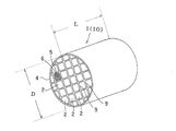
1:ハニカム構造体、2:ハニカムセグメント、4:コーティング材、5:セル、6:隔壁、7:充填材、9:接合材層、10:ハニカムセグメント接合体。 1: honeycomb structure, 2: honeycomb segment, 4: coating material, 5: cell, 6: partition wall, 7: filler, 9: bonding material layer, 10: honeycomb segment bonded body.
以下、本発明を実施の形態に基づいて具体的に説明するが、本発明は以下の実施の形態に限定されるものではなく、本発明の趣旨を逸脱しない範囲で、当業者の通常の知識に基づいて、適宜設計の変更、改良等が加えられることが理解されるべきである。 Hereinafter, the present invention will be described in detail based on embodiments, but the present invention is not limited to the following embodiments, and the general knowledge of those skilled in the art without departing from the spirit of the present invention. Based on the above, it should be understood that design changes, improvements, and the like can be made as appropriate.
図1、2に示すように、本発明の実施の形態におけるハニカム構造体1は、複数のハニカムセグメント2が接合材層9を介して互いの接合面で一体的に接合されたハニカムセグメント接合体10を備え、流体の流路となる複数のセル5が中心軸方向に互いに並行するように配設された構造を有するものであり、接合材層9の外側部分(ハニカムセグメントの接合面との界面からそれぞれ全体の層厚の20%に相当する長さだけ離れた箇所までの部分)における気孔率が、外側部分より内方に位置する中心部分の気孔率よりも小であるとともに、接合材層9のZ軸方向の圧縮ヤング率が5〜100(MPa)であることを特徴とするものである。
As shown in FIGS. 1 and 2, the
まず、本発明の実施の形態におけるハニカム構造体1の構造をさらに具体的に説明する。本発明の実施の形態におけるハニカム構造体1は、多孔質の隔壁6によって区画、形成された流体の流路となる複数のセル5がハニカム構造体1の中心軸方向に互いに並行するように配設された構造を有し、それぞれが全体構造の一部を構成する形状を有するとともに、ハニカム構造体1の中心軸に対して垂直な方向に組み付けられることによって全体構造を構成することになる形状を有する複数のハニカムセグメント2が、接合材層9によって一体的に接合されたハニカムセグメント接合体10として構成されてなるものである。接合材層9によるハニカムセグメント2の接合の後、ハニカム構造体1の中心軸に対して垂直な平面で切断した全体の断面形状が円形、楕円形、三角形、正方形、その他の形状となるように研削加工され、外周面がコーティング材4によって被覆される。このハニカム構造体1をDPFとして用いる場合、ディーゼルエンジンの排気系等に配置することにより、ディーゼルエンジンから排出されるスートを含む粒子状物質(パティキュレート)を捕捉することができる。なお、図1においては、一つのハニカムセグメント2においてのみ、セル5及び隔壁6を示している。それぞれのハニカムセグメント2は、図3、4に示すように、ハニカム構造体1(ハニカムセグメント接合体10)(図1参照)の全体構造の一部を構成する形状を有するとともに、ハニカム構造体1(図1参照)の中心軸に対して垂直な方向に組み付けられることによって全体構造を構成することになる形状を有している。セル5はハニカム構造体1の中心軸方向に互いに並行するように配設されており、隣接しているセル5におけるそれぞれの端部が交互に充填材7によって目封じされている。
First, the structure of the
所定のセル5(流入セル)においては、図3、4における左端部側が開口している一方、右端部側が充填材7によって目封じされており、これと隣接する他のセル5(流出セル)においては、左端部側が充填材7によって目封じされるが、右端部側が開口している。このような目封じにより、図2に示すように、ハニカムセグメント2の端面が市松模様状を呈するようになる。このような複数のハニカムセグメント2が接合されたハニカム構造体1を排ガスの排気系内に配置した場合、排ガスは図4における左側から各ハニカムセグメント2のセル5内に流入して右側に移動する。
In the predetermined cell 5 (inflow cell), the left end side in FIGS. 3 and 4 is open, while the right end side is sealed with the
図4においては、ハニカムセグメント2の左側が排ガスの入口となる場合を示し、排ガスは、目封じされることなく開口しているセル5(流入セル)からハニカムセグメント2内に流入する。セル5(流入セル)に流入した排ガスは、多孔質の隔壁6を通過して他のセル5(流出セル)から流出する。そして、隔壁6を通過する際に排ガス中のスートを含む粒子状物質(パティキュレート)が隔壁6に捕捉される。このようにして、排ガスの浄化を行うことができる。このような捕捉によって、ハニカムセグメント2の内部にはスートを含む粒子状物質(パティキュレート)が経時的に堆積して圧力損失が大きくなるため、スート等を燃焼させる再生が行われる。なお、図2〜4には、全体の断面形状が正方形のハニカムセグメント2を示すが、三角形、六角形等の形状であってもよい。また、セル5の断面形状も、三角形、六角形、円形、楕円形、その他の形状であってもよい。
FIG. 4 shows a case where the left side of the
本発明のハニカム構造体は、上述の構造を有するものであり、接合材層9の外側部分(ハニカムセグメントの接合面との界面からそれぞれ全体の層厚の20%に相当する長さだけ離れた箇所までの部分)における気孔率が、外側部分より内方に位置する中心部分の気孔率よりも小であるとともに、接合材層9は、そのZ軸方向の圧縮ヤング率が5〜100(MPa)、好ましくは、Z軸方向の圧縮ヤング率が10〜80(MPa)、さらに好ましくは、Z軸方向の圧縮ヤング率が15〜50(MPa)である。
The honeycomb structure of the present invention has the above-described structure, and is separated from the outer portion of the bonding material layer 9 (a length corresponding to 20% of the entire layer thickness from the interface with the bonding surface of the honeycomb segment). The porosity of the portion up to the portion) is smaller than the porosity of the central portion located inward from the outer portion, and the
Z軸方向の圧縮ヤング率は、次のように算出した。所定の寸法(10×10mm〜30×30mm、厚み0.5〜3mm)の試料を切り出し、Z軸方向の圧縮試験を行った。尚、試料には基材がついていてもかまわない。Z軸方向の圧縮ヤング率は、荷重を0〜3MPaまで試料に加えた時の応力−ひずみ曲線における傾きをヤング率として、下式より算出した。 The compressive Young's modulus in the Z-axis direction was calculated as follows. Samples having predetermined dimensions (10 × 10 mm to 30 × 30 mm, thickness 0.5 to 3 mm) were cut out and subjected to a compression test in the Z-axis direction. The sample may have a base material. The compressive Young's modulus in the Z-axis direction was calculated from the following equation using the slope in the stress-strain curve when the load was applied to the sample from 0 to 3 MPa as the Young's modulus.

W : 荷重(N)
S : 試料面積(mm2)
t : 試料厚み(mm)
Δt : 試料厚みの変化量(mm)
W: Load (N)
S: Sample area (mm 2 )
t: Sample thickness (mm)
Δt: Sample thickness change (mm)
本実施の形態に用いられる接合材層の外側部分(ハニカムセグメントの接合面との界面からそれぞれ全体の層厚の20%に相当する長さだけ離れた箇所までの部分)における気孔率が、外側部分より内方に位置する中心部分の気孔率以上であると、外側部分ではセグメント/接合材層界面の接合強度を確保することができず、中心部分の気孔率により接合材層のヤング率を低くすることができず、セグメント/接合材層界面の接合強度確保と接合材層の応力緩和機能との両立が不可能となる。 The porosity in the outer portion of the bonding material layer used in the present embodiment (the portion from the interface with the bonding surface of the honeycomb segment to a portion separated by a length corresponding to 20% of the total layer thickness) is outside. If the porosity is greater than or equal to the porosity of the central portion located inward from the portion, the bonding strength at the segment / bonding material layer interface cannot be secured in the outer portion, and the Young's modulus of the bonding material layer is increased by the porosity of the central portion. It cannot be lowered, and it is impossible to achieve both the joining strength at the segment / bonding material layer interface and the stress relaxation function of the bonding material layer.
本実施の形態に用いられる接合材層のZ軸方向の圧縮ヤング率が、5MPa未満であると、セグメント中に温度分布を持ったときに、セグメント自体の変形が大きくなってクラックが発生し、一方100MPaより大きくなると、セグメント単体では問題ないが、複数のハニカムセグメトが接合材層で一体化ハニカム構造体において、応力が緩和できず、DPFでの再生時に生じる急激な熱応力により外周部が破損することがある。 When the compressive Young's modulus in the Z-axis direction of the bonding material layer used in the present embodiment is less than 5 MPa, when the segment has a temperature distribution, deformation of the segment itself increases and cracks occur. On the other hand, if it exceeds 100 MPa, there is no problem with a single segment, but in the honeycomb structure in which a plurality of honeycomb segments are formed of a bonding material layer, the stress cannot be relieved, and the outer peripheral portion is caused by a rapid thermal stress generated during regeneration with a DPF. It may be damaged.
本実施の形態に用いられる接合材層の外側部分の気孔率が5〜40%であり、かつ中心部分の気孔率が25〜90%であることが好ましい。接合材層9の外側部分の気孔率が10〜30%であり、かつ中心部分の気孔率が30〜70%であることがさらに好ましい。外側部分の気孔率が5%未満であると、ヤング率が大きくなり応力緩和機能を十分に発揮することができないことがあり、40%を超えると、セグメント/接合材層の接合強度が低減することがある。また、中心部分の気孔率が25%未満であると、ヤング率が大きくなり、90%を超えると、強度が低減し、クラックが発生することがある。接合材層部分の平均気孔率は17〜70%で、更に好ましくは22〜54%である。
It is preferable that the porosity of the outer portion of the bonding material layer used in the present embodiment is 5 to 40%, and the porosity of the central portion is 25 to 90%. More preferably, the porosity of the outer portion of the
本実施の形態に用いられるハニカム構造体は、その長さLと直径Dの比(L/D)がL/D<4.0の関係を満たすことが好ましく、L/D<2.5の関係を満たすことがさらに好ましく、L/D<1.5の関係を満たすことが特に好ましい。長さLと直径Dの比(L/D)が4.0以上であるとDPFでの再生時に生じる中心部と端部の温度差が大きくなり、急激な熱応力により破損することがある。ここで、直径Dは、ハニカム構造体の断面形状が円形の場合はその直径、楕円形状の場合は短軸及び長軸の平均値、その他の形状の場合は外接円の直径で定義される。 In the honeycomb structure used in the present embodiment, the ratio of the length L to the diameter D (L / D) preferably satisfies the relationship of L / D <4.0, and L / D <2.5. It is more preferable to satisfy the relationship, and it is particularly preferable to satisfy the relationship of L / D <1.5. If the ratio of the length L to the diameter D (L / D) is 4.0 or more, the temperature difference between the center portion and the end portion that occurs during regeneration with the DPF increases, and damage may occur due to rapid thermal stress. Here, the diameter D is defined by the diameter when the cross-sectional shape of the honeycomb structure is circular, the average value of the minor axis and the major axis in the case of an elliptical shape, and the diameter of the circumscribed circle in the case of other shapes.
また、本実施の形態に用いられる接合材層には、無機繊維が含有されるが、これ以外に、例えば、無機バインダー、有機バインダー、無機粒子、発泡粒子等が含有されることが好ましい。無機繊維としては、例えば、アルミノシリケート、アルミナ、SiO2−MgO系及びSiO2−CaO−MgO系等の酸化物繊維、その他の繊維(例えば、SiC繊維)等を挙げることができる。無機バインダーとしては、例えば、シリカゾル、アルミナゾル、粘土等を挙げることができる。有機バインダーとしては、例えば、ポリビニルアルコール(PVA)、カルボキシメチルセルローズ(CMC)、メチルセルロース(MC)等を挙げることができる。無機粒子としては、例えば、炭化珪素、窒化珪素、コージェライト、アルミナ、ムライト等のセラミックスを挙げることができる。なお、接合材層を構成する接合材は、後述するコーティング材と同じ材料を用いることができる。In addition, the bonding material layer used in the present embodiment contains inorganic fibers, but in addition to this, for example, it is preferable that an inorganic binder, an organic binder, inorganic particles, expanded particles, and the like are contained. Examples of the inorganic fiber include oxide fibers such as aluminosilicate, alumina, SiO 2 —MgO and SiO 2 —CaO—MgO, and other fibers (for example, SiC fibers). Examples of the inorganic binder include silica sol, alumina sol, clay and the like. Examples of the organic binder include polyvinyl alcohol (PVA), carboxymethyl cellulose (CMC), methyl cellulose (MC), and the like. Examples of the inorganic particles include ceramics such as silicon carbide, silicon nitride, cordierite, alumina, and mullite. In addition, the same material as the coating material mentioned later can be used for the joining material which comprises a joining material layer.
無機繊維の含有率は20〜45質量%(さらに好ましくは30〜40質量%)、ショット含有率が10〜50質量%、長軸方向に垂直な断面における平均直径値が1〜20μm(さらに好ましくは2〜15μm)及び長軸方向の平均長さが10〜600μm(さらに好ましくは50〜300μm)であることが好ましい。 The content of the inorganic fiber is 20 to 45% by mass (more preferably 30 to 40% by mass), the shot content is 10 to 50% by mass, and the average diameter value in the cross section perpendicular to the major axis direction is 1 to 20 μm (more preferably 2 to 15 μm) and the average length in the major axis direction is preferably 10 to 600 μm (more preferably 50 to 300 μm).
無機繊維の含有率が20質量%未満であると、接合材層に弾力性を付与できないことがあり、45質量%を超えると、塗布可能なペーストを得るために大量の水を必要とし、大量の水の使用は、接合材乾燥時の収縮が大きく、クラックが起きることがある。ショット含有率が10質量%未満であると、塗布可能なペーストを得るために大量の水を必要とし、大量の水の使用は、接合材乾燥時の収縮が大きく、クラックが起きることがあり、50質量%を超えると、接合材層に弾力性を付与できないことがある。長軸方向に垂直な断面における平均直径値が1μm未満であると、接合材層に弾力性を付与できないことがあり、20μmを超えると、接合材の厚みに与える影響が大きいため、ハニカムセグメントの外壁面上に均一に塗布することが困難となることがある。長軸方向の平均長さが10μm未満であると、接合材層に弾力性を付与できないことがあり、600μmを超えると、塗布生が低下することがある。 If the content of the inorganic fiber is less than 20% by mass, elasticity may not be imparted to the bonding material layer. If the content exceeds 45% by mass, a large amount of water is required to obtain a paste that can be applied. The use of water causes a large shrinkage when the bonding material is dried and may cause cracks. When the shot content is less than 10% by mass, a large amount of water is required to obtain a paste that can be applied, and the use of a large amount of water causes a large shrinkage when drying the bonding material, and may cause cracks. If it exceeds 50% by mass, elasticity may not be imparted to the bonding material layer. If the average diameter value in the cross section perpendicular to the major axis direction is less than 1 μm, the bonding material layer may not be given elasticity, and if it exceeds 20 μm, the thickness of the bonding material is greatly affected. It may be difficult to apply uniformly on the outer wall surface. If the average length in the major axis direction is less than 10 μm, elasticity may not be imparted to the bonding material layer, and if it exceeds 600 μm, the coating strength may decrease.
図2に示すように、接合材層9は、ハニカムセグメント2の外周面に塗布されて、ハニカムセグメント2を接合するように機能する。接合材層9の塗布は、隣接しているそれぞれのハニカムセグメント2の外周面に行ってもよいが、隣接したハニカムセグメント2の相互間においては、対応した外周面の一方に対してだけ行ってもよい。このような対応面の片側だけへの塗布は、接合材層9の使用量を節約できる点で好ましい。接合材層9の厚さは、ハニカムセグメント2の相互間の接合力を勘案して決定され、例えば、0.5〜3.0mmの範囲で適宜選択される。
As shown in FIG. 2, the
本実施の形態に用いられるハニカムセグメント2の材料としては、強度、耐熱性の観点から、炭化珪素(SiC)、炭化珪素(SiC)を骨材としてかつ珪素(Si)を結合材として形成された珪素−炭化珪素系複合材料、窒化珪素、コージェライト、ムライト、アルミナ、スピネル、炭化珪素−コージェライト系複合材、珪素−炭化珪素複合材、リチウムアルミニウムシリケート、チタン酸アルミニウム、Fe−Cr−Al系金属からなる群から選択される少なくとも一種から構成された物を挙げることができる。中でも、炭化珪素(SiC)又は珪素−炭化珪素系複合材料から構成されてなるものが好ましい。
As a material of the
ハニカムセグメント2の作製は、例えば、上述の材料から適宜選択したものに、メチルセルロース、ヒドロキシプロポキシルセルロース、ヒドロキシエチルセルロース、カルボキシメチルセルロース、ポリビニルアルコール等のバインダー、界面活性剤、溶媒としての水等を添加して、可塑性の坏土とし、この坏土を上述の形状となるように押出成形し、次いで、マイクロ波、熱風等によって乾燥した後、焼結することにより行うことができる。
For example, the
セル5の目封じに用いる充填材7としては、ハニカムセグメント2と同様な材料を用いることができる。充填材7による目封じは、目封じをしないセル5をマスキングした状態で、ハニカムセグメント2の端面をスラリー状の充填材7に浸漬することにより開口しているセル5に充填することにより行うことができる。充填材7の充填は、ハニカムセグメント2の成形後における焼成前に行っても、焼成後に行ってもよいが、焼成前に行うことの方が、焼成工程が1回で終了するため好ましい。
As the
以上のようなハニカムセグメント2の作製の後、ハニカムセグメント2の外周面にスラリー状の接合材層9を塗布し、所定の立体形状(ハニカム構造体1の全体構造)となるように複数のハニカムセグメント2を組み付け、この組み付けた状態で圧着した後、加熱乾燥する。このようにして、複数のハニカムセグメント2が一体的に接合された接合体が作製される。その後、この接合体を上述の形状に研削加工し、外周面をコーティング材4によって被覆し、加熱乾燥する。このようにして、図1に示すハニカム構造体1が作製される。コーティング材4の材質としては、接合材層9と同様の用いられるのを用いることができる。コーティング材4の厚さは、例えば、0.1〜1.5mmの範囲で適宜選択される。
After manufacturing the
以上説明したように、本発明によって、排ガス用の捕集フィルタ、中でも、ディーゼルエンジンの排ガス中の粒子状物質(パティキュレート)等を捕集するディーゼルパティキュレートフィルタ(DPF)として有用な、耐熱衝撃性に優れ、特にフィルタ再生時におけるクラック等の欠陥の発生が確実に抑制されたハニカム構造体が提供される。 As described above, according to the present invention, a thermal shock that is useful as a collection filter for exhaust gas, particularly a diesel particulate filter (DPF) that collects particulate matter (particulate) in exhaust gas of a diesel engine. Provided is a honeycomb structure that is excellent in performance and in which the occurrence of defects such as cracks during filter regeneration is reliably suppressed.
以下、本発明を実施例によってさらに具体的に説明するが、本発明は、これらの実施例によっていかなる制限を受けるものではない。 Hereinafter, the present invention will be described more specifically with reference to examples. However, the present invention is not limited to these examples.
(実施例1)(ハニカムセグメントの作製)ハニカムセグメント原料として、SiC粉末及び金属Si粉末を80:20の質量割合で混合し、これに造孔剤として澱粉、発泡樹脂を加え、さらにメチルセルロース及びヒドロキシプロポキシルメチルセルロース、界面活性剤及び水を添加して、可塑性の坏土を作製した。この坏土を押出成形し、マイクロ波及び熱風で乾燥して隔壁の厚さが310μm、セル密度が約46.5セル/cm2(300セル/平方インチ)、断面が一辺35mmの正四角形、長さが152mmのハニカムセグメント成形体を得た。このハニカムセグメント成形体を、端面が市松模様状を呈するように、セルの両端面を目封じした。すなわち、隣接するセルが、互いに反対側の端部で封じられるように目封じを行った。目封じ材としては、ハニカムセグメント原料と同様な材料を用いた。セルの両端面を目封じし、乾燥させた後、大気雰囲気中約400℃で脱脂し、その後、Ar不活性雰囲気で約1450℃で焼成して、SiC結晶粒子をSiで結合させた、多孔質構造を有するハニカムセグメントを得た。(Example 1) (Preparation of honeycomb segment) As a honeycomb segment raw material, SiC powder and metal Si powder are mixed at a mass ratio of 80:20, starch and foamed resin are added as a pore-forming agent, and methylcellulose and hydroxy are further added. Propoxyl methylcellulose, surfactant and water were added to make a plastic clay. This clay is extruded and dried with microwaves and hot air to form a square having a partition wall thickness of 310 μm, a cell density of about 46.5 cells / cm 2 (300 cells / square inch), and a cross section of 35 mm on a side, A honeycomb segment formed body having a length of 152 mm was obtained. In this honeycomb segment molded body, both end faces of the cells were sealed so that the end faces had a checkered pattern. That is, the sealing was performed so that adjacent cells were sealed at opposite ends. As the plugging material, the same material as the honeycomb segment material was used. After sealing both ends of the cell and drying, degreasing at about 400 ° C. in an air atmosphere, and then baking at about 1450 ° C. in an Ar inert atmosphere to bond SiC crystal particles with Si. A honeycomb segment having a quality structure was obtained.
(接合材の調製)無機繊維としてアルミノシリケート繊維を用い、ショット率は全て50%であった。無機バインダーとしてコロイダルシリカを22質量%及び粘土を1質量%、無機粒子としてSiCを混合したものにさらに水を加えて、場合によっては、有機バインダー(CMC、PVA)、発泡樹脂及び分散剤を加えて、ミキサーにて30分間混練を行い、ペースト状の接合材を得た。具体的には、表1に示す条件で、種類及び組成比の異なる接合材(接合材No.1〜12)を得た。 (Preparation of bonding material) Aluminosilicate fibers were used as inorganic fibers, and the shot ratios were all 50%. Water is added to 22% by mass of colloidal silica and 1% by mass of clay as an inorganic binder, and SiC is mixed as inorganic particles. In some cases, an organic binder (CMC, PVA), a foamed resin and a dispersant are added. Then, the mixture was kneaded for 30 minutes to obtain a paste-like bonding material. Specifically, joining materials (joining materials No. 1 to 12) having different types and composition ratios were obtained under the conditions shown in Table 1.
(ハニカム構造体の作製)ハニカムセグメントの外壁面に、厚さ約1mmとなるように接合材No.1をコーティングして接合材層を形成し、その上に別のハニカムセグメントを載置する工程を繰り返し、16個のハニカムセグメントからなるハニカムセグメント積層体を作製し、外部より圧力を加え、全体を接合させた後、140℃、2時間乾燥してハニカムセグメント接合体を得た。その後、ハニカムセグメント接合体の外周を円筒状に切断後、コーティング材を塗布し、700℃、2時間乾燥硬化させ、ハニカム構造体を得た。得られたハニカム構造体を切断して所定の気孔率測定用サンプルを切り出し、樹脂埋め、研磨後、気孔率測定用サンプルの断面における気孔の分布状況をSEMにて10〜40倍程度で観察した。得られた写真の画像解析(Media Cybernetics社製、ImagePro(Ver5.0))から気孔率を測定した。気孔の分布状況を観察した結果を図5に示す。気孔率を算出するにあたり、少なくとも試料長さ3mm以上の領域を用いた。結果を表2に示す。接合材中心部分の気孔率は68%で、外側部分の気孔率は37%であった。 (Preparation of honeycomb structure) On the outer wall surface of the honeycomb segment, the bonding material No. 1 was formed so as to have a thickness of about 1 mm. 1 is applied to form a bonding material layer, and another honeycomb segment is placed thereon to produce a honeycomb segment laminated body composed of 16 honeycomb segments. After bonding, the honeycomb segment bonded body was obtained by drying at 140 ° C. for 2 hours. Then, after the outer periphery of the joined honeycomb segment assembly was cut into a cylindrical shape, a coating material was applied and dried and cured at 700 ° C. for 2 hours to obtain a honeycomb structure. The obtained honeycomb structure was cut to cut out a predetermined porosity measurement sample, filled with resin, and polished, and then the distribution of pores in the cross section of the porosity measurement sample was observed with a SEM at about 10 to 40 times. . The porosity was measured by image analysis of the obtained photograph (MediaPro (Ver. 5.0), manufactured by Media Cybernetics). The result of observing the distribution of pores is shown in FIG. In calculating the porosity, at least a region having a sample length of 3 mm or more was used. The results are shown in Table 2. The porosity of the central part of the bonding material was 68%, and the porosity of the outer part was 37%.
接合材Z軸方向の圧縮ヤング率の結果を表2に示す。接合材のZ軸方向の圧縮ヤング率は95MPaであった。 Table 2 shows the results of the compressive Young's modulus in the bonding material Z-axis direction. The compressive Young's modulus in the Z-axis direction of the bonding material was 95 MPa.
さらに、得られたハニカム構造体の急速加熱試験(バーナースポーリング試験B−sp)、急速冷却試験(電気炉スポーリング試験E−sp)、エンジン試験(E/G試験)を行った。結果を表2に示す。 Further, a rapid heating test (burner spalling test B-sp), a rapid cooling test (electric furnace spalling test E-sp), and an engine test (E / G test) were performed on the obtained honeycomb structure. The results are shown in Table 2.
(実施例2〜9および比較例1〜3)実施例2〜9は、実施例1において、接合材を、接合材No.2〜9に変えたこと以外は実施例1と同様にした。また、比較例1〜3は、接合材No.10〜12に変えたこと以外は実施例1と同様にした。各実施例及び比較例における、ハニカム構造体の接合材の各種試験結果を表2に示す。 (Examples 2 to 9 and Comparative Examples 1 to 3) Examples 2 to 9 are the same as those in Example 1 except that the bonding material is a bonding material No. The procedure was the same as in Example 1 except that the values were changed to 2-9. In Comparative Examples 1 to 3, the bonding material No. The procedure was the same as Example 1 except that the number was changed to 10-12. Table 2 shows various test results of the bonding material of the honeycomb structure in each example and comparative example.
「B−sp」試験:バーナースポーリング試験(急速加熱試験):ハニカム構造体にバーナーで加熱した空気を流すことにより中心部分と外側部分との温度差をつくり、ハニカム構造体のクラックの発生しない温度により耐熱衝撃性を評価する試験(温度が高いほど耐熱衝撃性が高い) "B-sp" test: Burner spalling test (rapid heating test): A temperature difference between the central portion and the outer portion is created by flowing air heated by a burner through the honeycomb structure, and cracks in the honeycomb structure do not occur Test to evaluate thermal shock resistance by temperature (The higher the temperature, the higher the thermal shock resistance)
「E−sp」試験:電気炉スポーリング試験(急速冷却試験):ハニカム構造体を電気炉にて500℃×2h加熱し、均一な温度にした後、室温に取り出し、ハニカム構造体のクラック発生の有無により耐熱衝撃性を評価する試験 “E-sp” test: Electric furnace spalling test (rapid cooling test): The honeycomb structure was heated in an electric furnace at 500 ° C. for 2 hours, brought to a uniform temperature, taken out to room temperature, and cracks occurred in the honeycomb structure Test to evaluate thermal shock resistance by the presence or absence of
「E/G」試験:エンジン試験1000℃:フィルタ再生のために堆積したパーティキュレートを燃焼させ、ハニカム中心止部の温度が1000℃となる条件にて、ハニカム構造体のクラックの有無により耐熱衝撃性を評価する試験 “E / G” test: engine test 1000 ° C .: thermal shock caused by the presence or absence of cracks in the honeycomb structure under the condition that the particulate deposited for filter regeneration is burned and the temperature at the center of the honeycomb is 1000 ° C. Test to evaluate sex
表2中、○はクラック発生なし、×はクラック発生ありを意味する。表2の結果から分かるように、接合材層のZ軸の圧縮ヤング率の値が150MPaである接合材No.10(比較例1)や、接合材層のZ軸の圧縮ヤング率の値が105MPaでかつ接合材層の中心部分の気孔率が、外側部分の接合材の気孔率より小さい構造であるNo.11(比較例2)は、各種試験後、ハニカム構造体にクラックが発生した。更に、接合材層のZ軸の圧縮ヤング率の値が4MPaでかつ接合材層の中心部分の気孔率が、外側部分の接合材の気孔率より小さい構造であるNo.12(比較例3)は、各種試験後、ハニカム構造体にクラックが発生した。接合材層が十分な弾性力を発揮できず、試験中に発生する熱応力を緩和できなかったものと考えられる。一方、接合材層のZ軸方向のヤング率の値が5〜100MPaの範囲内にあり、かつ、接合材層の中心部分の気孔率が外側部分の接合材層の気孔率より大きい構造である接合材No.1〜9(実施例1〜9)は、各種試験後、ハニカム構造体にクラックは見られなかった。 In Table 2, “O” means no occurrence of cracks, and “X” means occurrence of cracks. As can be seen from the results of Table 2, the bonding material No. No. 10 (Comparative Example 1), No. 10 having a structure in which the Z-axis compressive Young's modulus value of the bonding material layer is 105 MPa, and the porosity of the central portion of the bonding material layer is smaller than the porosity of the bonding material of the outer portion. In No. 11 (Comparative Example 2), cracks occurred in the honeycomb structure after various tests. Furthermore, the value of the compressive Young's modulus of the Z-axis of the bonding material layer is 4 MPa, and the porosity of the central portion of the bonding material layer is smaller than the porosity of the bonding material of the outer portion. In No. 12 (Comparative Example 3), cracks occurred in the honeycomb structure after various tests. It is considered that the bonding material layer could not exhibit sufficient elastic force and could not relax the thermal stress generated during the test. On the other hand, the value of the Young's modulus in the Z-axis direction of the bonding material layer is in the range of 5 to 100 MPa, and the porosity of the central portion of the bonding material layer is larger than the porosity of the bonding material layer of the outer portion. Bonding material No. In Nos. 1 to 9 (Examples 1 to 9), no cracks were observed in the honeycomb structure after various tests.
本発明のハニカム構造体は、排ガス用の捕集フィルタとして、例えば、ディーゼルエンジン等からの排ガスに含まれている粒子状物質(パティキュレート)を捕捉して除去するためのディーゼルパティキュレートフィルタ(DPF)として有用である。 The honeycomb structure of the present invention is a diesel particulate filter (DPF) for capturing and removing particulate matter (particulates) contained in exhaust gas from a diesel engine or the like, for example, as a collection filter for exhaust gas. ) Is useful.
Claims (11)
前記接合材層の外側部分(ハニカムセグメントの接合面との界面からそれぞれ全体の層厚の20%に相当する長さだけ離れた箇所までの部分)における気孔率が、外側部分より内方に位置する中心部分の気孔率よりも小であるとともに、
前記接合材層のZ軸方向の圧縮ヤング率が5〜100(MPa)であるハニカム構造体。A honeycomb segment bonded body in which a plurality of honeycomb segments are integrally bonded to each other through a bonding material layer, and a plurality of cells serving as fluid flow paths are arranged in parallel to each other in the central axis direction. A honeycomb structure having a structured structure,
The porosity in the outer portion of the bonding material layer (the portion up to a distance corresponding to 20% of the total layer thickness from the interface with the bonding surface of the honeycomb segments) is located inward from the outer portion. And smaller than the porosity of the central part
A honeycomb structure having a compressive Young's modulus in the Z-axis direction of the bonding material layer of 5 to 100 (MPa).
Priority Applications (1)
| Application Number | Priority Date | Filing Date | Title |
|---|---|---|---|
| JP2008507480A JP5103378B2 (en) | 2006-03-23 | 2007-03-23 | Honeycomb structure |
Applications Claiming Priority (4)
| Application Number | Priority Date | Filing Date | Title |
|---|---|---|---|
| JP2006081795 | 2006-03-23 | ||
| JP2006081795 | 2006-03-23 | ||
| JP2008507480A JP5103378B2 (en) | 2006-03-23 | 2007-03-23 | Honeycomb structure |
| PCT/JP2007/056107 WO2007111280A1 (en) | 2006-03-23 | 2007-03-23 | Honeycomb structure |
Publications (2)
| Publication Number | Publication Date |
|---|---|
| JPWO2007111280A1 true JPWO2007111280A1 (en) | 2009-08-13 |
| JP5103378B2 JP5103378B2 (en) | 2012-12-19 |
Family
ID=38541197
Family Applications (1)
| Application Number | Title | Priority Date | Filing Date |
|---|---|---|---|
| JP2008507480A Active JP5103378B2 (en) | 2006-03-23 | 2007-03-23 | Honeycomb structure |
Country Status (5)
| Country | Link |
|---|---|
| US (1) | US8053054B2 (en) |
| EP (1) | EP1997790A4 (en) |
| JP (1) | JP5103378B2 (en) |
| KR (1) | KR20090004935A (en) |
| WO (1) | WO2007111280A1 (en) |
Families Citing this family (11)
| Publication number | Priority date | Publication date | Assignee | Title |
|---|---|---|---|---|
| WO2008155856A1 (en) * | 2007-06-21 | 2008-12-24 | Ibiden Co., Ltd. | Honeycomb structure and process for producing the same |
| WO2009141897A1 (en) * | 2008-05-20 | 2009-11-26 | イビデン株式会社 | Honeycomb structure |
| BRPI1010158A2 (en) * | 2009-06-29 | 2016-03-29 | Dow Global Technologies Inc | method for forming a honeycomb structure, ceramic honeycomb structure and cement composition |
| KR20120095960A (en) * | 2009-11-11 | 2012-08-29 | 다우 글로벌 테크놀로지스 엘엘씨 | Improved cement to make thermal shock resistant ceramic honeycomb structures and method to make them |
| JP6043286B2 (en) * | 2012-02-24 | 2016-12-14 | 日本碍子株式会社 | Honeycomb structure |
| JP5844672B2 (en) | 2012-03-28 | 2016-01-20 | 日本碍子株式会社 | Honeycomb structure |
| WO2016153955A1 (en) * | 2015-03-23 | 2016-09-29 | Corning Incorporated | Exhaust gas treatment article and methods of manufacturing same |
| TWI579480B (en) * | 2016-05-19 | 2017-04-21 | 富利康科技股份有限公司 | Method for strengthening ceramic fiber filter tube and strengthened ceramic fiber filter tube |
| EP3505244B1 (en) * | 2016-08-26 | 2021-09-22 | N.E. Chemcat Corporation | Honeycomb structure, honeycomb structure type catalyst, and production methods therefor |
| JP6693477B2 (en) * | 2017-06-13 | 2020-05-13 | 株式会社デンソー | Exhaust gas purification filter |
| JP2023172124A (en) * | 2022-05-23 | 2023-12-06 | 株式会社リコー | Ceramic structure and its manufacturing method |
Family Cites Families (5)
| Publication number | Priority date | Publication date | Assignee | Title |
|---|---|---|---|---|
| JP3121497B2 (en) | 1994-07-14 | 2000-12-25 | イビデン株式会社 | Ceramic structure |
| US5914187A (en) * | 1996-01-12 | 1999-06-22 | Ibiden Co., Ltd. | Ceramic structural body |
| JPWO2005089901A1 (en) * | 2004-03-23 | 2008-01-31 | 日本碍子株式会社 | Honeycomb structure and manufacturing method thereof |
| EP1860082B1 (en) * | 2005-03-16 | 2019-10-09 | NGK Insulators, Ltd. | Honeycomb structure |
| WO2007083711A1 (en) * | 2006-01-18 | 2007-07-26 | Ngk Insulators, Ltd. | Honeycomb structure |
-
2007
- 2007-03-23 KR KR1020087024747A patent/KR20090004935A/en not_active Ceased
- 2007-03-23 EP EP07739548A patent/EP1997790A4/en not_active Withdrawn
- 2007-03-23 WO PCT/JP2007/056107 patent/WO2007111280A1/en not_active Ceased
- 2007-03-23 JP JP2008507480A patent/JP5103378B2/en active Active
-
2008
- 2008-09-18 US US12/233,321 patent/US8053054B2/en active Active
Also Published As
| Publication number | Publication date |
|---|---|
| US20090029104A1 (en) | 2009-01-29 |
| JP5103378B2 (en) | 2012-12-19 |
| EP1997790A1 (en) | 2008-12-03 |
| US8053054B2 (en) | 2011-11-08 |
| WO2007111280A1 (en) | 2007-10-04 |
| KR20090004935A (en) | 2009-01-12 |
| EP1997790A4 (en) | 2010-04-28 |
Similar Documents
| Publication | Publication Date | Title |
|---|---|---|
| JP5103378B2 (en) | Honeycomb structure | |
| JP5485546B2 (en) | Bonded body, honeycomb segment bonded body, and honeycomb structure using the same | |
| JP5367363B2 (en) | Bonded body, bonded material composition, honeycomb segment bonded body, and honeycomb structure using the same | |
| JP5209315B2 (en) | Honeycomb filter | |
| JP5524924B2 (en) | Honeycomb structure | |
| US7473456B2 (en) | Honeycomb structure | |
| JP5469305B2 (en) | Bonding material, manufacturing method thereof, and honeycomb structure using the same | |
| JP4890857B2 (en) | Honeycomb structure | |
| JP4927710B2 (en) | Honeycomb structure | |
| JP4997068B2 (en) | JOINT BODY AND MANUFACTURING METHOD THEREOF | |
| JP4997064B2 (en) | Bonding material composition and method for producing the same, joined body and method for producing the same | |
| JP4434076B2 (en) | Honeycomb structure | |
| JP4607689B2 (en) | Honeycomb structure | |
| JP2003275522A (en) | Ceramic filter assembly | |
| JP5313878B2 (en) | Honeycomb structure using honeycomb segment | |
| JP4616752B2 (en) | Honeycomb structure | |
| JP2010235338A (en) | Bonded honeycomb segment assembly | |
| JP2007252993A (en) | Honeycomb structure | |
| JPWO2008126485A1 (en) | JOINT BODY, MANUFACTURING METHOD THEREOF, JOINT MATERIAL COMPOSITION, AND ITS MANUFACTURING METHOD | |
| JPWO2008096569A1 (en) | DPF honeycomb segment bonded body and bonded material composition for bonded body |
Legal Events
| Date | Code | Title | Description |
|---|---|---|---|
| A621 | Written request for application examination |
Free format text: JAPANESE INTERMEDIATE CODE: A621 Effective date: 20091119 |
|
| A131 | Notification of reasons for refusal |
Free format text: JAPANESE INTERMEDIATE CODE: A131 Effective date: 20120710 |
|
| A521 | Request for written amendment filed |
Free format text: JAPANESE INTERMEDIATE CODE: A523 Effective date: 20120831 |
|
| TRDD | Decision of grant or rejection written | ||
| A01 | Written decision to grant a patent or to grant a registration (utility model) |
Free format text: JAPANESE INTERMEDIATE CODE: A01 Effective date: 20120925 |
|
| A01 | Written decision to grant a patent or to grant a registration (utility model) |
Free format text: JAPANESE INTERMEDIATE CODE: A01 |
|
| A61 | First payment of annual fees (during grant procedure) |
Free format text: JAPANESE INTERMEDIATE CODE: A61 Effective date: 20121001 |
|
| FPAY | Renewal fee payment (event date is renewal date of database) |
Free format text: PAYMENT UNTIL: 20151005 Year of fee payment: 3 |
|
| R150 | Certificate of patent or registration of utility model |
Ref document number: 5103378 Country of ref document: JP Free format text: JAPANESE INTERMEDIATE CODE: R150 Free format text: JAPANESE INTERMEDIATE CODE: R150 |