JPWO2007097394A1 - Waterproof structure of connector housing - Google Patents
Waterproof structure of connector housing Download PDFInfo
- Publication number
- JPWO2007097394A1 JPWO2007097394A1 JP2008501752A JP2008501752A JPWO2007097394A1 JP WO2007097394 A1 JPWO2007097394 A1 JP WO2007097394A1 JP 2008501752 A JP2008501752 A JP 2008501752A JP 2008501752 A JP2008501752 A JP 2008501752A JP WO2007097394 A1 JPWO2007097394 A1 JP WO2007097394A1
- Authority
- JP
- Japan
- Prior art keywords
- terminal
- connector housing
- waterproof
- seal material
- housing
- Prior art date
- Legal status (The legal status is an assumption and is not a legal conclusion. Google has not performed a legal analysis and makes no representation as to the accuracy of the status listed.)
- Pending
Links
- 239000000463 material Substances 0.000 claims abstract description 26
- 239000003566 sealing material Substances 0.000 claims description 10
- 230000037431 insertion Effects 0.000 claims description 3
- 238000003780 insertion Methods 0.000 claims description 3
- 238000010276 construction Methods 0.000 claims 1
- 230000001105 regulatory effect Effects 0.000 claims 1
- 230000004308 accommodation Effects 0.000 abstract description 3
- XLYOFNOQVPJJNP-UHFFFAOYSA-N water Substances O XLYOFNOQVPJJNP-UHFFFAOYSA-N 0.000 abstract description 3
- 238000007789 sealing Methods 0.000 abstract description 2
- 210000000078 claw Anatomy 0.000 description 4
- 230000013011 mating Effects 0.000 description 2
- 229920003051 synthetic elastomer Polymers 0.000 description 2
- 239000005061 synthetic rubber Substances 0.000 description 2
- 229920000106 Liquid crystal polymer Polymers 0.000 description 1
- 239000004977 Liquid-crystal polymers (LCPs) Substances 0.000 description 1
- 238000002788 crimping Methods 0.000 description 1
- 230000010354 integration Effects 0.000 description 1
- 229920002379 silicone rubber Polymers 0.000 description 1
- 229920003002 synthetic resin Polymers 0.000 description 1
- 239000000057 synthetic resin Substances 0.000 description 1
- 238000004078 waterproofing Methods 0.000 description 1
Images


Classifications
-
- H—ELECTRICITY
- H01—ELECTRIC ELEMENTS
- H01R—ELECTRICALLY-CONDUCTIVE CONNECTIONS; STRUCTURAL ASSOCIATIONS OF A PLURALITY OF MUTUALLY-INSULATED ELECTRICAL CONNECTING ELEMENTS; COUPLING DEVICES; CURRENT COLLECTORS
- H01R13/00—Details of coupling devices of the kinds covered by groups H01R12/70 or H01R24/00 - H01R33/00
- H01R13/46—Bases; Cases
- H01R13/52—Dustproof, splashproof, drip-proof, waterproof, or flameproof cases
- H01R13/5205—Sealing means between cable and housing, e.g. grommet
Landscapes
- Connector Housings Or Holding Contact Members (AREA)
Abstract
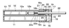
端子の小型化に合わせて、コネクタハウジングを小型化する。電線22、防水シール材23を取り付けた接続端子12を入口部14から端子収容孔11内に挿入すると、防水シール材23の段部24が入口部14の段部15と衝合すると共に、テーパ面26がテーパ面16と合致して、端子収容孔11中には後方から水が浸入することがなくなる。この状態において、リアホルダ17により防水シール材23をハウジング10に向けて押圧すると、防水シール材23が外れることを防止する。このように、防水シール材23の一部をハウジング10の外側に配置しながら、入口部14を封止することにより、端子収容孔11の横幅、縦幅を実質的に接続端子12が通過し得る大きさとすることができる。The connector housing is miniaturized in accordance with the miniaturization of terminals. When the connection terminal 12 to which the electric wire 22 and the waterproof seal material 23 are attached is inserted into the terminal accommodating hole 11 from the inlet portion 14, the step portion 24 of the waterproof seal material 23 abuts on the step portion 15 of the inlet portion 14 and is tapered. The surface 26 coincides with the tapered surface 16 and water does not enter the terminal accommodating hole 11 from behind. In this state, when the waterproof seal material 23 is pressed toward the housing 10 by the rear holder 17, the waterproof seal material 23 is prevented from being detached. Thus, by sealing the inlet portion 14 while disposing a part of the waterproof seal material 23 on the outside of the housing 10, the connection terminal 12 substantially passes through the horizontal width and vertical width of the terminal accommodation hole 11. The size can be obtained.
Description
本発明は、例えば自動車用ハーネスに使用され、超小型に製作し得るコネクタハウジングの防水構造に関するものである。 The present invention relates to a waterproof structure for a connector housing that can be used, for example, in an automobile harness and can be manufactured in a very small size.
近年の電子機器の高性能化に伴い、自動車のハーネス回路を始め、各種電子機器における配線本数は増加を続けている。この増加に伴い電線は細径化され、電線を接続する接続端子も小型化し、コネクタ自体も小型化が望まれている。 With the recent high performance of electronic devices, the number of wires in various electronic devices such as automobile harness circuits continues to increase. With this increase, the diameter of the electric wire is reduced, the connecting terminal for connecting the electric wire is also downsized, and the connector itself is also required to be downsized.
通常の防水型の雌型接続端子は図6に示すように、接続端子1の前部に接続部2を設け、後部に圧着部3を設け、圧着部3aによって電線4の芯線5を接続し、更に電線4の被覆に合成ゴム製の円筒形防水シール材6を挿着し、圧着部3bによって固定している。この防水シール材6はハウジングの端子収容孔の後部の端子入口部の内壁に密着し、外部からの水がハウジング内に浸入することを防止している。
As shown in FIG. 6, a normal waterproof female connection terminal is provided with a
しかし、コネクタのハウジングに多数個の小型化した接続端子を収納する場合に、ハウジングによる接続端子の集積化には限界がある。 However, when a large number of miniaturized connection terminals are accommodated in the housing of the connector, there is a limit to the integration of the connection terminals by the housing.
この防水を行う場合には、防水シール材6を端子収容孔の内部に挿入する必要がある。しかし、防水シール材6の幅は接続端子1の幅よりも大きいため、端子収容孔の幅は接続端子1の幅に加えて、防水シール材6の両側の厚み分を加えなければならない。
In order to perform this waterproofing, it is necessary to insert the
この防水シール材6の両側の厚み分は最低でも、0.5mm程度は必要であり、多数個の接続端子1を並列した場合には無視できない大きさとなる。
The thickness of both sides of the
本発明の目的は、上述の課題を解消し、小型化、特に端子収容孔を狭ピッチで製作し得るコネクタハウジングの防水構造を提供することにある。 An object of the present invention is to provide a waterproof structure for a connector housing that solves the above-described problems and that can be miniaturized, in particular, that can form terminal receiving holes at a narrow pitch.
上記目的を達成するための本発明に係るコネクタハウジングの防水構造の技術的特徴は、コネクタハウジングの端子収容孔の後部の端子入口部の周囲にテーパ面を形成し、挿入すべき接続端子の後部に取り付けた防水シール材に前記テーパ面に合致するテーパ面を形成し、前記テーパ面同士を接合させて前記端子入口部を前記防水シール材により密封したことにある。 In order to achieve the above object, the technical feature of the waterproof structure of the connector housing according to the present invention is that a tapered surface is formed around the terminal inlet portion of the rear portion of the terminal receiving hole of the connector housing, and the rear portion of the connection terminal to be inserted. A taper surface that matches the taper surface is formed on the waterproof seal material attached to the tape, the taper surfaces are joined to each other, and the terminal inlet is sealed with the waterproof seal material.
本発明に係るコネクタハウジングの防水構造によれば、防水シール材の一部を端子収容孔の外側に配置して小型化を可能とし、特に小型化が望まれる自動車、スペースに限りがあるオートバイなどの電気回路に好適に使用できる。 According to the waterproof structure of the connector housing according to the present invention, it is possible to reduce the size by arranging a part of the waterproof seal material on the outside of the terminal receiving hole. It can be used suitably for the electrical circuit of.
10 コネクタハウジング
11 端子収容孔
12 接続端子
14 入口部
16、26 テーパ面
17 リアホルダ
20 アーム部
22 電線
23 防水シール材
25 ブロック部DESCRIPTION OF
図1は上部を切欠した状態のコネクタハウジング10内の端子収容孔11に、接続端子12を挿入した状態の斜視図であり、図2は上方から見た縦断面図、図3は側方から見た縦断面図を示している。
FIG. 1 is a perspective view of a state in which a
合成樹脂から成るハウジング10には、左右に2列、上下に1段に端子収容孔11が設けられ、これらの設けた端子収容孔11の横幅、縦幅は、接続端子12を挿入し得るほぼ限界の例えば1.15mm四方の大きさとされており、端子収容孔11の前端には相手側接続端子が挿入する開口部13が設けられている。また、端子収容孔11の後部の矩形状の入口部14には段部15が設けられていると共に、この段部15の入口側の周囲に4つのテーパ面16が形成されている。
The
また、ハウジング10の左右面には、ハウジング10の後方に位置するリアホルダ17を錠止するための錠止爪18a、18bが2重に設けられている。リアホルダ17は電線等を挿通する2つの角孔19を有し、後述する防水シール材を押圧する枠体とされている。リアホルダ17の左右部には、ハウジング10の錠止爪18a、18bに錠止するためのアーム部20が前方にそれぞれ突出され、アーム部20の先端には錠止孔21が設けられている。
In addition, locking
なお、ハウジング10の材料としては、精細な成形性を要し、かつ強度を必要とすることから例えば液晶ポリマが好適である。
As the material of the
接続端子12の前端部は相手側の挿入端子と嵌合する接続部12aとされ、中間部の圧着部12bにより電線22の芯線22aが圧着され、後端部の圧着部12cにより電線22と共に、合成ゴム、好ましくはシリコンゴムから成り弾発性を有する防水シール材23の前端部23aが圧着されている。防水シール材23の前端部23aにおいては楕円筒状とされ、上下方向の肉厚は大きく、左右方向の肉厚は薄くされており、端子収容孔11内に余裕をもって収納されている。防水シール材23の後部は段部24を有する直方体状のブロック部25とされ、このブロック部25の前端の四方には、端子収容孔11の入口部14に設けたテーパ面16と合致するテーパ面26が形成されている。
The front end portion of the
接続端子12、電線22、防水シール材23をハウジング10に挿着するには、先ず図4に示すように、リアホルダ17をハウジング10に仮係止しておく。つまり、リアホルダ17の錠止アーム部20の錠止孔21をハウジング10の錠止爪18aに係止することにより、リアホルダ17はハウジング10に対し係止する。
In order to insert the
この状態において、電線22を付設した接続端子12をリアホルダ17の後方から角孔19を経て、端子収容孔11内に押し込む。この際に、防水シール材23も角孔19を通過させる必要があるが、防水シール材23は弾発性を有しているので、変形をさせながら角孔19を潜り抜けさせることができる。
In this state, the
このようにして、電線22、防水シール材23を取り付けた接続端子12を入口部14から端子収容孔11内に挿入すると、防水シール材23のブロック部25の段部24が入口部14の段部15と衝合して、その挿入深さが規制されると共に、テーパ面26がテーパ面16と接合する。
In this way, when the
この状態において、図5に示すようにリアホルダ17を押して、防水シール材23をハウジング10に向けて押圧すると、防水シール材23によりハウジング10の端子収容孔11の入口部14に対する密封がなされ、端子収容孔11中に後方からの水の浸入が阻止される。
In this state, as shown in FIG. 5, when the
アーム部20の錠止孔21がハウジング10の錠止爪18bに移動し、防水シール材23の弾発力によりリアホルダ17はハウジング10に対して強い抗力を受けながら錠止がなされ、リアホルダ17が不時に外れることがなくなる。
The
本発明においては、防水シール材23の全部が端子収容孔11内に入り込むことなく、その一部をハウジング10の外側に配置しながら、端子収容孔11の入口部14を封止することにより、端子収容孔11の横幅、縦幅を実質的に接続端子12が通過し得るに足る大きさとすることができ、コネクタの小型化に寄与できる。
In the present invention, by sealing the
実施例においては、ハウジング10に2つの端子収容孔11を設けたが、その数は実施例に限定されない。また、端子収容孔11の左右の列数、上下の段数を任意に選択することができる。図2から図5においては、説明のために1個の接続端子12をハウジング10に挿入している例を示しているが、他の端子収容孔11にも接続端子12を挿入することは云うまでもない。
In the embodiment, the two terminal accommodating
なお、入口部14の形状は実施例のように矩形状以外に、円形状や楕円状とすることができ、この形状に合わせて防水シール材23の形状を合わせればよい。また、接続端子12は雌型について図示したが、雄型の接続端子であっても、同様に本発明を適用することができる。
In addition, the shape of the
Claims (6)
Applications Claiming Priority (3)
| Application Number | Priority Date | Filing Date | Title |
|---|---|---|---|
| JP2006046587 | 2006-02-23 | ||
| JP2006046587 | 2006-02-23 | ||
| PCT/JP2007/053279 WO2007097394A1 (en) | 2006-02-23 | 2007-02-22 | Waterproof structure for connector housing |
Publications (1)
| Publication Number | Publication Date |
|---|---|
| JPWO2007097394A1 true JPWO2007097394A1 (en) | 2009-07-16 |
Family
ID=38437430
Family Applications (1)
| Application Number | Title | Priority Date | Filing Date |
|---|---|---|---|
| JP2008501752A Pending JPWO2007097394A1 (en) | 2006-02-23 | 2007-02-22 | Waterproof structure of connector housing |
Country Status (6)
| Country | Link |
|---|---|
| US (1) | US8087948B2 (en) |
| EP (1) | EP1988606A4 (en) |
| JP (1) | JPWO2007097394A1 (en) |
| KR (1) | KR101288689B1 (en) |
| CN (1) | CN101390260B (en) |
| WO (1) | WO2007097394A1 (en) |
Families Citing this family (14)
| Publication number | Priority date | Publication date | Assignee | Title |
|---|---|---|---|---|
| JP5651505B2 (en) * | 2011-03-10 | 2015-01-14 | 矢崎総業株式会社 | Waterproof structure of the wire drawer |
| CN102762064B (en) * | 2011-04-29 | 2016-08-17 | 博世汽车部件(苏州)有限公司 | Electronic control unit for electric riding vehicle |
| JP5863179B2 (en) * | 2012-05-16 | 2016-02-16 | 矢崎総業株式会社 | Waterproof connector |
| US9070998B2 (en) * | 2012-07-27 | 2015-06-30 | Amphenol Corporation | High speed electrical contact assembly |
| CN106229705A (en) * | 2016-09-12 | 2016-12-14 | 珠海凌达压缩机有限公司 | Temperature adjusting equipment, compressor and wiring protecting cover waterproof structure |
| CN106549259B (en) * | 2016-11-25 | 2018-12-14 | 徐州晶迪电子有限公司 | A kind of harness and connector component |
| JP2019054642A (en) * | 2017-09-15 | 2019-04-04 | 本田技研工業株式会社 | Distribution branch unit and vehicle |
| US11283211B2 (en) | 2018-05-18 | 2022-03-22 | Yazaki North America, Inc. | Electrical connector assembly with plug and cavity assembly and method of ultrasonically welding |
| WO2020004685A1 (en) * | 2018-06-27 | 2020-01-02 | 엘지전자 주식회사 | Mobile terminal |
| US11050321B2 (en) | 2018-09-18 | 2021-06-29 | Nidec Motor Corporation | Motor conduit plug |
| USD913332S1 (en) | 2018-11-02 | 2021-03-16 | Nidec Motor Corporation | Motor conduit plug |
| TWI666831B (en) * | 2018-12-18 | 2019-07-21 | 胡連精密股份有限公司 | A pad positioning assembly of an electrical connector |
| KR102428132B1 (en) * | 2020-10-19 | 2022-08-03 | 한국단자공업 주식회사 | Joint terminal and connector having the same |
| KR102509730B1 (en) * | 2022-08-05 | 2023-03-14 | 주식회사 파브 | solenoid coil product method with lead wire holder combined |
Family Cites Families (17)
| Publication number | Priority date | Publication date | Assignee | Title |
|---|---|---|---|---|
| JPS598295Y2 (en) * | 1980-10-14 | 1984-03-14 | 古河電気工業株式会社 | waterproof connector |
| US4713021A (en) * | 1985-05-17 | 1987-12-15 | Amp Incorporated | Sealed electrical connector and method of using same |
| JPH0330269A (en) * | 1989-06-27 | 1991-02-08 | Nissan Motor Co Ltd | Structure for fixing wire seal rubber |
| JPH0499370U (en) * | 1991-01-17 | 1992-08-27 | ||
| JPH04284381A (en) * | 1991-03-12 | 1992-10-08 | Fujikura Ltd | Terminal dual engagement structure of waterproof connector |
| JPH0529052A (en) * | 1991-05-22 | 1993-02-05 | Ngk Spark Plug Co Ltd | Waterproof connector manufacturing method |
| JPH0550677U (en) * | 1991-12-09 | 1993-07-02 | 矢崎総業株式会社 | Waterproof plug of connector |
| US5607318A (en) * | 1993-11-05 | 1997-03-04 | Sumitomo Wiring Systems, Ltd. | Waterproof connector |
| DE69522488T2 (en) * | 1994-04-13 | 2002-05-16 | Sumitomo Wiring Systems, Ltd. | Sealing device and manufacturing method of a waterproof connector |
| JPH08180928A (en) * | 1994-10-24 | 1996-07-12 | Yazaki Corp | Waterproof connector |
| JP3194698B2 (en) * | 1996-04-26 | 2001-07-30 | 矢崎総業株式会社 | Waterproof connector |
| US5720629A (en) * | 1996-10-16 | 1998-02-24 | The Whitaker Corporation | Sealed electrical connector |
| JP3566540B2 (en) * | 1998-03-31 | 2004-09-15 | 矢崎総業株式会社 | Waterproof connector |
| JP2000133367A (en) * | 1998-10-20 | 2000-05-12 | Yazaki Corp | Waterproof connector and method of assembling the waterproof connector |
| JP2003031294A (en) * | 2001-07-12 | 2003-01-31 | Ryosei Electro-Circuit Systems Ltd | Waterproof connector |
| JP2003031293A (en) * | 2001-07-12 | 2003-01-31 | Ryosei Electro-Circuit Systems Ltd | Waterproof connector |
| JP2005071664A (en) * | 2003-08-20 | 2005-03-17 | Sumitomo Wiring Syst Ltd | Terminal metal fitting |
-
2007
- 2007-02-22 JP JP2008501752A patent/JPWO2007097394A1/en active Pending
- 2007-02-22 EP EP07714777A patent/EP1988606A4/en not_active Withdrawn
- 2007-02-22 CN CN200780006108XA patent/CN101390260B/en not_active Expired - Fee Related
- 2007-02-22 US US12/224,009 patent/US8087948B2/en not_active Expired - Fee Related
- 2007-02-22 WO PCT/JP2007/053279 patent/WO2007097394A1/en not_active Ceased
- 2007-02-22 KR KR1020087017024A patent/KR101288689B1/en not_active Expired - Fee Related
Also Published As
| Publication number | Publication date |
|---|---|
| CN101390260A (en) | 2009-03-18 |
| US20100163303A1 (en) | 2010-07-01 |
| WO2007097394A1 (en) | 2007-08-30 |
| KR101288689B1 (en) | 2013-07-22 |
| KR20080096754A (en) | 2008-11-03 |
| CN101390260B (en) | 2011-08-17 |
| EP1988606A1 (en) | 2008-11-05 |
| US8087948B2 (en) | 2012-01-03 |
| EP1988606A4 (en) | 2012-01-04 |
Similar Documents
| Publication | Publication Date | Title |
|---|---|---|
| JPWO2007097394A1 (en) | Waterproof structure of connector housing | |
| US6494731B1 (en) | Waterproof connector | |
| JP4463665B2 (en) | Waterproof connector | |
| US8215988B2 (en) | Waterproof electrical connector | |
| US9270049B2 (en) | Waterproof connector | |
| KR101546318B1 (en) | Connector for Connecting Device and the Method for Manufacturing the Connector | |
| JP5327100B2 (en) | Joint connector | |
| CN105322356A (en) | Waterproof connector | |
| JP2018200765A (en) | connector | |
| JP3674767B2 (en) | connector | |
| US9496629B2 (en) | Structure of socket contact | |
| KR101626371B1 (en) | Cable assembly for camera and manufacturing method thereof | |
| US7086899B1 (en) | Waterproof connector | |
| JP2011060426A (en) | Connector | |
| CN106058547B (en) | Connector | |
| CN101375468B (en) | electrical connector | |
| JP4612601B2 (en) | connector | |
| WO2018190108A1 (en) | Connector | |
| JP2018010745A (en) | Male connector | |
| JP6258240B2 (en) | Connector waterproof structure | |
| JP2005166293A (en) | Waterproof connector | |
| JP3754641B2 (en) | connector | |
| JP4871628B2 (en) | connector | |
| US20040242079A1 (en) | Block strip for electrical connector blocks | |
| JP2006294417A (en) | Seal component for connector terminal and its push-in mechanism |