JPWO2007094444A1 - Reclining device - Google Patents

Reclining device Download PDF

Info

Publication number
JPWO2007094444A1
JPWO2007094444A1 JP2008500557A JP2008500557A JPWO2007094444A1 JP WO2007094444 A1 JPWO2007094444 A1 JP WO2007094444A1 JP 2008500557 A JP2008500557 A JP 2008500557A JP 2008500557 A JP2008500557 A JP 2008500557A JP WO2007094444 A1 JPWO2007094444 A1 JP WO2007094444A1
Authority
JP
Japan
Prior art keywords
gear
reclining device
lock gear
plate
cam
Prior art date
Legal status (The legal status is an assumption and is not a legal conclusion. Google has not performed a legal analysis and makes no representation as to the accuracy of the status listed.)
Granted
Application number
JP2008500557A
Other languages
Japanese (ja)
Other versions
JP4305571B2 (en
Inventor
慶隆 石原
慶隆 石原
琢人 江崎
琢人 江崎
和良 原
和良 原
Current Assignee (The listed assignees may be inaccurate. Google has not performed a legal analysis and makes no representation or warranty as to the accuracy of the list.)
Imasen Electric Industrial Co Ltd
Original Assignee
Imasen Electric Industrial Co Ltd
Priority date (The priority date is an assumption and is not a legal conclusion. Google has not performed a legal analysis and makes no representation as to the accuracy of the date listed.)
Filing date
Publication date
Application filed by Imasen Electric Industrial Co Ltd filed Critical Imasen Electric Industrial Co Ltd
Publication of JPWO2007094444A1 publication Critical patent/JPWO2007094444A1/en
Application granted granted Critical
Publication of JP4305571B2 publication Critical patent/JP4305571B2/en
Active legal-status Critical Current
Anticipated expiration legal-status Critical

Links

Images

Classifications

    • BPERFORMING OPERATIONS; TRANSPORTING
    • B60VEHICLES IN GENERAL
    • B60NSEATS SPECIALLY ADAPTED FOR VEHICLES; VEHICLE PASSENGER ACCOMMODATION NOT OTHERWISE PROVIDED FOR
    • B60N2/00Seats specially adapted for vehicles; Arrangement or mounting of seats in vehicles
    • B60N2/02Seats specially adapted for vehicles; Arrangement or mounting of seats in vehicles the seat or part thereof being movable, e.g. adjustable
    • B60N2/22Seats specially adapted for vehicles; Arrangement or mounting of seats in vehicles the seat or part thereof being movable, e.g. adjustable the back-rest being adjustable
    • B60N2/235Seats specially adapted for vehicles; Arrangement or mounting of seats in vehicles the seat or part thereof being movable, e.g. adjustable the back-rest being adjustable by gear-pawl type mechanisms
    • B60N2/2356Seats specially adapted for vehicles; Arrangement or mounting of seats in vehicles the seat or part thereof being movable, e.g. adjustable the back-rest being adjustable by gear-pawl type mechanisms with internal pawls
    • B60N2/236Seats specially adapted for vehicles; Arrangement or mounting of seats in vehicles the seat or part thereof being movable, e.g. adjustable the back-rest being adjustable by gear-pawl type mechanisms with internal pawls linearly movable
    • AHUMAN NECESSITIES
    • A47FURNITURE; DOMESTIC ARTICLES OR APPLIANCES; COFFEE MILLS; SPICE MILLS; SUCTION CLEANERS IN GENERAL
    • A47CCHAIRS; SOFAS; BEDS
    • A47C1/00Chairs adapted for special purposes
    • A47C1/02Reclining or easy chairs
    • A47C1/022Reclining or easy chairs having independently-adjustable supporting parts
    • A47C1/024Reclining or easy chairs having independently-adjustable supporting parts the parts, being the back-rest, or the back-rest and seat unit, having adjustable inclination
    • A47C1/025Reclining or easy chairs having independently-adjustable supporting parts the parts, being the back-rest, or the back-rest and seat unit, having adjustable inclination by means of a rack-and-pinion or like gearing mechanism
    • BPERFORMING OPERATIONS; TRANSPORTING
    • B60VEHICLES IN GENERAL
    • B60NSEATS SPECIALLY ADAPTED FOR VEHICLES; VEHICLE PASSENGER ACCOMMODATION NOT OTHERWISE PROVIDED FOR
    • B60N2/00Seats specially adapted for vehicles; Arrangement or mounting of seats in vehicles
    • B60N2/02Seats specially adapted for vehicles; Arrangement or mounting of seats in vehicles the seat or part thereof being movable, e.g. adjustable
    • B60N2/22Seats specially adapted for vehicles; Arrangement or mounting of seats in vehicles the seat or part thereof being movable, e.g. adjustable the back-rest being adjustable
    • B60N2/235Seats specially adapted for vehicles; Arrangement or mounting of seats in vehicles the seat or part thereof being movable, e.g. adjustable the back-rest being adjustable by gear-pawl type mechanisms
    • B60N2/2356Seats specially adapted for vehicles; Arrangement or mounting of seats in vehicles the seat or part thereof being movable, e.g. adjustable the back-rest being adjustable by gear-pawl type mechanisms with internal pawls
    • BPERFORMING OPERATIONS; TRANSPORTING
    • B60VEHICLES IN GENERAL
    • B60NSEATS SPECIALLY ADAPTED FOR VEHICLES; VEHICLE PASSENGER ACCOMMODATION NOT OTHERWISE PROVIDED FOR
    • B60N2/00Seats specially adapted for vehicles; Arrangement or mounting of seats in vehicles
    • B60N2/24Seats specially adapted for vehicles; Arrangement or mounting of seats in vehicles for particular purposes or particular vehicles
    • B60N2/42Seats specially adapted for vehicles; Arrangement or mounting of seats in vehicles for particular purposes or particular vehicles the seat constructed to protect the occupant from the effect of abnormal g-forces, e.g. crash or safety seats
    • BPERFORMING OPERATIONS; TRANSPORTING
    • B60VEHICLES IN GENERAL
    • B60NSEATS SPECIALLY ADAPTED FOR VEHICLES; VEHICLE PASSENGER ACCOMMODATION NOT OTHERWISE PROVIDED FOR
    • B60N2205/00General mechanical or structural details
    • B60N2205/20Measures for elimination or compensation of play or backlash

Landscapes

  • Engineering & Computer Science (AREA)
  • Aviation & Aerospace Engineering (AREA)
  • Transportation (AREA)
  • Mechanical Engineering (AREA)
  • Health & Medical Sciences (AREA)
  • Dentistry (AREA)
  • General Health & Medical Sciences (AREA)
  • Chairs For Special Purposes, Such As Reclining Chairs (AREA)
  • Seats For Vehicles (AREA)

Abstract

【課題】本発明は、シートバックの前後方向へのガタを解消可能なリクライニング装置の提供を目的するものであって、特に、確実なロック及びその解除が可能なリクライニング装置を、安価に提供することを目的とする。【解決手段】ロックギア40と固定ガイド30との間には、摺動可能な可動ガイド100をそれぞれ介在させており、これら可動ガイド100は、外方端から内方端に向かって漸次幅が狭く形成され、可動ガイド100の摺動面のうち、ロックギア40側の摺動面はロックギア40の移動方向に平行に設けられ、固定ガイド30側の摺動面は前記ロックギア40側の摺動面に対し傾斜して設けられて、各可動ガイド100にはそれぞれスプリングが係合され、当該スプリングによってベースプレート10の内方向へと付勢されていることを特徴とする。【選択図】図1An object of the present invention is to provide a reclining device that can eliminate backlash in the front-rear direction of a seat back, and in particular, to provide a reclining device that can be reliably locked and released at low cost. For the purpose. A slidable movable guide 100 is interposed between a lock gear 40 and a fixed guide 30. The movable guide 100 gradually increases in width from the outer end toward the inner end. Of the sliding surfaces of the movable guide 100, the sliding surface on the lock gear 40 side is provided in parallel with the moving direction of the lock gear 40, and the sliding surface on the fixed guide 30 side is on the lock gear 40 side. The movable guide 100 is provided with an inclination with respect to the sliding surface, and a spring is engaged with each of the movable guides 100 and is urged inward of the base plate 10 by the spring. [Selection] Figure 1

Description

本発明は、車両用シートのリクライニング装置に関し、特に、シートバックの前後方向に対するガタの発生を防止し、車両衝突時に伴う乗員の意図しないシートバックの傾動を防止するリクライニング装置に関するものである。   The present invention relates to a reclining device for a vehicle seat, and more particularly to a reclining device that prevents backlash in the front-rear direction of a seatback and prevents an unintended tilting of a seatback caused by a vehicle collision.

車両用シートには、着座する乗員各自の体型や運転姿勢に適合させるべく、各種の角度・位置調整機構が備えられる場合が多い。その中でも、シートクッション(座部)に対するシートバック(背もたれ部)の角度を調整するリクライニング装置は、最も基本的なシート調整機構であり、大半の車両用シートに装着されるものである。   In many cases, the vehicle seat is provided with various angle / position adjustment mechanisms so as to be adapted to the body shape and driving posture of each seated passenger. Among them, the reclining device that adjusts the angle of the seat back (backrest portion) with respect to the seat cushion (seat portion) is the most basic seat adjustment mechanism, and is mounted on most vehicle seats.

このリクライニング装置には、電動モータの動力によって作動させるパワー方式と、シートに着座する乗員の手動操作を必要とするマニュアル方式とがある。特にマニュアル方式のリクライニング装置は、パワー方式のものに比して構造がシンプルなため故障のリスクが少なく、しかも安価に製造可能であるという利点から、多くの車両が装備するに至っている。   This reclining device includes a power system that is operated by the power of an electric motor and a manual system that requires manual operation of an occupant seated on a seat. In particular, the manual type reclining device has a simple structure compared to the power type, so that there is less risk of failure and it can be manufactured at a low cost.

このマニュアル方式のリクライニング装置としては、内歯と当該内歯に対して進退自在な外歯とを相互に噛合させてロックすると共に、前記内歯に対する外歯の噛合を解除した際にスプリングの付勢力によってシートバックを回動させる方式がある。かかる方式のリクライニング装置は、容易なレバー操作で速やかにシートバックを傾動させることができるという利点から、多くの車両が装備するに至っている。   In this manual type reclining device, an internal tooth and an external tooth that can move forward and backward with respect to the internal tooth are engaged with each other to be locked, and a spring is attached when the engagement of the external tooth with the internal tooth is released. There is a system in which the seat back is rotated by force. This type of reclining device has been installed in many vehicles because of the advantage that the seat back can be quickly tilted by an easy lever operation.

しかしながら、上記方式のリクライニング装置においては、外歯を有するロックギアを一対のガイド部で挟持して、尚かつ、当該ガイド部の間におけるロックギアの摺動を実現する必要性から、必然的にロックギアとガイド部との間に隙間が生じることとなる。かかる隙間は、当該リクライニング装置を車両用シートに装着した際に、シートバックの前後方向における「ガタ」となって現れることとなる。斯様な「ガタ」の発生が直ちに乗員の安全性に影響を及ぼすものではないが、乗員には不快感を抱かせるという問題がある。このような問題を解決可能なリクライニング装置としては、特許文献1に記載のリクライニング装置が従来より公知となっている。   However, in the reclining device of the above method, it is inevitably necessary to hold the lock gear having the external teeth between the pair of guide portions and realize the sliding of the lock gear between the guide portions. A gap is generated between the lock gear and the guide portion. Such a gap appears as “backlash” in the front-rear direction of the seat back when the reclining device is mounted on the vehicle seat. The occurrence of such “backlash” does not immediately affect the safety of the occupant, but there is a problem that the occupant feels uncomfortable. As a reclining device capable of solving such a problem, a reclining device described in Patent Document 1 has been conventionally known.

まず、特許文献1に記載のリクライニング装置は、ロックギア(支承板)を略三角形に形成すると共に、これら2部材における斜面同士を相互に摺接させて構成し、一方の部材を後方から回転自在なカムで押圧することにより、当該ロックギアの外歯を歯列(内歯)に噛合させてなるものである。かかる発明によれば、一方のロックギアにおける斜面が他方のロックギアにおける斜面上を摺動しながら押し出すため、ガイド部どうしの間(凹部内)において2枚のロックギアが押し広げられて当該ロックギア(支承板)がガイド部(凹部)側面に密接することとなる。そのため、該ロックギアとガイド部との間の隙間が詰まることとなるので、シートバックの前後方向におけるガタを解消できるという点で、優れた技術であるといえる。   First, the reclining device described in Patent Document 1 is formed by forming a lock gear (support plate) in a substantially triangular shape and sliding the slopes of these two members to each other so that one member can be rotated from the rear. By pressing with a simple cam, the external teeth of the lock gear are engaged with the dentition (inner teeth). According to this invention, since the slope of one lock gear pushes while sliding on the slope of the other lock gear, the two lock gears are pushed and spread between the guide portions (in the recesses). The gear (support plate) comes into close contact with the side surface of the guide portion (concave portion). For this reason, the gap between the lock gear and the guide portion is clogged, so that it can be said that this is an excellent technique in that the backlash in the front-rear direction of the seat back can be eliminated.

しかしながら上記特許文献1に係るリクライニング装置は、カムが一方のロックギアだけを押圧して他方のロックギアをガイド側へ押し付けるという構造を採用するため、一方のロックギアが先にロックしてまうと、他方のロックギアはロックしない状態で止まってしまうという不具合が生ずる可能性が考えられる。   However, since the reclining device according to Patent Document 1 adopts a structure in which the cam presses only one lock gear and presses the other lock gear toward the guide side, one of the lock gears is locked first. There is a possibility that the other lock gear may stop in an unlocked state.

上記不具合を回避するものとして、特許文献2に記載のリクライニング装置が従来より提案されている。この特許文献2に記載のクライニング装置は、第1のカムによって第2のカム及びロックギアを押圧するものであって、尚かつ、当該第2のカムがロックギアをガイド部に向けて押圧することによって、当該ロックギアがガイド部に密接可能とすることとなる。かかる発明によれば、該ロックギアとガイド部との間の隙間が詰まることとなるので、シートバックの前後方向におけるガタを解消できるという点で、優れた技術であるといえる。   As a means for avoiding the above problems, a reclining device described in Patent Document 2 has been proposed. The reclining device described in Patent Document 2 presses the second cam and the lock gear by the first cam, and the second cam presses the lock gear toward the guide portion. By doing so, the lock gear can be brought into close contact with the guide portion. According to this invention, since the gap between the lock gear and the guide portion is closed, it can be said that this is an excellent technique in that the backlash in the front-rear direction of the seat back can be eliminated.

しかしながら上記特許文献2に係るリクライニング装置は、第1のカムが第2のカム及びロックギアを同時に押圧するという構造を採用することから、必然的に高い部品精度が要求されることとなる。また、特に第2カムを円形とした場合においては、特許文献1に記載の発明の如き食い込みはないにしても、当該第2カムが空転する等のロスが発生する不具合が考えられる。   However, since the reclining device according to Patent Document 2 employs a structure in which the first cam presses the second cam and the lock gear at the same time, inevitably high component accuracy is required. In particular, in the case where the second cam is circular, even if there is no biting as in the invention described in Patent Document 1, there is a problem that a loss such as the idling of the second cam occurs.

一方、上記マニュアル方式のリクライニング装置においては、シートバックの傾動がロックされた状態であっても、カムによって押し出されたロックギアがギアプレートの内歯に押しつけられ、これらが噛合しているに過ぎない。そのため、当該リクライニング装置を装備した車両が衝突した場合など、過大な負荷がリクライニング装置に及んだ場合には、ギアプレートの内歯に対するロックギアの噛合が外れてしまう可能性も否定できない。かかる場合には、シートバックが乗員の意図に反して傾動してしまうという問題が生じ得る。斯様な問題を解決可能なリクライニング装置として、出願人は特許文献3に記載のリクライニング装置を従来より提案している。   On the other hand, in the manual type reclining device, even when the tilt of the seat back is locked, the lock gear pushed out by the cam is pressed against the inner teeth of the gear plate, and these are only engaged. Absent. Therefore, when an excessive load is applied to the reclining device, for example, when a vehicle equipped with the reclining device collides, there is no denying the possibility that the lock gear meshes with the internal teeth of the gear plate. In such a case, there may be a problem that the seat back tilts against the passenger's intention. As a reclining device capable of solving such a problem, the applicant has conventionally proposed a reclining device described in Patent Document 3.

この特許文献3に記載のリクライニング装置というのは、平常時にはロックギヤを押圧している可動ガイドが、車両衝突時などリクライニング装置に対して過大な荷重が及んだとき(非常時)には、ギアプレートの内歯に当接すると共に塑性変形して、当該可動ガイドが内歯に食い込む構成を採用するものである。かかる構成によれば、非常時には可動ガイドがギアプレートを固着させることとなるため、「乗員の意図しないシートバックの傾動」を防止できるという点で、非常に優れた技術であるといえる。   The reclining device described in Patent Document 3 is such that when an excessive load is applied to the reclining device (emergency) when the movable guide that presses the lock gear in a normal state exerts an excessive load on the reclining device (emergency). A structure is adopted in which the movable guide bites into the inner teeth while abutting against the inner teeth of the plate and plastically deforming. According to such a configuration, since the movable guide fixes the gear plate in an emergency, it can be said that it is a very excellent technique in that it can prevent “the tilting of the seat back unintended by the occupant”.

しかしながら上記特許文献3に係る発明では、リクライニング装置の可動ガイドによって、平常時におけるロックギアへの隙間のない挟持と、非常時におけるギアプレートへの食い込みとを、両立させなければならない。従って、当該リクライニング装置を構成する各部品の加工・組み付けに高い精度が要求されるため、製造コスト・製造効率の面で負担が生じていた。
特公平7−12325号公報 特開平11−155674号公報 特開2005−230300号公報
However, in the invention according to Patent Document 3, the movable guide of the reclining device has to satisfy both the holding without a gap to the lock gear in normal times and the biting into the gear plate in an emergency. Therefore, since high accuracy is required for processing and assembling of each component constituting the reclining apparatus, a burden is caused in terms of manufacturing cost and manufacturing efficiency.
Japanese Patent Publication No. 7-12325 Japanese Patent Laid-Open No. 11-155684 JP 2005-230300 A

本発明は上記諸問題に鑑みなされたものであり、その解決課題は以下の通りである。
(1)通常の使用時にあっては、シートバックの前後方向へのガタを解消可能なリクライニング装置の提供を目的するものであって、特に、確実なロック及びその解除が可能なリクライニング装置を、安価に提供することを目的とする。
(2)車両衝突時などの非常時にあっては、乗員の意図しないシートバックの傾動を防止できるリクライニング装置を、シンプルな構造で安価に提供することを目的とする。
The present invention has been made in view of the above problems, and the problems to be solved are as follows.
(1) It is intended to provide a reclining device capable of eliminating backlash in the front-rear direction of the seat back during normal use. In particular, a reclining device capable of reliable locking and release thereof, The purpose is to provide it at low cost.
(2) An object of the present invention is to provide a reclining device that can prevent tilting of a seat back that is not intended by an occupant at a low cost with a simple structure in an emergency such as a vehicle collision.

上記課題を解決するために、本発明の採った手段は以下の通りである。   In order to solve the above problems, the means adopted by the present invention are as follows.

まず、請求項1に係る発明は、シートクッション又はシートバックの何れか一方に固定されるベースプレート10と、当該ベースプレート10に対して回転可能に組み付けられると共に、シートクッション又はシートバックの何れか他方に固定され、内歯21を有するギアプレート20と、前記ベースプレート10に設けられた二対の固定ガイド30と、当該二対の固定ガイド30どうしの間にそれぞれ配置されて該固定ガイド30に沿って摺動して、前記ギアプレート20における内歯21と係合可能な外歯41を有するロックギア40と、当該ロックギア40の移動を制御して、ロックギア40をギアプレート20の内歯21に噛合させるカム50と、当該カム50を回転付勢して、前記ロックギア40がギアプレート20の内歯21に噛合した状態を維持するスプリング60と、前記カム50を回転駆動させ、ロックギア40とギアプレート20との噛合を解除することが可能なセンターシャフト70とを備えるリクライニング装置200において、
前記ロックギア40と固定ガイド30との間には、摺動可能な可動ガイド100をそれぞれ介在させており、これら可動ガイド100は、外方端から内方端に向かって漸次幅が狭く形成され、各可動ガイド100にはそれぞれスプリングが係合され、当該スプリングによってベースプレート10の内方向へと付勢されていることを特徴とするものである。
First, the invention according to claim 1 includes a base plate 10 fixed to one of the seat cushion and the seat back, and is rotatably assembled to the base plate 10 and is attached to either the seat cushion or the seat back. The fixed gear plate 20 having the internal teeth 21, the two pairs of fixed guides 30 provided on the base plate 10, and the two pairs of fixed guides 30 are disposed between the two pairs of fixed guides 30. The lock gear 40 having external teeth 41 that can slide and engage with the internal teeth 21 in the gear plate 20 is controlled, and the movement of the lock gear 40 is controlled so that the lock gear 40 is moved to the internal teeth 21 of the gear plate 20. The lock gear 40 is engaged with the inner teeth 21 of the gear plate 20 by rotating and energizing the cam 50. A spring 60 to maintain the combined state, the reclining device 200 and a the cam 50 is rotated, the lock gear 40 and the center shaft 70 that can release the meshing of the gear plate 20,
A slidable movable guide 100 is interposed between the lock gear 40 and the fixed guide 30, and these movable guides 100 are formed so that the width gradually decreases from the outer end toward the inner end. A spring is engaged with each movable guide 100, and the movable guide 100 is biased inward of the base plate 10 by the spring.

次に、請求項2に係る発明は、請求項1に記載したリクライニング装置200において、外方端から内方端に向かって漸次幅が狭く形成された可動ガイド100は、ロックギア40側の摺動面はロックギア40の移動方向と平行に設けられ、固定ガイド30側の摺動面は前記ロックギア40側の摺動面に対し傾斜して設けられてなることを特徴とするするものである。   Next, according to a second aspect of the present invention, in the reclining device 200 according to the first aspect, the movable guide 100 formed with a gradually narrowing width from the outer end toward the inner end is provided with a slide on the lock gear 40 side. The moving surface is provided in parallel with the moving direction of the lock gear 40, and the sliding surface on the fixed guide 30 side is inclined with respect to the sliding surface on the lock gear 40 side. is there.

また、請求項3に係る発明は、請求項1に記載したリクライニング装置200において、ロックギア40は、内方端から外方端に向かって漸次幅が狭く形成されると共に、当該ロックギア40における固定ガイド30側の摺動面は、該ロックギア40の移動方向と平行に設けられ、外方端から内方端に向かって漸次幅が狭く形成された可動ガイド100は、ロックギア40側の摺動面はロックギア40の移動方向に対し傾斜して設けられ、固定ガイド30側の摺動面は前記ロックギア40側の摺動面に対し傾斜して設けられてなることを特徴とするものである。   According to a third aspect of the present invention, in the reclining device 200 according to the first aspect, the lock gear 40 is formed so that the width gradually decreases from the inner end toward the outer end, and the lock gear 40 The sliding surface on the fixed guide 30 side is provided in parallel with the moving direction of the lock gear 40, and the movable guide 100 having a gradually narrowing width from the outer end toward the inner end is provided on the lock gear 40 side. The sliding surface is provided to be inclined with respect to the moving direction of the lock gear 40, and the sliding surface on the fixed guide 30 side is provided to be inclined with respect to the sliding surface on the lock gear 40 side. Is.

さらに、請求項4に係る発明は、請求項1乃至請求項3の何れかに記載したリクライニング装置200において、各可動ガイド100に係合されるスプリングはトーションスプリング110であって、当該トーションスプリング110が、その両端にそれぞれ係合された各可動ガイド100を引き寄せるように付勢していることを特徴とするものである。   Furthermore, the invention according to claim 4 is the reclining device 200 according to any one of claims 1 to 3, wherein the spring engaged with each movable guide 100 is a torsion spring 110, and the torsion spring 110. However, the movable guides 100 respectively engaged with the both ends are biased so as to be attracted.

請求項5に係る発明は、請求項1乃至請求項3の何れかに記載したリクライニング装置200において、各可動ガイド100に係合されるスプリングは、カム50を回転付勢する2本のトーションスプリング110であって、これら各トーションスプリング110が、その一方端に係合されたカム50と、他方端に係合された可動ガイド100とを対角線上に引き寄せるように付勢していることを特徴とするものである。   According to a fifth aspect of the present invention, in the reclining device 200 according to any one of the first to third aspects, the springs engaged with the movable guides 100 are two torsion springs that urge the cam 50 to rotate. 110, wherein each of the torsion springs 110 biases the cam 50 engaged at one end thereof and the movable guide 100 engaged at the other end thereof so as to be drawn diagonally. It is what.

請求項6に係る発明は、請求項1乃至請求項5の何れかに記載したリクライニング装置200において、可動ガイド100の外方端には、ギアプレート20における内歯21と係合可能な外歯102を設けたことを特徴とするものである。   According to a sixth aspect of the present invention, in the reclining device 200 according to any one of the first to fifth aspects, an outer tooth that can be engaged with the inner teeth 21 of the gear plate 20 is provided at the outer end of the movable guide 100. 102 is provided.

請求項7に係る発明は、請求項1乃至請求項6の何れかに記載したリクライニング装置200において、可動ガイド100における固定ガイド30側の摺動面の外方端側に、固定ガイド30と緊密に当接する当接部103を形成し、当該固定ガイドとの間に隙間を発生させるための段部104を、前記当接部103に連続して形成したことを特徴とするものである。   According to a seventh aspect of the invention, in the reclining device 200 according to any one of the first to sixth aspects, the fixed guide 30 and the fixed guide 30 are in close contact with the outer end side of the sliding surface of the movable guide 100 on the fixed guide 30 side. A contact portion 103 that contacts the contact portion 103 is formed, and a step portion 104 for generating a gap with the fixed guide is formed continuously with the contact portion 103.

請求項8に係る発明は、請求項1乃至請求項7の何れかに記載したリクライニング装置200において、カム50が回転することによりギアプレート20の内歯21に対するロックギア40の噛合を解除するとき、前記カム50と同時回転して可動ガイド100を外方向に押し出すリンクプレート120を備えたことを特徴とするものである。   The invention according to claim 8 is the reclining device 200 according to any one of claims 1 to 7, wherein the engagement of the lock gear 40 with the internal teeth 21 of the gear plate 20 is released by the rotation of the cam 50. A link plate 120 that rotates simultaneously with the cam 50 and pushes the movable guide 100 outward is provided.

請求項9に係る発明の車両用シートは、請求項1乃至請求項8の何れかに記載したリクライニング装置200において、ベースプレート10は、装着される車両用シートのシートフレームを構成するシートクッション側ブラケット300又はシートバック側ブラケット300に対してレーザ溶接されることを特徴とするものである。   The vehicle seat of the invention according to claim 9 is the reclining device 200 according to any one of claims 1 to 8, wherein the base plate 10 is a seat cushion side bracket that constitutes a seat frame of the vehicle seat to be mounted. 300 or the seat back side bracket 300 is laser-welded.

請求項10に係る発明は、シートクッション又はシートバックの何れか一方に固定されるベースプレート10と、当該ベースプレート10に対して回転可能に組み付けられると共に、シートクッション又はシートバックの何れか他方に固定され、内歯21を有するギアプレート20と、前記ベースプレート10に設けられた二対の固定ガイド30と、当該二対の固定ガイド30どうしの間にそれぞれ配置されて該固定ガイド30に沿って摺動して、前記ギアプレート20における内歯21と係合可能な外歯41を有するロックギア40と、当該ロックギア40の移動を制御して、ロックギア40をギアプレート20の内歯21に噛合させるカム50と、当該カム50を回転付勢して、前記ロックギア40がギアプレート20の内歯21に噛合した状態を維持するスプリング60と、前記カム50を回転駆動させ、ロックギア40とギアプレート20との噛合を解除することが可能なセンターシャフト70とを備えるリクライニング装置200において、
前記固定ガイド30は、その機械強度をギアプレート20及びロックギア40よりも低く設定して、当該リクライニング装置に大きな荷重が入力されたときには、前記ロックギア40が固定ガイド30を押圧して当該固定ガイド30が変形し、その外端部31がギアプレート20の内歯21に当接して、前記シートバックを傾動不可とすることを特徴とするものである。
According to the tenth aspect of the present invention, the base plate 10 is fixed to either the seat cushion or the seat back, and is rotatably assembled to the base plate 10 and is fixed to either the seat cushion or the seat back. The gear plate 20 having the internal teeth 21, the two pairs of fixed guides 30 provided on the base plate 10, and the two pairs of fixed guides 30 are arranged between the two pairs of fixed guides 30 and slide along the fixed guides 30. Then, the lock gear 40 having the external teeth 41 engageable with the internal teeth 21 in the gear plate 20 and the movement of the lock gear 40 are controlled so that the lock gear 40 meshes with the internal teeth 21 of the gear plate 20. The cam 50 to be rotated, and the cam 50 is rotationally biased so that the lock gear 40 meshes with the internal teeth 21 of the gear plate 20. A spring 60 to maintain the state, the reclining device 200 and a the cam 50 is rotated, the lock gear 40 and the center shaft 70 that can release the meshing of the gear plate 20,
The mechanical strength of the fixed guide 30 is set lower than that of the gear plate 20 and the lock gear 40. When a large load is input to the reclining device, the lock gear 40 presses the fixed guide 30 to fix the fixed guide 30. The guide 30 is deformed, and the outer end portion 31 abuts against the inner teeth 21 of the gear plate 20 so that the seat back cannot be tilted.

請求項11に係る発明は、請求項10に記載したリクライニング装置200において、固定ガイド30は、その外端部31とギアプレート20の内歯21の先端とを近接させて設け、当該固定ガイド30の変形時には、その外端部31がギアプレート20の内歯21に食い込むことを特徴とするものである。   According to an eleventh aspect of the present invention, in the reclining device 200 according to the tenth aspect, the fixed guide 30 is provided with its outer end portion 31 and the tip of the inner teeth 21 of the gear plate 20 being in proximity to each other, and the fixed guide 30. At the time of deformation, the outer end 31 bites into the inner teeth 21 of the gear plate 20.

請求項12に係る発明は、請求項10又は請求項11に記載したリクライニング装置200において、固定ガイド30は、ベースプレート10とギアプレート20とを組み付けた際、該ギアプレート20と略密接状となる厚みにて形成し、当該固定ガイド30の変形時には、その厚み方向への変形をギアプレートで押さえ込むことを特徴とするものである。   According to a twelfth aspect of the present invention, in the reclining device 200 according to the tenth or eleventh aspect, the fixed guide 30 is substantially in close contact with the gear plate 20 when the base plate 10 and the gear plate 20 are assembled. It is formed by thickness, and when the fixed guide 30 is deformed, the deformation in the thickness direction is suppressed by a gear plate.

そして、請求項13に係る発明は、請求項10又は請求項11に記載したリクライニング装置200において、カム50が回転することによりギアプレート20の内歯21に対するロックギア40の噛合を解除するとき、前記カム50と同時回転して前記ロックギア40を内方向に引き込むリンクプレート120を備えるものであって、当該リンクプレート120は、ギアプレート20の内歯21に対するロックギア40の噛合した状態にあるとき前記リンクプレート120の外縁における固定ガイド30の外端部31と当接する箇所の外縁に、切り欠き部125を有しており、当該固定ガイド30の変形時には、その厚み方向への変形をリンクプレート120における切り欠き部125から逃がして、ギアプレート20に当接させることを特徴とするものである。   The invention according to claim 13 is the reclining device 200 according to claim 10 or 11, wherein when the cam 50 rotates, the engagement of the lock gear 40 with the internal teeth 21 of the gear plate 20 is released. A link plate 120 that simultaneously rotates with the cam 50 and pulls the lock gear 40 inward is provided, and the link plate 120 is in a state where the lock gear 40 is engaged with the internal teeth 21 of the gear plate 20. In some cases, the outer edge of the link plate 120 has a notch 125 at the outer edge where the outer edge 31 of the fixed guide 30 abuts, and when the fixed guide 30 is deformed, the deformation in the thickness direction is linked. Escape from the notch 125 in the plate 120 and contact with the gear plate 20. It is an butterfly.

上記手段を採ったことにより得られる効果は、以下の通りである。   The effects obtained by adopting the above means are as follows.

まず、請求項1に係る発明のリクライニング装置200は、ロックギア40と固定ガイド30との間に、外方端から内方端に向かって漸次幅が狭く形成された「楔形」の可動ガイド100が配されており、尚かつ、当該可動ガイド100がスプリングによってベースプレート10の内方向へと付勢されている。そのため、該可動ガイド100はロックギア40と固定ガイド30との間に常に食い込んだ状態となるため、これら固定ガイド30とロックギア40と可動ガイド100とは相互に緊合して、各部材間における隙間が消滅することとなる。従って、本請求項に係る発明によれば、シートバックの前後方向へのガタを確実に解消でき、尚かつ、確実なロック及びその解除が可能となるという効果を奏することとなる。   First, the reclining device 200 of the invention according to claim 1 is a “wedge-shaped” movable guide 100 in which the width gradually decreases from the outer end toward the inner end between the lock gear 40 and the fixed guide 30. Further, the movable guide 100 is urged inward of the base plate 10 by a spring. Therefore, since the movable guide 100 is always in a state of being caught between the lock gear 40 and the fixed guide 30, the fixed guide 30, the lock gear 40, and the movable guide 100 are in close contact with each other. The gap in will disappear. Therefore, according to the present invention, it is possible to reliably eliminate backlash in the front-rear direction of the seatback, and to achieve reliable locking and release thereof.

次に、請求項2に係る発明のリクライニング装置200においては、可動ガイド100におけるロックギア40側の摺動面がロックギア40の移動方向に対して平行に設けられているため、該可動ガイド100がロックギア40に食い込むことによる該ロックギア40の固着という事態を回避できる。従って、本請求項に係る発明によれば、シートバックの前後方向へのガタを確実に解消でき、尚かつ、確実なロック及びその解除が可能となるという効果を奏することとなる。   Next, in the reclining device 200 of the invention according to claim 2, since the sliding surface on the lock gear 40 side of the movable guide 100 is provided in parallel to the moving direction of the lock gear 40, the movable guide 100 is provided. It is possible to avoid a situation where the lock gear 40 is stuck due to biting into the lock gear 40. Therefore, according to the present invention, it is possible to reliably eliminate backlash in the front-rear direction of the seatback, and to achieve reliable locking and release thereof.

また、請求項3に係る発明のリクライニング装置200におけるロックギア40は、内方端から外方端に向かって漸次幅が狭く形成されると共に、当該ロックギア40における固定ガイド30側の摺動面は、該ロックギア40の移動方向と平行に設けられている。従って、当該ロックギア40における可動ガイド100側には傾斜面が構成される。そして、この傾斜面と固定ガイド30との間に「楔形」の可動ガイド100が介入し、その摺動面どうしを密着させ、当該ロックギア40における外歯41がギアプレート20の内歯21に係合することにより、該ギアプレート20の回転(即ち、リクライニング)をロックすることとなる。一方、リクライニングのロックを解除する際には、センターシャフト70を回転させてロックギア40における外歯41とギアプレート20における内歯21との噛合を解除することとなる。この点、本請求項においては、ロックギア40と可動ガイド100との当接面が該ロックギア40の移動方向に対して傾斜しているため、ロックギア40が内方向に引き込まれた際にも、これらロックギア40と可動ガイド100との間で殆ど摩擦が生じることなく相互に離間させることができる。従って、本請求項に係る発明によれば、請求項1の効果に加え、ロックの解除に際し、敢えてリンクプレート120(後述)によって可動ガイド100を外方へ押し出さなくとも、ロックギア40を内方向へとスムースに引き込むことができるため、少ない部品点数でリクライニング装置200を構成することができるという効果を奏するのである。   Further, the lock gear 40 in the reclining device 200 of the invention according to claim 3 is formed so that the width gradually decreases from the inner end toward the outer end, and the sliding surface of the lock gear 40 on the fixed guide 30 side. Is provided in parallel with the moving direction of the lock gear 40. Accordingly, an inclined surface is formed on the movable guide 100 side of the lock gear 40. Then, a “wedge-shaped” movable guide 100 intervenes between the inclined surface and the fixed guide 30, the sliding surfaces are brought into close contact with each other, and the external teeth 41 in the lock gear 40 are in contact with the internal teeth 21 of the gear plate 20. By engaging, the rotation (that is, reclining) of the gear plate 20 is locked. On the other hand, when the reclining lock is released, the center shaft 70 is rotated to release the engagement between the external teeth 41 in the lock gear 40 and the internal teeth 21 in the gear plate 20. In this respect, in this claim, since the contact surface between the lock gear 40 and the movable guide 100 is inclined with respect to the moving direction of the lock gear 40, the lock gear 40 is retracted inward. However, the lock gear 40 and the movable guide 100 can be separated from each other with almost no friction. Therefore, according to the present invention, in addition to the effect of the first aspect, the lock gear 40 can be moved inward without releasing the movable guide 100 outward by the link plate 120 (described later) when releasing the lock. Since it can be smoothly pulled in, the reclining device 200 can be configured with a small number of parts.

さらに、請求項4に係る発明のリクライニング装置200では、トーションスプリング110の両端に可動ガイド100が係合されているため、ベースプレート10側にスプリングの被係合部を設ける必要がない。そのため、本請求項に係る発明によれば、上述の効果に加え、本装置の部品点数減少・構造簡略化に伴って組立が容易となり、ひいては、本装置の製造コストの低廉化・耐久性の向上にも資するという効果を奏することとなる。   Furthermore, in the reclining device 200 of the invention according to claim 4, since the movable guide 100 is engaged with both ends of the torsion spring 110, it is not necessary to provide the engaged portion of the spring on the base plate 10 side. Therefore, according to the invention according to this claim, in addition to the above-mentioned effects, the assembly becomes easy as the number of parts of the apparatus is reduced and the structure is simplified, and as a result, the manufacturing cost of the apparatus is reduced and the durability is improved. It will have the effect of contributing to improvement.

請求項5に係る発明のリクライニング装置200においては、2本のトーションスプリング110が、それぞれ一方端にカム50を係合させ、他方端に可動ガイド100を係合させて、それぞれ対角線上に引き込んでいる。そのため、当該可動ガイド100を内方向へと付勢できるのは勿論のこと、前記カム50を2方向から均等に回転付勢することとなる。従って、本請求項に係る発明によれば、前記カム50に対し偏心方向への付勢力が及ばないことから、該カム50をベースプレート10の中心で回転させることができる。即ち、該カム50の押圧力が、2つのロックギア40のうち何れか一方に偏ることなく両方へと均等に及ぶため、これら両方のロックギア40の外歯41がギアプレート20の内歯21にそれぞれ噛合して、確実なロックが実現するのである。   In the reclining device 200 according to the fifth aspect of the present invention, the two torsion springs 110 are respectively engaged with the cam 50 at one end and engaged with the movable guide 100 at the other end, and drawn in diagonal lines. Yes. Therefore, not only can the movable guide 100 be urged inward, but the cam 50 is equally urged to rotate from two directions. Therefore, according to the present invention, since the biasing force in the eccentric direction is not exerted on the cam 50, the cam 50 can be rotated at the center of the base plate 10. That is, since the pressing force of the cam 50 is evenly distributed to both of the two lock gears 40 without being biased to one of the two lock gears 40, the external teeth 41 of both the lock gears 40 are connected to the internal teeth 21 of the gear plate 20. Thus, a reliable lock is achieved.

請求項6に係る発明のリクライニング装置200においては、可動ガイド100の外方端に外歯102を有している。そのため、車両衝突時など、当該リクライニング装置200に過大な荷重が入力されたときには、ギアプレート20からロックギア40へと回転荷重が及び、該ロックギア40が固定ガイド30との間で可動ガイド100を押圧するように作用することとなる。ここで当該可動ガイド100は、外方端から内方端に向かって漸次幅が狭く形成されていることから、ベースプレート10の外方向に押し出される。そのため、該可動ガイド100の外方端に形成した外歯102がギアプレート20の内歯21へと近接すると共に噛合して、ギアプレート20の回転を前記ロックギア40と共に規制するのである。従って、本請求項に係る発明によれば、車両衝突事故発生時等、過大な荷重が本リクライニング装置200に及んだ際は、ロックギア40と共に可動ガイド100がギアプレート20の回転を規制するため、車両衝突時に伴う乗員の意図しないシートバックの傾動を防止することができるのである。   In the reclining device 200 of the invention according to claim 6, the movable guide 100 has external teeth 102 at the outer end. Therefore, when an excessive load is input to the reclining device 200 such as when a vehicle collides, a rotational load is applied from the gear plate 20 to the lock gear 40, and the movable guide 100 moves between the lock gear 40 and the fixed guide 30. It will act so as to press. Here, the movable guide 100 is pushed outward from the base plate 10 because its width gradually decreases from the outer end toward the inner end. Therefore, the external teeth 102 formed on the outer end of the movable guide 100 approach and mesh with the internal teeth 21 of the gear plate 20 to restrict the rotation of the gear plate 20 together with the lock gear 40. Therefore, according to the present invention, when an excessive load is applied to the reclining device 200 such as when a vehicle collision accident occurs, the movable guide 100 together with the lock gear 40 regulates the rotation of the gear plate 20. Therefore, it is possible to prevent tilting of the seat back that is not intended by the occupant during a vehicle collision.

請求項7に係る発明のリクライニング装置200おける可動ガイド100は、その固定ガイド30側を「当接部103」及び「段部104」からなるなだらかな二段形状としている。そのため、当該可動ガイド100は、前記固定ガイド30に対して専ら当接部103で密着することとなる。従って、本請求項に係る発明によれば、固定ガイド30の形成寸法に若干の誤差が生じたとしても、可動ガイド100は必然的に外方端側にて前記固定ガイド30と緊密に密接するため、シートバックの前後方向に対するガタの発生を確実に防止することが可能となるのである。   The movable guide 100 in the reclining device 200 according to the seventh aspect of the invention has a gentle two-stage shape including the “contact portion 103” and the “step portion 104” on the fixed guide 30 side. Therefore, the movable guide 100 comes into close contact with the fixed guide 30 exclusively at the contact portion 103. Therefore, according to the present invention, the movable guide 100 inevitably comes in close contact with the fixed guide 30 on the outer end side even if a slight error occurs in the formation dimension of the fixed guide 30. Therefore, it is possible to reliably prevent the backlash from occurring in the front-rear direction of the seat back.

請求項8に係る発明のリクライニング装置200では、ロックを解除すべくカム50を回転させたとき、当該カム50と同時回転するリンクプレート120が可動ガイド100を外方向に押し出すことができる。即ち、固定ガイド30とロックギア40との間で緊合している楔形の可動ガイド100を外方向に押し出すことにより、当該可動ガイド100とロックギア40との間に隙間が発生するため、当該ロックギア40の摺動が可能となる。そのため、本請求項に係る発明によれば、上述の効果に加え、ロックの解除がより一層なものとなるという効果を奏するものである。   In the reclining device 200 of the invention according to claim 8, when the cam 50 is rotated to release the lock, the link plate 120 that rotates simultaneously with the cam 50 can push the movable guide 100 outward. That is, by pushing outward the wedge-shaped movable guide 100 that is in tight contact between the fixed guide 30 and the lock gear 40, a gap is generated between the movable guide 100 and the lock gear 40. The lock gear 40 can slide. Therefore, according to the invention according to this claim, in addition to the above-described effects, there is an effect that unlocking is further improved.

請求項9に係る発明に係る発明においては、上記請求項1乃至請求項8の何れかに記載したリクライニング装置200におけるベースプレート10が、装着される車両用シートのシートフレームを構成するシートクッション側ブラケット300又はシートバック側ブラケット300に対してレーザ溶接されるため、接合に際し、ベースプレート10へのエンボス加工部を少なくすることができ、尚かつ、ブラケット300側に大きな開口部を設ける必要がない。従って本請求項に係る発明によれば、各構成部材への塑性加工を最小限に抑えることができるので、高い強度を備えた車両用シートを提供することができるのである。   In the invention according to claim 9, the seat cushion side bracket that constitutes the seat frame of the vehicle seat to which the base plate 10 in the reclining device 200 according to any one of claims 1 to 8 is mounted. 300 or the seatback side bracket 300 is laser-welded, so that the embossed portion of the base plate 10 can be reduced at the time of joining, and there is no need to provide a large opening on the bracket 300 side. Therefore, according to the invention according to the present invention, plastic working on each component can be minimized, so that a vehicle seat having high strength can be provided.

請求項10に係る発明のリクライニング装置200は、ベースプレート10と一体となって形成された固定ガイド30の機械強度を、ギアプレート20及びロックギア40よりも低く設定しているため、車両衝突時など、当該リクライニング装置200に過大な荷重が入力されたときには、前記ロックギア40が固定ガイド30を押圧して当該固定ガイド30が変形し、該固定ガイド30の外端部31がギアプレート20の内歯21に当接することにより該ギアプレート20が固着して、前記シートバックを傾動不可とするものである。従って、本請求項に係る発明によれば、車両衝突時などの非常時にあっても「乗員の意図しないシートバックの傾動」を防止でき、尚かつ、固定ガイド30をベースプレート10と一体に形成したことにより本装置の部品点数が減少し、更に構造簡略化に伴って組立が容易となり、ひいては、本装置の製造コストの低廉化・耐久性の向上にも資するという効果を奏することとなる。   In the reclining device 200 of the invention according to claim 10, the mechanical strength of the fixed guide 30 formed integrally with the base plate 10 is set lower than that of the gear plate 20 and the lock gear 40. When an excessive load is input to the reclining device 200, the lock gear 40 presses the fixed guide 30 to deform the fixed guide 30, and the outer end portion 31 of the fixed guide 30 is moved inside the gear plate 20. The gear plate 20 is fixed by coming into contact with the teeth 21, and the seat back cannot be tilted. Therefore, according to the invention according to the present claim, even in an emergency such as a vehicle collision, it is possible to prevent “the seat back unintentionally tilting” and the fixed guide 30 is formed integrally with the base plate 10. As a result, the number of parts of the apparatus is reduced, and as the structure is simplified, the assembly is facilitated. As a result, the manufacturing cost of the apparatus is reduced and the durability is improved.

請求項11に係る発明のリクライニング装置200では、固定ガイド30の外端部31とギアプレート20の内歯21の先端とを可能な限り近接させて設けることにより、固定ガイド30の僅かな変形でも、その外端部31をギアプレート20の内歯21へ食い込ませることができる。従って、本請求項に係る発明によれば、上記請求項10に係る効果である「乗員の意図しないシートバックの傾動」を、より一層確実なものとすることができるのである。   In the reclining device 200 according to the eleventh aspect of the present invention, by providing the outer end portion 31 of the fixed guide 30 and the tip of the inner tooth 21 of the gear plate 20 as close as possible, even a slight deformation of the fixed guide 30 is possible. The outer end portion 31 can bite into the inner teeth 21 of the gear plate 20. Therefore, according to the invention of the present claim, the “inclination of the seat back that is not intended by the occupant”, which is the effect of the tenth aspect, can be made even more reliable.

請求項12に係る発明のリクライニング装置200は、固定ガイド30を、(ベースプレートとギアプレートとを組み付けた際に)ギアプレートと略密接状となる厚みにて形成している。即ち、ベースプレートとギアプレートとのシャフト軸方向の隙間をできるだけ狭く設定したのである。そのため、当該固定ガイドの変形時には、その厚み方向への変形をギアプレートで押さえ込むこととなるので、該固定ガイドの変形量の大半をギアプレートの内歯への食い込みへと充てることができる。従って、本請求項に係る発明によれば、上記請求項1に係る効果である「乗員の意図しないシートバックの傾動」を、更により一層確実なものとすることができるのである。   In the reclining device 200 according to the twelfth aspect of the invention, the fixed guide 30 is formed with a thickness that is substantially in close contact with the gear plate (when the base plate and the gear plate are assembled). That is, the gap in the shaft axis direction between the base plate and the gear plate is set as narrow as possible. Therefore, when the fixed guide is deformed, deformation in the thickness direction is suppressed by the gear plate, so that most of the deformation amount of the fixed guide can be used for biting into the internal teeth of the gear plate. Therefore, according to the invention of the present claim, the “inclination of the seat back that is not intended by the occupant”, which is the effect of the first aspect, can be made even more reliable.

そして請求項13に係る発明のリクライニング装置200におけるリンクプレート120は、その外縁部に切り欠き部125を有していることから、車両衝突時など、当該リクライニング装置200に過大な荷重が入力されたときには、変形したロックギア30の一部が当該切り欠き部125から膨れ出て、ギアプレート20に係合することとなる。即ち、本請求項に係る発明によれば、変形した固定ギア30の肉移動の方向を任意にコントロールできるため、より一層効果的にギアプレート20に対し固定ガイド30を係合させることができるのである。   Since the link plate 120 in the reclining device 200 according to the thirteenth aspect has the cutout portion 125 at the outer edge portion thereof, an excessive load is input to the reclining device 200 during a vehicle collision or the like. Sometimes, a part of the deformed lock gear 30 bulges from the notch 125 and engages with the gear plate 20. That is, according to the present invention, since the direction of the movement of the deformed fixed gear 30 can be arbitrarily controlled, the fixed guide 30 can be engaged with the gear plate 20 more effectively. is there.

以下、本発明に係るリクライニング装置200を、実施例を用いて説明する。   Hereinafter, a reclining device 200 according to the present invention will be described using examples.

(実施例1)
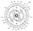
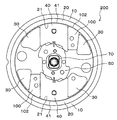
図1乃至図4は、実施例1に係るリクライニング装置200を示すものである。本実施例に係るリクライニング装置200は、「ベースプレート10」と「ギアプレート20」と「固定ガイド30」と「ロックギア40」と「カム50」と「スプリング60」と「センターシャフト70」と「可動ガイド100」と「スプリング」と「リンクプレート120」とを有するものである。以下、各構成要素毎に説明する。
Example 1
1 to 4 show a reclining device 200 according to the first embodiment. The reclining device 200 according to this embodiment includes a “base plate 10”, “gear plate 20”, “fixed guide 30”, “lock gear 40”, “cam 50”, “spring 60”, “center shaft 70”, and “ The movable guide 100 includes a “spring” and a “link plate 120”. Hereinafter, each component will be described.

まず「ベースプレート10」は、リクライニング装置200の基台を構成するものであって、車両用シートにおけるシートクッション又はシートバックの何れか一方に固定されるものである。このベースプレート10は、シートバックの荷重及び乗員の体重を支持可能な強度とする必要がある。従って、鋼鈑をプレス加工或いは切削加工することによって構成することが考えられる。なお、本実施例において当該ベースプレート10は、鋼鈑にプレス加工を施すことによって外形を円形に構成すると共に後述する固定ガイド30を構成し、これをシートクッション側に固定されるものとしている。   First, the “base plate 10” constitutes the base of the reclining device 200, and is fixed to either the seat cushion or the seat back in the vehicle seat. The base plate 10 needs to be strong enough to support the load on the seat back and the weight of the occupant. Therefore, it is conceivable to configure the steel sheet by pressing or cutting. In this embodiment, the base plate 10 has a circular outer shape by pressing a steel plate and a fixing guide 30 described later, and is fixed to the seat cushion side.

次に「ギアプレート20」は、上記ベースプレート10に対して回転可能に組み付けられると共に、車両用シートにおけるシートクッション又はシートバックの(ベースプレート10が固定されていない)何れか他方に固定されるものである。このギアプレート20は、シートバック(又はシートクッション)が固定される面とは反対側の内周に「内歯21」を形成している。この内歯21は後述するロックギア40の外歯41と噛合可能なものであり、当該ロックギア40との噛合により、シートバックの前後方向への傾動をロックするものである。このギアプレート20は、シートバックの荷重及び乗員の体重を支持可能な強度とする必要がある。従って、鋼鈑をプレス加工或いは切削加工することによって構成することが考えられる。なお、本実施例において当該ギアプレート20は、鋼鈑にプレス加工を施すことによって外形を円形に構成すると共に内歯21を構成し、これをシートバック側に固定されるものとしている。   Next, the “gear plate 20” is assembled to the base plate 10 so as to be rotatable, and is fixed to either the seat cushion or the seat back of the vehicle seat (the base plate 10 is not fixed). is there. This gear plate 20 forms “inner teeth 21” on the inner periphery opposite to the surface to which the seat back (or seat cushion) is fixed. The internal teeth 21 can mesh with external teeth 41 of a lock gear 40 described later, and lock the tilt of the seat back in the front-rear direction by meshing with the lock gear 40. The gear plate 20 needs to be strong enough to support the load on the seat back and the weight of the occupant. Therefore, it can be considered that the steel sheet is constituted by pressing or cutting. In the present embodiment, the gear plate 20 is formed by pressing a steel plate to form a circular outer shape and to form an inner tooth 21 that is fixed to the seat back side.

また「固定ガイド30」は、上記ベースプレート10における偏心の2箇所に1対ずつ一体的に設けられると共に、後述するロックギア40及び可動ガイド100をそれぞれ挟持するものである。この固定ガイド30には、シートバックの荷重及び乗員の体重が集中するため、これらの荷重を支持可能な強度とする必要がある。従って、鋼鈑をプレス加工或いは切削加工することによって構成することが考えられる。なお、本実施例において当該固定ガイド30は、鋼鈑をプレス加工してベースプレート10を構成する際に、裏側から金型で押し出すことにより突出させて構成するものとしている。   In addition, the “fixed guides 30” are integrally provided in pairs at two eccentric positions in the base plate 10 and sandwich a lock gear 40 and a movable guide 100 described later, respectively. Since the seat back load and the weight of the occupant are concentrated on the fixed guide 30, it is necessary to have such strength that the load can be supported. Therefore, it can be considered that the steel sheet is constituted by pressing or cutting. In the present embodiment, when the base plate 10 is formed by pressing a steel plate, the fixed guide 30 is configured to protrude by being pushed out from the back side with a mold.

さらに「ロックギア40」は、その両側面を平行に形成して上記固定ガイド30の間を摺動可能とすると共に、当該両側面どうしを結ぶ一辺に「外歯41」を形成して上記ギアプレート20の内歯21との噛合を可能とするものである。このロックギア40は、その外歯41がギアプレート20の内歯21に噛合した際には、ギアプレート20からの荷重を第一次的に負担するため、このような荷重にも耐えられる強度にて構成する必要がある。従って当該ロックギア40は、鋼鈑をプレス加工或いは切削加工することによって母材を形成した後に焼入れを行うか、或いは、鍛造するなどして構成することが考えられる。なお、本実施例において当該ロックギア40は、鋼鈑をプレス加工した後に焼入れをして構成するものとし、更には、後述するリンクプレート120との接合を可能とすべく、突起部42が設けられている。また、図面上明確に表れてはいないが、当該ロックギア40は、その両側摺動面の中央付近を窪ませて形成されている。即ち、両側の中央付近がくびれた状態となっているのである(図4参照)。そのため、当該ロックギア40は、(ベースプレートを基準として)外側端部付近と内側端部付近の2箇所で、固定ガイド30又は可動ガイド100と当接することとなる。つまり、斯様に構成することにより、各部材を完全な平面に形成して相互に密着させた場合に比して、当該ロックギア40の摺動をより容易なものとすることができるのである。   Further, the “lock gear 40” is formed so that both side surfaces thereof are parallel to be slidable between the fixed guides 30 and “external teeth 41” are formed on one side connecting the both side surfaces. Engagement with the internal teeth 21 of the plate 20 is enabled. Since the lock gear 40 primarily bears the load from the gear plate 20 when the outer teeth 41 mesh with the inner teeth 21 of the gear plate 20, the lock gear 40 is strong enough to withstand such loads. It is necessary to configure with. Therefore, the lock gear 40 can be configured by quenching or forging after forming the base material by pressing or cutting the steel sheet. In this embodiment, the lock gear 40 is formed by quenching after pressing a steel plate, and further, a protrusion 42 is provided so as to be able to be joined to a link plate 120 described later. It has been. Further, although not clearly shown in the drawing, the lock gear 40 is formed by recessing the vicinity of the center of the sliding surfaces on both sides. That is, the center of both sides is constricted (see FIG. 4). Therefore, the lock gear 40 comes into contact with the fixed guide 30 or the movable guide 100 at two locations near the outer end and the inner end (based on the base plate). That is, by configuring in this way, it is possible to make the sliding of the lock gear 40 easier than in the case where the respective members are formed on a complete plane and brought into close contact with each other. .

「カム50」は、上記ベースプレート10の略中心位置に配置され後述のシャフト70を挿通されて、当該シャフト70と同時回転することにより上記ロックギア40の移動(摺動)を制御するものである。即ち、当該カム50の回転によって、当該ロックギア40のギアプレート20に対する噛合及びその解除が行われ、ひいては、本リクライニング装置200が装着されたシートバックの前後方向における傾動のロック及びその解除が行われるのである。なお、本実施例において当該カム50には、後述するセンターシャフト70の角柱部71を挿通可能な角穴52を穿設すると共に、後述するリンクプレート120との接合を可能とすべく2つの突起部51が設けられている。   The “cam 50” is disposed substantially at the center of the base plate 10 and is inserted through a shaft 70 described later, and controls the movement (sliding) of the lock gear 40 by rotating simultaneously with the shaft 70. . That is, the rotation of the cam 50 causes the lock gear 40 to engage with the gear plate 20 and release it, and consequently locks and releases the tilt in the front-rear direction of the seat back on which the reclining device 200 is mounted. It is. In this embodiment, the cam 50 is provided with a square hole 52 through which a prismatic portion 71 of a center shaft 70 described later can be inserted, and two protrusions so as to be able to be joined to a link plate 120 described later. A part 51 is provided.

「スプリング60」は、上記カム50を回転付勢して、上記ロックギア40がギアプレート20の内歯21に噛合した状態を維持するものである。本実施例において当該スプリング60には渦巻きバネを採用し、その一端は上記カム50に係合させ、他端はベースプレート10に突設した係合突起に係合させるものとしている。なお、本発明は斯様な構成に限るものではなく、次述するセンターシャフト70をスプリング(図示しない)を装着することによって回転付勢するものとしてもよい。   The “spring 60” is configured to urge the cam 50 to maintain a state where the lock gear 40 is engaged with the internal teeth 21 of the gear plate 20. In the present embodiment, a spiral spring is employed for the spring 60, one end of which is engaged with the cam 50, and the other end is engaged with an engaging protrusion protruding from the base plate 10. The present invention is not limited to such a configuration, and the center shaft 70 described below may be rotationally biased by attaching a spring (not shown).

「センターシャフト70」は、ベースプレート10及びギアプレート20の中心部にそれぞれ穿設された貫通穴に挿通して、これらベースプレート10及びギアプレート20を同軸枢支するものである。更に当該センターシャフト70は、別部材に係る「操作レバー72」が装着されるものであり、乗員が当該操作レバー72を手動操作した場合には、上記ベースプレート10とギアプレート20との間において挿通されたカム50及びリンクプレート120が同時回転して、上記ロックギア40のギアプレート20に対する噛合及びその解除が行われることとなる。なお、本実施例において当該センターシャフト70は、鋼材を切削加工することによって構成している。より具体的には、当該センターシャフト70の略中間部付近には、上記カム50及びリンクプレート120に形成した角穴121に挿通可能な角柱部71が設けられている。そして、該センターシャフト70における一方の端部には操作レバー72を装着可能に構成すると共に、他方の端部には(図示しない)連結シャフトとの連結が可能なセレーション73を形成している。何故なら、リクライニング装置200は車両用シートの左右両側の連結部に装着されるものであるところ、シート左側のリクライニング装置200におけるカム50の回転と、シート右側のリクライニング装置200におけるカム50の回転とを、連結シャフトを介して同期させる必要があるからである。   The “center shaft 70” is inserted through through holes formed in the center portions of the base plate 10 and the gear plate 20, and coaxially supports the base plate 10 and the gear plate 20. Further, the center shaft 70 is provided with an “operation lever 72” according to another member. When the occupant manually operates the operation lever 72, the center shaft 70 is inserted between the base plate 10 and the gear plate 20. The cam 50 and the link plate 120 thus rotated simultaneously rotate so that the locking gear 40 is engaged with and released from the gear plate 20. In this embodiment, the center shaft 70 is formed by cutting a steel material. More specifically, a prism portion 71 that can be inserted into a square hole 121 formed in the cam 50 and the link plate 120 is provided in the vicinity of a substantially middle portion of the center shaft 70. An operation lever 72 can be attached to one end of the center shaft 70, and a serration 73 that can be connected to a connection shaft (not shown) is formed at the other end. This is because the reclining device 200 is attached to the left and right connecting portions of the vehicle seat. The rotation of the cam 50 in the reclining device 200 on the left side of the seat and the rotation of the cam 50 in the reclining device 200 on the right side of the seat This is because it is necessary to synchronize them via the connecting shaft.

「可動ガイド100」は、一方端から他方端に向かって漸次幅が狭くなるよう「楔形」に形成して、上記ロックギア40と固定ガイド30との間に摺動可能に介在させるものである。当該可動ガイド100には後述のスプリングが係合されており、当該スプリングによってベースプレート10の内方向へと付勢される。斯様に構成することにより、当該可動ガイド100は上記ロックギア40と固定ガイド30との間に常に食い込んだ状態となり、これら固定ガイド30とロックギア40と可動ガイド100とが相互に緊合して(堅く合わさって)、各部材間における隙間が消滅する。そのため、シートバックの前後方向におけるガタが解消されることとなる。また、当該可動ガイド100は、ロックギア40側の摺動面がロックギア40の移動方向に対して平行に設けられるため、該可動ガイド100がロックギア40に食い込むことによる該ロックギア40の固着という事態は起こらない。なお、本実施例において当該可動ガイド100は、鋼鈑を楔形にプレス加工した後に焼入れをして構成するものとし、更には、後述するリンクプレート120との接合を可能とすべく、突起部101が設けられている。また、図面上明確に表れてはいないが、当該可動ガイド100は、その両側摺動面の中央付近を窪ませて形成されている。即ち、両側の中央付近がくびれた状態となっているのである(図4参照)。そのため、当該可動ガイド100は、(ベースプレートを基準として)外側端部付近と内側端部付近の2箇所で、固定ガイド30又はロックギア40と当接することとなる。つまり、斯様に構成することにより、各部材を完全な平面に形成して相互に密着させた場合に比して、当該可動ガイド100の摺動をより容易なものとすることができるのである。   The “movable guide 100” is formed in a “wedge shape” so that the width gradually decreases from one end toward the other end, and is slidably interposed between the lock gear 40 and the fixed guide 30. . A spring described later is engaged with the movable guide 100 and is urged inward of the base plate 10 by the spring. With such a configuration, the movable guide 100 is always in a state of being bitten between the lock gear 40 and the fixed guide 30, and the fixed guide 30, the lock gear 40, and the movable guide 100 are tightly coupled to each other. The gaps between the members disappear. Therefore, the backlash in the front-rear direction of the seat back is eliminated. Further, since the movable guide 100 has a sliding surface on the lock gear 40 side parallel to the moving direction of the lock gear 40, the lock guide 40 is fixed when the movable guide 100 bites into the lock gear 40. This does not happen. In this embodiment, the movable guide 100 is configured by quenching after pressing a steel plate into a wedge shape, and further, the protrusion 101 to enable joining with a link plate 120 described later. Is provided. Although not clearly shown in the drawing, the movable guide 100 is formed by recessing the vicinity of the center of the sliding surfaces on both sides. That is, the center of both sides is constricted (see FIG. 4). Therefore, the movable guide 100 comes into contact with the fixed guide 30 or the lock gear 40 at two locations near the outer end and the inner end (based on the base plate). That is, by configuring in this way, sliding of the movable guide 100 can be made easier as compared with the case where the respective members are formed in a complete plane and brought into close contact with each other. .

「スプリング」は、固定ガイド30とロックギア40との間に介在させた可動ガイド100に係合されて、該可動ガイド100をベースプレート10の内方向へと付勢するものである。なお、本実施例において当該スプリングは、円弧状の棒状部材からなるトーションスプリング110にて構成し、その両端を屈曲させてなる係合部をそれぞれ可動ガイド100に係合させて、各可動ガイド100を引き寄せるように付勢している。但し、本発明は上記構成に限定されるものではなく、ベースプレート10側に(図示しない)被係合部を設けるなどして、各々の可動ガイド100を別個のスプリングで付勢することも考えられる。   The “spring” is engaged with the movable guide 100 interposed between the fixed guide 30 and the lock gear 40 and biases the movable guide 100 inward of the base plate 10. In this embodiment, the spring is constituted by a torsion spring 110 made of an arc-shaped bar-like member, and engaging portions formed by bending both ends thereof are engaged with the movable guides 100, respectively. It is energized to attract. However, the present invention is not limited to the above-described configuration, and it is conceivable that each movable guide 100 is biased by a separate spring by providing an engaged portion (not shown) on the base plate 10 side. .

そして「リンクプレート120」は、上記カム50が回転することによりギアプレート20の内歯21に対するロックギア40の噛合を解除するときに(より好適には、ギアプレート20の内歯21に対するロックギア40の噛合の解除に先だって)、前記カム50と同時回転して可動ガイド100を外方向に押し出すものである。本発明においては、「ガタ」の原因となる固定ガイド30とロックギア40との間の「隙間」を解消するべく、固定ガイド30とロックギア40との間に可動ガイド100を介在させると共に、これらは強固に緊合した状態となっている。かかる状態においてシートバックの傾動のロックを解除すべくカム50を回転させただけでは、当該ロックギア40は固定ガイド30と可動ガイド100との間で固着して、該ロックギア40のギアプレート20に対する噛合が解除されない場合も生じうる。従って、ロックギア40をベースプレート10内方向への引き込むのに際して(先立って)、可動ガイド100を外方向に押し出すことによって当該可動ガイド100とロックギア40との緊合を解除して、当該ロックギア40が自由に摺動できるようにしたのである。なお、本実施例において当該リンクプレート120は、薄鈑にて構成した円形の中心位置に前記シャフト角柱部71を挿通可能な角穴121を穿設し、前記カム50の突起部51を挿通可能な丸穴122を穿設して、前記ロックギア40の突起部42を挿通可能な略扇状の穴123を穿設すると共に、当該円形の外周2箇所に前記可動ガイド100の突起部101を当接可能な凹部124を設けてなるものである。ここで、当該リンクプレート120は、該リンクプレート120を回転させた際、前記「略扇状の穴123」の外側縁がロックギア40の突起部42に当接するよりも早いタイミングで、前記「凹部124」の外側縁が可動ガイド100の突起部101に当接するように設定している。そのため、本リクライニング装置200のロック解除を行うべくセンターシャフト70を回転させた際には、先ずリンクプレート120の凹部124が可動ガイド100の突起部101を外方向に押し出し、しかる後、当該リンクプレート120略扇状の穴123によってロックギア40を内方向に向けてスムースに引き込むこととなるため、各部材間における負荷を軽減することが可能となるのである。   The “link plate 120” is used when the locking of the lock gear 40 with the internal teeth 21 of the gear plate 20 is released by the rotation of the cam 50 (more preferably, the lock gear with respect to the internal teeth 21 of the gear plate 20). 40), the movable guide 100 is pushed outward by rotating simultaneously with the cam 50. In the present invention, the movable guide 100 is interposed between the fixed guide 30 and the lock gear 40 in order to eliminate the “gap” between the fixed guide 30 and the lock gear 40 that causes “backlash”. These are in a tightly coupled state. In this state, the lock gear 40 is fixed between the fixed guide 30 and the movable guide 100 only by rotating the cam 50 so as to release the tilting lock of the seat back, and the gear plate 20 of the lock gear 40 is fixed. There is also a case where the meshing with respect to is not released. Accordingly, when the lock gear 40 is pulled inwardly (in advance), the movable guide 100 is pushed outward to release the engagement between the movable guide 100 and the lock gear 40, so that the lock gear 40 is released. 40 was allowed to slide freely. In this embodiment, the link plate 120 is formed with a square hole 121 through which the shaft prismatic portion 71 can be inserted at a circular center position formed by a thin wall, and the projection 51 of the cam 50 can be inserted. A circular hole 122 is drilled to form a substantially fan-shaped hole 123 into which the protrusion 42 of the lock gear 40 can be inserted, and the protrusion 101 of the movable guide 100 is abutted at two locations on the outer periphery of the circle. A contactable recess 124 is provided. Here, when the link plate 120 is rotated, the “recessed portion” is formed at a timing earlier than the outer edge of the “substantially fan-shaped hole 123” abuts the protrusion 42 of the lock gear 40. The outer edge of 124 ”is set so as to contact the protrusion 101 of the movable guide 100. Therefore, when the center shaft 70 is rotated to unlock the reclining device 200, the concave portion 124 of the link plate 120 first pushes the protrusion 101 of the movable guide 100 outward, and then the link plate Since the lock gear 40 is smoothly pulled inward by the substantially fan-shaped hole 123, the load between the members can be reduced.

続いて、上記構成からなる本実施例に係るリクライニング装置200の動作について 図1乃至図4を用いて説明する。   Next, the operation of the reclining device 200 according to this embodiment having the above-described configuration will be described with reference to FIGS.

まず、本実施例に係るリクライニング装置200においてシートバックの前後方向における傾動をロックする場合、乗員は操作レバー72を開放することとなる。操作レバー72の開放時には、図1及び図3に示すように、スプリング60によって図面上反時計回り方向に付勢されたカム50が回転し、ロックギア40が固定ガイド30に沿ってベースプレート10における外方向へと押し出されるように摺動し、当該ロックギア40の外歯41がギアプレート20内周の内歯21へと噛合して、シートバックの前後方向における傾動がロックされることとなる。このとき、当該ロックギア40と固定ガイド30との間にはスプリングによって付勢された可動ガイド100が強固に食い込むこととなり、これら固定ガイド30とロックギア40と可動ガイド100とは相互に緊合して、各部材間における隙間が消滅することとなる。そのため当該シートバックは、傾動がロックされた状態においても前後方向へのガタが発生しないのである。   First, when locking the tilting of the seat back in the front-rear direction in the reclining device 200 according to this embodiment, the occupant opens the operation lever 72. When the operation lever 72 is opened, as shown in FIGS. 1 and 3, the cam 50 urged counterclockwise by the spring 60 rotates, and the lock gear 40 moves along the fixed guide 30 in the base plate 10. The outer teeth 41 of the lock gear 40 are slid so as to be pushed outward, and the outer teeth 41 of the lock gear 40 are engaged with the inner teeth 21 of the inner periphery of the gear plate 20 to lock the tilting of the seat back in the front-rear direction. . At this time, the movable guide 100 urged by the spring firmly bites between the lock gear 40 and the fixed guide 30, and the fixed guide 30, the lock gear 40, and the movable guide 100 are in close contact with each other. As a result, the gap between the members disappears. Therefore, the back of the seatback does not occur in the front-rear direction even when the tilt is locked.

一方、本実施例に係るリクライニング装置200においてシートバックの前後方向における傾動のロックを解除する場合、乗員は操作レバー72を引き上げる(又は、押し下げる)こととなる。操作レバー72の回動によって当該操作レバー72が装着されたセンターシャフト70が回転するのに伴い、図2及び図4に示すように、センターシャフト70が挿通されたカム50及びリンクプレート120も同時に回転することとなる。カム50の回転によって当該カム50とロックギア40との間に隙間が生じる。また、リンクプレート120の回転によって該リンクプレート120に係る凹部124の外側縁が可動ガイド100の突起部101に当接して、該可動ガイド100をベースプレート10における外方向へと押し出して、該可動ガイド100と固定ガイド30とロックギア40との強固な緊合を解除する。その後、当該リンクプレート120に係る略扇状の穴123の外側縁がロックギア40の突起部42に当接して当該ロックギア40が内方向に向けてスムースに引き込まれて、シートバックの前後方向における傾動が可能な状態となる。これら一連の動作を、若干タイミングをずらしながらほぼ同時に行われることとなる。   On the other hand, in the reclining device 200 according to the present embodiment, when unlocking the tilting of the seat back in the front-rear direction, the occupant pulls up (or pushes down) the operation lever 72. As the center shaft 70 to which the operation lever 72 is attached is rotated by the rotation of the operation lever 72, the cam 50 and the link plate 120 through which the center shaft 70 is inserted are simultaneously shown in FIGS. It will rotate. A gap is generated between the cam 50 and the lock gear 40 by the rotation of the cam 50. Further, the outer edge of the concave portion 124 of the link plate 120 abuts against the protrusion 101 of the movable guide 100 by the rotation of the link plate 120, and the movable guide 100 is pushed outward in the base plate 10, thereby moving the movable guide 100. 100, the fixed guide 30, and the lock gear 40 are released. Thereafter, the outer edge of the substantially fan-shaped hole 123 related to the link plate 120 abuts on the protrusion 42 of the lock gear 40, and the lock gear 40 is smoothly pulled inward, so that the seat back in the front-rear direction Tilt is possible. These series of operations are performed almost at the same time with a slight shift in timing.

(実施例2)
図5は、実施例2に係るリクライニング装置200を示すものである。本実施例に係るリクライニング装置200は、上記実施例1と多くの部分で共通するため、特に上記実施例1と異なる構成につき詳説し、共通する構成についてはその説明を省略する。本実施例においては、図5に示すように、カム50が渦巻き状のトーションスプリング60によって回転付勢されている。尚、本実施例においては、説明の便宜上リンクプレート120は特段図示していないが、勿論、此を備える構成としてもよい。本実施例によれば、カム50への回転付勢が1本のトーションスプリング60によってなされていることから、実施例1に比して少ない部品点数でリクライニング装置200を提供することが可能となるのである。
(Example 2)
FIG. 5 shows a reclining device 200 according to the second embodiment. Since the reclining device 200 according to the present embodiment is common to the first embodiment in many parts, the configuration different from the first embodiment will be described in detail, and the description of the common configuration will be omitted. In the present embodiment, as shown in FIG. 5, the cam 50 is urged to rotate by a spiral torsion spring 60. In the present embodiment, the link plate 120 is not particularly shown for convenience of explanation, but of course, it may be configured to include this. According to the present embodiment, since the rotation urging force to the cam 50 is made by one torsion spring 60, the reclining device 200 can be provided with a smaller number of parts than the first embodiment. It is.

(実施例3)
図6は、実施例3に係るリクライニング装置200を示すものである。本実施例に係るリクライニング装置200は、上記実施例1と多くの部分で共通するため、特に上記実施例1と異なる構成につき詳説し、共通する構成についてはその説明を省略する。図6に示すように、本実施例においてカム50は、他方端を可動ガイド100に係合させた2本のトーションスプリング110によって回転付勢されている。そのためこれら2本のトーションスプリング110が、カム50と可動ガイド100とに係合され、これらをセンターシャフト70を跨いで対角線上に引き込むため、当該カム50を2方向から均等に回転付勢することとなる。そのため本実施例によれば、前記カム50に対し偏心方向への付勢力が及ばないことから、該カム50をベースプレート10の中心で回転させることができる。即ち、該カム50の押圧力が、2つのロックギア40のうち何れか一方に偏ることなく両方へと均等に及ぶため、これら両方のロックギア40の外歯41がギアプレート20の内歯21にそれぞれ噛合して、確実なロックが実現するのである。尚、本実施例では、2本のトーションスプリング110が、カム50と可動ガイド100とに係合され、これらをセンターシャフト70を跨いで対角線上に引き込む構成としているが、本発明は特段この構成に限定されるものではない。即ち、前記カム50を対角線上に引き込んで回転付勢できるのであれば、当該カム50と該カム50における被係合部の直近に配置した可動ガイド100とを連結する構成を採用してもよい。また、上記「2本のトーションスプリング110」は、図6に示す形態に限定されるものでなく、図7或いは図8に示す形態を採用してもよい。更に本実施例においては、説明の便宜上リンクプレート120は特段図示していないが、勿論、此を備える構成としてもよい。
(Example 3)
FIG. 6 shows a reclining device 200 according to the third embodiment. Since the reclining device 200 according to the present embodiment is common to the first embodiment in many parts, the configuration different from the first embodiment will be described in detail, and the description of the common configuration will be omitted. As shown in FIG. 6, in this embodiment, the cam 50 is rotationally biased by two torsion springs 110 having the other end engaged with the movable guide 100. For this reason, these two torsion springs 110 are engaged with the cam 50 and the movable guide 100, and in order to draw them diagonally across the center shaft 70, the cam 50 is equally rotationally biased from two directions. It becomes. Therefore, according to this embodiment, since the biasing force in the eccentric direction is not exerted on the cam 50, the cam 50 can be rotated at the center of the base plate 10. That is, since the pressing force of the cam 50 is evenly distributed to both of the two lock gears 40 without being biased to one of the two lock gears 40, the external teeth 41 of both the lock gears 40 are connected to the internal teeth 21 of the gear plate 20. Thus, a reliable lock is achieved. In the present embodiment, the two torsion springs 110 are engaged with the cam 50 and the movable guide 100, and are drawn in a diagonal line across the center shaft 70. It is not limited to. That is, as long as the cam 50 can be pulled in a diagonal line to be urged to rotate, a configuration in which the cam 50 and the movable guide 100 disposed in the immediate vicinity of the engaged portion of the cam 50 may be employed. . Further, the “two torsion springs 110” are not limited to the form shown in FIG. 6, and the form shown in FIG. 7 or 8 may be adopted. Further, in the present embodiment, the link plate 120 is not particularly shown for convenience of explanation, but of course, it may be configured to include this.

(実施例4)
図9は、実施例4に係るリクライニング装置200を示すものである。本実施例に係るリクライニング装置200は、上記実施例1と多くの部分で共通するため、特に上記実施例1と異なる構成につき詳説し、共通する構成についてはその説明を省略する。図9に示すように、本実施例においてロックギア40は、内方端から外方端に向かって漸次幅が狭く形成されると共に、当該ロックギア40における固定ガイド30側の摺動面は、該ロックギア40の移動方向と平行に設けられている。そのため、当該ロックギア40における可動ガイド100側には傾斜面が構成される。そして、この傾斜面と固定ガイド30との間に「楔形」の可動ガイド100が介入し、その摺動面どうしを密着させ、当該ロックギア40における外歯41がギアプレート20の内歯21に係合することにより、該ギアプレート20の回転(即ち、リクライニング)をロックすることとなる。一方、リクライニングのロックを解除する際には、センターシャフト70を回転させてロックギア40における外歯41とギアプレート20における内歯21との噛合を解除することとなる。この点、本実施例においては、ロックギア40と可動ガイド100との当接面が該ロックギア40の移動方向に対して傾斜しているため、ロックギア40が内方向に引き込まれた際にも、これらロックギア40と可動ガイド100との間で殆ど摩擦が生じることなく相互に離間させることができる。従って、本実施例によれば、ロックの解除に際し、敢えてリンクプレート120によって可動ガイド100を外方へ押し出さなくとも、ロックギア40を内方向へとスムースに引き込むことができるため、少ない部品点数でリクライニング装置200を構成することができるのである。勿論、リンクプレート120を備える構成としてもよい。
(Example 4)
FIG. 9 shows a reclining device 200 according to the fourth embodiment. Since the reclining device 200 according to the present embodiment is common to the first embodiment in many parts, the configuration different from the first embodiment will be described in detail, and the description of the common configuration will be omitted. As shown in FIG. 9, in this embodiment, the lock gear 40 is formed so that the width gradually decreases from the inner end toward the outer end, and the sliding surface of the lock gear 40 on the fixed guide 30 side is The lock gear 40 is provided in parallel with the moving direction. Therefore, an inclined surface is formed on the movable guide 100 side of the lock gear 40. Then, a “wedge-shaped” movable guide 100 intervenes between the inclined surface and the fixed guide 30, the sliding surfaces are brought into close contact with each other, and the external teeth 41 in the lock gear 40 contact the internal teeth 21 of the gear plate 20. By engaging, the rotation (that is, reclining) of the gear plate 20 is locked. On the other hand, when the reclining lock is released, the center shaft 70 is rotated to release the engagement between the external teeth 41 in the lock gear 40 and the internal teeth 21 in the gear plate 20. In this respect, in the present embodiment, the contact surface between the lock gear 40 and the movable guide 100 is inclined with respect to the movement direction of the lock gear 40, and therefore when the lock gear 40 is pulled inward. However, the lock gear 40 and the movable guide 100 can be separated from each other with almost no friction. Therefore, according to the present embodiment, when releasing the lock, the lock gear 40 can be smoothly pulled inward without pushing the movable guide 100 outward by the link plate 120, so the number of parts can be reduced. The reclining device 200 can be configured. Of course, it is good also as a structure provided with the link plate 120. FIG.

(実施例5)
図10及び図11は、実施例5に係るリクライニング装置200を示すものである。本実施例に係るリクライニング装置200は、上記実施例1と多くの部分で共通するため、特に上記実施例1と異なる構成につき詳説し、共通する構成についてはその説明を省略する。図10に示すように、本実施例において可動ガイド100は、その外方端にギアプレート20における内歯21と係合可能な外歯102を有している。そのため本実施例によれば、車両衝突時など、当該リクライニング装置200に過大な荷重が入力されたときには、ギアプレート20からロックギア40へと回転荷重が及び、該ロックギア40が固定ガイド30との間で可動ガイド100を押圧するように作用することとなる。ここで当該可動ガイド100は、外方端から内方端に向かって漸次幅が狭く形成されていることから、図11に示すように、ベースプレート10の外方向に押し出される。そのため、該可動ガイド100の外方端に形成した外歯102がギアプレート20の内歯21へと近接すると共に噛合して、ギアプレート20の回転を前記ロックギア40と共に規制することとなる。即ち、本実施例によれば、車両衝突事故発生時等、過大な荷重が本リクライニング装置200に及んだ際は、ロックギア40と共に可動ガイド100がギアプレート20の回転を規制するため、車両衝突時に伴う乗員の意図しないシートバックの傾動を防止することができるのである。尚、本実施例においては、説明の便宜上リンクプレート120は特段図示していないが、勿論、此を備える構成としてもよい。
(Example 5)
10 and 11 show a reclining device 200 according to the fifth embodiment. Since the reclining device 200 according to the present embodiment is common to the first embodiment in many parts, the configuration different from the first embodiment will be described in detail, and the description of the common configuration will be omitted. As shown in FIG. 10, in this embodiment, the movable guide 100 has external teeth 102 that can be engaged with the internal teeth 21 of the gear plate 20 at the outer end thereof. Therefore, according to the present embodiment, when an excessive load is input to the reclining device 200 such as at the time of a vehicle collision, a rotational load is applied from the gear plate 20 to the lock gear 40, and the lock gear 40 is connected to the fixed guide 30. It acts to press the movable guide 100 between. Here, since the movable guide 100 is formed so that the width gradually decreases from the outer end toward the inner end, the movable guide 100 is pushed outward of the base plate 10 as shown in FIG. For this reason, the external teeth 102 formed at the outer end of the movable guide 100 approach and mesh with the internal teeth 21 of the gear plate 20 to restrict the rotation of the gear plate 20 together with the lock gear 40. That is, according to the present embodiment, when an excessive load is applied to the reclining device 200 such as when a vehicle collision accident occurs, the movable guide 100 together with the lock gear 40 regulates the rotation of the gear plate 20. It is possible to prevent an unintended tilting of the seat back caused by a collision. In the present embodiment, the link plate 120 is not particularly shown for convenience of explanation, but of course, it may be configured to include this.

(実施例6)
図12は、実施例6に係るリクライニング装置200における可動ガイド100付近を拡大して示す図である。本実施例に係るリクライニング装置200は、上記実施例1と多くの部分で共通するため、特に上記実施例1と異なる構成につき詳説し、共通する構成についてはその説明を省略する。図12に示すように、本実施例において可動ガイド100は、該可動ガイド100における固定ガイド30側の摺動面の外方端側に、固定ガイド30と緊密に当接する当接部103を形成し、当該固定ガイドとの間に隙間を発生させるための段部104を、前記当接部103に連続して形成してなるものである。かかる構成を採ることにより、当該可動ガイド100は、前記固定ガイド30に対して専ら当接部103で密着することとなる。従って、本実施例によれば、固定ガイド30の形成寸法に若干の誤差が生じたとしても、可動ガイド100は必然的に外方端側にて前記固定ガイド30と緊密に密接するため、シートバックの前後方向に対するガタの発生を確実に防止することが可能となる。尚、本実施例においては、説明の便宜上リンクプレート120は特段図示していないが、勿論、此を備える構成としてもよい。
(Example 6)
FIG. 12 is an enlarged view of the vicinity of the movable guide 100 in the reclining device 200 according to the sixth embodiment. Since the reclining device 200 according to the present embodiment is common to the first embodiment in many parts, the configuration different from the first embodiment will be described in detail, and the description of the common configuration will be omitted. As shown in FIG. 12, in this embodiment, the movable guide 100 is formed with an abutting portion 103 that abuts the fixed guide 30 tightly on the outer end side of the sliding surface of the movable guide 100 on the fixed guide 30 side. A stepped portion 104 for generating a gap between the fixed guide and the contact portion 103 is formed continuously. By adopting such a configuration, the movable guide 100 comes into close contact with the fixed guide 30 exclusively at the contact portion 103. Therefore, according to the present embodiment, even if a slight error occurs in the formation dimension of the fixed guide 30, the movable guide 100 is necessarily in close contact with the fixed guide 30 on the outer end side. It is possible to reliably prevent backlash in the back-and-forth direction. In the present embodiment, the link plate 120 is not particularly shown for convenience of explanation, but of course, it may be configured to include this.

(実施例7)
図13及び図14は、実施例7に係るリクライニング装置200と、当該リクライニング装置200が装着される車両用シートのシートフレームを構成するブラケット300の一部を示すものである。まず図13に示す実施形態は、ベースプレート10裏面における上下左右のロックギア40どうしの間における4箇所に凸部11を突設させ、これら凸部11をブラケット300の4箇所に設けた穿孔部301内に進入させ、しかる後、当該箇所にアーク溶接を施して溶接部302を構成し、両部材を離間不可に一体化したものである。次に図14に示す実施形態は、ベースプレート10裏面におけるロックギア40及び可動ガイド100に相当する位置に平面部を形成すると共に、上下のロックギア40どうしの間における2箇所に凸部11を突設させ、これら凸部11をブラケット300の2箇所に設けた穿孔部301内に進入させる。しかる後、穿孔部301内に進入させた凸部11周縁及びブラケット300における平面部が当接する部分にレーザ溶接を施して溶接部302を構成し、両部材を離間不可に一体化したものである。特に、レーザ溶接を用いた場合には、接合に際し、ベースプレート10へのエンボス加工部を少なくすることができ、尚かつ、ブラケット300側に大きな開口部を設ける必要がない。即ち、各構成部材への塑性加工を最小限に抑えることができるので、高い強度を備えた車両用シートを提供することができるのである。
(Example 7)
FIGS. 13 and 14 show a part of a reclining device 200 according to the seventh embodiment and a bracket 300 constituting a seat frame of a vehicle seat to which the reclining device 200 is attached. First, in the embodiment shown in FIG. 13, projections 11 are provided at four locations between the upper, lower, left, and right lock gears 40 on the back surface of the base plate 10, and the projections 301 are provided at four locations on the bracket 300. Then, the welded portion 302 is formed by performing arc welding on the portion, and the two members are integrated so as not to be separated from each other. Next, in the embodiment shown in FIG. 14, a flat portion is formed at a position corresponding to the lock gear 40 and the movable guide 100 on the back surface of the base plate 10, and the protrusions 11 protrude at two places between the upper and lower lock gears 40. These protrusions 11 are inserted into the perforated portions 301 provided at two locations of the bracket 300. After that, laser welding is applied to the portion where the periphery of the convex portion 11 that has entered the perforated portion 301 and the flat portion of the bracket 300 abut to form a welded portion 302, and both members are integrated so as not to be separated. . In particular, when laser welding is used, it is possible to reduce the embossed portion of the base plate 10 when joining, and it is not necessary to provide a large opening on the bracket 300 side. That is, plastic working on each constituent member can be minimized, so that a vehicle seat having high strength can be provided.

(実施例8)
図15乃至図18は、実施例8に係るリクライニング装置200を示すものである。本実施例に係るリクライニング装置200は、「ベースプレート10」と「ギアプレート20」と「固定ガイド30」と「ロックギア40」と「カム50」と「バネ60」と「センターシャフト70」と「リンクプレート80」とを有するものである。以下、各構成要素毎に説明する。
(Example 8)
15 to 18 show a reclining device 200 according to the eighth embodiment. The reclining device 200 according to the present embodiment includes a “base plate 10”, “gear plate 20”, “fixed guide 30”, “lock gear 40”, “cam 50”, “spring 60”, “center shaft 70”, “ Link plate 80 ". Hereinafter, each component will be described.

まず「ベースプレート10」は、リクライニング装置200の基台を構成するものであって、車両用シートにおけるシートクッション又はシートバックの何れか一方に固定されるものである。このベースプレート10は、シートバックの荷重及び乗員の体重を支持可能な強度とする必要がある。従って、鋼鈑をプレス加工或いは切削加工することによって構成することが考えられる。なお、本実施例において当該ベースプレート10は、鋼鈑にプレス加工を施すことによって外形を円形に構成すると共に後述する固定ガイド30を構成し、これをシートクッション側に固定されるものとしている。   First, the “base plate 10” constitutes the base of the reclining device 200, and is fixed to either the seat cushion or the seat back in the vehicle seat. The base plate 10 needs to be strong enough to support the load of the seat back and the weight of the occupant. Therefore, it is conceivable to configure the steel sheet by pressing or cutting. In this embodiment, the base plate 10 has a circular outer shape by pressing a steel plate and a fixing guide 30 described later, and is fixed to the seat cushion side.

次に「ギアプレート20」は、上記ベースプレート10に対して回転可能に組み付けられると共に、車両用シートにおけるシートクッション又はシートバックの(ベースプレート10が固定されていない)何れか他方に固定されるものである。このギアプレート20は、シートバック(又はシートクッション)が固定される面とは反対側の内周に「内歯21」を形成している。この内歯21は後述するロックギア40の外歯41と噛合可能なものであり、当該ロックギア40との噛合により、シートバックの前後方向への傾動をロックするものである。このギアプレート20は、シートバックの荷重及び乗員の体重を支持可能な強度とする必要がある。従って、鋼鈑をプレス加工或いは切削加工することによって構成することが考えられる。なお、本実施例において当該ギアプレート20は、鋼鈑にプレス加工を施すことによって外形を円形に構成すると共に内歯21を構成し、これをシートバック側に固定されるものとしている。   Next, the “gear plate 20” is assembled to the base plate 10 so as to be rotatable, and is fixed to either the seat cushion or the seat back of the vehicle seat (the base plate 10 is not fixed). is there. This gear plate 20 forms “inner teeth 21” on the inner periphery opposite to the surface to which the seat back (or seat cushion) is fixed. The internal teeth 21 can mesh with external teeth 41 of a lock gear 40 described later, and lock the tilt of the seat back in the front-rear direction by meshing with the lock gear 40. The gear plate 20 needs to be strong enough to support the load on the seat back and the weight of the occupant. Therefore, it can be considered that the steel sheet is constituted by pressing or cutting. In the present embodiment, the gear plate 20 is formed by pressing a steel plate to form a circular outer shape and to form an inner tooth 21 that is fixed to the seat back side.

また「固定ガイド30」は、上記ベースプレート10における偏心の2箇所に1対ずつ一体的に設けられると共に、後述するロックギア40をそれぞれ挟持するものである。この固定ガイド30には、シートバックの荷重及び乗員の体重が集中するため、これらの荷重を支持可能な強度とする必要がある。従って、鋼鈑をプレス加工或いは切削加工することによって構成することが考えられる。なお、本実施例において当該固定ガイド30は、鋼鈑をプレス加工してベースプレート10を構成する際に、裏側から金型で押し出すことにより突出させて構成するものとしている。   Further, the “fixed guides 30” are integrally provided in pairs at two eccentric positions in the base plate 10 and each hold a lock gear 40 described later. Since the seat back load and the weight of the occupant are concentrated on the fixed guide 30, it is necessary to have such strength that the load can be supported. Therefore, it can be considered that the steel sheet is constituted by pressing or cutting. In the present embodiment, when the base plate 10 is formed by pressing a steel plate, the fixed guide 30 is configured to protrude by being pushed out from the back side with a mold.

但し、本発明において当該固定ガイド30は、その機械強度を前記ギアプレート20及び後述のロックギア40よりも低く設定する必要がある。当該リクライニング装置200に大きな荷重が入力されたとき(非常時)には、ロックギア40によって当該固定ガイド30が押圧されて変形し、その外端部31がギアプレート20の内歯21に対して当接可能とするためである。   However, in the present invention, the fixed guide 30 needs to have a mechanical strength lower than that of the gear plate 20 and a lock gear 40 described later. When a large load is input to the reclining device 200 (in an emergency), the fixed guide 30 is pressed and deformed by the lock gear 40, and the outer end 31 thereof is against the inner teeth 21 of the gear plate 20. This is for enabling contact.

また当該固定ガイド30は、その外端部31とギアプレート20の内歯21の先端とを可能な限り近接させて設けることも考えられる。斯様に構成することにより、当該固定ガイド30の変形時には、その外端部31によるギアプレート20の内歯21への食い込みが一層確実となる。   It is also conceivable that the fixed guide 30 is provided with its outer end 31 and the tip of the inner tooth 21 of the gear plate 20 as close as possible. By configuring in this way, when the fixed guide 30 is deformed, the outer end 31 bites the inner teeth 21 of the gear plate 20 more reliably.

更に当該固定ガイド30は、ベースプレート10とギアプレート20とを組み付けた際には、当該ギアプレート20と略密接状となる厚みにて形成することも考えられる。斯様に構成することにより、当該固定ガイド30の変形時には、その厚み方向への変形をギアプレート20で押さえ込むこととなり、該固定ガイド30の変形量の大半をギアプレート20の内歯21への食い込みに充てることができる。   Further, it is conceivable that the fixed guide 30 is formed with a thickness that is substantially in close contact with the gear plate 20 when the base plate 10 and the gear plate 20 are assembled. With such a configuration, when the fixed guide 30 is deformed, the deformation in the thickness direction is suppressed by the gear plate 20, and most of the deformation amount of the fixed guide 30 is applied to the inner teeth 21 of the gear plate 20. Can be used for biting.

「ロックギア40」は、その両側面を平行に形成して上記固定ガイド30の間を摺動可能とすると共に、当該両側面どうしを結ぶ一辺に「外歯41」を形成して上記ギアプレート20の内歯21との噛合を可能とするものである。このロックギア40は、その外歯41がギアプレート20の内歯21に噛合した際には、ギアプレート20からの荷重を第一次的に負担するため、このような荷重にも耐えられる強度にて構成する必要がある。従って当該ロックギア40は、鋼鈑をプレス加工或いは切削加工することによって母材を形成した後に焼入れを行うか、或いは、鍛造するなどして構成することが考えられる。なお、本実施例において当該ロックギア40は、鋼鈑をプレス加工した後に焼入れをして構成するものとし、更には、後述するリンクプレート80との接合を可能とすべく、突起部42が設けられている。   The “lock gear 40” is formed so that both side surfaces thereof are parallel to be slidable between the fixed guides 30 and “external teeth 41” are formed on one side connecting the both side surfaces to form the gear plate. It is possible to engage with the 20 internal teeth 21. Since the lock gear 40 primarily bears the load from the gear plate 20 when the outer teeth 41 mesh with the inner teeth 21 of the gear plate 20, the lock gear 40 is strong enough to withstand such loads. It is necessary to configure with. Therefore, the lock gear 40 can be configured by quenching or forging after forming the base material by pressing or cutting the steel sheet. In this embodiment, the lock gear 40 is configured by quenching after pressing a steel plate, and further, a protrusion 42 is provided to enable joining to a link plate 80 described later. It has been.

「カム50」は、上記ベースプレート10の略中心位置に配置され後述のシャフト70を挿通されて、当該シャフト70と同時回転することにより上記ロックギア40の移動(摺動)を制御するものである。即ち、当該カム50の回転によって、当該ロックギア40のギアプレート20に対する噛合及びその解除が行われ、ひいては、本リクライニング装置200が装着されたシートバックの前後方向における傾動のロック及びその解除が行われるのである。なお、本実施例において当該カム50には、後述するセンターシャフト70の角柱部71を挿通可能な角穴52を穿設すると共に、後述するリンクプレート80との接合を可能とすべく2つの突起部51が設けられている。   The “cam 50” is disposed substantially at the center of the base plate 10 and is inserted through a shaft 70 described later, and controls the movement (sliding) of the lock gear 40 by rotating simultaneously with the shaft 70. . That is, the rotation of the cam 50 causes the lock gear 40 to engage with the gear plate 20 and release it, and consequently locks and releases the tilt in the front-rear direction of the seat back on which the reclining device 200 is mounted. It is. In this embodiment, the cam 50 is provided with a square hole 52 through which a prism 71 of the center shaft 70 described later can be inserted, and two protrusions so as to be able to be joined to a link plate 80 described later. A part 51 is provided.

「バネ60」は、上記カム50を回転付勢して、上記ロックギア40がギアプレート20の内歯21に噛合した状態を維持するものである。本実施例において当該バネ60には渦巻きバネ60を採用し、その一端は上記カム50に係合させ、他端はベースプレート10に突設した係合突起に係合させるものとしている。なお、本発明は斯様な構成に限るものではなく、次述するセンターシャフト70にバネ60(図示しない)を装着することによって回転付勢するものとしてもよい。   The “spring 60” is configured to rotate and bias the cam 50 and maintain the lock gear 40 in mesh with the internal teeth 21 of the gear plate 20. In this embodiment, a spiral spring 60 is employed as the spring 60, one end of which is engaged with the cam 50, and the other end is engaged with an engaging protrusion protruding from the base plate 10. The present invention is not limited to such a configuration, and may be rotationally biased by attaching a spring 60 (not shown) to the center shaft 70 described below.

「センターシャフト70」は、ベースプレート10及びギアプレート20の中心部にそれぞれ穿設された貫通穴に挿通して、これらベースプレート10及びギアプレート20を同軸枢支するものである。更に当該センターシャフト70は、別部材に係る「操作レバー72」が装着されるものであり、乗員が当該操作レバー72を手動操作した場合には、上記ベースプレート10とギアプレート20との間において挿通されたカム50及びリンクプレート80が同時回転して、上記ロックギア40のギアプレート20に対する噛合及びその解除が行われることとなる。なお、本実施例において当該センターシャフト70は、鋼材を切削加工することによって構成している。より具体的には、当該センターシャフト70の略中間部付近には、上記カム50及びリンクプレート80に形成した角穴81に挿通可能な角柱部71が設けられている。そして、該センターシャフト70における一方の端部には操作レバー72を装着可能に構成すると共に、他方の端部には(図示しない)連結シャフトとの連結が可能なセレーション73を形成している。何故なら、リクライニング装置200は車両用シートの左右両側の連結部に装着されるものであるところ、シート左側のリクライニング装置200におけるカム50の回転と、シート右側のリクライニング装置200におけるカム50の回転とを、連結シャフトを介して同期させる必要があるからである。   The “center shaft 70” is inserted through through holes formed in the center portions of the base plate 10 and the gear plate 20, and coaxially supports the base plate 10 and the gear plate 20. Further, the center shaft 70 is provided with an “operation lever 72” according to another member. When the occupant manually operates the operation lever 72, the center shaft 70 is inserted between the base plate 10 and the gear plate 20. The cam 50 and the link plate 80 thus rotated simultaneously rotate so that the lock gear 40 is engaged with and released from the gear plate 20. In this embodiment, the center shaft 70 is formed by cutting a steel material. More specifically, a prism portion 71 that can be inserted into a square hole 81 formed in the cam 50 and the link plate 80 is provided in the vicinity of a substantially middle portion of the center shaft 70. An operation lever 72 can be attached to one end of the center shaft 70, and a serration 73 that can be connected to a connection shaft (not shown) is formed at the other end. This is because the reclining device 200 is attached to the left and right connecting portions of the vehicle seat. The rotation of the cam 50 in the reclining device 200 on the left side of the seat and the rotation of the cam 50 in the reclining device 200 on the right side of the seat This is because it is necessary to synchronize them via the connecting shaft.

そして「リンクプレート80」は、上記カム50が回転することによりギアプレート20の内歯21に対するロックギア40の噛合を解除するときに、前記カム50と同時回転してロックギア40を内方向に引き込むものである。なお、本実施例において当該リンクプレート80は、薄鈑にて構成した円形の中心位置に前記シャフト角柱部71を挿通可能な角穴81を穿設し、前記カム50の突起部51を挿通可能な丸穴82を穿設し、前記ロックギア40の突起部42を挿通可能な長穴83を穿設してなるものである。   The “link plate 80” rotates simultaneously with the cam 50 when the cam 50 rotates to release the engagement of the lock gear 40 with the internal teeth 21 of the gear plate 20. It is something to pull in. In the present embodiment, the link plate 80 is formed with a square hole 81 through which the shaft prismatic portion 71 can be inserted at a circular center position constituted by thin ridges, and the protrusion 51 of the cam 50 can be inserted. A round hole 82 is formed, and a long hole 83 through which the protrusion 42 of the lock gear 40 can be inserted is formed.

続いて、上記構成からなる本実施例に係るリクライニング装置200の動作について 図15乃至図18を用いて説明する。   Next, the operation of the reclining device 200 according to this embodiment having the above-described configuration will be described with reference to FIGS. 15 to 18.

まず、本実施例に係るリクライニング装置200においてシートバックの前後方向における傾動をロックする場合、乗員は操作レバー72を開放することとなる。操作レバー72の開放時には、図15に示すように、バネ60によって図面上時計回り方向に付勢されたカム50が回転し、ロックギア40が固定ガイド30に沿ってベースプレート10における外方向へと押し出されるように摺動し、当該ロックギア40の外歯41がギアプレート20内周の内歯21へと噛合して、シートバックの前後方向における傾動がロックされることとなる。   First, when locking the tilting of the seat back in the front-rear direction in the reclining device 200 according to this embodiment, the occupant opens the operation lever 72. When the operation lever 72 is released, as shown in FIG. 15, the cam 50 urged clockwise by the spring 60 rotates, and the lock gear 40 moves outward along the fixed guide 30 in the base plate 10. By sliding so as to be pushed out, the outer teeth 41 of the lock gear 40 mesh with the inner teeth 21 on the inner periphery of the gear plate 20, and the tilting of the seat back in the front-rear direction is locked.

一方、本実施例に係るリクライニング装置200においてシートバックの前後方向における傾動のロックを解除する場合、乗員は操作レバー72を引き上げる(又は、押し下げる)こととなる。操作レバー72の回動時には、図16に示すように、当該操作レバー72が装着されたセンターシャフト70が反時計回り方向に回転し、更には該センターシャフト70が挿通されたカム50及びリンクプレート80も同時に回転することとなる。カム50の回転によって当該カム50とロックギア40との間に空間が生じ得ることとなる。但し、前記リンクプレート80に係る長穴83の外側縁がロックギア40の突起部42に当接して当該ロックギア40が内方向に向けてスムースに引き込まれて、前記空間は埋まることとなる。前記ロックギア40が内方向に引き込まれることによって、シートバックの前後方向における傾動が可能な状態となる。これら一連の動作を、ほぼ同時に行うこととなる。   On the other hand, in the reclining device 200 according to the present embodiment, when unlocking the tilting of the seat back in the front-rear direction, the occupant pulls up (or pushes down) the operation lever 72. When the operation lever 72 is rotated, as shown in FIG. 16, the center shaft 70 to which the operation lever 72 is mounted rotates counterclockwise, and the cam 50 and the link plate through which the center shaft 70 is inserted. 80 also rotates at the same time. A space may be generated between the cam 50 and the lock gear 40 by the rotation of the cam 50. However, the outer edge of the slot 83 associated with the link plate 80 abuts against the protrusion 42 of the lock gear 40, and the lock gear 40 is smoothly drawn inward, thereby filling the space. When the lock gear 40 is pulled inward, the seat back can be tilted in the front-rear direction. These series of operations are performed almost simultaneously.

そして、本実施例に係るリクライニング装置200において、車両衝突時などリクライニング装置に対して過大な荷重が及んだ場合(非常時)には、図18に示すように、ロックギア40が固定ガイド30を押圧して当該固定ガイド30が変形し、その外端部31がギアプレート20の内歯21に食い込んで該ギアプレート20が固着する。そのため、シートバックは傾動不可に至ることとなる。なお、車両の衝突などによって当該リクライニング装置200に過大な荷重が入力されて、固定ガイド30が塑性変形し、その外端部31がギアプレート20の内歯21に食い込んだ後には、リクライニング装置200だけを交換することにより、車両用シートの再使用が可能となる。   In the reclining device 200 according to the present embodiment, when an excessive load is applied to the reclining device such as a vehicle collision (emergency), the lock gear 40 is fixed to the fixed guide 30 as shown in FIG. , The fixed guide 30 is deformed, and its outer end 31 bites into the inner teeth 21 of the gear plate 20 so that the gear plate 20 is fixed. Therefore, the seat back cannot be tilted. In addition, after an excessive load is input to the reclining device 200 due to a vehicle collision or the like, the fixed guide 30 is plastically deformed and its outer end portion 31 bites into the inner teeth 21 of the gear plate 20, the reclining device 200. The vehicle seat can be reused by exchanging only.

(実施例9)
図19は、実施例9に係るリクライニング装置200を示すものである。本実施例に係るリクライニング装置200は、その基本構成は上記実施例1と多くの部分で共通し、各構成部材の機械強度は上記実施例8と共通するため、特に上記実施例1又は上記実施例8と異なる構成につき詳説し、共通する構成についてはその説明を省略する。図19に示すように、本実施例におけるリンクプレート120は、ギアプレート20の内歯21に対するロックギア40の噛合した状態にあるとき当該リンクプレート120の外縁における固定ガイド30の外端部31と当接する箇所の外縁に、切り欠き部125を有しており、当該固定ガイド30の変形時には、その厚み方向への変形をリンクプレート120における切り欠き部125から逃がして、ギアプレート20に当接させるものである。そのため本実施例によれば、車両衝突時など、当該リクライニング装置200に過大な荷重が入力されたときには、変形したロックギア30の一部が当該切り欠き部125から膨れ出て、ギアプレート20に係合することとなる。即ち、変形した固定ギア30の肉移動の方向を任意にコントロールできるため、より一層効果的にギアプレート20に対し固定ガイド30を係合させることができるのである。
Example 9
FIG. 19 shows a reclining device 200 according to the ninth embodiment. The reclining device 200 according to the present embodiment has the same basic configuration as that of the first embodiment, and the mechanical strength of each component is the same as that of the eighth embodiment. The configuration different from Example 8 will be described in detail, and the description of the common configuration will be omitted. As shown in FIG. 19, the link plate 120 in the present embodiment has an outer end portion 31 of the fixed guide 30 at the outer edge of the link plate 120 when the lock gear 40 is engaged with the inner teeth 21 of the gear plate 20. A notch 125 is provided on the outer edge of the abutting portion. When the fixed guide 30 is deformed, the deformation in the thickness direction is released from the notch 125 in the link plate 120 and abuts on the gear plate 20. It is something to be made. Therefore, according to the present embodiment, when an excessive load is input to the reclining device 200, such as at the time of a vehicle collision, a part of the deformed lock gear 30 bulges from the notch 125 and enters the gear plate 20. Will be engaged. That is, since the direction of movement of the deformed fixed gear 30 can be arbitrarily controlled, the fixed guide 30 can be more effectively engaged with the gear plate 20.

(実施例10)
図20及び図21は、実施例10に係るリクライニング装置200を示すものである。本実施例に係るリクライニング装置200は、上記実施例1と多くの部分で共通するため、特に上記実施例1と異なる構成につき詳説し、共通する構成についてはその説明を省略する。図20に示すように、本実施例において上下の固定ガイド30どうしの内側端部は直線形状に形成されている。そして図21(a)に示すように、これら上下の固定ガイド30どうしの間に、図21(b)(c)に示すガイドブロック32を嵌入させ、前記上下の固定ガイド30どうしを隙間無く略一体化してなるものである。尚、当該ガイドブロック32下面の突出部は、前記ベースプレート10の凸部11を形成するために形成されたエンボス穴に進入して、正確な位置決めとズレ止めを実現している。本発明の如き二対の固定ガイド30をベースプレート10に備えたリクライニング装置200に荷重が及んだ場合、都合4つの固定ガイド30のうち、対角線上の2つにのみ荷重が集中することとなる。これら固定ガイド30はベースプレート10を構成する母材をプレス加工(エンボス加工)することにより形成されていることから、該固定ガイド30の下端部には薄肉部が生じることとなる。かかる薄肉部はベースプレート10における他の部分に比して強度が劣ることから、本リクライニング装置200に対し極端に大きな荷重が入力された場合には、ベースプレート10が前記薄肉部において破断する虞がある。そこで本実施例の如く、上下の固定ガイド30どうしの間に、ガイドブロック32を嵌入させて、当該上下の固定ガイド30どうしを隙間無く略一体化することにより、一方の対角線上に在る2つの固定ガイド30に及んだ荷重を、他方の対角線上に在る2つの固定ガイド30にも担わせることとなり、当該リクライニング装置200に大きな荷重が入力されたとしてもベースプレート10の破断を防止でき、高い強度を備えたリクライニング装置200を提供することができるのである。
(Example 10)
20 and 21 show a reclining device 200 according to the tenth embodiment. Since the reclining device 200 according to the present embodiment is common to the first embodiment in many parts, the configuration different from the first embodiment will be described in detail, and the description of the common configuration will be omitted. As shown in FIG. 20, in this embodiment, the inner ends of the upper and lower fixed guides 30 are formed in a linear shape. Then, as shown in FIG. 21 (a), a guide block 32 shown in FIGS. 21 (b) and 21 (c) is inserted between the upper and lower fixed guides 30 so that the upper and lower fixed guides 30 are substantially spaced apart. It is an integrated product. The protruding portion on the lower surface of the guide block 32 enters an embossed hole formed to form the convex portion 11 of the base plate 10 to realize accurate positioning and displacement prevention. When a load is applied to the reclining device 200 provided with two pairs of fixed guides 30 as in the present invention on the base plate 10, the load is concentrated on only two of the four fixed guides 30 on the diagonal line. . Since these fixed guides 30 are formed by pressing (embossing) the base material constituting the base plate 10, a thin wall portion is generated at the lower end of the fixed guide 30. Since such a thin portion is inferior in strength to other portions of the base plate 10, when an extremely large load is input to the reclining device 200, the base plate 10 may be broken at the thin portion. . Therefore, as in this embodiment, a guide block 32 is inserted between the upper and lower fixed guides 30 so that the upper and lower fixed guides 30 are substantially integrated with no gap therebetween, so that there are two diagonal lines. The load applied to one fixed guide 30 is also carried by the two fixed guides 30 on the other diagonal line, and even if a large load is input to the reclining device 200, the base plate 10 can be prevented from being broken. Therefore, the reclining device 200 having high strength can be provided.

(a)実施例1に係るリクライニング装置200であって、図bにおけるB−B断面図である。(b)図aにおけるA−A断面図である。(A) It is the reclining apparatus 200 which concerns on Example 1, Comprising: It is BB sectional drawing in FIG. (B) It is AA sectional drawing in FIG. 図1(a)に示すリクライニング装置200であって、ロックを解除した状態を示す図である。It is the reclining apparatus 200 shown to Fig.1 (a), Comprising: It is a figure which shows the state which cancelled | released the lock | rock. 図1(a)に示すリクライニング装置200であって、リンクプレート120を設けた状態を示す図である。It is the reclining apparatus 200 shown to Fig.1 (a), Comprising: It is a figure which shows the state which provided the link plate 120. FIG. 図3に示すリクライニング装置200であって、ロックを解除した状態を示す図である。It is the reclining apparatus 200 shown in FIG. 3, Comprising: It is a figure which shows the state which cancelled | released the lock | rock. 実施例2に係るリクライニング装置200であって、ギアプレート20を内歯21部分において切断し、該リクライニング装置200の内部を示す図である。FIG. 6 is a view showing a reclining device 200 according to a second embodiment, in which the gear plate 20 is cut at an inner tooth 21 portion and the inside of the reclining device 200 is shown. 実施例3に係るリクライニング装置200であって、ギアプレート20を内歯21部分において切断し、該リクライニング装置200の内部を示す図である。FIG. 6 is a view showing a reclining device 200 according to a third embodiment, in which the gear plate 20 is cut at an inner tooth 21 portion and the inside of the reclining device 200 is shown. 図6に示すリクライニング装置200であって、他の実施形態に係るトーションスプリング110を備えたリクライニング装置200の内部を示す図である。It is the reclining apparatus 200 shown in FIG. 6, Comprising: It is a figure which shows the inside of the reclining apparatus 200 provided with the torsion spring 110 which concerns on other embodiment. 図6に示すリクライニング装置200であって、他の実施形態に係るトーションスプリング110を備えたリクライニング装置200の内部を示す図である。It is the reclining apparatus 200 shown in FIG. 6, Comprising: It is a figure which shows the inside of the reclining apparatus 200 provided with the torsion spring 110 which concerns on other embodiment. 実施例4に係るリクライニング装置200であって、ギアプレート20を内歯21部分において切断し、該リクライニング装置200の内部を示す図である。FIG. 10 is a view showing a reclining device 200 according to a fourth embodiment, in which the gear plate 20 is cut at an inner tooth 21 portion and the inside of the reclining device 200 is shown. 実施例5に係るリクライニング装置200であって、ギアプレート20を内歯21部分において切断し、該リクライニング装置200の内部を示す図である。FIG. 10 shows a reclining device 200 according to a fifth embodiment, in which the gear plate 20 is cut at an inner tooth 21 portion and the inside of the reclining device 200 is shown. 図10に示すリクライニング装置200であって、該リクライニング装置200に対し過大な荷重が入力された状態を示す図である。It is the reclining device 200 shown in FIG. 10, Comprising: It is a figure which shows the state into which excessive load was input with respect to this reclining device 200. FIG. 実施例6に係るリクライニング装置200における可動ガイド100付近を拡大して示す図である。It is a figure which expands and shows the movable guide 100 vicinity in the reclining apparatus 200 which concerns on Example 6. FIG. 実施例7に係る車両用シートにおけるシートフレームを構成するブラケット300の一部と、リクライニング装置200を示すものであって、アーク溶接を施すことにより両部材を離間不可に一体化したものである。A part of a bracket 300 constituting a seat frame in a vehicle seat according to a seventh embodiment and a reclining device 200 are shown, and both members are integrated so as not to be separated by performing arc welding. 実施例7に係る車両用シートにおけるシートフレームを構成するブラケット300の一部と、リクライニング装置200を示すものであって、レーザ溶接を施すことにより両部材を離間不可に一体化したものである。A part of a bracket 300 constituting a seat frame in a vehicle seat according to a seventh embodiment and a reclining device 200 are shown, and both members are integrated so as not to be separated by laser welding. (a)実施例8に係るリクライニング装置200のリクライニングがロックされた状態であって、図bにおけるD−D断面図である。(b)図aにおけるC−C断面図である。(A) It is the state by which the reclining of the reclining apparatus 200 which concerns on Example 8 was locked, Comprising: It is DD sectional drawing in FIG. (B) It is CC sectional drawing in FIG. 図15に示すリクライニング装置200であって、リクライニングのロックが解除された状態を示す図である。It is the reclining apparatus 200 shown in FIG. 15, Comprising: It is a figure which shows the state by which the lock | rock of reclining was cancelled | released. 図15に示すリクライニング装置200からリンクプレート80を取り除いた、通常時の状態を示す図である。It is a figure which shows the state at the time of normal time which removed the link plate 80 from the reclining apparatus 200 shown in FIG. 図17に示すリクライニング装置200であって、当該リクライニング装置200に対して過大な荷重が及んだことにより、固定ガイド30が塑性変形して、その外端部31がギアプレート20の内歯21に食い込んだ、非常時の状態を示す図である。In the reclining device 200 shown in FIG. 17, when an excessive load is applied to the reclining device 200, the fixed guide 30 is plastically deformed, and the outer end 31 thereof is the inner tooth 21 of the gear plate 20. It is a figure which shows the state at the time of an emergency which bite into. (a)実施例9に係るリクライニング装置200であって、ギアプレート20を内歯21部分において切断し、該リクライニング装置200の内部を示す図である。(b)図aにおけるE−E断面図である。(c)図bに示すリクライニング装置200に対し過大な荷重が入力されたことにより、固定ガイド30が肉移動した状態を示す図である。(A) It is the reclining apparatus 200 which concerns on Example 9, Comprising: The gear plate 20 is cut | disconnected in the internal tooth 21 part, and the figure which shows the inside of this reclining apparatus 200 is shown. (B) It is EE sectional drawing in FIG. (C) It is a figure which shows the state which the fixed guide 30 moved meat | flesh by having input an excessive load with respect to the reclining apparatus 200 shown in FIG. 実施例10に係るリクライニング装置200であって、ギアプレート20を内歯21部分において切断し、該リクライニング装置200の内部を示す図である。FIG. 10 shows a reclining device 200 according to a tenth embodiment, in which a gear plate 20 is cut at an inner tooth 21 portion and the inside of the reclining device 200 is shown. (a)図20に示すリクライニング装置200における上下の固定ガイド30どうしの間に、図b,cに示すガイドブロック32を嵌入させ、これら上下の固定ガイド30どうしを隙間無く略一体化してなるものである。(b)図aに示すガイドブロック32の下面側を示す図である。(c)図bにおけるF−F断面図である。(A) The guide block 32 shown in FIGS. B and c is inserted between the upper and lower fixed guides 30 in the reclining device 200 shown in FIG. 20, and the upper and lower fixed guides 30 are substantially integrated without a gap. It is. (B) It is a figure which shows the lower surface side of the guide block 32 shown in FIG. (C) It is FF sectional drawing in FIG.

符号の説明Explanation of symbols

10 ベースプレート
11 凸部
20 ギアプレート
21 内歯
30 固定ガイド
31 外端部
32 ガイドブロック
40 ロックギア
41 外歯
42 突起部
50 カム
51 突起部
52 角穴
60 バネ
70 センターシャフト
71 角柱部
72 操作レバー
73 セレーション
80 リンクプレート
81 角穴
82 丸穴
83 長穴
100 可動ガイド
101 突起部
102 外歯
103 当接部
104 段部
110 トーションスプリング
120 リンクプレート
121 角穴
122 丸穴
123 略扇状の穴
124 凹部
125 切り欠き部
200 リクライニング装置
300 ブラケット
301 穿孔部
302 溶接部
DESCRIPTION OF SYMBOLS 10 Base plate 11 Convex part 20 Gear plate 21 Internal tooth 30 Fixed guide 31 Outer end part 32 Guide block 40 Lock gear 41 External tooth 42 Projection part 50 Cam 51 Projection part 52 Square hole 60 Spring 70 Center shaft 71 Square pillar part 72 Operation lever 73 Serration 80 Link plate 81 Square hole 82 Round hole 83 Long hole 100 Movable guide 101 Projection part 102 External tooth 103 Contact part 104 Step part 110 Torsion spring 120 Link plate 121 Square hole 122 Round hole 123 Substantially fan-shaped hole 124 Concave 125 Cut Notch 200 Reclining device 300 Bracket 301 Perforated part 302 Welded part

Claims (13)

シートクッション又はシートバックの何れか一方に固定されるベースプレートと、
当該ベースプレートに対して回転可能に組み付けられると共に、シートクッション又はシートバックの何れか他方に固定され、内歯を有するギアプレートと、
前記ベースプレートに設けられた二対の固定ガイドと、
当該二対の固定ガイドどうしの間にそれぞれ配置され、該固定ガイドに沿って摺動して、前記ギアプレートにおける内歯と係合可能な外歯を有するロックギアと、
当該ロックギアの移動を制御して、ロックギアをギアプレートの内歯に噛合させるカムと、
当該カムを回転付勢して、前記ロックギアがギアプレートの内歯に噛合した状態を維持するスプリングと、
前記カムを回転駆動させ、ロックギアとギアプレートとの噛合を解除することが可能なセンターシャフトと、を備えるリクライニング装置において、
前記ロックギアと固定ガイドとの間には、摺動可能な可動ガイドをそれぞれ介在させており、
これら可動ガイドは、外方端から内方端に向かって漸次幅が狭く形成され、
各可動ガイドにはそれぞれスプリングが係合され、当該スプリングによってベースプレートの内方向へと付勢されていることを特徴とするリクライニング装置。
A base plate fixed to either the seat cushion or the seat back;
A gear plate rotatably assembled to the base plate and fixed to either the seat cushion or the seat back, and having an internal tooth;
Two pairs of fixed guides provided on the base plate;
A lock gear that is disposed between the two pairs of fixed guides and has external teeth that slide along the fixed guides and engage with internal teeth in the gear plate;
A cam for controlling the movement of the lock gear to mesh the lock gear with the internal teeth of the gear plate;
A spring for rotating and energizing the cam to maintain the lock gear meshed with the internal teeth of the gear plate;
In a reclining device comprising a center shaft capable of rotationally driving the cam and releasing the engagement between the lock gear and the gear plate,
A slidable movable guide is interposed between the lock gear and the fixed guide,
These movable guides are formed so that the width gradually decreases from the outer end toward the inner end,
A reclining device characterized in that a spring is engaged with each movable guide and is biased inward of the base plate by the spring.
請求項1に記載したリクライニング装置において、
外方端から内方端に向かって漸次幅が狭く形成された可動ガイドは、
ロックギア側の摺動面はロックギアの移動方向と平行に設けられ、固定ガイド側の摺動面は前記ロックギア側の摺動面に対し傾斜して設けられてなることを特徴とするリクライニング装置。
The reclining device according to claim 1,
The movable guide formed with a gradually narrowing width from the outer end toward the inner end is
The sliding surface on the lock gear side is provided in parallel with the moving direction of the lock gear, and the sliding surface on the fixed guide side is inclined with respect to the sliding surface on the lock gear side. apparatus.
請求項1に記載したリクライニング装置において、
ロックギアは、内方端から外方端に向かって漸次幅が狭く形成されると共に、当該ロックギアにおける固定ガイド側の摺動面は、該ロックギアの移動方向と平行に設けられ、
外方端から内方端に向かって漸次幅が狭く形成された可動ガイドは、
ロックギア側の摺動面はロックギアの移動方向に対し傾斜して設けられ、固定ガイド側の摺動面は前記ロックギア側の摺動面に対し傾斜して設けられてなることを特徴とするリクライニング装置。
The reclining device according to claim 1,
The lock gear is formed so that the width gradually decreases from the inner end toward the outer end, and the sliding surface on the fixed guide side of the lock gear is provided in parallel with the moving direction of the lock gear,
The movable guide formed with a gradually narrowing width from the outer end toward the inner end is
The sliding surface on the lock gear side is inclined with respect to the moving direction of the lock gear, and the sliding surface on the fixed guide side is inclined with respect to the sliding surface on the lock gear side. Reclining device.
請求項1乃至請求項3の何れかに記載したリクライニング装置において、
各可動ガイドに係合されるスプリングはトーションスプリングであって、
当該トーションスプリングが、その両端にそれぞれ係合された各可動ガイドを引き寄せるように付勢していることを特徴とするリクライニング装置。
The reclining device according to any one of claims 1 to 3,
The spring engaged with each movable guide is a torsion spring,
A reclining device characterized in that the torsion spring biases the movable guides respectively engaged at both ends thereof.
請求項1乃至請求項3の何れかに記載したリクライニング装置において、
各可動ガイドに係合されるスプリングは、カムを回転付勢する2本のトーションスプリングであって、
これら各トーションスプリングが、その一方端に係合されたカムと、他方端に係合された可動ガイドとを対角線上に引き寄せるように付勢していることを特徴とするリクライニング装置。
The reclining device according to any one of claims 1 to 3,
The springs engaged with each movable guide are two torsion springs that urge the cam to rotate,
A reclining device characterized in that each of these torsion springs urges a cam engaged with one end thereof and a movable guide engaged with the other end so as to draw them diagonally.
請求項1乃至請求項5の何れかに記載したリクライニング装置において、
可動ガイドの外方端には、ギアプレートにおける内歯と係合可能な外歯を設けたことを特徴とするリクライニング装置。
In the reclining apparatus in any one of Claim 1 thru | or 5,
A reclining device characterized in that an outer tooth that can be engaged with an inner tooth of a gear plate is provided at an outer end of the movable guide.
請求項1乃至請求項6の何れかに記載したリクライニング装置において、
可動ガイドにおける固定ガイド側の摺動面の外方端側に、固定ガイドと緊密に当接する当接部を形成し、
当該固定ガイドとの間に隙間を発生させるための段部を、前記当接部に連続して形成したことを特徴とするリクライニング装置。
The reclining device according to any one of claims 1 to 6,
On the outer end side of the sliding surface on the fixed guide side in the movable guide, a contact portion that comes into close contact with the fixed guide is formed
A reclining device, wherein a step portion for generating a gap between the fixed guide and the contact portion is formed continuously with the contact portion.
請求項1乃至請求項7の何れかに記載したリクライニング装置において、
カムが回転することによりギアプレートの内歯に対するロックギアの噛合を解除するとき、前記カムと同時回転して可動ガイドを外方向に押し出すリンクプレートを備えたことを特徴とするリクライニング装置。
The reclining device according to any one of claims 1 to 7,
A reclining device comprising a link plate that simultaneously rotates with the cam and pushes the movable guide outward when the cam rotates to release the engagement of the lock gear with the internal teeth of the gear plate.
請求項1乃至請求項8の何れかに記載したリクライニング装置において、
ベースプレートは、装着される車両用シートのシートフレームを構成するシートクッション側ブラケット又はシートバック側ブラケットに対してレーザ溶接されることを特徴とするリクライニング装置。
The reclining device according to any one of claims 1 to 8,
The reclining device, wherein the base plate is laser-welded to a seat cushion side bracket or a seat back side bracket constituting a seat frame of a vehicle seat to be mounted.
シートクッション又はシートバックの何れか一方に固定されるベースプレートと、
当該ベースプレートに対して回転可能に組み付けられると共に、シートクッション又はシートバックの何れか他方に固定され、内歯を有するギアプレートと、
前記ベースプレートと一体的に設けられた二対の固定ガイドと、
当該二対の固定ガイドどうしの間にそれぞれ配置されて該固定ガイドに沿って摺動して、前記ギアプレートにおける内歯と係合可能な外歯を有するロックギアと、
当該ロックギアの移動を制御して、ロックギアをギアプレートの内歯に噛合させるカムと、
当該カムを回転付勢して、前記ロックギアがギアプレートの内歯に噛合した状態を維持するバネと、
前記カムを回転駆動させ、ロックギアとギアプレートとの噛合を解除することが可能なセンターシャフトと、を備えるリクライニング装置において、
前記固定ガイドは、その機械強度をギアプレート及びロックギアよりも低く設定して、
当該リクライニング装置に大きな荷重が入力されたときには、前記ロックギアが固定ガイドを押圧して当該固定ガイドが変形し、その外端部がギアプレートの内歯に当接して、前記シートバックを傾動不可とすることを特徴とするリクライニング装置。
A base plate fixed to either the seat cushion or the seat back;
A gear plate rotatably assembled to the base plate and fixed to either the seat cushion or the seat back, and having an internal tooth;
Two pairs of fixed guides provided integrally with the base plate;
A lock gear that is disposed between the two pairs of fixed guides and slides along the fixed guides and has external teeth that can engage with internal teeth in the gear plate;
A cam for controlling the movement of the lock gear to mesh the lock gear with the internal teeth of the gear plate;
A spring for energizing the cam to maintain the lock gear meshed with the internal teeth of the gear plate;
In a reclining device comprising a center shaft capable of rotationally driving the cam and releasing the engagement between the lock gear and the gear plate,
The fixed guide has its mechanical strength set lower than that of the gear plate and the lock gear,
When a large load is input to the reclining device, the lock gear presses the fixed guide to deform the fixed guide, and its outer end abuts against the inner teeth of the gear plate, so that the seat back cannot be tilted. A reclining device characterized by that.
請求項10に記載したリクライニング装置において、
固定ガイドは、その外端部とギアプレートの内歯の先端とを近接させて設け、
当該固定ガイドの変形時には、その外端部がギアプレートの内歯に食い込むことを特徴とするリクライニング装置。
The reclining device according to claim 10,
The fixed guide is provided so that its outer end and the tip of the inner teeth of the gear plate are close to each other,
A reclining device characterized in that when the fixed guide is deformed, its outer end bites into the inner teeth of the gear plate.
請求項10又は請求項11に記載したリクライニング装置において、
固定ガイドは、ベースプレートとギアプレートとを組み付けた際、該ギアプレートと略密接状となる厚みにて形成し、
当該固定ガイドの変形時には、その厚み方向への変形をギアプレートで押さえ込むことを特徴とするリクライニング装置。
In the reclining device according to claim 10 or 11,
The fixed guide is formed with a thickness that is substantially in close contact with the gear plate when the base plate and the gear plate are assembled.
A reclining device, wherein when the fixed guide is deformed, the deformation in the thickness direction is suppressed by a gear plate.
請求項10又は請求項11に記載したリクライニング装置において、
カムが回転することによりギアプレートの内歯に対するロックギアの噛合を解除するとき、前記カムと同時回転して前記ロックギアを内方向に引き込むリンクプレートを備えるものであって、
当該リンクプレートは、ギアプレートの内歯に対するロックギアの噛合した状態にあるとき前記リンクプレートの外縁における固定ガイドの外端部と当接する箇所の外縁に、切り欠き部を有しており、
当該固定ガイドの変形時には、その厚み方向への変形をリンクプレートにおける切り欠き部から逃がして、ギアプレートに当接させることを特徴とするリクライニング装置。
In the reclining device according to claim 10 or 11,
A link plate that rotates simultaneously with the cam and pulls the lock gear inward when the cam rotates to release the engagement of the lock gear with the internal teeth of the gear plate;
The link plate has a notch at the outer edge of the portion of the outer edge of the link plate that comes into contact with the outer edge of the fixed guide when the lock gear is engaged with the inner teeth of the gear plate.
A reclining device characterized in that when the fixed guide is deformed, the deformation in the thickness direction is released from a notch in the link plate and is brought into contact with the gear plate.
JP2008500557A 2006-02-16 2007-02-16 Reclining device Active JP4305571B2 (en)

Applications Claiming Priority (5)

Application Number Priority Date Filing Date Title
JP2006039639 2006-02-16
JP2006045011 2006-02-22
PCT/JP2007/052816 WO2007094444A1 (en) 2006-02-16 2007-02-16 Reclining device

Publications (2)

Publication Number Publication Date
JPWO2007094444A1 true JPWO2007094444A1 (en) 2009-07-09
JP4305571B2 JP4305571B2 (en) 2009-07-29

Family

ID=38371620

Family Applications (1)

Application Number Title Priority Date Filing Date
JP2008500557A Active JP4305571B2 (en) 2006-02-16 2007-02-16 Reclining device

Country Status (5)

Country Link
US (2) US7744157B2 (en)
JP (1) JP4305571B2 (en)
CN (1) CN101378678B (en)
GB (1) GB2449383B (en)
WO (1) WO2007094444A1 (en)

Cited By (1)

* Cited by examiner, † Cited by third party
Publication number Priority date Publication date Assignee Title
JP2012056397A (en) * 2010-09-07 2012-03-22 Imasen Electric Ind Co Ltd Reclining device

Families Citing this family (43)

* Cited by examiner, † Cited by third party
Publication number Priority date Publication date Assignee Title
JP5126227B2 (en) * 2007-06-01 2013-01-23 トヨタ紡織株式会社 Fitting device
US8267476B2 (en) * 2007-11-09 2012-09-18 Toyota Boshoku Kabushiki Kaisha Vehicle seat reclining device
FR2924648B1 (en) * 2007-12-11 2010-03-19 Faurecia Sieges Automobile ENHANCED ENERGY ABSORPTION DEVICE AND ASSEMBLY
WO2009091980A1 (en) * 2008-01-17 2009-07-23 Fisher Dynamics Corporation Round recliner mechanism
DE202008003305U1 (en) 2008-03-08 2009-08-20 Brose Fahrzeugteile Gmbh & Co. Kommanditgesellschaft, Coburg fitting
JP5309665B2 (en) * 2008-04-08 2013-10-09 トヨタ紡織株式会社 Vehicle seat coupling device
JP5125836B2 (en) 2008-07-15 2013-01-23 アイシン精機株式会社 Seat reclining device
JP5281857B2 (en) * 2008-09-19 2013-09-04 株式会社今仙電機製作所 Reclining device
JP5267071B2 (en) * 2008-11-25 2013-08-21 トヨタ紡織株式会社 Spiral spring hanging structure
DE102008061147A1 (en) 2008-12-09 2010-06-10 Brose Fahrzeugteile Gmbh & Co. Kommanditgesellschaft, Coburg Lock fitting for locking two vehicle parts
JP5185102B2 (en) * 2008-12-31 2013-04-17 株式会社今仙電機製作所 Reclining device
JP5290789B2 (en) * 2009-01-30 2013-09-18 富士機工株式会社 Vehicle seat reclining device
EP2464538B2 (en) * 2009-08-12 2026-03-04 KEIPER Seating Mechanisms Co., Ltd. Rotary recliner
JP5278268B2 (en) 2009-09-25 2013-09-04 株式会社今仙電機製作所 Sheet device
FR2951413B1 (en) * 2009-10-20 2012-02-24 Faurecia Sieges Automobile MOTOR VEHICLE SEAT ADJUSTMENT MECHANISM, AND VEHICLE SEAT
JP5609889B2 (en) * 2009-12-07 2014-10-22 トヨタ紡織株式会社 Locking device
CN102753384A (en) * 2010-02-26 2012-10-24 株式会社今仙电机制作所 tilting device
DE102010002868B4 (en) 2010-03-15 2023-07-06 Brose Fahrzeugteile SE & Co. Kommanditgesellschaft, Coburg Locking fitting for locking two vehicle parts
JP5605060B2 (en) * 2010-07-30 2014-10-15 株式会社今仙電機製作所 Reclining device
US20120153698A1 (en) * 2010-12-21 2012-06-21 Imasen Electric Industrial Co., Ltd. Reclining apparatus
DE102011016654A1 (en) * 2011-04-04 2012-10-04 Keiper Gmbh & Co. Kg Component for a vehicle seat
KR20140044331A (en) * 2011-06-20 2014-04-14 마그나 시팅 인크. Disc recliner with internal leaf springs
DE102011108976B4 (en) * 2011-07-26 2015-03-12 Johnson Controls Components Gmbh & Co. Kg A method of manufacturing a bearing assembly and fitting for a vehicle seat having a bearing assembly made hereafter
US20130076094A1 (en) * 2011-09-27 2013-03-28 Imasen Electric Industrial Co., Ltd. Reclining apparatus
JP5817436B2 (en) * 2011-10-26 2015-11-18 株式会社今仙電機製作所 Reclining device
JP2013163474A (en) * 2012-02-13 2013-08-22 Imasen Electric Ind Co Ltd Reclining device
US8985689B2 (en) 2012-06-27 2015-03-24 Lear Corporation Recliner mechanism
CN103040258B (en) * 2012-12-14 2015-08-19 湖北中航精机科技有限公司 A kind of device for regulating chair angle and seat
US9296315B2 (en) 2013-02-26 2016-03-29 Fisher & Company, Incorporated Recliner mechanism with backdriving feature
JP2015030318A (en) * 2013-07-31 2015-02-16 アイシン精機株式会社 Vehicle seat reclining device
DE102014208076A1 (en) * 2013-10-23 2015-05-07 Johnson Controls Components Gmbh & Co. Kg Electrically operated backrest adjuster and vehicle seat with such a backrest adjuster
US9902297B2 (en) 2014-06-11 2018-02-27 Fisher & Company, Incorporated Latch mechanism with locking feature
FR3024080B1 (en) * 2014-07-22 2017-06-23 Faurecia Sieges Automobile ANGULAR ADJUSTMENT DEVICE FOR VEHICLE SEAT
KR20160083161A (en) * 2014-12-30 2016-07-12 현대다이모스(주) Recliner for seat
JP6445338B2 (en) * 2015-02-02 2018-12-26 株式会社Tf−Metal Seat reclining device
WO2016177425A1 (en) * 2015-05-06 2016-11-10 Schukra Gerätebau Gmbh Method and apparatus for processing a fiber cushion body
DE102015216109B4 (en) 2015-08-24 2024-01-04 Brose Sitech Gmbh Locking fitting with a latch with play compensation
ES2883643T3 (en) 2015-10-01 2021-12-09 Emergency Tech Inc Lighting element for a vehicle
CN106427686B (en) * 2016-12-06 2019-06-28 浙江天成自控股份有限公司 Seat angle adjuster with multiple driving control discs
CN106515521B (en) * 2016-12-06 2019-06-28 浙江天成自控股份有限公司 Seat recliner with auxiliary locking structure
US10611273B2 (en) * 2017-10-09 2020-04-07 Faurecia Automotive Seating, Llc Recliner system for a vehicle seat
KR101972336B1 (en) * 2017-10-31 2019-04-25 주식회사 다스 Recliner Of Vehicle Seat
DE102019104712A1 (en) 2019-02-25 2020-08-27 Brose Fahrzeugteile SE & Co. Kommanditgesellschaft, Coburg Locking fitting for a vehicle seat

Family Cites Families (12)

* Cited by examiner, † Cited by third party
Publication number Priority date Publication date Assignee Title
US5507553A (en) * 1994-08-29 1996-04-16 Tachi-S Co., Ltd. Emergency locking device for vehicle seat
FR2729108B1 (en) * 1995-01-10 1997-03-28 Faure Bertrand Equipements Sa ARTICULATION FOR VEHICLE SEAT, AND VEHICLE SEAT PROVIDED WITH SUCH ARTICULATION
FR2763291B1 (en) * 1997-05-15 1999-08-06 Cesa JOINT FOR SEAT, ESPECIALLY FOR MOTOR VEHICLES, AND SEAT EQUIPPED WITH THIS JOINT
FR2790230B1 (en) * 1999-02-25 2002-05-24 Faure Bertrand Equipements Sa ARTICULATION MECHANISM FOR VEHICLE SEAT AND SEAT HAVING SUCH A MECHANISM
US6312053B1 (en) * 1999-07-20 2001-11-06 Magna Interior Systems, Inc. Recliner assembly
JP3767387B2 (en) * 2001-01-23 2006-04-19 トヨタ紡織株式会社 Reclining device
JP3979132B2 (en) * 2002-03-13 2007-09-19 トヨタ紡織株式会社 Setting method of sliding clearance in reclining device
JP3967971B2 (en) * 2002-07-02 2007-08-29 株式会社今仙電機製作所 Car seat recliner
JP2004147811A (en) * 2002-10-30 2004-05-27 Imasen Electric Ind Co Ltd Method for manufacturing internal reclining device for vehicle seat
JP4383043B2 (en) * 2002-12-27 2009-12-16 デルタ工業株式会社 Seat reclining adjuster
DE10355820B3 (en) * 2003-11-28 2005-05-19 Keiper Gmbh & Co. Kg Ratchet stop for autombile passenger seat has ratchet between relatively rotatable stop components acted on by rotatable spring-loaded eccentric
JP4871041B2 (en) * 2006-01-31 2012-02-08 富士機工株式会社 Vehicle seat reclining device

Cited By (1)

* Cited by examiner, † Cited by third party
Publication number Priority date Publication date Assignee Title
JP2012056397A (en) * 2010-09-07 2012-03-22 Imasen Electric Ind Co Ltd Reclining device

Also Published As

Publication number Publication date
JP4305571B2 (en) 2009-07-29
US7744157B2 (en) 2010-06-29
WO2007094444A1 (en) 2007-08-23
GB2449383A (en) 2008-11-19
GB2449383B (en) 2010-07-14
US20100072796A1 (en) 2010-03-25
GB0814462D0 (en) 2008-09-10
CN101378678B (en) 2010-06-02
CN101378678A (en) 2009-03-04
US20090066137A1 (en) 2009-03-12
US7819471B2 (en) 2010-10-26

Similar Documents

Publication Publication Date Title
JP4305571B2 (en) Reclining device
JP5060201B2 (en) Reclining device
CN1907752B (en) Seats for vehicles
US9701222B2 (en) Vehicle seat and method for manufacturing the same
JPWO2011070829A1 (en) Locking device
JP2009201783A (en) Seat reclining apparatus for vehicle
JP2021178563A (en) Seat reclining device for vehicle
JP5710831B1 (en) Headrest tilting device and headrest
US11872915B2 (en) Vehicle seat reclining device
JP4185819B2 (en) Vehicle seat reclining device
CN113573612A (en) Seat inclination angle adjusting device for vehicle
JP3792942B2 (en) Reclining device
JP2005152148A (en) Seat reclining device
JP5217632B2 (en) Vehicle seat coupling device
JP2022161563A (en) reclining device
JPH09234132A (en) Recliner for vehicle seat
JP2010200783A (en) Reclining device
JP2010200781A (en) Reclining device
JP2020179840A (en) Seat reclining device for vehicle
JP7259723B2 (en) Vehicle seat reclining device
JP2012011999A (en) Reclining device
JP2002291563A (en) Vehicle seat reclining device
GB2451981A (en) Reclining device comprising deformable guides
JP3791824B2 (en) Reclining device
JP2011092496A (en) Reclining device

Legal Events

Date Code Title Description
TRDD Decision of grant or rejection written
A01 Written decision to grant a patent or to grant a registration (utility model)

Free format text: JAPANESE INTERMEDIATE CODE: A01

Effective date: 20090324

A01 Written decision to grant a patent or to grant a registration (utility model)

Free format text: JAPANESE INTERMEDIATE CODE: A01

A61 First payment of annual fees (during grant procedure)

Free format text: JAPANESE INTERMEDIATE CODE: A61

Effective date: 20090420

R150 Certificate of patent or registration of utility model

Ref document number: 4305571

Country of ref document: JP

Free format text: JAPANESE INTERMEDIATE CODE: R150

Free format text: JAPANESE INTERMEDIATE CODE: R150

FPAY Renewal fee payment (event date is renewal date of database)

Free format text: PAYMENT UNTIL: 20120515

Year of fee payment: 3

FPAY Renewal fee payment (event date is renewal date of database)

Free format text: PAYMENT UNTIL: 20130515

Year of fee payment: 4

R250 Receipt of annual fees

Free format text: JAPANESE INTERMEDIATE CODE: R250

FPAY Renewal fee payment (event date is renewal date of database)

Free format text: PAYMENT UNTIL: 20130515

Year of fee payment: 4

R250 Receipt of annual fees

Free format text: JAPANESE INTERMEDIATE CODE: R250

R250 Receipt of annual fees

Free format text: JAPANESE INTERMEDIATE CODE: R250

R250 Receipt of annual fees

Free format text: JAPANESE INTERMEDIATE CODE: R250

R250 Receipt of annual fees

Free format text: JAPANESE INTERMEDIATE CODE: R250

R250 Receipt of annual fees

Free format text: JAPANESE INTERMEDIATE CODE: R250

R250 Receipt of annual fees

Free format text: JAPANESE INTERMEDIATE CODE: R250

R250 Receipt of annual fees

Free format text: JAPANESE INTERMEDIATE CODE: R250