JPWO2007018215A1 - Puncture device and lancet assembly and injector assembly constituting the same - Google Patents
Puncture device and lancet assembly and injector assembly constituting the same Download PDFInfo
- Publication number
- JPWO2007018215A1 JPWO2007018215A1 JP2007529594A JP2007529594A JPWO2007018215A1 JP WO2007018215 A1 JPWO2007018215 A1 JP WO2007018215A1 JP 2007529594 A JP2007529594 A JP 2007529594A JP 2007529594 A JP2007529594 A JP 2007529594A JP WO2007018215 A1 JPWO2007018215 A1 JP WO2007018215A1
- Authority
- JP
- Japan
- Prior art keywords
- lancet
- protective cover
- assembly
- plunger
- injector
- Prior art date
- Legal status (The legal status is an assumption and is not a legal conclusion. Google has not performed a legal analysis and makes no representation as to the accuracy of the status listed.)
- Pending
Links
Images






Classifications
-
- A—HUMAN NECESSITIES
- A61—MEDICAL OR VETERINARY SCIENCE; HYGIENE
- A61B—DIAGNOSIS; SURGERY; IDENTIFICATION
- A61B5/00—Measuring for diagnostic purposes; Identification of persons
- A61B5/15—Devices for taking samples of blood
- A61B5/151—Devices specially adapted for taking samples of capillary blood, e.g. by lancets, needles or blades
- A61B5/15186—Devices loaded with a single lancet, i.e. a single lancet with or without a casing is loaded into a reusable drive device and then discarded after use; drive devices reloadable for multiple use
- A61B5/15188—Constructional features of reusable driving devices
- A61B5/15192—Constructional features of reusable driving devices comprising driving means, e.g. a spring, for retracting the lancet unit into the driving device housing
- A61B5/15194—Constructional features of reusable driving devices comprising driving means, e.g. a spring, for retracting the lancet unit into the driving device housing fully automatically retracted, i.e. the retraction does not require a deliberate action by the user, e.g. by terminating the contact with the patient's skin
-
- A—HUMAN NECESSITIES
- A61—MEDICAL OR VETERINARY SCIENCE; HYGIENE
- A61B—DIAGNOSIS; SURGERY; IDENTIFICATION
- A61B5/00—Measuring for diagnostic purposes; Identification of persons
- A61B5/15—Devices for taking samples of blood
- A61B5/151—Devices specially adapted for taking samples of capillary blood, e.g. by lancets, needles or blades
-
- A—HUMAN NECESSITIES
- A61—MEDICAL OR VETERINARY SCIENCE; HYGIENE
- A61B—DIAGNOSIS; SURGERY; IDENTIFICATION
- A61B5/00—Measuring for diagnostic purposes; Identification of persons
- A61B5/14—Devices for taking samples of blood ; Measuring characteristics of blood in vivo, e.g. gas concentration within the blood, pH-value of blood
- A61B5/1405—Devices for taking blood samples
-
- A—HUMAN NECESSITIES
- A61—MEDICAL OR VETERINARY SCIENCE; HYGIENE
- A61B—DIAGNOSIS; SURGERY; IDENTIFICATION
- A61B5/00—Measuring for diagnostic purposes; Identification of persons
- A61B5/15—Devices for taking samples of blood
- A61B5/150007—Details
- A61B5/150015—Source of blood
- A61B5/150022—Source of blood for capillary blood or interstitial fluid
-
- A—HUMAN NECESSITIES
- A61—MEDICAL OR VETERINARY SCIENCE; HYGIENE
- A61B—DIAGNOSIS; SURGERY; IDENTIFICATION
- A61B5/00—Measuring for diagnostic purposes; Identification of persons
- A61B5/15—Devices for taking samples of blood
- A61B5/150007—Details
- A61B5/150175—Adjustment of penetration depth
- A61B5/150183—Depth adjustment mechanism using end caps mounted at the distal end of the sampling device, i.e. the end-caps are adjustably positioned relative to the piercing device housing for example by rotating or screwing
-
- A—HUMAN NECESSITIES
- A61—MEDICAL OR VETERINARY SCIENCE; HYGIENE
- A61B—DIAGNOSIS; SURGERY; IDENTIFICATION
- A61B5/00—Measuring for diagnostic purposes; Identification of persons
- A61B5/15—Devices for taking samples of blood
- A61B5/150007—Details
- A61B5/150374—Details of piercing elements or protective means for preventing accidental injuries by such piercing elements
- A61B5/150381—Design of piercing elements
- A61B5/150412—Pointed piercing elements, e.g. needles, lancets for piercing the skin
-
- A—HUMAN NECESSITIES
- A61—MEDICAL OR VETERINARY SCIENCE; HYGIENE
- A61B—DIAGNOSIS; SURGERY; IDENTIFICATION
- A61B5/00—Measuring for diagnostic purposes; Identification of persons
- A61B5/15—Devices for taking samples of blood
- A61B5/150007—Details
- A61B5/150374—Details of piercing elements or protective means for preventing accidental injuries by such piercing elements
- A61B5/150381—Design of piercing elements
- A61B5/150503—Single-ended needles
- A61B5/150519—Details of construction of hub, i.e. element used to attach the single-ended needle to a piercing device or sampling device
-
- A—HUMAN NECESSITIES
- A61—MEDICAL OR VETERINARY SCIENCE; HYGIENE
- A61B—DIAGNOSIS; SURGERY; IDENTIFICATION
- A61B5/00—Measuring for diagnostic purposes; Identification of persons
- A61B5/15—Devices for taking samples of blood
- A61B5/150007—Details
- A61B5/150374—Details of piercing elements or protective means for preventing accidental injuries by such piercing elements
- A61B5/150534—Design of protective means for piercing elements for preventing accidental needle sticks, e.g. shields, caps, protectors, axially extensible sleeves, pivotable protective sleeves
- A61B5/150541—Breakable protectors, e.g. caps, shields or sleeves, i.e. protectors separated destructively, e.g. by breaking a connecting area
- A61B5/150549—Protectors removed by rotational movement, e.g. torsion or screwing
-
- A—HUMAN NECESSITIES
- A61—MEDICAL OR VETERINARY SCIENCE; HYGIENE
- A61B—DIAGNOSIS; SURGERY; IDENTIFICATION
- A61B5/00—Measuring for diagnostic purposes; Identification of persons
- A61B5/15—Devices for taking samples of blood
- A61B5/150007—Details
- A61B5/150374—Details of piercing elements or protective means for preventing accidental injuries by such piercing elements
- A61B5/150534—Design of protective means for piercing elements for preventing accidental needle sticks, e.g. shields, caps, protectors, axially extensible sleeves, pivotable protective sleeves
- A61B5/15058—Joining techniques used for protective means
- A61B5/150618—Integrally moulded protectors, e.g. protectors simultaneously moulded together with a further component, e.g. a hub, of the piercing element
-
- A—HUMAN NECESSITIES
- A61—MEDICAL OR VETERINARY SCIENCE; HYGIENE
- A61B—DIAGNOSIS; SURGERY; IDENTIFICATION
- A61B5/00—Measuring for diagnostic purposes; Identification of persons
- A61B5/15—Devices for taking samples of blood
- A61B5/150007—Details
- A61B5/150374—Details of piercing elements or protective means for preventing accidental injuries by such piercing elements
- A61B5/150534—Design of protective means for piercing elements for preventing accidental needle sticks, e.g. shields, caps, protectors, axially extensible sleeves, pivotable protective sleeves
- A61B5/150694—Procedure for removing protection means at the time of piercing
- A61B5/150717—Procedure for removing protection means at the time of piercing manually removed
-
- A—HUMAN NECESSITIES
- A61—MEDICAL OR VETERINARY SCIENCE; HYGIENE
- A61B—DIAGNOSIS; SURGERY; IDENTIFICATION
- A61B5/00—Measuring for diagnostic purposes; Identification of persons
- A61B5/15—Devices for taking samples of blood
- A61B5/150007—Details
- A61B5/150801—Means for facilitating use, e.g. by people with impaired vision; means for indicating when used correctly or incorrectly; means for alarming
- A61B5/150824—Means for facilitating use, e.g. by people with impaired vision; means for indicating when used correctly or incorrectly; means for alarming by visual feedback
-
- A—HUMAN NECESSITIES
- A61—MEDICAL OR VETERINARY SCIENCE; HYGIENE
- A61B—DIAGNOSIS; SURGERY; IDENTIFICATION
- A61B5/00—Measuring for diagnostic purposes; Identification of persons
- A61B5/15—Devices for taking samples of blood
- A61B5/150007—Details
- A61B5/150885—Preventing re-use
- A61B5/150916—Preventing re-use by blocking components, e.g. piston, driving device or fluid passageway
-
- A—HUMAN NECESSITIES
- A61—MEDICAL OR VETERINARY SCIENCE; HYGIENE
- A61B—DIAGNOSIS; SURGERY; IDENTIFICATION
- A61B5/00—Measuring for diagnostic purposes; Identification of persons
- A61B5/15—Devices for taking samples of blood
- A61B5/151—Devices specially adapted for taking samples of capillary blood, e.g. by lancets, needles or blades
- A61B5/15101—Details
- A61B5/15103—Piercing procedure
- A61B5/15107—Piercing being assisted by a triggering mechanism
- A61B5/15113—Manually triggered, i.e. the triggering requires a deliberate action by the user such as pressing a drive button
-
- A—HUMAN NECESSITIES
- A61—MEDICAL OR VETERINARY SCIENCE; HYGIENE
- A61B—DIAGNOSIS; SURGERY; IDENTIFICATION
- A61B5/00—Measuring for diagnostic purposes; Identification of persons
- A61B5/15—Devices for taking samples of blood
- A61B5/151—Devices specially adapted for taking samples of capillary blood, e.g. by lancets, needles or blades
- A61B5/15101—Details
- A61B5/15115—Driving means for propelling the piercing element to pierce the skin, e.g. comprising mechanisms based on shape memory alloys, magnetism, solenoids, piezoelectric effect, biased elements, resilient elements, vacuum or compressed fluids
- A61B5/15117—Driving means for propelling the piercing element to pierce the skin, e.g. comprising mechanisms based on shape memory alloys, magnetism, solenoids, piezoelectric effect, biased elements, resilient elements, vacuum or compressed fluids comprising biased elements, resilient elements or a spring, e.g. a helical spring, leaf spring, or elastic strap
-
- A—HUMAN NECESSITIES
- A61—MEDICAL OR VETERINARY SCIENCE; HYGIENE
- A61B—DIAGNOSIS; SURGERY; IDENTIFICATION
- A61B5/00—Measuring for diagnostic purposes; Identification of persons
- A61B5/15—Devices for taking samples of blood
- A61B5/151—Devices specially adapted for taking samples of capillary blood, e.g. by lancets, needles or blades
- A61B5/15101—Details
- A61B5/15126—Means for controlling the lancing movement, e.g. 2D- or 3D-shaped elements, tooth-shaped elements or sliding guides
- A61B5/1513—Means for controlling the lancing movement, e.g. 2D- or 3D-shaped elements, tooth-shaped elements or sliding guides comprising linear sliding guides
-
- A—HUMAN NECESSITIES
- A61—MEDICAL OR VETERINARY SCIENCE; HYGIENE
- A61B—DIAGNOSIS; SURGERY; IDENTIFICATION
- A61B5/00—Measuring for diagnostic purposes; Identification of persons
- A61B5/15—Devices for taking samples of blood
- A61B5/151—Devices specially adapted for taking samples of capillary blood, e.g. by lancets, needles or blades
- A61B5/15186—Devices loaded with a single lancet, i.e. a single lancet with or without a casing is loaded into a reusable drive device and then discarded after use; drive devices reloadable for multiple use
- A61B5/15188—Constructional features of reusable driving devices
- A61B5/1519—Constructional features of reusable driving devices comprising driving means, e.g. a spring, for propelling the piercing unit
Landscapes
- Health & Medical Sciences (AREA)
- Life Sciences & Earth Sciences (AREA)
- Heart & Thoracic Surgery (AREA)
- Medical Informatics (AREA)
- Biophysics (AREA)
- Pathology (AREA)
- Engineering & Computer Science (AREA)
- Biomedical Technology (AREA)
- Hematology (AREA)
- Physics & Mathematics (AREA)
- Molecular Biology (AREA)
- Surgery (AREA)
- Animal Behavior & Ethology (AREA)
- General Health & Medical Sciences (AREA)
- Public Health (AREA)
- Veterinary Medicine (AREA)
- Dermatology (AREA)
- Measurement Of The Respiration, Hearing Ability, Form, And Blood Characteristics Of Living Organisms (AREA)
Abstract
穿刺部材の突出した先端部をその周囲から可及的に隔離した状態にした後、インジェクターアッセンブリから取り外せる穿刺デバイスを提供する。
ランセットアッセンブリ100は、ランセット101および保護カバー102を有して成り、
(1)ランセットは、ランセットボディ104、ランセットキャップ106および穿刺部材105を有して成り、穿刺部材はランセットボディおよびランセットキャップにまたがってこれらの中に存在し、穿刺部材の先端部124はランセットキャップによって包囲され、
(2)保護カバーは、ランセットボディの周囲に配置され、穿刺後、ランセットボディから前向きに突出する穿刺部材の先端部の周囲に位置するように移動できる
ことを特徴とする。Provided is a puncture device that can be removed from an injector assembly after the protruding tip of the puncture member is made as isolated as possible from its surroundings.
The lancet assembly 100 includes a lancet 101 and a protective cover 102,
(1) The lancet includes a lancet body 104, a lancet cap 106, and a puncture member 105. The puncture member is present in the lancet body and the lancet cap, and the tip 124 of the puncture member is the lancet cap. Besieged by
(2) The protective cover is arranged around the lancet body, and is movable after the puncture so as to be located around the tip of the puncture member protruding forward from the lancet body.
Description
本発明は、体液、例えば血液を採取するために、身体の所定の部位を鋭利な穿刺部材、例えば針によって穿刺するために使用する穿刺デバイスならびにそれを構成するランセットアッセンブリおよびインジェクターアッセンブリに関する。 The present invention relates to a puncture device used to puncture a predetermined part of a body with a sharp puncture member, for example, a needle, and a lancet assembly and an injector assembly constituting the puncture device in order to collect a body fluid such as blood.
糖尿病患者の血糖値を測定するために、微少量の血液を採取するために種々の穿刺デバイスが使用されている。そのようなデバイスは、ランセットおよびインジェクターから構成され、身体の所定箇所を穿刺する穿刺部材を有するランセットを、そのようなランセットを所定箇所に向かって発射するインジェクターに組み込み、インジェクター内で圧縮されたバネが伸長する作用を利用してランセットを所定箇所に向けて発射することによって用いる。 In order to measure the blood glucose level of diabetic patients, various puncture devices are used to collect a small amount of blood. Such a device is composed of a lancet and an injector, and a lancet having a puncture member that punctures a predetermined part of the body is incorporated into an injector that fires such a lancet toward the predetermined part, and a spring compressed in the injector It is used by launching the lancet toward a predetermined location by utilizing the action of stretching.
このような穿刺デバイスを用いて採血する場合、使用後のランセットの取扱に特に注意する必要がある。穿刺した後のランセットでは、通常、穿刺部材の先端部は、採血者の血液が微量付着した状態でランセットボディから露出している。例えば、この先端部に、被採血者本人以外の人(例えば採血作業を実施する看護師)の身体の一部分が誤って触れた場合、先端部がその部分を傷付けてその傷口から被採血者の血液が被採血者以外の人の体内に入り込み、その結果、その人が感染症にうつってしまうという危険性がある。 When blood is collected using such a puncture device, it is necessary to pay particular attention to handling the lancet after use. In the lancet after puncture, the tip of the puncture member is usually exposed from the lancet body with a small amount of blood collected by the blood sampler. For example, when a part of the body of a person other than the blood sample person (for example, a nurse who performs blood collection work) is accidentally touched to the tip part, the tip part damages the part and the blood sample from the wound is removed. There is a risk that blood will enter the body of a person other than the blood sample and as a result, the person will be infected.
公知の穿刺デバイスでは、穿刺後のランセットの取り扱いについては、必ずしも十分に検討されておらず、例えば穿刺後に露出した穿刺部材の先端部にキャップを被せることが提案されている(後述の特許文献1参照)。このデバイスでは、キャップを被せるために、先端部が露出した状態のランセットを取り扱う必要があり、この意味では、上述の危険性が解消されていない。 In the known puncture device, handling of the lancet after puncture has not been sufficiently studied, and for example, it is proposed to cover the tip of the puncture member exposed after puncture (Patent Document 1 described later) reference). In this device, in order to put the cap, it is necessary to handle the lancet with the tip portion exposed, and in this sense, the above-mentioned danger has not been eliminated.
従って、穿刺デバイスにおいては、穿刺後のランセットの取り扱いが非常に重要であり、穿刺した後に、より安全な状態となった後にランセットを取り扱うことができる穿刺デバイスが望まれている。
穿刺した後に、穿刺部材の先端部がランセットボディから突出した状態のままで、インジェクターから外されるのではなく、突出した先端部をその周囲から可及的に隔離した状態にした後、インジェクターから取り外せる穿刺デバイスを提供することである。 After the puncture, the tip of the puncture member remains protruding from the lancet body and is not removed from the injector. It is to provide a puncture device that can be removed.
第1の要旨において、本発明は、
(a)ランセットおよび保護カバーを有して成るランセットアッセンブリ、ならびに
(b)インジェクターボディならびにその中に配置されたプランジャーおよびプッシャーを有して成り、ランセットを発射するインジェクター
を有して成る穿刺デバイスであって、
(1)ランセットは、ランセットボディ、ランセットキャップおよび穿刺部材を有して成り、穿刺部材はランセットボディおよびランセットキャップにまたがってこれらの中に存在し、穿刺部材の先端部はランセットキャップによって包囲され、
(2)保護カバーは、ランセットボディの周囲に配置され、穿刺後、ランセットボディから前向きに突出する穿刺部材の先端部の周囲に位置するように移動でき、
(3)プランジャーは、ランセットボディの後端部分を保持し、突出した穿刺部材の先端部が所定箇所を穿刺するようにランセットボディを発射し、
(4)プッシャーは、穿刺後、ランセットボディの周囲に配置された保護カバーを前方に押して、ランセットボディから前向きに突出する穿刺部材の先端部の周囲に位置するように移動させる
ことを特徴とする穿刺デバイスを提供する。In the first aspect, the present invention provides:
(A) a lancet assembly comprising a lancet and a protective cover; and (b) a puncture device comprising an injector body and a plunger and a pusher disposed therein, the injector for firing the lancet. Because
(1) The lancet has a lancet body, a lancet cap, and a puncture member, the puncture member is present in the lancet body and the lancet cap, and the tip of the puncture member is surrounded by the lancet cap.
(2) The protective cover is arranged around the lancet body and can move so as to be located around the tip of the puncture member protruding forward from the lancet body after puncturing,
(3) The plunger holds the rear end portion of the lancet body, and fires the lancet body so that the protruding tip of the puncture member punctures a predetermined location.
(4) After the puncture, the pusher pushes forward the protective cover arranged around the lancet body, and moves the pusher so as to be positioned around the tip of the puncture member protruding forward from the lancet body. A lancing device is provided.
第2の要旨において、本発明は、
ランセットおよび保護カバーを有して成るランセットアッセンブリであって、
(1)ランセットは、ランセットボディ、ランセットキャップおよび穿刺部材を有して成り、穿刺部材はランセットボディおよびランセットキャップにまたがってこれらの中に存在し、穿刺部材の先端部はランセットキャップによって包囲され、
(2)保護カバーは、ランセットボディの周囲に配置され、穿刺後、ランセットボディから前向きに突出する穿刺部材の先端部の周囲に位置するように移動できる
ことを特徴とするランセットアッセンブリを提供する。In the second aspect, the present invention provides:
A lancet assembly comprising a lancet and a protective cover,
(1) The lancet has a lancet body, a lancet cap, and a puncture member, the puncture member is present in the lancet body and the lancet cap, and the tip of the puncture member is surrounded by the lancet cap.
(2) Provided is a lancet assembly, wherein the protective cover is arranged around the lancet body, and is movable so as to be located around the tip of the puncture member protruding forward from the lancet body after puncturing.
第3の要旨において、本発明は、
インジェクターボディならびにその中に配置されたプランジャーおよびプッシャーを有して成り、保護カバーを有するランセットを発射するインジェクターアッセンブリであって、
(1)プランジャーは、ランセットボディの後端部分を保持し、突出した穿刺部材の先端部が所定箇所を穿刺するようにランセットボディを発射し、
(2)プッシャーは、穿刺後、ランセットボディの周囲に配置された保護カバーを前方に押して、ランセットボディから前向きに突出する穿刺部材の先端部の周囲に位置するように移動させる
ことを特徴とするインジェクターアッセンブリを提供する。In the third aspect, the present invention provides:
An injector assembly comprising an injector body and a plunger and a pusher disposed therein and firing a lancet having a protective cover,
(1) The plunger holds the rear end portion of the lancet body, and fires the lancet body so that the protruding tip of the puncture member punctures a predetermined location.
(2) After the puncture, the pusher pushes forward the protective cover arranged around the lancet body, and moves the pusher so as to be positioned around the tip of the puncture member protruding forward from the lancet body. Provide injector assembly.
以下に本発明を説明するが、その説明において考慮する「前」および「後」の方向は、ランセットを発射する方向、即ち、ランセットが移動する方向を基準にする。即ち、穿刺のためにランセットが移動する方向(従って、穿刺部材の露出した先端部が所定穿刺部位に向かって移動する方向)を意味するとき、「前」、「前向き」または「前方向」なる用語を用い、それと丁度反対の方向を意味するとき、「後」、「後向き」または「後方向」なる用語を用いる。そして、「上」および「下」なる用語は、上述の「前」および「後」に対して垂直な方向であって、参照する図面を基準に考えるものとする。 Hereinafter, the present invention will be described. The “front” and “rear” directions considered in the description are based on the direction in which the lancet is fired, that is, the direction in which the lancet moves. That is, when referring to the direction in which the lancet moves for puncturing (thus, the direction in which the exposed tip of the puncturing member moves toward the predetermined puncturing site), it is “front”, “forward” or “forward”. When the term is used to mean the opposite direction, the term “rear”, “rearward” or “rearward” is used. The terms “upper” and “lower” are directions perpendicular to the aforementioned “front” and “rear”, and are considered based on the drawings to be referred to.
本発明の穿刺デバイスを用いる場合、穿刺後にランセットをインジェクターアッセンブリから外す時は、ランセットボディから突出する穿刺部材の先端部は、保護カバーによって包囲されているので、より安全になった状態のランセットを取り扱うことが可能となる。 When using the puncture device of the present invention, when removing the lancet from the injector assembly after puncture, the tip of the puncture member protruding from the lancet body is surrounded by the protective cover, so that the lancet in a safer state can be used. It becomes possible to handle.
100…ランセットアッセンブリ、101…ランセット、102…保護カバー、
104…ランセットボディ、105…穿刺部材、106…ランセットキャップ、
108…弱化部分、110…タブ要素、112…当接要素、114…前方部分、
116…後方部分、118…突出部、120…突出部、122…突出部、
124…穿刺部材先端部、125…開口部、126…穿刺部材最先端、
128…保護カバー壁部分、130…テーパー面、131…突出部、
132…急峻面、140…スロープ面、142…スロープ面、150…後端部、
152…突出部、200…インジェクターアッセンブリ、
202…インジェクターボディ、204…プランジャー、206…プッシャー、
208…キャップアッセンブリ、210,210’…ボディハーフ、
212…コッキング部材、213…プッシュバー、214…開口部、
220…メインボディ、222…上方ハーフ、224…下方ハーフ、
226…後方部分、228…上方ハーフ、230…下方ハーフ、
232…カンチレバー、234…後端、235…スロープ面、236…前端、
237…突起、238…内側面、239…前方端部凹部、240…内側面、
241…前方端部凹部、242…凹部(またはペデスタル)、243…突起、
244…ロッド状部分、245…凹部、246…アーム、247…凹部の底、
248…アーム、249…スロープ面、250…前方部分、
252,253,256,256…プッシャーの一部、260…後方部分の空間、
262…凹部、264,266…アームの前端部、268,270…曲面、
502,504…アーム先端部最外部、506,508…凹部、
510,512…アーム先端部最内部、514…トリガー部材、516…支点、
518…プレート、520…バネ、524…突起、526…後方端部分、
530…メインボディ後端部、532…コッキング部材前端部、534…仕切部材、
536…コッキング部材後端部、538…インディケータ、540…開口部、
542…プレスボタン(前方端部分)、550…突出部、
560,562…インジェクターボディ内壁凹部、
S1…インジェクションスプリング、S2…リターンスプリング、
S3…プッシュバックスプリング。100 ... Lancet assembly, 101 ... Lancet, 102 ... Protective cover,
104 ... Lancet body, 105 ... Puncture member, 106 ... Lancet cap,
108 ... weakening part, 110 ... tab element, 112 ... contact element, 114 ... front part,
116: Rear portion, 118 ... Projection, 120 ... Projection, 122 ... Projection,
124 ... puncture member tip, 125 ... opening, 126 ... puncture member cutting edge,
128 ... Protective cover wall portion, 130 ... Tapered surface, 131 ... Projection,
132 ... Steep surface, 140 ... Slope surface, 142 ... Slope surface, 150 ... Rear end,
152 ... Projection, 200 ... Injector assembly,
202 ... injector body, 204 ... plunger, 206 ... pusher,
208: Cap assembly, 210, 210 '... Body half,
212 ... Cocking member, 213 ... push bar, 214 ... opening,
220 ... main body, 222 ... upper half, 224 ... lower half,
226 ... rear part, 228 ... upper half, 230 ... lower half,
232 ... cantilever, 234 ... rear end, 235 ... slope surface, 236 ... front end,
237 ... protrusion, 238 ... inside surface, 239 ... front end recess, 240 ... inside surface,
241 ... Front end recessed part, 242 ... Recessed part (or pedestal), 243 ... Projection,
244 ... Rod-shaped part, 245 ... Recess, 246 ... Arm, 247 ... Bottom of the recess,
248 ... arm, 249 ... slope surface, 250 ... front part,
252, 253, 256, 256 ... a part of the pusher, 260 ... a space in the rear part,
262 ... concave portion, 264, 266 ... front end portion of arm, 268, 270 ... curved surface,
502, 504 ... Arm outermost part, 506, 508 ... Recess,
510, 512 ... innermost part of arm tip part, 514 ... trigger member, 516 ... fulcrum,
518 ... Plate, 520 ... Spring, 524 ... Projection, 526 ... Rear end portion,
530 ... Main body rear end, 532 ... Cocking member front end, 534 ... Partition member,
536 ... Rear end of cocking member, 538 ... Indicator, 540 ... Opening,
542 ... Press button (front end portion), 550 ... Projection,
560, 562 ... Injector body inner wall recess,
S1 ... Injection spring, S2 ... Return spring,
S3: Pushback spring.
本発明の穿刺デバイスを添付図面を参照して説明する。尚、本発明のランセットアッセンブリ、インジェクターアッセンブリおよび穿刺デバイスにおいて、穿刺部材は金属製(例えばステンレススチール製)であり、穿刺時を含み、穿刺の前後にランセットを移動させるエネルギーを発生するためのスプリング(またはバネ)は、いずれの適当な材料でできていてもよく、例えばプラスチック製、好ましくは金属製であり、他の部分は、いずれかの適当なプラスチック材料でできているのが好ましく、通常、そうである。従って、以下の説明では、特に断らない限り、種々の部材または要素はそのような材料でできていることを前提にして説明する。例えば、穿刺部材は金属製(例えば金属製針)であり、スプリングも金属製(例えばコイルバネ)であり、他の部材は、適当なプラスチック材料製(例えば成形品)である。プラスチック材料は通常射出成形によって所定の構造を有するように形成する。使用できるプラスチック材料は、ランセットについては、例えば低密度ポリエチレン樹脂(LDPE)、高密度ポリエチレン樹脂(HDPE)、ポリプロピレン樹脂(PP)等であり、インジェクターアッセンブリおよび保護カバーについては例えば、ポリカーボネート樹脂(PC)、アクリロニトリル−ブタジエン−スチレン共重合体樹脂(ABS)、ポリアセタール樹脂(POM)、ポリスチレン樹脂(PS)等である。 The puncture device of the present invention will be described with reference to the accompanying drawings. In the lancet assembly, injector assembly and puncture device of the present invention, the puncture member is made of metal (for example, stainless steel), and includes a spring for generating energy for moving the lancet before and after puncture ( Or spring) may be made of any suitable material, for example made of plastic, preferably metal, and the other part is preferably made of any suitable plastic material, That's right. Accordingly, in the following description, various members or elements will be described on the assumption that they are made of such materials unless otherwise specified. For example, the puncture member is made of metal (for example, a metal needle), the spring is also made of metal (for example, a coil spring), and the other members are made of a suitable plastic material (for example, a molded product). The plastic material is usually formed by injection molding so as to have a predetermined structure. Usable plastic materials are, for example, low density polyethylene resin (LDPE), high density polyethylene resin (HDPE), polypropylene resin (PP), etc. for lancets, and for example, polycarbonate resin (PC) for injector assemblies and protective covers. Acrylonitrile-butadiene-styrene copolymer resin (ABS), polyacetal resin (POM), polystyrene resin (PS), and the like.
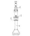
図1に、本発明の穿刺デバイスに使用できるランセットアッセンブリを斜視図にて、また、図2に、そのランセットアッセンブリの手前側半分を切除した状態で斜視図にて模式的に示す。図示したランセットアッセンブリ100は、ランセット101および保護カバー102から構成され、図示した態様では、ランセット101のランセットボディ104の周囲に保護カバーが配置されている状態を示している。
FIG. 1 is a perspective view schematically showing a lancet assembly that can be used in the puncture device of the present invention, and FIG. 2 is a perspective view schematically showing the front half of the lancet assembly cut away. The illustrated
図3に、本発明のランセットアッセンブリを構成するランセット101を斜視図にて、模式的に示す。ランセット101は、ランセットボディ104およびランセットキャップ106から構成される。図2から分かるように、所定箇所を穿刺する先端部を有する穿刺部材105が、ランセット内に埋設され、その先端部は、ランセットキャップ106内に、また、その他の部分がランセットボディ104内に存在する。
FIG. 3 is a perspective view schematically showing the
図4に、本発明のランセットアッセンブリを構成する保護カバー102を斜視図にて模式的に示す。図示した態様では、矢印Aで示す方向が、ランセットの発射方向、即ち、前向きである。尚、容易に理解できるように、本発明のランセットアッセンブリは、保護カバー102の前端部の開口部123からランセットのランセットボディの後方部分116を矢印Aと反対の方向に挿入することによって形成することができる。
FIG. 4 is a perspective view schematically showing the
このようなランセット101および保護カバー102から構成されるランセットアッセンブリは、図1に示した状態でランセットを発射するインジェクターアッセンブリに挿入してチャージされ、その後、図5に示すような穿刺部材105の先端部124を露出させた状態でランセットが発射された後、図6および図7に示すように、保護カバーが前方に移動した状態にできる。これらの図面に示した状態は、穿刺部材105の先端部が露出していることと、保護カバーの位置が前方に移動している点で、図1および図2に示す状態と異なるが、その他については実質的に相違しない。
The lancet assembly composed of the
ランセットボディ104とランセットキャップ106は、その間に位置する弱化部分108によって一体に結合されている。この弱化部分は、ランセットボディ104とランセットキャップ106とを穿刺部材の周囲で相対的に反対方向に回すことによって破壊することができる、即ち、いわゆるツイストオフすることができる。このようなランセットは、穿刺部材105を金型に予め挿入した状態でプラスチック材料をインサート成形することによって一体に形成するのが好ましく、弱化部分は、穿刺部材の周囲のプラスチック材料の厚さを薄くすることによって形成できる。
The
このツイストオフを容易ならしめるために、ランセットキャップ106は、指で挟んで容易に回転できるようにタブ要素110を有する。これは、例えば平坦な広がり部分であってよい。図示した態様では、そのような部分は、ランセットキャップ106の前方部分に設けられている。また、ランセットキャップ106の後端部には、当接要素112が設けられている。これは、ランセットキャップ本体から外向きに延在する突出部の形態、例えばフランジ形態であってよい。
In order to facilitate this twist-off, the
図1および図2から理解できるように、当接要素112は、保護カバー102の前端部の開口部123からランセットボディ104を挿入して、ランセットボディ104、特にその前方部分114の周囲に保護カバー102を配置する際に止めとして作用でき、保護カバー102の前端部が当接要素112に当接した状態となり、保護カバー102はそれ以上前進できない。
As can be seen from FIGS. 1 and 2, the
ランセットボディ104の後方部分116は、後述するようにインジェクターアッセンブリのプランジャーの対向するアームの間に位置でき、後方部分116に設けた突出部118がアームの内側に設けた凹部によって挟まれて把持されるようになっている。このように突出部118が把持されることによって、インジェクターアッセンブリ内でランセットがプランジャーに保持される。
As will be described later, the
また、ランセットボディの前方部分114はその後端部に突出部120を有し、また、前端部にも別の突出部122を有する。これらの突出部120および122は、保護カバー102をランセットボディ104の周囲に配置した場合、ランセット101に対して保護カバー102を位置決めする。このような位置決めによって、後述するように保護カバー102を移動するようにプッシャーによって加えられる力によって、保護カバー102とランセット101との間の位置関係が変わる、即ち、保護カバー102を前方に移動できるが、そのような力が作用しない場合には、位置関係が実質的に変化しないようにする。
Further, the
具体的には、突出部120は、ランセットボディ104の前方部分114の側面上で対向するように配置されており、突出部122についても同様である。対向する突出部120間の距離および突出部122間の距離は、図1および図2に示すように配置された場合に突出部が位置する箇所に対応する、保護カバーの内壁箇所の距離と実質的に同じであっても、あるいはその距離より若干大きく、プラスチック材料の弾性的変形を利用して、図1および図2に示す状態で上述の位置決めが可能になる。即ち、突出部120の外側輪郭は、保護カバーの内側輪郭と実質的に同じか、あるいは若干大きく、突出部122についても同様である。このような位置決めは、ランセットボディ104と保護カバー102とがプレスフィットの関係であると表現することができる。
Specifically, the protruding
保護カバー102が前方に移動して露出した穿刺部材の先端部124を完全に覆って、その後、その最先端126が保護カバー102の前端面から十分に後方に位置する図6および図7に示す状態になった時、突出部122は、保護カバー102の後方側面に設けた開口部125に嵌り込み、その結果、図6および図7に示す状態において、保護カバー102をランセットボディ104に対して後退させようとする力が作用した場合であっても、そのような嵌り込みによって後退が阻止されるように設計されている。即ち、保護カバー102の開口部125とランセットボディ104の突出部122は協働して保護カバー102の戻りを防止する。保護カバーの開口部の直前の壁部分128は、突出部122を乗り越えて前方に進むことができる必要があるので、突出部122は、図示するように前方に向かって広がるテーパー面130を有し、また、一旦乗り越えた保護カバー102の戻りを防止するために保護カバー102の側面に対して急峻な面、好ましくは実質的に垂直な面132を、テーパー面130に隣接して有する。このような突出部122は、戻り防止突起として機能する。
6 and 7 in which the
特に好ましい態様では、この突出部122は、図8に示すように、ランセットボディの前方部分114の前端部またはその近傍(例えば図示するように、前端部の少し後方)の側面から垂直方向に延び、その後、前方に折れ曲がって延びる形態(但し折れ曲がり部分は、湾曲状態であってもよい)、即ち、ランセットボディの側面から半「U」字状に前方に向かって突出する形態であるのが好ましい。特に、図8に示すように、突出部の根元付近の形状を保護カバーの後端部が、特にその開口部がタイトに受容できるように、あるいは後端部が嵌り込み、保護カバーの後端部がランセットボディの前端部と突出部122との間で挟み込まれるようにするのが好ましい。
In a particularly preferred embodiment, this
図9に、本発明の穿刺デバイスに使用できるインジェクターアッセンブリの外観を斜視図にて模式的に示し、図10は、図9に示したインジェクターアッセンブリの手前半分を切除して内部の様子が分かるようにした斜視図を模式的に示す。この状態は、ランセットの装填を待っている状態、即ち、待機状態である。 FIG. 9 schematically shows the appearance of an injector assembly that can be used in the puncture device of the present invention in a perspective view, and FIG. 10 shows that the front half of the injector assembly shown in FIG. A schematic perspective view is shown. This state is a state waiting for loading of the lancet, that is, a standby state.
本発明のインジェクターアッセンブリ200は、インジェクターボディ202ならびにその中に配置されたプランジャー204およびプッシャー206を有して成る。このインジェクターアッセンブリは、上述の保護カバーを有するランセットアッセンブリ100を装填して、穿刺部材の先端部が露出したランセットを発射できる。インジェクターボディ202は、キャップアッセンブリ208、1対のボディハーフ210および210’ならびにコッキング部材212から構成される。尚、簡単のため、組み合わされたボディハーフ210および210’をメインボディ220とも呼ぶ。インジェクターアッセンブリ200は、穿刺すべき所定箇所(例えば指先部分)をあてがう開口部214をその前方端部に有する。より詳しくは、キャップアッセンブリ208がその前方端部にて開口部214を規定する。尚、キャップアッセンブリ208は、既知の穿刺深さを変えることができる機構を有するのが望ましい。
The
上述のように穿刺深さ変えることができる機構自体は、例えばWO1997/004707号公報(日本国特許第3638958号、米国特許第5,730,753号に対応)から公知であり、この特許文献に開示の内容は、この引用によって本明細書に組み込まれる。例えば、ランセットを発射した時に、穿刺部材の先端部が突出しているランセットボディ104の前方への動きを瞬間的に止めて、その後、ランセットボディ104を後退させる、ランセットボディ104が衝突する要素(インジェクターボディ内に設けられ、ストッパーとして機能する要素)と開口部214との間の距離を変えることができるようにする。例えば、そのようなストッパーとして作用する要素をボディハーフの前端部に設け、その要素と開口部214との間の距離を変えることができるようにする。
A mechanism that can change the puncture depth as described above is known from, for example, WO 1997/004707 (corresponding to Japanese Patent No. 3638958 and US Pat. No. 5,730,753). The disclosure content is incorporated herein by this reference. For example, when the lancet is fired, the
例えば、キャップアッセンブリ208を、メインボディ220の前端部にネジ式で取り付けることができるようにすることによって距離を変えることができる。キャップアッセンブリ208をメインボディ220の周囲に設けたネジに沿って回転することによって、メインボディ220の長手方向でキャップアッセンブリ208の位置が変わり、その結果、上述の距離が変わる。
For example, the distance can be changed by allowing the
プランジャー204は、ランセットボディの後端部分116を保持し、穿刺部材105の先端部124が所定箇所を穿刺するように、穿刺部材105の先端部124が突出したランセットボディ104を前方に発射する機能を有する。尚、穿刺後は、穿刺部材105の先端部124が突出したランセットボディ104を後方に引き戻す機能をも有する。
The
プッシャー206は、穿刺後、引き戻された、ランセットボディ104の周囲に配置された保護カバー102を、ランセットボディ104に対して前方に押して、ランセットボディ104から前向きに突出する穿刺部材105の先端部124の周囲に位置するように移動させるように機能する。
The
本発明のインジェクターボディ202において、(例えばスナップフィットによって)相互に組み合わされ、内部に空間部を規定する対のボディハーフ210および210’の前方端部の周囲に、キャップアッセンブリ208が配置されている。このように規定された空間部には、上述のように、プランジャー204およびプッシャー208が配置されている。
In the
図11に、プランジャー204の斜視図を、また、図12に、プッシャー206の斜視図を模式的に示す。尚、プランジャー204は、上方ハーフ222および下方ハーフ224によって構成され、これらを(例えばスナップフィットによって)相互に組み合せた状態で示している。
FIG. 11 is a perspective view of the
プランジャー204は、内部に貫通した空間部を規定する円筒状の後方部分226およびその前方端部から前向きに延びる2本の対向する上方アーム228および下方アーム230を有して成る。尚、後半部分の内部に規定される空間の形状は、必ずしも円柱状である必要はなく、図示した態様では角柱状である。プランジャー204を規定するハーフ222および224は、実質的に同じ形態であるが、下方ハーフ224がカンチレバー232を有する点、および上側ハーフが突起524を有する点で異なる。
図13に、プランジャー204を構成する下方ハーフ224を模式的に斜視図にて示す。カンチレバー232は、その名の通り、片持ち梁の形態であり、その後端234は下側ハーフ224の後方部分の前方端部付近に一体に接続され、前端236はフリーであり、突起237が設けられている。この突起は、それを規定する後方のスロープ面235を有する。プランジャー204は、その全体がプラスチック製であるのが好ましく、そのため、カンチレバー232はその前端236、突起237またはそれらの近傍に下向きの力が作用すると、前端236が下方にずれて全体として湾曲した形状に弾性的に変形する。逆に、そのような力が除かれると、元の形状、図13に示す形状に戻る。
FIG. 13 is a perspective view schematically showing the
プランジャー204の上方アーム228および下方アーム230は、前方端部に凹部239および241をそれぞれ有する。これらの凹部の間に、ランセットボディ104の後方部分116に設けた突出部118の一部分が嵌り込む。即ち、このようなアーム、特にその凹部239および凹部241は、チャック要素を構成する。これらの凹部の形状は、突出部118の一部分が丁度嵌り込むようになっているのが好ましい、即ち、穿刺部材の長手方向に沿った断面に関して、凹部239および241と突出部118とが相補的であるのが好ましい。
これらのアームの凹部の後方に位置する、対向している内側面238および240は、ランセットボディ104の後方部分116の側面の一部分に対応するのが好ましい。即ち、内側面238および240は、ランセットボディ104の後方部分116の側面と相補的であるのが好ましく、このようにすると、アーム228と230が広がらない限り、後方部分116は、突出部118だけでなく、突出していない部分においても、アームの間で単に挟まれて保持されるだけではなく、何らかの力が作用する場合であっても、プランジャーに対してランセットボディの軸が実質的にずれるのが防止され、これらの内側面は、後方部分116の後向き移動のガイドとして作用する。従って、上述のチャック要素は、凹部の後方に位置し、ランセットボディの後方部分と相補的な内側面を更に有するのが好ましい。1つの態様では、プランジャーの前方部分、好ましくは上述の内側面の後方にペデスタルが存在する。特に好ましい態様では、内側面238および240がチャック要素を構成し、これらの間に形成される空間部の最深部にペデスタルが存在する。
Opposing
尚、図示した態様では、内側面238および240の後方には凹部242(図13参照)が設けられている。この凹部242には、ランセットボディ104の後端に設けた突出部131の少なくとも一部分がぴったりと嵌り込むようになっている。即ち、これらの凹部242がランセットボディの後端部を受け止めるペデスタル(または台座)としての役割を果たす。図示した態様では、ランセットボディ104の後端面に十字形の突出部131が設けられ、その一部分が凹部242に嵌り込むように構成されている。このようにプランジャーのアームとランセットボディの端部に相互に係合する手段(例えば凹部と凸部または凸部と凹部)を設けると、ランセットがその穿刺部材の周囲でプランジャーに対して相対的に回転することが防止される。
In the illustrated embodiment, a recess 242 (see FIG. 13) is provided behind the inner side surfaces 238 and 240. At least a part of the
尚、ランセットアッセンブリの装填に際しては、図10にて矢印Fで示すように、あるいは図11にて矢印Bで示す方向にランセットボディ104の後方部分116がインジェクターアッセンブリ200の開口部214から内部に挿入され、その中に配置されたプランジャー204に向かって移動してくる。この時、挿入されてくるランセットボディ116の後端部は、アーム228の先端部264とアーム230の前端部266との間を通過し、ランセットボディ116の後方部分116の一部分は、内側面238と240との間に入り込み、ランセットボディ116の突出部118が、先端部264と266に当接する。容易に理解できるように、プランジャーは、上述のように対向する2つのアームを、好ましくは全体としてU字形状のアームを有してよいが、別の態様では、ランセットボディの後方部分を適当に把持できる限り、2より多い数のアームを有してよい。従って、プランジャーは少なくとも2つのアームを有して成る。
When the lancet assembly is loaded, the
突出部118は、例えばリムまたはフランジの形態であって、ランセットボディ104の側面から突出した形態であってよい。1つの態様では、図3に示すように、突出部108は、ランセットボディ104の側面から突出部の最外輪郭部に向かって延在するスロープ面140(図示した態様では円錐台の側面に相当)および142によって規定されている。他方、アーム228および230の先端部264および先端部266は、図11に示すように、ランセットの発射方向に向かって広がる曲面268および270を有し、好ましくは、その曲面ような曲面は、スロープ面140と相補的である。
The
従って、上述のようにランセットボディ104が挿入されて、突出部118がアームの先端部264および先端部266に当接する場合、ランセットの発射方向に向かって広がるスロープ面140が、ランセットの発射方向に向かって広がるスロープ面268および270を押すので、プランジャーのアームの先端部264および266を上向きおよび下向きに移動させようとする力がそれぞれ作用する。
Therefore, when the
アーム228およびアーム230は、その後方端部にてプランジャー204の後方部分226と一体になっているので、上述のような力が作用すると、(矢印Cおよび矢印Dで示す方向に)アームの先端部264および266は移動しようとしてアーム228およびアーム230が弾性的に若干湾曲する(即ち、外向きに広がる)。その結果、先端部264と266との間が広がり、ランセットボディ104の突出部118が、内側面238および240によるランセットボディ104の後方部分116の後方向への移動に対するガイドに助長されながら、アームの先端部の間を通過して、先端部の直ぐ後に位置する凹部239および凹部241に嵌り込む。
Since the
突出部118が凹部239および241に嵌り込んだ後は、これらの形状が相補的であるので、アーム228および230に作用する力は実質的に存在しなくなり、その結果、弾性的に湾曲したアームは元の形状に戻り、アーム228および230によるランセットの把持が完結する。尚、インジェクターアッセンブリ内において、上述のようなアームの一時的な弾性的な湾曲を可能にし、また、把持後は、弾性的な変形を阻止するために、インジェクターボディ、詳しくはメインボディの内壁は、アームの先端部264および266の上側形状および下側形状に対応する形状を有する凹部を設けている。そして、そのような凹部が存在しない領域では、アームの先端部は上または下に移動することができず、他方、そのような凹部が存在する領域では、先端部の上側形状部分および下側形状部分がその凹部に嵌り込む結果、先端部が上または下方向に移動して(即ち、インジェクターアッセンブリの内壁に向かう方向に広がり)弾性的な湾曲が可能となるようになっている。
After the
上述のようなプランジャー204に、図12示すようなプッシャー206を組み合わせて用いる。プッシャー206は、ロッド状部分244、およびその前端部から前向きに延びるアーム246およびアーム248から構成される前方部分250を有して成る。アーム246および248は全体としてU字形状の形態であり、その根元付近に凹部245が形成され、凹部の底247とロッド状部分244の側面とを接続するスロープ面249が設けられている。
A
尚、図示したプッシャー206は、その表裏(または上下)を反転させた後、図11に示したプランジャーの上側ハーフ222と下側ハーフ224との間に配置し、その後、これらのハーフを組み合わせてプランジャー204を構成することによって、プランジャー204と操作可能に組み合わされる。プッシャー206の前方部分250に隣接する、ロッド状部分244は、その前方端部から後方に向かって、断面が比較的長い距離にわたって矩形で一定形状であり(部分252)、その後、断面の矩形形状が徐々に薄く小さくなり(部分254)、その後、再び、厚くなっている(部分256)。
The
断面が矩形で一定形状である部分(部分252)は、プランジャーの後方部分226によって規定される空間260内を前後に移動、好ましくは摺動できるようになっている。空間260内でプッシャー260が前方に移動すると、アーム248および246の付け根部分に規定された凹部245にプランジャー204の下側アームに設けたカンチレバー232の前端部236の突起237が嵌り込み、その後、移動を続けると、凹部245に隣接するスロープ面249がプランジャーのスロープ面235に当接する。
A portion (portion 252) having a rectangular cross section and a fixed shape can be moved back and forth in the
移動を更に続けると、スロープ面235とスロープ面249が相対的に反対方向に移動することになる一方で、プッシャーの部分252の上下方向への移動は、プランジャー204の上側アーム228および下側アーム230の後方部分226に近い側の部分によって制限されているので、結果的に、プッシャー206のスロープ面249がカンチレバー232の突起237を下向きに押すことになる。その結果、カンチレバー232が下向きに弾性的に湾曲する。即ち、カンチレバーは、下向きに湾曲したバイアス状態となり、プッシャーの部分253を上向きに押している状態となる。
If the movement is further continued, the
この状態で、プッシャーの移動を更に継続すると、プッシャー206のスロープ面249の更に後方に設けた凹部262が、プランジャー204の突起237に近づき、その後、カンチレバーの弾性故に突起237が凹部262に嵌り込むように構成されている。突起237が嵌り込んだ状態では、カンチレバーは、それには何らの力も作用していない状態となり、図13に示すような元も形状に戻っている。
In this state, if the movement of the pusher is further continued, the
上述のようなカンチレバーの突起の動作を利用することによって、プランジャー204およびプッシャー208は、ランセットアッセンブリをインジェクターアッセンブリに装填した後、所定箇所の穿刺が終了するまでは、相互に独立して移動可能であるが、穿刺後に保護カバーをランセットボディの周囲で前方に移動させるに際して、プッシャーがプランジャーを拘束してプランジャーの移動を阻止するように構成することができる。即ち、下向きに弾性的に湾曲したカンチレバーの端部がインジェクターボディ、詳しくはメインボディの内壁に当接し、カンチレバーの端部と内壁との間の摩擦力によって、プランジャー204に対して前向きの力が作用する場合であっても、プランジャー204がインジェクターボディに対して前方に移動せずに、固定した状態で保持できる。
The
特に好ましい態様では、インジェクターボディ、詳しくはメインボディの内側に、下向きに湾曲したカンチレバーの端部の直ぐ前方に位置するストッパー、例えば突起を設ける。このようにストッパーを設けることは、カンチレバーの端部と内壁との間の摩擦力だけでは、プランジャーの移動防止に不十分である場合には、特に有効であり、プランジャー204の移動を確実に防止できる。好ましくは、カンチレバーの前端部の裏側(即ち、下側にも)にも、突起237と同様の突起を設けるのが好ましく、そのような突起とストッパーとの係合が容易かつ確実になる。
In a particularly preferred embodiment, a stopper, such as a protrusion, is provided on the inside of the injector body, specifically the main body, located immediately in front of the end of the cantilever that curves downward. Providing the stopper in this way is particularly effective when the frictional force between the end of the cantilever and the inner wall is insufficient to prevent the plunger from moving, and ensures that the
本発明の穿刺デバイスは、上述の本発明のランセットアッセンブリを上述の本発明のインジェクターアッセンブリに装填することによって構成される。従って、装填前の状態にある、本発明のランセットアッセンブリおよび上述の本発明のインジェクターアッセンブリ、即ち、これらが別々に存在して、組み合わされていない状態にある、本発明のランセットアッセンブリおよび上述の本発明のインジェクターアッセンブリは、穿刺デバイスのキットを構成する。 The puncture device of the present invention is configured by loading the above-described lancet assembly of the present invention into the above-described injector assembly of the present invention. Accordingly, the lancet assembly of the present invention and the above-described injector assembly of the present invention in a state before loading, that is, the lancet assembly of the present invention and the above-described book in a state where they exist separately and are not combined. The injector assembly of the invention constitutes a puncture device kit.
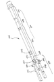
図10および図14〜図25を参照して、上述のランセットアッセンブリおよびインジェクターアッセンブリを用いて本発明の穿刺デバイスを構成して、所定箇所を穿刺し、その後、使用済みのランセットをインジェクターアッセンブリから取り出す様子を順に説明する。 Referring to FIGS. 10 and 14 to 25, the lancet assembly and the injector assembly described above are used to constitute the puncture device of the present invention to puncture a predetermined location, and then the used lancet is taken out from the injector assembly. A state is demonstrated in order.
最初に、図10に示す待機状態にあるインジェクターアッセンブリ200に、ランセットアッセンブリ100を装填する。具体的には、図10の矢印Fで示すように、インジェクターアッセンブリ200の前端面の開口部214からランセットボディ104の後方部分116を挿入する。尚、保護カバー102がインジェクターボディの前方部分、特にその開口部214を容易に通過できるが、その内側で回転できない程度に、発射方向に対して垂直な保護カバーの断面の外側輪郭は、発射方向に対して垂直なインジェクターボディの前方部分、特にその開口部214付近の断面の内壁の輪郭と若干の間隙を隔てて相補的であるのが好ましく、そのようすることによって、インジェクターボディに対する保護カバー、従って、ランセットアッセンブリ100の位置決め(特に発射方向の周囲に関する位置決め)が容易になる。
First, the
上述のように挿入を続けると、後方部分116は、図14に示すように、プランジャーのアーム228の先端部264とアーム230の前端部266との間を、そして、凹部239と凹部241との間も通過し、後方部分116の側面と相補的な形状を有するアームの内側面238および249の間で摺動する。そして、後方部分116に設けた突出部118がアームの先端部264および266に当接する。
Continuing the insertion as described above, the
上述のように先端部264および266は、ランセットの発射(または射出)方向に向かって広がるスロープ面268および270を有し、スロープ面の形状は、突出部118のスロープ面140と相補的であるので、当接後に更にランセットアッセンブリを後方に移動させようとすると、図11において矢印CおよびDにて示すように、アーム228および230は外側に向かって広がろうとする。この場合、インジェクターボディ、詳しくはメインボディの内壁部をアームの先端部の最外部502および504が内壁部に対して摺動するように設計していると、そのように広がろうとする作用は抑制されるが、内壁部に凹部506および508を設けておくと、先端部が摺動して後退し、その最外部502および504が凹部506および508に嵌り込んだ時のみ、凹部の深さ分だけアームが外向きに広がろうとする。
As described above, the
この広がりによってアームの先端部の最内部510と512との間の距離を、ランセットボディの後方部分116に設けた突出部118がその間を通過できるようにすることによって、後方部分116は、更に後方に移動でき、その結果、図15に示すように、後方部分116に設けた突出部118がアーム先端部の凹部239および241の間に嵌り込む。尚、凹部239と241を規定する面を、突出部118を規定する面と相補的にすることによって、突出部118の凹部239と241との間への嵌り込みは、緊密なものとなる。そして、図15に示すように、インジェクターボディ、詳しくはメインボディの内壁部に設けた凹部506および508の長さは発射方向に対して短いものであるので、その後、ランセットを後方に押す力が作用しても、アーム228および230は外側に広がることはなく、後退しようとするだけであり、従って、ランセットアッセンブリ100は、プランジャーのアーム228および230によってしっかり把持されている。
This extension allows the
その後、ランセットアッセンブリを後退させるように力が作用すると、プランジャーは後退することができる。ところで、インジェクターアッセンブリ200には、ランセットを発射する引き金として作用する、レバー状のトリガー部材514が設けられている。図示した態様では、点516を支点として移動(軸回転)可能であり、前方の端部分542とその下方のプレート518との間には圧縮状態でバネ520(簡単のため、矢印で示す)が設けられている。トリガー部材は、支点516の回りでシーソー状に運動可能であり、前方端部分542にはバネ520によって上向きの力が作用しているが、インジェクターハウジングによってトリガー部材の前方端部分の上向きの動きは制限されている。
Thereafter, when a force is applied to retract the lancet assembly, the plunger can retract. Incidentally, the
上述のように、プランジャーが更に後退すると、それに一体に設けた突起524も一緒に後退する。この突起524は、その上部がトリガー部材514の後方端部分526に接触し、その後、後方部分526に上向きの力を作用させながら(従って、バネ520を圧縮しながら)、更に後退する。そして、突起524が、トリガー部材514の後端部526を通過すると、トリガー部材514と突起524との接触関係は解除され、圧縮されたバネ520は再び延び、トリガー部材514も元の状態(図14の状態)に戻る。その結果、トリガー部材514の後端が下がり、突起524の前方への移動を阻止する。このように、突起524が後端部526を通過して、トリガー部材514が丁度元の状態に戻った様子を図16に示す。この状態が、ランセットアッセンブリ100の装填(即ち、チャージ)が完了した状態である。
As described above, when the plunger is further retracted, the
尚、メインボディ220の内部では、プランジャーの周囲にて突起524とのメインボディの後端部530との間に、バネS1(矢印で示す)が配置されている。このバネS1は圧縮可能である。上述のように、ランセットアッセンブリを挿入するに際しては、バネS1が図10に示す状態から図16に示す状態まで圧縮される。図10の状態に比べて図16状態では、バネS1の長さ(即ち、突起524と後端部530との距離)が短くなっている。上述のように、トリガー部材514の後端部526が、突起524の前方への移動、従って、プランジャー204の前方への移動を阻止しているので、バネS1は圧縮状態で保持されている。
In the
この状態からトリガー部材514の後端部526が上方に移動すると、即ち、トリガー部材の前方端部542を下方に押し込んでバネ520を圧縮すると、トリガー部材514の後端部526は上方にずれ、その結果、突起524の前方への移動を阻止できないことになり、上述のように圧縮状態で保持されているバネS1は一気に伸長し、それによって、突起524は、従って、プランジャーは、従って、プランジャーに保持されたランセットは前方に移動する。後述のように穿刺部材の先端部を露出させた状態で、上述のようなトリガー部材514の操作を実施して圧縮状態のバネS1を拘束しているもの無くすので、バネS1は瞬間的に伸び、ランセットが発射され、インジェクターアッセンブリの開口部214に押し当てた所定の箇所を穿刺できる。
When the
また、コッキング部材212の内部では、プランジャーの周囲にて、コッキング部材212の前端部532とプランジャーの後端部に取り付けた仕切部材534との間にバネS2が配置され、また、コッキング部材212の後端部536と仕切部材534との間にバネS3が配置されている。尚、仕切部材534は、プランジャーの後端部に固定された状態で、コッキング部材212内をその内壁に沿って前後に摺動できるようになっている。よって、仕切部材534の位置に応じてバネS2およびバネS3は圧縮される程度が変化する。
Inside the cocking
バネS2は、ランセットが発射されると、プランジャー204の後端部が前に移動するので瞬間的に圧縮されるが、その後、直ちに元の長さに向かって伸びる。従って、バネS2は、発射されたランセットを後方に引き戻すように作用する。バネS3は、後述するように、使用済みのランセットから突出している穿刺部材の先端部の周囲に保護カバーを移動させるに際して、プッシャーを前方に移動させるために力を加えて前方に移動したプッシュバー213を後に戻す機能を有する。即ち、プッシュスプリングとして機能する。
When the lancet is fired, the spring S2 is instantaneously compressed because the rear end of the
尚、容易に理解できるように、図示したインジェクターアッセンブリ200において、コッキング部材212に力を加えてこれを他の部分に対して後退させると、コッキング部材212の前端部がプランジャーの後端部に設けた仕切部材534を後退させることになる。それに伴って、プランジャーが後退し、その結果、プランジャーの突起524がトリガー部材514の後端部526を越えて後方に移動できる。その状態で、コッキング部材212に加える力を解放すると、プランジャーの突起524がトリガー部材514の後端部526の後側に、前向きの力を作用させながら、当接した状態となり、プランジャーに関しては、ランセットを発射できる状態となる。即ち、コッキング状態(あたかも銃を用いる場合にコッキングした状態)となり、それ故、部材212をコッキング部材と便宜的に呼ぶ。
As can be easily understood, in the illustrated
上述のように、図16のようにランセットアッセンブリ100のチャージが完了した状態では、(インジェクターボディ202を基準として)プランジャー204は図10に示す待機状態から後方に移動しているので、プランジャーの後端部が後方に移動し、従って、バネS2は相対的に伸びた状態であり、バネS3は相対的に縮んだ状態である。
As described above, in the state where the charging of the
尚、上述のようにチャージが完了した状態になった時に、印を付した、プランジャーの一部分がインジェクターボディハーフに設けた窓としての開口部から見えるようにしておくと、チャージ完了をランセットアッセンブリの使用者が目視的に確認できる。図示した態様では、突起524が存在する箇所の側方にインディケータ538を設ける。これには例えば、目立つ色(例えば緑色)を付け、チャージ完了状態の時にインディケータ538の側方に対応する、ボディハーフの壁に開口部540を設ける(図9参照)。このようにすると、チャージ完了時には、開口部540からそのような色が見え、チャージの完了を確認できる。
When the charging is completed as described above, if a part of the plunger marked is visible from the opening as a window provided in the injector body half, the charging completion is confirmed. Can be visually confirmed. In the illustrated embodiment, an indicator 538 is provided on the side of the portion where the
チャージが完了すると、次に、ランセットキャップを除去する。これは、図16に示すように、プランジャーに把持されたランセットを有するインジェクターアッセンブリに対して、ランセットキャップを発射方向の回りで回転する、即ち、図16に矢印Gで示すようにツイストすることによって、ランセットの弱化部分108を破壊し、その後、ランセットキャップ106を前方に引っ張ることによって実施する。ランセットキャップを除去した状態を図17に示す。
When charging is completed, the lancet cap is then removed. This means that for an injector assembly having a lancet gripped by a plunger as shown in FIG. 16, the lancet cap is rotated around the firing direction, ie twisted as shown by arrow G in FIG. By breaking the weakened
尚、上述のように、ランセットキャップをツイストするに際して、ランセットボディが一緒に回転するのを防止するために、ランセットボディの後方部分は、上述のように突出部131を設け、この突出部の少なくとも一部分がプランジャーの内側面の後方に設けた凹部に嵌り込むようにしておく。この突出部は、穿刺部材を軸とする軸対称でない形状であるかぎり、いずれの適当な形状であってもよい。例えば後方部分の端面にて「I(アルファベットの文字「アイ」)」字状に(即ち、直線状)に突出する形状、あるいは「X」字状(即ち、十字状)に突出する形状であってもよい。図3に示す態様では、「X」字状の突出部131を設け、プランジャーにはその突出部の一部分が嵌り込む凹部242が設けられている。
As described above, when twisting the lancet cap, in order to prevent the lancet body from rotating together, the rear portion of the lancet body is provided with the protruding
次に、インジェクターボディの開口部214に穿刺すべき所定の箇所、例えば指先をあてがう。その状態で、インジェクターボディの側面上方部に、プレスボタンとして露出しているトリガー部材514の前方端部分542の一部分を矢印Jで示すように下向きに押し込むと、トリガー部材514の後方端部526が上向きに移動し、その結果、後方端部526とプランジャーの突起524との当接関係が解除され、圧縮されていたバネS1が一気に伸びる。それによって、穿刺部材105の先端部124が露出したランセットボディ104が一瞬のうちに前方に移動して、インジェクターアッセンブリの開口部214から突出して所定箇所を穿刺した後、逆向きに移動し、即ち、後退して、プランジャーは待機状態と同じ位置に戻る。
Next, a predetermined portion to be punctured, for example, a fingertip, is applied to the
図18は、穿刺部材の先端部124が最も前方に移動した状態(即ち、穿刺している状態)を示し、図19は、その後、プランジャーが戻りきった状態を示す。この後、使用済みのランセットを廃棄するためにインジェクターアッセンブリから外すプロセスに移る。
18 shows a state in which the
図19の状態から、図20に示すように、最初に、矢印Hで示すように、プッシュバー213に前向きの力を加えてプッシャー206を前方に移動させる。プッシャー206の前方部分250の両アーム246および248の先端部は、保護カバー102の後端部150(図4参照)に当接する。この当接を容易ならしめるために、保護カバー102は、その後端部において側方に突出する突出部152を有するのが好ましい。このように当接した状態を図20に示す。このようにプッシャー206を移動するのを助長するため、プッシャー206は、そのアームの側方に突出部280を有し、この突出部280が、ランセットボディの内壁に設けたチャンネル内を前後に移動できるようになっている。
From the state of FIG. 19, as shown in FIG. 20, first, as indicated by an arrow H, a forward force is applied to the
図20の状態から、プッシュバー213を更に前方に押してプッシャー206を更に前方に移動させると、そのアーム246および248によって保護カバー102は前方に移動し、プッシャーのロッド状部分244がプランジャー204の後方部分226内の空間260内を摺動する。そして、プッシャーのアームの付け根部分に設けた凹部247およびその後のスロープ面249がプランジャーのカンチレバー232のスロープ面235に接触して、図20に示すように、カンチレバー232が下向きに湾曲し、カンチレバーの前方端部がプランジャーの下側から突出する。尚、上述のように、カンチレバーの前方端部の下側にも、突起237と同様の図示した突起243を設けるのが好ましい。
When the
このように湾曲した前端236または突起243は、インジェクターボディ、詳しくはメインボディの内壁に当接してブレーキとして機能し、プランジャー204に前向きの力が作用した場合であっても、プランジャーの前向きの移動を防止する。好ましい態様では、図示するように、インジェクターボディの内壁にストッパーとしての突出部550を設ける。その場合、湾曲した前端236または突起243は、突出部550に容易に当接でき、その後、プランジャーはそれ以上前方に移動できなくなる。図21では、前端236がそのようにストッパー550に当接した状態を示す。
The curved
上述のようにプランジャー204の前方の移動が防止されると、ランセットボディ104の前方への移動が防止され、他方、プッシュバー213を更に前方に押すと、保護カバー102の後端に前向きの力が作用する。その結果、保護カバー102のみが前方に十分に移動して、突出している穿刺部材の先端部の周囲に移動し、そして、穿刺部材の最先端部126が保護カバー128の前端面から十分に後方に位置するようになる。その状態を図22に示す。この状態では、保護カバーとランセットボディ104の関係は、図6または図7に示す状態と実質的に同じである。即ち、保護カバー102が十分に前方に移動して、保護カバーの後端部に設けた開口部124内にランセットボディの突出部122が嵌り込んだ状態となっている。従って、保護カバー102は、この状態から前へも後へも実質的に移動できないようになっている。図から理解できるように、プランジャーのアーム228および230の先端部の最外部502および504は、インジェクターボディ、詳しくはメインボディの内壁と隣接状態にあるため、アーム228および230は図示した状態から更に外向きに広がることができない。
As described above, when the
その後、プッシュバー213を更に前方に押すと、プッシャー206がカンチレバー232を湾曲させた状態で、プランジャー204に対して前方に移動し、その後、プッシャーの開口部262にカンチレバー232の前端部の突起236が嵌り込み、カンチレバー232が元の状態に戻る(即ち、湾曲状態が解消する)。この時、カンチレバーの前端部のストッパーとしての機能は無くなり、従って、プランジャーも前方に移動可能となる。従って、プッシャー206によってプランジャーが前方に移動すると、プランジャーのアームの前端部264および266がインジェクターボディの内壁に設けた凹部560および562に達すると、アーム228および230は外向きに広がることができる。この時、プッシャー206が保護カバー102の後端を既に前向きに押しているので、ランセットボディには前向きの力が作用するためアーム228および230が開き、その結果、ランセットボディ、特にその突出部118がアームの凹部239および241から解放され、その後、前向きに押し出される。
Thereafter, when the
図23は、丁度、プランジャーのアームの前端部264および266がインジェクターボディの内壁に設けた凹部560および562に達して、アーム228および230は外向きに広がった状態を示し、図24は、その後、ランセットボディの後方部分116がアームの凹部239および241から解放された状態を示す。
FIG. 23 shows the state in which the front ends 264 and 266 of the plunger arm have just reached the
容易に理解できるように、プッシャーは、上述のように対向する2つのアームを、好ましくは(図示するように)全体としてU字形状のアームを有してよいが、別の態様では、保護キャップの後端部を適当に押すことができる限り、2より多い数のアームを有してよい。従って、プッシャーは少なくとも2つのアームを有して成る。 As can be readily appreciated, the pusher may have two opposing arms as described above, preferably a U-shaped arm as a whole (as shown), but in another aspect, a protective cap There may be more than two arms as long as the rear end can be pushed properly. The pusher therefore comprises at least two arms.
尚、図22の状態において、ストッパー550が機能しているので、プランジャー204は前方に移動できず、従って、プッシャーのアーム246および248が後端に当接している保護カバー102も前方に移動できない。この状態で、プッシャー206のみを前に少しだけ移動できるように、プッシャー204の凹部262の位置(従って、凹部247と凹部262との間の距離)を設定しておくと、プランジャーのアーム228および230の前端部がランセットボディの突出部118を解放する前に、プッシャー206のアーム246および248が多少湾曲状態となる。その直後、プランジャーのアームの前端部264および266が凹部560および562に達すると、アーム228および230が外向きに広がると実質的に同時にプッシャーのアーム246および248が元の形状に戻ろうとして、突出部118が解放されたランセットボディに前向きに移動する力を瞬間的に与え、その結果、保護カバーが穿刺部材の周囲に配置されたランセットがインジェクターアッセンブリの開口部214から飛び出す。その様子を図25に示している。尚、プッシュバー213は、それに作用する力を解放した状態であり、バネS3の作用によって元の状態(即ち、待機状態)に戻っている。
In the state shown in FIG. 22, since the stopper 550 is functioning, the
飛び出した、あるいは上述のように解放されたランセットでは、保護カバーが穿刺部材の周囲に配置され、また、穿刺部材の最先端部が保護カバー102の前端面から十分奥に位置するので、使用済みのランセットを取り扱う場合であっても、穿刺後の穿刺部材の先端部に接触する可能性が大きく減る。
In the lancet that has been popped out or released as described above, the protective cover is disposed around the puncture member, and the most advanced part of the puncture member is located sufficiently deep from the front end surface of the
このように、穿刺後にランセットをインジェクターアッセンブリから取り外す操作は、本発明のランセットアッセンブリおよびインジェクターアッセンブリを用いる穿刺デバイスを用いる場合、上述のように、ランセットを直接取り扱うことなく、単に、プッシュバー213を前方に押し込むことによって、保護カバーを突出している穿刺部材の先端部に配置することによって容易に実施できる。
As described above, the operation of removing the lancet from the injector assembly after puncturing is performed by simply moving the
尚、上述の説明においては、ランセットアッセンブリのチャージは、ランセットアッセンブリを後方に押し込むことによって完了させたが、別の態様では、ランセットボディの後方部分をプランジャーの対向するアームに把持させた後、コッキング部材213をランセットボディ220に対して後方に引いて、プランジャーの突起524をトリガー部材514の後端部526の後方に位置させることによっても実施することができる。
In the above description, the charging of the lancet assembly is completed by pushing the lancet assembly backward, but in another aspect, after the rear part of the lancet body is gripped by the opposing arm of the plunger, It can also be implemented by pulling the cocking
上述の説明から容易に理解できるように、本発明のランセットアッセンブリおよびインジェクターアッセンブリを用いて穿刺デバイスを構成して穿刺操作を実施する場合、ランセットアッセンブリのインジェクターアッセンブリへの装填から使用済みのランセットのインジェクターアッセンブリからの排出までを、実質的には次のような5つのステップで実施できる: As can be easily understood from the above description, when a puncture device is configured using the lancet assembly and the injector assembly of the present invention to perform a puncture operation, the injector of the used lancet from the loading of the lancet assembly into the injector assembly is used. The discharge from the assembly can be carried out in substantially five steps as follows:
ステップ1(ランセットアッセンブリの装填)
ランセットアッセンブリ100をインジェクターアッセンブリ200の開口部214からその内部に挿入して押し込む(図10の状態から図16の状態となるまでのステップ)。それによって、プランジャー204のアーム228および230が、ランセットボディの後方部分116を把持すると共に、バネ520によって作用する力に抗しながらトリガー部材514の後方部分を徐々に押し上げながら後方に移動する。そして、プランジャーの突起524がトリガー部材514の後方端部分526の直下を通過すると、バネ520が伸びることにより後方端部分526が下向きに移動する。その結果、突起524がトリガー部材514の後方端部分526に当接した状態となり、ランセットアッセンブリの装填(チャージ)が終了し、穿刺準備が完了した状態となる。尚、当接状態に達する時、トリガー部材の後方端部がプランジャーの上方アームに衝突し、その結果、軽いクリック音および衝撃を感じることができるので、装填終了を容易に検知できる。Step 1 (Loading the lancet assembly)
The
ステップ2(ランセットキャップの除去)
インジェクターアッセンブリの前端から突出しているランセットキャップ106をひねって弱化部分108を破壊し、その後、ランセットキャップ106を引き抜いて除去し、ランセットボディの前端部から穿刺部材の先端部を突出させる。即ち、図17の状態とする。Step 2 (Removing the lancet cap)
The weakened
ステップ3(ランセットの発射)
図17にて矢印Jで示すようにプレスボタン542を押し込んで、穿刺部材の先端部124が突出した状態のランセット101を所定部位に向かって発射する。発射されたランセット101は、開口部214にあてがった所定部位を穿刺し(図18の状態)、その後、後退する(図19の状態)。Step 3 (Launch of lancet)
As shown by an arrow J in FIG. 17, the press button 542 is pushed in, and the
ステップ4(使用済みランセットの排出)
その後、プッシュバー213を前方に押し込んで(図20の状態)、プッシャー206によって保護カバー102を前方に移動させ(図21の状態)、ランセットボディの前端部から突出している穿刺部材の先端部124の周囲に配置し(図22の状態)、その後、プッシャーを更に押し込んでランセット101をインジェクターアッセンブリの開口部214から排出する(図24および図25の状態)。排出されたランセットは適切に処分できる。Step 4 (Draining the used lancet)
Thereafter, the
尚、米国特許明細書第5385571号公報に記載のランセットを用いて穿刺操作を実施する場合、ランセットのインジェクターへの装填から使用済みのランセットのインジェクターからの排出まで、実質的には次のような9つのステップが必要となる: When performing a puncturing operation using the lancet described in US Pat. No. 5,385,571, from the loading of the lancet into the injector to the discharging of the used lancet, the following is substantially the following. Nine steps are required:
(1)インジェクターからインジェクターキャップを外す。
(2)ランセットをインジェクターに嵌め込む。
(3)嵌め込まれたランセットからランセットキャップを除去する。
(4)上述のように外したインジェクターキャップをインジェクターに被せる。
(5)インジェクターをコッキングしてランセットが装填された状態とする。
(6)トリガーボタンを押して、ランセットを発射する。
(7)インジェクターキャップを外す。
(8)露出した状態の穿刺部材の先端部にランセットキャップを嵌めて先端部を隔離する。
(9)ランセットをインジェクターから外し、使用済みランセットを処分する。(1) Remove the injector cap from the injector.
(2) Insert the lancet into the injector.
(3) Remove the lancet cap from the fitted lancet.
(4) Put the injector cap removed as described above over the injector.
(5) Cocking the injector so that the lancet is loaded.
(6) Press the trigger button to fire the lancet.
(7) Remove the injector cap.
(8) A lancet cap is fitted to the tip of the exposed puncture member to isolate the tip.
(9) Remove the lancet from the injector and dispose of the used lancet.
比較すると容易に理解できるように、本発明のランセットアッセンブリおよびインジェクターアッセンブリを用いて穿刺デバイスを構成して穿刺操作を実施する場合、穿刺のステップ数が大きく減り、穿刺操作が簡便になるという利点もある。 As can be easily understood by comparison, when the puncture device is configured using the lancet assembly and the injector assembly of the present invention and the puncture operation is performed, there is an advantage that the number of puncture steps is greatly reduced and the puncture operation is simplified. is there.
上述の記載から明らかなように、本発明のランセットアッセンブリおよびインジェクターアッセンブリは、より安全に採血できる穿刺デバイスを提供する。 As is clear from the above description, the lancet assembly and injector assembly of the present invention provide a puncture device that can collect blood more safely.
本願は、日本国特許出願:特願2005−231649(出願日:2005年8月10日、発明の名称:穿刺デバイスならびにそれを構成するランセットアッセンブリおよびインジェクターアッセンブリ)に基づく優先権を主張し、これらの特許出願の内容は、これらを参照することによって本願明細書に組み込まれる。 The present application claims priority based on Japanese patent application: Japanese Patent Application No. 2005-231649 (filing date: August 10, 2005, title of invention: puncture device and lancet assembly and injector assembly constituting the device). The contents of these patent applications are incorporated herein by reference.
Claims (19)
(b)インジェクターボディならびにその中に配置されたプランジャーおよびプッシャーを有して成り、ランセットを発射するインジェクターアッセンブリ
を有して成る穿刺デバイスであって、
(1)ランセットは、ランセットボディ、ランセットキャップおよび穿刺部材を有して成り、穿刺部材はランセットボディおよびランセットキャップにまたがってこれらの中に存在し、穿刺部材の先端部はランセットキャップによって包囲され、
(2)保護カバーは、ランセットボディの周囲に配置され、穿刺後、ランセットボディから前向きに突出する穿刺部材の先端部の周囲に位置するように移動でき、
(3)プランジャーは、ランセットボディの後端部分を保持し、突出した穿刺部材の先端部が所定箇所を穿刺するようにランセットボディを発射し、
(4)プッシャーは、穿刺後、ランセットボディの周囲に配置された保護カバーを前方に押して、ランセットボディから前向きに突出する穿刺部材の先端部の周囲に位置するように移動させる
ことを特徴とする穿刺デバイス。(A) a lancet assembly comprising a lancet and a protective cover; and (b) a puncture comprising an injector body and a plunger and pusher disposed therein, the injector assembly firing the lancet. A device,
(1) The lancet has a lancet body, a lancet cap, and a puncture member, the puncture member is present in the lancet body and the lancet cap, and the tip of the puncture member is surrounded by the lancet cap.
(2) The protective cover is arranged around the lancet body and can move so as to be located around the tip of the puncture member protruding forward from the lancet body after puncturing,
(3) The plunger holds the rear end portion of the lancet body, and fires the lancet body so that the protruding tip of the puncture member punctures a predetermined location.
(4) After the puncture, the pusher pushes forward the protective cover arranged around the lancet body, and moves the pusher so as to be positioned around the tip of the puncture member protruding forward from the lancet body. Puncture device.
ことを特徴とする請求項1に記載の穿刺デバイス。Make sure that the plunger is prevented from moving forward when the pusher is moved forward with respect to the plunger in order for the pusher to push forward the protective cover placed around the lancet body. The puncture device according to claim 1, characterized in that:
アームの前端部は、ランセットボディの後方部分を把持するチャック要素を構成する
ことを特徴とする請求項1または2に記載の穿刺デバイス。The plunger comprises a generally cylindrical rear portion and a front portion having at least two arms extending forward from a front end of the rear portion;
The puncture device according to claim 1 or 2, wherein the front end portion of the arm constitutes a chuck element that grips a rear portion of the lancet body.
アームの前端部は、保護カバーの後端を押して保護カバーを前方に移動させることができ、
ロッド状部分は、プランジャーの後方部分の両端からロッド状部分の一部分が突出した状態で、プランジャーの後方部分内の空間を移動できる
ことを特徴とする請求項1〜3のいずれかに記載の穿刺デバイス。The pusher comprises a rod-like part and a front part comprising at least two arms extending forward from its front end,
The front end of the arm can move the protective cover forward by pushing the rear end of the protective cover,
The rod-shaped part can move in a space in the rear part of the plunger in a state in which a part of the rod-shaped part protrudes from both ends of the rear part of the plunger. Puncture device.
ランセットの発射方向に対してプッシャーがランセットボディの周囲に配置された保護カバーを前方に押すために、プッシャーをプランジャーに対して前方に移動させる時、プッシャーがカンチレバーの前端部をインジェクターボディの内壁に向かうようにカンチレバーを弾性的に変形させる
ことを特徴とする請求項1〜4のいずれかに記載の穿刺デバイス。At least one of the arms of the plunger comprises a cantilever that can be elastically deformed to abut against the inner wall of the injector body;
The pusher moves the front end of the cantilever forward to the inner wall of the injector body when the pusher is moved forward with respect to the plunger so that the pusher pushes forward the protective cover placed around the lancet body against the firing direction of the lancet The puncture device according to any one of claims 1 to 4, wherein the cantilever is elastically deformed so as to face toward the center.
(1)ランセットは、ランセットボディ、ランセットキャップおよび穿刺部材を有して成り、穿刺部材はランセットボディおよびランセットキャップにまたがってこれらの中に存在し、穿刺部材の先端部はランセットキャップによって包囲され、
(2)保護カバーは、ランセットボディの周囲に配置され、穿刺後、ランセットボディから前向きに突出する穿刺部材の先端部の周囲に位置するように移動できる
ことを特徴とするランセットアッセンブリ。A lancet assembly comprising a lancet and a protective cover,
(1) The lancet has a lancet body, a lancet cap, and a puncture member, the puncture member is present in the lancet body and the lancet cap, and the tip of the puncture member is surrounded by the lancet cap.
(2) The lancet assembly, wherein the protective cover is arranged around the lancet body and is movable so as to be positioned around the tip of the puncture member protruding forward from the lancet body after puncturing.
ことを特徴とする請求項6に記載のランセットアッセンブリ。The lancet body and the lancet cap are integrally connected with a weakened portion located between them, and the weakened portion is broken by twisting in a relatively opposite direction of rotation around these axes. 6. The lancet assembly according to 6.
ことを特徴とする請求項6または7に記載のランセットアッセンブリ。8. The lancet body has, on its rear part, a protrusion that is gripped by a chuck element of a plunger of an injector assembly that fires the lancet on its periphery, preferably on its entire circumference. Lancet assembly.
ことを特徴とする請求項8に記載のランセットアッセンブリ。9. The lancet assembly according to claim 8, wherein the protrusion is in the form of a rim.
ランセットをインジェクターアッセンブリに挿入するに際して、突出部がインジェクターアッセンブリのチャック要素に当接した後、更に後方に力を加えてランセットを後退させようとすると、スロープまたはテーパー面によってチャック要素がインジェクターアッセンブリの内壁に向かう方向に広がり、その結果、ランセットが後退し、その後、ランセットの突出部が、スロープまたはテーパー面の後方に位置する凹部に嵌り込むようになっている
ことを特徴とする請求項6〜9のいずれかに記載のランセットアッセンブリ。The protrusion of the lancet body has a slope or taper surface that reaches the surface of the lancet body from the top to the rear, and the chuck element of the injector assembly is complementary to the slope or taper surface at its front end. Has a slope or taper surface that extends forward,
When the lancet is inserted into the injector assembly, if the protrusion comes into contact with the chuck element of the injector assembly and then the lancet is moved backward by applying a force further to the back, the chuck element will be moved to the inner wall of the injector assembly by the slope or taper surface. The lancet is retracted, and as a result, the protruding portion of the lancet is fitted into a recess located behind the slope or tapered surface. The lancet assembly according to any one of the above.
ことを特徴とする請求項6〜10のいずれかに記載のランセットアッセンブリ。The rear end surface of the lancet body has a protrusion, and a pedestal for receiving the rear end surface of the lancet body provided at the deepest part of the chuck element of the plunger of the injector assembly that fires the lancet is complementary to at least a part of the protrusion. The lancet assembly according to claim 6, wherein the lancet assembly has a concave portion.
ことを特徴とする請求項11に記載のランセットアッセンブリ。The lancet assembly according to claim 11, wherein the protrusion has a cross shape.
ことを特徴とする請求項6〜12のいずれかに記載のランセットアッセンブリ。The lancet cap has a protrusion at its rear end, and the front end of the protective cover abuts against the protrusion of the lancet cap when the protective cover is disposed around the lancet body. The lancet assembly according to any one of the above.
保護カバーは、その突起が嵌り込む開口部を側方に有し、
ランセットボディから前向きに突出する穿刺部材の先端部の周囲に位置するように保護カバーが移動するに際して、保護カバーを構成する壁がその突起を乗り越えた後に突起がその開口部に嵌り込む
ことを特徴とする請求項6〜13のいずれかに記載のランセットアッセンブリ。The lancet body has an anti-return protrusion protruding from its side,
The protective cover has an opening on the side in which the protrusion fits,
When the protective cover moves so as to be positioned around the tip of the puncture member protruding forward from the lancet body, the protrusion fits into the opening after the wall constituting the protective cover gets over the protrusion. The lancet assembly according to any one of claims 6 to 13.
ことを特徴とする請求項6〜14のいずれかに記載のランセットアッセンブリ。The lancet assembly according to any one of claims 6 to 14, wherein the protective cover has an abutment element with which a front end portion of a pusher arm of the injector assembly abuts.
ことを特徴とする請求項6〜15のいずれかに記載のランセットアッセンブリ。The outer contour of the cross section perpendicular to the firing direction of the protective cover is complementary to the contour of the inner wall of the cross section perpendicular to the firing direction of the front portion of the injector body.
The lancet assembly according to any one of claims 6 to 15.
(1)プランジャーは、ランセットボディの後端部分を保持し、突出した穿刺部材の先端部が所定箇所を穿刺するようにランセットボディを発射し、
(2)プッシャーは、穿刺後、ランセットボディの周囲に配置された保護カバーを前方に押して、ランセットボディから前向きに突出する穿刺部材の先端部の周囲に位置するように移動させる
ことを特徴とするインジェクターアッセンブリ。An injector assembly comprising an injector body and a plunger and a pusher disposed therein and firing a lancet having a protective cover,
(1) The plunger holds the rear end portion of the lancet body, and fires the lancet body so that the protruding tip of the puncture member punctures a predetermined location.
(2) After the puncture, the pusher pushes forward the protective cover arranged around the lancet body, and moves the pusher so as to be positioned around the tip of the puncture member protruding forward from the lancet body. Injector assembly.
ことを特徴とする請求項17に記載のインジェクターアッセンブリ。The injector assembly according to claim 17, wherein the injector body includes a cap assembly, a pair of body halves, and a cocking member.
ことを特徴とする請求項17または18に記載のインジェクターアッセンブリ。19. The cap assembly includes an opening that applies a predetermined portion, and has a mechanism that can change a distance between the front end of the body half and the opening. Injector assembly.
Applications Claiming Priority (3)
| Application Number | Priority Date | Filing Date | Title |
|---|---|---|---|
| JP2005231649 | 2005-08-10 | ||
| JP2005231649 | 2005-08-10 | ||
| PCT/JP2006/315674 WO2007018215A1 (en) | 2005-08-10 | 2006-08-08 | Needle insertion device, and lancet assembly and injector assembly that form the same |
Publications (1)
| Publication Number | Publication Date |
|---|---|
| JPWO2007018215A1 true JPWO2007018215A1 (en) | 2009-02-19 |
Family
ID=37727398
Family Applications (1)
| Application Number | Title | Priority Date | Filing Date |
|---|---|---|---|
| JP2007529594A Pending JPWO2007018215A1 (en) | 2005-08-10 | 2006-08-08 | Puncture device and lancet assembly and injector assembly constituting the same |
Country Status (7)
| Country | Link |
|---|---|
| US (1) | US20090069832A1 (en) |
| EP (1) | EP1913872A4 (en) |
| JP (1) | JPWO2007018215A1 (en) |
| KR (1) | KR20080033342A (en) |
| CN (2) | CN101889867A (en) |
| CA (1) | CA2618683A1 (en) |
| WO (1) | WO2007018215A1 (en) |
Families Citing this family (22)
| Publication number | Priority date | Publication date | Assignee | Title |
|---|---|---|---|---|
| US9795747B2 (en) * | 2010-06-02 | 2017-10-24 | Sanofi-Aventis Deutschland Gmbh | Methods and apparatus for lancet actuation |
| US7909842B2 (en) * | 2006-06-15 | 2011-03-22 | Abbott Diabetes Care Inc. | Lancing devices having depth adjustment assembly |
| GB0715798D0 (en) | 2007-08-14 | 2007-09-19 | Owen Mumford Ltd | Lancing devices |
| GB2451840B (en) * | 2007-08-14 | 2012-01-18 | Owen Mumford Ltd | Lancing devices |
| JP2010233803A (en) * | 2009-03-31 | 2010-10-21 | Sysmex Corp | Puncture instrument for forming micropore |
| EP2260898A1 (en) * | 2009-06-10 | 2010-12-15 | Ulrich Schäfer | Guide wire and method for its use |
| ES2443835T3 (en) * | 2009-07-02 | 2014-02-20 | Facet Technologies, Llc | Lancet |
| JP5469397B2 (en) * | 2009-07-28 | 2014-04-16 | 泉株式会社 | Puncture device and lancet assembly and injector assembly constituting the same |
| US9566028B2 (en) | 2009-09-10 | 2017-02-14 | Asahi Polyslider Company, Limited | Lancet pricking device |
| CN102665551B (en) * | 2009-10-07 | 2015-03-04 | 旭石墨尼龙株式会社 | Lancet pricking device |
| DE102010010507B4 (en) * | 2009-12-11 | 2013-04-18 | Gerresheimer Regensburg Gmbh | Blood lancet device with a detection device for determining the position of a lancet element in a lancing device |
| WO2012046851A1 (en) * | 2010-10-08 | 2012-04-12 | 株式会社旭ポリスライダー | Puncture device, and lancet assembly and injector assembly constituting same |
| JP5615125B2 (en) * | 2010-10-15 | 2014-10-29 | 株式会社旭ポリスライダー | Lancet lancing device |
| EP2676607B1 (en) | 2011-02-14 | 2016-04-20 | Asahi Polyslider Co., Ltd. | Lancet device |
| JP5298210B2 (en) | 2012-02-08 | 2013-09-25 | 株式会社旭ポリスライダー | Lancet |
| JP6013025B2 (en) | 2012-05-18 | 2016-10-25 | 株式会社旭ポリスライダー | injector |
| TWM482374U (en) * | 2014-03-27 | 2014-07-21 | Medifun Corp | Press type needle retreating mechanism for lancing device |
| US20170027490A1 (en) * | 2014-04-16 | 2017-02-02 | Asahi Polyslider Company, Limited | Lancet |
| CN107072605B (en) * | 2014-05-21 | 2020-07-21 | 广州市健之堂医疗器械有限公司 | Bullet formula blood sampling pen structure of unloading |
| JP6549185B2 (en) | 2017-06-16 | 2019-07-24 | 株式会社旭ポリスライダー | injector |
| CN108186029B (en) * | 2018-02-24 | 2019-12-27 | 苏州施莱医疗器械有限公司 | Tail pressing type disposable safety hemostix |
| CN110742804B (en) * | 2019-10-29 | 2025-05-06 | 武汉佰科宏成生物科技有限公司 | A straight tube type pipeline liquid extractor and liquid extracting method |
Citations (7)
| Publication number | Priority date | Publication date | Assignee | Title |
|---|---|---|---|---|
| JPH0716218A (en) * | 1993-06-21 | 1995-01-20 | Boehringer Mannheim Gmbh | Blood lancet device for blood collection for diagnostic purposes |
| US5628764A (en) * | 1995-03-21 | 1997-05-13 | Schraga; Steven | Collar lancet device |
| JP2003515420A (en) * | 1999-12-08 | 2003-05-07 | オウエン マンフォード リミティド | Integrate capture and removal cap with lancet |
| JP2004033438A (en) * | 2002-07-02 | 2004-02-05 | Arkray Inc | Unit for puncture and puncture apparatus |
| WO2004045409A1 (en) * | 2002-11-15 | 2004-06-03 | Arkray, Inc. | Lancet and needle insertion device |
| WO2006046570A1 (en) * | 2004-10-25 | 2006-05-04 | Arkray, Inc. | Lancet and lancet device with the same |
| WO2007013594A1 (en) * | 2005-07-29 | 2007-02-01 | Arkray, Inc. | Needle insertion device |
Family Cites Families (11)
| Publication number | Priority date | Publication date | Assignee | Title |
|---|---|---|---|---|
| JP2561697Y2 (en) | 1992-08-28 | 1998-02-04 | アプルス株式会社 | Lancet |
| JPH0638910U (en) * | 1992-10-27 | 1994-05-24 | 株式会社メイテック | Blood collection needle |
| US5795336A (en) * | 1993-02-11 | 1998-08-18 | Beech Medical Products, Inc. | Automatic needle protector having features for facilitating assembly |
| JPH06237922A (en) * | 1993-02-16 | 1994-08-30 | Apurusu Kk | Blood collecting device |
| US5498244A (en) * | 1993-09-22 | 1996-03-12 | American Home Products Corporation | Safety guard for medical instruments |
| EP0783868B1 (en) | 1995-07-28 | 2003-04-09 | Apls Co., Ltd. | Assembly for adjusting the piercing depth of a lancet |
| US5964718A (en) * | 1997-11-21 | 1999-10-12 | Mercury Diagnostics, Inc. | Body fluid sampling device |
| US6168606B1 (en) * | 1999-11-10 | 2001-01-02 | Palco Labs, Inc. | Single-use lancet device |
| CA2287757A1 (en) * | 1999-10-29 | 2001-04-29 | Medical Plastic Devices M.P.D. Inc. | Disposable lancet |
| US6852119B1 (en) * | 2002-09-09 | 2005-02-08 | Ramzi F. Abulhaj | Adjustable disposable lancet and method |
| JP4450640B2 (en) | 2004-02-18 | 2010-04-14 | 高園産業株式会社 | Drug dispensing device |
-
2006
- 2006-08-08 KR KR1020087002814A patent/KR20080033342A/en not_active Withdrawn
- 2006-08-08 WO PCT/JP2006/315674 patent/WO2007018215A1/en not_active Ceased
- 2006-08-08 US US11/990,113 patent/US20090069832A1/en not_active Abandoned
- 2006-08-08 CA CA002618683A patent/CA2618683A1/en not_active Abandoned
- 2006-08-08 EP EP06782500A patent/EP1913872A4/en not_active Withdrawn
- 2006-08-08 CN CN2010102334761A patent/CN101889867A/en active Pending
- 2006-08-08 JP JP2007529594A patent/JPWO2007018215A1/en active Pending
- 2006-08-08 CN CN2006800286680A patent/CN101237816B/en not_active Expired - Fee Related
Patent Citations (7)
| Publication number | Priority date | Publication date | Assignee | Title |
|---|---|---|---|---|
| JPH0716218A (en) * | 1993-06-21 | 1995-01-20 | Boehringer Mannheim Gmbh | Blood lancet device for blood collection for diagnostic purposes |
| US5628764A (en) * | 1995-03-21 | 1997-05-13 | Schraga; Steven | Collar lancet device |
| JP2003515420A (en) * | 1999-12-08 | 2003-05-07 | オウエン マンフォード リミティド | Integrate capture and removal cap with lancet |
| JP2004033438A (en) * | 2002-07-02 | 2004-02-05 | Arkray Inc | Unit for puncture and puncture apparatus |
| WO2004045409A1 (en) * | 2002-11-15 | 2004-06-03 | Arkray, Inc. | Lancet and needle insertion device |
| WO2006046570A1 (en) * | 2004-10-25 | 2006-05-04 | Arkray, Inc. | Lancet and lancet device with the same |
| WO2007013594A1 (en) * | 2005-07-29 | 2007-02-01 | Arkray, Inc. | Needle insertion device |
Also Published As
| Publication number | Publication date |
|---|---|
| EP1913872A4 (en) | 2011-03-09 |
| US20090069832A1 (en) | 2009-03-12 |
| CN101889867A (en) | 2010-11-24 |
| CN101237816B (en) | 2011-01-26 |
| KR20080033342A (en) | 2008-04-16 |
| CA2618683A1 (en) | 2007-02-15 |
| CN101237816A (en) | 2008-08-06 |
| WO2007018215A1 (en) | 2007-02-15 |
| EP1913872A1 (en) | 2008-04-23 |
Similar Documents
| Publication | Publication Date | Title |
|---|---|---|
| JPWO2007018215A1 (en) | Puncture device and lancet assembly and injector assembly constituting the same | |
| CN102665551B (en) | Lancet pricking device | |
| JP4642082B2 (en) | Lancet assembly and lancing device | |
| EP2008587A1 (en) | Lancet assembly | |
| KR20090018810A (en) | Lancet assembly | |
| KR20080110859A (en) | Lancet assembly | |
| JP5878872B2 (en) | Puncture device and lancet assembly and injector assembly constituting the same | |
| JP5469397B2 (en) | Puncture device and lancet assembly and injector assembly constituting the same | |
| HK1115521A (en) | Needle insertion device, and lancet assembly and injector assembly that form the same | |
| HK1125812A (en) | Lancet assembly | |
| HK1131024A (en) | Lancet assembly | |
| HK1128399A (en) | Lancet assembly |
Legal Events
| Date | Code | Title | Description |
|---|---|---|---|
| A621 | Written request for application examination |
Free format text: JAPANESE INTERMEDIATE CODE: A621 Effective date: 20090225 |
|
| A131 | Notification of reasons for refusal |
Free format text: JAPANESE INTERMEDIATE CODE: A131 Effective date: 20111115 |
|
| A02 | Decision of refusal |
Free format text: JAPANESE INTERMEDIATE CODE: A02 Effective date: 20120313 |