JPWO2006126485A1 - Ultrasonic diagnostic equipment - Google Patents
Ultrasonic diagnostic equipment Download PDFInfo
- Publication number
- JPWO2006126485A1 JPWO2006126485A1 JP2007517812A JP2007517812A JPWO2006126485A1 JP WO2006126485 A1 JPWO2006126485 A1 JP WO2006126485A1 JP 2007517812 A JP2007517812 A JP 2007517812A JP 2007517812 A JP2007517812 A JP 2007517812A JP WO2006126485 A1 JPWO2006126485 A1 JP WO2006126485A1
- Authority
- JP
- Japan
- Prior art keywords
- blood pressure
- unit
- subject
- tissue
- elastic modulus
- Prior art date
- Legal status (The legal status is an assumption and is not a legal conclusion. Google has not performed a legal analysis and makes no representation as to the accuracy of the status listed.)
- Withdrawn
Links
Images




Classifications
-
- A—HUMAN NECESSITIES
- A61—MEDICAL OR VETERINARY SCIENCE; HYGIENE
- A61B—DIAGNOSIS; SURGERY; IDENTIFICATION
- A61B8/00—Diagnosis using ultrasonic, sonic or infrasonic waves
- A61B8/02—Measuring pulse or heart rate
-
- A—HUMAN NECESSITIES
- A61—MEDICAL OR VETERINARY SCIENCE; HYGIENE
- A61B—DIAGNOSIS; SURGERY; IDENTIFICATION
- A61B8/00—Diagnosis using ultrasonic, sonic or infrasonic waves
- A61B8/08—Clinical applications
Landscapes
- Health & Medical Sciences (AREA)
- Life Sciences & Earth Sciences (AREA)
- Biomedical Technology (AREA)
- Biophysics (AREA)
- Nuclear Medicine, Radiotherapy & Molecular Imaging (AREA)
- Pathology (AREA)
- Radiology & Medical Imaging (AREA)
- Engineering & Computer Science (AREA)
- Physics & Mathematics (AREA)
- Heart & Thoracic Surgery (AREA)
- Medical Informatics (AREA)
- Molecular Biology (AREA)
- Surgery (AREA)
- Animal Behavior & Ethology (AREA)
- General Health & Medical Sciences (AREA)
- Public Health (AREA)
- Veterinary Medicine (AREA)
- Cardiology (AREA)
- Ultra Sonic Daignosis Equipment (AREA)
Abstract
非侵襲性の血圧計を使用して精度よく弾性率を計測する超音波診断装置は、被検体に超音波を送信すると共に被検体の内部で反射された超音波を受信する送信部102と受信部103と、受信した超音波をもとに作成された受信信号から被検体内の組織の動きを追跡する組織追跡部105と、被検体の血圧を測定する非侵襲型血圧測定部111と、送信部に第1の作動信号S1を出力して送信部を駆動し、血圧測定部111に第2の作動信号S2を出力して血圧測定部を駆動する制御部100と、組織追跡部105が追跡した組織の動きと血圧測定部が測定した血圧から被検体の組織性状値(例えば、弾性率、粘性率)を演算する組織性状値演算部108を備えている。血圧測定部は、制御手段から出力された第2の作動信号に基づいて被献体の血圧を測定し、測定された血圧を組織性状演算部108に送信する。An ultrasonic diagnostic apparatus that accurately measures an elastic modulus using a non-invasive blood pressure monitor transmits an ultrasonic wave to a subject and receives the ultrasonic wave reflected inside the subject and the reception unit 102 Unit 103, tissue tracking unit 105 that tracks the movement of the tissue in the subject from the received signal created based on the received ultrasound, non-invasive blood pressure measurement unit 111 that measures the blood pressure of the subject, A control unit 100 that outputs a first operation signal S1 to the transmission unit to drive the transmission unit, outputs a second operation signal S2 to the blood pressure measurement unit 111 to drive the blood pressure measurement unit, and a tissue tracking unit 105 A tissue property value calculation unit 108 that calculates a tissue property value (for example, elastic modulus and viscosity) of the subject from the tracked tissue movement and the blood pressure measured by the blood pressure measurement unit is provided. The blood pressure measurement unit measures the blood pressure of the subject based on the second operation signal output from the control unit, and transmits the measured blood pressure to the tissue property calculation unit 108.
Description
本発明は、被検体組織(例えば、生体組織)の動きを追跡して得られた情報をもとに組織性状を求める超音波診断装置に関する。 The present invention relates to an ultrasonic diagnostic apparatus that obtains tissue properties based on information obtained by tracking the movement of a subject tissue (for example, a biological tissue).
超音波診断装置は、超音波を被検体に発信すると共に被検体の組織で反射された超音波(反射エコー信号)を受信し、この受信した超音波の強度を輝度に変換することで、被検体の断層画像を得るものである。また、超音波診断装置の一形態として、反射エコー信号の位相を解析することにより被検体組織の動きを精密に測定し、その測定結果をもとに被検体組織の歪み、弾性率や粘性率などの組織性状を求める試みが為されている。 The ultrasonic diagnostic apparatus transmits an ultrasonic wave to a subject and receives an ultrasonic wave (reflected echo signal) reflected by the tissue of the subject, and converts the intensity of the received ultrasonic wave into a luminance. A tomographic image of the specimen is obtained. As one form of ultrasonic diagnostic equipment, the motion of the subject tissue is accurately measured by analyzing the phase of the reflected echo signal, and the distortion, elastic modulus and viscosity of the subject tissue are based on the measurement result. Attempts have been made to determine the tissue properties.
例えば、特開平10−5226号公報には、反射エコー信号を検波して得られた出力信号の振幅と位相を用いて、被検体の瞬間的な位置を決定することによって被検体組織の追跡を高精度に行ない、拍動による大振幅変位運動に重畳している微小振動を捕らえる方法が記載されている。 For example, in Japanese Patent Laid-Open No. 10-5226, the tissue of a subject is tracked by determining the instantaneous position of the subject using the amplitude and phase of the output signal obtained by detecting the reflected echo signal. A method is described which is performed with high accuracy and captures minute vibrations superimposed on large-amplitude displacement motion caused by pulsation.
図6を用いて、特開平10−5226号公報に開示された被検体組織追跡方法を説明する。被検体の同一方向に対して、時刻t=0に送信された超音波パルスの受信エコー信号をy(t)、時刻t=ΔTに送信された超音波パルスのエコー信号をy(t+ΔT)とする。また、ある位置(深度)xにある計測点から反射されたエコーの受信時刻txは、パルス送信時刻をt=0とすると、tx=x/(C/2)〔C:被検体内を伝播する超音波の速度〕で与えられる。次に、受信エコー信号y(tx)とy(tx+ΔT)の位相差をΔθ、受信時刻tx付近における超音波の中心周波数をfとすると、この時間ΔT内の計測点の移動量Δxは次の式(1)で与えられる。

この計算を繰り返すことで、被検体内の特定の計測点の位置を追跡できる。つまり、位置(深度)x’から反射されたエコーの受信時刻をtx’とすると、受信エコー信号y(tx’+ΔT)とy(tx’+2ΔT)の位相差をもとに、式(1)と式(2)から2ΔT後の計測点の位置x”を求めることができる。 By repeating this calculation, the position of a specific measurement point in the subject can be tracked. That is, assuming that the reception time of the echo reflected from the position (depth) x ′ is tx ′, the expression (1) is obtained based on the phase difference between the reception echo signals y (tx ′ + ΔT) and y (tx ′ + 2ΔT). And the position x ″ of the measurement point after 2ΔT can be obtained from the equation (2).
特開2000−229078号公報には、特開平10−5226号公報に開示された方法をさらに発展させ、心拍による血管壁の内面および外面の各大振幅変位運動を精密に追跡し、大振幅変位運動に重畳されている微小振動の運動速度を求め、その差から血管壁の歪み量を計測し、歪み量と血圧差から局所弾性率を求める方法および、弾性率の空間分布を画像表示する装置が記載されている。 Japanese Patent Laid-Open No. 2000-229078 further develops the method disclosed in Japanese Patent Laid-Open No. 10-5226, and accurately tracks each large-amplitude displacement movement of the inner and outer surfaces of the blood vessel wall due to a heartbeat, A method for obtaining the motion velocity of micro vibrations superimposed on motion, measuring the strain amount of the blood vessel wall from the difference, and obtaining the local elastic modulus from the strain amount and the blood pressure difference, and an apparatus for displaying the spatial distribution of the elastic modulus as an image Is described.
図7を参照して、特開2000−229078号公報に開示された弾性率算出方法を説明する。同文献によれば、探触子101は被検体に対して超音波を照射し、血管、特に動脈からのエコーを受信する。血管壁に測定点A,B(血管の中心軸を含む横断面上にあって該中心軸から径方向に異なる距離を有する2点)を設定し、測定点A,Bからの受信信号を特開平10−5226号公報に示された方法で解析し、測定点A,Bの動きを追跡する。ここで、動脈は心拍によって収縮拡張を繰り返しており、心臓収縮期には血管自体は膨張すると共に、急激に血管壁の厚みが減少し、心臓拡張期には血管自体は収縮すると共に、ゆっくりと血管壁の厚みが増加する。そのため、測定点A,Bは、追跡波形TA,TBで示す周期的な挙動を示し、これらの追跡波形TA,TBの差から測定点A−B間の厚み(距離)変化波形Wが求まる。 With reference to FIG. 7, the elastic modulus calculation method disclosed in Japanese Patent Laid-Open No. 2000-229078 will be described. According to this document, the
したがって、厚み変化波形Wの変化量をΔW、測定点初期化時の基準厚みをWsとすると、測定点A−B間の歪み量εは式(3)で与えられる。
この歪み量εが血管壁にかかる血圧差ΔPによりもたらされたものとすると、測定点A−B間の弾性率Erは式(4)で与えられる。
しかしながら、特開2000−229078号公報に示された方法では、血圧値はあらかじめ測定しておいたものを検者が超音波診断装置にテンキー等の入力部を通じて手入力している。しかし、測定から歪み量の計測までには相当な時間差が生じる。例えば、血圧値の入力は1回であるが、歪み量は数箇所を計測するため、血圧計測と最後の歪み量の計測の間には数分から数十分の時間差があるし、血圧値は安静時でも刻々と変化する。そのため、弾性率計測の精度が低下するという問題があった。また、歪み量計測の度に血圧を計測して入力することは、検者にとって大きな負担であった。なお、特開2000−229078号公報には、連続血圧計を使用して血圧値を連続的に取得する方法が示されているが、連続血圧計は動脈内に直接挿入するため、被検者に過度の負担を強いることになり、非侵襲で且つ簡便であるという超音波診断の利点を大きく削ぐものであった。 However, in the method disclosed in Japanese Patent Laid-Open No. 2000-229078, the blood pressure value is measured in advance, and the examiner manually inputs the blood pressure value into the ultrasonic diagnostic apparatus through an input unit such as a numeric keypad. However, there is a considerable time difference between the measurement and the distortion amount measurement. For example, although the blood pressure value is input once, the strain amount is measured at several locations, so there is a time difference of several minutes to several tens of minutes between the blood pressure measurement and the last strain amount measurement. It changes every moment even at rest. Therefore, there has been a problem that the accuracy of elastic modulus measurement is reduced. In addition, measuring and inputting blood pressure every time the strain amount is measured is a heavy burden on the examiner. JP 2000-229078 discloses a method for continuously obtaining blood pressure values using a continuous blood pressure monitor. However, since a continuous blood pressure monitor is directly inserted into an artery, Therefore, an excessive burden is imposed, and the advantage of ultrasonic diagnosis that is non-invasive and simple is greatly reduced.
本発明では、一般的な非侵襲性の血圧計を使用しつつ、精度よく弾性率を計測する装置を提供することを目的とする。 An object of the present invention is to provide an apparatus for measuring an elastic modulus with high accuracy while using a general non-invasive blood pressure monitor.
この目的を達成するために、本発明に係る超音波診断装置は、
(a)被検体に超音波を送信すると共に被検体の内部で反射された超音波を受信する送受信手段と、
(b)受信した超音波をもとに上記送受信手段が作成した受信信号から被検体内の組織の動きを追跡する組織追跡手段と、
(c)被検体の血圧を測定する非侵襲型血圧測定手段と、
(d)上記送受信手段に第1の作動信号を出力して上記送受信手段を駆動し、上記血圧測定手段に第2の作動信号を出力して上記血圧測定手段を駆動する制御手段と、
(e)上記組織追跡手段が追跡した組織の動きと上記血圧測定手段が測定した血圧から上記被検体の組織性状値を演算する組織性状値演算手段を備えており、
(f)上記血圧測定手段は、上記制御手段から出力された第2の作動信号に基づいて被献体の血圧を測定し、測定された血圧を上記組織性状演算手段に送信するようにしてあることを特徴とするものである。In order to achieve this object, an ultrasonic diagnostic apparatus according to the present invention includes:
(A) transmitting / receiving means for transmitting ultrasonic waves to the subject and receiving ultrasonic waves reflected inside the subject;
(B) a tissue tracking means for tracking the movement of the tissue in the subject from the received signal created by the transmission / reception means based on the received ultrasound;
(C) noninvasive blood pressure measuring means for measuring the blood pressure of the subject;
(D) a control unit that outputs a first operation signal to the transmission / reception unit to drive the transmission / reception unit, and outputs a second operation signal to the blood pressure measurement unit to drive the blood pressure measurement unit;
(E) comprising tissue property value calculating means for calculating the tissue property value of the subject from the movement of the tissue tracked by the tissue tracking means and the blood pressure measured by the blood pressure measuring means;
(F) The blood pressure measuring means measures the blood pressure of the contributor based on the second operation signal output from the control means, and transmits the measured blood pressure to the tissue property calculating means. It is characterized by.
本発明の他の形態の超音波診断装置では、
上記血圧測定手段は、被検体の血圧を測定する血圧測定部と、上記血圧測定部を作動して上記被検体の血圧を上記血圧測定部から取得する血圧計制御部を備えており、
上記制御手段は、上記第2の作動信号に基づいて、上記血圧測定部を作動して上記被検体の血圧を上記血圧計制御部に取得させるとともに上記組織性状演算手段に送信させることを特徴とするものである。In an ultrasonic diagnostic apparatus according to another aspect of the present invention,
The blood pressure measurement means includes a blood pressure measurement unit that measures the blood pressure of the subject, and a sphygmomanometer control unit that operates the blood pressure measurement unit to acquire the blood pressure of the subject from the blood pressure measurement unit,
The control unit operates the blood pressure measurement unit based on the second operation signal to cause the blood pressure monitor control unit to acquire the blood pressure of the subject and transmit the blood pressure to the tissue property calculation unit. To do.
これらの形態の超音波診断装置では、上記血圧測定手段が、上記送受信手段が被検体で反射された超音波を受信している間又は受信した後、被検体の血圧を測定することが好ましい。 In the ultrasonic diagnostic apparatus of these forms, it is preferable that the blood pressure measurement unit measures the blood pressure of the subject while or after the transmission / reception unit receives the ultrasound reflected by the subject.
また、上記血圧測定手段は血圧の測定を複数回行って複数の血圧を取得し、取得した複数の血圧の平均値、または取得した複数の血圧から歪み量取得時の血圧値を推定した値を上記組織性状値演算手段に血圧として送信してもよい。 In addition, the blood pressure measurement unit obtains a plurality of blood pressures by measuring the blood pressure a plurality of times, and obtains an average value of the acquired plurality of blood pressures or a value obtained by estimating the blood pressure value at the time of acquiring the strain amount from the plurality of acquired blood pressures. The blood pressure may be transmitted as blood pressure to the tissue property value calculation means.
さらに、上記組織性状値が組織の弾性率であることを特徴とする請求項1〜4のいずれかに記載の超音波診断装置。 The ultrasonic diagnostic apparatus according to
このような構成を備えた超音波診断装置によれば、制御手段からの指令に基づいて非侵襲型血圧測定手段が血圧を測定し、測定された血圧値が組織性状演算手段に自動的に入力される。そのため、必要に応じて被検体の血圧を遅滞なく取得して組織性状値を演算できるので、被検体の組織性状値を精度よく取得し、診断に有用な情報を提供できる。 According to the ultrasonic diagnostic apparatus having such a configuration, the noninvasive blood pressure measurement unit measures the blood pressure based on a command from the control unit, and the measured blood pressure value is automatically input to the tissue property calculation unit. Is done. Therefore, if necessary, the blood pressure of the subject can be acquired without delay and the tissue property value can be calculated. Therefore, the tissue property value of the subject can be obtained with high accuracy and useful information for diagnosis can be provided.
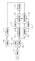
100:制御部、101:探触子、102:送信部、103:受信部、104:断層画像処理部、105:組織追跡部、106:画像合成部、107:表示部、108:弾性率演算部、111:血圧測定部、112:血圧計制御部、120、121:記憶部。100: control unit, 101: probe, 102: transmission unit, 103: reception unit, 104: tomographic image processing unit, 105: tissue tracking unit, 106: image synthesis unit, 107: display unit, 108: elastic modulus calculation Part, 111: blood pressure measurement part, 112: sphygmomanometer control part, 120, 121: storage part.
以下、添付図面を参照して本発明の具体的な形態を説明する。 Hereinafter, specific embodiments of the present invention will be described with reference to the accompanying drawings.
図1および図2は、超音波診断装置の機能構成を示すブロック図である。図示するように、超音波診断装置は、制御手段として制御部100を有する。図示していないが、キーボードやトラックボール、スイッチ、ボタンといったユーザーインターフェース(入力手段)は、制御部100に接続されている。被検体(図示しないが、通常は人である。)に当接して使用される探触子101は送信部102と受信部103に接続されている。送信部102は、制御部100から超音波発信指令(第1の作動信号)S1を受信すると、指定されたタイミングで探触子101を駆動する信号を発生して探触子101に送信する。探触子101は、送信部102から出力された信号に基づいて超音波を発信し、被検体に照射する。また、探触子101は、被検体内部から反射してきた超音波エコーを電気信号に変換する。 1 and 2 are block diagrams showing the functional configuration of the ultrasonic diagnostic apparatus. As shown in the figure, the ultrasonic diagnostic apparatus includes a
受信部103は、送信部102と共に送受信手段を構成しており、被検体内部から反射してきた受信信号を処理して断層画像処理部104と組織追跡部105に出力する。図示しないが、探触子101内には超音波と電気信号を相互に変換する複数の圧電変換素子が配置されており、これらの圧電変換素子を選択し、また圧電変換素子に電圧与えるタイミングを調整し、送受信する超音波の偏向角およびフォーカスを制御する。受信部103はまた、受信信号を増幅するとともに、定められた位置(フォーカス)または方向(偏向角)からの超音波のみを検出する。 The
断層画像処理部104は、フィルタ、検波器、対数増幅器などからなり、受信部103から送信された信号の主に振幅を解析して、被検体の内部構造を画像化する。画像化された画像データは、画像合成部106に送信される。また、画像データは、記憶部120に送信して記憶し、制御部100からの要求に応じて適宜画像合成部106に出力することもできる。 The tomographic
組織追跡部105は、図示しない複数の構成、例えば、受信信号を記憶するメモリ、受信信号間の位相差から上述の式1を用いて超音波の送受信方向に沿う被検体組織の移動量を求める移動量演算部、移動量を元の位置に加算して移動後の位置を求める位置追跡演算部を備えており、被検体組織の超音波の送受信方向に沿う動きを追跡し、追跡位置情報(被検体組織の動きを示す情報)を取得する。組織追跡部105で取得された追跡位置情報は、弾性率演算部108に出力される。また、組織追跡部105で取得した追跡位置情報は、記憶部121に送信して記憶し、制御部100からの要求に応じて適宜弾性率演算部108に出力することもできる。 The
弾性率演算部108は、組織追跡部105又は記憶部121から送信される追跡位置情報をもとに、上述の式3に基づいて検査組織の歪み量を計算する。計算した歪み量は、一時的に記憶部121に送信して記憶し、必要に応じて記憶部121から取得するようにしてもよい。弾性率演算部108はまた、計算された歪み量と、後述する血圧測定部111から送信される被検体の血圧(血圧値)をもとに、上述の式4に基づいて組織の弾性率を演算する。弾性率は、弾性率の値を示す数値データ、または弾性率の値を色データに変換して二次元座標に展開した二次元分布画像データに変換され、画像合成部106に送信される。これら数値データ、画像データは記憶部121に記憶されており、必要に応じて画像合成部106に出力することができる。 Based on the tracking position information transmitted from the
画像合成部106は、弾性率演算部108または記憶部121から出力された弾性率の数値データ又は画像データと、断層画像処理部104又は記憶部120から出力された画像データを合成し、その合成画像を画像表示部107に出力して表示する。記憶部120は合成画像を記憶することもできる。 The
血圧測定部111は非侵襲型の血圧測定器を有する。血圧測定器は、例えば、被検体の上腕部又は手首部に装着される測定部と、測定部の動作を制御する制御部を備えており、制御部100から出力される血圧測定指令(第2の作動信号)S2に基づいて被検体の血圧(血圧値)を制御部100で指示されたタイミングで取得し、その血圧値を弾性率演算部108に出力する。 The blood
血圧測定部111における血圧測定は、超音波の送受信中に行うことができる。この場合、血圧測定後、予め設定した時間後、または予め設定された心拍数後に、超音波の送受信を停止させる。また、血圧測定部111は、複数回血圧を測定し、それら複数の測定結果(血圧値)を平均化処理した値、またはそれら複数の測定結果から歪み量計測時の血圧を推定した値を、血圧値として弾性率演算部108に出力してもよい。そして、弾性率演算部108に提供された血圧値は、記憶部121に送信して記憶され、超音波送受信停止状態(以下「フリーズ状態」という。)で適宜弾性率演算部108に取り出して弾性率の演算に利用される。 Blood pressure measurement in the blood
図5は、上述の超音波診断装置を用いて、血管壁の弾性率を計測した結果の一例を表示した表示部107の表示画面である。図5において、表示画面には血管壁のモノクロ断層画像200に重畳して、当該部位の弾性率の分布を表す弾性率画像201がカラーで表示される。超音波送受信時(以下「ライブ状態」という。)、従来の超音波診断装置同様に、モノクロ断層画像200は数10フレーム/秒ごとに更新表示され、弾性率画像201は1心拍に1回更新表示される。フリーズ状態で、記憶部121から追跡位置情報、歪み量が読み出され、それをもとに弾性率が再計算される。また、弾性率に時間的に同期した断層画像が記憶部120から読み出され、表示部107に表示される。なお、図5において、符号202は断層画像用反射強度スケール、符号203は弾性率画像用弾性率スケール、符号204は生体信号波形(例えば、心電波形)である。 FIG. 5 is a display screen of the
フリーズ状態では、過去の弾性率および断層画像を記憶部121,120から読み出すことができる。この場合、弾性率と弾性率に同期した断層画像、または弾性率と弾性率を算出するために要した心拍期間の断層画像が、記憶部121、120から読み出されて表示される。 In the frozen state, the past elastic modulus and tomographic image can be read from the
このように構成された超音波診断装置、特に血圧測定部111の制御について、さらに詳しく説明する。超音波診断装置では、歪み量の計測が終わり、フリーズ状態になると同時に外部または内部の血圧計を用いて自動的に血圧を計測する。そして、計測された血圧値を用いて現在表示されている弾性率値、弾性率画像が補正される。記憶部121に記憶された追跡位置情報または歪み量を読み出して過去に計測した弾性率を更新するとき、最新の血圧値が利用される。 The ultrasonic diagnostic apparatus configured as described above, particularly the control of the blood
また、超音波診断装置では、歪み量計測中に定期的に(すなわち、予め決められた時間間隔毎に、または予め決められた心拍数毎に)血圧を計測し、常に最新の血圧値を用いて弾性率を自動的に算出する。なお、定期的に計測している血圧値から血圧の揺らぎを予測して歪み計測時の血圧を推定することにより、または、複数回計測した血圧値を平均した血圧を用いることにより、さらに弾性率算出の精度を上げることができる。 In addition, the ultrasonic diagnostic apparatus measures blood pressure periodically during measurement of the amount of distortion (that is, every predetermined time interval or every predetermined heart rate), and always uses the latest blood pressure value. To calculate the elastic modulus automatically. By estimating the blood pressure at the time of strain measurement by predicting fluctuations in blood pressure from regularly measured blood pressure values, or by using the blood pressure obtained by averaging the blood pressure values measured multiple times, the modulus of elasticity is further increased. Calculation accuracy can be improved.
さらに、超音波診断装置では、超音波による計測断面を検者が確定した後、スイッチなどの操作で血圧を計測し、次いで数心拍にわたって超音波により歪み量を計測して弾性率を算出してもよい。弾性率計測後に、自動的に超音波送受信を停止するようにしてもよい。 Furthermore, in the ultrasonic diagnostic apparatus, after the examiner determines the measurement cross section by the ultrasonic wave, the blood pressure is measured by an operation of a switch or the like, and then the elastic modulus is calculated by measuring the distortion amount by the ultrasonic wave over several heartbeats. Also good. You may make it stop ultrasonic transmission / reception automatically after elastic modulus measurement.
さらにまた、超音波送受信停止後に再度血圧を計測し、歪み量を計測する前と後の血圧値から、線形補間あるいは平均などの演算を用いて推定した血圧値を用いることにより、さらに弾性率算出の精度を上げることができる。 Furthermore, by measuring blood pressure again after stopping ultrasonic transmission / reception, and using the blood pressure value estimated from the blood pressure value before and after measuring the amount of distortion using an operation such as linear interpolation or averaging, the elastic modulus is further calculated. Can improve the accuracy.
以上の説明では、血圧測定部111(つまり血圧計)を超音波診断装置内部に設け、制御部100と血圧測定部111を接続し、制御部100からの指令に基づいて血圧測定部111を直接制御するものとしたが、図2に示すように、血圧測定部111(つまり血圧計)は超音波診断装置外部に設け、内部には血圧計制御部(血圧取得部)112のみを設け、制御部100と血圧計制御部112を接続し、制御部100からの指令に基づいて血圧計制御部112が血圧測定部111から血圧値を取得するとともに、血圧計制御部112で取得した血圧値を弾性率演算部108に出力するようにしてもよい。 In the above description, the blood pressure measurement unit 111 (that is, a sphygmomanometer) is provided inside the ultrasonic diagnostic apparatus, the
また、以上の説明では、組織性状値として弾性率を例に挙げたが、組織性状値は組織の粘性率であってもよい。具体的に説明すると、圧力(応力)、歪み、弾性率、粘性率は以下の式5に示す関係を有する。
ところで、図1〜図4では、超音波診断装置の機能を独立したブロックで示しているが、例えば、制御部100、断層画像処理部104、組織追跡部105、画像合成部106、弾性率算出部108、粘性率演算部108’などはCPUに組み込まれたソフトウェアとして実現してもよい。 By the way, in FIG. 1 to FIG. 4, the functions of the ultrasonic diagnostic apparatus are shown as independent blocks. For example, the
本発明は、被検体組織(例えば、生体組織)の動きを追跡して得られた情報をもとに組織性状を求める超音波診断装置に関する。 The present invention relates to an ultrasonic diagnostic apparatus that obtains tissue properties based on information obtained by tracking the movement of a subject tissue (for example, a biological tissue).
超音波診断装置は、超音波を被検体に発信すると共に被検体の組織で反射された超音波(反射エコー信号)を受信し、この受信した超音波の強度を輝度に変換することで、被検体の断層画像を得るものである。また、超音波診断装置の一形態として、反射エコー信号の位相を解析することにより被検体組織の動きを精密に測定し、その測定結果をもとに被検体組織の歪み、弾性率や粘性率などの組織性状を求める試みが為されている。 The ultrasonic diagnostic apparatus transmits an ultrasonic wave to a subject and receives an ultrasonic wave (reflected echo signal) reflected by the tissue of the subject, and converts the intensity of the received ultrasonic wave into a luminance. A tomographic image of the specimen is obtained. As one form of ultrasonic diagnostic equipment, the motion of the subject tissue is accurately measured by analyzing the phase of the reflected echo signal, and the distortion, elastic modulus and viscosity of the subject tissue are based on the measurement result. Attempts have been made to determine the tissue properties.
例えば、特許文献1には、反射エコー信号を検波して得られた出力信号の振幅と位相を用いて、被検体の瞬間的な位置を決定することによって被検体組織の追跡を高精度に行ない、拍動による大振幅変位運動に重畳している微小振動を捕らえる方法が記載されている。
For example, in
図6を用いて、特許文献1に開示された被検体組織追跡方法を説明する。被検体の同一方向に対して、時刻t=0に送信された超音波パルスの受信エコー信号をy(t)、時刻t=ΔTに送信された超音波パルスのエコー信号をy(t+ΔT)とする。また、ある位置(深度)xにある計測点から反射されたエコーの受信時刻txは、パルス送信時刻をt=0とすると、tx=x/(C/2)〔C:被検体内を伝播する超音波の速度〕で与えられる。次に、受信エコー信号y(tx)とy(tx+ΔT)の位相差をΔθ、受信時刻tx付近における超音波の中心周波数をfとすると、この時間ΔT内の計測点の移動量Δxは次の式(1)で与えられる。
この計算を繰り返すことで、被検体内の特定の計測点の位置を追跡できる。つまり、位置(深度)x’から反射されたエコーの受信時刻をtx’とすると、受信エコー信号y(tx’+ΔT)とy(tx’+2ΔT)の位相差をもとに、式(1)と式(2)から2ΔT後の計測点の位置x”を求めることができる。 By repeating this calculation, the position of a specific measurement point in the subject can be tracked. That is, assuming that the reception time of the echo reflected from the position (depth) x ′ is tx ′, the expression (1) is obtained based on the phase difference between the reception echo signals y (tx ′ + ΔT) and y (tx ′ + 2ΔT). And the position x ″ of the measurement point after 2ΔT can be obtained from the equation (2).
特許文献2には、特許文献1の方法をさらに発展させ、心拍による血管壁の内面および外面の各大振幅変位運動を精密に追跡し、大振幅変位運動に重畳されている微小振動の運動速度を求め、その差から血管壁の歪み量を計測し、歪み量と血圧差から局所弾性率を求める方法および、弾性率の空間分布を画像表示する装置が記載されている。
In
図7を参照して、特許文献2に開示された弾性率算出方法を説明する。同文献によれば、探触子101は被検体に対して超音波を照射し、血管、特に動脈からのエコーを受信する。血管壁に測定点A,B(血管の中心軸を含む横断面上にあって該中心軸から径方向に異なる距離を有する2点)を設定し、測定点A,Bからの受信信号を特許文献1に示された方法で解析し、測定点A,Bの動きを追跡する。ここで、動脈は心拍によって収縮拡張を繰り返しており、心臓収縮期には血管自体は膨張すると共に、急激に血管壁の厚みが減少し、心臓拡張期には血管自体は収縮すると共に、ゆっくりと血管壁の厚みが増加する。そのため、測定点A,Bは、追跡波形TA,TBで示す周期的な挙動を示し、これらの追跡波形TA,TBの差から測定点A−B間の厚み(距離)変化波形Wが求まる。
With reference to FIG. 7, the elastic modulus calculation method disclosed in
したがって、厚み変化波形Wの変化量をΔW、測定点初期化時の基準厚みをWsとすると、測定点A−B間の歪み量εは式(3)で与えられる。
この歪み量εが血管壁にかかる血圧差ΔPによりもたらされたものとすると、測定点A−B間の弾性率Erは式(4)で与えられる。
しかしながら、特許文献2に示された方法では、血圧値はあらかじめ測定しておいたものを検者が超音波診断装置にテンキー等の入力部を通じて手入力している。しかし、測定から歪み量の計測までには相当な時間差が生じる。例えば、血圧値の入力は1回であるが、歪み量は数箇所を計測するため、血圧計測と最後の歪み量の計測の間には数分から数十分の時間差があるし、血圧値は安静時でも刻々と変化する。そのため、弾性率計測の精度が低下するという問題があった。また、歪み量計測の度に血圧を計測して入力することは、検者にとって大きな負担であった。なお、特許文献2には、連続血圧計を使用して血圧値を連続的に取得する方法が示されているが、連続血圧計は動脈内に直接挿入するため、被検者に過度の負担を強いることになり、非侵襲で且つ簡便であるという超音波診断の利点を大きく削ぐものであった。
However, in the method disclosed in
本発明では、一般的な非侵襲性の血圧計を使用しつつ、精度よく弾性率を計測する装置を提供することを目的とする。 An object of the present invention is to provide an apparatus for measuring an elastic modulus with high accuracy while using a general non-invasive blood pressure monitor.
この目的を達成するために、本発明に係る超音波診断装置は、
(a) 被検体に超音波を送信すると共に被検体の内部で反射された超音波を受信する送受信手段と、
(b) 受信した超音波をもとに上記送受信手段が作成した受信信号から被検体内の組織の動きを追跡する組織追跡手段と、
(c) 被検体の血圧を測定する非侵襲型血圧測定手段と、
(d) 上記送受信手段に第1の作動信号を出力して上記送受信手段を駆動し、上記血圧測定手段に第2の作動信号を出力して上記血圧測定手段を駆動する制御手段と、
(e) 上記組織追跡手段が追跡した組織の動きと上記血圧測定手段が測定した血圧から上記被検体の組織性状値を演算する組織性状値演算手段を備えており、
(f) 上記血圧測定手段は、上記制御手段から出力された第2の作動信号に基づいて被献体の血圧を測定し、測定された血圧を上記組織性状演算手段に送信するようにしてあることを特徴とするものである。
In order to achieve this object, an ultrasonic diagnostic apparatus according to the present invention includes:
(A) transmitting / receiving means for transmitting ultrasonic waves to the subject and receiving ultrasonic waves reflected inside the subject;
(B) a tissue tracking means for tracking the movement of the tissue in the subject from the received signal created by the transmission / reception means based on the received ultrasound;
(C) a non-invasive blood pressure measuring means for measuring the blood pressure of the subject;
(D) a control unit that outputs a first operation signal to the transmission / reception unit to drive the transmission / reception unit, and outputs a second operation signal to the blood pressure measurement unit to drive the blood pressure measurement unit;
(E) comprising tissue property value calculating means for calculating the tissue property value of the subject from the movement of the tissue tracked by the tissue tracking means and the blood pressure measured by the blood pressure measuring means;
(F) The blood pressure measurement means measures the blood pressure of the contributor based on the second operation signal output from the control means, and transmits the measured blood pressure to the tissue property calculation means. It is characterized by.
本発明の他の形態の超音波診断装置は、
(a) 被検体に超音波を送信すると共に被検体の内部で反射された超音波を受信する送受信手段と、
(b) 受信した超音波をもとに上記送受信手段が作成した受信信号から被検体内の組織の動きを追跡する組織追跡手段と、
(c) 被検体の血圧を測定する非侵襲型血圧測定手段と、
(d) 上記被検体の血圧を上記血圧測定手段から取得する血圧取得手段と、
(e) 上記送受信手段に第1の作動信号を出力して上記送受信手段を駆動し、上記血圧取得手段に第2の作動信号を出力して上記血圧測定手段で測定された血圧を取得させる制御手段と、
(f) 上記組織追跡手段が追跡した組織の動きと上記血圧取得手段が取得した血圧から上記被検体の組織性状値を演算する組織性状値演算手段を備えており、
(g) 上記血圧取得手段は、上記制御手段から出力された第2の作動信号に基づいて上記血圧測定手段から被献体の血圧を取得し、取得された血圧を上記組織性状演算手段に送信するようにしてあることを特徴とするものである。
An ultrasonic diagnostic apparatus according to another aspect of the present invention
(A) transmitting / receiving means for transmitting ultrasonic waves to the subject and receiving ultrasonic waves reflected inside the subject;
(B) a tissue tracking means for tracking the movement of the tissue in the subject from the received signal created by the transmission / reception means based on the received ultrasound;
(C) a non-invasive blood pressure measuring means for measuring the blood pressure of the subject;
(D) blood pressure acquisition means for acquiring the blood pressure of the subject from the blood pressure measurement means;
(E) Control that outputs the first operation signal to the transmission / reception means to drive the transmission / reception means, and outputs the second operation signal to the blood pressure acquisition means to acquire the blood pressure measured by the blood pressure measurement means. Means,
(F) comprising tissue property value calculating means for calculating the tissue property value of the subject from the movement of the tissue tracked by the tissue tracking means and the blood pressure acquired by the blood pressure acquiring means;
(G) The blood pressure acquisition unit acquires the blood pressure of the donated body from the blood pressure measurement unit based on the second operation signal output from the control unit, and transmits the acquired blood pressure to the tissue property calculation unit. In this way, it is characterized by that.
これらの形態の超音波診断装置では、上記血圧測定手段が、上記送受信手段が被検体で反射された超音波を受信している間又は受信した後、被検体の血圧を測定することが好ましい。 In the ultrasonic diagnostic apparatus of these forms, it is preferable that the blood pressure measurement unit measures the blood pressure of the subject while or after the transmission / reception unit receives the ultrasound reflected by the subject.
また、上記血圧測定手段は血圧の測定を複数回行って複数の血圧を取得し、取得した複数の血圧の平均値、または取得した複数の血圧から歪み量取得時の血圧値を推定した値を上記組織性状値演算手段に血圧として送信してもよい。 In addition, the blood pressure measurement unit obtains a plurality of blood pressures by measuring the blood pressure a plurality of times, and obtains an average value of the acquired plurality of blood pressures or a value obtained by estimating the blood pressure value at the time of acquiring the strain amount from the plurality of acquired blood pressures. The blood pressure may be transmitted as blood pressure to the tissue property value calculation means.
さらに、上記組織性状値が組織の弾性率であることを特徴とするものである。 Further, the tissue property value is an elastic modulus of the tissue.
このような構成を備えた超音波診断装置によれば、制御手段からの指令に基づいて非侵襲型血圧測定手段が血圧を測定し、測定された血圧値が組織性状演算手段に自動的に入力される。そのため、必要に応じて被検体の血圧を遅滞なく取得して組織性状値を演算できるので、被検体の組織性状値を精度よく取得し、診断に有用な情報を提供できる。 According to the ultrasonic diagnostic apparatus having such a configuration, the noninvasive blood pressure measurement unit measures the blood pressure based on a command from the control unit, and the measured blood pressure value is automatically input to the tissue property calculation unit. Is done. Therefore, if necessary, the blood pressure of the subject can be acquired without delay and the tissue property value can be calculated. Therefore, the tissue property value of the subject can be obtained with high accuracy and useful information for diagnosis can be provided.
以下、添付図面を参照して本発明の具体的な形態を説明する。 Hereinafter, specific embodiments of the present invention will be described with reference to the accompanying drawings.
図1および図2は、超音波診断装置の機能構成を示すブロック図である。図示するように、超音波診断装置は、制御手段として制御部100を有する。図示していないが、キーボードやトラックボール、スイッチ、ボタンといったユーザーインターフェース(入力手段)は、制御部100に接続されている。被検体(図示しないが、通常は人である。)に当接して使用される探触子101は送信部102と受信部103に接続されている。送信部102は、制御部100から超音波発信指令(第1の作動信号)S1を受信すると、指定されたタイミングで探触子101を駆動する信号を発生して探触子101に送信する。探触子101は、送信部102から出力された信号に基づいて超音波を発信し、被検体に照射する。また、探触子101は、被検体内部から反射してきた超音波エコーを電気信号に変換する。
1 and 2 are block diagrams showing the functional configuration of the ultrasonic diagnostic apparatus. As shown in the figure, the ultrasonic diagnostic apparatus includes a
受信部103は、送信部102と共に送受信手段を構成しており、被検体内部から反射してきた受信信号を処理して断層画像処理部104と組織追跡部105に出力する。図示しないが、探触子101内には超音波と電気信号を相互に変換する複数の圧電変換素子が配置されており、これらの圧電変換素子を選択し、また圧電変換素子に電圧与えるタイミングを調整し、送受信する超音波の偏向角およびフォーカスを制御する。受信部103はまた、受信信号を増幅するとともに、定められた位置(フォーカス)または方向(偏向角)からの超音波のみを検出する。
The
断層画像処理部104は、フィルタ、検波器、対数増幅器などからなり、受信部103から送信された信号の主に振幅を解析して、被検体の内部構造を画像化する。画像化された画像データは、画像合成部106に送信される。また、画像データは、記憶部120に送信して記憶し、制御部100からの要求に応じて適宜画像合成部106に出力することもできる。
The tomographic
組織追跡部105は、図示しない複数の構成、例えば、受信信号を記憶するメモリ、受信信号間の位相差から上述の式1を用いて超音波の送受信方向に沿う被検体組織の移動量を求める移動量演算部、移動量を元の位置に加算して移動後の位置を求める位置追跡演算部を備えており、被検体組織の超音波の送受信方向に沿う動きを追跡し、追跡位置情報(被検体組織の動きを示す情報)を取得する。組織追跡部105で取得された追跡位置情報は、弾性率演算部108に出力される。また、組織追跡部105で取得した追跡位置情報は、記憶部121に送信して記憶し、制御部100からの要求に応じて適宜弾性率演算部108に出力することもできる。
The
弾性率演算部108は、組織追跡部105又は記憶部121から送信される追跡位置情報をもとに、上述の式3に基づいて検査組織の歪み量を計算する。計算した歪み量は、一時的に記憶部121に送信して記憶し、必要に応じて記憶部121から取得するようにしてもよい。弾性率演算部108はまた、計算された歪み量と、後述する血圧測定部111から送信される被検体の血圧(血圧値)をもとに、上述の式4に基づいて組織の弾性率を演算する。弾性率は、弾性率の値を示す数値データ、または弾性率の値を色データに変換して二次元座標に展開した二次元分布画像データに変換され、画像合成部106に送信される。これら数値データ、画像データは記憶部121に記憶されており、必要に応じて画像合成部106に出力することができる。
Based on the tracking position information transmitted from the
画像合成部106は、弾性率演算部108は記憶部121から出力された弾性率の数値データ又は画像データと、断層画像処理部104又は記憶部120から出力された弾性画像を合成し、その合成画像を画像表示部107に出力して表示する。記憶部120は合成画像を記憶することもできる。
The
血圧測定部111は非侵襲型の血圧測定器を有する。血圧測定器は、例えば、被検体の上腕部又は手首部に装着される測定部と、測定部の動作を制御する制御部を備えており、制御部100から出力される血圧測定指令(第2の作動信号)S2に基づいて被検体の血圧(血圧値)を制御部100で指示されたタイミングで取得し、その血圧値を弾性率演算部108に出力する。
The blood
血圧測定部111における血圧測定は、超音波の送受信中に行うことができる。この場合、血圧測定後、予め設定した時間後、または予め設定された心拍数後に、超音波の送受信を停止させる。また、血圧測定部111は、複数回血圧を測定し、それら複数の測定結果(血圧値)を平均化処理した値、またはそれら複数の測定結果から歪み量計測時の血圧を推定した値を、血圧値として弾性率演算部108に出力してもよい。そして、弾性率演算部108に提供された血圧値は、記憶部121に送信して記憶され、超音波送受信停止状態(以下「フリーズ状態」という。)で適宜弾性率演算部108に取り出して弾性率の演算に利用される。
Blood pressure measurement in the blood
図5は、上述の超音波診断装置を用いて、血管壁の弾性率を計測した結果の一例を表示した表示部107の表示画面である。図5において、表示画面には血管壁のモノクロ断層画像200に重畳して、当該部位の弾性率の分布を表す弾性率画像201がカラーで表示される。超音波送受信時(以下「ライブ状態」という。)、従来の超音波診断装置同様に、モノクロ断層画像200は数10フレーム/秒ごとに更新表示され、弾性率画像201は1心拍に1回更新表示される。フリーズ状態で、記憶部121から追跡位置情報、歪み量が読み出され、それをもとに弾性率が再計算される。また、弾性率に時間的に同期した断層画像が記憶部120から読み出され、表示部107に表示される。なお、図5において、符号202は断層画像用反射強度スケール、符号203は弾性率画像用弾性率スケール、符号204は生体信号波形(例えば、心電波形)である。
FIG. 5 is a display screen of the
フリーズ状態では、過去の弾性率および断層画像を記憶部121,120から読み出すことができる。この場合、弾性率と弾性率に同期した断層画像、または弾性率と弾性率を算出するために要した心拍期間の断層画像が、記憶部121、120から読み出されて表示される。
In the frozen state, the past elastic modulus and tomographic image can be read from the
このように構成された超音波診断装置、特に血圧測定部111の制御について、さらに詳しく説明する。超音波診断装置では、歪み量の計測が終わり、フリーズ状態になると同時に外部または内部の血圧計を用いて自動的に血圧を計測する。そして、計測された血圧値を用いて現在表示されている弾性率値、弾性率画像が補正される。記憶部121に記憶された追跡位置情報または歪み量を読み出して過去に計測した弾性率を更新するとき、最新の血圧値が利用される。
The ultrasonic diagnostic apparatus configured as described above, particularly the control of the blood
また、超音波診断装置では、歪み量計測中に定期的に(すなわち、予め決められた時間間隔毎に、または予め決められた心拍数毎に)血圧を計測し、常に最新の血圧値を用いて弾性率を自動的に算出する。なお、定期的に計測している血圧値から血圧の揺らぎを予測して歪み計測時の血圧を推定することにより、または、複数回計測した血圧値を平均した血圧を用いることにより、さらに弾性率算出の精度を上げることができる。 In addition, the ultrasonic diagnostic apparatus measures blood pressure periodically during measurement of the amount of distortion (that is, every predetermined time interval or every predetermined heart rate), and always uses the latest blood pressure value. To calculate the elastic modulus automatically. The elasticity modulus can be further increased by predicting blood pressure fluctuations from regularly measured blood pressure values and estimating blood pressure at the time of strain measurement, or by using blood pressure obtained by averaging blood pressure values measured multiple times. Calculation accuracy can be improved.
さらに、超音波診断装置では、超音波による計測断面を検者が確定した後、スイッチなどの操作で血圧を計測し、次いで数心拍にわたって超音波により歪み量を計測して弾性率を算出してもよい。弾性率計測後に、自動的に超音波送受信を停止するようにしてもよい。 Furthermore, in the ultrasonic diagnostic apparatus, after the examiner determines the measurement cross section by the ultrasonic wave, the blood pressure is measured by an operation of a switch or the like, and then the elastic modulus is calculated by measuring the distortion amount by the ultrasonic wave over several heartbeats. Also good. You may make it stop ultrasonic transmission / reception automatically after elastic modulus measurement.
さらにまた、超音波送受信停止後に再度血圧を計測し、歪み量を計測する前と後の血圧値から、線形補間あるいは平均などの演算を用いて推定した血圧値を用いることにより、さらに弾性率算出の精度を上げることができる。 Furthermore, by measuring blood pressure again after stopping ultrasonic transmission / reception, and using the blood pressure value estimated from the blood pressure value before and after measuring the amount of distortion using an operation such as linear interpolation or averaging, the elastic modulus is further calculated. Can improve the accuracy.
以上の説明では、血圧測定部111(つまり血圧計)を超音波診断装置内部に設け、制御部100と血圧測定部111を接続し、制御部100からの指令に基づいて血圧測定部111を直接制御するものとしたが、図2に示すように、血圧測定部111(つまり血圧計)は超音波診断装置外部に設け、内部には血圧計制御部112のみを設け、制御部100と血圧計制御部112を接続し、制御部100からの指令に基づいて血圧計制御部112が血圧測定部111から血圧値を取得するとともに、血圧計制御部112で取得した血圧値を弾性率演算部108に出力するようにしてもよい。
In the above description, the blood pressure measurement unit 111 (that is, a sphygmomanometer) is provided inside the ultrasonic diagnostic apparatus, the
また、以上の説明では、組織性状値として弾性率を例に挙げたが、組織性状値は組織の粘性率であってもよい。具体的に説明すると、圧力(応力)、歪み、弾性率、粘性率は以下の式5に示す関係を有する。
ところで、図1〜図4では、超音波診断装置の機能を独立したブロックで示しているが、例えば、制御部100、断層画像処理部104、組織追跡部105、画像合成部106、弾性率算出部108、粘性率演算部108’などはCPUに組み込まれたソフトウェアとして実現してもよい。
By the way, in FIG. 1 to FIG. 4, the functions of the ultrasonic diagnostic apparatus are shown as independent blocks. For example, the
100:制御部、101:探触子、102:送信部、103:受信部、104:断層画像処理部、105:組織追跡部、106:画像合成部、107:表示部、108:弾性率演算部、111:血圧測定部、112:血圧計制御部、120、121:記憶部。 100: control unit, 101: probe, 102: transmission unit, 103: reception unit, 104: tomographic image processing unit, 105: tissue tracking unit, 106: image synthesis unit, 107: display unit, 108: elastic modulus calculation Part, 111: blood pressure measurement part, 112: sphygmomanometer control part, 120, 121: storage part.
Claims (6)
(b)受信した超音波をもとに上記送受信手段が作成した受信信号から被検体内の組織の動きを追跡する組織追跡手段と、
(c)被検体の血圧を測定する非侵襲型血圧測定手段と、
(d)上記送受信手段に第1の作動信号を出力して上記送受信手段を駆動し、上記血圧測定手段に第2の作動信号を出力して上記血圧測定手段を駆動する制御手段と、
(e)上記組織追跡手段が追跡した組織の動きと上記血圧測定手段が測定した血圧から上記被検体の組織性状値を演算する組織性状値演算手段を備えており、
(f)上記血圧測定手段は、上記制御手段から出力された第2の作動信号に基づいて被献体の血圧を測定し、測定された血圧を上記組織性状演算手段に送信するようにしてあることを特徴とする超音波診断装置。(A) transmitting / receiving means for transmitting ultrasonic waves to the subject and receiving ultrasonic waves reflected inside the subject;
(B) a tissue tracking means for tracking the movement of the tissue in the subject from the received signal created by the transmission / reception means based on the received ultrasound;
(C) noninvasive blood pressure measuring means for measuring the blood pressure of the subject;
(D) a control unit that outputs a first operation signal to the transmission / reception unit to drive the transmission / reception unit, and outputs a second operation signal to the blood pressure measurement unit to drive the blood pressure measurement unit;
(E) comprising tissue property value calculating means for calculating the tissue property value of the subject from the movement of the tissue tracked by the tissue tracking means and the blood pressure measured by the blood pressure measuring means;
(F) The blood pressure measuring means measures the blood pressure of the contributor based on the second operation signal output from the control means, and transmits the measured blood pressure to the tissue property calculating means. An ultrasonic diagnostic apparatus characterized by the above.
上記制御手段は、上記第2の作動信号に基づいて、上記血圧測定部を作動して上記被検体の血圧を上記血圧計制御部に取得させるとともに上記組織性状演算手段に送信させることを特徴とする請求項1に記載の超音波診断装置。The blood pressure measurement means includes a blood pressure measurement unit that measures the blood pressure of the subject, and a sphygmomanometer control unit that operates the blood pressure measurement unit to acquire the blood pressure of the subject from the blood pressure measurement unit,
The control unit operates the blood pressure measurement unit based on the second operation signal to cause the blood pressure monitor control unit to acquire the blood pressure of the subject and transmit the blood pressure to the tissue property calculation unit. The ultrasonic diagnostic apparatus according to claim 1.
Applications Claiming Priority (3)
| Application Number | Priority Date | Filing Date | Title |
|---|---|---|---|
| JP2005150476 | 2005-05-24 | ||
| JP2005150476 | 2005-05-24 | ||
| PCT/JP2006/310147 WO2006126485A1 (en) | 2005-05-24 | 2006-05-22 | Ultrasonograph |
Publications (1)
| Publication Number | Publication Date |
|---|---|
| JPWO2006126485A1 true JPWO2006126485A1 (en) | 2008-12-25 |
Family
ID=37451911
Family Applications (1)
| Application Number | Title | Priority Date | Filing Date |
|---|---|---|---|
| JP2007517812A Withdrawn JPWO2006126485A1 (en) | 2005-05-24 | 2006-05-22 | Ultrasonic diagnostic equipment |
Country Status (2)
| Country | Link |
|---|---|
| JP (1) | JPWO2006126485A1 (en) |
| WO (1) | WO2006126485A1 (en) |
Families Citing this family (2)
| Publication number | Priority date | Publication date | Assignee | Title |
|---|---|---|---|---|
| US7912264B2 (en) * | 2007-08-03 | 2011-03-22 | Siemens Medical Solutions Usa, Inc. | Multi-volume rendering of single mode data in medical diagnostic imaging |
| JP5863628B2 (en) * | 2012-11-30 | 2016-02-16 | ジーイー・メディカル・システムズ・グローバル・テクノロジー・カンパニー・エルエルシー | Ultrasonic diagnostic apparatus and control program therefor |
Family Cites Families (4)
| Publication number | Priority date | Publication date | Assignee | Title |
|---|---|---|---|---|
| JP3857788B2 (en) * | 1997-09-01 | 2006-12-13 | テルモ株式会社 | Cardiovascular information measurement system |
| JP3398080B2 (en) * | 1999-02-10 | 2003-04-21 | 科学技術振興事業団 | Vascular lesion diagnostic system and diagnostic program storage medium |
| JP4587570B2 (en) * | 2001-01-10 | 2010-11-24 | ジーイー・メディカル・システムズ・グローバル・テクノロジー・カンパニー・エルエルシー | Vascular elastic modulus measuring method, vascular elastic modulus calculating apparatus, and ultrasonic diagnostic apparatus |
| JP2005027941A (en) * | 2003-07-08 | 2005-02-03 | Matsushita Electric Ind Co Ltd | Ultrasonic diagnostic equipment |
-
2006
- 2006-05-22 JP JP2007517812A patent/JPWO2006126485A1/en not_active Withdrawn
- 2006-05-22 WO PCT/JP2006/310147 patent/WO2006126485A1/en not_active Ceased
Also Published As
| Publication number | Publication date |
|---|---|
| WO2006126485A1 (en) | 2006-11-30 |
Similar Documents
| Publication | Publication Date | Title |
|---|---|---|
| US9826959B2 (en) | Ultrasonic diagnostic device | |
| JP4890554B2 (en) | Ultrasonic diagnostic equipment | |
| JP4189405B2 (en) | Ultrasonic diagnostic equipment | |
| US6770034B2 (en) | Ultrasonic diagnostic apparatus | |
| JP5158880B2 (en) | Ultrasonic diagnostic equipment | |
| JP5161954B2 (en) | Ultrasonic diagnostic equipment | |
| WO2006082966A1 (en) | Ultrasonographic device | |
| CN102670254A (en) | Ultrasound diagnostic apparatus and method of determining elasticity index reliability | |
| WO2004110280A1 (en) | Ultrasonic diagnosis device | |
| JP4667394B2 (en) | Ultrasonic diagnostic equipment | |
| JP5384919B2 (en) | Ultrasonic diagnostic equipment | |
| WO2008038615A1 (en) | Ultrasonographic device | |
| US9579084B2 (en) | Ultrasound diagnostic apparatus | |
| JP4091365B2 (en) | Ultrasonic diagnostic equipment | |
| JP2010269018A (en) | Ultrasonic diagnostic equipment | |
| JP4766546B2 (en) | Ultrasonic diagnostic equipment | |
| WO2006129545A1 (en) | Ultrasonograph | |
| JP2010110373A (en) | Ultrasonic diagnostic apparatus with function of displaying arteriosclerosis risk | |
| JPWO2007080870A1 (en) | Ultrasonic diagnostic equipment | |
| JP2009039277A (en) | Ultrasonic diagnostic equipment | |
| JPWO2007034738A1 (en) | Ultrasonic diagnostic equipment | |
| JP2006325704A (en) | Ultrasonic diagnostic equipment | |
| JP5462474B2 (en) | Ultrasonic diagnostic equipment | |
| JPWO2006126485A1 (en) | Ultrasonic diagnostic equipment | |
| JP2008212548A (en) | Ultrasonic diagnostic equipment |
Legal Events
| Date | Code | Title | Description |
|---|---|---|---|
| A621 | Written request for application examination |
Free format text: JAPANESE INTERMEDIATE CODE: A621 Effective date: 20090427 |
|
| A761 | Written withdrawal of application |
Free format text: JAPANESE INTERMEDIATE CODE: A761 Effective date: 20110121 |