JPWO2004107837A1 - Cooling system - Google Patents
Cooling system Download PDFInfo
- Publication number
- JPWO2004107837A1 JPWO2004107837A1 JP2005506582A JP2005506582A JPWO2004107837A1 JP WO2004107837 A1 JPWO2004107837 A1 JP WO2004107837A1 JP 2005506582 A JP2005506582 A JP 2005506582A JP 2005506582 A JP2005506582 A JP 2005506582A JP WO2004107837 A1 JPWO2004107837 A1 JP WO2004107837A1
- Authority
- JP
- Japan
- Prior art keywords
- heat receiving
- cooling
- cooling device
- heat
- present
- Prior art date
- Legal status (The legal status is an assumption and is not a legal conclusion. Google has not performed a legal analysis and makes no representation as to the accuracy of the status listed.)
- Granted
Links
Images


Classifications
-
- G—PHYSICS
- G06—COMPUTING OR CALCULATING; COUNTING
- G06F—ELECTRIC DIGITAL DATA PROCESSING
- G06F1/00—Details not covered by groups G06F3/00 - G06F13/00 and G06F21/00
- G06F1/16—Constructional details or arrangements
- G06F1/20—Cooling means
-
- H—ELECTRICITY
- H10—SEMICONDUCTOR DEVICES; ELECTRIC SOLID-STATE DEVICES NOT OTHERWISE PROVIDED FOR
- H10W—GENERIC PACKAGES, INTERCONNECTIONS, CONNECTORS OR OTHER CONSTRUCTIONAL DETAILS OF DEVICES COVERED BY CLASS H10
- H10W40/00—Arrangements for thermal protection or thermal control
- H10W40/40—Arrangements for thermal protection or thermal control involving heat exchange by flowing fluids
- H10W40/47—Arrangements for thermal protection or thermal control involving heat exchange by flowing fluids by flowing liquids, e.g. forced water cooling
-
- G—PHYSICS
- G06—COMPUTING OR CALCULATING; COUNTING
- G06F—ELECTRIC DIGITAL DATA PROCESSING
- G06F2200/00—Indexing scheme relating to G06F1/04 - G06F1/32
- G06F2200/20—Indexing scheme relating to G06F1/20
- G06F2200/201—Cooling arrangements using cooling fluid
Landscapes
- Engineering & Computer Science (AREA)
- Theoretical Computer Science (AREA)
- Human Computer Interaction (AREA)
- Physics & Mathematics (AREA)
- General Engineering & Computer Science (AREA)
- General Physics & Mathematics (AREA)
- Projection Apparatus (AREA)
- Cooling Or The Like Of Electrical Apparatus (AREA)
- Cooling Or The Like Of Semiconductors Or Solid State Devices (AREA)
Abstract
たとえば、投写型表示装置の映像素子、パーソナルコンピュータのCPU、半導体レーザー装置の半導体レーザー等を効率よく冷却することが困難であった。発熱体と直接的にまたは間接的に熱的接合される受熱ケーシング108と、受熱ケーシング108の内部と連通されたホース116およびホース117を含む手段と、受熱ケーシング108の内部、およびホース116およびホース117を含む手段に充填された液状媒体110と、充填された液状媒体110を循環させる、受熱ケーシング108の内部に設けられた送液ポンプ107と、循環させられる液状媒体110を冷却する放熱器114および放熱ファン115を含む手段とを備えた冷却装置である。For example, it has been difficult to efficiently cool an image element of a projection display device, a CPU of a personal computer, a semiconductor laser of a semiconductor laser device, and the like. A heat receiving casing 108 that is directly or indirectly thermally bonded to the heating element, means including a hose 116 and a hose 117 communicated with the inside of the heat receiving casing 108, an inside of the heat receiving casing 108, and the hose 116 and the hose 117, a liquid medium 110 filled in a means including 117, a liquid feed pump 107 provided inside the heat receiving casing 108 for circulating the filled liquid medium 110, and a radiator 114 for cooling the liquid medium 110 to be circulated. And a cooling device provided with a means including a heat radiating fan 115.
Description
本発明は、たとえば、画像を投写レンズによりスクリーン上に拡大投写する投写型表示装置、パーソナルコンピュータ、半導体レーザー装置等の電子機器に利用可能な、筐体内部に配設された半導体やCPUなどの発熱電子部品を液状媒体を循環させて冷却または温度制御する冷却装置に関するものである。 The present invention is applicable to, for example, a semiconductor or a CPU disposed in a housing, which can be used in an electronic apparatus such as a projection display device that enlarges and projects an image on a screen using a projection lens, a personal computer, and a semiconductor laser device. The present invention relates to a cooling device that cools or controls the temperature of a heat generating electronic component by circulating a liquid medium.
ノートタイプのパーソナルコンピュータや移動体通信機器に代表される携帯型の電子機器は、マルチメディア情報を処理するためのマイクロプロセッサを装備している。
この種のマイクロプロセッサは、演算速度の高速化や多機能化に伴い、動作中の発熱量が急速に増大する傾向がある。
そのため、マイクロプロセッサの動作を安定的に保証するためには、その発熱量に見合う冷却性を高める必要がある。
また、半導体レーザー光源装置に代表される電子機器は、高出力化やビームの波長安定性確保の観点から、発振源となる半導体を適当な温度に温度制御する必要がある。
また、近年の小型化の要望のため、その温度制御装置の小型化と高い温度制御性能が、要求されるようになってきている。
また、ライトバルブ上で映像信号に変調された画像を照明光で照射し、投写レンズによりスクリーン上にその画像を拡大投写する投写型表示装置に代表される表示装置においては、画像情報をより鮮明に投影するために高解像度のライトバルブからなる映像素子が用いられ、さらに投影画面の明るい高輝度化が促進されている。
また、高輝度が求められる投写型表示装置の映像素子は、原理的には入射される光量に対し、有効にスクリーンに投影されない成分等の光による熱量を吸収するため、映像素子の発熱が、輝度アップの制限となっている。
その対策として、映像素子は透過型液晶表示素子に代わって、液晶等による反射型映像素子が使用されるようになってきている。
反射型映像素子であっても僅かの光吸収が発生するために、この反射型映像素子を強制的に冷却する必要がある。
このため反射型映像素子を精度よく位置決めする調整機構と、この反射型映像素子を強制冷却するための冷却素子と、その冷却素子の放熱側を冷却するヒートシンクおよびそのヒートシンクを空冷する冷却ファンとが一体となった冷却装置が、利用されるようになってきている。
以下、電子機器や表示装置の熱対策に関する従来の技術について、より具体的に説明する。
ここでは、一般的な反射型映像素子を用いた投写型表示装置の冷却装置を例として説明する。
投写型表示装置の光学系は、基本的に、光源ランプユニットと、その光源ランプユニットの光源からの白色光を赤(R)、緑(G)、青(B)に色分解し、これらの光を画像情報に応じて変調する反射型液晶パネル等から構成された映像素子と、その変調された光を色合成する光学ユニットと、その色合成された光をスクリーン上に拡大投影する投写レンズユニットとで構成されている。
最近では、投写型表示装置においては、画像情報をより鮮明に投影するために高解像度の映像素子が用いられてきており、さらに投影画面の明るい高輝度化が促進されていることは、上述したとおりである。
従来のR、G、Bの各反射型映像素子を用いた3板式投写型表示装置とその冷却装置について、図10と図11を用いてその一例を説明する。
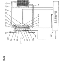
まず、図10は、従来の投写型表示装置の概略構成を示す図である。
従来の投写型表示装置は、画像情報を光学的に拡大投影するための光源である光源ランプユニット1と、その光源ランプユニット1の光から赤外線や紫外線を除去し、可視光のみを透過するためのフィルター2と、そのフィルター2からの可視光を集光するための照射光学ユニット3と、前記照射光学ユニット3で集光された光が反射プリズムユニット6を通過した後、これを色分解して反射型映像素子4a、4b、4cに導くとともに、この反射型映像素子4a、4b、4cで光学的に画像情報に生成された光を色合成する色分離合成プリズムユニット5と、前記色分離合成プリズムユニット5で合成された画像情報が前記反射プリズムユニット6で反射されてこれを拡大投射するための投写レンズユニット7とで構成されている。
光源ランプユニット1は、一般的に発光効率が高いとされる超高圧水銀ランプ1aと、光を効率よく集光するための凹面鏡1bで構成されている。
光源ランプユニット1からの光をR、G、Bに色分解および色合成する色分離合成プリズムユニット5は、例えば白色光を波長的に選択する青反射ダイクロイックミラーと、赤反射ダイクロイックミラーと、緑透過のダイクロイックミラーで構成される。
そして、各々の膜特性から白色光は、R、G、Bに色分解されて、各R、G、Bの反射型映像素子4a、4b、4cへ導かれるとともに、その反射型映像素子4a、4b、4cで画像情報に変調された光は、再び色分離合成プリズムユニット5で合成される。
反射プリズムユニット6は、照射光学ユニット3からの光を透過するとともに色分離合成プリズムユニット5で色合成された光を投写レンズユニット7に導く、いわゆる、ハーフミラー構成の一体型プリズムである。
図11は、従来の反射型映像素子の冷却装置を示す概略断面図である。
なお、この図11では、反射型映像素子4c部分のみを示しているが、反射型映像素子4aと4b部分についても同様の構成となっている。
反射型映像素子4cは、一方の面が、平面的位置調整やフォーカス調整が可能な位置調整機構8に接着剤等で接合固定されており、位置調整機構8は、色分離合成プリズムユニット5に対接あるいは接着剤等で正確に位置決め固定されている。
また、反射型映像素子4cの他方の面は、半導体で構成された電子冷却素子9に熱伝導としての役目も果たすホルダー10を介して接合されている。
電子冷却素子9には、その放熱のためのヒートシンク11が接合され、ヒートシンク11には、これを冷却するための冷却ファン12が接合されている。
そして、この冷却ファン12とヒートシンク11とホルダー10は、ネジ等(図示なし)で一体的に組み立てられている。
しかしながら、上記のような従来の冷却装置では、より高輝度を目指した投写型表示装置の場合、反射型映像素子4a、4b、4cにより多くの光が集中するため、冷却性能を向上させる必要がある。
そのため、より大きな能力を有する電子冷却素子9、ヒートシンク11、冷却ファン12が必要となり、これは装置の大型化のみならず、重量増加を招くことになる。
また、この冷却装置は、電子冷却素子9の吸熱量に見合った消費電力による発熱量と反射型映像素子の発熱量との合計発熱量を放熱する必要があるため、冷却ファン12が想像以上に大型化する。
また、冷却ファン12は、ヒートシンク11に接合しているために、通風抵抗が過大となって送風騒音が大きくなることもある。
さらに、電子冷却素子9の吸熱量を大きくした場合、熱伝導部材として機能するホルダー10は、電子冷却素子9の接合部側が雰囲気温度よりも大きく低温側となり、このため結露が発生することもある。
また、冷却ファン12の構造上、その中央部は、冷却ファン12のモータ駆動部のためにヒートシンク11の外周部のみ図面の矢印のように通風冷却され、ヒートシンク11の冷却効率を悪化させやすい。
一方、放熱経路で見ると、反射型映像素子4cとホルダー10との間、ホルダー10と電子冷却素子9との間、および電子冷却素子9とヒートシンク11との間で、3カ所の部材接合部が存在する。
このため、熱移動のインピーダンス、すなわち熱抵抗が非常に大きくなり、放熱能力を非常に大きく設計しなければならないことが普通であった。
さらに、近年の投写型表示装置の高輝度化に伴い、光源ランプユニットの駆動電力も大きくなってきている。
電子冷却素子9の吸熱能力は、一般的に50%未満である。
このため、電子冷却素子9は、反射型映像素子4cの発熱量の2倍から6倍の電力を要し、消費電力が、極めて大きなものとなっている。Portable electronic devices typified by notebook personal computers and mobile communication devices are equipped with a microprocessor for processing multimedia information.
This type of microprocessor tends to rapidly increase the amount of heat generated during operation as the calculation speed increases and the number of functions increases.
Therefore, in order to stably guarantee the operation of the microprocessor, it is necessary to improve the cooling performance corresponding to the heat generation amount.
In addition, in an electronic device represented by a semiconductor laser light source device, it is necessary to control the temperature of a semiconductor serving as an oscillation source to an appropriate temperature from the viewpoint of increasing the output and ensuring the beam wavelength stability.
Further, due to the recent demand for miniaturization, miniaturization of the temperature control device and high temperature control performance have been demanded.
In a display device typified by a projection display device that irradiates an image modulated with a video signal on a light valve with illumination light and enlarges and projects the image on a screen by a projection lens, the image information becomes clearer. In order to project the image on the screen, an image element composed of a high-resolution light valve is used, and brighter and brighter projection screens are promoted.
In addition, the image element of a projection display device that requires high luminance, in principle, absorbs the amount of heat due to light such as a component that is not effectively projected on the screen with respect to the amount of incident light. The brightness is limited.
As a countermeasure, a reflection type image element using liquid crystal or the like has been used instead of a transmission type liquid crystal display element.
Even in the case of a reflection type image element, slight light absorption occurs, and therefore it is necessary to forcibly cool the reflection type image element.
Therefore, there are an adjustment mechanism for accurately positioning the reflective image element, a cooling element for forcibly cooling the reflective image element, a heat sink for cooling the heat radiation side of the cooling element, and a cooling fan for air cooling the heat sink. Integrated cooling devices are becoming available.
Hereinafter, a conventional technique related to heat countermeasures for electronic devices and display devices will be described more specifically.
Here, a cooling device for a projection display device using a general reflection type image element will be described as an example.
The optical system of the projection display device basically separates the light source lamp unit and white light from the light source of the light source lamp unit into red (R), green (G), and blue (B) An image element composed of a reflective liquid crystal panel or the like that modulates light according to image information, an optical unit that synthesizes the color of the modulated light, and a projection lens that enlarges and projects the color-synthesized light on a screen It consists of units.
Recently, in a projection display apparatus, a high-resolution image element has been used to project image information more clearly, and further, brighter and brighter projection screens have been promoted. It is as follows.
An example of a conventional three-plate projection display apparatus using R, G, and B reflection type image elements and its cooling apparatus will be described with reference to FIGS.
First, FIG. 10 is a diagram showing a schematic configuration of a conventional projection display apparatus.
A conventional projection display apparatus removes infrared rays and ultraviolet rays from light from a light source lamp unit 1 that is a light source for optically enlarging and projecting image information, and transmits only visible light. The
The light source lamp unit 1 is composed of an ultra-high pressure mercury lamp 1a generally having high luminous efficiency and a
A color separation /
The white light is color-separated into R, G, and B from each film characteristic and led to the R, G, and B
The reflecting prism unit 6 is a so-called half-mirror-integrated prism that transmits light from the irradiation optical unit 3 and guides the light synthesized by the color separation /
FIG. 11 is a schematic cross-sectional view showing a conventional cooling device for a reflective image element.
In FIG. 11, only the
One surface of the
The other surface of the reflection
A
The
However, in the conventional cooling device as described above, in the case of a projection display device aiming at higher luminance, a lot of light is concentrated on the
Therefore, the electronic cooling element 9, the
Further, since this cooling device needs to dissipate the total heat generation amount of the heat generation amount due to the power consumption corresponding to the heat absorption amount of the electronic cooling element 9 and the heat generation amount of the reflective image element, the
Moreover, since the
Further, when the heat absorption amount of the electronic cooling element 9 is increased, in the
Further, due to the structure of the
On the other hand, when viewed from the heat dissipation path, there are three member joints between the
For this reason, the impedance of heat transfer, that is, the thermal resistance becomes very large, and it is usual that the heat radiation capacity must be designed very large.
Furthermore, with the recent increase in the brightness of projection display devices, the driving power of the light source lamp unit has also increased.
The endothermic capacity of the electronic cooling element 9 is generally less than 50%.
For this reason, the electronic cooling element 9 requires 2 to 6 times the amount of heat generated by the
本発明は、上記従来のこのような課題を考慮し、たとえば、投写型表示装置の映像素子、パーソナルコンピュータのCPU、半導体レーザー装置の半導体レーザー等をより効率よく冷却することができる冷却装置を提供することを目的とする。
第1の本発明は、発熱体と直接的にまたは間接的に熱的接合される受熱ケーシングと、
前記受熱ケーシングの内部と連通された循環経路と、
前記受熱ケーシングの内部、および前記循環経路に充填された液状媒体と、
前記充填された液状媒体を循環させる、前記受熱ケーシングの内部に設けられたポンプと、
前記循環させられる液状媒体を冷却する冷却手段とを備えた、冷却装置である。
第2の本発明は、前記循環させられる液状媒体が前記循環経路から前記受熱ケーシングに流入する流入口は、前記受熱ケーシングの、前記受熱ケーシングが前記発熱体と直接的にまたは間接的に熱的接合される側に設けられている第1の本発明の、冷却装置である。
第3の本発明は、前記ポンプは、回転されるブレードを有する遠心ポンプであって、
前記流入口は、前記回転されるブレードの回転中心の近傍に設けられている第2の本発明の、冷却装置である。
第4の本発明は、前記受熱ケーシングは、前記発熱体と直接的にまたは間接的に熱的接合される側に凹凸部が設けられた内壁を有する第1の本発明の、冷却装置である。
第5の本発明は、前記発熱体を駆動するための駆動電気基板が、前記発熱体の、前記受熱ケーシングが直接的にまたは間接的に熱的接合される側に配置されている第1から第4の何れかの本発明の、冷却装置である。
第6の本発明は、前記駆動電気基板を前記発熱体に対して押圧するための押圧ホルダーが、前記駆動電気基板の、前記受熱ケーシングが直接的にまたは間接的に熱的接合される側に配置されている第5の本発明の、冷却装置である。
第7の本発明は、前記駆動電気基板は、駆動電気基板窓を有しており、
前記押圧ホルダーは、前記駆動電気基板窓と重なる位置に押圧ホルダー窓を有しており、
前記受熱ケーシングは、前記駆動電気基板窓と前記押圧ホルダー窓とを貫通して、前記発熱体に当接する受熱部を有する請求の範囲第6項記載の、冷却装置である。
第8の本発明は、前記発熱体と接合される受熱プレートをさらに備えた第1から第4の何れかの本発明の、冷却装置である。
第9の本発明は、前記受熱ケーシングと接合された電子冷却素子と、
前記受熱プレートと前記電子冷却素子との間に密閉空間を形成する受熱フレームと、
前記密閉空間に充填された液状材料とをさらに備えた第8の本発明の、冷却装置である。
第10の本発明は、前記発熱体の温度を検出する検出手段と、
前記検出の結果に基づいて、前記ポンプ、および前記冷却手段の内の少なくとも一つを制御する制御手段とをさらに備えた第1から第4の何れかの本発明の、冷却装置である。
第11の本発明は、第1の本発明の、冷却装置と、
前記発熱体としての反射型映像素子とを備えた投写型表示装置である。
第12の本発明は、第1の本発明の、冷却装置と、
前記発熱体としての、半導体、およびCPUの内の少なくとも一つとを備えた電子機器である。
第13の本発明は、反射型映像素子、半導体、およびCPUの内の少なくとも一つと直接的にまたは間接的に熱的接合される受熱ケーシングと、
前記受熱ケーシングの内部と連通された循環経路と、
前記受熱ケーシングの内部、および前記循環経路に充填された液状媒体と、
前記充填された液状媒体を循環させるポンプと、
前記循環させられる液状媒体を冷却する冷却手段とを備えた冷却装置である。
第14の本発明は、発熱体と直接的にまたは間接的に熱的接合される受熱ケーシングの内部、および前記受熱ケーシングの内部と連通された循環経路に充填された液状媒体を、前記受熱ケーシングの内部に設けられたポンプを利用して循環させる循環ステップと、
前記循環させられる液状媒体を冷却する冷却ステップとを備えた冷却方法である。
本発明は、投写型表示装置の映像素子、パーソナルコンピュータのCPU、半導体レーザー装置等の電子機器をより効率よく冷却することができるという長所を有する。In view of the above-described conventional problems, the present invention provides a cooling device capable of more efficiently cooling, for example, an image element of a projection display device, a CPU of a personal computer, a semiconductor laser of a semiconductor laser device, and the like. The purpose is to do.
A first aspect of the present invention is a heat receiving casing that is directly or indirectly thermally bonded to a heating element;
A circulation path communicating with the interior of the heat receiving casing;
A liquid medium filled in the heat receiving casing and in the circulation path;
A pump provided inside the heat receiving casing for circulating the filled liquid medium;
And a cooling device that cools the circulated liquid medium.
According to a second aspect of the present invention, the inflow port through which the circulated liquid medium flows into the heat receiving casing from the circulation path is directly or indirectly thermally connected to the heat generating casing. It is a cooling device of the 1st present invention provided in the side joined.
According to a third aspect of the present invention, the pump is a centrifugal pump having a rotating blade,
The inflow port is the cooling device according to the second aspect of the present invention, which is provided in the vicinity of the rotation center of the rotating blade.
The fourth aspect of the present invention is the cooling device according to the first aspect of the present invention, wherein the heat receiving casing has an inner wall provided with a concavo-convex portion on a side that is directly or indirectly thermally bonded to the heating element. .
According to a fifth aspect of the present invention, from the first aspect, a driving electric board for driving the heating element is disposed on a side of the heating element where the heat receiving casing is directly or indirectly thermally bonded. 4 is a cooling device according to any one of the present inventions.
According to a sixth aspect of the present invention, there is provided a pressing holder for pressing the driving electric board against the heating element, on the side of the driving electric board where the heat receiving casing is directly or indirectly thermally bonded. It is the cooling device of 5th this invention arrange | positioned.
In a seventh aspect of the present invention, the drive electric board has a drive electric board window,
The pressing holder has a pressing holder window at a position overlapping the driving electric board window,
The said heat receiving casing is a cooling device of Claim 6 which has the heat receiving part which penetrates the said drive electric board | substrate window and the said press holder window, and contact | abuts to the said heat generating body.
The eighth aspect of the present invention is the cooling device according to any one of the first to fourth aspects of the present invention, further comprising a heat receiving plate joined to the heating element.
The ninth aspect of the present invention is an electronic cooling element joined to the heat receiving casing;
A heat receiving frame that forms a sealed space between the heat receiving plate and the electronic cooling element;
The cooling device according to an eighth aspect of the present invention, further comprising a liquid material filled in the sealed space.
A tenth aspect of the present invention is a detection means for detecting the temperature of the heating element;
The cooling device according to any one of the first to fourth aspects of the present invention, further comprising: a control unit that controls at least one of the pump and the cooling unit based on the detection result.
The eleventh aspect of the present invention is the cooling device according to the first aspect of the present invention,
A projection display device comprising a reflective image element as the heating element.
The twelfth aspect of the present invention is the cooling device of the first aspect of the present invention,
An electronic apparatus including at least one of a semiconductor and a CPU as the heating element.
A thirteenth aspect of the present invention is a heat receiving casing that is directly or indirectly thermally bonded to at least one of a reflective image element, a semiconductor, and a CPU;
A circulation path communicating with the interior of the heat receiving casing;
A liquid medium filled in the heat receiving casing and in the circulation path;
A pump for circulating the filled liquid medium;
And a cooling device that cools the circulated liquid medium.
According to a fourteenth aspect of the present invention, a liquid medium filled in a heat receiving casing that is directly or indirectly thermally bonded to a heating element and a circulation path that is in communication with the heat receiving casing is used as the heat receiving casing. A circulation step to circulate using a pump provided in the interior,
And a cooling step for cooling the circulated liquid medium.
The present invention has an advantage that electronic devices such as a video element of a projection display device, a CPU of a personal computer, and a semiconductor laser device can be cooled more efficiently.
図1は、本発明の実施の形態1の冷却装置が利用された投写型表示装置の概略構成図である。
図2は、本発明の実施の形態1の冷却装置の概略断面図である。
図3は、本発明の実施の形態2の冷却装置の概略断面図である。
図4は、本発明の実施の形態3の冷却装置の概略断面図である。
図5は、本発明の実施の形態4の冷却装置の概略断面図である。
図6は、本発明の実施の形態5の冷却装置の概略断面図である。
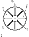
図7は、本発明の実施の形態1の送液ポンプ107の概略平面図である。
図8は、本発明の実施の形態の冷却装置100が利用されたパーソナルコンピュータの概略構成図である。
図9は、本発明の実施の形態の冷却装置200が利用されたパーソナルコンピュータの概略構成図である。
図10は、従来の投写型表示装置の概略構成図である。
図11は、従来の冷却装置の概略断面図である。FIG. 1 is a schematic configuration diagram of a projection display device using the cooling device according to the first embodiment of the present invention.
FIG. 2 is a schematic cross-sectional view of the cooling device according to the first embodiment of the present invention.
FIG. 3 is a schematic cross-sectional view of the cooling device according to the second embodiment of the present invention.
FIG. 4 is a schematic cross-sectional view of the cooling device according to the third embodiment of the present invention.
FIG. 5 is a schematic cross-sectional view of the cooling device according to the fourth embodiment of the present invention.
FIG. 6 is a schematic cross-sectional view of the cooling device according to the fifth embodiment of the present invention.
FIG. 7 is a schematic plan view of the
FIG. 8 is a schematic configuration diagram of a personal computer using the
FIG. 9 is a schematic configuration diagram of a personal computer using the
FIG. 10 is a schematic configuration diagram of a conventional projection display device.
FIG. 11 is a schematic cross-sectional view of a conventional cooling device.
4a、4b、4c 反射型映像素子
100 冷却装置
102 受熱プレート
103 受熱フレーム
105 電子冷却素子
106 液状材料
107 送液ポンプ
108、1108、2108、3108 受熱ケーシング
2108a 受熱部
110 液状媒体
111 開口部
112 入り口側の循環経路
112a 通路
114 放熱器
201 温度検出手段
202 温度制御手段
401 保持部材
403 駆動電気基板
404 押圧ホルダー
502、602 CPU4a, 4b, 4c
以下、本発明の実施の形態について図面を参照しながら説明する。
(実施の形態1)
はじめに、図1〜2を主として参照しながら、本実施の形態の冷却装置の構成を説明する。
図1は、本発明の実施の形態1の冷却装置が利用された投写型表示装置の概略構成図であり、図2は、本発明の実施の形態1の冷却装置の概略断面図である。
図1と図2において、図10と図11を用いて説明した従来の装置と同一構成部分には同一符号が附してあり、その部分は同様の機能であるため詳しい説明は省略する。
図2に示されているのは、発熱素子である反射型映像素子4c用の冷却装置であり、反射型映像素子4a、4bに対応する冷却装置も同一の機能を有する。
4a、4b、4cは、従来例と同様に色分離合成プリズムユニット5によって色分解された光である赤(R)、緑(G)、青(B)に対応する反射型映像素子である。
反射型映像素子4c部について説明すると、その反射型映像素子4cの受光面とは反対側の背面には、高熱伝導率を有する金属材料、例えば銅合金あるいは純アルミニューム等で形成された受熱プレート102が密着接合され、両者は熱的に面接合されている。
反射型映像素子4cの受光面側には、受光を妨げないように窓が設けられた、反射型映像素子4cへの駆動電力および駆動信号を供給するために駆動電気基板503が面接合されている。
103は、合成樹脂成形等から形成された方形枠状の受熱フレームであり、熱伝導率が受熱プレート102よりも小さい材料からなっている。
受熱プレート102と受熱フレーム103とは、受熱プレート102の外周縁が密閉(水密)接合されて一体的に組み付けられている。
この密閉接合は、例えばゴム製のOリング(図示せず)等を使用して行うことができる。
受熱プレート102と受熱フレーム103との組み付けにより、反射型映像素子4cの背面方向には、内容積を持つ容器形状が形成されている。
反射型映像素子4c側の外周縁には、枠状の位置決め部104が形成され、反射型映像素子4cの外周部が、位置決め部104によって概ね位置決めされている。
105は、一般的にペルチェ素子と呼ばれる電子冷却素子であり、受熱プレート102とは反対側で、その外周縁が受熱フレーム103に密閉(水密)的に接合固定されている。
この密閉的接合固定も、例えばゴム製のOリング(図示せず)等を使用して行うことができる。
106は、前記受熱プレート102と受熱フレーム103および電子冷却素子105によって密閉された空間内に充填された液状材料であり、例えばプロプレングリコール等のアルコール水溶液からなる。
従って、液状材料106と受熱プレート102とは、直接平面接触し、液状材料106と電子冷却素子105とも、直接平面接触して熱的接合されている。
107は、扁平形状の遠心ポンプからなる送液ポンプ(送液手段)であり、108は、送液ポンプ107のケーシングを兼ねる受熱ケーシングである。
受熱ケーシング108は、高熱伝導率の金属材料、例えばアルミニューム合金等で形成されており、その一方の扁平面は電子冷却素子105と平面でもって熱的に接合するように密着されている。
そして、受熱ケーシング108と受熱フレーム103とは、受熱フレーム103の外周縁に形成された位置決め部109によって位置決めされて、一体的に固定されている。
110は、送液ポンプ107によって循環され、熱量を移送する液状媒体であり、例えばプロプレングリコールのようなアルコール水溶液からなる。
送液ポンプ107の他方の扁平部には、モータ107aが設けられており、モータ軸107bには、ブレード107cが一体に固定されている。
112は、送液ポンプ107への液状媒体110の入口側の循環経路であり、113は、送液ポンプ107から液状媒体110が送出される出口側の循環経路である。
送液ポンプ107の入り口側の循環経路112は、送液ポンプ107のケーシングを兼ねる受熱ケーシング108の一方の扁平面側、すなわち電子冷却素子105側に配置されている。
そして、循環経路112には、受熱ケーシング108内を通るパイプ状の通路112aが形成され、その通路112aの開口端は、モータ107aにより回転されるブレード107cの回転中心に向けられている。
一方、送液ポンプ107から液状媒体110が送出される出口側循環経路113は、入り口側の循環経路112よりもモータ107aが配置された受熱ケーシング108の他方の扁平面側で、かつブレード107cの回転外周部と対向する位置に配置されている。
114は、放熱器であり、放熱器114の近傍には、放熱ファン115が設置されている。
送液ポンプ107の入り口側循環経路112と放熱器114および出口側循環経路113と放熱器114とは、それぞれ可撓性のホース116、117で接続されている。
液状媒体110は、送液ポンプ107、ホース116、117、放熱器114の内部に充満されており、モータ107aの駆動による送液ポンプ107のブレード107cの回転によって、受熱ケーシング108の入り口側循環経路112から吸引されて円周方向へと導かれ、出口側循環経路113を経て循環させられる。
つぎに、本実施の形態の冷却装置の動作を、本実施の形態の冷却装置が利用された投写型表示装置の冷却動作として説明する。
なお、本実施の形態の冷却装置の動作について説明しながら、本発明の冷却方法の一実施の形態についても説明する(その他の実施の形態についても、同様である)。
発熱体である反射型映像素子4cは、矢印方向(図2参照)から光を受け、有効に反射されない部分の存在によって発熱する。
反射型映像素子4cの光を受ける面とは反対側、すなわち背面側には、受熱プレート102が密着されており、この受熱プレート102が反射型映像素子4cの背面からその発熱を受熱する。
受熱プレート102は、液状材料106と接触しており、従って受熱プレート102からの熱量は液状材料106に伝達されることになる。
そして、電力が投入された電子冷却素子105は、液状材料106と接触する面を吸熱側とすることにより、液状材料106の熱量を直接吸熱して受熱プレート102を冷却する。
そして、受熱プレート102は、反射型映像素子4cを冷却する。
電子冷却素子105は、吸熱側とは反対側(図2上では右側)の面を放熱面とし、この放熱面からは、反射型映像素子4cからの熱量と電子冷却素子105自身の駆動電力により発生する熱量との合算の熱量が放熱されることになる。
電子冷却素子105の放熱面側には、送液ポンプ107のケーシングを兼ねる受熱ケーシング108が密着されているために、電子冷却素子105の放熱は、この受熱ケーシング108に伝達される。
そして、ブレード107cが、送液ポンプ107のモータ107aの駆動によって回転されるため、入り口側循環経路112から入り込んだ液状媒体110は、遠心方向に圧力がかかり、出口側循環経路113から送出されることになる。
受熱プレート102と電子冷却素子105との熱伝導にプロプレングリコールのようなアルコール水溶液等の液状材料106を介するようにしたため、境界部の低熱伝導性の欠点がなくなり、冷却効率が高められる。
一般的に、固体同士の接合部は、熱抵抗が大きく、熱伝導性が非常に悪いが、このような冷却装置においては、熱伝導が悪いと冷却効果が十分に得られない。
しかしながら、本実施の形態においては、液状媒体106が受熱プレート102および電子冷却素子105に直接接触して熱伝導がなされるため、固体同士の接合部にみられるような熱抵抗の増大がない。
従って、受熱プレート102から電子冷却素子105への熱伝導が極めて良好となり、冷却効率が向上するものである。
また、受熱ケーシング108においては、液状媒体110の入り口側の循環経路112が、電子冷却素子105と熱的に接合された一方の扁平面側に設けられている。
このため、放熱器114によって冷却された液状媒体110が、電子冷却素子105側から通路112aを通して送液ポンプ107に流入される。
かくして、冷却効率が向上する。
循環される液状媒体110は、放熱ファン115により冷却される放熱器114によって外部へ放熱、温度が低下して再び受熱ケーシング108内へ戻される。
これを繰り返すことによって、発熱体である反射型映像素子4cの熱量は、格段に高効率に放熱される。
もちろん、冷却装置は、反射型映像素子4a、4b側においても同様に構成されており、投写型表示装置全体の映像素子の高効率な冷却が、実現できるものである(その他の実施の形態においても、同様である)。
なお、受熱ケーシング108は本発明の受熱ケーシングに対応し、ホース116およびホース117を含む手段は本発明の循環経路に対応し、液状媒体110は本発明の液状媒体に対応し、送液ポンプ107は本発明のポンプに対応し、放熱器114および放熱ファン115を含む手段は本発明の冷却手段に対応する。
また、受熱プレート102は、本発明の受熱プレートに対応する。
また、電子冷却素子105は本発明の電子冷却素子に対応し、受熱フレーム103は本発明の受熱フレームに対応し、液状材料106は本発明の液状材料に対応する。
また、反射型映像素子4a、4b、4cは、本発明の反射型映像素子に対応する。
(実施の形態2)
はじめに、図3を主として参照しながら、本実施の形態の冷却装置の構成および動作について説明を行う。
図3は、本発明の実施の形態2の冷却装置の概略断面図である。
本実施の形態の冷却装置は、前述した実施の形態1の冷却装置に類似しているため、主としてこれらの相違点について説明する。
本実施の形態の冷却装置においては、電子冷却素子105と熱的接合している受熱ケーシング1108の接合ケース面(一方の扁平面)に複数個の開口部111が設けられている。
そして、開口部111を通して受熱ケーシング1108の内部を循環させられる液状媒体110が、電子冷却素子105に直接接触する。
複数個の開口部111は、それぞれ例えば円形状からなり、通路112aが位置する部分を除いてマトリクス状に配列されている。
そして、複数個の開口部111は、電子冷却素子105から液状媒体110への熱伝導を良好ならしめるために、電子冷却素子105と受熱ケーシング1108との接触面の面積に対して少なくとも1/3以上の総面積を有するように形成されている。
受熱ケーシング1108に複数個の開口部111を設けることにより、液状媒体110が電子冷却素子105に直接接触する。
そして、開口部111により受熱ケーシング1108の内面が複数の凹凸形状となるために、受熱ケーシング1108の内部、すなわち送液ポンプ107の内部で液状媒体110の循環流れに乱れが生じる。
熱伝導による温度境界層が、このような循環流れの乱れにより乱れて、電子冷却素子105から液状媒体110への熱伝達率、いわゆる熱の伝わり方が、格段に良くなり、冷却効率は、大幅に向上するものである。
なお、受熱ケーシング1108は、本発明の受熱ケーシングに対応する。
(実施の形態3)
はじめに、図4を主として参照しながら、本実施の形態の冷却装置の構成および動作について説明を行う。
図4は、本発明の実施の形態3の冷却装置の概略断面図である。
本実施の形態の冷却装置は、前述した実施の形態2の冷却装置に類似しているため、主としてこれらの相違点について説明する。
本実施の形態の冷却装置においては、温度制御が可能である。
具体的には、発熱体である反射型映像素子4cの温度を検出し、電気信号に変換するための温度検出手段201が、受熱プレート102に一体的に組込まれている。
そして、(a)温度検出手段201からの温度情報に応じて反射型映像素子4cを所望の温度に調整するために、電子冷却素子105の吸熱量と対応する駆動電力を調整するとともに、(b)送液ポンプ107によって循環される液状媒体110の送液量の調整のために、送液ポンプ107の駆動および放熱器114に対する放熱ファン115の駆動を最適状態に制御する温度制御手段202が、設けられている。
より具体的には、温度検出手段201によって検出される反射型映像素子4cの温度情報が温度制御手段202に入力され、送液ポンプ107の駆動力および放熱ファン115の駆動力が制御目標値に応じて制御され、電子冷却素子105の入力電力が調整される。
これにより、非常にきめ細かな温度制御が可能となり、過度の冷却による消費電力の増大を抑制することができる。
なお、温度検出手段201は本発明の検出手段に対応し、温度制御手段202は本発明の制御手段に対応する。
(実施の形態4)
はじめに、図5を主として参照しながら、本実施の形態の冷却装置の構成および動作について説明を行う。
図5は、本発明の実施の形態4の冷却装置の概略断面図である。
本実施の形態の冷却装置は、前述した実施の形態2の冷却装置に類似しているため、主としてこれらの相違点について説明する。
本実施の形態においては、反射型映像素子4cに接合された受熱プレート102に複数個の開口部111が設けられた受熱ケーシング3108が直接密着され、熱的接合させられている。
もちろん、受熱ケーシング3108の開口部111は、受熱プレート102により水密に構成されている。
なお、受熱プレート102と受熱ケーシング3108とは、受熱ケーシング3108に形成された位置決め部3108bにより相互に位置決めされている。
このような構成により、実施の形態2と同様に、複数個の開口部111によって、液状媒体110の循環流れに乱れが生じる。
そして、液状媒体110が直接受熱プレート102に接触するため、反射型映像素子4cの冷却効率が大幅に向上するものである。
なお、受熱ケーシング3108は、本発明の受熱ケーシングに対応する。
(実施の形態5)
はじめに、図6を主として参照しながら、本実施の形態の冷却装置の構成を説明する。
図6は、本発明の実施の形態5の冷却装置の概略断面図である。
本実施の形態の冷却装置は、前述した実施の形態4の冷却装置に類似しているため、主としてこれらの相違点について説明する。
401は、係止部401aを有し、係止部401aにより反射型映像素子4cを保持する枠状の保持部材である。
保持部材401の背面側には、反射型映像素子4cへの駆動電力および駆動信号を供給するために駆動電気基板403が面接合されている。
404は、駆動電気基板403の反射型映像素子4cの接合面とは反対側の面に面接合された剛性の高いアルミニューム合金等からなる押圧ホルダーである。
反射型映像素子4cと、駆動電気基板403と、押圧ホルダー404とは、保持部材401の端部に螺合された固定ネジ405によって固定され、一体化されている。
そして、反射型映像素子4cの端子と駆動電気基板403の端子とは、電気的に接続されている。
高熱伝導率の金属材料、例えばアルミニューム合金等で形成された送液ポンプ107のケーシングを兼ねる受熱ケーシング2108の反射型映像素子4cと対向する一方の扁平面側には、突台状の受熱部2108aが形成されている。
受熱部2108aは、押圧ホルダー404および駆動電気基板403の中央部にそれぞれ設けられた矩形状の孔(図示せず)に嵌合されて、位置決めされている。
そして、受熱ケーシング2108の受熱部2108aの先端扁平面は、反射型映像素子4cの背面に密着され、熱的接合されている。
つぎに、本実施の形態の冷却装置の動作を説明する。
反射型映像素子4cは、矢印方向から光を受け、有効に利用されない光のエネルギー成分によって発熱する。
反射型映像素子4cの発熱は、その背面に密着された受熱ケーシング2108の受熱部2108aに直接熱伝導される。
受熱ケーシング2108の内部には、液状媒体110が充填されており、熱伝導された受熱ケーシング2108の熱は、その内部の液状媒体110に伝達される。
送液ポンプ107によって液状媒体110が放熱器114との間で循環され、所望の冷却がなされることは、前述した実施の形態と同様である。
本実施の形態5においては、押圧ホルダー404および駆動電気基板403の中央部に窓を設け、これらの窓から受熱ケーシング2108の受熱部2108aを嵌合して反射型映像素子4cの背面と受熱ケーシング2108を直接面接触させるようにした。
このため、反射型映像素子4cに対する受熱ケーシング2108の位置決めが、前述の窓を基準として簡単に行えるものである。
なお、受熱ケーシング2108は、本発明の受熱ケーシングに対応する。
以上においては、実施の形態1〜5について詳細に説明を行った。
(1)なお、開口部111を設けた受熱ケーシング108は、送液ポンプ107のケーシングとは必ずしも兼ねる必要はなく、送液ポンプ107のケーシングは、ホース116またはホース117の途中に設けられていてもよい。
(2)また、液状媒体は、水であってもアルコールの水溶液であってもよい。
(3)また、媒体循環路はいわゆるホースであったが、ブチルゴムのような可撓性のあるゴムホースであればよりよい。
(4)また、ポンプ(送液手段)は、中央から吸引して円周方向に吐き出す遠心ポンプであったが、ダイヤフラムまたはピストンの往復運動で容積を変化させて一定量の液体を繰り返し押し出す容積ポンプであっても差し支えない。
なお、本発明の実施の形態1の送液ポンプ107の概略平面図である図7に示されているように、遠心ポンプが利用される場合には、紙面に関して垂直下向き(矢羽根の向き)に入り込んだ液状媒体110は、ブレード107cが回転されるため遠心方向に圧力がかかり、出口側循環経路113から送出されることになる。
(5)また、反射型映像素子、すなわち発熱体自身が熱伝導性のよいプレートを備えている場合は、別体としての受熱プレート102は、必ずしも必要ではない。
(6)また、受熱ケーシングの熱が導入される側の壁部には、複数個の開口部を設けた。しかし、これに限らず、大きい1つの開口部を設けてもよい。
もちろん、開口部の形状は、円形に限られるものではなく、方形状等その他の形状であってもよい。
また、複数個の開口部を設ける場合には、その配列は任意であってよい。
要するに、受熱ケーシングの熱が導入される側の内壁には、乱流を発生させるための凹凸部が設けられていてもよい。
(7)また、発熱体である反射型映像素子4cと受熱プレート102とは、直接接触させられていた。しかし、これに限らず、より熱伝導を向上させるためには、その接合部に熱伝導性グリース等が塗布された補助熱伝導部材を介在させてもよい。
もちろん、熱伝導性グリース等の補助熱伝導部材が、反射型映像素子4cと受熱ケーシング2108の受熱部2108aとの密着面に介在していてもよい。
(8)また、上述した実施の形態3においては、温度制御手段202により、送液ポンプ107による送液駆動条件と、放熱器114のための放熱ファン115の空冷駆動条件と、電子冷却素子105の吸熱量に応じた駆動条件とを制御するようにした。しかし、これに限らず、温度制御手段202により、送液ポンプ107の送液駆動条件、電子冷却素子105の駆動条件、放熱ファン115の空冷駆動条件の三つの条件の内の少なくとも一つが制御されればよい。
もちろん、反射型映像素子4cの温度状況に応じて、三つの条件の内の何れを制御するかが決定されてもよい。
また、このような制御は、上述した実施の形態の何れにおいても有効である。
(9)また、上述した実施の形態の冷却装置は、3板式の投写型表示装置において各反射型映像素子に対して備えることにより、同投写型表示装置の発熱体を高効率に冷却することができるものである。
もちろん、R、G、B用に3枚の反射型映像素子を使用する3板式投写型表示装置に限らず、モバイル装置等として市販されている、1枚の反射型映像素子を使用して時系列的にR、G、Bの色情報を作り出す単板式の投写型表示装置に、このような冷却装置を利用することも当然可能である。
さらに、上述した実施の形態の冷却装置は、投写型映像表示装置に限らず、パーソナルコンピュータのCPU、半導体レーザー等の熱制御が必要な電子機器の冷却装置として搭載することができるものである。
(9a)より具体的には、本発明の実施の形態の冷却装置100が利用されたパーソナルコンピュータの概略構成図である図8に示されているように、パーソナルコンピュータ等の電子機器のCPUを冷却することができる。
冷却装置100は、上述した本発明の実施の形態2の冷却装置と同様の構成を有している。
筐体500内の駆動電気基板501に取付けられた発熱体であるCPU502の表面には、冷却装置100が備えられており、受熱プレート102が、CPU502の放熱表面に熱的に接合されたものである。
放熱器114等は、上述した実施の形態2と同様である。
これによれば、反射型映像素子に代えてCPU502の発熱冷却を効率よく行えるものである。
なお、CPU502は、本発明のCPUに対応する。
(9b)また、本発明の実施の形態の冷却装置200が利用されたパーソナルコンピュータの概略構成図である図9に示されているように、パーソナルコンピュータ等の電子機器のCPUを冷却することができる。
冷却装置200は、上述した本発明の実施の形態3の冷却装置と同様の構成を有している。
筐体600内の駆動電気基板601に取付けられた発熱体であるCPU602の表面には、温度制御が可能な冷却装置200が備えられている。
すなわち、温度検出手段201を組み込んだ受熱プレート102が、CPU602の放熱表面に熱的に接合されたものである。
温度制御手段202や放熱器114等は、実施の形態3と同様である。
これによれば、温度制御手段202が、温度検出手段201によって検出されるCPU602の温度情報をもとに、送液ポンプ107、電子冷却素子105、放熱ファン(図示せず)を制御でき、制御目標値に沿った最適な冷却が行えるものである。
発熱体とその受熱部を放熱器114と離れて配置することにより、機器の筐体サイズを極めて薄くできるものである。
なお、CPU602は、本発明のCPUに対応する。
また、冷却が必要な発熱体は、パーソナルコンピュータCPUに限られるものではなく、その他の電子機器における半導体レーザー等の高出力な発熱量を有するレーザーダイオードやその他の発熱体であってもよい。
もちろん、放熱器114は、筐体中央部に設置される必要はなく、外部空気による放熱を利用してより良好な冷却を行うために、筐体の外部に近い部分に設置されてもよい。Hereinafter, embodiments of the present invention will be described with reference to the drawings.
(Embodiment 1)
First, the configuration of the cooling device of the present embodiment will be described with reference mainly to FIGS.
FIG. 1 is a schematic configuration diagram of a projection display device using the cooling device according to the first embodiment of the present invention, and FIG. 2 is a schematic sectional view of the cooling device according to the first embodiment of the present invention.
In FIG. 1 and FIG. 2, the same components as those in the conventional apparatus described with reference to FIG. 10 and FIG. 11 are denoted by the same reference numerals.
FIG. 2 shows a cooling device for the
The reflection
On the light receiving surface side of the reflection
The
This hermetic joining can be performed using, for example, a rubber O-ring (not shown).
By assembling the
A frame-shaped
This hermetic joining and fixing can also be performed using, for example, a rubber O-ring (not shown).
A
Therefore, the
The
The
A
112 is a circulation path on the inlet side of the
The
The
On the other hand, the outlet-
The inlet-
The
Next, the operation of the cooling device of the present embodiment will be described as the cooling operation of the projection display device using the cooling device of the present embodiment.
Note that while describing the operation of the cooling device of the present embodiment, an embodiment of the cooling method of the present invention will also be described (the same applies to other embodiments).
The
A
The
Then, the
The
The surface of the
Since the
Since the
Since the
In general, a joint portion between solids has a large thermal resistance and a very poor thermal conductivity. However, in such a cooling device, if the thermal conductivity is poor, a sufficient cooling effect cannot be obtained.
However, in the present embodiment, since the
Therefore, the heat conduction from the
Further, in the
For this reason, the
Thus, the cooling efficiency is improved.
The circulated
By repeating this, the amount of heat of the
Of course, the cooling device is configured in the same manner on the reflective image elements 4a and 4b side, and high-efficiency cooling of the image elements of the entire projection display device can be realized (in other embodiments). Is the same).
The
The
The
The
(Embodiment 2)
First, the configuration and operation of the cooling device of the present embodiment will be described with reference mainly to FIG.
FIG. 3 is a schematic cross-sectional view of the cooling device according to the second embodiment of the present invention.
Since the cooling device of the present embodiment is similar to the cooling device of the first embodiment described above, these differences will be mainly described.
In the cooling device of the present embodiment, a plurality of
Then, the
Each of the plurality of
The plurality of
By providing a plurality of
Since the inner surface of the
The temperature boundary layer due to heat conduction is disturbed by such disturbance of the circulation flow, so that the heat transfer rate from the
The
(Embodiment 3)
First, the configuration and operation of the cooling device of the present embodiment will be described with reference mainly to FIG.
FIG. 4 is a schematic cross-sectional view of the cooling device according to the third embodiment of the present invention.
Since the cooling device of the present embodiment is similar to the cooling device of the second embodiment described above, these differences will be mainly described.
In the cooling device of the present embodiment, temperature control is possible.
Specifically, temperature detecting means 201 for detecting the temperature of the reflection
(A) In order to adjust the
More specifically, the temperature information of the reflection
Thereby, very fine temperature control becomes possible, and increase in power consumption due to excessive cooling can be suppressed.
The
(Embodiment 4)
First, the configuration and operation of the cooling device of the present embodiment will be described with reference mainly to FIG.
FIG. 5 is a schematic cross-sectional view of the cooling device according to the fourth embodiment of the present invention.
Since the cooling device of the present embodiment is similar to the cooling device of the second embodiment described above, these differences will be mainly described.
In the present embodiment, a
Of course, the
Note that the
With such a configuration, similarly to the second embodiment, the circulation flow of the
Since the
The
(Embodiment 5)
First, the configuration of the cooling device of the present embodiment will be described with reference mainly to FIG.
FIG. 6 is a schematic cross-sectional view of the cooling device according to the fifth embodiment of the present invention.
Since the cooling device according to the present embodiment is similar to the cooling device according to the fourth embodiment described above, the differences will be mainly described.
On the back side of the holding
The
The terminals of the
On one flat surface side of the
The heat receiving portion 2108a is positioned by being fitted into rectangular holes (not shown) provided in the central portions of the
The flat end surface of the heat receiving portion 2108a of the
Next, the operation of the cooling device of the present embodiment will be described.
The
The heat generated by the
The
The
In the fifth embodiment, a window is provided in the central portion of the
For this reason, the positioning of the
The
The first to fifth embodiments have been described in detail above.
(1) The
(2) The liquid medium may be water or an aqueous solution of alcohol.
(3) Although the medium circulation path is a so-called hose, it is better if it is a flexible rubber hose such as butyl rubber.
(4) The pump (liquid feeding means) is a centrifugal pump that sucks in from the center and discharges it in the circumferential direction. However, the volume is changed by reciprocating the diaphragm or piston to repeatedly push out a certain amount of liquid. It can be a pump.
In addition, as shown in FIG. 7 which is a schematic plan view of the
(5) Further, when the reflective image element, that is, the heating element itself is provided with a plate having good thermal conductivity, the separate
(6) Further, a plurality of openings are provided in the wall portion of the heat receiving casing where heat is introduced. However, the present invention is not limited to this, and one large opening may be provided.
Of course, the shape of the opening is not limited to a circle, but may be other shapes such as a square shape.
Moreover, when providing several opening part, the arrangement | sequence may be arbitrary.
In short, an uneven portion for generating turbulent flow may be provided on the inner wall of the heat receiving casing where heat is introduced.
(7) In addition, the
Of course, an auxiliary heat conducting member such as a heat conducting grease may be interposed on the contact surface between the
(8) Further, in the above-described third embodiment, the
Of course, it may be determined which of the three conditions is controlled according to the temperature state of the
Such control is effective in any of the above-described embodiments.
(9) In addition, the cooling device of the above-described embodiment is provided for each reflective image element in a three-plate projection display device, thereby cooling the heating element of the projection display device with high efficiency. It is something that can be done.
Of course, the present invention is not limited to the three-plate projection display device using three reflective image elements for R, G, and B, but using one reflective image element commercially available as a mobile device or the like. It is naturally possible to use such a cooling device for a single-plate projection display device that generates R, G, B color information in series.
Furthermore, the cooling device of the above-described embodiment is not limited to a projection display device, and can be mounted as a cooling device for an electronic device that requires thermal control, such as a CPU of a personal computer or a semiconductor laser.
(9a) More specifically, as shown in FIG. 8 which is a schematic configuration diagram of a personal computer using the
The
The
The
According to this, the heat generation and cooling of the
The
(9b) Further, as shown in FIG. 9 which is a schematic configuration diagram of a personal computer using the
The
A
That is, the
The
According to this, the
By disposing the heating element and its heat receiving portion away from the
The
Further, the heating element that needs to be cooled is not limited to the personal computer CPU, and may be a laser diode having a high heat generation amount, such as a semiconductor laser in other electronic devices, or other heating elements.
Of course, the
本発明の冷却装置は、たとえば、投写型表示装置の映像素子、パーソナルコンピュータのCPU、半導体レーザー装置の半導体レーザー等をより効率よく冷却することができ、有用である。 The cooling device of the present invention is useful because it can more efficiently cool, for example, an image element of a projection display device, a CPU of a personal computer, a semiconductor laser of a semiconductor laser device, and the like.
本発明は、たとえば、画像を投写レンズによりスクリーン上に拡大投写する投写型表示装置、パーソナルコンピュータ、半導体レーザー装置等の電子機器に利用可能な、筐体内部に配設された半導体やCPUなどの発熱電子部品を液状媒体を循環させて冷却または温度制御する冷却装置に関するものである。 The present invention is applicable to, for example, a semiconductor or a CPU disposed in a housing, which can be used in an electronic apparatus such as a projection display device that enlarges and projects an image on a screen using a projection lens, a personal computer, and a semiconductor laser device. The present invention relates to a cooling device that cools or controls the temperature of a heat generating electronic component by circulating a liquid medium.
ノートタイプのパーソナルコンピュータや移動体通信機器に代表される携帯型の電子機器は、マルチメディア情報を処理するためのマイクロプロセッサを装備している。 Portable electronic devices typified by notebook personal computers and mobile communication devices are equipped with a microprocessor for processing multimedia information.
この種のマイクロプロセッサは、演算速度の高速化や多機能化に伴い、動作中の発熱量が急速に増大する傾向がある。 This type of microprocessor tends to rapidly increase the amount of heat generated during operation as the calculation speed increases and the number of functions increases.
そのため、マイクロプロセッサの動作を安定的に保証するためには、その発熱量に見合う冷却性を高める必要がある。 Therefore, in order to stably guarantee the operation of the microprocessor, it is necessary to improve the cooling performance corresponding to the heat generation amount.
また、半導体レーザー光源装置に代表される電子機器は、高出力化やビームの波長安定性確保の観点から、発振源となる半導体を適当な温度に温度制御する必要がある。 In addition, in an electronic device represented by a semiconductor laser light source device, it is necessary to control the temperature of a semiconductor serving as an oscillation source to an appropriate temperature from the viewpoint of increasing the output and ensuring the beam wavelength stability.
また、近年の小型化の要望のため、その温度制御装置の小型化と高い温度制御性能が、要求されるようになってきている。 Further, due to the recent demand for miniaturization, miniaturization of the temperature control device and high temperature control performance have been demanded.
また、ライトバルブ上で映像信号に変調された画像を照明光で照射し、投写レンズによりスクリーン上にその画像を拡大投写する投写型表示装置に代表される表示装置においては、画像情報をより鮮明に投影するために高解像度のライトバルブからなる映像素子が用いられ、さらに投影画面の明るい高輝度化が促進されている。 In a display device typified by a projection display device that irradiates an image modulated with a video signal on a light valve with illumination light and enlarges and projects the image on a screen by a projection lens, the image information becomes clearer. In order to project the image on the screen, an image element composed of a high-resolution light valve is used.
また、高輝度が求められる投写型表示装置の映像素子は、原理的には入射される光量に対し、有効にスクリーンに投影されない成分等の光による熱量を吸収するため、映像素子の発熱が、輝度アップの制限となっている。 In addition, the image element of a projection display device that requires high luminance, in principle, absorbs the amount of heat due to light such as a component that is not effectively projected on the screen with respect to the amount of incident light. The brightness is limited.
その対策として、映像素子は透過型液晶表示素子に代わって、液晶等による反射型映像素子が使用されるようになってきている。 As a countermeasure, a reflection type image element using liquid crystal or the like has been used instead of a transmission type liquid crystal display element.
反射型映像素子であっても僅かの光吸収が発生するために、この反射型映像素子を強制的に冷却する必要がある。 Even in the case of a reflection type image element, slight light absorption occurs, and therefore it is necessary to forcibly cool the reflection type image element.
このため反射型映像素子を精度よく位置決めする調整機構と、この反射型映像素子を強制冷却するための冷却素子と、その冷却素子の放熱側を冷却するヒートシンクおよびそのヒートシンクを空冷する冷却ファンとが一体となった冷却装置が、利用されるようになってきている。 Therefore, there are an adjustment mechanism for accurately positioning the reflective image element, a cooling element for forcibly cooling the reflective image element, a heat sink for cooling the heat radiation side of the cooling element, and a cooling fan for air cooling the heat sink. Integrated cooling devices are becoming available.
以下、電子機器や表示装置の熱対策に関する従来の技術について、より具体的に説明する。 Hereinafter, a conventional technique related to heat countermeasures for electronic devices and display devices will be described more specifically.
ここでは、一般的な反射型映像素子を用いた投写型表示装置の冷却装置を例として説明する。 Here, a cooling device for a projection display device using a general reflection type image element will be described as an example.
投写型表示装置の光学系は、基本的に、光源ランプユニットと、その光源ランプユニットの光源からの白色光を赤(R)、緑(G)、青(B)に色分解し、これらの光を画像情報に応じて変調する反射型液晶パネル等から構成された映像素子と、その変調された光を色合成する光学ユニットと、その色合成された光をスクリーン上に拡大投影する投写レンズユニットとで構成されている。 The optical system of the projection display device basically separates the light source lamp unit and white light from the light source of the light source lamp unit into red (R), green (G), and blue (B) An image element composed of a reflective liquid crystal panel or the like that modulates light according to image information, an optical unit that synthesizes the color of the modulated light, and a projection lens that enlarges and projects the color-synthesized light on a screen It consists of units.
最近では、投写型表示装置においては、画像情報をより鮮明に投影するために高解像度の映像素子が用いられてきており、さらに投影画面の明るい高輝度化が促進されていることは、上述したとおりである。 Recently, in a projection display apparatus, a high-resolution image element has been used to project image information more clearly, and further, brighter and brighter projection screens have been promoted. It is as follows.
従来のR、G、Bの各反射型映像素子を用いた3板式投写型表示装置とその冷却装置について、図10と図11を用いてその一例を説明する。 An example of a conventional three-plate projection display apparatus using R, G, and B reflection type image elements and its cooling apparatus will be described with reference to FIGS.
まず、図10は、従来の投写型表示装置の概略構成を示す図である。 First, FIG. 10 is a diagram showing a schematic configuration of a conventional projection display apparatus.
従来の投写型表示装置は、画像情報を光学的に拡大投影するための光源である光源ランプユニット1と、その光源ランプユニット1の光から赤外線や紫外線を除去し、可視光のみを透過するためのフィルター2と、そのフィルター2からの可視光を集光するための照射光学ユニット3と、前記照射光学ユニット3で集光された光が反射プリズムユニット6を通過した後、これを色分解して反射型映像素子4a、4b、4cに導くとともに、この反射型映像素子4a、4b、4cで光学的に画像情報に生成された光を色合成する色分離合成プリズムユニット5と、前記色分離合成プリズムユニット5で合成された画像情報が前記反射プリズムユニット6で反射されてこれを拡大投射するための投写レンズユニット7とで構成されている。
A conventional projection display apparatus removes infrared rays and ultraviolet rays from light from a light source lamp unit 1 that is a light source for optically enlarging and projecting image information, and transmits only visible light. The
光源ランプユニット1は、一般的に発光効率が高いとされる超高圧水銀ランプ1aと、光を効率よく集光するための凹面鏡1bで構成されている。
The light source lamp unit 1 is composed of an ultra-high pressure mercury lamp 1a generally having high luminous efficiency and a
光源ランプユニット1からの光をR、G、Bに色分解および色合成する色分離合成プリズムユニット5は、例えば白色光を波長的に選択する青反射ダイクロイックミラーと、赤反射ダイクロイックミラーと、緑透過のダイクロイックミラーで構成される。
A color separation /
そして、各々の膜特性から白色光は、R、G、Bに色分解されて、各R、G、Bの反射型映像素子4a、4b、4cへ導かれるとともに、その反射型映像素子4a、4b、4cで画像情報に変調された光は、再び色分離合成プリズムユニット5で合成される。
The white light is color-separated into R, G, and B from each film characteristic and led to the R, G, and B
反射プリズムユニット6は、照射光学ユニット3からの光を透過するとともに色分離合成プリズムユニット5で色合成された光を投写レンズユニット7に導く、いわゆる、ハーフミラー構成の一体型プリズムである。
The reflecting prism unit 6 is a so-called half-mirror-integrated prism that transmits light from the irradiation optical unit 3 and guides the light synthesized by the color separation /
図11は、従来の反射型映像素子の冷却装置を示す概略断面図である。 FIG. 11 is a schematic cross-sectional view showing a conventional cooling device for a reflective image element.
なお、この図11では、反射型映像素子4c部分のみを示しているが、反射型映像素子4aと4b部分についても同様の構成となっている。
In FIG. 11, only the reflection
反射型映像素子4cは、一方の面が、平面的位置調整やフォーカス調整が可能な位置調整機構8に接着剤等で接合固定されており、位置調整機構8は、色分離合成プリズムユニット5に対接あるいは接着剤等で正確に位置決め固定されている。
One surface of the
また、反射型映像素子4cの他方の面は、半導体で構成された電子冷却素子9に熱伝導としての役目も果たすホルダー10を介して接合されている。
The other surface of the reflection
電子冷却素子9には、その放熱のためのヒートシンク11が接合され、ヒートシンク11には、これを冷却するための冷却ファン12が接合されている。
A
そして、この冷却ファン12とヒートシンク11とホルダー10は、ネジ等(図示なし)で一体的に組み立てられている。
The cooling
しかしながら、上記のような従来の冷却装置では、より高輝度を目指した投写型表示装置の場合、反射型映像素子4a、4b、4cにより多くの光が集中するため、冷却性能を向上させる必要がある。
However, in the conventional cooling device as described above, in the case of a projection display device aiming at higher luminance, a lot of light is concentrated on the
そのため、より大きな能力を有する電子冷却素子9、ヒートシンク11、冷却ファン12が必要となり、これは装置の大型化のみならず、重量増加を招くことになる。
Therefore, the electronic cooling element 9, the
また、この冷却装置は、電子冷却素子9の吸熱量に見合った消費電力による発熱量と反射型映像素子の発熱量との合計発熱量を放熱する必要があるため、冷却ファン12が想像以上に大型化する。
Further, since this cooling device needs to dissipate the total heat generation amount of the heat generation amount due to the power consumption corresponding to the heat absorption amount of the electronic cooling element 9 and the heat generation amount of the reflective image element, the cooling
また、冷却ファン12は、ヒートシンク11に接合しているために、通風抵抗が過大となって送風騒音が大きくなることもある。
Moreover, since the cooling
さらに、電子冷却素子9の吸熱量を大きくした場合、熱伝導部材として機能するホルダー10は、電子冷却素子9の接合部側が雰囲気温度よりも大きく低温側となり、このため結露が発生することもある。
Further, when the heat absorption amount of the electronic cooling element 9 is increased, in the
また、冷却ファン12の構造上、その中央部は、冷却ファン12のモータ駆動部のためにヒートシンク11の外周部のみ図面の矢印のように通風冷却され、ヒートシンク11の冷却効率を悪化させやすい。
Further, due to the structure of the cooling
一方、放熱経路で見ると、反射型映像素子4cとホルダー10との間、ホルダー10と電子冷却素子9との間、および電子冷却素子9とヒートシンク11との間で、3カ所の部材接合部が存在する。
On the other hand, when viewed from the heat dissipation path, there are three member joints between the
このため、熱移動のインピーダンス、すなわち熱抵抗が非常に大きくなり、放熱能力を非常に大きく設計しなければならないことが普通であった。 For this reason, the impedance of heat transfer, that is, the thermal resistance becomes very large, and it is usual that the heat radiation capacity must be designed very large.
さらに、近年の投写型表示装置の高輝度化に伴い、光源ランプユニットの駆動電力も大きくなってきている。 Furthermore, with the recent increase in the brightness of projection display devices, the driving power of the light source lamp unit has also increased.
電子冷却素子9の吸熱能力は、一般的に50%未満である。 The endothermic capacity of the electronic cooling element 9 is generally less than 50%.
このため、電子冷却素子9は、反射型映像素子4cの発熱量の2倍から6倍の電力を要し、消費電力が、極めて大きなものとなっている。
For this reason, the electronic cooling element 9 requires 2 to 6 times the amount of heat generated by the
本発明は、上記従来のこのような課題を考慮し、たとえば、投写型表示装置の映像素子、パーソナルコンピュータのCPU、半導体レーザー装置の半導体レーザー等をより効率よく冷却することができる冷却装置を提供することを目的とする。 In view of the above-described conventional problems, the present invention provides a cooling device capable of more efficiently cooling, for example, an image element of a projection display device, a CPU of a personal computer, a semiconductor laser of a semiconductor laser device, and the like. The purpose is to do.
第1の本発明は、発熱体と直接的にまたは間接的に熱的接合される受熱ケーシングと、
前記受熱ケーシングの内部と連通された循環経路と、
前記受熱ケーシングの内部、および前記循環経路に充填された液状媒体と、
前記充填された液状媒体を循環させる、前記受熱ケーシングの内部に設けられたポンプと、
前記循環させられる液状媒体を冷却する冷却手段とを備えた、冷却装置である。
A first aspect of the present invention is a heat receiving casing that is directly or indirectly thermally bonded to a heating element;
A circulation path communicating with the interior of the heat receiving casing;
A liquid medium filled in the heat receiving casing and in the circulation path;
A pump provided inside the heat receiving casing for circulating the filled liquid medium;
And a cooling device that cools the circulated liquid medium.
第2の本発明は、前記循環させられる液状媒体が前記循環経路から前記受熱ケーシングに流入する流入口は、前記受熱ケーシングの、前記受熱ケーシングが前記発熱体と直接的にまたは間接的に熱的接合される側に設けられている第1の本発明の、冷却装置である。 According to a second aspect of the present invention, the inflow port through which the circulated liquid medium flows into the heat receiving casing from the circulation path is directly or indirectly thermally connected to the heat generating casing. It is a cooling device of the 1st present invention provided in the side joined.
第3の本発明は、前記ポンプは、回転されるブレードを有する遠心ポンプであって、
前記流入口は、前記回転されるブレードの回転中心の近傍に設けられている第2の本発明の、冷却装置である。
According to a third aspect of the present invention, the pump is a centrifugal pump having a rotating blade,
The inflow port is the cooling device according to the second aspect of the present invention, which is provided in the vicinity of the rotation center of the rotating blade.
第4の本発明は、前記受熱ケーシングは、前記発熱体と直接的にまたは間接的に熱的接合される側に凹凸部が設けられた内壁を有する第1の本発明の、冷却装置である。 The fourth aspect of the present invention is the cooling device according to the first aspect of the present invention, wherein the heat receiving casing has an inner wall provided with a concavo-convex portion on a side that is directly or indirectly thermally bonded to the heating element. .
第5の本発明は、前記発熱体を駆動するための駆動電気基板が、前記発熱体の、前記受熱ケーシングが直接的にまたは間接的に熱的接合される側に配置されている第1から第4の何れかの本発明の、冷却装置である。 According to a fifth aspect of the present invention, from the first aspect, a driving electric board for driving the heating element is disposed on a side of the heating element where the heat receiving casing is directly or indirectly thermally bonded. 4 is a cooling device according to any one of the present inventions.
第6の本発明は、前記駆動電気基板を前記発熱体に対して押圧するための押圧ホルダーが、前記駆動電気基板の、前記受熱ケーシングが直接的にまたは間接的に熱的接合される側に配置されている第5の本発明の、冷却装置である。 According to a sixth aspect of the present invention, there is provided a pressing holder for pressing the driving electric board against the heating element, on the side of the driving electric board where the heat receiving casing is directly or indirectly thermally bonded. It is the cooling device of 5th this invention arrange | positioned.
第7の本発明は、前記駆動電気基板は、駆動電気基板窓を有しており、
前記押圧ホルダーは、前記駆動電気基板窓と重なる位置に押圧ホルダー窓を有しており、
前記受熱ケーシングは、前記駆動電気基板窓と前記押圧ホルダー窓とを貫通して、前記発熱体に当接する受熱部を有する請求項6記載の、冷却装置である。
In a seventh aspect of the present invention, the drive electric board has a drive electric board window,
The pressing holder has a pressing holder window at a position overlapping the driving electric board window,
The said heat receiving casing is a cooling device of Claim 6 which has a heat receiving part which penetrates the said drive electric board | substrate window and the said press holder window, and contact | abuts to the said heat generating body.
第8の本発明は、前記発熱体と接合される受熱プレートをさらに備えた第1から第4の何れかの本発明の、冷却装置である。 The eighth aspect of the present invention is the cooling device according to any one of the first to fourth aspects of the present invention, further comprising a heat receiving plate joined to the heating element.
第9の本発明は、前記受熱ケーシングと接合された電子冷却素子と、
前記受熱プレートと前記電子冷却素子との間に密閉空間を形成する受熱フレームと、
前記密閉空間に充填された液状材料とをさらに備えた第8の本発明の、冷却装置である。
The ninth aspect of the present invention is an electronic cooling element joined to the heat receiving casing;
A heat receiving frame that forms a sealed space between the heat receiving plate and the electronic cooling element;
The cooling device according to an eighth aspect of the present invention, further comprising a liquid material filled in the sealed space.
第10の本発明は、前記発熱体の温度を検出する検出手段と、
前記検出の結果に基づいて、前記ポンプ、および前記冷却手段の内の少なくとも一つを制御する制御手段とをさらに備えた第1から第4の何れかの本発明の、冷却装置である。
A tenth aspect of the present invention is a detection means for detecting the temperature of the heating element;
The cooling device according to any one of the first to fourth aspects of the present invention, further comprising: a control unit that controls at least one of the pump and the cooling unit based on the detection result.
第11の本発明は、第1の本発明の、冷却装置と、
前記発熱体としての反射型映像素子とを備えた投写型表示装置である。
The eleventh aspect of the present invention is the cooling device according to the first aspect of the present invention,
A projection display device comprising a reflective image element as the heating element.
第12の本発明は、第1の本発明の、冷却装置と、
前記発熱体としての、半導体、およびCPUの内の少なくとも一つとを備えた電子機器である。
The twelfth aspect of the present invention is the cooling device of the first aspect of the present invention,
An electronic apparatus including at least one of a semiconductor and a CPU as the heating element.
第13の本発明は、反射型映像素子、半導体、およびCPUの内の少なくとも一つと直接的にまたは間接的に熱的接合される受熱ケーシングと、
前記受熱ケーシングの内部と連通された循環経路と、
前記受熱ケーシングの内部、および前記循環経路に充填された液状媒体と、
前記充填された液状媒体を循環させるポンプと、
前記循環させられる液状媒体を冷却する冷却手段とを備えた冷却装置である。
A thirteenth aspect of the present invention is a heat receiving casing that is directly or indirectly thermally bonded to at least one of a reflective image element, a semiconductor, and a CPU;
A circulation path communicating with the interior of the heat receiving casing;
A liquid medium filled in the heat receiving casing and in the circulation path;
A pump for circulating the filled liquid medium;
And a cooling device that cools the circulated liquid medium.
第14の本発明は、発熱体と直接的にまたは間接的に熱的接合される受熱ケーシングの内部、および前記受熱ケーシングの内部と連通された循環経路に充填された液状媒体を、前記受熱ケーシングの内部に設けられたポンプを利用して循環させる循環ステップと、
前記循環させられる液状媒体を冷却する冷却ステップとを備えた冷却方法である。
According to a fourteenth aspect of the present invention, a liquid medium filled in a heat receiving casing that is directly or indirectly thermally bonded to a heating element and a circulation path that is in communication with the heat receiving casing is used as the heat receiving casing. A circulation step to circulate using a pump provided in the interior,
And a cooling step for cooling the circulated liquid medium.
本発明は、投写型表示装置の映像素子、パーソナルコンピュータのCPU、半導体レーザー装置等の電子機器をより効率よく冷却することができるという長所を有する。 The present invention has an advantage that electronic devices such as a video element of a projection display device, a CPU of a personal computer, and a semiconductor laser device can be cooled more efficiently.
本発明の冷却装置は、たとえば、投写型表示装置の映像素子、パーソナルコンピュータのCPU、半導体レーザー装置の半導体レーザー等をより効率よく冷却することができ、有用である。 The cooling device of the present invention is useful because it can more efficiently cool, for example, an image element of a projection display device, a CPU of a personal computer, a semiconductor laser of a semiconductor laser device, and the like.
以下、本発明の実施の形態について図面を参照しながら説明する。 Hereinafter, embodiments of the present invention will be described with reference to the drawings.
(実施の形態1)
はじめに、図1〜2を主として参照しながら、本実施の形態の冷却装置の構成を説明する。
(Embodiment 1)
First, the configuration of the cooling device of the present embodiment will be described with reference mainly to FIGS.
図1は、本発明の実施の形態1の冷却装置が利用された投写型表示装置の概略構成図であり、図2は、本発明の実施の形態1の冷却装置の概略断面図である。 FIG. 1 is a schematic configuration diagram of a projection display device using the cooling device according to the first embodiment of the present invention, and FIG. 2 is a schematic sectional view of the cooling device according to the first embodiment of the present invention.
図1と図2において、図10と図11を用いて説明した従来の装置と同一構成部分には同一符号が附してあり、その部分は同様の機能であるため詳しい説明は省略する。 In FIG. 1 and FIG. 2, the same components as those in the conventional apparatus described with reference to FIG. 10 and FIG. 11 are denoted by the same reference numerals.
図2に示されているのは、発熱素子である反射型映像素子4c用の冷却装置であり、反射型映像素子4a、4bに対応する冷却装置も同一の機能を有する。
FIG. 2 shows a cooling device for the
4a、4b、4cは、従来例と同様に色分離合成プリズムユニット5によって色分解された光である赤(R)、緑(G)、青(B)に対応する反射型映像素子である。
反射型映像素子4c部について説明すると、その反射型映像素子4cの受光面とは反対側の背面には、高熱伝導率を有する金属材料、例えば銅合金あるいは純アルミニューム等で形成された受熱プレート102が密着接合され、両者は熱的に面接合されている。
The reflection
反射型映像素子4cの受光面側には、受光を妨げないように窓が設けられた、反射型映像素子4cへの駆動電力および駆動信号を供給するために駆動電気基板503が面接合されている。
On the light receiving surface side of the reflection
103は、合成樹脂成形等から形成された方形枠状の受熱フレームであり、熱伝導率が受熱プレート102よりも小さい材料からなっている。
受熱プレート102と受熱フレーム103とは、受熱プレート102の外周縁が密閉(水密)接合されて一体的に組み付けられている。
The
この密閉接合は、例えばゴム製のOリング(図示せず)等
を使用して行うことができる。
This hermetic joining can be performed using, for example, a rubber O-ring (not shown).
受熱プレート102と受熱フレーム103との組み付けにより、反射型映像素子4cの背面方向には、内容積を持つ容器形状が形成されている。
By assembling the
反射型映像素子4c側の外周縁には、枠状の位置決め部104が形成され、反射型映像素子4cの外周部が、位置決め部104によって概ね位置決めされている。
A frame-shaped
105は、一般的にペルチェ素子と呼ばれる電子冷却素子であり、受熱プレート102とは反対側で、その外周縁が受熱フレーム103に密閉(水密)的に接合固定されている。
この密閉的接合固定も、例えばゴム製のOリング(図示せず)等を使用して行うことができる。 This hermetic joining and fixing can also be performed using, for example, a rubber O-ring (not shown).
106は、前記受熱プレート102と受熱フレーム103および電子冷却素子105によって密閉された空間内に充填された液状材料であり、例えばプロプレングリコール等のアルコール水溶液からなる。
A
従って、液状材料106と受熱プレート102とは、直接平面接触し、液状材料106と電子冷却素子105とも、直接平面接触して熱的接合されている。
Therefore, the
107は、扁平形状の遠心ポンプからなる送液ポンプ(送液手段)であり、108は、送液ポンプ107のケーシングを兼ねる受熱ケーシングである。
受熱ケーシング108は、高熱伝導率の金属材料、例えばアルミニューム合金等で形成されており、その一方の扁平面は電子冷却素子105と平面でもって熱的に接合するように密着されている。
The
そして、受熱ケーシング108と受熱フレーム103とは、受熱フレーム103の外周縁に形成された位置決め部109によって位置決めされて、一体的に固定されている。
The
110は、送液ポンプ107によって循環され、熱量を移送する液状媒体であり、例えばプロプレングリコールのようなアルコール水溶液からなる。
送液ポンプ107の他方の扁平部には、モータ107aが設けられており、モータ軸107bには、ブレード107cが一体に固定されている。
A
112は、送液ポンプ107への液状媒体110の入口側の循環経路であり、113は、送液ポンプ107から液状媒体110が送出される出口側の循環経路である。
112 is a circulation path on the inlet side of the
送液ポンプ107の入り口側の循環経路112は、送液ポンプ107のケーシングを兼ねる受熱ケーシング108の一方の扁平面側、すなわち電子冷却素子105側に配置されている。
The
そして、循環経路112には、受熱ケーシング108内を通るパイプ状の通路112aが形成され、その通路112aの開口端は、モータ107aにより回転されるブレード107cの回転中心に向けられている。
The
一方、送液ポンプ107から液状媒体110が送出される出口側循環経路113は、入り口側の循環経路112よりもモータ107aが配置された受熱ケーシング108の他方の扁平面側で、かつブレード107cの回転外周部と対向する位置に配置されている。
On the other hand, the outlet-
114は、放熱器であり、放熱器114の近傍には、放熱ファン115が設置されている。
送液ポンプ107の入り口側循環経路112と放熱器114および出口側循環経路113と放熱器114とは、それぞれ可撓性のホース116、117で接続されている。
The inlet-
液状媒体110は、送液ポンプ107、ホース116、117、放熱器114の内部に充満されており、モータ107aの駆動による送液ポンプ107のブレード107cの回転によって、受熱ケーシング108の入り口側循環経路112から吸引されて円周方向へと導かれ、出口側循環経路113を経て循環させられる。
The
つぎに、本実施の形態の冷却装置の動作を、本実施の形態の冷却装置が利用された投写型表示装置の冷却動作として説明する。 Next, the operation of the cooling device of the present embodiment will be described as the cooling operation of the projection display device using the cooling device of the present embodiment.
なお、本実施の形態の冷却装置の動作について説明しながら、本発明の冷却方法の一実施の形態についても説明する(その他の実施の形態についても、同様である)。 Note that while describing the operation of the cooling device of the present embodiment, an embodiment of the cooling method of the present invention will also be described (the same applies to other embodiments).
発熱体である反射型映像素子4cは、矢印方向(図2参照)から光を受け、有効に反射されない部分の存在によって発熱する。
The
反射型映像素子4cの光を受ける面とは反対側、すなわち背面側には、受熱プレート102が密着されており、この受熱プレート102が反射型映像素子4cの背面からその発熱を受熱する。
A
受熱プレート102は、液状材料106と接触しており、従って受熱プレート102からの熱量は液状材料106に伝達されることになる。
The
そして、電力が投入された電子冷却素子105は、液状材料106と接触する面を吸熱側とすることにより、液状材料106の熱量を直接吸熱して受熱プレート102を冷却する。
Then, the
そして、受熱プレート102は、反射型映像素子4cを冷却する。
The
電子冷却素子105は、吸熱側とは反対側(図2上では右側)の面を放熱面とし、この放熱面からは、反射型映像素子4cからの熱量と電子冷却素子105自身の駆動電力により発生する熱量との合算の熱量が放熱されることになる。
The surface of the
電子冷却素子105の放熱面側には、送液ポンプ107のケーシングを兼ねる受熱ケーシング108が密着されているために、電子冷却素子105の放熱は、この受熱ケーシング108に伝達される。
Since the
そして、ブレード107cが、送液ポンプ107のモータ107aの駆動によって回転されるため、入り口側循環経路112から入り込んだ液状媒体110は、遠心方向に圧力がかかり、出口側循環経路113から送出されることになる。
Since the
受熱プレート102と電子冷却素子105との熱伝導にプロプレングリコールのようなアルコール水溶液等の液状材料106を介するようにしたため、境界部の低熱伝導性の欠点がなくなり、冷却効率が高められる。
Since the
一般的に、固体同士の接合部は、熱抵抗が大きく、熱伝導性が非常に悪いが、このような冷却装置においては、熱伝導が悪いと冷却効果が十分に得られない。 In general, a joint portion between solids has a large thermal resistance and a very poor thermal conductivity. However, in such a cooling device, if the thermal conductivity is poor, a sufficient cooling effect cannot be obtained.
しかしながら、本実施の形態においては、液状媒体106が受熱プレート102および電子冷却素子105に直接接触して熱伝導がなされるため、固体同士の接合部にみられるような熱抵抗の増大がない。
However, in the present embodiment, since the
従って、受熱プレート102から電子冷却素子105への熱伝導が極めて良好となり、冷却効率が向上するものである。
Therefore, the heat conduction from the
また、受熱ケーシング108においては、液状媒体110の入り口側の循環経路112が、電子冷却素子105と熱的に接合された一方の扁平面側に設けられている。
Further, in the
このため、放熱器114によって冷却された液状媒体110が、電子冷却素子105側から通路112aを通して送液ポンプ107に流入される。
For this reason, the
かくして、冷却効率が向上する。 Thus, the cooling efficiency is improved.
循環される液状媒体110は、放熱ファン115により冷却される放熱器114によって外部へ放熱、温度が低下して再び受熱ケーシング108内へ戻される。
The circulated
これを繰り返すことによって、発熱体である反射型映像素子4cの熱量は、格段に高効率に放熱される。
By repeating this, the amount of heat of the
もちろん、冷却装置は、反射型映像素子4a、4b側においても同様に構成されており、投写型表示装置全体の映像素子の高効率な冷却が、実現できるものである(その他の実施の形態においても、同様である)。 Of course, the cooling device is configured in the same manner on the reflective image elements 4a and 4b side, and high-efficiency cooling of the image elements of the entire projection display device can be realized (in other embodiments). Is the same).
なお、受熱ケーシング108は本発明の受熱ケーシングに対応し、ホース116およびホース117を含む手段は本発明の循環経路に対応し、液状媒体110は本発明の液状媒体に対応し、送液ポンプ107は本発明のポンプに対応し、放熱器114および放熱ファン115を含む手段は本発明の冷却手段に対応する。
The
また、受熱プレート102は、本発明の受熱プレートに対応する。
The
また、電子冷却素子105は本発明の電子冷却素子に対応し、受熱フレーム103は本発明の受熱フレームに対応し、液状材料106は本発明の液状材料に対応する。
The
また、反射型映像素子4a、4b、4cは、本発明の反射型映像素子に対応する。
The
(実施の形態2)
はじめに、図3を主として参照しながら、本実施の形態の冷却装置の構成および動作について説明を行う。
(Embodiment 2)
First, the configuration and operation of the cooling device of the present embodiment will be described with reference mainly to FIG.
図3は、本発明の実施の形態2の冷却装置の概略断面図である。 FIG. 3 is a schematic cross-sectional view of the cooling device according to the second embodiment of the present invention.
本実施の形態の冷却装置は、前述した実施の形態1の冷却装置に類似しているため、主としてこれらの相違点について説明する。 Since the cooling device of the present embodiment is similar to the cooling device of the first embodiment described above, these differences will be mainly described.
本実施の形態の冷却装置においては、電子冷却素子105と熱的接合している受熱ケーシング1108の接合ケース面(一方の扁平面)に複数個の開口部111が設けられている。
In the cooling device of the present embodiment, a plurality of
そして、開口部111を通して受熱ケーシング1108の内部を循環させられる液状媒体110が、電子冷却素子105に直接接触する。
Then, the
複数個の開口部111は、それぞれ例えば円形状からなり、通路112aが位置する部分を除いてマトリクス状に配列されている。
Each of the plurality of
そして、複数個の開口部111は、電子冷却素子105から液状媒体110への熱伝導を良好ならしめるために、電子冷却素子105と受熱ケーシング1108との接触面の面積に対して少なくとも1/3以上の総面積を有するように形成されている。
The plurality of
受熱ケーシング1108に複数個の開口部111を設けることにより、液状媒体110が電子冷却素子105に直接接触する。
By providing a plurality of
そして、開口部111により受熱ケーシング1108の内面が複数の凹凸形状となるために、受熱ケーシング1108の内部、すなわち送液ポンプ107の内部で液状媒体110の循環流れに乱れが生じる。
Since the inner surface of the
熱伝導による温度境界層が、このような循環流れの乱れにより乱れて、電子冷却素子105から液状媒体110への熱伝達率、いわゆる熱の伝わり方が、格段に良くなり、冷却効率は、大幅に向上するものである。
The temperature boundary layer due to heat conduction is disturbed by such disturbance of the circulation flow, so that the heat transfer rate from the
なお、受熱ケーシング1108は、本発明の受熱ケーシングに対応する。
The
(実施の形態3)
はじめに、図4を主として参照しながら、本実施の形態の冷却装置の構成および動作について説明を行う。
(Embodiment 3)
First, the configuration and operation of the cooling device of the present embodiment will be described with reference mainly to FIG.
図4は、本発明の実施の形態3の冷却装置の概略断面図である。 FIG. 4 is a schematic cross-sectional view of the cooling device according to the third embodiment of the present invention.
本実施の形態の冷却装置は、前述した実施の形態2の冷却装置に類似しているため、主としてこれらの相違点について説明する。 Since the cooling device of the present embodiment is similar to the cooling device of the second embodiment described above, these differences will be mainly described.
本実施の形態の冷却装置においては、温度制御が可能である。 In the cooling device of the present embodiment, temperature control is possible.
具体的には、発熱体である反射型映像素子4cの温度を検出し、電気信号に変換するための温度検出手段201が、受熱プレート102に一体的に組込まれている。
Specifically, temperature detecting means 201 for detecting the temperature of the reflection
そして、(a)温度検出手段201からの温度情報に応じて反射型映像素子4cを所望の温度に調整するために、電子冷却素子105の吸熱量と対応する駆動電力を調整するとともに、(b)送液ポンプ107によって循環される液状媒体110の送液量の調整のために、送液ポンプ107の駆動および放熱器114に対する放熱ファン115の駆動を最適状態に制御する温度制御手段202が、設けられている。
(A) In order to adjust the
より具体的には、温度検出手段201によって検出される反射型映像素子4cの温度情報が温度制御手段202に入力され、送液ポンプ107の駆動力および放熱ファン115の駆動力が制御目標値に応じて制御され、電子冷却素子105の入力電力が調整される。
More specifically, the temperature information of the reflection
これにより、非常にきめ細かな温度制御が可能となり、過度の冷却による消費電力の増大を抑制することができる。 Thereby, very fine temperature control becomes possible, and increase in power consumption due to excessive cooling can be suppressed.
なお、温度検出手段201は本発明の検出手段に対応し、温度制御手段202は本発明の制御手段に対応する。
The
(実施の形態4)
はじめに、図5を主として参照しながら、本実施の形態の冷却装置の構成および動作について説明を行う。
(Embodiment 4)
First, the configuration and operation of the cooling device of the present embodiment will be described with reference mainly to FIG.
図5は、本発明の実施の形態4の冷却装置の概略断面図である。 FIG. 5 is a schematic cross-sectional view of the cooling device according to the fourth embodiment of the present invention.
本実施の形態の冷却装置は、前述した実施の形態2の冷却装置に類似しているため、主としてこれらの相違点について説明する。 Since the cooling device of the present embodiment is similar to the cooling device of the second embodiment described above, these differences will be mainly described.
本実施の形態においては、反射型映像素子4cに接合された受熱プレート102に複数個の開口部111が設けられた受熱ケーシング3108が直接密着され、熱的接合させられている。
In the present embodiment, a
もちろん、受熱ケーシング3108の開口部111は、受熱プレート102により水密に構成されている。
Of course, the
なお、受熱プレート102と受熱ケーシング3108とは、受熱ケーシング3108に形成された位置決め部3108bにより相互に位置決めされている。
Note that the
このような構成により、実施の形態2と同様に、複数個の開口部111によって、液状媒体110の循環流れに乱れが生じる。
With such a configuration, similarly to the second embodiment, the circulation flow of the
そして、液状媒体110が直接受熱プレート102に接触するため、反射型映像素子4cの冷却効率が大幅に向上するものである。
Since the
なお、受熱ケーシング3108は、本発明の受熱ケーシングに対応する。
The
(実施の形態5)
はじめに、図6を主として参照しながら、本実施の形態の冷却装置の構成を説明する。
(Embodiment 5)
First, the configuration of the cooling device of the present embodiment will be described with reference mainly to FIG.
図6は、本発明の実施の形態5の冷却装置の概略断面図である。 FIG. 6 is a schematic cross-sectional view of the cooling device according to the fifth embodiment of the present invention.
本実施の形態の冷却装置は、前述した実施の形態4の冷却装置に類似しているため、主としてこれらの相違点について説明する。 Since the cooling device according to the present embodiment is similar to the cooling device according to the fourth embodiment described above, the differences will be mainly described.
401は、係止部401aを有し、係止部401aにより反射型映像素子4cを保持する枠状の保持部材である。
保持部材401の背面側には、反射型映像素子4cへの駆動電力および駆動信号を供給するために駆動電気基板403が面接合されている。
On the back side of the holding
404は、駆動電気基板403の反射型映像素子4cの接合面とは反対側の面に面接合された剛性の高いアルミニューム合金等からなる押圧ホルダーである。
反射型映像素子4cと、駆動電気基板403と、押圧ホルダー404とは、保持部材401の端部に螺合された固定ネジ405によって固定され、一体化されている。
The
そして、反射型映像素子4cの端子と駆動電気基板403の端子とは、電気的に接続されている。
The terminals of the
高熱伝導率の金属材料、例えばアルミニューム合金等で形成された送液ポンプ107のケーシングを兼ねる受熱ケーシング2108の反射型映像素子4cと対向する一方の扁平面側には、突台状の受熱部2108aが形成されている。
On one flat surface side of the
受熱部2108aは、押圧ホルダー404および駆動電気基板403の中央部にそれぞれ設けられた矩形状の孔(図示せず)に嵌合されて、位置決めされている。
The heat receiving portion 2108a is positioned by being fitted into rectangular holes (not shown) provided in the central portions of the
そして、受熱ケーシング2108の受熱部2108aの先端扁平面は、反射型映像素子4cの背面に密着され、熱的接合されている。
The flat end surface of the heat receiving portion 2108a of the
つぎに、本実施の形態の冷却装置の動作を説明する。 Next, the operation of the cooling device of the present embodiment will be described.
反射型映像素子4cは、矢印方向から光を受け、有効に利用されない光のエネルギー成分によって発熱する。
The
反射型映像素子4cの発熱は、その背面に密着された受熱ケーシング2108の受熱部2108aに直接熱伝導される。
The heat generated by the
受熱ケーシング2108の内部には、液状媒体110が充填されており、熱伝導された受熱ケーシング2108の熱は、その内部の液状媒体110に伝達される。
The
送液ポンプ107によって液状媒体110が放熱器114との間で循環され、所望の冷却がなされることは、前述した実施の形態と同様である。
The
本実施の形態5においては、押圧ホルダー404および駆動電気基板403の中央部に窓を設け、これらの窓から受熱ケーシング2108の受熱部2108aを嵌合して反射型映像素子4cの背面と受熱ケーシング2108を直接面接触させるようにした。
In the fifth embodiment, a window is provided in the central portion of the
このため、反射型映像素子4cに対する受熱ケーシング2108の位置決めが、前述の窓を基準として簡単に行えるものである。
For this reason, the positioning of the
なお、受熱ケーシング2108は、本発明の受熱ケーシングに対応する。
The
以上においては、実施の形態1〜5について詳細に説明を行った。 The first to fifth embodiments have been described in detail above.
(1)なお、開口部111を設けた受熱ケーシング108は、送液ポンプ107のケーシングとは必ずしも兼ねる必要はなく、送液ポンプ107のケーシングは、ホース116またはホース117の途中に設けられていてもよい。
(1) The
(2)また、液状媒体は、水であってもアルコールの水溶液であってもよい。 (2) The liquid medium may be water or an aqueous solution of alcohol.
(3)また、媒体循環路はいわゆるホースであったが、ブチルゴムのような可撓性のあるゴムホースであればよりよい。 (3) Although the medium circulation path is a so-called hose, it is better if it is a flexible rubber hose such as butyl rubber.
(4)また、ポンプ(送液手段)は、中央から吸引して円周方向に吐き出す遠心ポンプであったが、ダイヤフラムまたはピストンの往復運動で容積を変化させて一定量の液体を繰り返し押し出す容積ポンプであっても差し支えない。 (4) The pump (liquid feeding means) is a centrifugal pump that sucks in from the center and discharges it in the circumferential direction. However, the volume is changed by reciprocating the diaphragm or piston to repeatedly push out a certain amount of liquid. It can be a pump.
なお、本発明の実施の形態1の送液ポンプ107の概略平面図である図7に示されているように、遠心ポンプが利用される場合には、紙面に関して垂直下向き(矢羽根の向き)に入り込んだ液状媒体110は、ブレード107cが回転されるため遠心方向に圧力がかかり、出口側循環経路113から送出されることになる。
In addition, as shown in FIG. 7 which is a schematic plan view of the
(5)また、反射型映像素子、すなわち発熱体自身が熱伝導性のよいプレートを備えている場合は、別体としての受熱プレート102は、必ずしも必要ではない。
(5) Further, when the reflective image element, that is, the heating element itself is provided with a plate having good thermal conductivity, the separate
(6)また、受熱ケーシングの熱が導入される側の壁部には、複数個の開口部を設けた。しかし、これに限らず、大きい1つの開口部を設けてもよい。 (6) Further, a plurality of openings are provided in the wall portion of the heat receiving casing where heat is introduced. However, the present invention is not limited to this, and one large opening may be provided.
もちろん、開口部の形状は、円形に限られるものではなく、方形状等その他の形状であってもよい。 Of course, the shape of the opening is not limited to a circle, but may be other shapes such as a square shape.
また、複数個の開口部を設ける場合には、その配列は任意であってよい。 Moreover, when providing several opening part, the arrangement | sequence may be arbitrary.
要するに、受熱ケーシングの熱が導入される側の内壁には、乱流を発生させるための凹凸部が設けられていてもよい。 In short, an uneven portion for generating turbulent flow may be provided on the inner wall of the heat receiving casing where heat is introduced.
(7)また、発熱体である反射型映像素子4cと受熱プレート102とは、直接接触させられていた。しかし、これに限らず、より熱伝導を向上させるためには、その接合部に熱伝導性グリース等が塗布された補助熱伝導部材を介在させてもよい。
(7) In addition, the
もちろん、熱伝導性グリース等の補助熱伝導部材が、反射型映像素子4cと受熱ケーシング2108の受熱部2108aとの密着面に介在していてもよい。
Of course, an auxiliary heat conducting member such as a heat conducting grease may be interposed on the contact surface between the
(8)また、上述した実施の形態3においては、温度制御手段202により、送液ポンプ107による送液駆動条件と、放熱器114のための放熱ファン115の空冷駆動条件と、電子冷却素子105の吸熱量に応じた駆動条件とを制御するようにした。しかし、これに限らず、温度制御手段202により、送液ポンプ107の送液駆動条件、電子冷却素子105の駆動条件、放熱ファン115の空冷駆動条件の三つの条件の内の少なくとも一つが制御されればよい。
(8) Further, in the above-described third embodiment, the
もちろん、反射型映像素子4cの温度状況に応じて、三つの条件の内の何れを制御するかが決定されてもよい。
Of course, it may be determined which of the three conditions is controlled according to the temperature state of the
また、このような制御は、上述した実施の形態の何れにおいても有効である。 Such control is effective in any of the above-described embodiments.
(9)また、上述した実施の形態の冷却装置は、3板式の投写型表示装置において各反射型映像素子に対して備えることにより、同投写型表示装置の発熱体を高効率に冷却することができるものである。 (9) In addition, the cooling device of the above-described embodiment is provided for each reflective image element in a three-plate projection display device, thereby cooling the heating element of the projection display device with high efficiency. It is something that can be done.
もちろん、R、G、B用に3枚の反射型映像素子を使用する3板式投写型表示装置に限らず、モバイル装置等として市販されている、1枚の反射型映像素子を使用して時系列的にR、G、Bの色情報を作り出す単板式の投写型表示装置に、このような冷却装置を利用することも当然可能である。 Of course, the present invention is not limited to the three-plate projection display device using three reflective image elements for R, G, and B, but using one reflective image element commercially available as a mobile device or the like. It is naturally possible to use such a cooling device for a single-plate projection display device that generates R, G, B color information in series.
さらに、上述した実施の形態の冷却装置は、投写型映像表示装置に限らず、パーソナルコンピュータのCPU、半導体レーザー等の熱制御が必要な電子機器の冷却装置として搭載することができるものである。 Furthermore, the cooling device of the above-described embodiment is not limited to a projection display device, and can be mounted as a cooling device for an electronic device that requires thermal control, such as a CPU of a personal computer or a semiconductor laser.
(9a)より具体的には、本発明の実施の形態の冷却装置100が利用されたパーソナルコンピュータの概略構成図である図8に示されているように、パーソナルコンピュータ等の電子機器のCPUを冷却することができる。
(9a) More specifically, as shown in FIG. 8 which is a schematic configuration diagram of a personal computer using the
冷却装置100は、上述した本発明の実施の形態2の冷却装置と同様の構成を有している。
The
筐体500内の駆動電気基板501に取付けられた発熱体であるCPU502の表面には、冷却装置100が備えられており、受熱プレート102が、CPU502の放熱表面に熱的に接合されたものである。
The
放熱器114等は、上述した実施の形態2と同様である。
The
これによれば、反射型映像素子に代えてCPU502の発熱冷却を効率よく行えるものである。
According to this, the heat generation and cooling of the
なお、CPU502は、本発明のCPUに対応する。
The
(9b)また、本発明の実施の形態の冷却装置200が利用されたパーソナルコンピュータの概略構成図である図9に示されているように、パーソナルコンピュータ等の電子機器のCPUを冷却することができる。
(9b) Further, as shown in FIG. 9 which is a schematic configuration diagram of a personal computer using the
冷却装置200は、上述した本発明の実施の形態3の冷却装置と同様の構成を有している。
The
筐体600内の駆動電気基板601に取付けられた発熱体であるCPU602の表面には、温度制御が可能な冷却装置200が備えられている。
A
すなわち、温度検出手段201を組み込んだ受熱プレート102が、CPU602の放熱表面に熱的に接合されたものである。
That is, the
温度制御手段202や放熱器114等は、実施の形態3と同様である。
The
これによれば、温度制御手段202が、温度検出手段201によって検出されるCPU602の温度情報をもとに、送液ポンプ107、電子冷却素子105、放熱ファン(図示せず)を制御でき、制御目標値に沿った最適な冷却が行えるものである。
According to this, the
発熱体とその受熱部を放熱器114と離れて配置することにより、機器の筐体サイズを極めて薄くできるものである。
By disposing the heating element and its heat receiving portion away from the
なお、CPU602は、本発明のCPUに対応する。
The
また、冷却が必要な発熱体は、パーソナルコンピュータCPUに限られるものではなく、その他の電子機器における半導体レーザー等の高出力な発熱量を有するレーザーダイオードやその他の発熱体であってもよい。 Further, the heating element that needs to be cooled is not limited to the personal computer CPU, and may be a laser diode having a high heat generation amount, such as a semiconductor laser in other electronic devices, or other heating elements.
もちろん、放熱器114は、筐体中央部に設置される必要はなく、外部空気による放熱を利用してより良好な冷却を行うために、筐体の外部に近い部分に設置されてもよい。
Of course, the
本発明にかかる冷却装置は、たとえば、投写型表示装置の映像素子、パーソナルコンピュータのCPU、半導体レーザー装置の半導体レーザー等をより効率よく冷却することができるという効果を有し、画像を投写レンズによりスクリーン上に拡大投写する投写型表示装置、パーソナルコンピュータ、半導体レーザー装置等の電子機器に利用可能な、筐体内部に配設された半導体やCPUなどの発熱電子部品を液状媒体を循環させて冷却または温度制御する冷却装置等に有用である。 The cooling device according to the present invention has an effect that the image element of the projection display device, the CPU of the personal computer, the semiconductor laser of the semiconductor laser device, and the like can be cooled more efficiently. Cooling heat-generating electronic components such as semiconductors and CPUs installed inside the housing that can be used in electronic devices such as projection display devices, personal computers, and semiconductor laser devices that project images on the screen by circulating a liquid medium It is also useful for a cooling device that controls temperature.
4a、4b、4c 反射型映像素子
100 冷却装置
102 受熱プレート
103 受熱フレーム
105 電子冷却素子
106 液状材料
107 送液ポンプ
108、1108、2108、3108 受熱ケーシング
2108a 受熱部
110 液状媒体
111 開口部
112 入り口側の循環経路
112a 通路
114 放熱器
201 温度検出手段
202 温度制御手段
401 保持部材
403 駆動電気基板
404 押圧ホルダー
502、602 CPU
4a, 4b, 4c
Claims (12)
前記受熱ケーシングの内部と連通された循環経路と、
前記受熱ケーシングの内部、および前記循環経路に充填された液状媒体と、
前記充填された液状媒体を循環させる、前記受熱ケーシングの内部に設けられたポンプと、
前記循環させられる液状媒体を冷却する冷却手段とを備えた、冷却装置。A heat receiving casing that is directly or indirectly thermally joined to the heating element;
A circulation path communicating with the interior of the heat receiving casing;
A liquid medium filled in the heat receiving casing and in the circulation path;
A pump provided inside the heat receiving casing for circulating the filled liquid medium;
A cooling device comprising cooling means for cooling the circulated liquid medium.
前記流入口は、前記回転されるブレードの回転中心の近傍に設けられている請求の範囲第2項記載の、冷却装置。The pump is a centrifugal pump having a rotating blade,
The cooling device according to claim 2, wherein the inflow port is provided in the vicinity of a rotation center of the rotated blade.
前記押圧ホルダーは、前記駆動電気基板窓と重なる位置に押圧ホルダー窓を有しており、
前記受熱ケーシングは、前記駆動電気基板窓と前記押圧ホルダー窓とを貫通して、前記発熱体に当接する受熱部を有する請求の範囲第6項記載の、冷却装置。The drive electrical board has a drive electrical board window;
The pressing holder has a pressing holder window at a position overlapping the driving electric board window,
The cooling device according to claim 6, wherein the heat receiving casing includes a heat receiving portion that passes through the drive electric board window and the pressing holder window and contacts the heating element.
前記受熱プレートと前記電子冷却素子との面に密閉空間を形成する受熱フレームと、
前記密閉空間に充填された液状材料とをさらに備えた請求の範囲第8項記載の、冷却装置。An electronic cooling element joined to the heat receiving casing;
A heat receiving frame that forms a sealed space on the surfaces of the heat receiving plate and the electronic cooling element;
The cooling device according to claim 8, further comprising a liquid material filled in the sealed space.
前記検出の結果に基づいて、前記ポンプ、および前記冷却手段の内の少なくとも一つを制御する制御手段とをさらに備えた請求の範囲第1項から第4項の何れかに記載の、冷却装置。Detecting means for detecting the temperature of the heating element;
The cooling device according to any one of claims 1 to 4, further comprising: a control unit that controls at least one of the pump and the cooling unit based on a result of the detection. .
前記発熱体としての反射型映像素子とを備えた投写型表示装置。A cooling device according to claim 1;
A projection display device comprising a reflective image element as the heating element.
前記発熱体としての、半導体、およびCPUの内の少なくとも一つとを備えた電子機器。A cooling device according to claim 1;
An electronic apparatus comprising at least one of a semiconductor and a CPU as the heating element.
Applications Claiming Priority (3)
| Application Number | Priority Date | Filing Date | Title |
|---|---|---|---|
| JP2003155045 | 2003-05-30 | ||
| JP2003155045 | 2003-05-30 | ||
| PCT/JP2004/007793 WO2004107837A1 (en) | 2003-05-30 | 2004-05-28 | Cooling device |
Publications (2)
| Publication Number | Publication Date |
|---|---|
| JPWO2004107837A1 true JPWO2004107837A1 (en) | 2006-07-20 |
| JP4559361B2 JP4559361B2 (en) | 2010-10-06 |
Family
ID=33487346
Family Applications (1)
| Application Number | Title | Priority Date | Filing Date |
|---|---|---|---|
| JP2005506582A Expired - Lifetime JP4559361B2 (en) | 2003-05-30 | 2004-05-28 | Projection display |
Country Status (4)
| Country | Link |
|---|---|
| US (1) | US7264359B2 (en) |
| JP (1) | JP4559361B2 (en) |
| CN (1) | CN100531534C (en) |
| WO (1) | WO2004107837A1 (en) |
Families Citing this family (49)
| Publication number | Priority date | Publication date | Assignee | Title |
|---|---|---|---|---|
| US7971632B2 (en) | 2003-11-07 | 2011-07-05 | Asetek A/S | Cooling system for a computer system |
| JP3966288B2 (en) * | 2004-01-28 | 2007-08-29 | セイコーエプソン株式会社 | Light modulation element holder, optical device, and projector |
| US20060044524A1 (en) * | 2004-08-31 | 2006-03-02 | Feliss Norbert A | System and method for cooling a beam projector |
| US7124811B2 (en) | 2004-12-31 | 2006-10-24 | Intel Corporation | Systems for integrated pump and cold plate |
| KR100688978B1 (en) * | 2005-04-21 | 2007-03-08 | 삼성전자주식회사 | Projection device |
| TWI301722B (en) * | 2005-04-28 | 2008-10-01 | Benq Corp | Water-cooled projector |
| US20060245214A1 (en) * | 2005-04-29 | 2006-11-02 | Kim Won-Nyun | Liquid crystal display having heat dissipation device |
| CN101228495B (en) | 2005-05-06 | 2013-03-13 | 阿塞泰克公司 | Cooling system for computer system |
| US20060279706A1 (en) * | 2005-06-14 | 2006-12-14 | Bash Cullen E | Projection system |
| KR100628726B1 (en) * | 2005-07-26 | 2006-09-28 | 삼성전자주식회사 | Projection device |
| US7249625B2 (en) * | 2005-08-03 | 2007-07-31 | Cooler Master Co., Ltd. | Water-cooling heat dissipation device |
| JP4196983B2 (en) * | 2005-10-07 | 2008-12-17 | セイコーエプソン株式会社 | COOLING DEVICE, PROJECTOR, AND COOLING METHOD |
| TWI328997B (en) * | 2006-08-21 | 2010-08-11 | Delta Electronics Inc | Cooling module for use with a projection apparatus |
| WO2009008166A1 (en) * | 2007-07-12 | 2009-01-15 | Panasonic Corporation | Image display device |
| US9453691B2 (en) * | 2007-08-09 | 2016-09-27 | Coolit Systems, Inc. | Fluid heat exchange systems |
| US9496200B2 (en) | 2011-07-27 | 2016-11-15 | Coolit Systems, Inc. | Modular heat-transfer systems |
| US9943014B2 (en) | 2013-03-15 | 2018-04-10 | Coolit Systems, Inc. | Manifolded heat exchangers and related systems |
| US8746330B2 (en) | 2007-08-09 | 2014-06-10 | Coolit Systems Inc. | Fluid heat exchanger configured to provide a split flow |
| JP2009086273A (en) * | 2007-09-28 | 2009-04-23 | Sanyo Electric Co Ltd | Light source element for projection type video display device and projection type video display device equipped with light source unit constituted of light source element |
| KR20090046301A (en) * | 2007-11-05 | 2009-05-11 | 삼성전기주식회사 | Monocrystalline substrate manufacturing method and solar cell manufacturing method using same |
| US20090161078A1 (en) * | 2007-12-21 | 2009-06-25 | Oculon Optoelectronics, Inc. | Projector, and mobile device and computer device having the same |
| CN101546105B (en) * | 2008-03-24 | 2010-11-10 | 精工爱普生株式会社 | Projector |
| JP4561917B2 (en) | 2008-03-24 | 2010-10-13 | セイコーエプソン株式会社 | projector |
| EP2273308A4 (en) | 2008-03-28 | 2014-04-02 | Nec Display Solutions Ltd | Projection image display unit |
| TWM347014U (en) * | 2008-07-04 | 2008-12-11 | yi-fang Zhuang | Handheld electronic device with micro projection module |
| JP2011033747A (en) * | 2009-07-31 | 2011-02-17 | Seiko Epson Corp | Projector, program, information storage medium and cooling control method |
| CN102042573B (en) * | 2009-10-23 | 2013-01-23 | 陈定平 | Semiconductor illumination light-heat separated type circulating radiating system with controllable temperature and street lamp |
| CN102056459A (en) * | 2009-10-30 | 2011-05-11 | 鸿富锦精密工业(深圳)有限公司 | Liquid-cooling heat radiating device |
| JP5880998B2 (en) * | 2010-09-16 | 2016-03-09 | 株式会社リコー | Cooling device, image forming apparatus |
| TW201223426A (en) | 2010-11-25 | 2012-06-01 | Delta Electronics Inc | Cooling system for cooling a heat source and projector having the same |
| US10365667B2 (en) | 2011-08-11 | 2019-07-30 | Coolit Systems, Inc. | Flow-path controllers and related systems |
| WO2014141162A1 (en) | 2013-03-15 | 2014-09-18 | Coolit Systems, Inc. | Sensors, multiplexed communication techniques, and related systems |
| JP2013167774A (en) * | 2012-02-16 | 2013-08-29 | Mitsubishi Electric Corp | Multi-screen display device |
| US12366870B2 (en) | 2013-03-15 | 2025-07-22 | Coolit Systems, Inc. | Flow-path controllers and related systems |
| CN105135365A (en) * | 2013-04-25 | 2015-12-09 | 深圳市光峰光电技术有限公司 | Wavelength conversion device and related light-emitting device |
| US10415597B2 (en) | 2014-10-27 | 2019-09-17 | Coolit Systems, Inc. | Fluid heat exchange systems |
| KR102392820B1 (en) * | 2015-05-21 | 2022-05-02 | 주식회사 브라이트론 | The Cooling Fan cooled by Cooling Effect of its Surface of the Spindle Fan Blade |
| US11249522B2 (en) | 2016-06-30 | 2022-02-15 | Intel Corporation | Heat transfer apparatus for a computer environment |
| JP6743625B2 (en) * | 2016-09-29 | 2020-08-19 | セイコーエプソン株式会社 | Wavelength conversion device, light source device, and projector |
| JP7046656B2 (en) * | 2017-03-15 | 2022-04-04 | キヤノン株式会社 | Image projection device |
| US12152606B2 (en) * | 2017-03-28 | 2024-11-26 | Faizan Ahmed | Thermo-electric chiller/heater component methods and systems |
| US11452243B2 (en) | 2017-10-12 | 2022-09-20 | Coolit Systems, Inc. | Cooling system, controllers and methods |
| US11662037B2 (en) | 2019-01-18 | 2023-05-30 | Coolit Systems, Inc. | Fluid flow control valve for fluid flow systems, and methods |
| US11473860B2 (en) | 2019-04-25 | 2022-10-18 | Coolit Systems, Inc. | Cooling module with leak detector and related systems |
| CN111856855B (en) * | 2019-04-29 | 2022-02-22 | 中强光电股份有限公司 | Optical machine module and projector |
| US11395443B2 (en) | 2020-05-11 | 2022-07-19 | Coolit Systems, Inc. | Liquid pumping units, and related systems and methods |
| US11725886B2 (en) | 2021-05-20 | 2023-08-15 | Coolit Systems, Inc. | Modular fluid heat exchange systems |
| US12200914B2 (en) | 2022-01-24 | 2025-01-14 | Coolit Systems, Inc. | Smart components, systems and methods for transferring heat |
| CN115022521B (en) * | 2022-07-09 | 2024-01-30 | 浙江舜宇智领技术有限公司 | Camera module |
Citations (9)
| Publication number | Priority date | Publication date | Assignee | Title |
|---|---|---|---|---|
| JPH0832263A (en) * | 1994-07-20 | 1996-02-02 | Fujitsu Ltd | Heater package cooling structure |
| JP2001015662A (en) * | 1999-06-30 | 2001-01-19 | Nippon Keiki Works Ltd | Cooling system |
| JP2001183042A (en) * | 1999-12-24 | 2001-07-06 | Isuzu Ceramics Res Inst Co Ltd | Cooling device for electric parts by circulation of coolant |
| WO2002019027A1 (en) * | 2000-08-28 | 2002-03-07 | Matsushita Electric Industrial Co., Ltd. | Projection video device |
| JP2002151638A (en) * | 2000-11-08 | 2002-05-24 | Hitachi Ltd | Electronic equipment cooling device |
| JP2002174795A (en) * | 2000-09-20 | 2002-06-21 | Barco Nv | Projector device having spatial light modulation unit and cooling method thereof |
| JP2004134423A (en) * | 2002-10-08 | 2004-04-30 | Hitachi Ltd | Electronic equipment cooling device |
| JP2004183646A (en) * | 2002-09-13 | 2004-07-02 | Oliver Laing | Equipment for local cooling or heating of objects |
| JP2005338715A (en) * | 2004-05-31 | 2005-12-08 | Nec Viewtechnology Ltd | Video display element cooling structure and projection type optical apparatus |
Family Cites Families (6)
| Publication number | Priority date | Publication date | Assignee | Title |
|---|---|---|---|---|
| CN1306609C (en) * | 1998-09-18 | 2007-03-21 | 三菱电机株式会社 | Semiconductor power conversion device |
| JP4017775B2 (en) * | 1998-12-28 | 2007-12-05 | 富士通株式会社 | Projection display |
| JP2001110955A (en) * | 1999-10-04 | 2001-04-20 | Meiden Chem Kk | Heat dissipating members and heat dissipating electronic components |
| JP2001320187A (en) | 2000-02-29 | 2001-11-16 | Matsushita Electric Ind Co Ltd | Liquid cooling device for electronic components |
| JP4397114B2 (en) * | 2000-09-12 | 2010-01-13 | 日本サーモスタット株式会社 | Electronic equipment cooling device |
| TW567742B (en) * | 2001-03-22 | 2003-12-21 | Ind Tech Res Inst | Cooling apparatus of liquid crystal projector |
-
2004
- 2004-05-28 US US10/547,012 patent/US7264359B2/en not_active Expired - Lifetime
- 2004-05-28 CN CN200480005435.XA patent/CN100531534C/en not_active Expired - Lifetime
- 2004-05-28 JP JP2005506582A patent/JP4559361B2/en not_active Expired - Lifetime
- 2004-05-28 WO PCT/JP2004/007793 patent/WO2004107837A1/en not_active Ceased
Patent Citations (9)
| Publication number | Priority date | Publication date | Assignee | Title |
|---|---|---|---|---|
| JPH0832263A (en) * | 1994-07-20 | 1996-02-02 | Fujitsu Ltd | Heater package cooling structure |
| JP2001015662A (en) * | 1999-06-30 | 2001-01-19 | Nippon Keiki Works Ltd | Cooling system |
| JP2001183042A (en) * | 1999-12-24 | 2001-07-06 | Isuzu Ceramics Res Inst Co Ltd | Cooling device for electric parts by circulation of coolant |
| WO2002019027A1 (en) * | 2000-08-28 | 2002-03-07 | Matsushita Electric Industrial Co., Ltd. | Projection video device |
| JP2002174795A (en) * | 2000-09-20 | 2002-06-21 | Barco Nv | Projector device having spatial light modulation unit and cooling method thereof |
| JP2002151638A (en) * | 2000-11-08 | 2002-05-24 | Hitachi Ltd | Electronic equipment cooling device |
| JP2004183646A (en) * | 2002-09-13 | 2004-07-02 | Oliver Laing | Equipment for local cooling or heating of objects |
| JP2004134423A (en) * | 2002-10-08 | 2004-04-30 | Hitachi Ltd | Electronic equipment cooling device |
| JP2005338715A (en) * | 2004-05-31 | 2005-12-08 | Nec Viewtechnology Ltd | Video display element cooling structure and projection type optical apparatus |
Also Published As
| Publication number | Publication date |
|---|---|
| US20060157230A1 (en) | 2006-07-20 |
| US7264359B2 (en) | 2007-09-04 |
| WO2004107837A1 (en) | 2004-12-09 |
| JP4559361B2 (en) | 2010-10-06 |
| CN101002518A (en) | 2007-07-18 |
| CN100531534C (en) | 2009-08-19 |
Similar Documents
| Publication | Publication Date | Title |
|---|---|---|
| JP4559361B2 (en) | Projection display | |
| JP4172503B2 (en) | Cooling device and projector | |
| JP4265632B2 (en) | projector | |
| JP4227969B2 (en) | Projection display | |
| CN101573021B (en) | Cooling system and electronic equipment including cooling system | |
| CN204287712U (en) | Projector | |
| US6966653B2 (en) | Cooling device and optical device and projector having the cooling device | |
| JP5085888B2 (en) | Cooling device for electronic equipment | |
| JP2003057754A (en) | Cooling device and projector having the same | |
| JP4860663B2 (en) | Liquid crystal unit cooling method | |
| CN111999970A (en) | Wavelength conversion module, light source device and projection equipment | |
| JPH11202411A (en) | LCD panel cooling device for LCD projector | |
| JP4048898B2 (en) | Liquid crystal display | |
| JP7574832B2 (en) | Light-transmitting optical element module and electronic device | |
| JP4811190B2 (en) | LCD display | |
| JP2008227939A (en) | Imaging device module and electronics using it | |
| JP2007041414A (en) | Electronics | |
| JP2005203592A (en) | Cooling device and electronic apparatus such as a projection display device using the same | |
| JP2005234070A (en) | COOLING DEVICE, PROJECTION DISPLAY DEVICE USING COOLING DEVICE, AND ELECTRONIC DEVICE USING COOLING DEVICE | |
| CN112782917B (en) | Image projection apparatus | |
| CN115145067B (en) | Light modulation device and projector | |
| JP2024023095A (en) | Image forming unit and projector | |
| JP2005228980A (en) | COOLING DEVICE, PROJECTION DISPLAY DEVICE USING COOLING DEVICE, AND ELECTRONIC DEVICE USING COOLING DEVICE | |
| CN120491378A (en) | Projection apparatus | |
| JPH0469641A (en) | Light source device for projection type liquid crystal display device |
Legal Events
| Date | Code | Title | Description |
|---|---|---|---|
| A521 | Request for written amendment filed |
Free format text: JAPANESE INTERMEDIATE CODE: A523 Effective date: 20070523 |
|
| A621 | Written request for application examination |
Free format text: JAPANESE INTERMEDIATE CODE: A621 Effective date: 20070523 |
|
| A131 | Notification of reasons for refusal |
Free format text: JAPANESE INTERMEDIATE CODE: A131 Effective date: 20100216 |
|
| A521 | Request for written amendment filed |
Free format text: JAPANESE INTERMEDIATE CODE: A523 Effective date: 20100318 |
|
| RD02 | Notification of acceptance of power of attorney |
Free format text: JAPANESE INTERMEDIATE CODE: A7422 Effective date: 20100318 |
|
| A131 | Notification of reasons for refusal |
Free format text: JAPANESE INTERMEDIATE CODE: A131 Effective date: 20100413 |
|
| A521 | Request for written amendment filed |
Free format text: JAPANESE INTERMEDIATE CODE: A523 Effective date: 20100610 |
|
| TRDD | Decision of grant or rejection written | ||
| A01 | Written decision to grant a patent or to grant a registration (utility model) |
Free format text: JAPANESE INTERMEDIATE CODE: A01 Effective date: 20100706 |
|
| A01 | Written decision to grant a patent or to grant a registration (utility model) |
Free format text: JAPANESE INTERMEDIATE CODE: A01 |
|
| A61 | First payment of annual fees (during grant procedure) |
Free format text: JAPANESE INTERMEDIATE CODE: A61 Effective date: 20100722 |
|
| R150 | Certificate of patent or registration of utility model |
Free format text: JAPANESE INTERMEDIATE CODE: R150 Ref document number: 4559361 Country of ref document: JP Free format text: JAPANESE INTERMEDIATE CODE: R150 |
|
| FPAY | Renewal fee payment (event date is renewal date of database) |
Free format text: PAYMENT UNTIL: 20130730 Year of fee payment: 3 |
|
| EXPY | Cancellation because of completion of term |