JP7704892B2 - Charging case - Google Patents
Charging case Download PDFInfo
- Publication number
- JP7704892B2 JP7704892B2 JP2023566577A JP2023566577A JP7704892B2 JP 7704892 B2 JP7704892 B2 JP 7704892B2 JP 2023566577 A JP2023566577 A JP 2023566577A JP 2023566577 A JP2023566577 A JP 2023566577A JP 7704892 B2 JP7704892 B2 JP 7704892B2
- Authority
- JP
- Japan
- Prior art keywords
- charging case
- aerosol delivery
- delivery system
- charging
- structures
- Prior art date
- Legal status (The legal status is an assumption and is not a legal conclusion. Google has not performed a legal analysis and makes no representation as to the accuracy of the status listed.)
- Active
Links
Images


Classifications
-
- A—HUMAN NECESSITIES
- A24—TOBACCO; CIGARS; CIGARETTES; SIMULATED SMOKING DEVICES; SMOKERS' REQUISITES
- A24F—SMOKERS' REQUISITES; MATCH BOXES; SIMULATED SMOKING DEVICES
- A24F40/00—Electrically operated smoking devices; Component parts thereof; Manufacture thereof; Maintenance or testing thereof; Charging means specially adapted therefor
- A24F40/90—Arrangements or methods specially adapted for charging batteries thereof
- A24F40/95—Arrangements or methods specially adapted for charging batteries thereof structurally associated with cases
-
- H—ELECTRICITY
- H02—GENERATION; CONVERSION OR DISTRIBUTION OF ELECTRIC POWER
- H02J—ELECTRIC POWER NETWORKS; CIRCUIT ARRANGEMENTS OR SYSTEMS FOR SUPPLYING OR DISTRIBUTING ELECTRIC POWER; SYSTEMS FOR STORING ELECTRIC ENERGY
- H02J7/00—Circuit arrangements for charging or discharging batteries or for supplying loads from batteries
- H02J7/70—Circuit arrangements for charging or discharging batteries or for supplying loads from batteries characterised by the mechanical construction
- H02J7/731—Circuit arrangements for charging or discharging batteries or for supplying loads from batteries characterised by the mechanical construction specially adapted for holding portable devices containing batteries
Landscapes
- Engineering & Computer Science (AREA)
- Power Engineering (AREA)
- Containers And Packaging Bodies Having A Special Means To Remove Contents (AREA)
- Charge And Discharge Circuits For Batteries Or The Like (AREA)
- Details Of Rigid Or Semi-Rigid Containers (AREA)
- Filling Or Discharging Of Gas Storage Vessels (AREA)
Description
本明細書は、エアロゾル送達システム用の充電ケース並びに充電ケース及びエアロゾル送達システムを備える部品キットに関する。 This specification relates to a charging case for an aerosol delivery system and a kit of parts including the charging case and the aerosol delivery system.
シガレット、シガー等の喫煙品は、使用中にタバコを燃焼させて、タバコ煙を生成する。燃焼なしに化合物を放出させる製品の創出によって、これらの物品の代替物を提供しようとする試みがなされている。例えば、タバコ加熱デバイスがタバコ等のエアロゾル供給基板を加熱することにより、基板の燃焼ではなく加熱によって、エアロゾルを形成する。エアロゾル供給デバイスには、不使用時にデバイスを保持するためのキャリーケース等のケースが付属していてもよい。この分野において、さらなる発展が依然として求められている。 Smoking articles, such as cigarettes, cigars, etc., burn tobacco during use to produce tobacco smoke. Attempts have been made to provide alternatives to these items by creating products that release compounds without combustion. For example, tobacco heating devices heat an aerosol delivery substrate, such as tobacco, to form an aerosol by heating rather than burning the substrate. Aerosol delivery devices may come with a case, such as a carry case, for holding the device when not in use. Further developments in this field remain needed.
第1の態様において、本明細書は、エアロゾル送達システム用の充電ケースであって、エアロゾル供給システムの少なくとも一部を前記充電ケースから離隔させて空隙を与えるように構成された1つ又は複数の構造を備える、充電ケースを記載する。 In a first aspect, the present specification describes a charging case for an aerosol delivery system, the charging case comprising one or more structures configured to space at least a portion of the aerosol delivery system from the charging case to provide an air gap.
いくつかの実施形態において、上記1つ又は複数の構造は、突起である。 In some embodiments, the one or more structures are protrusions.
いくつかの実施形態において、上記1つ又は複数の構造は、前記充電ケースの表面から突き出ている。 In some embodiments, the one or more structures protrude from a surface of the charging case.
いくつかの実施形態において、上記構造又は各構造は、リブを備え、好ましくは、上記又は各リブが、直線又は実質的に直線である。 In some embodiments, the or each structure comprises a rib, and preferably the or each rib is straight or substantially straight.
いくつかの実施形態において、この充電ケースは、エアロゾル送達システムが充電のため前記充電ケースに配置された場合に、エアロゾル送達システムの基礎となるように構成された表面を有し、上記構造又は各構造が、上記表面の表面積の20%未満、好ましくは15%未満、10%未満、又は5%未満にわたって設けられ、好ましくは、上記表面が、平面状の表面である。 In some embodiments, the charging case has a surface configured to provide a base for the aerosol delivery system when the aerosol delivery system is placed in the charging case for charging, and the or each structure is provided over less than 20%, preferably less than 15%, less than 10%, or less than 5% of the surface area of the surface, and preferably the surface is a planar surface.
いくつかの実施形態において、充電のため前記充電ケースに配置されたエアロゾル送達システムとの上記又は全構造の総接触表面積は、最大400平方ミリメートル、好ましくは、最大300、250、200、150、125、又は100平方ミリメートルである。 In some embodiments, the total contact surface area of the above or all structures with an aerosol delivery system disposed in the charging case for charging is up to 400 square millimeters, preferably up to 300, 250, 200, 150, 125, or 100 square millimeters.
いくつかの実施形態において、上記構造又は各構造は、長手方向に延びている。 In some embodiments, the or each structure extends longitudinally.
いくつかの実施形態において、上記構造又は各構造は、少なくとも40mm、好ましくは、少なくとも60mm、80mm、100mm、又は120mmの範囲の長さを有する。 In some embodiments, the or each structure has a length of at least 40 mm, preferably in the range of at least 60 mm, 80 mm, 100 mm, or 120 mm.
いくつかの実施形態において、上記構造又は各構造は、0.1~1mmの範囲、好ましくは、0.1~0.5mmの範囲、好ましくは0.2~0.3mmの範囲の高さを有する。 In some embodiments, the or each structure has a height in the range of 0.1 to 1 mm, preferably in the range of 0.1 to 0.5 mm, preferably in the range of 0.2 to 0.3 mm.
いくつかの実施形態において、上記構造又は各構造は、0.5~2mmの範囲、好ましくは、0.5~0.8mmの範囲、好ましくは0.6~0.7mmの範囲の幅を有する。 In some embodiments, the or each structure has a width in the range of 0.5 to 2 mm, preferably in the range of 0.5 to 0.8 mm, preferably in the range of 0.6 to 0.7 mm.
いくつかの実施形態において、この充電ケースは、空隙を与える複数の構造を備える。 In some embodiments, the charging case includes multiple structures that provide air gaps.
いくつかの実施形態において、この充電ケースは、2~10個の範囲の構造、好ましくは、3~5つの範囲の構造を備える。 In some embodiments, the charging case has a range of 2-10 structures, preferably a range of 3-5 structures.
いくつかの実施形態において、上記構造は、互いに実質的に平行に延びている。 In some embodiments, the structures extend substantially parallel to one another.
いくつかの実施形態において、上記構造は、離散的で、互いに離隔している。 In some embodiments, the structures are discrete and spaced apart from one another.
いくつかの実施形態において、上記構造は、前記充電ケースの本体及び/又は蓋と一体的に形成されている。いくつかの実施形態において、上記構造は、規則的な行及び/又は規則的な列で設けられている。 In some embodiments, the structures are integrally formed with the body and/or lid of the charging case. In some embodiments, the structures are arranged in regular rows and/or regular columns.
いくつかの実施形態において、上記構造又は各構造は、大略凸状の断面を有し、好ましくは、上記構造又は各構造の断面形状が、大略湾曲状である。 In some embodiments, the or each structure has a generally convex cross-section, and preferably the or each structure has a generally curved cross-sectional shape.
いくつかの実施形態において、この充電ケースは、エアロゾル送達システムを受容するように構成された格納エリアを備え、好ましくは、格納エリアが、キャビティである。 In some embodiments, the charging case includes a storage area configured to receive the aerosol delivery system, preferably the storage area being a cavity.
いくつかの実施形態において、少なくとも1つの構造は、格納エリアに設けられている。 In some embodiments, at least one structure is provided in the storage area.
いくつかの実施形態において、上記1つ又は複数の構造は、エアロゾル送達システムが充電ケースの格納エリアに受容された場合、好ましくは、エアロゾル送達システムが充電ケースのポートに取り付けられた場合に、エアロゾル供給システムの少なくとも一部を充電ケースから離隔させて空隙を与えるように構成されている。 In some embodiments, the one or more structures are configured to space at least a portion of the aerosol delivery system away from the charging case to provide an air gap when the aerosol delivery system is received in a storage area of the charging case, preferably when the aerosol delivery system is attached to a port of the charging case.
いくつかの実施形態において、この充電ケースは、エアロゾル送達システムに接続されるように構成されたポートを備え、好ましくは、ポートが、使用時に、エアロゾル送達システムが前記ポートから離れる方向に摺動して前記ポートから分離されるように構成されている。 In some embodiments, the charging case includes a port configured to connect to an aerosol delivery system, and preferably the port is configured such that, in use, the aerosol delivery system slides away from the port to separate it from the port.
いくつかの実施形態において、1つ又は複数の構造は、エアロゾル供給システムがポートに接続された場合に、エアロゾル供給システムの少なくとも一部を前記充電ケースから離隔させて空隙を与えるように構成されている。 In some embodiments, the one or more structures are configured to space at least a portion of the aerosol delivery system from the charging case to provide an air gap when the aerosol delivery system is connected to the port.
いくつかの実施形態において、少なくとも1つの構造は、ポートの近くに設けられている。 In some embodiments, at least one structure is provided near the port.
いくつかの実施形態において、少なくとも1つの構造は、エアロゾル送達システムがポートに接続された場合に、エアロゾル送達システムと接触するように配置されている。 In some embodiments, at least one structure is positioned to contact the aerosol delivery system when the aerosol delivery system is connected to the port.
いくつかの実施形態において、ポートは、格納エリアの端部に設けられている。 In some embodiments, the port is located at the end of the storage area.
いくつかの実施形態において、この充電ケースは、斜面であり、上記構成要素がポートから離れる方向に移動した場合に、エアロゾル供給システムの一部が前記斜面に沿って移動するように配置されている、斜面を備える。 In some embodiments, the charging case includes a ramp that is positioned such that when the component moves away from the port, a portion of the aerosol delivery system moves along the ramp.
いくつかの実施形態において、斜面は、充電コネクタに対して遠位の格納エリアの端部に配置されている。 In some embodiments, the ramp is located at an end of the storage area distal to the charging connector.
いくつかの実施形態において、この充電ケースは、第1の表面を有し、格納エリアが、第1の表面に延入しており、好ましくは、斜面が、第1の表面まで延びている。 In some embodiments, the charging case has a first surface, the storage area extends into the first surface, and preferably the bevel extends to the first surface.
いくつかの実施形態において、第1の表面は、大略平面状である。いくつかの実施形態において、第1の表面は、上面である。例えば、第1の表面は、本体の上面であってもよい。 In some embodiments, the first surface is generally planar. In some embodiments, the first surface is a top surface. For example, the first surface may be a top surface of the body.
いくつかの実施形態において、斜面の少なくとも一部は、実質的に直線状の経路に従う。 In some embodiments, at least a portion of the slope follows a substantially linear path.
いくつかの実施形態において、斜面の少なくとも一部は、実質的に湾曲状の経路に従う。 In some embodiments, at least a portion of the slope follows a substantially curved path.
いくつかの実施形態において、斜面は、少なくとも0.6mm、好ましくは少なくとも0.7mm、0.8mm、0.9mm、又は1mmの長さを有する。 In some embodiments, the bevel has a length of at least 0.6 mm, preferably at least 0.7 mm, 0.8 mm, 0.9 mm, or 1 mm.
いくつかの実施形態において、この充電ケースは、本体及び蓋を備え、本体又は蓋が、斜面を備える。 In some embodiments, the charging case includes a body and a lid, and the body or the lid includes a slope.
いくつかの実施形態において、エアロゾル送達システムの前記部分は、エアロゾル送達システムの上記構成要素又はエアロゾル送達システムの別の構成要素である。 In some embodiments, the portion of the aerosol delivery system is the above-mentioned component of the aerosol delivery system or another component of the aerosol delivery system.
いくつかの実施形態において、エアロゾル送達システムは、エアロゾル送達デバイスを含み、好ましくは、エアロゾル送達デバイス全体が、充電コネクタから離れる方向に移動する。 In some embodiments, the aerosol delivery system includes an aerosol delivery device, and preferably the entire aerosol delivery device moves in a direction away from the charging connector.
いくつかの実施形態において、斜面の少なくとも一部は、電源コネクタから離れる方向に、電源コネクタの中心軸に対して少なくとも45°の角度、好ましくは、少なくとも50°、60°、70°、75°、80°、85°、86°、又は87°の角度で延びている。 In some embodiments, at least a portion of the bevel extends away from the power connector at an angle of at least 45° relative to the central axis of the power connector, preferably at an angle of at least 50°, 60°, 70°, 75°, 80°, 85°, 86°, or 87°.
いくつかの実施形態において、斜面の少なくとも一部は、電源コネクタから離れる方向に、電源コネクタの中心軸に対して最大89°の角度、好ましくは、最大88°又は87°の角度で延びている。 In some embodiments, at least a portion of the bevel extends away from the power connector at an angle of up to 89°, preferably up to 88° or 87°, relative to the central axis of the power connector.
いくつかの実施形態において、斜面は、上記構成要素が電源コネクタから分離された場合のみ、好ましくは、上記構成要素が電源コネクタから離隔した場合のみ、エアロゾル送達システムの前記部分が前記斜面に沿って移動するように配置されている。 In some embodiments, the ramp is positioned such that the portion of the aerosol delivery system moves along the ramp only when the component is disconnected from the power connector, preferably only when the component is moved away from the power connector.
いくつかの実施形態において、斜面は、エアロゾル送達システムの前記部分が前記斜面に沿って移動する場合に、前記部分を前記充電ケースから持ち上げるように構成されている。 In some embodiments, the ramp is configured to lift the portion of the aerosol delivery system out of the charging case when the portion moves along the ramp.
斜面は、上記構成要素が充電コネクタから離れる方向に摺動した場合に、エアロゾル供給システムの上記部分が前記斜面に沿って移動するように配置されている。 The ramp is positioned so that when the component slides away from the charging connector, the portion of the aerosol delivery system moves along the ramp.
いくつかの実施形態において、斜面は、本体又は蓋と一体的に形成されている。他の実施形態において、斜面は、本体又は蓋に取り付けられている。 In some embodiments, the ramp is integrally formed with the body or lid. In other embodiments, the ramp is attached to the body or lid.
いくつかの実施形態において、斜面は、第1及び第2の斜面部を備える。第1及び第2の斜面部は、互いに実質的に平行に延びていてもよい。いくつかの実施形態において、第1及び第2の斜面部はそれぞれ、上記構成要素が電源コネクタから離れた場合に、エアロゾル送達システムの対応する部分(例えば、エアロゾル送達システムの対応する角)に接触するように配置されていてもよい。 In some embodiments, the ramp comprises first and second ramp portions. The first and second ramp portions may extend substantially parallel to one another. In some embodiments, the first and second ramp portions may each be positioned to contact a corresponding portion of the aerosol delivery system (e.g., a corresponding corner of the aerosol delivery system) when the component is separated from the power connector.
いくつかの実施形態において、上記構造又は各構造は、エアロゾル送達システムがポートから分離されてから斜面に接触するまで常に、少なくとも1つの構造がエアロゾル送達システムと接触するように配置されている。 In some embodiments, the or each structure is positioned such that at least one structure is in contact with the aerosol delivery system at all times from when the aerosol delivery system is separated from the port until when the aerosol delivery system contacts the beveled surface.
いくつかの実施形態において、この充電ケースは、本体及び蓋を備え、本体及び/又は蓋が、上記1つ又は複数の構造を備える。 In some embodiments, the charging case includes a body and a lid, and the body and/or the lid include one or more of the structures described above.
いくつかの実施形態において、この充電ケースは、バッテリを備える。他の実施形態においては、バッテリが省略されてもよく、例えば、この充電ケースは、例えば商用電源への接続によって、エアロゾル送達システムを充電するように構成されていてもよい。 In some embodiments, the charging case includes a battery. In other embodiments, the battery may be omitted, for example, the charging case may be configured to charge the aerosol delivery system, for example, by connection to a utility power source.
いくつかの実施形態において、エアロゾル送達システムは、エアロゾル送達デバイスである。 In some embodiments, the aerosol delivery system is an aerosol delivery device.
いくつかの実施形態において、この充電ケースは、エアロゾル送達システムをさらに備える。 In some embodiments, the charging case further comprises an aerosol delivery system.
いくつかの実施形態において、エアロゾル送達システムは、エアロゾル化可能材料を含む取り外し可能な物品を受容するように構成される。 In some embodiments, the aerosol delivery system is configured to receive a removable article that includes an aerosolizable material.
いくつかの実施形態において、前記エアロゾル化可能材料は、基板上に存在する。 In some embodiments, the aerosolizable material is present on a substrate.
いくつかの実施形態において、エアロゾル送達システムは、不燃性エアロゾル供給システムであり、好ましくは、タバコ加熱システムを備える。 In some embodiments, the aerosol delivery system is a non-combustible aerosol delivery system, preferably comprising a tobacco heating system.
また、本開示によれば、本開示に係る充電ケースと、エアロゾル送達システムと、を備える部品キットが提供される。 The present disclosure also provides a parts kit that includes a charging case according to the present disclosure and an aerosol delivery system.
いくつかの実施形態において、部品キットは、エアロゾル送達システムにおいて使用する物品をさらに備える。 In some embodiments, the kit of parts further comprises an item for use in the aerosol delivery system.
いくつかの実施形態において、物品は、エアロゾル生成材料を含む取り外し可能な物品である。 In some embodiments, the article is a removable article that includes an aerosol-generating material.
以下の模式的な図面を参照して、本発明の例示的な実施形態を説明するが、これらは一例に過ぎない。 Illustrative embodiments of the present invention are described, by way of example only, with reference to the following schematic drawings:
本明細書において、用語「エアロゾル送達デバイス(aerosol delivery device)」は、物質をユーザに送達するシステムを含むことが意図され、
エアロゾル化可能材料の燃焼なしにエアロゾル化可能材料から化合物を放出させる不燃性エアロゾル供給システム(電子タバコ、タバコ加熱製品、及びエアロゾル化可能材料の組み合わせによってエアロゾルを生成する混成システム等)と、
エアロゾル化可能材料を含み、これらの不燃性エアロゾル供給システムのうちの1つで用いられるように構成された物品と、
を含む。
As used herein, the term "aerosol delivery device" is intended to include a system that delivers a substance to a user;
a non-combustible aerosol delivery system that releases a compound from an aerosolizable material without combustion of the aerosolizable material (such as an e-cigarette, a tobacco heating product, and a hybrid system that generates an aerosol through a combination of an aerosolizable material);
an article including an aerosolizable material and configured for use in one of these non-flammable aerosol delivery systems;
Includes.
本開示によれば、「燃焼性」エアロゾル供給システムは、ユーザへの送達を容易化するために、前記エアロゾル供給システムの構成物質であるエアロゾル化可能材料(又は、その成分)が燃焼されるものである。 According to the present disclosure, a "combustible" aerosol delivery system is one in which the aerosolizable material (or a component thereof) that constitutes the aerosol delivery system is combusted to facilitate delivery to a user.
本開示によれば、「不燃性」エアロゾル供給システムは、ユーザへの送達を容易化するために、前記エアロゾル供給システムの構成物質であるエアロゾル化可能材料(又は、その成分)が燃焼されないものである。本明細書に記載の実施形態において、送達システムは、給電式不燃性エアロゾル供給システム等の不燃性エアロゾル供給システムである。 In accordance with the present disclosure, a "non-flammable" aerosol delivery system is one in which the aerosolizable material (or components thereof) of which the aerosol delivery system is made is not combusted to facilitate delivery to a user. In embodiments described herein, the delivery system is a non-flammable aerosol delivery system, such as a powered non-flammable aerosol delivery system.
一実施形態において、不燃性エアロゾル供給システムは、ベーピングデバイス又は電子ニコチン送達システム(END)としても知られる電子タバコであるが、エアロゾル化可能材料中のニコチンの存在は要件ではないことに留意されたい。 In one embodiment, the non-combustible aerosol delivery system is an electronic cigarette, also known as a vaping device or electronic nicotine delivery system (END), although it should be noted that the presence of nicotine in the aerosolizable material is not a requirement.
一実施形態において、不燃性エアロゾル供給システムは、非燃焼加熱式システムとしても知られるタバコ加熱システムである。 In one embodiment, the non-combustion aerosol delivery system is a tobacco heating system, also known as a non-combustion heating system.
一実施形態において、不燃性エアロゾル供給システムは、エアロゾル化可能材料(これらのうちの1つが加熱されるようになっていてもよいし、又は複数が加熱されるようになっていてもよい)の組み合わせによってエアロゾルを生成する混成システムである。エアロゾル化可能材料はそれぞれ、例えば固体、液体、又はゲルの形態であってもよく、ニコチンを含んでいてもよいし、又は含んでいなくてもよい。一実施形態において、混成システムは、液体又はゲルエアロゾル化可能材料及び固体エアロゾル化可能材料を含む。固体エアロゾル化可能材料は、例えばタバコ又は非タバコ製品を含んでいてもよい。 In one embodiment, the non-combustible aerosol delivery system is a hybrid system that generates an aerosol by a combination of aerosolizable materials, one or more of which may be adapted to be heated. Each of the aerosolizable materials may be, for example, in the form of a solid, liquid, or gel, and may or may not contain nicotine. In one embodiment, the hybrid system includes a liquid or gel aerosolizable material and a solid aerosolizable material. The solid aerosolizable material may include, for example, tobacco or a non-tobacco product.
通常、不燃性エアロゾル供給システムは、不燃性エアロゾル供給デバイスと、不燃性エアロゾル供給システムとともに使用する物品と、を備えていてもよい。ただし、それ自体がエアロゾル生成コンポーネントに給電する手段を備える物品は、それ自体が不燃性エアロゾル供給システムを構成し得ることが考えられる。 Typically, a non-flammable aerosol delivery system may comprise a non-flammable aerosol delivery device and an article for use with the non-flammable aerosol delivery system. However, it is contemplated that an article that itself comprises a means for powering an aerosol generating component may itself constitute a non-flammable aerosol delivery system.
一実施形態において、不燃性エアロゾル供給デバイスは、動力源及びコントローラを備えていてもよい。動力源は、電力源であってもよいし、又は発熱動力源であってもよい。一実施形態において、発熱動力源は、前記発熱動力源に近接するエアロゾル化可能材料又は熱伝達材料に対して、熱の形の動力を供給するようにエネルギー供給可能な炭素基板を備える。一実施形態においては、発熱動力源等の動力源を物品中に設けることで、不燃性エアロゾル供給を可能にする。 In one embodiment, the non-flammable aerosol delivery device may include a power source and a controller. The power source may be an electrical power source or may be a heat generating power source. In one embodiment, the heat generating power source includes a carbon substrate that can be energized to provide power in the form of heat to an aerosolizable material or a heat transfer material in proximity to the heat generating power source. In one embodiment, a power source, such as a heat generating power source, is provided in an article to enable non-flammable aerosol delivery.
一実施形態において、不燃性エアロゾル供給デバイスとともに使用する物品は、エアロゾル化可能材料、エアロゾル生成コンポーネント、エアロゾル生成エリア、マウスピース、及び/又はエアロゾル化可能材料を受容するエリアを含んでいてもよい。 In one embodiment, an article for use with a non-flammable aerosol delivery device may include an aerosolizable material, an aerosol generating component, an aerosol generating area, a mouthpiece, and/or an area for receiving an aerosolizable material.
一実施形態において、エアロゾル生成コンポーネントは、エアロゾル化可能材料との相互作用により、エアロゾル化可能材料から1つ又は複数の揮発性物質を放出させてエアロゾルを形成可能な加熱器である。一実施形態において、エアロゾル生成コンポーネントは、加熱なしにエアロゾル化可能材料からエアロゾルを生成可能である。例えば、エアロゾル生成コンポーネントは、例えば振動手段、機械的手段、加圧手段、又は静電的手段のうちの1つ又は複数によって、熱を加えることなく、エアロゾル化可能材料からエアロゾルを生成可能であってもよい。 In one embodiment, the aerosol generating component is a heater capable of interacting with the aerosolizable material to release one or more volatile substances from the aerosolizable material to form an aerosol. In one embodiment, the aerosol generating component is capable of generating an aerosol from the aerosolizable material without the application of heat. For example, the aerosol generating component may be capable of generating an aerosol from the aerosolizable material without the application of heat, for example, by one or more of vibrational, mechanical, pressurized, or electrostatic means.
一実施形態において、エアロゾル化可能材料には、活性材料、エアロゾル形成材料、及び任意選択として1つ又は複数の機能材料を含んでいてもよい。活性材料には、(任意選択として、タバコ又はタバコ誘導体に含まれる)ニコチン又は1つ若しくは複数の他の非嗅覚生理学的活性材料を含んでいてもよい。非嗅覚生理学的活性材料は、エアロゾル化可能材料に含まれて、嗅覚以外の生理学的反応を実現する材料である。本明細書において使用する活性物質は、生理学的活性材料(生理学的反応の実現又は増強が意図される材料)であってもよい。活性物質は、例えば栄養補助食品、向精神薬、精神活性剤から選択されるようになっていてもよい。活性物質は、自然に存在するものであってもよいし、又は合成して得られるものであってもよい。活性物質は、例えばニコチン、カフェイン、タウリン、テイン、B6、B12、若しくはC等のビタミン類、メラトニン、カンナビノイド、又はこれらの構成物質、誘導体、若しくは組み合わせを含んでいてもよい。活性物質は、タバコ、大麻、又は別の植物の1つ又は複数の構成物質、誘導体、又は抽出物を含んでいてもよい。いくつかの実施形態において、活性物質は、ニコチンを含む。いくつかの実施形態において、活性物質は、カフェイン、メラトニン、又はビタミンB12を含む。 In one embodiment, the aerosolizable material may include an active material, an aerosol-forming material, and optionally one or more functional materials. The active material may include nicotine (optionally contained in tobacco or a tobacco derivative) or one or more other non-olfactory physiologically active materials. A non-olfactory physiologically active material is a material that is included in the aerosolizable material to achieve a physiological response other than olfaction. As used herein, an active substance may be a physiologically active material (a material intended to achieve or enhance a physiological response). The active substance may be selected from, for example, a dietary supplement, a psychotropic drug, or a psychoactive agent. The active substance may be naturally occurring or synthetically obtained. The active substance may include, for example, nicotine, caffeine, taurine, theine, vitamins such as B6, B12, or C, melatonin, cannabinoids, or constituents, derivatives, or combinations thereof. The active substance may include one or more constituents, derivatives, or extracts of tobacco, cannabis, or another plant. In some embodiments, the active agent includes nicotine. In some embodiments, the active agent includes caffeine, melatonin, or vitamin B12.
エアロゾル形成材料は、グリセリン、グリセロール、プロピレングリコール、ジエチレングリコール、トリエチレングリコール、テトラエチレングリコール、1,3-ブチレングリコール、エリスリトール、メソ-エリスリトール、バニリン酸エチル、ラウリン酸エチル、ジエチル硫酸塩、クエン酸トリエチル、トリアセチン、ジアセチン混合物、安息香酸ベンジル、フェニル酢酸ベンジル、トリブチリン、酢酸ラウリル、ラウリン酸、ミリスチン酸、及び炭酸プロピレンのうちの1つ又は複数を含んでいてもよい。 The aerosol forming material may include one or more of glycerin, glycerol, propylene glycol, diethylene glycol, triethylene glycol, tetraethylene glycol, 1,3-butylene glycol, erythritol, meso-erythritol, ethyl vanillate, ethyl laurate, diethyl sulfate, triethyl citrate, triacetin, diacetin mixtures, benzyl benzoate, benzyl phenylacetate, tributyrin, lauryl acetate, lauric acid, myristic acid, and propylene carbonate.
1つ又は複数の機能材料は、香料、担体、pH調整剤、安定剤、及び/又は酸化防止剤のうちの1つ又は複数を含んでいてもよい。 The one or more functional ingredients may include one or more of a fragrance, a carrier, a pH adjuster, a stabilizer, and/or an antioxidant.
一実施形態において、不燃性エアロゾル供給デバイスとともに使用する物品は、エアロゾル化可能材料又はエアロゾル化可能材料を受容するエリアを含んでいてもよい。一実施形態において、不燃性エアロゾル供給デバイスとともに使用する物品は、マウスピースを備えていてもよい。エアロゾル化可能材料を受容するエリアは、エアロゾル化可能材料を格納する格納エリアであってもよい。例えば、格納エリアは、リザーバであってもよい。一実施形態において、エアロゾル化可能材料を受容するエリアは、エアロゾル生成エリアと別個であってもよいし、又はエアロゾル生成エリアと結合されていてもよい。 In one embodiment, an article for use with a non-flammable aerosol delivery device may include an aerosolizable material or an area for receiving an aerosolizable material. In one embodiment, an article for use with a non-flammable aerosol delivery device may include a mouthpiece. The area for receiving an aerosolizable material may be a storage area that stores the aerosolizable material. For example, the storage area may be a reservoir. In one embodiment, the area for receiving an aerosolizable material may be separate from the aerosol generation area or may be coupled to the aerosol generation area.
エアロゾル化可能材料(本明細書においては、エアロゾル生成材料と称する場合もある)は、例えば加熱、照射、又はその他任意の方法でエネルギー供給された場合にエアロゾルを生成可能な材料である。エアロゾル化可能材料は、例えば固体、液体、又はゲルの形態であってもよく、ニコチン及び/又は香味料を含んでいてもよいし、又は含んでいなくてもよい。いくつかの実施形態において、エアロゾル化可能材料は、「アモルファス固体」を含んでいてもよく、これは代替として、「モノリシック固体」(すなわち、非繊維質)と称する場合もある。いくつかの実施形態において、アモルファス固体は、乾燥ゲルであってもよい。アモルファス固体は、液体等の何らかの流体を内部に保持可能な固体材料である。 An aerosolizable material (sometimes referred to herein as an aerosol-generating material) is a material that can generate an aerosol when energized, e.g., by heating, irradiating, or in any other manner. The aerosolizable material may be in the form of, e.g., a solid, liquid, or gel, and may or may not contain nicotine and/or flavorings. In some embodiments, the aerosolizable material may comprise an "amorphous solid," which may alternatively be referred to as a "monolithic solid" (i.e., non-fibrous). In some embodiments, the amorphous solid may be a dry gel. An amorphous solid is a solid material that can hold some fluid, such as a liquid, within it.
エアロゾル化可能材料は、基板上に存在していてもよい。基板は、例えば紙、ボール紙、板紙、厚紙、再生エアロゾル化可能材料、プラスチック材料、セラミック材料、複合材、ガラス、金属、若しくは合金であってもよいし、又はこれらの材料を含んでいてもよい。 The aerosolizable material may be present on a substrate. The substrate may be or include, for example, paper, cardboard, paperboard, recycled aerosolizable material, a plastic material, a ceramic material, a composite material, glass, a metal, or an alloy.
消耗品は、エアロゾル生成材料を含む物品又はエアロゾル生成材料から成る物品であって、その一部又は全部がユーザによる使用時に消費されることが意図される。消耗品は、エアロゾル生成材料格納エリア、エアロゾル生成材料移動コンポーネント、エアロゾル生成エリア、ハウジング、ラッパー、マウスピース、フィルタ、及び/又はエアロゾル変性剤等の1つ又は複数の他のコンポーネントを備えていてもよい。また、消耗品は、使用時に熱を放出してエアロゾル生成材料からエアロゾルを生成させる加熱器等のエアロゾル生成器を備えていてもよい。加熱器は、例えば燃焼性材料、電気伝導により加熱可能な材料、又はサセプタを含んでいてもよい。 A consumable is an article that includes or is composed of an aerosol-generating material, some or all of which is intended to be consumed upon use by a user. A consumable may include one or more other components, such as an aerosol-generating material storage area, an aerosol-generating material transfer component, an aerosol-generating area, a housing, a wrapper, a mouthpiece, a filter, and/or an aerosol modifier. A consumable may also include an aerosol generator, such as a heater that releases heat upon use to generate an aerosol from the aerosol-generating material. The heater may include, for example, a combustible material, a material that can be heated by electrical conduction, or a susceptor.
ここで図1~図11を参照して、これらの図は、エアロゾル送達システム20用の充電ケース1の第1の実施形態を示している。
Referring now to Figures 1-11, these figures show a first embodiment of a charging
充電ケース1は、本体2及び蓋3を備える。本例において、蓋3は、本体2にヒンジで取り付けられており、(図1に示す)開放位置と(図2に示す)閉鎖位置との間で枢動可能である。ただし、他の実施形態(図示せず)においては、蓋3が異なる形態であってもよく、例えば、開閉位置間で摺動可能であってもよいし、又は本体2にねじで着脱可能であってもよいことが認識されるものとする。他の実施形態(図示せず)においては、蓋3が省略される。
Charging
本体2は、エアロゾル送達システム20を格納するための格納エリア4を具備する。本例において、格納エリア4は、エアロゾル送達システム20を受容する本体2のキャビティ4を含む。
The
充電ケース1は、エアロゾル送達システム20と連動するポート5を具備する。本例において、ポート5は、格納エリア4に格納されたエアロゾル送達システム20のバッテリを充電するための電源コネクタ5である。
The charging
本例において、エアロゾル送達システム20は、エアロゾル送達デバイス20である。エアロゾル送達デバイス20は、不燃性エアロゾル生成システム20であってもよいが、これは必須のことではない。本例において、エアロゾル送達デバイス20は、不燃性エアロゾル送達デバイス20であり、好ましくは、タバコ加熱デバイス等のタバコ加熱システムである。
In this example, the
図10は、例示的な一実施形態に係る、不燃性エアロゾル送達デバイス20のブロック図である。エアロゾル送達デバイス20は、上述の充電ケース1の格納エリア4に格納されるようになっていてもよい。デバイス20は、第1の部分21A及び第2の部分21Bを含むモジュール式デバイスである。いくつかの実施形態において、第1の部分21A及び第2の部分21Bは、(例えば、相互に取り外して)ケース1に別々に格納されるようになっていてもよい。他の実施形態(図示せず)において、第1及び第2の部分21A、21Bは、一体的に形成されているか、又は、デバイス20の構成要素を収容する第1の部分のみが設けられている。
10 is a block diagram of a non-flammable
デバイス20の第1の部分21Aは、制御回路22及びバッテリ23を具備する。デバイス20の第2の部分21Bは、加熱器24及び液体リザーバ25(一体としてエアロゾル生成器を構成し得る)を具備する。
The
第1の部分21Aは、第1のコネクタ26A(USBポート5に接続されるUSBコネクタ、例えば、USB-Cポート5に接続されるUSB-Cコネクタ)を具備する。第1のコネクタ26Aは、例えば制御回路22の制御の下、バッテリ23を充電するための電源(例えば、充電ケース1のバッテリ又は充電ケース1のポート5を介した外部電源)への接続を可能にし得る。
The
また、第1の部分21Aは、第2の部分21Bの第1のコネクタ27に対して取り外し可能に接続可能な第2のコネクタ26Bを具備する。他の実施形態(図示せず)において、第1及び第2の部分21A、21Bは、永久に接続されていてもよい。
The
デバイス20の使用時には、矢印28で示すように、加熱器24の空気入口に空気が取り込まれる。加熱器は、(例えば、回路23の制御の下で)空気の加熱に用いられる。加熱された空気が液体リザーバ25に向かい、そこでエアロゾルが生成される。エアロゾルは、矢印29で示すように、空気出口でデバイスから出る(例えば、デバイス20のユーザの口に入る)。
When
液体リザーバ25は、エアロゾル生成材料を含む取り外し可能な物品により提供されていてもよい。エアロゾル生成材料は、エアロゾル生成基板及びエアロゾル形成材料を含んでいてもよい。
The
デバイス20は、一例として記載しているに過ぎないことに留意するものとする。例示的な実施形態によれば、多くの代替システム(燃焼性又は不燃性エアロゾル送達システムを含む)を充電ケース1に格納することも可能である。
It should be noted that
充電ケース1の本体2は、エアロゾル供給システム20の少なくとも一部を充電ケース1から離隔させて、充電ケース1とエアロゾル供給システム20との間に空隙7を与えるように構成された1つ又は複数の構造6を備える。
The
本実施形態において、各構造6は、本体2の表面8から突き出る突起6の形態である。本例において、各突起6は、リブ6である。各リブ6は、格納エリア4の第1の端部4Aの近くから格納エリア4の第2の端部4Bに向かって延びる長手方向リブ6である。リブ6は、互いに平行であってもよい。
In this embodiment, each
本例において、充電ケース1は、3つの構造6(例えば、3つのリブ6)を備える。ただし、他の実施形態においては、構造6の数が異なり得ることが認識されるものとする。いくつかの実施形態(図示せず)において、充電ケース1は、エアロゾル供給システム20の少なくとも一部を前記充電ケース1から離隔させて(例えば、1つの構造の両側に)空隙7を与えるように構成された1つの構造を備える。他の実施形態(図示せず)において、充電ケース1は、少なくとも2つ、3つ、4つ、5つ、6つ、7つ、8つ、9つ、又は10個の構造6を備える。
In this example, the charging
いくつかの実施形態において、充電ケース1は、最大20個、15個、10個、9つ、8つ、7つ、6つ、5つ、4つ、3つ、又は2つの構造6を備える。
In some embodiments, the charging
いくつかの実施形態において、充電ケース1は、2~10個の範囲の構造6、好ましくは、3~5つの範囲の構造6を備える。
In some embodiments, the charging
いくつかの実施形態において、構造6は、充電ケース1と一体的に形成されている(例えば、充電ケース1の本体2又は蓋3と一体的に形成されている)。代替実施形態(図示せず)において、構造6のうちの1つ又は複数は、例えば接着剤によって充電ケース1の本体2又は蓋3に取り付けられた別個の構成要素であってもよい。
In some embodiments, the
いくつかの実施形態において、構造6を含む本体2の部分は、成形(例えば、射出成形)されている。
In some embodiments, the portion of
いくつかの実施形態において、構造6を含む本体2の部分は、プラスチックである。構造6がプラスチックである場合及び/又は本体2の格納エリア4がプラスチックである場合が考えられる。
In some embodiments, the portion of the
いくつかの実施形態において、すべての構造6は、前記構造6が設けられた充電ケース1の表面8の総表面積の20%未満、好ましくは15%未満、10%未満、又は5%未満にわたって設けられている。
In some embodiments, all
いくつかの実施形態において、充電ケース1に配置され、ポート5に接続されたエアロゾル送達システム20との全構造6の総接触表面積は、最大400平方ミリメートル(mm2)、好ましくは、最大300、250、200、150、125、又は100平方ミリメートルである。エアロゾル送達システム20と接触する構造6の表面積が小さくなるほど、エアロゾル送達システム20と充電ケース1との間の摩擦が小さくなるため、格納エリア4からエアロゾル送達システム20を取り出すのが容易になる。また、構造6の表面積が小さいことは、空隙7のサイズが大きいことを意味する。
In some embodiments, the total contact surface area of all
いくつかの実施形態において、上記構造6又は各構造6は、最大200mm、好ましくは、最大180mm、160mm、140mm、130mm、又は120mmの長さ(図4において矢印「L1」で示す)を有する。
In some embodiments, the or each
いくつかの実施形態において、上記構造6又は各構造6は、少なくとも40mm、好ましくは、少なくとも60mm、80mm、100mm、又は120mmの長さL1を有する。
In some embodiments, the or each
各構造6の長さL1は、ポート5の中心軸A-Aの方向に測定される。本例において、各構造6は、ポート5の中心軸A-Aと平行に延びている。本例において、各構造6は、格納エリア4の第1及び第2の端部4A、4B間で充電ケース1の長手方向軸と平行に延びているため、各構造6の長さL1は、充電ケース1の長手方向軸と平行な方向でも測定される。
The length L1 of each
いくつかの実施形態において、上記構造6又は各構造6は、最大2mm、好ましくは、最大1.5mm、1mm、0.9mm、0.8mm、0.7mm、0.6mm、又は0.5mmの幅(図5において矢印「W1」で示す)を有する。各構造6の幅W1を小さくすると、(1つ又は複数の)構造6とエアロゾル送達デバイス20との間の摩擦も小さくなる。
In some embodiments, the or each
いくつかの実施形態において、上記構造6又は各構造6は、少なくとも0.5mm、好ましくは、少なくとも0.6mmの幅W1を有する。
In some embodiments, the or each
いくつかの実施形態において、上記構造6又は各構造6は、0.5~2mmの範囲、好ましくは、0.5~0.8mmの範囲、好ましくは0.6~0.7mmの範囲の幅W1を有する。
In some embodiments, the or each
各構造6の幅W1は、ポート5の中心軸A-Aの方向と垂直な方向に測定される。本例において、各構造6は、ポート5の中心軸A-Aと平行に延びている。本例において、各構造6は、格納エリア4の第1及び第2の端部4A、4B間で充電ケース1の長手方向軸と平行に延びているため、各構造6の幅W1は、充電ケース1の長手方向軸と垂直な方向に測定される。
The width W1 of each
いくつかの実施形態において、上記構造6又は各構造6は、最大1mm、好ましくは、最大0.9mm、0.8mm、0.7mm、0.6mm、0.5mm、0.4mm、0.3mm、又は0.1mmの高さ(図5において矢印「H1」で示す)を有する。上記構造6又は各構造6の高さH1が小さいほど、充電ケース1の高さも小さくなるため、充電ケース1の携帯性が向上することが分かっている。
In some embodiments, the or each
いくつかの実施形態において、上記構造6又は各構造6は、少なくとも0.1mm、好ましくは、少なくとも0.2mmの高さH1を有する。(1つ又は複数の)構造6の高さH1を大きくすると、(1つ又は複数の)構造の耐久性が向上することが分かっている。
In some embodiments, the or each
いくつかの実施形態において、上記構造6又は各構造6は、0.1~1mmの範囲、好ましくは、0.1~0.5mmの範囲、好ましくは0.2~0.3mmの範囲の高さH1を有する。
In some embodiments, the or each
各構造6の高さは、構造6が本体2の表面8から突き出る距離で測定される。
The height of each
エアロゾル送達システム20が格納エリア4に受容され、ポート5に接続されると、エアロゾル送達システム20のバッテリ23が充電される。すなわち、充電ケース1のバッテリ9(又は、電力網コネクタ)からエアロゾル送達システム20のバッテリ23に電力が送られる。これにより、エアロゾル送達システム20のバッテリ23の温度が高くなる可能性がある。充電ケース1の構造6により与えられた空隙7は、充電ケース1内のエアロゾル送達システム20の冷却に役立つが、これは、充電ケース1が充電ケース1によって空隙7なく密に囲まれている場合とは対照的である。また、空隙7は、充電ケース1の外部が触れる程度の低温となるように、エアロゾル送達システム20から充電ケース1を断熱するのに役立つ。これは、ユーザが充電ケース1を手にしている場合又は充電ケース1をポケット等に入れて身につけている場合に特に都合が良い。このような充電ケース1からのエアロゾル送達システム20の断熱は、エアロゾル送達システム20が使用時に加熱された場合(例えば、加熱器24が直近に動作した後、エアロゾル送達システム20が充電ケース1に入れられた場合)にも都合が良い。このような状況において、空隙7は、空隙7が設けられていない場合よりもエアロゾル送達システム20を急速に冷却するのに役立つ。
When the
いくつかの実施形態において、格納エリア4は、本体2のキャビティ4の形態である。本例において、キャビティ4は、本体2の溝である。キャビティ4は、第1及び第2の端部4A、4B間で長手方向に延びていてもよい。
In some embodiments, the storage area 4 is in the form of a cavity 4 in the
ポート5は、電源コネクタ5であってもよい。いくつかの実施形態において、ポート5は、USBコネクタ(例えば、USB-Cコネクタ)である。
The
本例において、ポート5は、エアロゾル送達システム20のメスコネクタと接続されるオスコネクタである。他の実施形態(図示せず)において、ポート5は、エアロゾル送達システム20のオスコネクタと接続されるメスコネクタである。
In this example,
いくつかの実施形態において、ポート5は、使用時に、図9に示す位置から図8に示す位置まで、エアロゾル送達システム20がポート5に向かって摺動することによりポート5と接続されるように構成されている。
In some embodiments, the
いくつかの実施形態において、ポート5は、使用時に、図8に示す位置から図9に示す位置まで、エアロゾル送達システム20がポート5から離れる方向に摺動することによりポート5から分離されるように構成されている。
In some embodiments, the
構造6は、エアロゾル送達システム20と充電ケース1との間の接触面積を小さくすることにより、エアロゾル送達システム20と充電ケース1との間の摩擦を小さくする。これにより、ポート5に対するエアロゾル送達システム20の接続及び分離が容易となる。
The
ポート5からエアロゾル送達システム20を分離するため、ユーザは、親指並びに/又は1つ若しくは複数の指をエアロゾル送達システム20に置き、ポート5から離れる方向にエアロゾル送達システム20を摺動させることができる。ユーザは、エアロゾル送達システム20を最初に摺動させようとする際、ポート5とエアロゾル送達システム20との間の摩擦に打ち勝つようにエアロゾル送達システム20を強くグリップするため、親指又は指をエアロゾル送達システム20に押し込む傾向があることが分かっている。すなわち、ユーザは、ポート5からエアロゾル送達システム20を分離しようとする際、エアロゾル送達システム20を表面8に向かって下方(図8における矢印「F」の方向)に押し込むことになり、この押し込む動作によって、ユーザの親指又は指とエアロゾル送達システム20との間の摩擦が大きくなって、ユーザのグリップが向上する。ただし、この下方押し込み動作によってポート5に力が作用し、ポート5及び/又はエアロゾル送達システム20が損傷を受ける可能性があることも分かっている。
To separate the
このような損傷の回避に役立つように、いくつかの実施形態において、少なくとも1つの構造6は、エアロゾル送達システム20がポート5に接続された場合に、エアロゾル送達システム20と接触するように配置されている。したがって、構造6は、エアロゾル送達システム20が表面8に向かって下方に押し込まれる場合の反応面を提供することにより、エアロゾル送達システム20を支持して、エアロゾル送達システム20の損傷を防止する。いくつかの実施形態においては、エアロゾル送達システム20がポート5に接続された場合にエアロゾル送達システム20と接触するように、複数の構造6が配置されている。
To help avoid such damage, in some embodiments, at least one
いくつかの実施形態においては、構造6のうちの少なくとも1つがポート5の近くに設けられ、ポート5の近くにおいてエアロゾル送達システムを支持する。いくつかの実施形態においては、構造6のうちの少なくとも1つがポート5の直下に延びている。
In some embodiments, at least one of the
いくつかの実施形態においては、構造6のうちの少なくとも1つが少なくとも部分的に、ポート5の軸方向(図7において矢印「A-A」で示す)にポート5の少なくとも一部と同一の広がりを有する。図7においては、この同一広がり(すなわち、ポート5の軸方向A-Aにおける構造6のポート5との重なり)のエリアを矢印「S」で示す。これは、ポート5と接触するエアロゾル送達システム20の部分を構造6のうちの少なくとも1つで支持してポート5の損傷を防止するのに役立つ。
In some embodiments, at least one of the
いくつかの実施形態においては、ポート5の軸方向A-Aにおいて、構造6のうちの少なくとも1つがポート5と重なっている。
In some embodiments, at least one of the
いくつかの実施形態において、ポート5は、格納エリア4の第1の端部4A又はその近くに設けられており、エアロゾル送達システム20を格納エリア4の第2の端部4B側に摺動させてポート5から分離することにより、エアロゾル送達システム20を格納エリア4から取り出すことができる。
In some embodiments, the
いくつかの実施形態において、本体2は、格納エリア4の第2の端部4Bに斜面12を備える。斜面12は、エアロゾル送達システム20がポート5から離れる方向に摺動した場合に、エアロゾル送達システム20の第1の端部が前記斜面12に隣接し、(図9における矢印「Z」の方向に)斜面12に沿って摺動することで、エアロゾル送達システム20が格納エリア4から持ち上げられるように構成されている。これにより、充電ケース1からのエアロゾル送達システム20の取り出しが容易となる。例えば、ユーザは、エアロゾル送達システム20が斜面12に沿って移動し、格納エリア4から持ち上げられた場合に、エアロゾル送達システム20の前端を把持することができる。
In some embodiments, the
本例においては、斜面12の少なくとも一部は、実質的に直線状の経路に従う。実際のところ、本実施形態においては、斜面12が大略平面状の表面であり、斜面12全体が実質的に直線状の経路に従う。ただし、他の実施形態においては、斜面12の少なくとも一部又は全部が非直線状の経路に従っていてもよく、例えば、斜面12の少なくとも一部又は全部が実質的に湾曲状の経路に従っていてもよいことが認識されるものとする。
In this example, at least a portion of the
本体2又は蓋3が斜面12を含んでいてもよい。いくつかの実施形態において、斜面12は、本体2又は蓋3と一体的に形成されている。他の実施形態において、斜面12は、例えば接着剤によって本体2又は蓋3に取り付けられた別個の構成要素である。
The
いくつかの実施形態において、斜面12は、少なくとも0.6mm、好ましくは少なくとも0.7mm、0.8mm、0.9mm、又は1mmの長さを有する。斜面12の長さは、ポート5に近い斜面12の第1の端部からポート5に対して遠位の斜面12の第2の端部までとして測定される。
In some embodiments, the
本例においては、エアロゾル送達システム20の構成要素がポート5から離れる方向に移動する場合に斜面12に沿って移動するエアロゾル送達システム20の部分がエアロゾル送達システム20の第1の部分21Aである。ただし、他の実施形態においては、エアロゾル送達システム20の構成要素がポート5から離れる方向に移動する場合に斜面12に沿って移動するエアロゾル送達システム20の部分がエアロゾル送達システム20の第2の部分21Bである。
In this example, the portion of the
一実施形態において、第1及び第2の部分21A、21Bは、充電ケース1において別々に(例えば、異なる格納エリアに)格納される。第1の部分21Aは、ポート5から分離され、そこから離れて斜面21を上ることで、ユーザに取り出されるようになっていてもよい。その後、第1の部分21Aは、第2の部分21B(別個に供給されていてもよいし、又は充電ケース1の異なる部分に設けられていてもよい)に接続されるようになっていてもよい。
In one embodiment, the first and
いくつかの実施形態において、斜面12は、エアロゾル送達システム20がポート5から分離された場合のみ、好ましくは、システム20がポート5から離隔した場合のみ、システム20が前記斜面12に沿って移動するように配置されている。これは、システム20がポート5に接続されたまま、ポート5の中心軸A-Aと位置合わせされた状態から持ち上げられることによるポート5及び/又はシステム20の損傷を防止するのに役立つ。いくつかの実施形態(図示せず)において、斜面12は、第1及び第2の斜面部を備える。第1及び第2の斜面部は、互いに実質的に平行に延びていてもよい。いくつかの実施形態において、第1及び第2の斜面部はそれぞれ、エアロゾル送達システム20がポート5から離れた場合に、システム20の対応する部分(例えば、システム20の対応する角)に接触するように配置されていてもよい。各斜面部は、それぞれの傾斜面を備えていてもよい。第1及び第2の斜面部は、ポート5の中心軸A-Aの両側に設けられていてもよい。
In some embodiments, the
本例において、上記構造は、斜面12まで延び、斜面12又はその手前で終端している。ただし、他の実施形態(図示せず)において、上記構造は、斜面12の少なくとも一部を構成するように傾斜している。例えば、一実施形態(図示せず)において、上記構造は、格納エリア4の第1の端部4Aから、ポート5の中心軸A-Aと平行な方向に延びた後、格納エリア4の第2端部4Bまで上方に傾斜して、斜面12を構成する。
In this example, the structure extends to the
いくつかの実施形態において、構造6のうちの少なくとも1つは、エアロゾル送達システム20が前記少なくとも1つの構造6から斜面12上へと移動するように、斜面12に近接して設けられている。このため、上記構造6又は各構造6は、ポート5から離れて斜面12上へとエアロゾル送達システム20をガイドし、格納エリア4から取り出せるようにする。例えば、少なくとも1つの構造6は、斜面12の5cm以内、好ましくは、4cm、3cm、2cm、又は1cm未満に設けられていてもよい。いくつかの実施形態(図示せず)においては、構造6のうちの少なくとも1つが斜面12の一部又は全体を構成していてもよい。
In some embodiments, at least one of the
いくつかの実施形態において、上記構造6又は各構造6は、エアロゾル送達システム20がポート5から分離されてから斜面12に接触するまで常に、少なくとも1つの構造6がシステム20と接触するように配置されている。本例において、上記構造6又は各構造6は、格納エリア4の第1の端部4A又はその近くの場所から格納エリア4の第2の端部4B又はその近くの場所まで連続的に延びている。ただし、他の実施形態において、上記構造6又は各構造6は、格納エリア4の第1及び第2の端部4A、4B間で断続的に延びていてもよいことが認識されるものとする。
In some embodiments, the or each
本例において、上記構造6又は各構造6は、格納エリア4の第1の端部4A又はその近くの場所から格納エリア4Bの第2の端部4B又はその近くの場所まで連続的に延びている。ただし、他の実施形態において、上記構造6又は各構造6は、格納エリア4の第1及び第2の端部4A、4B間で断続的に延びていてもよいことが認識されるものとする。
In this example, the or each
本例において、本体2は、前記本体2からエアロゾル供給システム20の少なくとも一部を離隔させてエアロゾル供給システム20と本体2との間に空隙を与えるように構成された1つ又は複数の構造6を備える。他の実施形態(図示せず)においては、蓋3がこの追加又は代替として、前記蓋3からエアロゾル供給システム20の少なくとも一部を離隔させてエアロゾル供給システム20と蓋3との間に空隙を確保するように構成された1つ又は複数の構造を備える。これら蓋3の構造についても、エアロゾル送達システム20の温度を下げるとともに、エアロゾル送達システム20から蓋3を断熱して、蓋3の温度を下げるのに役立つ。いくつかの実施形態においては、蓋3が前記構造を備え、本体2は構造を備えない。ただし、構造を備える本体2の利点として、これらの構造は、ポート5との接続/分離において、エアロゾル送達システム20との摩擦の低減及び/又はエアロゾル送達システム20の支持をもたらす。
In this example, the
本例において、本体2は、格納エリア4を備える。他の実施形態(図示せず)においては、この代替又は追加として、蓋3がエアロゾル送達システム20用の格納エリアを備えていてもよい。例えば、蓋3にキャビティ(図示せず)が設けられ、エアロゾル送達システム20の少なくとも一部を受容するようになっていてもよい。
In this example, the
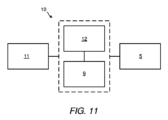
図11は、充電ケース1の充電システム10を示したブロック図である。充電システム10は、外部電源(例えば、商用電源、外部バッテリ、又は車両充電ポイント)に接続され、充電ケース1のバッテリ9を充電する(又は、例えば充電ケース1のバッテリ9が省略された場合に、エアロゾル送達システム20のバッテリ23を直接充電する)ように構成された電源コネクタ11を備える。充電システム10は、充電ケース1のバッテリ9と、エアロゾル送達システム20の第1のコネクタ26Aに接続されるポート5と、をさらに備える。充電システム10は、バッテリ9への電力の流れ及び/又はバッテリ9からの電力の流れを制御するためのコントローラ12をさらに備えていてもよい。
11 is a block diagram showing a charging
図12は、充電ケース1の第2の実施形態の(第1の実施形態の図5と同じ断面に沿う)断面図である。第2の実施形態の充電ケース1は、図1~図11の第1の実施形態の充電ケース1に類似しており、同様の特徴を有するが、相違点として、第2の実施形態の充電ケース1は、湾曲プロファイルを有するエアロゾル送達システム(図示せず)を収容するように構成された湾曲格納エリア4を有する。したがって、構造6が突き出る表面8は、大略湾曲状である。
Figure 12 is a cross-sectional view (along the same cross section as Figure 5 of the first embodiment) of a second embodiment of a charging
各構造6が突起6(例えば、リブ6)であり、断面が大略凸状である。本例において、各突起6の断面形状は、大略湾曲状である。これにより、突起6とエアロゾル送達システム20との間の接触面積が小さくなり、エアロゾル送達システム20と充電ケース1との間の熱伝達が抑えられるとともに、エアロゾル送達システム20と充電ケース1との間の摩擦が小さくなることで、ポート5に対するエアロゾル送達システム20の接続及び分離に要する力が小さくなる。図1~図11の第1の実施形態又は後述の図13及び図14の第3若しくは第4の実施形態は、湾曲面8並びに/又は凸状及び/若しくは湾曲状構造6を有するように改良可能であることが認識されるものとする。いくつかの実施形態において、格納エリア4は、U字状の断面を有する。
Each
ここで図13を参照して、この図は、充電ケース1の第3の実施形態を示している。第3の実施形態の充電ケース1は、図1~図11の第1の実施形態の充電ケース1に類似しており、同様の特徴を有する。相違点としては、第1の実施形態の各連続構造6が省略され、離隔した複数の構造6A、6B、6C、6Dで置き換えられている。
Now referring to FIG. 13, this shows a third embodiment of the charging
すなわち、第3の実施形態の充電ケース1は、第1行の構造6A、第2行の構造6B、第3行の構造6C、及び第4行の構造6Dを備える。隣り合う行の構造6A、6B、6C、6D間には、空間7Aが設けられ、充電ケース1とエアロゾル送達システム20との間の空隙7の一部を構成している。
That is, the charging
図1~図12の第1及び第2の実施形態と比較した図13の第3の実施形態の欠点として、構造6A、6B、6C、6Dが格納エリア4の第1及び第2の端部4A、4B間で不連続に延びているため、特定の構成においては、離隔した構造6A、6B、6C、6Dの縁部又は角にエアロゾル送達システム20が引っ掛かったり詰まったりする可能性が高くなる。
A disadvantage of the third embodiment of FIG. 13 compared to the first and second embodiments of FIGS. 1-12 is that because the
一方、隣り合う構造6A、6B、6C、6D間の空間7Aによって、充電ケース1とエアロゾル送達デバイス20との間の空隙7のサイズが大きくなるため、エアロゾル送達デバイス20の冷却が促進され、充電ケース1とエアロゾル送達デバイス20との間の熱伝達が抑えられる。
On the other hand, the
本例において、構造6A、6B、6C、6Dは、複数列の構造6A、6B、6C、6Dを構成するように位置合わせされている。本例において、充電ケース1は、3列の構造6A、6B、6C、6Dを備え、各列に4つの構造6A、6B、6C、6Dが含まれる。本例において、充電ケースは、4行の構造6A、6B、6C、6Dを備え、各行に3つの構造6A、6B、6C、6Dが設けられている。ただし、他の実施形態において、充電ケース1は、各行及び/又は列の構造の数が異なっていてもよいことが認識されるものとする。また、充電ケース1は、構造の行及び/又は列の数が異なっていてもよい。
In this example, the
本例において、構造6A、6B、6C、6Dは、規則的な行及び列に設けられている。これによって、充電ケース1とエアロゾル送達システム20との間のより均一な熱的空隙7が可能となる。ただし、他の実施形態(図示せず)においては、構造が不規則な行及び/又は不規則な列に設けられていてもよい。
In this example, the
本例においては、構造6A、6B、6C、6Dがすべて同じ形状である。ただし、他の実施形態においては、構造6A、6B、6C、6Dの一部が異なる形状を有していてもよい。
In this example,
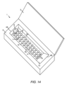
上記実施形態それぞれにおいて、構造6、6A、6B、6C、6Dは、長手方向リブ6、6A、6B、6C、6Dである。ただし、これらの構造は、その他任意の形状を有していてもよいことが認識されるものとする。例えば、上記構造は、図14に示すように円形であってもよく、これは、充電ケース1の第4の実施形態を示す。第4の実施形態において、構造6は、大略円形であり、隣り合う構造6間に空間7Aが形成されるように離隔している。構造6は、本体2及び/又は蓋(図14には示さず)の表面8から突き出た突起6である。これらの構造6は、頂部が大略平坦であってもよいし、又はそれぞれが大略凸状の断面を有していてもよく、上記構造6又は各構造6の断面形状が大略湾曲状であってもよい。これにより、エアロゾル送達システム20と充電ケース1との間の接触面積が抑えられる。上記構造6又は各構造6がドーム状であってもよい。
In each of the above embodiments, the
図1~図14に関して上述した第1、第2、第3、及び第4の実施形態の変形例においては、構造6が異なる形状(例えば、長円形、正方形、三角形、多角形、五角形、又は六角形)であってもよいことが認識されるものとする。
In variations of the first, second, third, and fourth embodiments described above with respect to Figures 1-14, it will be appreciated that the
図1~図14に関して上述した第1、第2、第3、及び第4の実施形態それぞれにおいて、構造6、6A、6B、6C、6Dは、突起である。例えば、突起は、本体2及び/又は蓋3の表面8から外方に突き出ていてもよい。ただし、代替的な一実施形態(図示せず)においては、これらの構造が窪みであってもよい。例えば、これらの構造は、本体2及び/又は蓋3の表面8から内方に突き出ていてもよい。充電ケース1は、1つ若しくは複数のこのような窪み及び/又は1つ若しくは複数の突起を備えていてもよい。上記又は各窪みは、エアロゾル送達システム20と充電ケース1との間の空隙を構成するため、エアロゾル送達システム20の冷却を改善するとともに、エアロゾル送達システム20と充電ケース1との間の熱伝達を抑える。また、上記又は各窪みは、充電ケース1とエアロゾル送達システム20との間の接触面積を小さくすることにより、ポート5とのエアロゾル送達システム20の接続及び分離において、両者間の摩擦を小さくする。いくつかの実施形態(図示せず)においては、窪みが1つ又は複数の凹みの形態である。
In the first, second, third and fourth embodiments described above with respect to Figs. 1-14, respectively, the
上記実施形態それぞれにおいて、突起6、6A、6B、6C、6Dは、エアロゾル送達システム20が最初に摺動してポート5から分離されてから充電ケース1の斜面12に接触するまで常に、少なくとも1つの突起がエアロゾル送達システム20と接触するように配置されている。これは、エアロゾル送達システム20を絶えず支持するとともに、エアロゾル送達システム20の摺動運動を滑らかにするのに役立つ。
In each of the above embodiments, the
本明細書に記載の種々実施形態は、特許請求の範囲に係る特徴の理解及び教示の補助としてのみ提示している。これらの実施形態は、実施形態の代表的なサンプルとして与えており、網羅的及び/又は排他的なものではない。本明細書に記載の利点、実施形態、例、機能、特徴、構造、及び/又は他の態様は、特許請求の範囲により規定される本発明の範囲に対する制限とも、特許請求の範囲の同等物に対する制限とも考えるべきではなく、また、特許請求の範囲に係る発明の範囲から逸脱することなく、他の実施形態の利用及び改良が可能であることが了解されるものとする。本発明の種々実施形態は、本明細書において具体的に記載した以外の開示の要素、構成要素、特徴、部分、ステップ、手段等の適当な組み合わせを好適に含んでいてもよいし、適当な組み合わせから成っていてもよいし、又は適当な組み合わせから本質的に成っていてもよい。また、本開示は、現時点では請求されていないものの、将来的に請求され得る他の発明を含んでいてもよい。
[発明の項目]
[項目1]
エアロゾル送達システム用の充電ケースであって、前記エアロゾル供給システムの少なくとも一部を前記充電ケースから離隔させて空隙を与えるように構成された1つ又は複数の構造を備える、充電ケース。
[項目2]
前記1つ又は複数の構造が、突起である、項目1に記載の充電ケース。
[項目3]
前記1つ又は複数の構造が、前記充電ケースの表面から突き出ている、項目2に記載の充電ケース。
[項目4]
前記構造又は各構造が、リブを備え、好ましくは、前記又は各リブが、直線又は実質的に直線である、項目2又は3に記載の充電ケース。
[項目5]
前記充電ケースが、前記エアロゾル送達システムが充電のため前記充電ケースに配置された場合に、前記エアロゾル送達システムの基礎となるように構成された表面を有し、前記構造又は各構造が、前記表面の表面積の20%未満、好ましくは15%未満、10%未満、又は5%未満にわたって設けられ、好ましくは、前記表面が、平面状の表面である、項目1~4のいずれか一項に記載の充電ケース。
[項目6]
前記エアロゾル送達システムが充電のため前記充電ケースに配置された場合に、前記エアロゾル送達システムとの前記又は全構造の総接触表面積が、最大400平方ミリメートル、好ましくは、最大300、250、200、150、125、又は100平方ミリメートルである、項目1~5のいずれか一項に記載の充電ケース。
[項目7]
前記構造又は各構造が、長手方向に延びている、項目1~6のいずれか一項に記載の充電ケース。
[項目8]
前記構造又は各構造が、少なくとも40mm、好ましくは、少なくとも60mm、80mm、100mm、又は120mmの範囲の長さを有する、項目1~7のいずれか一項に記載の充電ケース。
[項目9]
前記構造又は各構造が、0.1~1mmの範囲、好ましくは、0.1~0.5mmの範囲、好ましくは0.2~0.3mmの範囲の高さを有する、項目1~8のいずれか一項に記載の充電ケース。
[項目10]
前記構造又は各構造が、0.5~2mmの範囲、好ましくは、0.5~0.8mmの範囲、好ましくは0.6~0.7mmの範囲の幅を有する、項目1~9のいずれか一項に記載の充電ケース。
[項目11]
前記空隙を与える複数の構造を備える、項目1~10のいずれか一項に記載の充電ケース。
[項目12]
2~10個の範囲の構造、好ましくは、3~5個の範囲の構造を備える、項目11に記載の充電ケース。
[項目13]
前記構造が、互いに実質的に平行に延びている、項目11又は12に記載の充電ケース。
[項目14]
前記構造が、離散的で、互いに離隔している、項目11~13のいずれか一項に記載の充電ケース。
[項目15]
前記構造又は各構造が、大略凸状の断面を有し、好ましくは、前記構造又は各構造の断面形状が、大略湾曲状である、項目1~14のいずれか一項に記載の充電ケース。
[項目16]
前記エアロゾル送達システムを受容するように構成された格納エリアを備え、好ましくは、前記格納エリアが、キャビティである、項目1~15のいずれか一項に記載の充電ケース。
[項目17]
少なくとも1つの構造が、前記格納エリアに設けられている、項目16に記載の充電ケース。
[項目18]
前記エアロゾル送達システムに接続されるように構成されたポートを備え、好ましくは、前記ポートが、使用時に、前記エアロゾル送達システムが前記ポートから離れる方向に摺動して前記ポートから分離されるように構成されている、項目1~17のいずれか一項に記載の充電ケース。
[項目19]
少なくとも1つの構造が、前記ポートの近くに設けられている、項目18に記載の充電ケース。
[項目20]
少なくとも1つの構造が、前記エアロゾル送達システムが前記ポートに接続された場合に、前記構造が前記エアロゾル送達システムと接触するように配置されている、項目18又は19に記載の充電ケース。
[項目21]
前記ポートが、前記格納エリアの端部に設けられている、項目16又は17に従属する場合の、項目18~20のいずれか一項に記載の充電ケース。
[項目22]
斜面であり、前記構成要素が前記ポートから離れる方向に移動した場合に、前記エアロゾル供給システムの一部が前記斜面に沿って移動するように配置されている、斜面を備える、項目18~21のいずれか一項に記載の充電ケース。
[項目23]
前記構造又は各構造が、前記エアロゾル送達システムが前記ポートから分離されてから前記斜面に接触するまで常に、少なくとも1つの構造が前記エアロゾル送達システムと接触するように配置されている、項目18~21のいずれか一項に従属する場合の、項目22に記載の充電ケース。
[項目24]
前記充電ケースが、本体及び蓋を備え、前記本体及び/又は蓋が、前記1つ又は複数の構造を備える、項目1~23のいずれか一項に記載の充電ケース。
[項目25]
前記エアロゾル送達システムが、エアロゾル送達デバイスである、項目1~24のいずれか一項に記載の充電ケース。
[項目26]
前記エアロゾル送達システムをさらに備える、項目1~25のいずれか一項に記載の充電ケース。
[項目27]
前記エアロゾル送達システムが、エアロゾル化可能材料を含む取り外し可能な物品を受容するように構成されている、項目1~26のいずれか一項に記載の充電ケース。
[項目28]
前記エアロゾル化可能材料が、基板上に存在する、項目27に記載の充電ケース。
[項目29]
前記エアロゾル送達システムが、不燃性エアロゾル供給システムであり、好ましくは、タバコ加熱システムを備える、項目1~28のいずれか一項に記載の充電ケース。
[項目30]
項目1~29のいずれか一項に記載の充電ケースと、エアロゾル送達システムと、を備える部品キット。
[項目31]
前記エアロゾル送達システムにおいて使用する物品をさらに備え、好ましくは、前記物品が、エアロゾル生成材料を含む取り外し可能な物品である、項目30に記載の部品キット。
[項目32]
前記物品が、エアロゾル生成材料を含む取り外し可能な物品である、項目31に記載の部品キット。
The various embodiments described herein are presented only as aids in understanding and teaching the features of the claims. These embodiments are provided as a representative sample of embodiments and are not exhaustive and/or exclusive. The advantages, embodiments, examples, features, features, structures, and/or other aspects described herein should not be considered as limitations on the scope of the invention defined by the claims or limitations on the equivalents of the claims, and it is understood that other embodiments can be utilized and improved without departing from the scope of the claimed invention. The various embodiments of the present invention may suitably include, consist of, or essentially consist of any suitable combination of the disclosed elements, components, features, parts, steps, means, etc. other than those specifically described herein. The present disclosure may also include other inventions that are not currently claimed but may be claimed in the future.
[Items of the invention]
[Item 1]
A charging case for an aerosol delivery system, the charging case comprising one or more structures configured to space at least a portion of the aerosol delivery system from the charging case to provide an air gap.
[Item 2]
2. The charging case of
[Item 3]
3. The charging case of
[Item 4]
4. The charging case of
[Item 5]
5. The charging case of any one of
[Item 6]
6. The charging case of any one of
[Item 7]
7. The charging case of any one of
[Item 8]
8. The charging case of any one of the preceding claims, wherein the or each structure has a length of at least 40mm, preferably in the range of at least 60mm, 80mm, 100mm, or 120mm.
[Item 9]
9. The charging case according to any one of the preceding claims, wherein the or each structure has a height in the range of 0.1 to 1 mm, preferably in the range of 0.1 to 0.5 mm, preferably in the range of 0.2 to 0.3 mm.
[Item 10]
10. The charging case according to any one of the preceding claims, wherein the or each structure has a width in the range of 0.5 to 2 mm, preferably in the range of 0.5 to 0.8 mm, preferably in the range of 0.6 to 0.7 mm.
[Item 11]
11. The charging case according to any one of
[Item 12]
12. The charging case according to
[Item 13]
13. The charging case of
[Item 14]
14. The charging case of any one of
[Item 15]
15. The charging case of any one of
[Item 16]
16. The charging case of any one of
[Item 17]
17. The charging case of claim 16, wherein at least one structure is provided in the storage area.
[Item 18]
18. A charging case according to any one of
[Item 19]
20. The charging case of claim 18, wherein at least one structure is provided near the port.
[Item 20]
20. The charging case of claim 18 or 19, wherein at least one structure is positioned such that the structure contacts the aerosol delivery system when the aerosol delivery system is connected to the port.
[Item 21]
21. The charging case according to any one of items 18 to 20, when dependent on item 16 or 17, wherein the port is provided at an end of the storage area.
[Item 22]
22. The charging case of any one of items 18 to 21, comprising a sloped surface, the sloped surface being positioned such that when the component moves in a direction away from the port, a portion of the aerosol delivery system moves along the sloped surface.
[Item 23]
23. The charging case of
[Item 24]
24. The charging case of any one of
[Item 25]
25. The charging case of any one of
[Item 26]
26. The charging case of any one of
[Item 27]
27. The charging case of any one of
[Item 28]
28. The charging case of
[Item 29]
29. The charging case of any one of the preceding claims, wherein the aerosol delivery system is a non-combustible aerosol supply system, preferably comprising a tobacco heating system.
[Item 30]
30. A kit of parts comprising the charging case of any one of
[Item 31]
31. The kit of parts according to claim 30, further comprising an article for use in the aerosol delivery system, preferably the article being a removable article containing an aerosol-forming material.
[Item 32]
32. The kit of parts according to claim 31 , wherein the article is a removable article comprising an aerosol-forming material.
Claims (46)
前記充電ケースの表面から突き出ており、前記エアロゾル送達システムの少なくとも一部を前記充電ケースから離隔させて空隙を与えるとともに、前記エアロゾル送達システムと前記充電ケースとの間の摩擦を小さくするように構成された1つ又は複数の構造を備える、充電ケース。 1. A charging case for an aerosol delivery system, comprising:
A charging case comprising one or more structures protruding from a surface of the charging case and configured to separate at least a portion of the aerosol delivery system from the charging case to provide an air gap and to reduce friction between the aerosol delivery system and the charging case.
前記ポートが、前記格納エリアの端部に設けられている、請求項29に記載の充電ケース。 a storage area configured to receive the aerosol delivery system ;
30. The charging case of claim 29 , wherein the port is provided at an end of the storage area.
Applications Claiming Priority (3)
| Application Number | Priority Date | Filing Date | Title |
|---|---|---|---|
| GB2107602.1 | 2021-05-27 | ||
| GBGB2107602.1A GB202107602D0 (en) | 2021-05-27 | 2021-05-27 | A charging case |
| PCT/GB2022/051326 WO2022248856A1 (en) | 2021-05-27 | 2022-05-25 | A charging case |
Publications (2)
| Publication Number | Publication Date |
|---|---|
| JP2024520277A JP2024520277A (en) | 2024-05-24 |
| JP7704892B2 true JP7704892B2 (en) | 2025-07-08 |
Family
ID=76741453
Family Applications (1)
| Application Number | Title | Priority Date | Filing Date |
|---|---|---|---|
| JP2023566577A Active JP7704892B2 (en) | 2021-05-27 | 2022-05-25 | Charging case |
Country Status (9)
| Country | Link |
|---|---|
| US (1) | US20240180261A1 (en) |
| EP (1) | EP4348799A1 (en) |
| JP (1) | JP7704892B2 (en) |
| KR (1) | KR20230170792A (en) |
| CN (1) | CN117837046A (en) |
| BR (1) | BR112023024794A2 (en) |
| CA (1) | CA3216538A1 (en) |
| GB (1) | GB202107602D0 (en) |
| WO (1) | WO2022248856A1 (en) |
Citations (4)
| Publication number | Priority date | Publication date | Assignee | Title |
|---|---|---|---|---|
| JP3105032U (en) | 2003-05-06 | 2004-10-21 | ジェクソン エレクトリック カンパニー リミテッド | Battery charger |
| JP2008277243A (en) | 2007-04-27 | 2008-11-13 | Samsung Sdi Co Ltd | Battery module |
| JP2008311130A (en) | 2007-06-15 | 2008-12-25 | Hitachi Vehicle Energy Ltd | Power supply device and cooling method thereof |
| US20190230985A1 (en) | 2018-01-26 | 2019-08-01 | Juul Labs, Inc. | Charging case assembly |
Family Cites Families (22)
| Publication number | Priority date | Publication date | Assignee | Title |
|---|---|---|---|---|
| US3745048A (en) * | 1970-12-30 | 1973-07-10 | Gen Electric | Battery cooling system |
| JPH08130039A (en) * | 1994-10-31 | 1996-05-21 | Sanyo Electric Co Ltd | Charger |
| US5918186A (en) * | 1996-10-15 | 1999-06-29 | Ericsson Inc. | Rechargeable battery enabling reduction of battery overheating probability during charging |
| KR100627335B1 (en) * | 2004-06-25 | 2006-09-25 | 삼성에스디아이 주식회사 | Battery Modules and Battery Modules |
| KR20060102853A (en) * | 2005-03-25 | 2006-09-28 | 삼성에스디아이 주식회사 | Secondary battery module |
| US7257429B2 (en) * | 2005-05-13 | 2007-08-14 | Symbol Technologies, Inc. | Overheating and spill resistant mobile device docking cradle |
| US9373974B2 (en) * | 2012-09-20 | 2016-06-21 | GM Global Technology Operations LLC | Apparatus for inductive charging of portable devices in vehicles |
| US9814330B2 (en) * | 2012-12-21 | 2017-11-14 | Pizza On “Da” Go, LLC | Pizza slice container |
| ES2799434T3 (en) * | 2013-06-04 | 2020-12-17 | Nicoventures Holdings Ltd | Container |
| GB2518598B (en) * | 2013-08-30 | 2016-06-01 | Nicoventures Holdings Ltd | Apparatus with battery power control |
| US10855092B2 (en) * | 2014-01-29 | 2020-12-01 | Steven Stanimirovic | Combination electronic cigarette holder and charger |
| US10167134B2 (en) * | 2015-10-13 | 2019-01-01 | Altria Client Services Llc | Article carrier for an electronic vaping device |
| USD889739S1 (en) * | 2018-07-12 | 2020-07-07 | Juul Labs, Inc. | Case |
| EP3758184A1 (en) * | 2019-06-28 | 2020-12-30 | Nerudia Limited | Charging device and smoking substitute kit |
| US20210041170A1 (en) * | 2019-08-07 | 2021-02-11 | Ear Technology Corporation | Dryer and sanitizer for rechargeable electronic devices |
| GB202019673D0 (en) * | 2020-12-14 | 2021-01-27 | Nicoventures Trading Ltd | Case |
| US11910561B2 (en) * | 2021-01-27 | 2024-02-20 | Polaris Industries Inc. | Cooled wireless mobile device charger |
| CN113142686B (en) * | 2021-04-22 | 2023-07-25 | 立讯精密工业股份有限公司 | Charging box |
| GB202107603D0 (en) * | 2021-05-27 | 2021-07-14 | Nicoventures Trading Ltd | A charging case |
| CN113726027B (en) * | 2021-09-03 | 2025-02-14 | 台达电子企业管理(上海)有限公司 | Wireless charging device |
| TWI856401B (en) * | 2022-08-01 | 2024-09-21 | 英業達股份有限公司 | Wireless charging device |
| DE102024101409A1 (en) * | 2024-01-18 | 2025-07-24 | Bury Sp. Z.O.O. | Charging device for wirelessly charging an electrical energy storage device and method for controlling a charging device |
-
2021
- 2021-05-27 GB GBGB2107602.1A patent/GB202107602D0/en not_active Ceased
-
2022
- 2022-05-25 CN CN202280038221.0A patent/CN117837046A/en active Pending
- 2022-05-25 BR BR112023024794A patent/BR112023024794A2/en not_active Application Discontinuation
- 2022-05-25 CA CA3216538A patent/CA3216538A1/en active Pending
- 2022-05-25 EP EP22731757.5A patent/EP4348799A1/en active Pending
- 2022-05-25 WO PCT/GB2022/051326 patent/WO2022248856A1/en not_active Ceased
- 2022-05-25 KR KR1020237040363A patent/KR20230170792A/en not_active Withdrawn
- 2022-05-25 US US18/564,165 patent/US20240180261A1/en active Pending
- 2022-05-25 JP JP2023566577A patent/JP7704892B2/en active Active
Patent Citations (4)
| Publication number | Priority date | Publication date | Assignee | Title |
|---|---|---|---|---|
| JP3105032U (en) | 2003-05-06 | 2004-10-21 | ジェクソン エレクトリック カンパニー リミテッド | Battery charger |
| JP2008277243A (en) | 2007-04-27 | 2008-11-13 | Samsung Sdi Co Ltd | Battery module |
| JP2008311130A (en) | 2007-06-15 | 2008-12-25 | Hitachi Vehicle Energy Ltd | Power supply device and cooling method thereof |
| US20190230985A1 (en) | 2018-01-26 | 2019-08-01 | Juul Labs, Inc. | Charging case assembly |
Also Published As
| Publication number | Publication date |
|---|---|
| EP4348799A1 (en) | 2024-04-10 |
| CN117837046A (en) | 2024-04-05 |
| CA3216538A1 (en) | 2022-12-01 |
| KR20230170792A (en) | 2023-12-19 |
| US20240180261A1 (en) | 2024-06-06 |
| BR112023024794A2 (en) | 2024-02-15 |
| JP2024520277A (en) | 2024-05-24 |
| WO2022248856A1 (en) | 2022-12-01 |
| GB202107602D0 (en) | 2021-07-14 |
Similar Documents
| Publication | Publication Date | Title |
|---|---|---|
| JP7764549B2 (en) | Aerosol delivery device having a segmented electric heater | |
| JP2023075167A (en) | smoking goods | |
| EP2892371B1 (en) | Single-use connector and cartridge for a smoking article and related method | |
| JP2024519701A (en) | Charging case | |
| JP7704892B2 (en) | Charging case | |
| JP2025529147A (en) | Aerosol delivery device with alternative consumable loading and dispensing configurations | |
| RU2821228C2 (en) | Aerosol delivery device with segmented electric heater (options) | |
| JP2025535250A (en) | Aerosol-Generating Assembly | |
| RU2775373C2 (en) | Smoking products (options) | |
| KR20250172972A (en) | Consumables set for aerosol generator | |
| KR20250159023A (en) | Aerosol generating device including a heat shield and associated aerosol generating assembly | |
| JP2026507698A (en) | Aerosol generating device including a grip portion and related aerosol generating assembly |
Legal Events
| Date | Code | Title | Description |
|---|---|---|---|
| A621 | Written request for application examination |
Free format text: JAPANESE INTERMEDIATE CODE: A621 Effective date: 20231227 |
|
| A521 | Request for written amendment filed |
Free format text: JAPANESE INTERMEDIATE CODE: A523 Effective date: 20240321 |
|
| A977 | Report on retrieval |
Free format text: JAPANESE INTERMEDIATE CODE: A971007 Effective date: 20241120 |
|
| A131 | Notification of reasons for refusal |
Free format text: JAPANESE INTERMEDIATE CODE: A131 Effective date: 20241210 |
|
| A601 | Written request for extension of time |
Free format text: JAPANESE INTERMEDIATE CODE: A601 Effective date: 20250306 |
|
| A521 | Request for written amendment filed |
Free format text: JAPANESE INTERMEDIATE CODE: A523 Effective date: 20250509 |
|
| TRDD | Decision of grant or rejection written | ||
| A01 | Written decision to grant a patent or to grant a registration (utility model) |
Free format text: JAPANESE INTERMEDIATE CODE: A01 Effective date: 20250603 |
|
| A61 | First payment of annual fees (during grant procedure) |
Free format text: JAPANESE INTERMEDIATE CODE: A61 Effective date: 20250626 |
|
| R150 | Certificate of patent or registration of utility model |
Ref document number: 7704892 Country of ref document: JP Free format text: JAPANESE INTERMEDIATE CODE: R150 |