JP7702869B2 - Excavators and systems for excavators - Google Patents
Excavators and systems for excavators Download PDFInfo
- Publication number
- JP7702869B2 JP7702869B2 JP2021537298A JP2021537298A JP7702869B2 JP 7702869 B2 JP7702869 B2 JP 7702869B2 JP 2021537298 A JP2021537298 A JP 2021537298A JP 2021537298 A JP2021537298 A JP 2021537298A JP 7702869 B2 JP7702869 B2 JP 7702869B2
- Authority
- JP
- Japan
- Prior art keywords
- shovel
- authentication information
- management device
- mobile terminal
- engine
- Prior art date
- Legal status (The legal status is an assumption and is not a legal conclusion. Google has not performed a legal analysis and makes no representation as to the accuracy of the status listed.)
- Active
Links
Images


Classifications
-
- B—PERFORMING OPERATIONS; TRANSPORTING
- B60—VEHICLES IN GENERAL
- B60R—VEHICLES, VEHICLE FITTINGS, OR VEHICLE PARTS, NOT OTHERWISE PROVIDED FOR
- B60R25/00—Fittings or systems for preventing or indicating unauthorised use or theft of vehicles
- B60R25/20—Means to switch the anti-theft system on or off
- B60R25/24—Means to switch the anti-theft system on or off using electronic identifiers containing a code not memorised by the user
-
- E—FIXED CONSTRUCTIONS
- E02—HYDRAULIC ENGINEERING; FOUNDATIONS; SOIL SHIFTING
- E02F—DREDGING; SOIL-SHIFTING
- E02F9/00—Component parts of dredgers or soil-shifting machines, not restricted to one of the kinds covered by groups E02F3/00 - E02F7/00
-
- G—PHYSICS
- G06—COMPUTING OR CALCULATING; COUNTING
- G06F—ELECTRIC DIGITAL DATA PROCESSING
- G06F21/00—Security arrangements for protecting computers, components thereof, programs or data against unauthorised activity
- G06F21/30—Authentication, i.e. establishing the identity or authorisation of security principals
- G06F21/31—User authentication
Landscapes
- Engineering & Computer Science (AREA)
- Computer Security & Cryptography (AREA)
- Theoretical Computer Science (AREA)
- General Engineering & Computer Science (AREA)
- Computer Hardware Design (AREA)
- Structural Engineering (AREA)
- Civil Engineering (AREA)
- Software Systems (AREA)
- Physics & Mathematics (AREA)
- General Physics & Mathematics (AREA)
- Mining & Mineral Resources (AREA)
- Mechanical Engineering (AREA)
- Component Parts Of Construction Machinery (AREA)
- Operation Control Of Excavators (AREA)
Description
本開示は、ショベル及びショベル用システムに関する。 The present disclosure relates to an excavator and a system for an excavator.
従来、操作者が持っている携帯端末との間で通信を行い、携帯端末から送信される認証情報とショベルに記憶されている認証情報とを照合し、両者が一致した場合、ショベルの動作を許可するように構成されたショベルが知られている(特許文献1参照。)。Conventionally, there is known a shovel that is configured to communicate with a mobile terminal carried by an operator, compare authentication information sent from the mobile terminal with authentication information stored in the shovel, and permit operation of the shovel if the two match (see Patent Document 1).
しかしながら、上述のショベルを動作させようとする操作者は、携帯端末とショベルとを物理的に接続するという煩雑な作業を行う必要がある。However, an operator who wants to operate the above-mentioned shovel must go through the cumbersome task of physically connecting the mobile terminal to the shovel.
そこで、より簡単な構成でショベルの駆動源であるエンジンの不正な始動を防止できるようにすることが望ましい。 Therefore, it is desirable to be able to prevent unauthorized starting of the engine, which is the power source of the shovel, with a simpler configuration.
本発明の実施形態に係るショベルは、外部の管理装置と通信接続されるショベルであって、駆動源を備え、前記管理装置が発行した認証情報と、携帯端末によって受信されるとともに前記ショベルに搭載されている装置を通じて入力された認証情報とが照合できたときに前記駆動源の始動を許可するように構成され、前記ショベルに搭載されている装置は、メカニカルキーによって施錠可能なドアを有する運転室の内部に設置されており、前記メカニカルキーにより、電力が供給される状態と電力が供給されない状態とが切り換えられる。
A shovel according to an embodiment of the present invention is a shovel that is communicatively connected to an external management device, is equipped with a drive source, and is configured to permit starting of the drive source when authentication information issued by the management device is matched with authentication information received by a mobile terminal and input through a device mounted on the shovel, the device mounted on the shovel is installed inside a driver's cab having a door that can be locked by a mechanical key, and the mechanical key switches between a state in which power is supplied and a state in which power is not supplied .
上述のショベルは、より簡単な構成でエンジンの不正な始動を防止できる。 The above-mentioned shovel has a simpler configuration that prevents unauthorized engine start.
以下、図面を参照して発明を実施するための形態について説明する。各図面において、同一構成部分には同一符号を付し、重複した説明を省略する場合がある。 Below, a description of the embodiment of the invention will be given with reference to the drawings. In each drawing, the same components are given the same reference numerals, and duplicate explanations may be omitted.
図1は、本発明の実施形態に係るショベルの一例を示す側面図である。ショベルPSの下部走行体1には、旋回機構2を介して旋回可能に上部旋回体3が搭載されている。上部旋回体3には、ブーム4が取り付けられている。ブーム4の先端には、アーム5が取り付けられている。アーム5の先端には、バケット6が取り付けられている。
Figure 1 is a side view showing an example of an excavator according to an embodiment of the present invention. An upper rotating body 3 is mounted on a lower running
ブーム4、アーム5、及びバケット6は、アタッチメントの一例としての掘削アタッチメントを構成している。ブーム4は、ブームシリンダ7によって駆動され、アーム5は、アームシリンダ8によって駆動され、バケット6は、バケットシリンダ9によって駆動される。また、ブーム4にはブーム角度センサS1が取り付けられ、アーム5にはアーム角度センサS2が取り付けられ、バケット6にはバケット角度センサS3が取り付けられている。The boom 4,
ブーム角度センサS1はブーム4の回動角度を検出する。本実施形態では、ブーム角度センサS1は加速度センサであり、上部旋回体3に対するブーム4の回動角度(以下、「ブーム角度」とする。)を検出できる。ブーム角度は、例えば、ブーム4を最も下げたときに最小角度となり、ブーム4を上げるにつれて大きくなる。The boom angle sensor S1 detects the rotation angle of the boom 4. In this embodiment, the boom angle sensor S1 is an acceleration sensor and can detect the rotation angle of the boom 4 relative to the upper rotating body 3 (hereinafter referred to as the "boom angle"). For example, the boom angle is at its minimum when the boom 4 is lowered to the lowest and increases as the boom 4 is raised.
アーム角度センサS2はアーム5の回動角度を検出する。本実施形態では、アーム角度センサS2は加速度センサであり、ブーム4に対するアーム5の回動角度(以下、「アーム角度」とする。)を検出できる。アーム角度は、例えば、アーム5を最も閉じたときに最小角度となり、アーム5を開くにつれて大きくなる。The arm angle sensor S2 detects the rotation angle of the
バケット角度センサS3はバケット6の回動角度を検出する。本実施形態では、バケット角度センサS3は加速度センサであり、アーム5に対するバケット6の回動角度(以下、「バケット角度」とする。)を検出できる。バケット角度は、例えば、バケット6を最も閉じたときに最小角度となり、バケット6を開くにつれて大きくなる。The bucket angle sensor S3 detects the rotation angle of the
ブーム角度センサS1、アーム角度センサS2、及びバケット角度センサS3はそれぞれ、可変抵抗器を利用したポテンショメータ、対応する油圧シリンダのストローク量を検出するストロークセンサ、連結ピン回りの回動角度を検出するロータリエンコーダ、ジャイロセンサ、又は、加速度センサとジャイロセンサの組み合わせ等であってもよい。The boom angle sensor S1, arm angle sensor S2, and bucket angle sensor S3 may each be a potentiometer using a variable resistor, a stroke sensor that detects the stroke amount of the corresponding hydraulic cylinder, a rotary encoder that detects the rotation angle around the connecting pin, a gyro sensor, or a combination of an acceleration sensor and a gyro sensor, etc.
上部旋回体3には、エンジン11、機体傾斜センサS4、及び旋回角速度センサS5が搭載されている。そして、上部旋回体3には、撮像装置80が設けられている。撮像装置80は、前カメラ80F、左カメラ80L、後カメラ80B、右カメラ80R、及び室内カメラ80Pを含む。The upper rotating body 3 is equipped with an
室内カメラ80Pは、キャビン10内に設置されるカメラである。本実施形態では、室内カメラ80Pは、図3に示すように、キャビン10内に設置された表示装置40の上部に取り付けられている。The
機体傾斜センサS4は、例えば、所定の平面に対する上部旋回体3の傾斜を検出するように構成されている。本実施形態では、機体傾斜センサS4は、水平面に対する上部旋回体3の前後軸回りの傾斜角及び左右軸回りの傾斜角を検出する加速度センサである。上部旋回体3の前後軸及び左右軸は、例えば、ショベルPSの旋回軸上の一点であるショベル中心点で互いに直交する。The machine body inclination sensor S4 is configured to detect, for example, the inclination of the upper rotating body 3 relative to a predetermined plane. In this embodiment, the machine body inclination sensor S4 is an acceleration sensor that detects the inclination angle about the fore-aft axis and the lateral axis of the upper rotating body 3 relative to a horizontal plane. The fore-aft axis and the lateral axis of the upper rotating body 3 are perpendicular to each other, for example, at the shovel center point, which is a point on the rotation axis of the shovel PS.
旋回角速度センサS5は、上部旋回体3の旋回角速度を検出するように構成されている。旋回角速度センサS5は、上部旋回体3の旋回角度を検出するように構成されていてもよい。本実施形態では、旋回角速度センサS5は、ジャイロセンサである。旋回角速度センサS5は、レゾルバ又はロータリエンコーダ等であってもよい。The rotation angular velocity sensor S5 is configured to detect the rotation angular velocity of the upper rotating body 3. The rotation angular velocity sensor S5 may be configured to detect the rotation angle of the upper rotating body 3. In this embodiment, the rotation angular velocity sensor S5 is a gyro sensor. The rotation angular velocity sensor S5 may be a resolver, a rotary encoder, or the like.
上部旋回体3には、運転室としてのキャビン10が設けられている。キャビン10の頂部には、通信装置T1及びGNSS受信機T2が設けられている。通信装置T1は、ショベルPSの外部に設置された管理装置90等と通信装置T1との間の通信を制御する。GNSS受信機T2は、ショベルPSの位置(緯度、経度、及び高度)を検出する。キャビン10内には、コントローラ30、表示装置40、音出力装置43、入力装置45、及び記憶装置47等が設けられている。The upper rotating body 3 is provided with a
コントローラ30は、ショベルPSの駆動制御を行う主制御部として機能する。コントローラ30は、CPU及び内部メモリを含む演算処理装置で構成されている。コントローラ30の各種機能は、CPUが内部メモリに格納されているプログラムを実行することで実現される。The
表示装置40は、各種情報を表示するように構成されている。本実施形態では、表示装置40は、液晶ディスプレイである。表示装置40は、CAN又はLIN等の通信ネットワークを介してコントローラ30に接続される。表示装置40は、専用線を介してコントローラ30に接続されてもよい。The
音出力装置43は、コントローラ30からの出力指令に応じて各種の音情報を出力するように構成されている。本実施形態では、音出力装置43はスピーカである。音出力装置43は、ブザー等の警報器であってもよい。The sound output device 43 is configured to output various types of sound information in response to an output command from the
入力装置45は、ショベルPSの操作者がコントローラ30に各種情報を入力するための装置である。本実施形態では、入力装置45は、表示装置40の表面に設けられるメンブレンスイッチである。入力装置45は、タッチパネル等であってもよい。The input device 45 is a device that allows the operator of the excavator PS to input various information to the
記憶装置47は、各種情報を記憶するための装置である。記憶装置47は、例えば、半導体メモリ等の不揮発性記憶媒体である。本実施形態では、記憶装置47は、コントローラ30等が出力する各種情報を記憶する。The
キャビン10の左側面にはドアDRが設置され、上部旋回体3の左側面にはサイドカバーCVが設定されている。ドアDR及びサイドカバーCVは、共通のメカニカルキーで施錠・解錠できるように構成されている。
A door DR is installed on the left side of the
次に、図2を参照し、ショベルPSの駆動系の構成例について説明する。図2は、ショベルPSの駆動系の構成例を示す図である。Next, an example of the configuration of the drive system of the shovel PS will be described with reference to Figure 2. Figure 2 is a diagram showing an example of the configuration of the drive system of the shovel PS.
ショベルPSの駆動系は、主に、エンジン11、メインポンプ14、パイロットポンプ15、コントロールバルブ17、操作装置26、コントローラ30、蓄電池70、電装品72、キーシリンダ73、エンジン制御装置74、及びエンジン回転数調整ダイヤル75等を含む。
The drive system of the excavator PS mainly includes an
エンジン11は、ショベルPSの駆動源であり、例えば、所定の回転数を維持するように動作するディーゼルエンジンである。エンジン11の出力軸はメインポンプ14及びパイロットポンプ15のそれぞれの入力軸に接続される。The
メインポンプ14は、作動油ライン16を介して作動油をコントロールバルブ17に供給する油圧ポンプである。本実施形態では、メインポンプ14は、斜板式可変容量型油圧ポンプである。The
パイロットポンプ15は、パイロットライン25を介して操作装置26等の油圧制御機器に作動油を供給するための油圧ポンプである。本実施形態では、パイロットポンプ15は、固定容量型油圧ポンプである。The
コントロールバルブ17は、ショベルPSにおける油圧システムを制御する油圧制御バルブである。コントロールバルブ17は、例えば、ブームシリンダ7、アームシリンダ8、バケットシリンダ9、右走行用油圧モータ1A、左走行用油圧モータ1B、及び旋回用油圧モータ2Aのうちの一又は複数のものに対し、メインポンプ14から供給された作動油を選択的に供給する。なお、以下の説明では、ブームシリンダ7、アームシリンダ8、バケットシリンダ9、右走行用油圧モータ1A、左走行用油圧モータ1B、及び旋回用油圧モータ2Aをまとめて「油圧アクチュエータ」と称する。The
操作装置26は、操作者が油圧アクチュエータの操作のために用いる装置である。本実施形態では、操作装置26は、操作レバー及び操作ペダルを含む。操作装置26は、パイロットライン25を介して、パイロットポンプ15から供給された作動油を油圧アクチュエータのそれぞれに対応する制御弁のパイロットポートに供給できるように構成されている。なお、パイロットポートのそれぞれに供給される作動油の圧力であるパイロット圧は、油圧アクチュエータのそれぞれに対応する操作装置26の操作方向及び操作量に応じた圧力とされる。The operating
コントローラ30は、ショベルPSを制御するための制御装置である。本実施形態では、コントローラ30は、CPU、RAM、及びROM等を備えたコンピュータで構成されている。コントローラ30のCPUは、各種機能に対応するプログラムをROMから読み出してRAMにロードして実行することで、それらプログラムのそれぞれに対応する機能を実現する。The
蓄電池70は、スタータモータ11b、コントローラ30、表示装置40、通信装置T1、及び電装品72等(以下、「電装品72等」とする。)に電力を供給できるように構成されている。蓄電池70はエンジン11のオルタネータ11a(発電機)で発電した電力で充電される。The
キーシリンダ73は、エンジン11を始動させる際に操作者がメカニカルキーを差し込むことができるように構成されている。本実施形態では、メカニカルキーは、ドアDR及びサイドカバーCVの施錠・解錠に用いられるメカニカルキーである。The
操作者は、メカニカルキーをキーシリンダ73に差し込んでキーシリンダ73を回転させることで、キーシリンダ73の回転位置として、「OFF」、「ACC」、「ON」、及び「START」の4つの回転位置の何れかを選択できるように構成されている。「OFF」は、操作者がメカニカルキーを抜き差しする際に選択される回転位置である。「ACC」は、電装品等72に電力が供給される状態になる回転位置である。「ON」は、エンジン11を始動させた後でエンジン11の稼動を維持する際に選択される回転位置である。「START」は、エンジン11を始動させる際に選択される回転位置である。キーシリンダ73の回転位置として「START」が選択されると、スタータモータ11bは、蓄電池70からの電力で駆動されてエンジン11を始動させる。The operator can insert a mechanical key into the
エンジン11の始動は、不図示のエンジンボタンを用いて行われてもよい。この場合、キーシリンダ73は省略されてもよい。具体的には、エンジンボタンは、例えば、1回の押下で「ACC」が選択されたときと同じ状態を実現し、2回の押下で「START」が選択されたときと同じ状態を実現し、長押しされたときに「OFF」が選択されたときと同じ状態を実現するように構成されていてもよい。The
エンジン制御装置74は、エンジン11を制御する装置である。エンジン制御装置74は、例えば、コントローラ30からの指令に基づき、燃料噴射量等を調整してエンジン回転数を制御する。エンジン回転数は、例えば、エンジン回転数調整ダイヤル75により操作者が設定した目標エンジン回転数となるように制御される。The
エンジン回転数調整ダイヤル75は、目標エンジン回転数を設定するためのダイヤルである。本実施形態では、エンジン回転数調整ダイヤル75は、目標エンジン回転数を4段階で切り換えできるように構成されている。具体的には、エンジン回転数調整ダイヤル75は、SPモード、Hモード、Aモード、及びIDLEモードの4段階でエンジン回転数を切り換えできるように構成されている。図2は、エンジン回転数調整ダイヤル75でHモードが選択された状態を示す。エンジン回転数調整ダイヤル75は、目標エンジン回転数に関するデータをコントローラ30に対して出力する。The engine
SPモードは、作業量を優先したい場合に選択される作業モードであり、最も高い目標エンジン回転数を利用する。Hモードは、作業量と燃費を両立させたい場合に選択される作業モードであり、2番目に高い目標エンジン回転数を利用する。Aモードは、燃費を優先させながら低騒音でショベルPSを稼働させたい場合に選択される作業モードであり、3番目に高い目標エンジン回転数を利用する。IDLEモードは、エンジンをアイドリング状態にしたい場合に選択される作業モードであり、最も低い目標エンジン回転数を利用する。そして、エンジン11は、エンジン回転数調整ダイヤル75で選択された作業モードに対応する目標エンジン回転数となるように回転数制御される。
SP mode is a work mode selected when priority is given to workload, and uses the highest target engine speed. H mode is a work mode selected when priority is given to workload and fuel efficiency, and uses the second highest target engine speed. A mode is a work mode selected when priority is given to fuel efficiency while operating the excavator PS with low noise, and uses the third highest target engine speed. IDLE mode is a work mode selected when the engine is to be put into an idling state, and uses the lowest target engine speed. The
表示装置40は、画像表示部41上に表示する画像を生成する変換処理部40aを含む。変換処理部40aは、撮像装置80の出力に基づいて画像表示部41上に表示するカメラ画像を生成する。そのため、撮像装置80は、例えば専用線を介して表示装置40に接続される。また、変換処理部40aは、コントローラ30の出力に基づいて画像表示部41上に表示する画像を生成する。The
撮像装置80は、前カメラ80F、左カメラ80L、後カメラ80B、及び右カメラ80Rを含む。前カメラ80Fは、例えば、キャビン10の天井に取り付けられ、ショベルPSの前方を撮像する。左カメラ80Lは、例えば、上部旋回体3の左側に取り付けられ、ショベルPSの左方を撮像する。後カメラ80Bは、上部旋回体3の後側に取り付けられ、ショベルPSの後方を撮像する。右カメラ80Rは、上部旋回体3の右側に取り付けられ、ショベルPSの右方を撮像する。前カメラ80F、左カメラ80L、後カメラ80B、及び右カメラ80Rは、例えば、CCD又はCMOS等の撮像素子を有するデジタルカメラであり、撮影した画像をキャビン10内に設けられている表示装置40に送信する。The
なお、変換処理部40aは、表示装置40が有する機能としてではなく、コントローラ30が有する機能として実現されてもよい。この場合、撮像装置80は、表示装置40ではなく、コントローラ30に接続される。The
表示装置40は、入力部42としてのスイッチパネルを含む。スイッチパネルは、各種ハードウェアスイッチを含むパネルである。スイッチパネルは、例えば、ハードウェアボタンとしてのライトスイッチ42a、ワイパースイッチ42b、及びウインドウォッシャスイッチ42cを含む。ライトスイッチ42aは、キャビン10の外部に取り付けられるライトの点灯・消灯を切り換えるためのスイッチである。ワイパースイッチ42bは、ワイパーの作動・停止を切り換えるためのスイッチである。また、ウインドウォッシャスイッチ42cは、ウインドウォッシャ液を噴射するためのスイッチである。The
エンジン11は、エンジン制御装置74により制御される。エンジン制御装置74は、エンジン11の状態を示す各種のデータ(例えば、水温センサ11cで検出される冷却水温を示すデータ)をコントローラ30に対して出力する。The
レギュレータ13は、メインポンプ14の吐出量を制御するように構成されている。本実施形態では、レギュレータ13は、メインポンプ14の斜板傾転角を調整してメインポンプ14の吐出量を制御する。レギュレータ13は、斜板傾転角を示すデータをコントローラ30に対して出力する。The
油温センサ14cは、作動油が貯蔵されたタンクとメインポンプ14との間の管路を流れる作動油の温度を検出するように構成されている。油温センサ14cは、検出した油温に関する情報をコントローラ30に対して出力する。The
吐出圧センサ28は、メインポンプ14の吐出圧を検出するように構成されている。吐出圧センサ28は、検出した吐出圧に関する情報を、コントローラ30に対して出力する。The
操作圧センサ29は、操作装置26が生成したパイロット圧を検出するように構成されている。操作圧センサ29は、検出したパイロット圧に関する情報を、コントローラ30に対して出力する。The operating
コントローラ30は、水温センサ11c、レギュレータ13、油温センサ14c、吐出圧センサ28、操作圧センサ29、及びエンジン回転数調整ダイヤル75等から受信したデータを一時記憶部30aに記憶しておき、必要なときに表示装置40に送信できる。The
ゲートロックレバー49は、ショベルPSが誤って操作されるのを防止する機構である。本実施形態では、ゲートロックレバー49は、キャビン10のドアと運転席との間に設けられている。コントローラ30は、ゲートロックレバー49が押し下げられている状態でゲートロック弁49a(図2参照。)を閉状態とし、ゲートロックレバー49が引き上げられている状態でゲートロック弁49aを開状態とするように構成されている。The
ゲートロック弁49aは、パイロットポンプ15と操作装置26(図2参照。)との間の油路に設けられている切換弁である。ゲートロック弁49aは、コントローラ30からの指令に応じて開閉するように構成されているが、ゲートロックレバー49と機械的に接続され、ゲートロックレバー49の動作に応じて開閉するように構成されていてもよい。The
ゲートロック弁49aは、閉状態において、パイロットポンプ15と操作装置26との間の作動油の流れを遮断して操作装置26を無効にする。また、ゲートロック弁49aは、開状態において、パイロットポンプ15と操作装置26との間を連通させて操作装置26を有効にする。すなわち、操作者が運転席に乗り込んでゲートロックレバー49を引き上げると、操作装置26は、油圧アクチュエータを動かすことができる状態(ロック解除状態)になる。操作者がゲートロックレバー49を押し下げると、操作装置26は、油圧アクチュエータを動かすことができない状態(ロック状態)になる。When the
通信装置T1は、通信ネットワーク93を介して管理装置90と相互に通信可能となるように構成されている。The communication device T1 is configured to be able to communicate with the
管理装置90は、例えば、ショベルPSの外部に設置されたコンピュータ等であり、専門スタッフ(設計者等)がショベルPSの状況を遠隔にいながら把握できるように構成されている。コントローラ30は、ショベルPSに取り付けられている各種装置の出力を一時記憶部30a等に蓄積し、必要に応じて管理装置90に送信できる。The
次に、図3を参照し、エンジン11を始動させる手順の一例について説明する。図3は、エンジン11を始動させる手順の一例を示す図である。図3の部分図F1は、ショベルPSの操作者が携帯している携帯端末200の画面を示し、部分図F2は、ショベルPSのキャビン10内の様子を示している。図3の例では、携帯端末200は、通信機能、表示機能、及び入力機能等を備えたスマートフォンである。携帯端末200は、タブレットPC、ノートPC、スマートウォッチ、又は携帯電話等であってもよい。図3におけるショベルPS、管理装置90、及び携帯端末200は、ショベル用システムの一例である、ショベルPSの盗難を防止する盗難防止システムを構成している。Next, referring to FIG. 3, an example of a procedure for starting the
最初に、ショベルPSの操作者は、メカニカルキーを利用してキャビン10のドアDRを解錠し、ドアDRを開けてキャビン10内に乗り込む。そして、操作者は、キーシリンダ73にメカニカルキーを差し込んでキーシリンダ73の回転位置を「ACC」に合わせ、室内カメラ80P及び通信装置T1を起動させる。First, the operator of the excavator PS uses the mechanical key to unlock the door DR of the
その後、ショベルPSの操作者は、携帯端末200を操作し、矢印AR1で示すように、携帯端末200から管理装置90に要求信号を送信させる。要求信号は、認証情報の発行を管理装置90に要求する信号である。認証情報は、ショベルPSのエンジン11を始動させようとしている操作者が正規の操作者であることを認証する際に利用される情報であり、例えば、パスワード又はパスコード等である。本実施形態では、認証情報は、所定の期間に限り有効なパスワードである。所定の期間は、例えば、発行から1時間、発行日の午前9時から午後5時迄、又は、所定の開始日時から所定の終了日時迄等である。認証情報は、1回又は所定回数の始動に限り有効なパスワードであってもよい。認証情報は、例えば、発行毎に異なるように、発行日時及び要求信号が発信された位置等の少なくとも1つに基づいて動的に生成される。但し、認証情報の有効期間は無期限であってもよい。
After that, the operator of the excavator PS operates the
ショベルPSの操作者は、キャビン10内に乗り込む前に、携帯端末200を操作して携帯端末200から管理装置90に要求信号を送信させてもよい。Before entering the
ショベルPSは、要求信号を管理装置90に送信するように構成されていてもよい。ショベルPSは、例えば、キーシリンダ73の回転位置が「OFF」から「ACC」に切り換えられたときに、矢印AR1aで示すように、管理装置90に向けて要求信号を送信してもよい。この場合、携帯端末200から管理装置90への要求信号の送信は省略されてもよい。The shovel PS may be configured to transmit a request signal to the
その後、要求信号を受けた管理装置90は、認証情報を発行し、矢印AR2で示すように、その発行した認証情報を携帯端末200に向けて送信する。また、管理装置90は、矢印AR3で示すように、その発行した認証情報をショベルPSに向けて送信する。Thereafter, the
なお、管理装置90は、携帯端末200とショベルPSとの間の距離が所定距離以下の場合に限り、認証情報を発行するように構成されていてもよい。すなわち、携帯端末200を所持する操作者がショベルPSの近くにいない場合には、管理装置90は、認証情報を発行しないように構成されていてもよい。不正アクセスに対するセキュリティを向上させるためである。なお、携帯端末200の位置は、例えば、携帯端末200に搭載されているGNSS受信機の出力に基づいて特定され、ショベルPSの位置は、ショベルPSに搭載されているGNSS受信機T2の出力に基づいて特定されてもよい。The
図3の例では、管理装置90は、ショベルPSの操作者が携帯している携帯端末200を正規の携帯端末として予め登録している。また、管理装置90は、ショベルPSを正規のショベルとして予め登録している。また、管理装置90は、ショベルPSの操作者が携帯している携帯端末200に関する情報とショベルPSに関する情報とを対応付けている。そのため、携帯端末200又はショベルPSから要求信号を受信すると、管理装置90は、発行した認証情報を携帯端末200及びショベルPSのそれぞれに送信できる。In the example of Figure 3, the
認証情報を受けた携帯端末200は、認証情報を画面に表示する。本実施形態では、携帯端末200は、認証情報としてのパスワードを受信すると、そのパスワードをQRコード(登録商標)に符号化し、部分図F1で示すように、そのQRコードを画面に表示する。なお、QRコードは、バーコード等の他の符号化された情報であってもよい。また、符号化された情報は、動画像であってもよい。また、携帯端末200は、符号化される前の認証情報ではなく、符号化された後の認証情報を管理装置90から受けてもよい。
The
その後、操作者は、QRコードが表示された携帯端末200の画面を、キャビン10内に設置されている表示装置40の上部に埋め込まれた室内カメラ80Pに向ける。室内カメラ80Pが、携帯端末200の画面に表示されたQRコードを撮像できるようにするためである。The operator then points the screen of the
その後、コントローラ30は、室内カメラ80Pが撮像した画像から、携帯端末200の画面に表示されているQRコードを認識し、そのQRコードを復号化する。そして、コントローラ30は、管理装置90から通信装置T1を通じて受信したパスワード(以下、「第1パスワード」とする。)と、室内カメラ80Pが撮像した画像から抽出し且つ認識したQRコードを復号化して得られるパスワード(以下、「第2パスワード」とする。)とを照合する。The
第1パスワードと第2パスワードとが一致すると判定した場合、コントローラ30は、携帯端末200を持っている操作者を正規の操作者として認証し、ショベルPSの状態を始動制限状態から制限解除状態に切り換える。If it is determined that the first password and the second password match, the
始動制限状態は、エンジン11を始動させることができない状態を意味する。始動制限状態では、ショベルPSの操作者は、たとえキーシリンダ73を「START」まで回転させたとしても、エンジン11を始動させることができない。スタータモータ11bは、始動制限状態では動作しないように構成されているためである。The start restriction state means a state in which the
このような構成を実現するため、コントローラ30は、例えば、始動制限状態では、スタータモータ11bに対して始動指令を出力しないように構成されていてもよい。始動指令は、キーシリンダ73の回転位置が「START」になったときにコントローラ30がスタータモータ11bに対して出力する指令である。スタータモータ11bは、コントローラ30から始動指令を受信したときに回転してエンジン11を始動させるように構成されている。To achieve such a configuration, the
制限解除状態は、エンジン11の始動に関する制限が解除されている状態、すなわち、エンジン11を始動させることができる状態を意味する。制限解除状態では、ショベルPSの操作者は、キーシリンダ73を「START」に回転させることで、スタータモータ11bによりエンジン11を始動させることができる。図3の2つの矢印AR4は、第1パスワードと第2パスワードとが一致したことを表している。The restriction-free state means a state in which restrictions on starting the
この場合、コントローラ30は、第1パスワードと第2パスワードとが一致した事実、すなわち、携帯端末200を持っている操作者を正規の操作者として認証した事実を、管理装置90に通知してもよい。管理装置90が発行した認証情報が正しく使われたことを管理者が認識できるようにするためである。In this case, the
その後、ショベルPSの操作者は、制限解除状態となったショベルPSにおいて、キーシリンダ73を「START」に回転させることで、エンジン11を始動させ、所望の作業を行うためにショベルPSを動作させることができる。Thereafter, with the shovel PS in the unrestricted state, the operator of the shovel PS can rotate the
その後、管理装置90が発行した認証情報の有効期間が満了すると、エンジン11が停止し、ショベルPSは、矢印AR5で示すように、始動制限状態となる。
Thereafter, when the validity period of the authentication information issued by the
図3の例では、管理装置90が発行した認証情報の有効期間が満了する前に操作者がキーシリンダ73を「ACC」又は「OFF」まで回転させると、エンジン11は停止するが、ショベルPSは制限解除状態のままで維持される。この場合、操作者は、キーシリンダ73を再び「START」まで回転させることで、エンジン11を再始動させることができる。すなわち、操作者は、エンジン11を再始動させるために、携帯端末200の画面にQRコードを再表示させる必要はない。
In the example of FIG. 3, if the operator rotates the
但し、ショベルPSは、管理装置90が発行した認証情報の有効期間が満了する前に操作者がキーシリンダ73を「ACC」又は「OFF」まで回転させた場合であっても、始動制限状態になるように構成されていてもよい。この場合、操作者は、管理装置90が発行した認証情報の有効期間内であれば、携帯端末200を操作して携帯端末200から管理装置90に要求信号を送信し直すことで、エンジン11を再始動させることができる。However, the excavator PS may be configured to enter a start-restricted state even if the operator rotates the
上述の構成により、ショベルPSは、簡単な認証手順を操作者に実行させることで、正規の操作者を認証できる。すなわち、ショベルPSの操作者は、簡単な認証手順を実行するだけで認証を受けてエンジン11を始動させることができる。一方で、ショベルPSは、未認証の操作者によってエンジン11が不正に始動させられてしまうのを防止できる。
With the above-described configuration, the excavator PS can authenticate a legitimate operator by having the operator execute a simple authentication procedure. In other words, the operator of the excavator PS can be authenticated and start the
なお、上述の構成では、認証情報としてのパスワードは、QRコードに符号化され、且つ、携帯端末200の画面に表示された上で、室内カメラ80Pによって撮像されてコントローラ30に認識されるように構成されている。In the above-mentioned configuration, the password as authentication information is encoded into a QR code and displayed on the screen of the
しかしながら、認証情報としてのパスワードは、例えば、QRコードに符号化され且つ紙に印刷された状態でショベルPSの操作者に手渡されてもよい。この場合、操作者は、携帯端末200の画面に表示されたQRコードを室内カメラ80Pの前にかざす代わりに、QRコードが印刷された紙を室内カメラ80Pの前にかざすことで、ショベルPSを制限解除状態にしてもよい。However, the password as authentication information may be, for example, encoded into a QR code and printed on paper and handed over to the operator of the shovel PS. In this case, instead of holding the QR code displayed on the screen of the
或いは、認証情報は、ジェスチャに関する情報であってもよい。この場合、管理装置90は、例えば、操作者が行うべきジェスチャの内容を含むテキストメッセージを携帯端末200に送信する。ジェスチャの内容は、例えば、最初に右手を開いた状態で目の高さまで上げ、その後に、左手を握った状態で顎の高さまで上げるといったものである。そして、操作者は、キャビン10内に設置されている室内カメラ80Pの前で、テキストメッセージにしたがってジェスチャを行うことで、通信装置T1を通じて受信した認証情報と室内カメラ80Pを通じて取得した認証情報とをコントローラ30に照合させてもよい。すなわち、テキストメッセージに書かれている通りに一連のジェスチャが行われたか否かをコントローラ30に判定させてもよい。なお、テキストメッセージは、事前に手渡された紙に書かれたものであってもよい。或いは、テキストメッセージは、ジェスチャの内容を表すイラスト画像又はアニメーション画像で置き換えられてもよい。Alternatively, the authentication information may be information about a gesture. In this case, the
認証情報は、音声メッセージ、音楽、又はメロディ等の音情報であってもよい。この場合、ショベルPSの操作者は、キャビン10内に設置されているマイクの前で、携帯端末200のスピーカを通じてこの音情報を再生させることで、通信装置T1を通じて受信した認証情報とマイクを通じて取得した認証情報とをコントローラ30に照合させてもよい。The authentication information may be sound information such as a voice message, music, or a melody. In this case, the operator of the excavator PS may play this sound information through the speaker of the
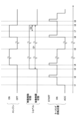
次に、図4を参照し、エンジン11の状態と、ショベルPSの状態と、キーシリンダ73の回転位置との関係について説明する。図4は、エンジン11の状態、ショベルPSの状態、及び、キーシリンダ73の回転位置のそれぞれの時間的推移を示す図である。Next, the relationship between the state of the
図4は、エンジン11が「OFF」で、且つ、ショベルPSが「始動制限状態」にある時刻t1において、キーシリンダ73の回転位置が「ACC」から「ON」に切り換えられたことを示している。エンジン11に関する「OFF」は、エンジン11が稼動していない状態を表す。エンジン11に関する「ON」は、エンジン11が稼動している状態を表す。
Figure 4 shows that at time t1 when the
また、図4は、エンジン11が「OFF」で、且つ、ショベルPSが「始動制限状態」にある時刻t2において、キーシリンダ73の回転位置が「ON」から「START」に切り換えられたことを示している。この場合、ショベルPSの操作者は、キーシリンダ73を「START」まで回転させたとしてもエンジン11を始動できない。ショベルPSが「始動制限状態」となっているためである。
Figure 4 also shows that at time t2 when the
また、図4は、エンジン11が「OFF」で、且つ、キーシリンダ73の回転位置が「ON」である時刻t3において、ショベルPSが「始動制限状態」から「制限解除状態」に切り換えられたことを示している。これは、時刻t3において、図3で示すような認証情報の照合が行われた結果、第1パスワードと第2パスワードとが一致するとコントローラ30が判定したことを表している。なお、図4の例では、認証情報の有効期間は、「制限解除状態」が時刻t8まで期間D1にわたって継続するように予め設定されている。
Figure 4 also shows that the excavator PS is switched from the "start restricted state" to the "restriction released state" at time t3 when the
そのため、その後の時刻t4において、ショベルPSの操作者は、キーシリンダ73を「START」まで回転させることで、エンジン11を始動させることができる。ショベルPSが「制限解除状態」となっているためである。Therefore, at a later time t4, the operator of the shovel PS can start the
図4の例では、認証情報の有効期間は、上述のように、制限解除状態が時刻t8までの期間D1にわたって継続するように設定されている。そのため、時刻t5において、キーシリンダ73の回転位置が「ON」から「ACC」に切り換えられた場合であっても、エンジン11は「OFF」となるが、ショベルPSは「制限解除状態」のまま維持される。その結果、時刻t6において、操作者は、キーシリンダ73の回転位置を「ACC」から再び「START」に切り換えることで、再認証を受けることなく、エンジン11を再始動させることができる。すなわち、操作者は、携帯端末200の画面にQRコードを再表示させることなく、エンジン11を再始動させることができる。
In the example of FIG. 4, the validity period of the authentication information is set so that the unrestricted state continues for the period D1 up to time t8, as described above. Therefore, even if the rotational position of the
その後、コントローラ30は、認証情報の有効期間が満了する時刻である時刻t8よりも所定時間D2だけ早い時刻t7において、「XX分後にエンジンが停止します」といったメッセージを表示装置40の画像表示部41に表示させる。コントローラ30は、その旨を伝える音声メッセージを音出力装置43から出力させてもよい。或いは、コントローラ30は、その旨を操作者に伝えるために任意の手段を利用してもよい。エンジン11が所定時間後に停止することをショベルPSの操作者に事前に知らせるためである。操作者は、このような通知を受けることで、作業を止める準備を早期に開始させることができる。Thereafter, at time t7, which is a predetermined time D2 earlier than time t8, at which the validity period of the authentication information expires, the
その後、時刻t8において、コントローラ30は、エンジン11を停止させる。但し、コントローラ30は、認証情報の有効期間が満了したときに、エンジン11を停止させるのではなく、油圧アクチュエータの動きを鈍化させる等、ショベルPSの動きを制限するように構成されていてもよい。Thereafter, at time t8, the
図4は、キーシリンダ73の回転位置が「ON」である時刻t8において、エンジン11が「ON」から「OFF」に切り換えられ、ショベルPSが「制限解除状態」から「始動制限状態」に切り換えられたことを示している。これは、時刻t8において、認証情報の有効期間が満了したこと、及び、エンジン11が強制的に停止させられたことを表している。
Figure 4 shows that at time t8 when the rotational position of the
時刻t9においては、ショベルPSの操作者は、キーシリンダ73を「START」まで回転させたとしても、エンジン11を始動させることができない。ショベルPSが「始動制限状態」となっているためである。At time t9, even if the operator of the shovel PS turns the
また、操作者は、時刻t3において取得したQRコードを用いたとしても、エンジン11を始動させることはできない。認証情報の有効期間が既に満了しているためである。すなわち、操作者は、管理装置90が発行する、有効期間が満了していない別の認証情報を取得しない限り、エンジン11を再始動させることができない。
Furthermore, even if the operator uses the QR code acquired at time t3, he or she cannot start the
このようにして、ショベルPSの操作者は、簡単な認証手順を実行するだけで認証を受けてエンジン11を始動させることができる。一方で、ショベルPSは、未認証の操作者によってエンジン11が不正に始動させられてしまうのを防止できる。In this way, the operator of the excavator PS can be authenticated by simply performing a simple authentication procedure and start the
次に、図5を参照し、エンジン11を始動させる手順の別の一例について説明する。図5は、エンジン11を始動させる手順の別の一例を示す図である。図5の部分図F3は、ショベルPSのキャビン10内の様子を示している。図5の例では、携帯端末200は、図4の場合と同様、通信機能、表示機能、及び入力機能等を備えたスマートフォンである。携帯端末200は、タブレットPC、ノートPC、スマートウォッチ、又は携帯電話等であってもよい。図5におけるショベルPS、管理装置90、及び携帯端末200は、図3の場合と同様、ショベル用システムの一例である、ショベルPSの盗難を防止する盗難防止システムを構成している。Next, referring to FIG. 5, another example of the procedure for starting the
最初に、ショベルPSの操作者は、メカニカルキーを利用してキャビン10のドアDRを解錠し、ドアDRを開けてキャビン10内に乗り込む。そして、操作者は、キーシリンダ73にメカニカルキーを差し込んでキーシリンダ73の回転位置を「ACC」に合わせ、表示装置40及び通信装置T1を起動させる。First, the operator of the excavator PS unlocks the door DR of the
その後、ショベルPSの操作者は、携帯端末200を操作し、矢印AR11で示すように、携帯端末200から管理装置90に要求信号を送信させる。
Then, the operator of the excavator PS operates the
ショベルPSの操作者は、キャビン10内に乗り込む前に、携帯端末200を操作して携帯端末200から管理装置90に要求信号を送信させてもよい。Before entering the
ショベルPSは、要求信号を管理装置90に送信するように構成されていてもよい。ショベルPSは、例えば、キーシリンダ73の回転位置が「OFF」から「ACC」に切り換えられたときに、矢印AR11aで示すように、管理装置90に向けて要求信号を送信してもよい。この場合、携帯端末200から管理装置90への要求信号の送信は省略されてもよい。The shovel PS may be configured to transmit a request signal to the
その後、要求信号を受けた管理装置90は、認証情報を発行し、矢印AR12で示すように、その発行した認証情報をショベルPSに向けて送信する。本実施形態では、認証情報は、所定の期間に限り有効なパスワードである。所定の期間は、例えば、発行日の午前9時から午後5時迄である。認証情報は、1回又は所定回数の始動に限り有効なパスワードであってもよい。但し、認証情報の有効期間は無期限であってもよい。Thereafter, the
図5の例では、管理装置90は、ショベルPSの操作者が携帯している携帯端末200を正規の携帯端末として予め登録している。また、管理装置90は、ショベルPSを正規のショベルとして予め登録している。また、管理装置90は、ショベルPSの操作者が携帯している携帯端末200に関する情報とショベルPSに関する情報とを対応付けている。そのため、携帯端末200から要求信号を受信すると、管理装置90は、発行した認証情報をショベルPSに送信できる。In the example of Figure 5, the
認証情報を受けたショベルPSは、認証情報を画面に表示する。本実施形態では、ショベルPSは、認証情報としてのパスワードを受信すると、そのパスワードをQRコード(登録商標)に符号化し、部分図F3で示すように、そのQRコードを表示装置40の画像表示部41に表示する。なお、QRコードは、バーコード等の他の符号化された情報であってもよい。また、符号化された情報は、動画像であってもよい。また、ショベルPSは、符号化される前の認証情報ではなく、符号化された後の認証情報を管理装置90から受けてもよい。
The excavator PS that has received the authentication information displays the authentication information on the screen. In this embodiment, when the excavator PS receives a password as authentication information, it encodes the password into a QR code (registered trademark) and displays the QR code on the
その後、操作者は、QRコードが表示された表示装置40の画像表示部41を、携帯端末200に搭載されているデジタルカメラで撮像する。そして、携帯端末200は、デジタルカメラが撮像した画像から、画像表示部41に表示されているQRコードを認識し、そのQRコードを復号化してパスワードを取得する。そして、携帯端末200は、矢印AR13で示すように、取得したパスワードを管理装置90に送信する。なお、携帯端末200は、認識したQRコードを管理装置90に送信してもよい。この場合、QRコードの復号化は、管理装置90において実行される。The operator then uses the digital camera mounted on the
その後、管理装置90は、ショベルPSに向けて送信したパスワード(以下、「第1パスワード」とする。)と、携帯端末200に搭載されているデジタルカメラが撮像した画像から抽出され且つ認識されたQRコードを復号化して得られるパスワード(以下、「第2パスワード」とする。)とを照合する。Then, the
第1パスワードと第2パスワードとが一致すると判定した場合、管理装置90は、携帯端末200を持っている操作者を正規の操作者として認証する。そして、管理装置90は、矢印AR14で示すように、ショベルPSの状態を始動制限状態から制限解除状態に切り換えるための制限解除指令をショベルPSに向けて送信する。If it is determined that the first password and the second password match, the
その後、制限解除指令を受信したショベルPSのコントローラ30は、ショベルPSの状態を始動制限状態から制限解除状態に切り換える。すなわち、コントローラ30は、キーシリンダ73の回転位置が「START」になったときにスタータモータ11bに対して始動指令を出力できる状態になる。Thereafter, the
その後、ショベルPSの操作者は、制限解除状態となったショベルPSにおいて、キーシリンダ73を「START」に回転させることで、エンジン11を始動させ、所望の作業を行うためにショベルPSを動作させることができる。Thereafter, with the shovel PS in the unrestricted state, the operator of the shovel PS can rotate the
その後、管理装置90が発行した認証情報の有効期間が満了すると、エンジン11が停止し、ショベルPSは、矢印AR15で示すように、始動制限状態となる。
Thereafter, when the validity period of the authentication information issued by the
図5の例では、管理装置90が発行した認証情報の有効期間が満了する前に操作者がキーシリンダ73を「ACC」又は「OFF」まで回転させると、エンジン11は停止するが、ショベルPSは、制限解除状態のままで維持される。この場合、操作者は、キーシリンダ73を再び「START」まで回転させることで、エンジン11を再始動させることができる。すなわち、操作者は、エンジン11を再始動させるために、表示装置40の画像表示部41にQRコードを表示させる必要はない。
In the example of FIG. 5, if the operator rotates the
但し、ショベルPSは、管理装置90が発行した認証情報の有効期間が満了する前に操作者がキーシリンダ73を「ACC」又は「OFF」まで回転させた場合であっても、始動制限状態になるように構成されていてもよい。この場合、操作者は、管理装置90が発行した認証情報の有効期間内であれば、携帯端末200を操作して携帯端末200から管理装置90に要求信号を送信し直すことで、エンジン11を再始動させることができる。However, the excavator PS may be configured to enter a start-restricted state even if the operator rotates the
図5の例において、要求信号を受けた管理装置90は、発行した認証情報を矢印AR12で示すようにショベルPSに向けて送信するだけでなく、携帯端末200にも送信するように構成されていてもよい。この場合、携帯端末200は、第2パスワードを取得したときに、管理装置90から受信したパスワードである第1パスワードと第2パスワードとが一致するか否かを判定してもよい。すなわち、第1パスワードと第2パスワードとの照合は、管理装置90ではなく携帯端末200で行われてもよい。そして、第1パスワードと第2パスワードとが一致すると判定した場合、携帯端末200は、携帯端末200を持っている操作者を正規の操作者として認証した上で、ショベルPSの状態を始動制限状態から制限解除状態に切り換えるための制限解除指令をショベルPSに向けて送信してもよい。なお、携帯端末200は、第1パスワードと第2パスワードとが一致した事実、すなわち、携帯端末200を持っている操作者を正規の操作者として認証した事実を、管理装置90に通知してもよい。管理装置90が発行した認証情報が正しく使われたことを管理者が認識できるようにするためである。この場合、制限解除指令は、携帯端末200からではなく管理装置90からショベルPSに向けて送信されてもよい。In the example of FIG. 5, the
上述の構成により、ショベルPSは、簡単な認証手順を操作者に実行させることで、その操作者を正規の操作者として認証できる。すなわち、ショベルPSの操作者は、簡単な認証手順を実行するだけで正規の操作者としての認証を受けてエンジン11を始動させることができる。一方で、ショベルPSは、未認証の操作者によってエンジン11が不正に始動させられてしまうのを防止できる。そのため、ショベルPSは、特別な装置を追加する必要なく、盗難を防止できる。
With the above-described configuration, the shovel PS can authenticate the operator as a legitimate operator by having the operator perform a simple authentication procedure. In other words, the operator of the shovel PS can be authenticated as a legitimate operator and start the
なお、1台のショベルに対応する1つのイモビライザキーを複数の操作者で共用する場合、そのショベルを使用する予定の操作者は、イモビライザキーを所持している別の操作者からイモビライザキーを事前に受け取る必要がある。これに対し、本発明の実施形態に係るショベルPSでは、操作者は、イモビライザキーの受け渡しのような煩雑な手順を行う必要がない。 When multiple operators share one immobilizer key for one shovel, the operator who plans to use the shovel must receive the immobilizer key in advance from another operator who has the immobilizer key. In contrast, with the shovel PS according to the embodiment of the present invention, the operator does not need to go through the complicated procedure of handing over the immobilizer key.
また、本発明の実施形態に係るショベルPSでは、ショベルPSの管理者は、生体認証システムを導入する際に必要となる多数の操作者の生体情報の事前登録といった煩雑な作業を行う必要がない。 Furthermore, with the excavator PS according to an embodiment of the present invention, the administrator of the excavator PS does not need to perform cumbersome tasks such as pre-registering the biometric information of a large number of operators, which is necessary when introducing a biometric authentication system.
上述の通り、本願の実施形態に係る、外部の管理装置90と通信接続されるショベルPSは、エンジン11を備え、管理装置90が発行した認証情報を受け、その認証情報による認証結果に基づいてエンジン11の始動を許可するように構成されている。As described above, in an embodiment of the present application, the excavator PS that is communicatively connected to an
例えば、ショベルPSは、管理装置90が発行した認証情報としての第1パスワードを受信し、キャビン10内に搭載されている室内カメラ80P又はマイク等を通じて取得される第2パスワードと第1パスワードとが一致する場合、すなわち、操作者を正規の操作者として認証できるという認証結果が得られた場合に、エンジン11の始動を許可するように構成されている。「エンジン11の始動を許可する」は、例えば、コントローラ30がスタータモータ11bに対して始動指令を出力できる状態になることを意味する。For example, the excavator PS is configured to receive a first password as authentication information issued by the
ショベルPSは、例えば、管理装置90が発行した認証情報と、ショベルPSに搭載されている装置を通じて入力された認証情報とが照合できたときにエンジン11の始動を許可するように構成されていてもよい。ショベルPSに搭載されている装置は、例えば、入力装置45、室内カメラ80P、又はマイク等である。The excavator PS may be configured to permit the
例えば、ショベルPSは、管理装置90が発行した認証情報としての第1パスワードと、キャビン10内に設置されている室内カメラ80Pで撮像されたQRコードが表す認証情報としての第2パスワードとが照合できたときに、エンジン11の始動を許可するように構成されていてもよい。第2パスワードは、入力装置45を通じて手入力されてもよい。For example, the excavator PS may be configured to permit the start of the
ショベルPSは、例えば、管理装置90からの信号に基づいてエンジン11の始動を許可するように構成されていてもよい。例えば、管理装置90は、図5に示すような手順が実行され、ショベルPSに向けて送信した第1パスワードと、携帯端末200に搭載されているデジタルカメラが撮像した画像から抽出され且つ認識されたQRコードを復号化して得られる第2パスワードとが一致すると判定した場合、携帯端末200を持っている操作者を正規の操作者として認証する。そして、管理装置90は、ショベルPSの状態を始動制限状態から制限解除状態に切り換えるための制限解除指令をショベルPSに向けて送信する。ショベルPSは、制限解除指令を受信すると、制限解除状態に切り換わり、スタータモータ11bに対して始動指令を出力できる状態になる。その後、ショベルPSの操作者は、例えば、制限解除状態となったショベルPSにおいて、キーシリンダ73を「START」に回転させることで、エンジン11を始動させ、所望の作業を行うためにショベルPSを動作させることができる。The shovel PS may be configured to permit the
管理装置90が発行した認証情報は、望ましくは、所定期間に限り有効である。すなわち、管理装置90が発行した認証情報は、望ましくは、所定期間が経過した後で無効となる。この構成により、ショベルPSは、不正アクセスに対するセキュリティを高めることができる。ショベルPSの使用の度毎に新たな認証情報が発行されるため、長期間にわたって有効な暗証番号等を操作者に手入力させるシステムに比べ、認証情報の失念及び漏洩等に関する問題を軽減できるためである。その結果、ショベルPSは、建設機械レンタル業等のシェアビジネスで利用される場合の認証情報の秘匿性を高めることができる。
The authentication information issued by the
ショベルPSは、例えば図3で示すように、管理装置90から通信装置T1を通じて受信した認証情報である第1パスワードと、撮像装置80(室内カメラ80P)を通じて入力された認証情報である第2パスワードとが照合できたときにエンジン11の始動を許可するように構成されていてもよい。或いは、ショベルPSは、例えば図5で示すように、管理装置90が送信した認証情報である第1パスワードと、携帯端末200を通じて入力された認証情報である第2パスワードとが照合できたときにエンジン11の始動を許可するように構成されていてもよい。この構成により、ショベルPSは、簡単な構成でエンジン11の不正な始動を防止できる。The excavator PS may be configured to permit the
以上、本発明の好ましい実施形態について詳説した。しかしながら、本発明は、上述した実施形態に制限されることはない。上述した実施形態は、本発明の範囲を逸脱することなしに、種々の変形又は置換等が適用され得る。また、別々に説明された特徴は、技術的な矛盾が生じない限り、組み合わせが可能である。
本願は、2019年8月2日に出願した日本国特許出願2019-142996号に基づく優先権を主張するものであり、この日本国特許出願の全内容を本願に参照により援用する。
The preferred embodiments of the present invention have been described above in detail. However, the present invention is not limited to the above-described embodiments. Various modifications or substitutions may be applied to the above-described embodiments without departing from the scope of the present invention. Furthermore, features described separately may be combined unless technical contradictions arise.
This application claims priority based on Japanese Patent Application No. 2019-142996, filed on August 2, 2019, the entire contents of which are incorporated herein by reference.
1・・・下部走行体 1A・・・右走行用油圧モータ 1B・・・左走行用油圧モータ 2・・・旋回機構 2A・・・旋回用油圧モータ 3・・・上部旋回体 4・・・ブーム 5・・・アーム 6・・・バケット 7・・・ブームシリンダ 8・・・アームシリンダ 9・・・バケットシリンダ 10・・・キャビン 11・・・エンジン 11a・・・オルタネータ 11b・・・スタータモータ 11c・・・水温センサ 13・・・レギュレータ 14c・・・油温センサ 15・・・パイロットポンプ 16・・・作動油ライン 17・・・コントロールバルブ 25・・・パイロットライン 26・・・操作装置 28・・・吐出圧センサ 29・・・操作圧センサ 30・・・コントローラ 30a・・・一時記憶部 40・・・表示装置 41・・・画像表示部 42・・・入力部 42a・・・ライトスイッチ 42b・・・ワイパースイッチ 42c・・・ウインドウォッシャスイッチ 43・・・音出力装置 45・・・入力装置 47・・・記憶装置 49・・・ゲートロックレバー 49a・・・ゲートロック弁 70・・・蓄電池 72・・・電装品 73・・・キーシリンダ 74・・・エンジン制御装置 75・・・エンジン回転数調整ダイヤル 80・・・撮像装置 80B・・・後カメラ 80F・・・前カメラ 80L・・・左カメラ 80P・・・室内カメラ 80R・・・右カメラ 90・・・管理装置 93・・・通信ネットワーク 200・・・携帯端末 CV・・・サイドカバー DR・・・ドア S1・・・ブーム角度センサ S2・・・アーム角度センサ S3・・・バケット角度センサ S4・・・機体傾斜センサ S5・・・旋回角速度センサ T1・・・通信装置 T2・・・GNSS受信機1: Lower traveling body 1A: Right traveling hydraulic motor 1B: Left traveling hydraulic motor 2: Swing mechanism 2A: Swing hydraulic motor 3: Upper rotating body 4: Boom 5: Arm 6: Bucket 7: Boom cylinder 8: Arm cylinder 9: Bucket cylinder 10: Cabin 11: Engine 11a: Alternator 11b: Starter motor 11c: Water temperature sensor 13: Regulator 14c: Oil temperature sensor 15: Pilot pump 16: Hydraulic oil line 17: Control valve 25: Pilot line 26: Operation device 28: Discharge pressure sensor 29: Operation pressure sensor 30: Controller 30a: Temporary memory unit 40: Display device 41: Image display unit 42: Input unit 42a: Light switch 42b: Wiper switch 42c: Window washer switch 43: Sound output device 45: Input device 47: Memory device 49: Gate lock lever 49a: Gate lock valve 70: Storage battery 72: Electrical equipment 73: Key cylinder 74: Engine control device 75: Engine speed adjustment dial 80: Imaging device 80B: Rear camera 80F: Front camera 80L: Left camera 80P: Interior camera 80R: Right camera 90: Management device 93: Communication network 200: Portable terminal CV: Side cover DR: Door S1: Boom angle sensor S2: Arm angle sensor S3: Bucket angle sensor S4: Aircraft tilt sensor S5: Turning angular velocity sensor T1: Communication device T2: GNSS receiver
Claims (12)
駆動源を備え、
前記管理装置が発行した認証情報と、携帯端末によって受信されるとともに前記ショベルに搭載されている装置を通じて入力された認証情報とが照合できたときに前記駆動源の始動を許可するように構成され、
前記ショベルに搭載されている装置は、メカニカルキーによって施錠可能なドアを有する運転室の内部に設置されており、前記メカニカルキーにより、電力が供給される状態と電力が供給されない状態とが切り換えられる、
ショベル。 A shovel that is communicatively connected to an external management device,
A drive source is provided.
the start of the drive source is permitted when authentication information issued by the management device is matched with authentication information received by a mobile terminal and input through a device mounted on the shovel,
The device mounted on the shovel is installed inside a driver's cab having a door that can be locked by a mechanical key, and the mechanical key switches between a state in which power is supplied and a state in which power is not supplied .
Shovel.
請求項1に記載のショベル。 The driving source is started using the mechanical key.
The shovel according to claim 1.
前記制御装置からの信号に基づいて前記駆動源の始動を許可する、
請求項1に記載のショベル。 A control device mounted on the shovel compares the authentication information issued by the management device with the authentication information input through a device mounted on the shovel,
permitting the start of the driving source based on a signal from the control device;
The shovel according to claim 1.
前記所定期間が満了すると、前記駆動源は停止し、或いは、前記ショベルの動きは制限される、
請求項1に記載のショベル。 The authentication information issued by the management device is valid only for a predetermined period of time,
When the predetermined period expires, the drive source is stopped or the movement of the shovel is restricted.
The shovel according to claim 1.
駆動源を備え、
前記管理装置が発行した認証情報と、前記ショベルに搭載されている表示装置と携帯端末に搭載された撮像装置とを通じて入力された認証情報とが照合できたときに前記駆動源の始動を許可するように構成され、
前記ショベルに搭載されている前記表示装置は、メカニカルキーによって施錠可能なドアを有する運転室の内部に設置されており、前記メカニカルキーにより、電力が供給される状態と電力が供給されない状態とが切り換えられる、
ショベル。 A shovel that is communicatively connected to an external management device,
A drive source is provided.
the start of the drive source is permitted when authentication information issued by the management device is collated with authentication information input via a display device mounted on the shovel and an imaging device mounted on the mobile terminal,
The display device mounted on the shovel is installed inside a driver's cab having a door that can be locked by a mechanical key, and the display device is switched between a state in which power is supplied and a state in which power is not supplied by the mechanical key .
Shovel.
請求項1に記載のショベル。 The device mounted on the shovel is an indoor camera that is provided so as to capture an image of an operator inside a cab, or a microphone that is provided so as to capture a sound played through a speaker of the mobile terminal.
The shovel according to claim 1.
前記管理装置が発行した認証情報による認証結果に基づいて駆動源の始動を許可するように構成されたショベルと、を含む、ショベル用システムであって、
前記ショベルは、前記管理装置が発行した認証情報と、携帯端末によって受信されるとともに前記ショベルに搭載されている装置を通じて入力された認証情報とが照合できたときに前記駆動源の始動を許可するように構成され、
前記ショベルに搭載されている装置は、メカニカルキーによって施錠可能なドアを有する運転室の内部に設置されており、前記メカニカルキーにより、電力が供給される状態と電力が供給されない状態とが切り換えられる、
ショベル用システム。 A management device;
A shovel configured to permit a start of a driving source based on an authentication result using authentication information issued by the management device,
the shovel is configured to permit the start of the drive source when authentication information issued by the management device is matched with authentication information received by a mobile terminal and input via a device mounted on the shovel,
The device mounted on the shovel is installed inside a driver's cab having a door that can be locked by a mechanical key, and the mechanical key switches between a state in which power is supplied and a state in which power is not supplied .
Systems for excavators.
請求項7に記載のショベル用システム。 The driving source is started using the mechanical key.
The system for a shovel according to claim 7.
前記ショベルは、前記制御装置からの信号に基づいて前記駆動源の始動を許可する、
請求項7に記載のショベル用システム。 A control device mounted on the shovel compares the authentication information issued by the management device with the authentication information input through a device mounted on the shovel,
The shovel permits the start of the driving source based on a signal from the control device.
The system for a shovel according to claim 7.
前記所定期間が満了すると、前記駆動源は停止し、或いは、前記ショベルの動きは制限される、
請求項7に記載のショベル用システム。 The authentication information issued by the management device is valid only for a predetermined period of time,
When the predetermined period expires, the drive source is stopped or the movement of the shovel is restricted.
The system for a shovel according to claim 7.
前記管理装置が発行した認証情報による認証結果に基づいて駆動源の始動を許可するように構成されたショベルと、を含む、ショベル用システムであって、
前記ショベルは、前記管理装置が発行した認証情報と、前記ショベルに搭載されている表示装置と携帯端末に搭載された撮像装置とを通じて入力された認証情報とが照合できたときに前記駆動源の始動を許可するように構成され、
前記ショベルに搭載されている前記表示装置は、メカニカルキーによって施錠可能なドアを有する運転室の内部に設置されており、前記メカニカルキーにより、電力が供給される状態と電力が供給されない状態とが切り換えられる、
ショベル用システム。 A management device;
A shovel configured to permit a start of a driving source based on an authentication result using authentication information issued by the management device,
the shovel is configured to permit the start of the drive source when authentication information issued by the management device is collated with authentication information input via a display device mounted on the shovel and an imaging device mounted on a mobile terminal,
The display device mounted on the shovel is installed inside a driver's cab having a door that can be locked by a mechanical key, and the display device is switched between a state in which power is supplied and a state in which power is not supplied by the mechanical key .
Systems for excavators.
請求項7に記載のショベル用システム。 The device mounted on the shovel is an indoor camera that is provided so as to capture an image of an operator inside a cab, or a microphone that is provided so as to capture a sound played through a speaker of the mobile terminal.
The system for a shovel according to claim 7.
Applications Claiming Priority (3)
| Application Number | Priority Date | Filing Date | Title |
|---|---|---|---|
| JP2019142996 | 2019-08-02 | ||
| JP2019142996 | 2019-08-02 | ||
| PCT/JP2020/029573 WO2021024965A1 (en) | 2019-08-02 | 2020-07-31 | Shovel and system for shovel |
Publications (2)
| Publication Number | Publication Date |
|---|---|
| JPWO2021024965A1 JPWO2021024965A1 (en) | 2021-02-11 |
| JP7702869B2 true JP7702869B2 (en) | 2025-07-04 |
Family
ID=74503845
Family Applications (1)
| Application Number | Title | Priority Date | Filing Date |
|---|---|---|---|
| JP2021537298A Active JP7702869B2 (en) | 2019-08-02 | 2020-07-31 | Excavators and systems for excavators |
Country Status (2)
| Country | Link |
|---|---|
| JP (1) | JP7702869B2 (en) |
| WO (1) | WO2021024965A1 (en) |
Families Citing this family (6)
| Publication number | Priority date | Publication date | Assignee | Title |
|---|---|---|---|---|
| CN117044193A (en) * | 2021-05-11 | 2023-11-10 | 日立建机株式会社 | Surveillance systems, surveillance devices and construction machinery |
| DE112023001286T5 (en) * | 2022-03-09 | 2025-03-06 | Sumitomo Heavy Industries, Ltd. | OPERATION ASSISTANCE DEVICE, WORKING MACHINE, REMOTE CONTROL ASSISTANCE DEVICE AND PROGRAM |
| JP2023149157A (en) * | 2022-03-30 | 2023-10-13 | 住友重機械工業株式会社 | Operation support equipment, work machines, remote operation support equipment, programs |
| JP2023131366A (en) * | 2022-03-09 | 2023-09-22 | 住友重機械工業株式会社 | Work machinery, electronic equipment |
| JP7710212B2 (en) * | 2022-04-12 | 2025-07-18 | 鹿島建設株式会社 | Construction machinery management system, control device, mobile terminal and control program |
| JP2026006522A (en) * | 2024-06-28 | 2026-01-16 | 株式会社小松製作所 | Work machine authentication system, information terminal, and work machine authentication method |
Citations (9)
| Publication number | Priority date | Publication date | Assignee | Title |
|---|---|---|---|---|
| JP2012079109A (en) | 2010-10-01 | 2012-04-19 | Toyota Motor Corp | Authentication system and authentication method |
| JP2012209664A (en) | 2011-03-29 | 2012-10-25 | Ntt Data Getronics Corp | Remote control system and method |
| JP2015124514A (en) | 2013-12-26 | 2015-07-06 | 株式会社安藤・間 | Vehicle construction machinery interlock system |
| JP2016511191A (en) | 2013-03-13 | 2016-04-14 | ルノー エス.ア.エス. | Method for making a vehicle available and corresponding system for making a vehicle available |
| JP2016196759A (en) | 2015-04-03 | 2016-11-24 | 日立建機株式会社 | Construction machinery |
| JP2017068452A (en) | 2015-09-29 | 2017-04-06 | 株式会社クボタ | Work machine operation system |
| JP2017141561A (en) | 2016-02-08 | 2017-08-17 | 株式会社デンソー | Vehicle authentication system |
| JP2019038420A (en) | 2017-08-25 | 2019-03-14 | トヨタ自動車株式会社 | Automatic driving vehicle and driverless transportation system |
| JP2019114861A (en) | 2017-12-21 | 2019-07-11 | 株式会社クボタ | Communication device of work machine, mobile terminal, communication system of work machine, and communication processing method of work machine |
-
2020
- 2020-07-31 JP JP2021537298A patent/JP7702869B2/en active Active
- 2020-07-31 WO PCT/JP2020/029573 patent/WO2021024965A1/en not_active Ceased
Patent Citations (9)
| Publication number | Priority date | Publication date | Assignee | Title |
|---|---|---|---|---|
| JP2012079109A (en) | 2010-10-01 | 2012-04-19 | Toyota Motor Corp | Authentication system and authentication method |
| JP2012209664A (en) | 2011-03-29 | 2012-10-25 | Ntt Data Getronics Corp | Remote control system and method |
| JP2016511191A (en) | 2013-03-13 | 2016-04-14 | ルノー エス.ア.エス. | Method for making a vehicle available and corresponding system for making a vehicle available |
| JP2015124514A (en) | 2013-12-26 | 2015-07-06 | 株式会社安藤・間 | Vehicle construction machinery interlock system |
| JP2016196759A (en) | 2015-04-03 | 2016-11-24 | 日立建機株式会社 | Construction machinery |
| JP2017068452A (en) | 2015-09-29 | 2017-04-06 | 株式会社クボタ | Work machine operation system |
| JP2017141561A (en) | 2016-02-08 | 2017-08-17 | 株式会社デンソー | Vehicle authentication system |
| JP2019038420A (en) | 2017-08-25 | 2019-03-14 | トヨタ自動車株式会社 | Automatic driving vehicle and driverless transportation system |
| JP2019114861A (en) | 2017-12-21 | 2019-07-11 | 株式会社クボタ | Communication device of work machine, mobile terminal, communication system of work machine, and communication processing method of work machine |
Also Published As
| Publication number | Publication date |
|---|---|
| JPWO2021024965A1 (en) | 2021-02-11 |
| WO2021024965A1 (en) | 2021-02-11 |
Similar Documents
| Publication | Publication Date | Title |
|---|---|---|
| JP7702869B2 (en) | Excavators and systems for excavators | |
| JP4616630B2 (en) | System and method for providing work machine anti-theft protection | |
| JP6965160B2 (en) | Excavator | |
| KR20170085047A (en) | Auto Security and Auto Safety System | |
| CN113544343B (en) | Excavator | |
| JP2020158997A (en) | Work machine | |
| JP6618421B2 (en) | Construction machinery | |
| CN101746350B (en) | Anti-theft system for construction machines | |
| CN110325687B (en) | Shovel, shovel control method, and portable information terminal | |
| CN107075874A (en) | Construction machinery | |
| WO2021054417A1 (en) | Excavator, excavator management device, excavator management system, and excavator assist device | |
| JP2016118033A (en) | Construction machine | |
| WO2022210858A1 (en) | Excavator | |
| US5632190A (en) | Burglarproof device for hydraulic machine | |
| JP7609688B2 (en) | STARTING SYSTEM FOR CONSTRUCTION MACHINE AND STARTING METHOD FOR CONSTRUCTION MACHINE | |
| CN119213433A (en) | Vehicle access permission control method and related device | |
| JP7704639B2 (en) | STARTING SYSTEM FOR A WORKING MACHINE, STARTING METHOD FOR A WORKING MACHINE, AND WORKING MACHINE | |
| JP2001098587A (en) | Anti-theft equipment for construction machinery | |
| JP5959886B2 (en) | Excavator | |
| JP2003097338A (en) | Work vehicle anti-theft device | |
| JP7756767B2 (en) | Excavator | |
| KR20240045268A (en) | Starting system of working machine, starting method of working machine and working machine | |
| US20250021313A1 (en) | Excavator | |
| WO2023188708A1 (en) | Management system for excavator and management method for excavator | |
| CN101364315A (en) | Finger print cipher antitheft device for vehicle |
Legal Events
| Date | Code | Title | Description |
|---|---|---|---|
| A621 | Written request for application examination |
Free format text: JAPANESE INTERMEDIATE CODE: A621 Effective date: 20230519 |
|
| A131 | Notification of reasons for refusal |
Free format text: JAPANESE INTERMEDIATE CODE: A131 Effective date: 20240305 |
|
| A521 | Request for written amendment filed |
Free format text: JAPANESE INTERMEDIATE CODE: A523 Effective date: 20240430 |
|
| A131 | Notification of reasons for refusal |
Free format text: JAPANESE INTERMEDIATE CODE: A131 Effective date: 20240730 |
|
| A521 | Request for written amendment filed |
Free format text: JAPANESE INTERMEDIATE CODE: A523 Effective date: 20240927 |
|
| A02 | Decision of refusal |
Free format text: JAPANESE INTERMEDIATE CODE: A02 Effective date: 20241224 |
|
| A521 | Request for written amendment filed |
Free format text: JAPANESE INTERMEDIATE CODE: A523 Effective date: 20250324 |
|
| TRDD | Decision of grant or rejection written | ||
| A01 | Written decision to grant a patent or to grant a registration (utility model) |
Free format text: JAPANESE INTERMEDIATE CODE: A01 Effective date: 20250610 |
|
| A61 | First payment of annual fees (during grant procedure) |
Free format text: JAPANESE INTERMEDIATE CODE: A61 Effective date: 20250624 |
|
| R150 | Certificate of patent or registration of utility model |
Ref document number: 7702869 Country of ref document: JP Free format text: JAPANESE INTERMEDIATE CODE: R150 |