JP7667843B2 - Display device - Google Patents
Display device Download PDFInfo
- Publication number
- JP7667843B2 JP7667843B2 JP2023204079A JP2023204079A JP7667843B2 JP 7667843 B2 JP7667843 B2 JP 7667843B2 JP 2023204079 A JP2023204079 A JP 2023204079A JP 2023204079 A JP2023204079 A JP 2023204079A JP 7667843 B2 JP7667843 B2 JP 7667843B2
- Authority
- JP
- Japan
- Prior art keywords
- display device
- vehicle
- light
- image
- information
- Prior art date
- Legal status (The legal status is an assumption and is not a legal conclusion. Google has not performed a legal analysis and makes no representation as to the accuracy of the status listed.)
- Active
Links
Images


Classifications
-
- G—PHYSICS
- G02—OPTICS
- G02B—OPTICAL ELEMENTS, SYSTEMS OR APPARATUS
- G02B27/00—Optical systems or apparatus not provided for by any of the groups G02B1/00 - G02B26/00, G02B30/00
- G02B27/01—Head-up displays
- G02B27/0101—Head-up displays characterised by optical features
-
- G—PHYSICS
- G02—OPTICS
- G02B—OPTICAL ELEMENTS, SYSTEMS OR APPARATUS
- G02B27/00—Optical systems or apparatus not provided for by any of the groups G02B1/00 - G02B26/00, G02B30/00
- G02B27/28—Optical systems or apparatus not provided for by any of the groups G02B1/00 - G02B26/00, G02B30/00 for polarising
- G02B27/286—Optical systems or apparatus not provided for by any of the groups G02B1/00 - G02B26/00, G02B30/00 for polarising for controlling or changing the state of polarisation, e.g. transforming one polarisation state into another
-
- B—PERFORMING OPERATIONS; TRANSPORTING
- B60—VEHICLES IN GENERAL
- B60J—WINDOWS, WINDSCREENS, NON-FIXED ROOFS, DOORS, OR SIMILAR DEVICES FOR VEHICLES; REMOVABLE EXTERNAL PROTECTIVE COVERINGS SPECIALLY ADAPTED FOR VEHICLES
- B60J1/00—Windows; Windscreens; Accessories therefor
- B60J1/02—Windows; Windscreens; Accessories therefor arranged at the vehicle front, e.g. structure of the glazing, mounting of the glazing
-
- B—PERFORMING OPERATIONS; TRANSPORTING
- B60—VEHICLES IN GENERAL
- B60K—ARRANGEMENT OR MOUNTING OF PROPULSION UNITS OR OF TRANSMISSIONS IN VEHICLES; ARRANGEMENT OR MOUNTING OF PLURAL DIVERSE PRIME-MOVERS IN VEHICLES; AUXILIARY DRIVES FOR VEHICLES; INSTRUMENTATION OR DASHBOARDS FOR VEHICLES; ARRANGEMENTS IN CONNECTION WITH COOLING, AIR INTAKE, GAS EXHAUST OR FUEL SUPPLY OF PROPULSION UNITS IN VEHICLES
- B60K35/00—Instruments specially adapted for vehicles; Arrangement of instruments in or on vehicles
- B60K35/10—Input arrangements, i.e. from user to vehicle, associated with vehicle functions or specially adapted therefor
-
- B—PERFORMING OPERATIONS; TRANSPORTING
- B60—VEHICLES IN GENERAL
- B60K—ARRANGEMENT OR MOUNTING OF PROPULSION UNITS OR OF TRANSMISSIONS IN VEHICLES; ARRANGEMENT OR MOUNTING OF PLURAL DIVERSE PRIME-MOVERS IN VEHICLES; AUXILIARY DRIVES FOR VEHICLES; INSTRUMENTATION OR DASHBOARDS FOR VEHICLES; ARRANGEMENTS IN CONNECTION WITH COOLING, AIR INTAKE, GAS EXHAUST OR FUEL SUPPLY OF PROPULSION UNITS IN VEHICLES
- B60K35/00—Instruments specially adapted for vehicles; Arrangement of instruments in or on vehicles
- B60K35/20—Output arrangements, i.e. from vehicle to user, associated with vehicle functions or specially adapted therefor
- B60K35/21—Output arrangements, i.e. from vehicle to user, associated with vehicle functions or specially adapted therefor using visual output, e.g. blinking lights or matrix displays
- B60K35/23—Head-up displays [HUD]
- B60K35/235—Head-up displays [HUD] with means for detecting the driver's gaze direction or eye points
-
- B—PERFORMING OPERATIONS; TRANSPORTING
- B60—VEHICLES IN GENERAL
- B60K—ARRANGEMENT OR MOUNTING OF PROPULSION UNITS OR OF TRANSMISSIONS IN VEHICLES; ARRANGEMENT OR MOUNTING OF PLURAL DIVERSE PRIME-MOVERS IN VEHICLES; AUXILIARY DRIVES FOR VEHICLES; INSTRUMENTATION OR DASHBOARDS FOR VEHICLES; ARRANGEMENTS IN CONNECTION WITH COOLING, AIR INTAKE, GAS EXHAUST OR FUEL SUPPLY OF PROPULSION UNITS IN VEHICLES
- B60K35/00—Instruments specially adapted for vehicles; Arrangement of instruments in or on vehicles
- B60K35/20—Output arrangements, i.e. from vehicle to user, associated with vehicle functions or specially adapted therefor
- B60K35/28—Output arrangements, i.e. from vehicle to user, associated with vehicle functions or specially adapted therefor characterised by the type of the output information, e.g. video entertainment or vehicle dynamics information; characterised by the purpose of the output information, e.g. for attracting the attention of the driver
-
- B—PERFORMING OPERATIONS; TRANSPORTING
- B60—VEHICLES IN GENERAL
- B60K—ARRANGEMENT OR MOUNTING OF PROPULSION UNITS OR OF TRANSMISSIONS IN VEHICLES; ARRANGEMENT OR MOUNTING OF PLURAL DIVERSE PRIME-MOVERS IN VEHICLES; AUXILIARY DRIVES FOR VEHICLES; INSTRUMENTATION OR DASHBOARDS FOR VEHICLES; ARRANGEMENTS IN CONNECTION WITH COOLING, AIR INTAKE, GAS EXHAUST OR FUEL SUPPLY OF PROPULSION UNITS IN VEHICLES
- B60K35/00—Instruments specially adapted for vehicles; Arrangement of instruments in or on vehicles
- B60K35/20—Output arrangements, i.e. from vehicle to user, associated with vehicle functions or specially adapted therefor
- B60K35/29—Instruments characterised by the way in which information is handled, e.g. showing information on plural displays or prioritising information according to driving conditions
-
- B—PERFORMING OPERATIONS; TRANSPORTING
- B60—VEHICLES IN GENERAL
- B60K—ARRANGEMENT OR MOUNTING OF PROPULSION UNITS OR OF TRANSMISSIONS IN VEHICLES; ARRANGEMENT OR MOUNTING OF PLURAL DIVERSE PRIME-MOVERS IN VEHICLES; AUXILIARY DRIVES FOR VEHICLES; INSTRUMENTATION OR DASHBOARDS FOR VEHICLES; ARRANGEMENTS IN CONNECTION WITH COOLING, AIR INTAKE, GAS EXHAUST OR FUEL SUPPLY OF PROPULSION UNITS IN VEHICLES
- B60K35/00—Instruments specially adapted for vehicles; Arrangement of instruments in or on vehicles
- B60K35/60—Instruments characterised by their location or relative disposition in or on vehicles
-
- B—PERFORMING OPERATIONS; TRANSPORTING
- B60—VEHICLES IN GENERAL
- B60R—VEHICLES, VEHICLE FITTINGS, OR VEHICLE PARTS, NOT OTHERWISE PROVIDED FOR
- B60R11/00—Arrangements for holding or mounting articles, not otherwise provided for
- B60R11/02—Arrangements for holding or mounting articles, not otherwise provided for for radio sets, television sets, telephones, or the like; Arrangement of controls thereof
-
- G—PHYSICS
- G03—PHOTOGRAPHY; CINEMATOGRAPHY; ANALOGOUS TECHNIQUES USING WAVES OTHER THAN OPTICAL WAVES; ELECTROGRAPHY; HOLOGRAPHY
- G03B—APPARATUS OR ARRANGEMENTS FOR TAKING PHOTOGRAPHS OR FOR PROJECTING OR VIEWING THEM; APPARATUS OR ARRANGEMENTS EMPLOYING ANALOGOUS TECHNIQUES USING WAVES OTHER THAN OPTICAL WAVES; ACCESSORIES THEREFOR
- G03B21/00—Projectors or projection-type viewers; Accessories therefor
- G03B21/54—Accessories
- G03B21/56—Projection screens
- G03B21/60—Projection screens characterised by the nature of the surface
- G03B21/62—Translucent screens
-
- B—PERFORMING OPERATIONS; TRANSPORTING
- B60—VEHICLES IN GENERAL
- B60K—ARRANGEMENT OR MOUNTING OF PROPULSION UNITS OR OF TRANSMISSIONS IN VEHICLES; ARRANGEMENT OR MOUNTING OF PLURAL DIVERSE PRIME-MOVERS IN VEHICLES; AUXILIARY DRIVES FOR VEHICLES; INSTRUMENTATION OR DASHBOARDS FOR VEHICLES; ARRANGEMENTS IN CONNECTION WITH COOLING, AIR INTAKE, GAS EXHAUST OR FUEL SUPPLY OF PROPULSION UNITS IN VEHICLES
- B60K2360/00—Indexing scheme associated with groups B60K35/00 or B60K37/00 relating to details of instruments or dashboards
- B60K2360/16—Type of output information
- B60K2360/177—Augmented reality
-
- B—PERFORMING OPERATIONS; TRANSPORTING
- B60—VEHICLES IN GENERAL
- B60K—ARRANGEMENT OR MOUNTING OF PROPULSION UNITS OR OF TRANSMISSIONS IN VEHICLES; ARRANGEMENT OR MOUNTING OF PLURAL DIVERSE PRIME-MOVERS IN VEHICLES; AUXILIARY DRIVES FOR VEHICLES; INSTRUMENTATION OR DASHBOARDS FOR VEHICLES; ARRANGEMENTS IN CONNECTION WITH COOLING, AIR INTAKE, GAS EXHAUST OR FUEL SUPPLY OF PROPULSION UNITS IN VEHICLES
- B60K2360/00—Indexing scheme associated with groups B60K35/00 or B60K37/00 relating to details of instruments or dashboards
- B60K2360/20—Optical features of instruments
- B60K2360/25—Optical features of instruments using filters
-
- B—PERFORMING OPERATIONS; TRANSPORTING
- B60—VEHICLES IN GENERAL
- B60K—ARRANGEMENT OR MOUNTING OF PROPULSION UNITS OR OF TRANSMISSIONS IN VEHICLES; ARRANGEMENT OR MOUNTING OF PLURAL DIVERSE PRIME-MOVERS IN VEHICLES; AUXILIARY DRIVES FOR VEHICLES; INSTRUMENTATION OR DASHBOARDS FOR VEHICLES; ARRANGEMENTS IN CONNECTION WITH COOLING, AIR INTAKE, GAS EXHAUST OR FUEL SUPPLY OF PROPULSION UNITS IN VEHICLES
- B60K2360/00—Indexing scheme associated with groups B60K35/00 or B60K37/00 relating to details of instruments or dashboards
- B60K2360/20—Optical features of instruments
- B60K2360/31—Virtual images
-
- B—PERFORMING OPERATIONS; TRANSPORTING
- B60—VEHICLES IN GENERAL
- B60K—ARRANGEMENT OR MOUNTING OF PROPULSION UNITS OR OF TRANSMISSIONS IN VEHICLES; ARRANGEMENT OR MOUNTING OF PLURAL DIVERSE PRIME-MOVERS IN VEHICLES; AUXILIARY DRIVES FOR VEHICLES; INSTRUMENTATION OR DASHBOARDS FOR VEHICLES; ARRANGEMENTS IN CONNECTION WITH COOLING, AIR INTAKE, GAS EXHAUST OR FUEL SUPPLY OF PROPULSION UNITS IN VEHICLES
- B60K2360/00—Indexing scheme associated with groups B60K35/00 or B60K37/00 relating to details of instruments or dashboards
- B60K2360/20—Optical features of instruments
- B60K2360/33—Illumination features
- B60K2360/349—Adjustment of brightness
-
- B—PERFORMING OPERATIONS; TRANSPORTING
- B60—VEHICLES IN GENERAL
- B60K—ARRANGEMENT OR MOUNTING OF PROPULSION UNITS OR OF TRANSMISSIONS IN VEHICLES; ARRANGEMENT OR MOUNTING OF PLURAL DIVERSE PRIME-MOVERS IN VEHICLES; AUXILIARY DRIVES FOR VEHICLES; INSTRUMENTATION OR DASHBOARDS FOR VEHICLES; ARRANGEMENTS IN CONNECTION WITH COOLING, AIR INTAKE, GAS EXHAUST OR FUEL SUPPLY OF PROPULSION UNITS IN VEHICLES
- B60K35/00—Instruments specially adapted for vehicles; Arrangement of instruments in or on vehicles
- B60K35/20—Output arrangements, i.e. from vehicle to user, associated with vehicle functions or specially adapted therefor
- B60K35/21—Output arrangements, i.e. from vehicle to user, associated with vehicle functions or specially adapted therefor using visual output, e.g. blinking lights or matrix displays
- B60K35/22—Display screens
-
- B—PERFORMING OPERATIONS; TRANSPORTING
- B60—VEHICLES IN GENERAL
- B60K—ARRANGEMENT OR MOUNTING OF PROPULSION UNITS OR OF TRANSMISSIONS IN VEHICLES; ARRANGEMENT OR MOUNTING OF PLURAL DIVERSE PRIME-MOVERS IN VEHICLES; AUXILIARY DRIVES FOR VEHICLES; INSTRUMENTATION OR DASHBOARDS FOR VEHICLES; ARRANGEMENTS IN CONNECTION WITH COOLING, AIR INTAKE, GAS EXHAUST OR FUEL SUPPLY OF PROPULSION UNITS IN VEHICLES
- B60K35/00—Instruments specially adapted for vehicles; Arrangement of instruments in or on vehicles
- B60K35/40—Instruments specially adapted for improving the visibility thereof to the user, e.g. fogging prevention or anti-reflection arrangements
- B60K35/425—Anti-reflection arrangements
-
- G—PHYSICS
- G02—OPTICS
- G02B—OPTICAL ELEMENTS, SYSTEMS OR APPARATUS
- G02B27/00—Optical systems or apparatus not provided for by any of the groups G02B1/00 - G02B26/00, G02B30/00
- G02B27/01—Head-up displays
- G02B27/0101—Head-up displays characterised by optical features
- G02B2027/0118—Head-up displays characterised by optical features comprising devices for improving the contrast of the display / brillance control visibility
- G02B2027/012—Head-up displays characterised by optical features comprising devices for improving the contrast of the display / brillance control visibility comprising devices for attenuating parasitic image effects
-
- G—PHYSICS
- G02—OPTICS
- G02B—OPTICAL ELEMENTS, SYSTEMS OR APPARATUS
- G02B27/00—Optical systems or apparatus not provided for by any of the groups G02B1/00 - G02B26/00, G02B30/00
- G02B27/01—Head-up displays
- G02B2027/0192—Supplementary details
- G02B2027/0194—Supplementary details with combiner of laminated type, for optical or mechanical aspects
Landscapes
- Engineering & Computer Science (AREA)
- Mechanical Engineering (AREA)
- Chemical & Material Sciences (AREA)
- Combustion & Propulsion (AREA)
- Transportation (AREA)
- Physics & Mathematics (AREA)
- General Physics & Mathematics (AREA)
- Optics & Photonics (AREA)
- Instrument Panels (AREA)
- Optical Elements Other Than Lenses (AREA)
- Fittings On The Vehicle Exterior For Carrying Loads, And Devices For Holding Or Mounting Articles (AREA)
- Devices For Indicating Variable Information By Combining Individual Elements (AREA)
Description
本発明は、自動車や電車や航空機等(以下では、総称して「車両」と言う)のフロントガラスやリアガラスやサイドガラス等、または、コンバイナなどに映像光を投射して表示する車両情報表示装置に関し、特に、映像情報をフロントガラスやリアガラス等を介して反射または透過し、車両の内部または外部に対して一方向に表示することが可能な車両情報表示装置および車両用情報表示システムに関する。 The present invention relates to a vehicle information display device that projects and displays image light onto the windshield, rear window, side window, or combiner of an automobile, train, airplane, etc. (hereinafter collectively referred to as "vehicle"), and in particular to a vehicle information display device and vehicle information display system that can reflect or transmit image information through the windshield, rear window, etc., and display it in one direction to the inside or outside of the vehicle.
自動車のフロントガラスやコンバイナに映像光を投射して虚像を形成しルート情報や渋滞情報などの交通情報や燃料残量や冷却水温度等の自動車情報を表示する、いわゆる、ヘッドアップディスプレイ(HUD:Head-Up-Display)装置は、例えば、特許文献1などにより既に知られている。
Head-Up-Display (HUD) devices, which project image light onto the windshield or combiner of an automobile to form a virtual image and display traffic information such as route information and congestion information, and automobile information such as remaining fuel and coolant temperature, are already known, for example from
この種の情報表示装置においては、一般的に、運転者の視点の移動を低減することを目的として映像情報を虚像として監視可能とするため、映像表示装置に表示された映像を、凹面ミラー(凸レンズの作用)を含む光学系を用いて運転者の視点に投射するものが多く採用されている。 In this type of information display device, the image displayed on the image display device is generally projected to the driver's viewpoint using an optical system that includes a concave mirror (acts like a convex lens) so that the image information can be monitored as a virtual image with the aim of reducing the movement of the driver's viewpoint.
また、この種の情報表示装置とは異なるが、一般に、スクリーンを備えた映像表示装置において利用されるスクリーンとして、バインダや微粒子を含む光拡散層を備えた透明スクリーンまたは反射型スクリーンは、既に以下の特許文献2および3により既に知られている。
Although different from this type of information display device, a transparent screen or a reflective screen with a light diffusion layer containing binders or fine particles is generally used as a screen in an image display device having a screen, and is already known from the following
上述した従来技術であるヘッドアップディスプレイ方式の車両情報表示装置では、運転者から車両外部の視界を妨げることのないよう、虚像であるAR(Augmented-Reality=拡張現実)情報を表示する。しかしながら、例えば、地図などの情報を表示する場合には、表示された地図情報が外部の視界の妨げとなってしまうことがある。また、かかる車両情報表示装置では、表示可能な領域を拡大することが望まれる一方、虚像が高解像度で視認性が高いことも要求されている。そのため、高品位な映像が容易に得られ、かつ、安価であることから、液晶表示素子(液晶表示パネル)が用いることが多いが、一方で、セットの小型化のためには、小型の液晶表示素子が用いられることから、得られる投射画像の解像度が不足し、例えばスマートフォンなどに表示される高解像度な映像を表示するには不向きであると言う新たな課題が明確になった。 In the vehicle information display device of the above-mentioned conventional technology using a head-up display, AR (Augmented Reality) information, which is a virtual image, is displayed so as not to obstruct the driver's view of the outside of the vehicle. However, when displaying information such as a map, the displayed map information may obstruct the view of the outside. In addition, while it is desirable to expand the displayable area of such a vehicle information display device, it is also required that the virtual image has high resolution and high visibility. For this reason, liquid crystal display elements (liquid crystal display panels) are often used because they can easily produce high-quality images and are inexpensive. However, on the other hand, a small liquid crystal display element is used to reduce the size of the set, and this has revealed a new problem that the resolution of the projected image obtained is insufficient and it is not suitable for displaying high-resolution images displayed on a smartphone, for example.
また、かかるヘッドアップディスプレイ方式の車両情報表示装置は、車両の外部に対して映像情報を表示することを目的とするものではない。そのため、車両の外部に対して映像情報を表示しようとする場合、車両の内部にディスプレイ等の映像表示装置等を搭載し、車両のガラス越しに当該映像情報を表示することが行われる。しかしながら、その場合、これらの映像表示装置が運転者の視界を妨害することとなり、安全運転上も好ましくない。 Furthermore, such head-up display type vehicle information display devices are not intended to display video information to the outside of the vehicle. Therefore, when attempting to display video information to the outside of the vehicle, a video display device such as a display is installed inside the vehicle and the video information is displayed through the vehicle glass. However, in such cases, these video display devices obstruct the driver's field of vision, which is undesirable from the perspective of safe driving.
なお、従来技術である特許文献2および3では、情報表示装置において利用されるバインダや微粒子を含む光拡散層を備えた反射型スクリーンまたは透明スクリーンが開示されているが、本発明が関わる車両における応用やそのための具体的な方法や形態や構成については何ら教示されていない。
Note that, although the prior
本発明は、従来のヘッドアップディスプレイ方式の車両情報表示装置に代え、車両のシールドガラスであるフロントガラス(更には、リアガラスやサイドガラス)を介して高解像度な映像情報が表示可能であって、その場合、表示された映像情報は、車両内部においては運転者を含む搭乗(同乗)者からは視認可能であるが、他方、車両の外部からは不可能であり、あるいは、車両の外部からは視認可能であるが、他方、車両の内部の搭乗(同乗)者からは不可能である、いわゆる、一方向性の表示が可能な車両情報表示装置を提供することを目的とする。更には、かかる車両情報表示装置を利用した車両用情報表示システムを提供することを目的とする。 The present invention aims to provide a vehicle information display device that can display high-resolution video information through the windshield (and even the rear and side windows), which is the shield glass of the vehicle, in place of conventional head-up display type vehicle information display devices, and in which the displayed video information is visible to passengers (including the driver) inside the vehicle but not from outside the vehicle, or is visible from outside the vehicle but not from passengers (including the driver) inside the vehicle, i.e., a so-called unidirectional display. A further aim is to provide an information display system for vehicles that utilizes such a vehicle information display device.
本発明では、上述した目的を達成するため、
表示装置であって、映像光を出射する表示パネルと、前記表示パネルから出射された映像光に含まれる特定の偏波を吸収する偏光板と、を備え、前記表示パネルから出射され、前記特定の偏波が吸収された映像光を、車両のシールドガラスで反射させることで、前記表示パネルで生成した映像を虚像として前記車両の運転者へ向けて表示する、表示装置が提供される。
In order to achieve the above-mentioned object, the present invention provides
The present invention provides a display device comprising a display panel that emits image light, and a polarizing plate that absorbs a specific polarized wave contained in the image light emitted from the display panel, and which reflects the image light emitted from the display panel and from which the specific polarized wave has been absorbed by a shield glass of a vehicle, thereby displaying an image generated by the display panel as a virtual image to a driver of the vehicle.
本発明によれば、高解像度な映像情報を一方向に表示が可能な車両情報表示装置が提供され、更には、かかる車両情報表示装置を利用した新規で利用性に優れた車両用の情報表示システムが提供されるという効果を発揮する。 The present invention provides a vehicle information display device capable of displaying high-resolution image information in one direction, and further provides a novel and highly usable information display system for vehicles that utilizes the vehicle information display device.
以下、図面等を用いて、本発明の実施の形態について詳細に説明する。なお、本発明は以下の説明に限定されるものではなく、本明細書に開示される技術的思想の範囲内において当業者による様々な変更および修正が可能である。また、本発明を説明するための全図において、同一の機能を有するものには、同一の符号を付与し、その繰り返しの説明は省略する場合がある。 The following describes in detail the embodiments of the present invention with reference to the drawings. Note that the present invention is not limited to the following description, and various changes and modifications can be made by those skilled in the art within the scope of the technical ideas disclosed in this specification. In addition, in all drawings used to explain the present invention, parts having the same functions are given the same reference numerals, and repeated explanations of such parts may be omitted.
<車両情報表示システム>
図1(a)は、本発明の一実施の形態に係る車両情報表示装置100を、自動車や電車や航空機等のうち、特に、自動車に搭載した場合の上面図である。自動車本体1の運転席前部には、映像光を投射して表示するための透光性の被投射部材としてのフロントガラス6、リアガラス6’、サイドガラス6”等(総称して「シールドガラス」とも言う)が存在する。特に、フロントガラス6は自動車のタイプによって車体に対する傾斜角度が異なる。発明者らは最適な虚像光学系を実現するためこの曲率半径も調査した。その結果、フロントガラス6は、図1(b)に示すように、自動車の接地面に対して水平な水平方向の曲率半径Rhと水平軸に対して垂直方向の曲率半径Rvとでは異なり、RhとRvの間には一般に下記の関係が成り立つことが判った。
Rh>Rv
また、この曲率半径の違い、即ち、Rvに対するRhは1.5倍から2.5倍の範囲にあるものが多いことも判明した。
<Vehicle information display system>
FIG. 1(a) is a top view of a vehicle
Rh>Rv
It was also found that the difference in the radius of curvature, that is, the ratio Rh to Rv, is often in the range of 1.5 to 2.5 times.
本発明は、車両の一部を構成する被投射部材としてのフロントガラス6、リアガラス6’、および/または、サイドガラス6”を介して、運転者が自車を運転する際には、車両内部の運転者や同乗者に映像情報を監視させ、他方、車両の外部に対しても映像情報を表示することが可能なシステムに関する。その結果、運転者や同乗者は、必要な情報をフロントガラス6などの表示領域に適宜表示して、車両内で監視することができるが、他方、車両の外部からは、当該情報を監視することはできない。あるいは、リアガラス6’やサイドガラス6”(フロントガラス6を含んでもよい)を介して、車両の外部に対しても映像情報を表示することができ、この表示した情報は外部からは監視可能であるが、車内からは監視できず、運転者や同乗者が外部の景観を監視することを妨げることなく、運転の妨げとはならない。
The present invention relates to a system that allows the driver and passengers inside the vehicle to monitor video information while driving the vehicle through the
また、太陽光などの自然光は、図16に示すように紫外線から赤外線までの幅広い波長領域の光であるばかりでなく、偏光方向も光の進行方向に垂直な振動方向の光と水平方向の光である2種類の偏光方向(以下S偏光とP偏光と記載)の光とが混ざった状態で存在する。特に、フロントガラス6への入射角度が50度を超えるような領域では図15に示すように、ガラス面上での反射率は、S偏光やP偏光、更には、入射角によりそれぞれ異なる。
Natural light such as sunlight not only consists of light in a wide wavelength range from ultraviolet to infrared as shown in Figure 16, but also exists in a state where light has two different polarization directions (hereinafter referred to as S-polarized and P-polarized light), namely light with a vibration direction perpendicular to the light's direction of travel and light with a horizontal direction, are mixed together. In particular, in areas where the angle of incidence on the
そこで、本実施の形態では、上述した発明者による知見に基づき、即ち、フロントガラス6を通して侵入する太陽光の多くはP偏光成分であることを考慮し、情報表示装置内に侵入する太陽光を含む外光を抑制するためには、特に、P波成分の低減が有効であること、加えて、情報表示装置から投射される映像光としては、S波成分を利用することが効果的であることを確認した。
Therefore, in this embodiment, based on the findings of the inventors described above, that is, taking into consideration that most of the sunlight that enters through the
続いて、図2を参照しながら、本発明になる車両用情報表示システムを構成する車両情報表示装置について、その具体的な構成について、以下に図面を参照しながら詳細に説明する。 Next, with reference to FIG. 2, the specific configuration of the vehicle information display device constituting the vehicle information display system of the present invention will be described in detail below with reference to the drawings.
<車両情報表示装置の具体的な構成1>
図2は、映像情報を、車両の一部を構成する透明な被投射部材であるフロントガラス6を介して、運転者が監視する外部景観の一部に表示する車両情報表示装置100の全体構成を示している。ここでは、フロントガラス6を複数の領域に分割してその一部領域(本例では、フロントガラス6の下部)に映像表示装置(映像投射装置)48からの映像光をフロントガラス6で拡散・反射させ、その反射像を、直接、運転者や同乗者が一方向に監視する。この結果、運転者や同乗者は、必要な情報をフロントガラス6の表示領域に、適宜、表示して監視することができ、他方、車両の外部からは、当該情報を視認することはできない。
<
2 shows the overall configuration of a vehicle
車両情報表示装置100では、映像表示装置48は、図2にも示すように、例えば、スマートフォン300等からの高解像度の地図情報(大型高解像度の映像表示装置の映像)を、以下にも詳述するが、光方向変換パネル54や保護カバー50を介して、フロントガラス6の内側表面に投射し、当該フロントガラス6の表面に設けた透明シート(フィルム)51で監視者(運転者)の眼8に向かって反射させることで、フロントガラス6上に映像を表示する。
As shown in FIG. 2, in the vehicle
なお、この例では、地図情報等を提供するナビゲーション機能を搭載した高性能の携帯端末装置であるスマートフォン300を利用する場合の一例を示しており、スマートフォン300からの表示画面が、有線の接続端子を介して、または、Bluetooth(登録商標)やWifi(登録商標)等の無線によって入力されてその映像を表示することが可能となっており、これにより、運転者は、車両情報表示装置100を利用して、高解像度の映像情報を監視することができる。
This example shows an example of using a
なお、ここでは図示しないが、スマートフォン300は、映像表示装置48と同様、CPU(Central Processing Unit)、ワークメモリや情報蓄積・記憶手段としての機能を有するRAMやROM等の各種の固体メモリ等により構成された制御部を備えており、必要な映像を生成してその表示装置(液晶ディスプレイ)に表示する機能を備えていることは当然であろう。
Although not shown here, the
更に、車両情報表示装置100のより具体的な構成について、図3を用いて説明する。映像表示装置48を構成する液晶表示パネル(映像表示素子)52は、例えば、画面サイズが6インチを超える比較的大型な液晶表示パネルにより構成される。一般的に、フロントガラス6の曲率半径は部分的に異なることが多いため、映像を反射させる場所によって表示映像に不均一(縦方向と横方向)な歪が発生する。このため監視方向から反射像を見た場合に正しい映像を得るために歪補正が必要となる。この歪補正によって実用上問題のないレベルの補正を行うにはパネルの解像度は1280×720ドット以上が必要となる。
Furthermore, a more specific configuration of the vehicle
また、映像表示装置48は、上述した液晶表示パネル52と共に、その光源を構成する光源装置101を備えており、図3では、光源装置101を、液晶表示パネル52と共に、その下方に展開斜視図として示している。
The
この液晶表示パネル(映像表示素子)52は、図3にも示すように、バックライト装置である光源装置101により指向性の強い照明光束を得て、入力される映像信号に応じで変調をかけた映像光を、フロントガラス6に設けた透明シート51に向かって出射する。
As shown in FIG. 3, this liquid crystal display panel (image display element) 52 obtains a highly directional illumination light beam from a
また、この図3では、車両情報表示装置100は、映像表示装置48を構成する液晶表示パネル52と共に、更に、光源装置101からの出射光束30の指向特性を制御する光方向変換パネル54、および、必要に応じて挟角拡散板を備えて構成されている。即ち、液晶表示パネル52の両面には偏光板が設けられ、特定の偏波の映像光が映像信号により光の強度を変調して出射する構成となっている。これにより、スマートフォン300等からの高解像度の映像(大型高解像度の映像表示装置の映像)を、光方向変換パネル54を介してフロントガラス6に向けて投射し、その表面に設けた透明シート51を介して、監視者(運転者)の眼8に向けて反射する。
In FIG. 3, the vehicle
なお、光源装置101は、図4にも示すように、例えば、プラスチックなどにより形成され、その内部に後にも詳述するLED素子、コリメータ、合成拡散ブロック、導光体等を収納した光源装置101のケース(図3参照)から構成されており、その上面には、映像表示装置48を構成する液晶表示パネル52が取り付けられている。また、光源装置101のケースのひとつの側面には、半導体光源であるLED(Light Emitting Diode)素子14a、14bや、その制御回路を実装したLED基板102が取り付けられると共に、当該LED基板102の外側面には、上記LED素子および制御回路で発生する熱を冷却するための部材であるヒートシンク103が取り付けられている(図3参照)。
As shown in FIG. 4, the
他方、光源装置ケース101の上面に取り付けられた映像表示装置48は、液晶表示パネルフレームと、当該フレームに取り付けられた液晶表示パネル52と、更に、液晶表示パネル52に電気的に接続されたFPC(Flexible Printed Circuits:フレキシブル配線基板)403(図3参照)などから構成されている。即ち、液晶表示素子である液晶表示パネル52は、後にも詳細に説明するが、固体光源であるLED素子14a,14bと共に、電子装置を構成する制御回路(ここでは図示せず)からの制御信号に基づいて透過光の強度を変調することによって表示映像を生成する。
On the other hand, the
続いて、光源装置101の構成、即ち、光源装置ケース内に収納されている光学系の一例について、以下に、図4と共に、図5を参照しながら、詳細に説明する。
Next, the configuration of the
図4および図5には、光源を構成する複数(本例では、2個)のLED素子14a、14bが示されており、これらはLEDコリメータ15に対して所定の位置に取り付けられている。なお、このLEDコリメータ15は、各々、例えば、アクリル等の透光性の樹脂により形成されている。そして、このLEDコリメータ15は、図5(b)にも示すように、放物断面を回転して得られる円錐凸形状の外周面156を有すると共に、LEDコリメータ15の頂部では、その中央部に凸部(即ち、凸レンズ面)157を形成した凹部153を有する。また、LEDコリメータ15の平面部の中央部には、外側に突出した凸レンズ面(あるいは、内側に凹んだ凹レンズ面でもよい)154を有している。なお、LEDコリメータ15の円錐形状の外周面を形成する放物面156は、LED素子14aから周辺方向に出射する光をその内部で全反射することが可能な角度の範囲内において設定され、あるいは、反射面が形成されている。
4 and 5 show a plurality of (two in this example)
他方、LED素子14a、14bは、その回路基板である、いわゆる、LED基板102の表面上の所定の位置にそれぞれ配置されている。このLED基板102は、LEDコリメータ15に対して、その表面上のLED素子14aまたはLED素子14bが、それぞれ、その凹部153の中央部に位置するように配置されて固定される。
On the other hand, the
かかる構成によれば、上述したLEDコリメータ15によって、LED素子14aまたはLED素子14bから放射される光のうち、特に、その中央部分から上方(図の右方向)に向かって放射される光は、LEDコリメータ15の外形を形成する2つの凸レンズ面157、154により集光されて平行光となる。また、その他の部分から周辺方向に向かって出射される光は、LEDコリメータ15の円錐形状の外周面を形成する放物面によって反射され、同様に、集光されて平行光となる。換言すれば、その中央部に凸レンズを構成すると共に、その周辺部に放物面を形成したLEDコリメータ15によれば、LED素子14aまたはLED素子14bにより発生された光のほぼ全てを平行光として取り出すことが可能となり、発生した光の利用効率を向上することが可能となる。
According to this configuration, the light emitted from the
なお、LEDコリメータ15の光の出射側には、以下にも詳述する偏光変換素子21が設けられている。この偏光変換素子21は、図5(a)からも明らかなように、断面が平行四辺形である柱状(以下、平行四辺形柱)の透光性部材と、断面が三角形である柱状(以下、三角形柱)の透光性部材とを組み合わせ、LEDコリメータ15からの平行光の光軸に対して直交する面に平行に、複数、アレイ状に配列して構成されている。更に、これらアレイ状に配列された隣接する透光性部材間の界面には、交互に、偏光ビームスプリッタ(以下、「PBS」と省略する)膜211と反射膜212とが設けられており、また、偏光変換素子21へ入射してPBS膜211を透過した光が出射する出射面には、1/2λ位相板213が備えられている。
The light exit side of the
この偏光変換素子21の出射面には、更に、図5(a)にも示す矩形状の合成拡散ブロック16が設けられている。即ち、LED素子14aまたはLED素子14bから出射された光は、LEDコリメータ15の働きにより平行光となって合成拡散ブロック16へ入射し、出射側のテクスチャー161により拡散された後、以下に述べる導光体17に到る。
The exit surface of this
導光体17は、例えば、アクリル等の透光性の樹脂により断面が略三角形(図5(b)参照)の棒状に形成された部材であり、そして、図4および図5からも明らかなように、上記合成拡散ブロック16の出射面に第1の拡散板18aを介して対向する導光体光入射部(導光体光入射面)171と、斜面を形成する導光体光反射部(導光体光反射面)172と、第2の拡散板18bを介して液晶表示素子の液晶表示パネル52と対向する導光体光出射部(導光体光出射面)173とを備えている。
The
この導光体17の導光体光反射部172には、図4にも示すように、多数の反射面172aと連接面172bとが交互に鋸歯状に形成されている。そして、反射面172a(図では右上がりの線分)は、図において一点鎖線で示す水平面に対してαn(n:自然数であり、本例では、例えば、1~130である)を形成している。その一例として、ここでは、αnは43度以下(但し、0度以上)に設定されている。
As shown in Figure 4, the light guide
導光体光入射部171は、光源側に傾斜した湾曲の凸形状に形成されている。これによれば、合成拡散ブロック16の出射面からの平行光は、第1の拡散板18aを介して拡散されて導光体17へ入射し、図4からも明らかなように、導光体光入射部171により上方に僅かに屈曲(偏向)しながら導光体光反射部172に達し、ここで反射して図の上方の出射面に設けた液晶表示パネル52に到る。
The light guide
以上に詳述したように、上述した車両情報表示装置100の映像表示装置48によれば、光利用効率やその均一な照明特性をより向上すると同時に、モジュール化されたS偏光波の光源装置を含め、小型かつ低コストで製造することが可能となる。なお、上記の説明では、偏光変換素子21をLEDコリメータ15の後に取り付けるものとして説明したが、本実施の形態はそれに限定されることなく、液晶表示パネルに至る光路中に設けることによっても同様の作用・効果が得られることは、当業者であれば明らかであろう。
As described above in detail, the
なお、導光体光反射部172には、多数の反射面172aと連接面172bとが交互に鋸歯状に形成されており、照明光束は、各々の反射面172a上で全反射されて上方に向かい、更には、導光体光出射部173には挟角拡散板を設けて略平行な拡散光束として指向特性を制御する光方向変換パネル54に入射し斜め方向から液晶表示パネル52へ入射する。本実施の形態では光方向変換パネル54を導光体光出射面173と液晶表示パネル52の間に設けたが液晶表示パネル52の出射面に設けても同様の効果が得られることは言うまでもない。
The light guide
<光方向変換パネル>
図6は、本発明の一実施の形態に係る車両情報表示装置100の一部を構成し、上述した映像表示装置48の上面に設けられる光方向変換パネル54の原理を説明するための概略説明図である。上述した光源装置101の導光体17からの光束は光方向変換パネル54の入射面(図の下面)から入射し、出射面(図の上面)に設けられたリニアフレネルレンズのレンズ作用によりに所望の方向θ3に光束を屈折させる。この時、所望の方向θ3は光束のフレネルレンズへの入射角θ2とフレネルレンズのフレネル角θ0と基材の屈折率nによりスネルの法則から一義的に導き出される。
<Light redirection panel>
6 is a schematic diagram for explaining the principle of the
この結果、導光体からの略平行光束に所望の方向に指向性を与えることができる。即ち、情報表示装置48を構成する液晶表示パネル52からの光である映像光は、車両内部の運転者や同乗者により視認されることなく、以下に述べるフロントガラス6に設けられた透明シート51へ向かう。本来その後、映像光は透明シート51によって一方向に反射・拡散されて、その反射像が運転者により視認される。
As a result, the approximately parallel light beam from the light guide can be given directivity in the desired direction. That is, the image light from the liquid
即ち、この光方向変換パネル54により、映像表示装置48(図2または図3参照)からの映像光は、それ自体が、直接、車内から視認されることはなく、そのため運転の邪魔にはなることはなく、その反射光による反射像のみが運転者や同乗者によって監視されることとなる。なお、フレネルレンズの繋ぎ面88には光吸収性の塗料や顔料を設けることで所望の方向に進む光束以外の光の発生を抑制する。この結果、ウインドガラスで反射した映像光に不要な光が混入することが無くなるので結像性能を損ねることが無くなる。
In other words, thanks to this light
<保護カバー>
図7は、ダッシュボード47に接して、光方向変換パネル54の上面に設けられる保護カバー50の概略構成を示す横断面図である。略透明な基材56の光出射側の一部にはブラックストライプ59を設け、太陽光を含めた外光の表面反射を低減するために、ブラックストライプ59は黒色塗料としてカーボンブラックを含んだ塗料を用いるとよい。またブラックストライプを設けない部分には、表面反射を抑えるため反射防止膜を設けることにより保護カバー50の表面での外光反射が大幅に軽減され、ドライバが自車を運転する際に外光反射による支障が軽減される。一方、太陽光に対する遮光性能を強化するためには近赤外光および赤外光を反射する特性を反射防止膜に持たせるとよい。
<Protective cover>
7 is a cross-sectional view showing a schematic configuration of the
他方、略透明な基材56の光入射側には、太陽光束のうちP波成分を吸収または反射する膜またはフィルム50aを、成膜または粘着する。この結果、太陽光のP波成分が映像表示装置48に入射することが無いため、耐光性や耐熱性に関する信頼性が大幅に向上する。一方、映像表示装置48からの出力されるS偏波の映像光を選択的に透過するフィルターの特性も併せ持つため、得られる映像のコントラスト性能が大幅に向上する。
On the other hand, a
なお、上述した映像表示装置48を構成する映像源が液晶表示パネル52であるため、運転者が偏光サングラスを着用している場合には、特定の偏波が遮蔽されて映像が見えない不具合が発生する。これを防ぐために、映像表示装置48の光出射側に設けた保護カバー50には、膜またはフィルム50aと基材56の間に、λ/4板またはλ/8板またはλ/16板などの波長板50bが配置されている。波長板50bを設けることにより、光束の偏光方向を特定の方向に揃え、映像光を最適な偏光角として、偏光サングラスの偏光方向と所望量偏光軸をずらすとよい。
In addition, since the image source constituting the
一方、同一偏光でも吸収軸を回転させ、例えば、偏光サングラスの吸収軸に対して液晶パネル出射側偏光板の吸収軸を30度以上ずらすことで吸収が50%程度となるため映像が見えない不具合を解消することができる。 On the other hand, even with the same polarization, by rotating the absorption axis, for example by shifting the absorption axis of the polarizing plate on the exit side of the liquid crystal panel by 30 degrees or more relative to the absorption axis of the polarized sunglasses, the absorption will be about 50%, eliminating the problem of the image not being visible.
また、偏光軸を回転させて円偏光に近づけると、情報表示装置48からの映像光はS偏光から偏光軸が回転する。このため、フロントガラス6による反射率が低下し映像の明るさが低下するので、両者のバランスを取って選択するとよい。
In addition, when the polarization axis is rotated to approach circular polarization, the polarization axis of the image light from the
<一方向性の透明シート>
次に、透明シート51の構成と作用について図8により説明する。フロントガラス6(説明の都合上、水平配置とする)に斜め方向から入射する太陽光は、そのS偏波は反射し、P偏波が透過して透明シート51に向かう。透明シート51はS波を透過する偏光板57と透明拡散シート材55および位相差板58で構成されている。この透明シート51は、屈折率の大きいナノ粒子ジルコニウムやナノ粒子ダイヤモンドを分散させた熱可塑性高分子を溶かしながら延伸したフィルム、例えば、JXTGエネルギー社製「カレイドスクリーン」を用いることで(上述した特許文献3を参照)、映像を表示していない場合には透明であり、運転者が外界(車外)の風景を監視する妨げとならず、他方、映像表示時には、映像光を拡散・反射させ、これにより、運転者や同乗者に映像情報を視認させる一方向性の表示を実現することが可能となる。この時、透明シート51の拡散透過率と平行光線透過率の比率により定義される曇度(HAZE)は10%以下であれば実用上問題ないが、望ましくは4%以下であればよい。一方、自動車用のウインドガラスのHAZUは2%以下である。
<Unidirectional transparent sheet>
Next, the configuration and function of the
映像表示装置48からの映像光はS偏波であるため斜め入射した場合の反射率が高い状態で、前述した透明拡散シート材55の内部で散乱し監視者に向かって出射する。一方、映像光の一部は散乱により偏光方向が乱れ透明拡散シート55を拡散透過してフロントガラス6に向かって出射する。フロントガラス6の入射面では屈折率差が小さいため反射光で発生する2重像のレベルは低い。これに対して、フロントガラス6の出射面(外界に接する面)で発生する反射光の強度はS偏光成分が大部分であるため反射率が大きい。この面で反射した映像光は反射後再び偏光板57を通過して吸収されるため監視者側に戻ることが無い。このためフロントガラス6の反射映像により生じる二重像が発生しなくなるので画質が大幅に向上した。なお、同様に、映像の反射面としてフロントガラス6の代わりにコンバイナに前述した透明シート51を貼っても、同様の効果が得られることは言うまでもない。
The image light from the
以上に述べた透明シート51によれば、図8にも示したように、昼間の所定条件化においてフロントガラスを通過したP偏光の太陽光成分(コンバイナ方式ではその後コンバイナも通過)を車両情報表示装置100やその上面に設けられる光方向変換パネル54や保護カバー50の手前で吸収することで、液晶表示パネルと偏光板に戻らないようにすることが可能となる。
As shown in Figure 8, the
<車両用情報表示システム>
以上に詳細に述べた車両情報表示装置100を備えた車両用情報表示システムによれば、図3において矢印で示すように、シールドガラスであるフロントガラス6の下端領域の映像表示領域に対応したダッシュボード47の位置(図2参照)に大型高解像度の映像表示装置48を設け、その表示映像をフロントガラスで反射させることにより、その反射像を、直接、運転者や同乗者に監視させることが可能となる。
<Vehicle information display system>
According to the vehicle information display system equipped with the vehicle
上述した映像表示装置48や透明シート51を含む本実施の形態の車両情報表示装置100を配置した自動車のコックピット内の配置の一例を図9に示す。図9(a)は左側にステアリングを配置した自動車に対応したシステムを、図9(b)は右側にステアリングを配置した自動車に対応したシステムを示す。図の画像表示領域(透明シート51の貼付領域に対応する)には、車両情報表示装置100を用いて映像情報をフロントガラス6で反射させ、その反射像を運転者に監視させる。その際、画像表示領域は、例えば、図に破線で示す自車両のボンネットが監視される範囲など、運転者にとって車外の景観の監視に邪魔とならない範囲や領域に設定することが好ましいであろう。
Figure 9 shows an example of the arrangement in the cockpit of an automobile in which the vehicle
上述した車両情報表示装置100は、図にも示すように、フロントガラス6とステアリング43の間のダッシュボード47の内部において、フロントガラス6から映像表示装置48の順に、ステアリング43に向け配置される。この結果、運転者が自車を運転する際にフロントガラス6を介して監視する外部の景観、即ち、フロントガラス6の一部領域に、車両情報表示装置100により、大型高解像度の映像表示装置の映像をフロントガラス6で反射させることにより、当該反射像を運転者や同乗者が監視可能な車両用情報表示システムを提供することができる。
As shown in the figure, the vehicle
なお、図9のルームミラー71にはドライバの状態監視と自動車内様子をモニタするカメラ72を設け、例えばドライバの目の高さに合わせて前述した情報表示装置からの映像光の出射方向を制御することも可能であろう。
The
図10は、上述の車両情報表示装置100に加え、助手席の同乗者にも映像情報を提供するシステムを、更には、ヘッドアップディスプレイ(HUD)装置をも搭載したシステム(図10(b))の例を示した概略図である。図10(a)は、図9と同様に、左側にステアリング43を配置した自動車に対応したシステムを、図10(b)は右側にステアリング43を配置した自動車に対応したシステムを示す。
Figure 10 is a schematic diagram showing an example of a system (Figure 10(b)) that, in addition to the vehicle
図10(a)では、上述した運転席側の車両情報表示装置100に加え、更に、助手席側にも第2の車両情報表示装置100’を搭載し、運転者が監視可能な画像表示領域(1)と共に、フロントガラス6の一部領域(図の右側)には、同乗者が監視可能な画像表示領域(2)を設定した例を示している。加えて、図10(b)では、更に、ヘッドアップディスプレイ(HUD)型の情報表示装置(ヘッドアップディスプレイ装置、以下、「HUD装置」と言う)700を搭載し、同乗者に対しては画像表示領域(2)を設定すると共に、運転者に対しては、情報表示装置48による画像表示領域(1)に加えて、HUD装置700によるHUD表示領域を設定した例を示している。
Figure 10(a) shows an example in which, in addition to the vehicle
なお、HUD装置700としては、既知の一般的な装置を採用することができるが、ここでは、その一例として、以下にその概略を説明する。
Note that a known general device can be used as the
図11は、HUD装置700をその周辺機器構成を含めて示す概略構成図であり、ここでは、運転者8の視線(アイポイント)において自車両の前方に虚像V1を形成するため、被投射部材6(フロントガラスの内面)にて反射された各種情報を虚像VI(Virtual Image)として表示する。
Figure 11 is a schematic diagram showing the
HUD装置700では、情報を表示する映像光を投射する映像表示装置704と、映像表示装置704に表示された映像を凹面(自由曲面)ミラー701で虚像を形成する際に発生する歪や収差を補正するために補正用のレンズ素子702を備えている。この情報表示装置700からの映像光束は開口部(図示せず)からフロントガラス6に向かって出射する。
The
また、HUD装置700は、更に、映像表示装置704やそのバックライトを制御する制御装置740を備えている。なお、映像表示装置704とバックライトなどを含む光学部品は虚像光学系であり、光を反射させる凹面ミラー701を含んでいる。また、この光学部品において反射した光は、被投射部材であるフロントガラス6にて反射されて運転者の視線8へと向かう。なお、映像表示装置704としては、例えば、バックライトを有するLCD(Liquid Crystal Display)の他に自発光のVFD(Vacuum Flourescent Display)などがある。
The
また、かかるHUD装置700を構成する図示の制御装置740は、ナビゲーションシステム761から、自車両が走行している現在位置に対応する道路の制限速度や車線数、ナビゲーションシステム761に設定された自車両の移動予定経路などの各種の情報を、前景情報(即ち、虚像により自車両の前方に表示する情報)として取得する。また、運転支援ECU762は、周辺監視装置763での監視の結果として検出された障害物に従って駆動系や制御系を制御することで、運転支援制御を実現するための制御装置である。かかる運転支援制御としては、例えば、クルーズコントロール、アダプティブクルーズコントロール、プリクラッシュセーフティ、レーンキーピングアシストなどの周知技術を含む。図11に示す周辺監視装置763は、自車両の周辺の状況を監視する装置であり、一例としては、自車両の周辺を撮影した画像に基づいて自車両の周辺に存在する物体を検出するカメラや、探査波を送受信した結果に基づいて自車両の周辺に存在する物体を検出する探査装置などである。
The illustrated
上述したHUD装置700の制御装置740は、このような運転支援ECU762からの情報(例えば、先行車両までの距離および先行車両の方位、障害物や標識が存在する位置など)を前景情報として取得する。更に、この制御装置740には、イグニッション(IG)信号、および、自車状態情報が入力される。これらの情報の内、自車状態情報とは、車両情報として取得される情報であり、解像度の高い表示を必要としない、例えば、内燃機関の燃料の残量や冷却水の温度など、予め規定された異常状態となったことを表す警告情報を含んでいる。また、方向指示器の操作結果や、自車両の走行速度、更には、シフトポジション情報なども含まれている。以上述べた制御装置740は、イグニッション信号が入力されると起動する。なお、被投射部材としては、情報が投影される部材であればよく、フロントガラス6だけではなく、その他、コンバイナであってもよく、運転者の視線8において自車両の前方に虚像を形成して運転者に視認させるものであればよい。
The
<車両用情報表示システムの変形例:外部への表示>
以上に詳述した実施の形態によれば、運転者が自車を運転する際に、車両を構成するシールドガラスである被投射部材としてのフロントガラス6を介して、必要な映像情報を、車両内部の運転者や同乗者に対して、一方向に、高解像度で表示して監視させることが可能となる。なお、その際、車両の外部からは、当該情報を監視することはできない。しかしながら、本発明の一実施の形態に係る車両用情報表示システムは上述した実施の形態に限定されるものではなく、その他、映像情報を車両の外部に対して表示することも可能である。即ち、上述したフロントガラス6だけではなく、更には、シールドガラスであるリアガラス6’やサイドガラス6”を介しても、同様にして、映像情報を車両内部へ、または、外部に対して表示することが可能である。
<Modification of Vehicle Information Display System: External Display>
According to the embodiment described above in detail, when the driver is driving his/her own vehicle, necessary video information can be displayed in one direction at high resolution to the driver and/or passengers inside the vehicle for monitoring through the
例えば、本実施の形態の車両用情報表示システムでは、「空車」などの車両の状態を示す情報を、タクシーのフロントガラス6の一部に、更には、リアガラス6’やサイドガラス6”にも表示し、あるいは、その他、情報宣伝・広告等の情報を、車両の外部に対して表示することも可能である。また、バスや電車などの車両においても、その路線や行先などの情報をフロントガラスやリアガラスやサイドガラスなどに、一方向に、車外に対して表示することも可能である。以下には、情報を外部に対して表示する場合の車両情報表示装置100”の構成について述べる。
For example, in the vehicle information display system of this embodiment, information indicating the vehicle status, such as "vacant," can be displayed on part of the
図12には、被投射部材としてのフロントガラス6を介して、必要な映像情報を、車両の外部に対して、一方向に、高解像度で表示して監視させるシステム、より具体的には、ここでは、タクシーのフロントガラスにタクシーの状態(「空車」など)を表示する例について示す。なお、この変形例では、図2に示した構成において、フロントガラス6の表面に設けた透明シート51’として、映像表示装置48からの映像光をフロントガラス6で拡散・透過させ、その映像を、図に矢印で示すように、車両の外部に透過して表示し、例えば、歩行者等が監視可能とするものである。その結果、運転者や同乗者は、必要な情報をフロントガラス6上に車外に対して表示することができるが、その表示が車内から監視する車外の景観の監視を妨害することはなく、運転者の運転を妨げることはない。
Figure 12 shows a system that displays necessary image information in one direction with high resolution to the outside of the vehicle through the
なお、透明シート51’は、透明シート51と同様に、S波を透過する偏光板57と透明拡散シート材55で構成されており、なお、ここでは、屈折率の大きいナノ粒子ジルコニウムやナノ粒子ダイヤモンドを分散させた熱可塑性高分子を溶かしながら延伸したフィルム、例えば、JXTGエネルギー社製「カレイドスクリーン」を用いることで(上述した特許文献2を参照)、映像を表示していない場合には透明であり、他方、映像表示時には、映像光を拡散・透過させる。これにより、運転者や同乗者には映像情報を視認させずに車外の風景の監視を妨げず、外部にのみ情報を表示可能な一方向性の表示を実現することが可能となる。
The transparent sheet 51', like the
図13は、この場合における透明シート51’による作用を示している。この図からも明らかなように、透明シート51’は、偏光板57と透明拡散シート材55および位相差板58で構成されており、透明シート51と同様に、斜め方向から入射する太陽光を、そのS偏波は反射し、他方、P偏波を透過することにより太陽光の照度を軽減する。この時、位相差板58によってP偏光の偏光軸を回転させることで一部の太陽光を偏光板57で吸収させる。この結果、映像表示装置48が太陽光により受けるダメージを分散できる。
Figure 13 shows the effect of the transparent sheet 51' in this case. As is clear from this figure, the transparent sheet 51' is composed of a
一方、透明拡散シート材55の作用によって車外に拡散する映像光はリアガラス6’で反射し車内に戻る。この光はドライバの視界を遮るために運転上支障となる。そこで本実施の形態ではリアガラス6’と偏光板57の間に位相差板58を配置し反射光を偏光板で吸収させることで映像光による情報は、車内の運転者や同乗者に視認されることなく、一方向に、車両の外部へ向かって表示される。その際、映像光による情報が、車内の運転手や同乗者による車外の景観の監視を妨げて運転を妨害することもない。以上述べた透明シート51’の拡散透過率と平行光線透過率の比率により定義される曇度(HAZE)は、10%以下であれば実用上問題ないが望ましくは4%以下であればよい。一方、自動車用のウインドガラスのHAZUは2%以下である。
On the other hand, the image light diffused outside the vehicle by the action of the transparent
なお、上述したように、フロントガラス6、更には、リアガラス6’やサイドガラス6”等のシールドガラスの一部を利用した車両外部への情報の表示は、例えば、上述したタクシーの空車状態を示す「空車」等の情報を路上の歩行者等に対して表示するのに適しているであろう。また、本発明の一実施の形態に係る車両用情報表示装置は、上述したように、映像情報を、一方向に、フロントガラス6上に表示するだけではなく、更に、例えば、バスや電車などの大型の車両においても、その車両を構成するシールドガラスであるリアガラス6’やサイドガラス6”(図1を参照)などの被投射部材を利用して、宣伝・広告や通知等を含む各種の情報を表示することも可能である。以下には、情報を車両の外部に対して表示する場合の車両用情報表示システムの構成やその作用について述べる。
As described above, displaying information to the outside of the vehicle using a part of the shield glass such as the
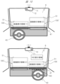
図14は、他の変形例として、車両の一部を構成する被投射部材として、車両1を構成するリアガラス6’を介して、例えば、車両の外部にいる歩行者等に対して情報を表示するものである。その結果、運転者や同乗者は、必要な情報を、上述したフロントガラス6上に監視することができるが(図9参照)、同時に、リアガラス6’によっても車外に情報を表示できる。なお、運転者や同乗者は、外部に対して表示した情報については、これを監視することはできず、そのため、運転者の視野を妨害することもない。即ち、車外への情報の表示によって車内の運転者や同乗者が外部の景観を監視することの妨げとはならない。
Figure 14 shows another modified example in which information is displayed to, for example, pedestrians outside the vehicle via the rear window 6' of the
この例では、図14(a)、図14(b)に示すように、車両の一部を構成する被投射部材であるリアガラス6’の下方に映像表示装置48を配置し、その映像光をリアガラス6’の全面または一部に設定した画像表示領域に向けて投射することにより、映像情報の表示を行う。
In this example, as shown in Figures 14(a) and 14(b), an
なお、この例でも、リアガラス6’の画像表示領域には上述した図13にも示した透明シート51’が設けられることは当然であろう。加えて、映像情報を車外へ向けて一方向に表示する被投射部材として、上述したフロントガラス6やリアガラス6’に限定されることはなく、その他、例えば、車両の側面を構成するサイドガラス6”(図1を参照)を利用することも可能であり、その場合、ここでは図示しないが、サイドガラス6”の近傍の部材(例えば、隣接する天井面や窓の枠組の一部など)に映像表示装置48を配置すると共に、サイドガラス6”の画像表示領域には、図13にも示した透明シート51’が設けられることは当然であろう。かかるサイドガラス6”への情報の表示は、例えば、タクシーにおいて、「お待たせしました」または「ご乗車ください」等のメッセージを路上の乗客等に対して表示するのに適しているであろう。
In this example, the image display area of the rear window 6' is naturally provided with the transparent sheet 51' shown in FIG. 13. In addition, the projected member that displays the image information in one direction toward the outside of the vehicle is not limited to the
加えて、以上に述べた例では、表示する映像情報を、車両を構成する被投射部材であるフロントガラス6やリアガラス6’やサイドガラス6”を介して、一方向に、車両の外部、または、内部に表示する車両情報表示装置100、100’、100”について述べた。しかしながら、本発明はこれらに限定されることなく、例えば、情報を車両の内部に表示する車両情報表示装置100と共に、情報を車両の外部に対して表示する車両情報表示装置100’を、適宜、組み合わせることも可能である。このことによれば、例えば、公共の交通機関であるバスや電車などに適用することによれば、そのリアガラス6’やサイドガラス6”を介して、車外の公衆に対して宣伝・広告や通知等を含む各種の情報を表示することが可能であり(但し、車内からは視認されない)、公衆への有効な情報の表示ができる。
In addition, in the above-mentioned examples, the vehicle
以上、種々の実施例について詳述したが、しかしながら、本発明は、上述した実施例のみに限定されるものではなく、様々な変形例が含まれる。例えば、上記した実施例は本発明を分かりやすく説明するためにシステム全体を詳細に説明したものであり、必ずしも説明した全ての構成を備えるものに限定されるものではない。また、ある実施例の構成の一部を他の実施例の構成に置き換えることが可能であり、また、ある実施例の構成に他の実施例の構成を加えることも可能である。また、各実施例の構成の一部について、他の構成の追加・削除・置換をすることが可能である。 Although various embodiments have been described above in detail, the present invention is not limited to the above-mentioned embodiments, and various modified examples are included. For example, the above-mentioned embodiments are detailed descriptions of the entire system in order to clearly explain the present invention, and are not necessarily limited to those having all of the configurations described. It is also possible to replace part of the configuration of one embodiment with the configuration of another embodiment, and it is also possible to add the configuration of another embodiment to the configuration of one embodiment. It is also possible to add, delete, or replace part of the configuration of each embodiment with other configurations.
1…自動車(車両)本体、6…フロントガラス、6’…リアガラス、6”…サイドガラス、100…車両情報表示装置、101…光源装置、48…映像表示装置(映像投射装置)、50…保護カバー、50a…膜またはフィルム、50b…波長板、51…透明シート(フィルム)、52…液晶表示パネル(映像表示素子)、54…光方向変換パネル、55…透明拡散シート材、56…基材、57…偏光板、58…位相差板、59…ブラックストライプ、300…スマートフォン。 1...Automobile (vehicle) body, 6...Front windshield, 6'...Rear windshield, 6"...Side windshield, 100...Vehicle information display device, 101...Light source device, 48...Image display device (image projection device), 50...Protective cover, 50a...Membrane or film, 50b...Wavelength plate, 51...Transparent sheet (film), 52...Liquid crystal display panel (image display element), 54...Light direction conversion panel, 55...Transparent diffusion sheet material, 56...Substrate, 57...Polarizing plate, 58...Retardation plate, 59...Black stripe, 300...Smartphone.
Claims (9)
映像光を出射する表示パネルと、
前記表示パネルから出射された映像光に含まれる特定の偏波を吸収する偏光板と、を備え、
前記表示パネルから出射され、前記特定の偏波が吸収された映像光を、車両のシールドガラスで反射させることで、前記表示パネルで生成した映像を虚像として前記車両の運転者へ向けて表示し、前記表示パネルから前記車両のシールドガラスの表示領域に向かって光束が進行するものであり、前記表示パネルからの光束の進行方向は前記車両の運転者から離れる方向に傾斜し、
前記シールドガラスの画像表示領域は自車両のボンネットが監視される範囲である、
表示装置。 A display device, comprising:
A display panel that emits image light;
a polarizing plate that absorbs a specific polarized wave contained in the image light emitted from the display panel;
The image light emitted from the display panel and having the specific polarized wave absorbed is reflected by a shield glass of the vehicle, thereby displaying the image generated by the display panel as a virtual image toward the driver of the vehicle, and a light beam travels from the display panel toward a display area of the shield glass of the vehicle, and the traveling direction of the light beam from the display panel is inclined in a direction away from the driver of the vehicle,
The image display area of the shield glass is a range in which the bonnet of the vehicle is monitored.
Display device.
前記車両の外部からの偏光波成分を吸収または反射する膜またはフィルムを有する保護カバーを備える、
表示装置。 2. The display device according to claim 1,
A protective cover having a membrane or film that absorbs or reflects polarized wave components from outside the vehicle is provided.
Display device.
前記保護カバーの前記膜または前記フィルムの光出射側に位相差板が配置されている、
表示装置。 3. The display device according to claim 2,
A retardation plate is disposed on the light emission side of the membrane or film of the protective cover.
Display device.
前記表示パネルの光出射面に設けられ、外光の表面反射を低減する保護カバーを備える、
表示装置。 2. The display device according to claim 1,
a protective cover provided on a light exit surface of the display panel to reduce surface reflection of external light;
Display device.
前記偏光板は、前記表示パネルと前記シールドガラスの間に配置されている、
表示装置。 2. The display device according to claim 1,
the polarizing plate is disposed between the display panel and the shield glass.
Display device.
前記表示パネルの入射側に第2の偏光板が配置されている、
表示装置。 2. The display device according to claim 1,
A second polarizing plate is disposed on the incident side of the display panel.
Display device.
前記表示パネルと前記シールドガラスの間にリニアフレネルレンズが配置されている、
表示装置。 2. The display device according to claim 1,
A linear Fresnel lens is disposed between the display panel and the shield glass.
Display device.
前記シールドガラスは、ウインドウガラスである、
表示装置。 2. The display device according to claim 1,
The shield glass is a window glass.
Display device.
前記シールドガラスは、リアガラスまたはサイドガラスである、
表示装置。 2. The display device according to claim 1,
The shield glass is a rear glass or a side glass.
Display device.
Priority Applications (2)
| Application Number | Priority Date | Filing Date | Title |
|---|---|---|---|
| JP2023204079A JP7667843B2 (en) | 2019-02-15 | 2023-12-01 | Display device |
| JP2025065699A JP2025100713A (en) | 2019-02-15 | 2025-04-11 | display device |
Applications Claiming Priority (3)
| Application Number | Priority Date | Filing Date | Title |
|---|---|---|---|
| JP2019025783A JP7117066B2 (en) | 2019-02-15 | 2019-02-15 | Vehicle information display device and vehicle information display system |
| JP2022121845A JP7397925B2 (en) | 2019-02-15 | 2022-07-29 | Vehicle information display device and vehicle information display system |
| JP2023204079A JP7667843B2 (en) | 2019-02-15 | 2023-12-01 | Display device |
Related Parent Applications (1)
| Application Number | Title | Priority Date | Filing Date |
|---|---|---|---|
| JP2022121845A Division JP7397925B2 (en) | 2019-02-15 | 2022-07-29 | Vehicle information display device and vehicle information display system |
Related Child Applications (1)
| Application Number | Title | Priority Date | Filing Date |
|---|---|---|---|
| JP2025065699A Division JP2025100713A (en) | 2019-02-15 | 2025-04-11 | display device |
Publications (2)
| Publication Number | Publication Date |
|---|---|
| JP2024025797A JP2024025797A (en) | 2024-02-26 |
| JP7667843B2 true JP7667843B2 (en) | 2025-04-23 |
Family
ID=72044488
Family Applications (4)
| Application Number | Title | Priority Date | Filing Date |
|---|---|---|---|
| JP2019025783A Active JP7117066B2 (en) | 2019-02-15 | 2019-02-15 | Vehicle information display device and vehicle information display system |
| JP2022121845A Active JP7397925B2 (en) | 2019-02-15 | 2022-07-29 | Vehicle information display device and vehicle information display system |
| JP2023204079A Active JP7667843B2 (en) | 2019-02-15 | 2023-12-01 | Display device |
| JP2025065699A Pending JP2025100713A (en) | 2019-02-15 | 2025-04-11 | display device |
Family Applications Before (2)
| Application Number | Title | Priority Date | Filing Date |
|---|---|---|---|
| JP2019025783A Active JP7117066B2 (en) | 2019-02-15 | 2019-02-15 | Vehicle information display device and vehicle information display system |
| JP2022121845A Active JP7397925B2 (en) | 2019-02-15 | 2022-07-29 | Vehicle information display device and vehicle information display system |
Family Applications After (1)
| Application Number | Title | Priority Date | Filing Date |
|---|---|---|---|
| JP2025065699A Pending JP2025100713A (en) | 2019-02-15 | 2025-04-11 | display device |
Country Status (4)
| Country | Link |
|---|---|
| US (2) | US12270993B2 (en) |
| JP (4) | JP7117066B2 (en) |
| CN (4) | CN117008341A (en) |
| WO (1) | WO2020166286A1 (en) |
Families Citing this family (17)
| Publication number | Priority date | Publication date | Assignee | Title |
|---|---|---|---|---|
| JP7059986B2 (en) * | 2019-07-18 | 2022-04-26 | 株式会社デンソー | Windshield display device |
| DE102019132252A1 (en) * | 2019-11-28 | 2021-06-02 | HELLA GmbH & Co. KGaA | Display device for a motor vehicle |
| KR20220062833A (en) * | 2020-11-09 | 2022-05-17 | 현대자동차주식회사 | Filming apparatus for vehicle |
| JP7545641B2 (en) * | 2020-11-30 | 2024-09-05 | 日本精機株式会社 | Display device |
| JP7631876B2 (en) * | 2021-02-22 | 2025-02-19 | 日本精機株式会社 | Passenger monitoring device and vehicle display device |
| EP4269153B1 (en) | 2021-03-02 | 2025-12-17 | Samsung Electronics Co., Ltd. | Electronic device for projecting image on windshield of vehicle, and operating method therefor |
| TWI772030B (en) * | 2021-05-20 | 2022-07-21 | 怡利電子工業股份有限公司 | Directional backlit type display |
| CN115373174B (en) * | 2021-05-20 | 2025-08-08 | 怡利电子工业股份有限公司 | Directional backlit display device |
| JP7715571B2 (en) * | 2021-08-19 | 2025-07-30 | 矢崎総業株式会社 | Vehicle display device |
| CN113960795B (en) * | 2021-09-18 | 2023-03-28 | 福耀玻璃工业集团股份有限公司 | Display window and vehicle |
| EP4163698B1 (en) * | 2021-10-08 | 2025-06-18 | Continental Automotive Technologies GmbH | Head-up display |
| JP7182830B1 (en) * | 2022-02-24 | 2022-12-05 | 株式会社Peco | Veterinary Medical Support System, Veterinary Medical Support Method and Program |
| JP7320094B1 (en) | 2022-03-01 | 2023-08-02 | ミネベアミツミ株式会社 | Planar lighting device |
| KR20240014266A (en) * | 2022-07-25 | 2024-02-01 | 현대모비스 주식회사 | Picture Generation Apparatus And Head-up Display Including Same |
| JP2025012233A (en) * | 2023-07-13 | 2025-01-24 | 矢崎総業株式会社 | Head-up display device |
| TWI888873B (en) * | 2023-07-20 | 2025-07-01 | 怡利電子工業股份有限公司 | Backlit display device with tapered reflective cup array |
| CN119247631A (en) * | 2024-11-15 | 2025-01-03 | 业成科技(成都)有限公司 | An anti-glare structure for an augmented reality head-up display cover |
Citations (12)
| Publication number | Priority date | Publication date | Assignee | Title |
|---|---|---|---|---|
| JP2000289488A (en) | 1999-04-08 | 2000-10-17 | Calsonic Kansei Corp | Display device for vehicle |
| WO2009072366A1 (en) | 2007-12-05 | 2009-06-11 | Bosch Corporation | Vehicle information display device |
| JP2014043205A (en) | 2012-08-28 | 2014-03-13 | Dainippon Printing Co Ltd | Image display system for vehicle |
| WO2015170406A1 (en) | 2014-05-09 | 2015-11-12 | 日立マクセル株式会社 | Head-up display device |
| JP2015225118A (en) | 2014-05-26 | 2015-12-14 | 株式会社デンソー | Head-up display device |
| DE202015003050U1 (en) | 2015-04-27 | 2016-08-01 | GM Global Technology Operations LLC (n. d. Ges. d. Staates Delaware) | Vehicle with head-up display |
| JP2017015778A (en) | 2015-06-26 | 2017-01-19 | 株式会社デンソー | Head-up display device |
| JP2017015918A (en) | 2015-06-30 | 2017-01-19 | パナソニックIpマネジメント株式会社 | Display device |
| JP2018072488A (en) | 2016-10-26 | 2018-05-10 | 日東電工株式会社 | Projection device, automobile and polarizing plate for projection device |
| DE102016124987A1 (en) | 2016-12-20 | 2018-06-21 | Dr. Ing. H.C. F. Porsche Aktiengesellschaft | Windshield and motor vehicle with a windshield |
| DE102017202566A1 (en) | 2017-02-17 | 2018-08-23 | Bayerische Motoren Werke Aktiengesellschaft | Arrangement for reflection suppression in a windscreen display device and windshield display device |
| US20180356634A1 (en) | 2016-02-18 | 2018-12-13 | Bayerische Motoren Werke Aktiengesellschaft | Projection Device for a Head-Up Display, Head-Up Display, and Vehicle |
Family Cites Families (32)
| Publication number | Priority date | Publication date | Assignee | Title |
|---|---|---|---|---|
| DE3822222A1 (en) | 1988-07-01 | 1990-01-04 | Bosch Gmbh Robert | DEVICE FOR HEAD-UP DISPLAYS ON MOTOR VEHICLES |
| JP2005084172A (en) * | 2003-09-05 | 2005-03-31 | Calsonic Kansei Corp | Display unit for vehicle |
| JP2005189725A (en) * | 2003-12-26 | 2005-07-14 | Denso Corp | Information display system for vehicle |
| US7355796B2 (en) | 2004-07-19 | 2008-04-08 | Colorlink, Inc. | Automobile windshield for HUD system |
| JP4670367B2 (en) | 2005-01-26 | 2011-04-13 | 株式会社デンソー | Display device |
| JP2009229552A (en) * | 2008-03-19 | 2009-10-08 | Fujinon Corp | Projection optical system and headup display device |
| JP2010079197A (en) | 2008-09-29 | 2010-04-08 | Fujifilm Corp | Anisotropic scattering film, film for head up display, and glass |
| KR20100070973A (en) | 2008-12-18 | 2010-06-28 | 박호철 | Head-up display navigation apparatus, system and service implementation method thereof |
| JP5699706B2 (en) | 2011-03-15 | 2015-04-15 | 住友電気工業株式会社 | In-vehicle display device |
| JP6027727B2 (en) * | 2011-09-09 | 2016-11-16 | 矢崎総業株式会社 | Vehicle display device |
| EP2618204A1 (en) * | 2012-01-20 | 2013-07-24 | Delphi Technologies, Inc. | Human machine interface for an automotive vehicle |
| JP2014197163A (en) | 2013-01-17 | 2014-10-16 | 株式会社ダイセル | Translucent diffusion type polarizing laminate and application of the same |
| JP6207850B2 (en) | 2013-03-13 | 2017-10-04 | 株式会社日立エルジーデータストレージ | Virtual image display device |
| JP2015118272A (en) * | 2013-12-18 | 2015-06-25 | 株式会社 オルタステクノロジー | Liquid crystal display device for head-up display device, and head-up display device |
| CN203688913U (en) * | 2014-01-15 | 2014-07-02 | 深圳市矽韦氏科技有限公司 | Anti-ghost head-up display device |
| JP2015194707A (en) | 2014-03-27 | 2015-11-05 | パナソニックIpマネジメント株式会社 | Display device |
| US9436007B2 (en) * | 2014-08-22 | 2016-09-06 | Hyundai Motor Company | Integrated cluster and head-up display device for vehicle |
| JP2016145956A (en) * | 2015-01-29 | 2016-08-12 | 株式会社東芝 | Optical device, head-mounted type image display apparatus including the same and imaging apparatus |
| JP2016155542A (en) * | 2015-02-20 | 2016-09-01 | 株式会社Jvcケンウッド | Vehicle display device |
| CN205427321U (en) | 2015-04-04 | 2016-08-03 | 孔晓辉 | Head raising displayer |
| EP3309611A4 (en) | 2015-06-15 | 2019-02-20 | JXTG Nippon Oil & Energy Corporation | TRANSPARENT SCREEN AND IMAGE PROJECTION SYSTEM COMPRISING SAME |
| JPWO2017073249A1 (en) | 2015-10-27 | 2018-08-16 | 株式会社小糸製作所 | Vehicle window display device |
| DE112016005483B4 (en) | 2015-12-01 | 2021-12-23 | Panasonic Intellectual Property Management Co., Ltd. | Head-Up Display |
| WO2017094550A1 (en) | 2015-12-02 | 2017-06-08 | Jxtgエネルギー株式会社 | Reflective transparent screen and image projection apparatus provided with same |
| JP2017151918A (en) | 2016-02-26 | 2017-08-31 | 沖電気工業株式会社 | Medium storing case, and automatic transacting device |
| WO2017175517A1 (en) * | 2016-04-05 | 2017-10-12 | 日立マクセル株式会社 | Light source apparatus and electronic apparatus employing same |
| CN115128814B (en) * | 2016-09-06 | 2023-09-15 | 麦克赛尔株式会社 | heads up display |
| JP2019003081A (en) | 2017-06-16 | 2019-01-10 | マクセル株式会社 | Light source device and head-up display device |
| DE102016225996A1 (en) * | 2016-12-22 | 2018-06-28 | Robert Bosch Gmbh | Projection display device and method for displaying a virtual image |
| DE102017206365A1 (en) | 2017-04-13 | 2018-10-18 | Bayerische Motoren Werke Aktiengesellschaft | Arrangement for reflection suppression in a windshield display device and a windshield display device |
| JP2020170113A (en) * | 2019-04-04 | 2020-10-15 | マクセル株式会社 | Information display system and vehicle information display system using it |
| JP7348750B2 (en) * | 2019-05-31 | 2023-09-21 | マクセル株式会社 | Information display system and vehicle information display system using it |
-
2019
- 2019-02-15 JP JP2019025783A patent/JP7117066B2/en active Active
-
2020
- 2020-01-22 CN CN202311054641.0A patent/CN117008341A/en active Pending
- 2020-01-22 CN CN202080007312.9A patent/CN113272714B/en active Active
- 2020-01-22 US US17/429,688 patent/US12270993B2/en active Active
- 2020-01-22 CN CN202311050300.6A patent/CN116990973A/en active Pending
- 2020-01-22 WO PCT/JP2020/002081 patent/WO2020166286A1/en not_active Ceased
- 2020-01-22 CN CN202311056166.0A patent/CN116890639A/en active Pending
-
2022
- 2022-07-29 JP JP2022121845A patent/JP7397925B2/en active Active
-
2023
- 2023-12-01 JP JP2023204079A patent/JP7667843B2/en active Active
-
2025
- 2025-02-26 US US19/063,435 patent/US20250199305A1/en active Pending
- 2025-04-11 JP JP2025065699A patent/JP2025100713A/en active Pending
Patent Citations (12)
| Publication number | Priority date | Publication date | Assignee | Title |
|---|---|---|---|---|
| JP2000289488A (en) | 1999-04-08 | 2000-10-17 | Calsonic Kansei Corp | Display device for vehicle |
| WO2009072366A1 (en) | 2007-12-05 | 2009-06-11 | Bosch Corporation | Vehicle information display device |
| JP2014043205A (en) | 2012-08-28 | 2014-03-13 | Dainippon Printing Co Ltd | Image display system for vehicle |
| WO2015170406A1 (en) | 2014-05-09 | 2015-11-12 | 日立マクセル株式会社 | Head-up display device |
| JP2015225118A (en) | 2014-05-26 | 2015-12-14 | 株式会社デンソー | Head-up display device |
| DE202015003050U1 (en) | 2015-04-27 | 2016-08-01 | GM Global Technology Operations LLC (n. d. Ges. d. Staates Delaware) | Vehicle with head-up display |
| JP2017015778A (en) | 2015-06-26 | 2017-01-19 | 株式会社デンソー | Head-up display device |
| JP2017015918A (en) | 2015-06-30 | 2017-01-19 | パナソニックIpマネジメント株式会社 | Display device |
| US20180356634A1 (en) | 2016-02-18 | 2018-12-13 | Bayerische Motoren Werke Aktiengesellschaft | Projection Device for a Head-Up Display, Head-Up Display, and Vehicle |
| JP2018072488A (en) | 2016-10-26 | 2018-05-10 | 日東電工株式会社 | Projection device, automobile and polarizing plate for projection device |
| DE102016124987A1 (en) | 2016-12-20 | 2018-06-21 | Dr. Ing. H.C. F. Porsche Aktiengesellschaft | Windshield and motor vehicle with a windshield |
| DE102017202566A1 (en) | 2017-02-17 | 2018-08-23 | Bayerische Motoren Werke Aktiengesellschaft | Arrangement for reflection suppression in a windscreen display device and windshield display device |
Also Published As
| Publication number | Publication date |
|---|---|
| US12270993B2 (en) | 2025-04-08 |
| JP7117066B2 (en) | 2022-08-12 |
| CN117008341A (en) | 2023-11-07 |
| JP2024025797A (en) | 2024-02-26 |
| JP2020134633A (en) | 2020-08-31 |
| CN113272714A (en) | 2021-08-17 |
| JP2025100713A (en) | 2025-07-03 |
| CN116990973A (en) | 2023-11-03 |
| JP2022145766A (en) | 2022-10-04 |
| US20250199305A1 (en) | 2025-06-19 |
| JP7397925B2 (en) | 2023-12-13 |
| CN113272714B (en) | 2023-09-08 |
| CN116890639A (en) | 2023-10-17 |
| US20220155589A1 (en) | 2022-05-19 |
| WO2020166286A1 (en) | 2020-08-20 |
Similar Documents
| Publication | Publication Date | Title |
|---|---|---|
| JP7667843B2 (en) | Display device | |
| JP7698097B2 (en) | information display device | |
| JP7587652B2 (en) | Display device | |
| US12601967B2 (en) | Information display system having acute-angled diffusion characteristics and image light control film used for the same | |
| WO2020203767A1 (en) | Information display system and vehicle information display system using this |
Legal Events
| Date | Code | Title | Description |
|---|---|---|---|
| A621 | Written request for application examination |
Free format text: JAPANESE INTERMEDIATE CODE: A621 Effective date: 20231201 |
|
| A977 | Report on retrieval |
Free format text: JAPANESE INTERMEDIATE CODE: A971007 Effective date: 20240614 |
|
| A131 | Notification of reasons for refusal |
Free format text: JAPANESE INTERMEDIATE CODE: A131 Effective date: 20240625 |
|
| A521 | Request for written amendment filed |
Free format text: JAPANESE INTERMEDIATE CODE: A523 Effective date: 20240809 |
|
| A131 | Notification of reasons for refusal |
Free format text: JAPANESE INTERMEDIATE CODE: A131 Effective date: 20241105 |
|
| A521 | Request for written amendment filed |
Free format text: JAPANESE INTERMEDIATE CODE: A523 Effective date: 20241218 |
|
| TRDD | Decision of grant or rejection written | ||
| A01 | Written decision to grant a patent or to grant a registration (utility model) |
Free format text: JAPANESE INTERMEDIATE CODE: A01 Effective date: 20250318 |
|
| A61 | First payment of annual fees (during grant procedure) |
Free format text: JAPANESE INTERMEDIATE CODE: A61 Effective date: 20250411 |
|
| R150 | Certificate of patent or registration of utility model |
Ref document number: 7667843 Country of ref document: JP Free format text: JAPANESE INTERMEDIATE CODE: R150 |