JP7665580B2 - Pressure Regulating Valve - Google Patents

Pressure Regulating Valve Download PDF

Info

Publication number
JP7665580B2
JP7665580B2 JP2022198886A JP2022198886A JP7665580B2 JP 7665580 B2 JP7665580 B2 JP 7665580B2 JP 2022198886 A JP2022198886 A JP 2022198886A JP 2022198886 A JP2022198886 A JP 2022198886A JP 7665580 B2 JP7665580 B2 JP 7665580B2
Authority
JP
Japan
Prior art keywords
pressure
valve
needle
diameter
regulating valve
Prior art date
Legal status (The legal status is an assumption and is not a legal conclusion. Google has not performed a legal analysis and makes no representation as to the accuracy of the status listed.)
Active
Application number
JP2022198886A
Other languages
Japanese (ja)
Other versions
JP2024084559A (en
Inventor
裕正 ▲高▼田
雄一郎 當山
Current Assignee (The listed assignees may be inaccurate. Google has not performed a legal analysis and makes no representation or warranty as to the accuracy of the list.)
Saginomiya Seisakusho Inc
Original Assignee
Saginomiya Seisakusho Inc
Priority date (The priority date is an assumption and is not a legal conclusion. Google has not performed a legal analysis and makes no representation as to the accuracy of the date listed.)
Filing date
Publication date
Application filed by Saginomiya Seisakusho Inc filed Critical Saginomiya Seisakusho Inc
Priority to JP2022198886A priority Critical patent/JP7665580B2/en
Priority to CN202311679664.0A priority patent/CN118188850A/en
Publication of JP2024084559A publication Critical patent/JP2024084559A/en
Application granted granted Critical
Publication of JP7665580B2 publication Critical patent/JP7665580B2/en
Active legal-status Critical Current
Anticipated expiration legal-status Critical

Links

Images

Classifications

    • FMECHANICAL ENGINEERING; LIGHTING; HEATING; WEAPONS; BLASTING
    • F16ENGINEERING ELEMENTS AND UNITS; GENERAL MEASURES FOR PRODUCING AND MAINTAINING EFFECTIVE FUNCTIONING OF MACHINES OR INSTALLATIONS; THERMAL INSULATION IN GENERAL
    • F16KVALVES; TAPS; COCKS; ACTUATING-FLOATS; DEVICES FOR VENTING OR AERATING
    • F16K17/00Safety valves; Equalising valves, e.g. pressure relief valves
    • F16K17/02Safety valves; Equalising valves, e.g. pressure relief valves opening on surplus pressure on one side; closing on insufficient pressure on one side
    • F16K17/04Safety valves; Equalising valves, e.g. pressure relief valves opening on surplus pressure on one side; closing on insufficient pressure on one side spring-loaded
    • F16K17/06Safety valves; Equalising valves, e.g. pressure relief valves opening on surplus pressure on one side; closing on insufficient pressure on one side spring-loaded with special arrangements for adjusting the opening pressure
    • FMECHANICAL ENGINEERING; LIGHTING; HEATING; WEAPONS; BLASTING
    • F16ENGINEERING ELEMENTS AND UNITS; GENERAL MEASURES FOR PRODUCING AND MAINTAINING EFFECTIVE FUNCTIONING OF MACHINES OR INSTALLATIONS; THERMAL INSULATION IN GENERAL
    • F16KVALVES; TAPS; COCKS; ACTUATING-FLOATS; DEVICES FOR VENTING OR AERATING
    • F16K1/00Lift valves or globe valves, i.e. cut-off apparatus with closure members having at least a component of their opening and closing motion perpendicular to the closing faces
    • F16K1/32Details
    • F16K1/34Cutting-off parts, e.g. valve members, seats
    • F16K1/36Valve members
    • F16K1/38Valve members of conical shape
    • F16K1/385Valve members of conical shape contacting in the closed position, over a substantial axial length, a seat surface having the same inclination
    • FMECHANICAL ENGINEERING; LIGHTING; HEATING; WEAPONS; BLASTING
    • F16ENGINEERING ELEMENTS AND UNITS; GENERAL MEASURES FOR PRODUCING AND MAINTAINING EFFECTIVE FUNCTIONING OF MACHINES OR INSTALLATIONS; THERMAL INSULATION IN GENERAL
    • F16KVALVES; TAPS; COCKS; ACTUATING-FLOATS; DEVICES FOR VENTING OR AERATING
    • F16K17/00Safety valves; Equalising valves, e.g. pressure relief valves
    • F16K17/02Safety valves; Equalising valves, e.g. pressure relief valves opening on surplus pressure on one side; closing on insufficient pressure on one side
    • F16K17/04Safety valves; Equalising valves, e.g. pressure relief valves opening on surplus pressure on one side; closing on insufficient pressure on one side spring-loaded
    • F16K17/0493Safety valves; Equalising valves, e.g. pressure relief valves opening on surplus pressure on one side; closing on insufficient pressure on one side spring-loaded with a spring other than a helicoidal spring
    • FMECHANICAL ENGINEERING; LIGHTING; HEATING; WEAPONS; BLASTING
    • F16ENGINEERING ELEMENTS AND UNITS; GENERAL MEASURES FOR PRODUCING AND MAINTAINING EFFECTIVE FUNCTIONING OF MACHINES OR INSTALLATIONS; THERMAL INSULATION IN GENERAL
    • F16KVALVES; TAPS; COCKS; ACTUATING-FLOATS; DEVICES FOR VENTING OR AERATING
    • F16K27/00Construction of housing; Use of materials therefor
    • F16K27/02Construction of housing; Use of materials therefor of lift valves
    • F16K27/0254Construction of housing; Use of materials therefor of lift valves with conical shaped valve members

Landscapes

  • Engineering & Computer Science (AREA)
  • General Engineering & Computer Science (AREA)
  • Mechanical Engineering (AREA)
  • Control Of Fluid Pressure (AREA)
  • Safety Valves (AREA)

Description

本発明は、調整ばね及び感圧部材を備える圧力調整弁に関する。 The present invention relates to a pressure regulating valve equipped with an adjustment spring and a pressure-sensitive member.

圧力調整弁において、調整ばね及び感圧部材を備えることにより、圧力変動に応じて、弁開度を制御することが行われてきた。 In pressure regulating valves, an adjustment spring and a pressure-sensitive member have been provided to control the valve opening in response to pressure fluctuations.

例えば、特許文献1には、図11(a)に示すように、圧力調整弁1100(以下、「従来の圧力調整弁」という)であって、弁座1118を有するバルブ本体1105と、弁座1118に対して離接可能な弁部1132を有するニードル1130と、軸線方向に弁部1132を付勢する、感圧用ベローズ1141を有する感圧ユニット1140と、弁部1132を弁閉方向に付勢する調整ばね1153を有する調整ばねユニット1150と、を備えるものが記載されている。 For example, as shown in FIG. 11(a), Patent Document 1 describes a pressure regulating valve 1100 (hereinafter referred to as a "conventional pressure regulating valve") that includes a valve body 1105 having a valve seat 1118, a needle 1130 having a valve portion 1132 that can be attached to and detached from the valve seat 1118, a pressure-sensing unit 1140 having a pressure-sensing bellows 1141 that biases the valve portion 1132 in the axial direction, and an adjustment spring unit 1150 having an adjustment spring 1153 that biases the valve portion 1132 in the valve closing direction.

特開2022-134450号公報JP 2022-134450 A

従来の圧力調整弁では、図11(b)に示すように、感圧用ベローズ1141の有効受圧面積S1’を、弁座1118に囲まれる弁部1132の受圧面積S2’に一致させることにより、感圧用ベローズ1141及び弁部1132のそれぞれに作用する二次側圧力P2の影響をキャンセルしていた。これにより、調節ばね1153の付勢力を調整することで、弁開圧力を設定して、一次側圧力の変動に応じた弁開度を制御している。 As shown in FIG. 11(b), in a conventional pressure regulating valve, the effective pressure receiving area S1' of the pressure sensing bellows 1141 is made to match the pressure receiving area S2' of the valve portion 1132 surrounded by the valve seat 1118, thereby canceling the effects of the secondary pressure P2 acting on the pressure sensing bellows 1141 and the valve portion 1132. This allows the valve opening pressure to be set by adjusting the biasing force of the adjustment spring 1153, thereby controlling the valve opening in response to fluctuations in the primary pressure.

しかしながら、感圧用ベローズ1141は、加工公差のばらつきが比較的大きい成形方法(ロール成形法、プレス成型法、液圧成形法など)により製造される。よって、感圧用ベローズ1141の有効受圧面積S1’のばらつきが大きく、有効受圧面積S1’を、弁座1118に囲まれる弁部1132の受圧面積S2’に一致させること、つまり、感圧用ベローズ1141の平均内径D1’を、弁ハウジング1110の弁ポート径D2’に一致させることは、極めて困難であった。 However, the pressure-sensitive bellows 1141 is manufactured by a molding method (roll forming, press molding, hydroforming, etc.) that has a relatively large variation in processing tolerances. Therefore, the effective pressure-receiving area S1' of the pressure-sensitive bellows 1141 varies widely, and it has been extremely difficult to match the effective pressure-receiving area S1' to the pressure-receiving area S2' of the valve section 1132 surrounded by the valve seat 1118, that is, to match the average inner diameter D1' of the pressure-sensitive bellows 1141 to the valve port diameter D2' of the valve housing 1110.

また、感圧用ベローズ1141の平均内径D1’を、弁ハウジング1110の弁ポート径D2’に一致させる際、既存の成形型を有する感圧用ベローズ(感圧用ベローズの平均内径が既知)の中から、所望の平均内径を有するものを選定しているが、感圧用ベローズ1141の平均内径D1’は、その成形方法より、最小径に限界があった。 In addition, when matching the average inner diameter D1' of the pressure-sensitive bellows 1141 to the valve port diameter D2' of the valve housing 1110, a pressure-sensitive bellows having the desired average inner diameter is selected from among pressure-sensitive bellows having existing molding dies (the average inner diameter of the pressure-sensitive bellows is known), but the average inner diameter D1' of the pressure-sensitive bellows 1141 has a minimum diameter limit due to the molding method.

したがって、例えば、従来の圧力調整弁において、小流量で用いられることが要求される場合であっても、感圧用ベローズ1141の平均内径D1’に弁ポート径D2’を一致させるために、弁ポート径D2’を大径化する必要があり、適用可能な流量制御範囲の下限値および設計の自由度に制約が生じていた。 Therefore, for example, even when a conventional pressure regulating valve is required to be used at a small flow rate, the valve port diameter D2' must be increased in order to match the average inner diameter D1' of the pressure-sensing bellows 1141, resulting in restrictions on the lower limit of the applicable flow control range and the degree of freedom in design.

以上より、従来の圧力調整弁では、感圧用ベローズ1141及び弁部1132のそれぞれに作用する二次側圧力P2の影響をキャンセルすることができず、二次側圧力P2の変動にともない、弁開圧力が著しく変化してしまうという問題(以下、「従来の問題点(二次側圧力による弁開圧力の変化)」という)が生じていた。 As a result of the above, with conventional pressure regulating valves, it was not possible to cancel the effects of the secondary pressure P2 acting on the pressure-sensing bellows 1141 and the valve portion 1132, and a problem arose in which the valve opening pressure changed significantly as the secondary pressure P2 varied (hereinafter referred to as "conventional problem (changes in valve opening pressure due to secondary pressure)").

本発明の目的は、感圧用ベローズの平均内径に代えて、ニードルシール部の外径を調整することにより、ニードルが加工公差を有する場合でも、二次側圧力による弁開圧力の変化を確実に抑制し得る圧力調整弁を提供することである。 The object of the present invention is to provide a pressure regulating valve that can reliably suppress changes in valve opening pressure caused by secondary pressure, even when the needle has processing tolerances, by adjusting the outer diameter of the needle seal portion instead of the average inner diameter of the pressure-sensitive bellows.

上記課題を解決するために、圧力調整弁は、弁ポートを有するバルブ本体と、前記弁ポートに対し、離接可能な弁部を有するニードルと、軸線方向に沿ってたわみ、前記弁部を付勢する感圧部材を有する感圧ユニットと、前記感圧ユニットを介して、前記弁部を弁閉方向に付勢する調整ばねを有する調整ばねユニットと、前記弁部が配置され、二次側圧力が導入される弁室と、前記ニードルの前記調整ばねユニット側に位置し、前記感圧部材を収容する背圧室と、前記背圧室に一次側圧力を導入するために、前記弁ポートと前記背圧室とを連通する圧力導入路と、前記ニードルのニードルシール部に設けられるとともに、前記背圧室と前記弁室とを区画するシール部材と、を備え、前記ニードルシール部の外径と弁ポート径とが略同一に形成される。 To solve the above problem, the pressure regulating valve includes a valve body having a valve port, a needle having a valve portion that can be attached to and detached from the valve port, a pressure-sensing unit having a pressure-sensing member that bends along the axial direction and urges the valve portion, an adjustment spring unit having an adjustment spring that urges the valve portion in a valve closing direction via the pressure-sensing unit, a valve chamber in which the valve portion is disposed and into which secondary pressure is introduced, a back pressure chamber located on the adjustment spring unit side of the needle and housing the pressure-sensing member, a pressure introduction passage that communicates the valve port and the back pressure chamber to introduce primary pressure into the back pressure chamber, and a seal member that is provided in the needle seal portion of the needle and that separates the back pressure chamber from the valve chamber, and the outer diameter of the needle seal portion and the valve port diameter are formed to be approximately the same.

また、上記圧力調整弁であって、前記圧力導入路は、前記バルブ本体に設けられるものとしてもよい。 In the above pressure regulating valve, the pressure introduction passage may be provided in the valve body.

また、上記圧力調整弁であって、前記一次側圧力を前記弁ポートに導入する一次側継手と、前記バルブ本体との間に継手コネクタを備え、前記バルブ本体及び前記継手コネクタの少なくとも一方には、前記圧力導入路に連通する連通凹部が形成されているものとしてもよい。 The pressure regulating valve may further include a coupling connector between the valve body and a primary coupling that introduces the primary pressure into the valve port, and at least one of the valve body and the coupling connector may have a communication recess that communicates with the pressure introduction passage.

また、上記圧力調整弁であって、前記一次側圧力を前記弁ポートに導入する一次側継手は、基部と、前記基部の内径より大きい内径を有し、前記圧力導入路に連通する接合部と、を備えるものとしてもよい。 In the pressure regulating valve, the primary side fitting that introduces the primary side pressure into the valve port may include a base and a joint that has an inner diameter larger than the inner diameter of the base and communicates with the pressure introduction passage.

また、上記圧力調整弁であって、前記ニードルシール部の外径は、前記弁ポート径よりも僅かに大きいものとしてもよい。 In the pressure regulating valve, the outer diameter of the needle seal portion may be slightly larger than the valve port diameter.

本発明によれば、感圧用ベローズの平均内径に代えて、ニードルシール部の外径を調整することにより、ニードルが加工公差を有する場合でも、二次側圧力による弁開圧力の変化を確実に抑制し得る圧力調整弁を提供することができる。 According to the present invention, by adjusting the outer diameter of the needle seal portion instead of the average inner diameter of the pressure-sensitive bellows, it is possible to provide a pressure regulating valve that can reliably suppress changes in valve opening pressure due to secondary pressure, even when the needle has processing tolerances.

本発明の第1の実施形態に係る圧力調整弁の弁閉状態を示す断面図である。1 is a cross-sectional view showing a pressure regulating valve according to a first embodiment of the present invention in a valve closed state. 図1の領域IIにおける部分拡大図である。FIG. 2 is a partially enlarged view of region II in FIG. 1 . 図2のニードルに作用する外力の説明図(ニードルシール部の外径≒弁ポート径の場合)であり、(a)は、ニードル全体図、(b)は、(a)に示されるニードルシール部及び弁部に作用する圧力の模式図を、それぞれ表す。3A and 3B are diagrams for explaining the external forces acting on the needle in FIG. 2 (when the outer diameter of the needle seal portion is approximately equal to the valve port diameter), in which (a) is an overall view of the needle, and (b) is a schematic diagram of the pressure acting on the needle seal portion and the valve portion shown in (a). 圧力調整弁における加工公差の影響を有する二次側圧力-弁開圧力特性図であり、(a)は、従来の圧力調整弁、(b)は、第1の実施形態の圧力調整弁を、それぞれ表す。5A and 5B are diagrams showing secondary pressure-valve opening pressure characteristics having the influence of processing tolerances in a pressure regulating valve, in which FIG. 5A shows a conventional pressure regulating valve, and FIG. 5B shows the pressure regulating valve of the first embodiment. 第1の実施形態の変形例に係る圧力調整弁におけるニードルに作用する外力の説明図(ニードルシール部の外径>弁ポート径の場合)であり、(a)は、ニードル全体図、(b)は、(a)に示されるニードルシール部及び弁部に作用する圧力の模式図を、それぞれ表す。1A and 1B are explanatory diagrams of external forces acting on a needle in a pressure regulating valve according to a modified example of the first embodiment (when the outer diameter of the needle seal portion is greater than the valve port diameter), in which (a) is an overall view of the needle, and (b) is a schematic diagram of pressures acting on the needle seal portion and the valve portion shown in (a). 図5に示す圧力調整弁における二次側圧力-弁開圧力特性図である。FIG. 6 is a characteristic diagram of secondary pressure vs. valve opening pressure in the pressure regulating valve shown in FIG. 第2の実施形態に係る圧力調整弁の弁閉状態を示す断面図である。FIG. 11 is a cross-sectional view showing a pressure regulating valve according to a second embodiment in a valve closed state. 図7の領域VIIIにおける部分拡大図である。FIG. 8 is a partial enlarged view of region VIII in FIG. 7 . 第3の実施形態に係る圧力調整弁の弁閉状態を示す断面図である。FIG. 11 is a cross-sectional view showing a pressure regulating valve according to a third embodiment in a valve closed state. 図9の領域Xにおける部分拡大図である。FIG. 10 is a partially enlarged view of a region X in FIG. 9 . 従来の圧力調整弁における弁閉状態を示す断面図であり、(a)は、全体図、(b)は、(a)の領域XIbにおける部分拡大図である。1A and 1B are cross-sectional views showing a conventional pressure regulating valve in a valve closed state, where FIG. 1A is an overall view, and FIG. 1B is a partially enlarged view of region XIb in FIG.

本発明の実施形態について、図1から図10を参照しながら詳細に説明する。ただし、本発明は本実施形態の態様に限定されるものではない。 An embodiment of the present invention will be described in detail with reference to Figures 1 to 10. However, the present invention is not limited to this embodiment.

<用語について>
本明細書および特許請求の範囲の記載において、「上」及び「下」とは、「調整ばねユニット側」及び「ニードル側」を示す。本明細書および特許請求の範囲の記載において、「一端」及び「他端」とは、「ニードル側」及び「調整ばねユニット側」を示す。本明細書および特許請求の範囲の記載において、「感圧用ベローズの有効受圧面積」とは、蛇腹形状の最小内径(感圧用ベローズの中心軸側に突出する蛇腹形状における「谷」部の内径)及び最大内径(感圧用ベローズの中心軸側の中心軸から離れる方向に突出する蛇腹形状の「山」部の内径)の平均内径に基づいて算出した近似値としての受圧面積を示す。本明細書および特許請求の範囲の記載において、「案内可能」とは、「摺動可能」を含むものを示す。本明細書および特許請求の範囲の記載において、「凹凸係合」とは、軸線方向へと窪む形状及び突出する形状がそれぞれ係合するものを示す。本明細書および特許請求の範囲の記載において、「ニードルシール部の外径と弁ポート径とが略同一」及び「ニードルシール部の外径は、弁ポート径よりも僅かに大きく」とは、弁ポート径に対するニードルシール部の外径の比をXとすると、「0.8<X<1.2の範囲に含まれるもの」及び「1<X<1.2の範囲に含まれるもの」を示す。
<Terminology>
In the present specification and claims, "upper" and "lower" refer to the "adjustment spring unit side" and "needle side". In the present specification and claims, "one end" and "other end" refer to the "needle side" and "adjustment spring unit side". In the present specification and claims, "effective pressure-receiving area of the pressure-sensing bellows" refers to the pressure-receiving area as an approximate value calculated based on the average inner diameter of the minimum inner diameter of the bellows shape (the inner diameter of the "valley" part of the bellows shape that protrudes toward the central axis of the pressure-sensing bellows) and the maximum inner diameter (the inner diameter of the "peak" part of the bellows shape that protrudes in a direction away from the central axis of the pressure-sensing bellows). In the present specification and claims, "guidable" refers to something that includes "slidable". In the present specification and claims, "convex-concave engagement" refers to engagement between a shape that is recessed in the axial direction and a shape that protrudes, respectively. In this specification and the claims, “the outer diameter of the needle seal portion and the valve port diameter are approximately the same” and “the outer diameter of the needle seal portion is slightly larger than the valve port diameter” mean “within the range of 0.8<X<1.2” and “within the range of 1<X<1.2”, where X is the ratio of the outer diameter of the needle seal portion to the valve port diameter.

(第1の実施形態)
<圧力調整弁の構成について>
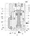
図1及び図2を用いて、本発明の第1の実施形態に係る圧力調整弁100Aについて説明する。圧力調整弁100Aは、バルブ本体5、ニードル(弁体)30、感圧ユニット40、調整ばねユニット50から主に構成される。以下、圧力調整弁100Aのそれぞれの構成に、下部接続手段60及び上部接続手段70を加えて順に説明する。なお、圧力調整弁100Aにおいて、ニードル30、感圧ユニット40、調整ばねユニット50の順に、一端側から他端側へと間接的に係合した状態で、バルブ本体5へと組付けられる。
(First embodiment)
<Configuration of the pressure regulating valve>
A pressure regulating valve 100A according to a first embodiment of the present invention will be described with reference to Figures 1 and 2. The pressure regulating valve 100A is mainly composed of a valve body 5, a needle (valve body) 30, a pressure sensitive unit 40, and an adjusting spring unit 50. Below, each component of the pressure regulating valve 100A will be described in order, along with a lower connecting means 60 and an upper connecting means 70. In the pressure regulating valve 100A, the needle 30, the pressure sensitive unit 40, and the adjusting spring unit 50 are assembled to the valve body 5 in this order, in a state in which they are indirectly engaged from one end side to the other end side.

ここで、詳細は後述するが、本実施形態の圧力調整弁100Aは、図3(b)に示すように、ニードルシール部34の受圧面積S4を、流量基準となる弁座部材18に囲まれる弁部32の受圧面積S2と略同一(つまり、ニードルシール部34の外径D4を、弁ポート径D2と略同一)になるように調整するものである。これにより、本実施形態の圧力調整弁100Aは、二次側圧力P2の影響を比較的簡単に抑制し、従来の問題点(二次側圧力による弁開圧力の変化)を解消することができる。 As will be described in detail later, the pressure regulating valve 100A of this embodiment adjusts the pressure receiving area S4 of the needle seal portion 34 to be approximately the same as the pressure receiving area S2 of the valve portion 32 surrounded by the valve seat member 18, which is the flow rate standard, as shown in FIG. 3(b) (i.e., the outer diameter D4 of the needle seal portion 34 is approximately the same as the valve port diameter D2). As a result, the pressure regulating valve 100A of this embodiment can relatively easily suppress the influence of the secondary pressure P2, and can solve the conventional problem (changes in valve opening pressure due to secondary pressure).

まず、バルブ本体5は、継手コネクタ3と、弁座部材18と、継手コネクタ3及び弁座部材18が固定される下バルブ本体10と、この下バルブ本体10の他端部にろう付けや溶接等により結合された上バルブ本体15と、この上バルブ本体15の他端部にかしめ等により結合されたばねケース20と、から構成される。このバルブ本体5は、真鍮、鉄、アルミニウム、ステンレス等の金属や、ポリフェニレンサルファイド(PPS)等の樹脂材料等、適宜な材質で構成される。 First, the valve body 5 is composed of the joint connector 3, the valve seat member 18, the lower valve body 10 to which the joint connector 3 and the valve seat member 18 are fixed, the upper valve body 15 which is joined to the other end of the lower valve body 10 by brazing, welding, etc., and the spring case 20 which is joined to the other end of the upper valve body 15 by crimping, etc. This valve body 5 is composed of an appropriate material such as metals such as brass, iron, aluminum, stainless steel, etc., or resin materials such as polyphenylene sulfide (PPS).

継手コネクタ3は、一端側に、流入管1(一次側継手)と接続する入口ポート11aを有するとともに、他端側に、円形形状に窪む連通凹部3aを有する。 The joint connector 3 has an inlet port 11a at one end that connects to the inlet pipe 1 (primary joint), and a circular recess 3a at the other end.

本実施形態において、継手コネクタ3と下バルブ本体10とを別部材とし、この継手コネクタ3に対して、簡単な機械加工で連通凹部3aを形成することにより、従前施されていた、下バルブ本体10への後述の圧力導入路としてのすり割り加工などを不要とし、加工時間を短縮できるとともに、形成された連通凹部3aを容易に視認することができる。 In this embodiment, the joint connector 3 and the lower valve body 10 are separate components, and the communication recess 3a is formed in the joint connector 3 by simple machining, eliminating the need for slotting to serve as a pressure introduction path to the lower valve body 10, as described below, which was previously required, shortening the processing time and allowing the formed communication recess 3a to be easily seen.

なお、本実施形態では、継手コネクタ3の連通凹部3aを、円形形状の窪みとするものであるが、これに限らず、例えば、直線形状の窪みなど、入口ポート11aと均圧路10aとを連通する形状であればよい。また、本実施形態では、継手コネクタ3に、入口ポート11aと均圧路10aとを連通する連通凹部3aを設けるものであるが、これに限らず、例えば、継手コネクタ3の連通凹部3aに代えて、下バルブ本体10の一端側に円形形状に窪む連通凹部10d(図8参照)を形成してもよいし、継手コネクタ3及び下バルブ本体10のそれぞれに、連通凹部3a及び連通凹部10dを形成してもよい。 In this embodiment, the communication recess 3a of the joint connector 3 is a circular recess, but the shape may be any shape that communicates between the inlet port 11a and the pressure equalizing path 10a, such as a linear recess. In this embodiment, the communication recess 3a that communicates between the inlet port 11a and the pressure equalizing path 10a is provided in the joint connector 3, but the shape may be any shape that communicates between the inlet port 11a and the pressure equalizing path 10a. In addition, the communication recess 3a of the joint connector 3 may be replaced by a communication recess 10d (see FIG. 8) that is circularly recessed on one end of the lower valve body 10, or the communication recess 3a and the communication recess 10d may be formed in each of the joint connector 3 and the lower valve body 10.

弁座部材18は、内部を貫通する弁ポート12を有し、弁室13と弁ポート12との接続部には、環状の弁座18aが設けられる。 The valve seat member 18 has a valve port 12 penetrating through it, and an annular valve seat 18a is provided at the connection between the valve chamber 13 and the valve port 12.

下バルブ本体10は、中心軸線Cに沿う貫通孔を有し、この貫通孔には、中心軸線Cに沿って、他端側から一端側へと階段状に順次拡径する複数の環状段部が形成される。この複数の環状段部には、他端側から一端側に向かって順に、ニードル案内孔14及び弁室13が画定されるとともに、連続する一端側の環状段部には、さらに、弁座部材18及び継手コネクタ3がそれぞれ挿入及びろう付けなどにより固定される。また、下バルブ本体10には、ニードル案内孔14の他端側に、ニードル案内孔14より内径が大きく設定されるシール収容溝10cが形成される。また、下バルブ本体10は、他端側の貫通孔の外周側に、弁ばね6の一端側を支持し、弁ばね6を収容する円筒形状のばね収容溝10bと、ばね収容溝10bに連通し、中心軸線Cと平行な方向に沿って延在する均圧路10a(圧力導入路)と、を備える。加えて、下バルブ本体10は、弁室13から半径方向へと貫通する貫通孔を有し、この貫通孔には、流出管2と接続する出口ポート11bが設けられる。 The lower valve body 10 has a through hole along the central axis C, and a plurality of annular steps are formed in the through hole, which are gradually enlarged in diameter from the other end side to the one end side along the central axis C. The needle guide hole 14 and the valve chamber 13 are defined in the plurality of annular steps from the other end side to the one end side, and the valve seat member 18 and the coupling connector 3 are fixed to the continuous annular step on the one end side by insertion and brazing, respectively. In addition, the lower valve body 10 has a seal housing groove 10c on the other end side of the needle guide hole 14, which has an inner diameter set larger than that of the needle guide hole 14. In addition, the lower valve body 10 has a cylindrical spring housing groove 10b on the outer periphery of the through hole on the other end side, which supports one end side of the valve spring 6 and houses the valve spring 6, and a pressure equalizing path 10a (pressure introduction path) which communicates with the spring housing groove 10b and extends along a direction parallel to the central axis C. In addition, the lower valve body 10 has a through hole that penetrates radially from the valve chamber 13, and this through hole is provided with an outlet port 11b that connects to the outflow pipe 2.

なお、本実施形態では、弁座部材18と下バルブ本体10とを別体とすることにより、比較的深い弁室13への中グリ加工を不要にするととともに、下バルブ本体10の出口ポート11bへのアクセスが容易となるため、バリ除去の作業効率を向上させることができる。 In this embodiment, the valve seat member 18 and the lower valve body 10 are separate, which eliminates the need for boring into the relatively deep valve chamber 13 and makes it easier to access the outlet port 11b of the lower valve body 10, improving the efficiency of burr removal.

上バルブ本体15は、中空円筒状の部材からなり、中心軸線Cに沿って、感圧ユニット40を収容する背圧室17を備える。 The upper valve body 15 is made of a hollow cylindrical member and has a back pressure chamber 17 along the central axis C that houses the pressure sensing unit 40.

この下バルブ本体10及び上バルブ本体15は、弁閉状態において、一次側圧力P1及び二次側圧力P2のそれぞれを導入する2つの圧力導入路を有する。 The lower valve body 10 and the upper valve body 15 have two pressure introduction paths that introduce the primary pressure P1 and the secondary pressure P2, respectively, when the valve is closed.

まず、第1の圧力導入路は、弁閉状態において、一次側圧力P1を入口ポート11aから背圧室17まで導入するものであり、連通凹部3a、均圧路10a、及び、ばね収容溝10bを介して連通する。なお、一次側圧力P1が導入される背圧室17は、シール収容溝10cと連通する。また、第1の圧力導入路中には、弁ばね6が介在するが、流路を完全に塞がないように配置されるため、背圧室17に一次側圧力P1を確実に導入することができる。 First, the first pressure introduction path introduces the primary pressure P1 from the inlet port 11a to the back pressure chamber 17 when the valve is closed, and communicates via the communication recess 3a, the pressure equalization path 10a, and the spring housing groove 10b. The back pressure chamber 17 to which the primary pressure P1 is introduced communicates with the seal housing groove 10c. In addition, the valve spring 6 is interposed in the first pressure introduction path, but is positioned so as not to completely block the flow path, so that the primary pressure P1 can be reliably introduced into the back pressure chamber 17.

また、第2の圧力導入路は、弁閉状態において、二次側圧力P2を出口ポート11bからシール収容溝10cまで導入するものであり、弁室13、及び、ニードル案内孔14とニードルガイド部31との間に形成される間隙を介して連通する。 The second pressure introduction path introduces the secondary pressure P2 from the outlet port 11b to the seal housing groove 10c when the valve is closed, and communicates with the valve chamber 13 via the gap formed between the needle guide hole 14 and the needle guide portion 31.

この2つの圧力導入路の他端側は、シール収容溝10cに配置されるシール部材7により、常時、非連通状態となるように区画される。これにより、弁閉状態において、背圧室17には、入口ポート11aを介して、一次側圧力P1を導入できるとともに、シール部材7の一端側に位置するシール収容溝10cには、出口ポート11bを介して、二次側圧力P2を導入できる。 The other end of these two pressure introduction paths is partitioned by the seal member 7 placed in the seal housing groove 10c so that they are always in a non-communicating state. As a result, when the valve is in a closed state, the primary side pressure P1 can be introduced into the back pressure chamber 17 via the inlet port 11a, and the secondary side pressure P2 can be introduced into the seal housing groove 10c located on one end side of the seal member 7 via the outlet port 11b.

このように、本実施形態では、圧力導入路となる均圧路10aが下バルブ本体10に形成されており、図11(a)に示される、従来の圧力調整弁1100のように、ニードル30に圧力導入路を設ける必要がないため、ニードル30及び弁ポート12の細径化を図ることができ、結果、圧力調整弁100Aを小型化及び小流量に対応させることができるとともに、ニードル30の形状の簡素化も図れる。 In this embodiment, the pressure equalization passage 10a, which serves as the pressure introduction passage, is formed in the lower valve body 10, and since there is no need to provide a pressure introduction passage in the needle 30 as in the conventional pressure regulating valve 1100 shown in FIG. 11(a), the diameter of the needle 30 and the valve port 12 can be made thinner. As a result, the pressure regulating valve 100A can be made smaller and adapted to small flow rates, and the shape of the needle 30 can also be simplified.

ばねケース20は、中心軸線Cに沿って貫通する貫通孔を有する中空円筒状の部材で、ばね収容室21が設けられる。また、ばねケース20の他端部の内周側には、雌ねじ部22が設けられ、調整ねじ部材52の外周側に設けられる雄ねじ部52aと、軸方向に移動可能に螺合される。この螺合部を介し、ばね収容室21には常時大気が導入される。 The spring case 20 is a hollow cylindrical member having a through hole that runs along the central axis C, and is provided with a spring accommodating chamber 21. A female threaded portion 22 is provided on the inner periphery of the other end of the spring case 20, and is screwed with a male threaded portion 52a provided on the outer periphery of the adjustment screw member 52 so as to be movable in the axial direction. Atmosphere is constantly introduced into the spring accommodating chamber 21 via this screwed portion.

次に、ニードル30について説明する。ニードル30は、ステンレス等の金属で構成され、一端側に設けられる略円錐台形状の弁部32と、他端側に設けられ、ステンレス鋼の薄板からなるばね支持部33と、弁部32とばね支持部33との間に設けられる円柱形状のニードルガイド部31と、シール収容溝10cと対向する位置に設けられるニードルシール部34と、を備える。このニードルシール部34は、ニードル30の一部を縮径させるものであり、ニードルシール部34の外径D4(図3(a)参照)は、ニードルガイド部31の外径D3(図3(a)参照)より小さく設定される。ここで、ニードルシール部34とシール収容溝10cとの隙間には、この隙間より、僅かに大きな半径方向厚みを有する環形状のシール部材7(例えば、Oリングなど)が配置される。これにより、シール部材7の内周面及び外周面は、常時、ニードルシール部34及びシール収容溝10cに、それぞれ接触するため、弁室13と背圧室17とを非連通状態で区画することができる。なお、シール部材7は、低摩擦性を有する材料(例えば、フッ素ゴムなど)からなるため、シール部材7に対するニードル30の摩擦抵抗を、極めて小さくすることができる。 Next, the needle 30 will be described. The needle 30 is made of a metal such as stainless steel, and includes a valve portion 32 having a generally truncated cone shape provided at one end, a spring support portion 33 made of a thin plate of stainless steel provided at the other end, a cylindrical needle guide portion 31 provided between the valve portion 32 and the spring support portion 33, and a needle seal portion 34 provided at a position facing the seal housing groove 10c. This needle seal portion 34 reduces the diameter of a part of the needle 30, and the outer diameter D4 (see FIG. 3(a)) of the needle seal portion 34 is set smaller than the outer diameter D3 (see FIG. 3(a)) of the needle guide portion 31. Here, a ring-shaped seal member 7 (e.g., an O-ring) having a radial thickness slightly larger than this gap is disposed in the gap between the needle seal portion 34 and the seal housing groove 10c. As a result, the inner and outer circumferential surfaces of the seal member 7 are always in contact with the needle seal portion 34 and the seal housing groove 10c, respectively, so the valve chamber 13 and the back pressure chamber 17 can be partitioned in a non-communicating state. In addition, because the seal member 7 is made of a material with low friction (such as fluororubber), the frictional resistance of the needle 30 against the seal member 7 can be made extremely small.

本実施形態におけるシール部材7の保持手段は、下バルブ本体10に、シール部材7を収容するシール収容溝10cを設けるものであるが、これに限らず、例えば、ニードル30に、シール部材7を収容するシール収容溝を設けるものや、下バルブ本体10及びニードル30の両方に、シール部材7を収容するシール収容溝を設けるものであってもよい。 In this embodiment, the means for holding the seal member 7 is a seal housing groove 10c that houses the seal member 7 in the lower valve body 10, but is not limited to this. For example, the needle 30 may be provided with a seal housing groove that houses the seal member 7, or both the lower valve body 10 and the needle 30 may be provided with seal housing grooves that house the seal member 7.

ニードルガイド部31が、下バルブ本体10のニードル案内孔14内を軸方向に案内可能に配置される。ここで、ニードルガイド部31の外径D3とニードル案内孔14の内径との間に形成される間隙は、比較的小さくなるように設定されており、厳密な加工公差の管理が行われている。また、ニードル30は、ニードル30のばね支持部33と下バルブ本体10のばね収容溝10bの底面との間に挟持された弁ばね6により、常時、弁開方向へと付勢される。このように、ニードル30は、軸方向に安定した状態でガイドされており、中心軸線C方向からみた、ニードル30と弁座18aとの中心位置は常に一致するため、流量の安定化及び弁漏れ性を向上させることができる。 The needle guide portion 31 is arranged so as to be guided in the axial direction within the needle guide hole 14 of the lower valve body 10. Here, the gap formed between the outer diameter D3 of the needle guide portion 31 and the inner diameter of the needle guide hole 14 is set to be relatively small, and strict processing tolerances are managed. In addition, the needle 30 is constantly biased in the valve opening direction by the valve spring 6 sandwiched between the spring support portion 33 of the needle 30 and the bottom surface of the spring accommodation groove 10b of the lower valve body 10. In this way, the needle 30 is guided in a stable axial direction, and the central positions of the needle 30 and the valve seat 18a as viewed from the direction of the central axis C always coincide, so that the flow rate can be stabilized and the valve leakage can be improved.

ニードル30の軸方向への移動については、詳細は後述するが、一次側圧力P1と二次側圧力P2との圧力差や、弁部32の他端部に作用する感圧用ベローズ41及び調整ばね53の付勢力や、ばね支持部33に作用する弁ばね6の付勢力などにより生じる。これらの外力により、弁部32が弁座18aに対して離接可能に移動し、弁開度が決まる。ここで、連結棒45の段差部45cがベローズ上蓋43と当接することにより、ニードル30の弁閉状態から最大弁リフト状態となる弁全開状態までの最大弁リフト量が規定される。なお、本実施形態の圧力調整弁100Aにおいては、最大弁リフト状態となる弁全開状態とは別に、連結棒45の段差部45cがベローズ上蓋43と当接する手前に、規定の流量が流れる弁開量の状態となる弁全開状態がある。 The axial movement of the needle 30 is caused by the pressure difference between the primary pressure P1 and the secondary pressure P2, the biasing force of the pressure-sensitive bellows 41 and the adjustment spring 53 acting on the other end of the valve portion 32, and the biasing force of the valve spring 6 acting on the spring support portion 33, as described in detail below. These external forces cause the valve portion 32 to move toward and away from the valve seat 18a, and the valve opening degree is determined. Here, the step portion 45c of the connecting rod 45 abuts against the bellows top cover 43, thereby defining the maximum valve lift amount from the valve closed state of the needle 30 to the valve fully open state, which is the maximum valve lift state. In addition to the valve fully open state, which is the maximum valve lift state, in the pressure regulating valve 100A of this embodiment, there is a valve fully open state in which a specified flow rate flows before the step portion 45c of the connecting rod 45 abuts against the bellows top cover 43.

続いて、感圧ユニット40について説明する。感圧ユニット40は、感圧用ベローズ(感圧部材)41と、ベローズ上蓋43と、中心軸線Cに沿って延在する一端部及び他端部を有する連結棒45と、から構成される。この感圧用ベローズ41は、中心軸線Cに沿って延在する一端部及び他端部を、連結棒45の一端部及びベローズ上蓋43にそれぞれ接続させるとともに、弁部32を弁閉方向に付勢する。感圧ユニット40は、ステンレス等の金属で構成されており、上バルブ本体15の背圧室17内に収容される。なお、本実施形態では、感圧用ベローズ41が自由長に対して縮めた状態で、背圧室17内に組み込むことにより、感圧用ベローズ41が弁部32を弁閉方向に付勢するものである。しかしながら、これに限らず、感圧用ベローズ41を自由長に対して伸ばした状態で、背圧室17内に組み込むことにより、感圧用ベローズ41が弁部32を弁開方向に付勢するものであってもよい。 Next, the pressure-sensing unit 40 will be described. The pressure-sensing unit 40 is composed of a pressure-sensing bellows (pressure-sensing member) 41, a bellows top cover 43, and a connecting rod 45 having one end and the other end extending along the central axis C. The pressure-sensing bellows 41 has one end and the other end extending along the central axis C connected to one end of the connecting rod 45 and the bellows top cover 43, respectively, and biases the valve portion 32 in the valve closing direction. The pressure-sensing unit 40 is made of a metal such as stainless steel, and is housed in the back pressure chamber 17 of the upper valve body 15. In this embodiment, the pressure-sensing bellows 41 is incorporated into the back pressure chamber 17 in a state in which it is contracted relative to its free length, and the pressure-sensing bellows 41 biases the valve portion 32 in the valve closing direction. However, this is not limiting, and the pressure-sensing bellows 41 may be inserted into the back pressure chamber 17 in a state in which the pressure-sensing bellows 41 is stretched relative to its free length, so that the pressure-sensing bellows 41 biases the valve portion 32 in the valve opening direction.

感圧用ベローズ41は、連結棒45の一端部及びベローズ上蓋43のそれぞれと接続されることにより、感圧用ベローズ41の外部空間には、入口ポート11a、連通凹部3a、均圧路10a、ばね収容溝10b、及び、背圧室17を介して、常時、一次側圧力P1が導入される。一方、感圧用ベローズ41の内部空間には、連結棒45の小径部45bとベローズ上蓋43の挿通孔43aとの間に形成された間隙、及び、上ボール73とベローズ上蓋43の摺動部43cとの間に形成された間隙を介して、常時大気が導入される。また、この感圧用ベローズ41において、蛇腹形状の山部の外径及び谷部の内径は、上バルブ本体15及び連結棒45のそれぞれと、常時、非接触状態となるように各部の寸法関係が設定される。 The pressure-sensing bellows 41 is connected to one end of the connecting rod 45 and the bellows top cover 43, so that the primary pressure P1 is constantly introduced into the external space of the pressure-sensing bellows 41 through the inlet port 11a, the communicating recess 3a, the pressure equalizing passage 10a, the spring accommodation groove 10b, and the back pressure chamber 17. On the other hand, the atmosphere is constantly introduced into the internal space of the pressure-sensing bellows 41 through the gap formed between the small diameter portion 45b of the connecting rod 45 and the insertion hole 43a of the bellows top cover 43, and the gap formed between the upper ball 73 and the sliding portion 43c of the bellows top cover 43. In addition, the dimensional relationship of each part is set so that the outer diameter of the peaks and the inner diameter of the valleys of the bellows shape are always in a non-contact state with the upper valve body 15 and the connecting rod 45.

連結棒45は、軸方向の一端側へ延在する略円柱形状の大径部45aと、大径部45aから軸方向の他端側へ延在する略円柱形状の小径部45bと、を備える。大径部45aの一端部には、径方向へと突出するとともに、感圧用ベローズ41の一端部が接続されるフランジ部45dが形成される。また、大径部45aと小径部45bとの間には、環状の段差部45cが形成される。 The connecting rod 45 has a generally cylindrical large diameter portion 45a extending toward one end in the axial direction, and a generally cylindrical small diameter portion 45b extending from the large diameter portion 45a toward the other end in the axial direction. One end of the large diameter portion 45a is formed with a flange portion 45d that protrudes in the radial direction and to which one end of the pressure-sensing bellows 41 is connected. In addition, an annular step portion 45c is formed between the large diameter portion 45a and the small diameter portion 45b.

ベローズ上蓋43は、中心軸線Cに沿って同心上に延在し、連結棒45の小径部45bが挿通する挿通孔43aと、感圧用ベローズ41の他端部が接続されるベローズ上蓋接合部43bと、中心軸線Cに沿って同心上に延在し、挿通孔43aより内径が大きく設定されるとともに、連結棒45の小径部45bが挿通し、上ボール73が摺動する円筒形状の摺動部43cと、を備える。ここで、感圧ユニット40は、バルブ本体5に対して、溶接部wを介して、相対変位不能に固定される。この溶接部wは、ベローズ上蓋43及び上バルブ本体15の他端部同士を、互いに溶接した領域を示す。この溶接部wの軸方向の位置を調整することにより、感圧ユニット40の長さの個体差や、バルブ本体5への組付け誤差などを吸収することができる。 The bellows top cover 43 extends concentrically along the central axis C and includes an insertion hole 43a through which the small diameter portion 45b of the connecting rod 45 passes, a bellows top cover joint 43b to which the other end of the pressure-sensing bellows 41 is connected, and a cylindrical sliding portion 43c that extends concentrically along the central axis C and has an inner diameter larger than that of the insertion hole 43a, through which the small diameter portion 45b of the connecting rod 45 passes and through which the upper ball 73 slides. Here, the pressure-sensing unit 40 is fixed to the valve body 5 via a welded portion w so that it cannot be displaced relative to the valve body 5. This welded portion w indicates the area where the other ends of the bellows top cover 43 and the upper valve body 15 are welded to each other. By adjusting the axial position of this welded portion w, individual differences in the length of the pressure-sensing unit 40 and assembly errors to the valve body 5 can be absorbed.

本実施形態において、感圧ユニット40の一端側は、感圧用ベローズ41と連結棒45のフランジ部45dとを接続した構成となっているが、これに限らない。例えば、有蓋形状の下端部を有する感圧用ベローズ41、または、連結棒45の一端部からフランジ部45dを分離した様態のベローズ下蓋を採用し、連結棒45からフランジ部45dを省略するとともに、この有蓋形状の下端部またはベローズ下蓋に、連結棒45の一端部を接続した構成としてもよい。なお、連結棒45の一端部を、有蓋形状の下端部またはベローズ下蓋に対して、半径方向に移動可能な接続形態とすることにより、連結棒45の中心軸線Cに対する傾きや、感圧用ベローズ41の非対称性などを吸収することができる。 In this embodiment, one end of the pressure-sensing unit 40 is configured to connect the pressure-sensing bellows 41 and the flange portion 45d of the connecting rod 45, but this is not limited to the above. For example, a pressure-sensing bellows 41 having a capped lower end or a bellows lower cover in which the flange portion 45d is separated from one end of the connecting rod 45 may be used, and the flange portion 45d may be omitted from the connecting rod 45, with one end of the connecting rod 45 being connected to the capped lower end or the bellows lower cover. By connecting one end of the connecting rod 45 in a manner that allows it to move radially relative to the capped lower end or the bellows lower cover, it is possible to absorb the inclination of the connecting rod 45 with respect to the central axis C and the asymmetry of the pressure-sensing bellows 41.

本実施形態において、感圧ユニット40の他端側は、感圧用ベローズ41とベローズ上蓋43とを接続した構成となっているが、これに限らない。例えば、フランジ形状の上端部を有する感圧用ベローズ41を採用し、ベローズ上蓋43を省略するとともに、感圧用ベローズ41の上端部における外縁を、バルブ本体5である上バルブ本体15の内壁に相対変位不能に固定し、上バルブ本体15をベローズ上蓋43として用いた構成でもよい。このように、感圧用ベローズ41の上端部を、上バルブ本体15の内壁に固定した場合は、ベローズ上蓋43の挿通孔43a及び摺動部43cは、上バルブ本体15の内壁に形成される。 In this embodiment, the other end side of the pressure sensing unit 40 is configured by connecting the pressure sensing bellows 41 and the bellows top cover 43, but this is not limited to the above. For example, a pressure sensing bellows 41 having a flange-shaped upper end may be used, the bellows top cover 43 may be omitted, and the outer edge of the upper end of the pressure sensing bellows 41 may be fixed to the inner wall of the upper valve body 15, which is the valve body 5, so that it cannot be displaced relative to the pressure sensing bellows 41, and the upper valve body 15 may be used as the bellows top cover 43. In this way, when the upper end of the pressure sensing bellows 41 is fixed to the inner wall of the upper valve body 15, the insertion hole 43a and the sliding portion 43c of the bellows top cover 43 are formed in the inner wall of the upper valve body 15.

さらに、下部接続手段60について説明する。この下部接続手段60は、ニードル30及び感圧ユニット40における軸方向対向面に形成される一対の窪み部61,62と、この一対の窪み部61,62の間に、凹凸係合を形成するように挟持される下ボール63と、から構成される。この一対の窪み部61,62は、ニードル30の上端面及び大径部45aの下端面における軸心部に形成されており、円錐形状の下側窪み部61及び上側窪み部62から構成される。この円錐形状は、中心軸線Cと同心円に形成された底面と、中心軸線C上に位置する頂点とを有している。また、下ボール63は、ステンレス等の金属で構成される。 The lower connection means 60 will now be described. The lower connection means 60 is composed of a pair of recesses 61, 62 formed on the axially opposing surfaces of the needle 30 and the pressure-sensing unit 40, and a lower ball 63 that is sandwiched between the pair of recesses 61, 62 to form a concave-convex engagement. The pair of recesses 61, 62 are formed at the axial center of the upper end surface of the needle 30 and the lower end surface of the large diameter portion 45a, and are composed of a conical lower recess 61 and upper recess 62. The conical shape has a bottom surface formed concentrically with the central axis C, and an apex located on the central axis C. The lower ball 63 is composed of a metal such as stainless steel.

これにより、ニードル30は、下バルブ本体10のニードル案内孔14内に、中心軸線Cに沿って案内可能に配置されるため、下側窪み部61の中心位置は、常時、中心軸線C上に位置している。また、上側窪み部62の中心位置は、下側窪み部61及び下ボール63を介して、上側窪み部62に求心作用が働くため、中心軸線C上に自立的に配置される。これにより、感圧用ベローズ41の非対称性などに起因した、中心軸線Cに沿わない付勢力が、ニードル30に伝達されることを抑制し、ニードル30の摺動抵抗を減少させることができる。なお、本実施形態において、下側窪み部61、上側窪み部62は、それぞれ円錐形状を有するものであるが、これに限らず、例えば、球面形状を有するものであってもよい。 As a result, the needle 30 is arranged in the needle guide hole 14 of the lower valve body 10 so as to be guided along the central axis C, and the center position of the lower recess 61 is always located on the central axis C. In addition, the center position of the upper recess 62 is independently located on the central axis C because a centripetal force acts on the upper recess 62 via the lower recess 61 and the lower ball 63. This makes it possible to suppress the transmission of a biasing force that is not along the central axis C, due to the asymmetry of the pressure-sensing bellows 41, to the needle 30, thereby reducing the sliding resistance of the needle 30. In this embodiment, the lower recess 61 and the upper recess 62 each have a conical shape, but are not limited to this and may have a spherical shape, for example.

加えて、調整ばねユニット50について説明する。調整ばねユニット50は、ばね受け部材51と、調整ねじ部材52と、ばね受け部材51及び調整ねじ部材52の間に挟持され、弁部32を弁閉方向に付勢する調整ばね53と、から構成される。ばね受け部材51及び調整ねじ部材52は、真鍮、鉄、アルミニウム、ステンレス等の金属や、ポリフェニレンサルファイド(PPS)等の樹脂材料等、適宜な材質で構成されており、ばねケース20のばね収容室21内に収容される。この調整ねじ部材52の外周側に設けられる雄ねじ部52aと、ばねケース20の他端部の内周側に設けられる雌ねじ部22とを螺合させ、調整ねじ部材52を軸方向に移動させることにより、調整ばね53の付勢力を調整し、ニードル30が弁開する圧力(設定値)を調整することができる。 In addition, the adjustment spring unit 50 will be described. The adjustment spring unit 50 is composed of a spring receiving member 51, an adjustment screw member 52, and an adjustment spring 53 that is sandwiched between the spring receiving member 51 and the adjustment screw member 52 and biases the valve portion 32 in the valve closing direction. The spring receiving member 51 and the adjustment screw member 52 are made of appropriate materials such as metals such as brass, iron, aluminum, and stainless steel, and resin materials such as polyphenylene sulfide (PPS), and are housed in the spring housing chamber 21 of the spring case 20. By screwing the male threaded portion 52a provided on the outer periphery of the adjustment screw member 52 with the female threaded portion 22 provided on the inner periphery of the other end of the spring case 20, and moving the adjustment screw member 52 in the axial direction, the biasing force of the adjustment spring 53 can be adjusted, and the pressure (set value) at which the needle 30 opens the valve can be adjusted.

調整ばね53は、多重巻型ウェーブスプリング(以下、「ウェーブスプリング」という)であり、ステンレス等の金属で構成される。このウェーブスプリングは、断面形状が矩形状の線材を、正弦波形状に所定のピッチで褶曲させ、ばね中心軸方向に対向する山部及び谷部を互いに接触及び離間させる接触部及び離間部が巻回方向に交互に形成され、全体として円筒形状に形成される。よって、ウェーブスプリングが圧縮される際に、複数の接触部が常時支点となるため、サイドフォースを抑制し、中心軸線Cに沿って付勢力を確実に伝達することができる。 The adjustment spring 53 is a multi-wound wave spring (hereinafter referred to as a "wave spring") made of a metal such as stainless steel. This wave spring is made by bending a wire rod with a rectangular cross section into a sinusoidal waveform at a specified pitch, and contact and separation parts that bring the peaks and valleys facing each other in the direction of the spring's central axis into contact with and separate from each other are formed alternately in the winding direction, resulting in a cylindrical shape overall. Therefore, when the wave spring is compressed, the multiple contact parts always serve as fulcrums, suppressing side forces and ensuring the transmission of biasing force along the central axis C.

最後に、上部接続手段70について説明する。上部接続手段70は、連結棒45及びばね受け部材51における軸方向対向面に形成される一対の係合部71,72と、この一対の係合部71,72の間に、凹凸係合を形成するように挟持され、球形状を有する上ボール73と、から構成される。この一対の係合部71,72は、小径部45bの上端面及びばね受け部材51の下端面における軸心部に形成されており、円錐形状の下側係合部71及び上側係合部72から構成される。この円錐形状は、中心軸線Cと同心円に形成された底面と、中心軸線C上に位置する頂点とを有している。また、上ボール73は、ステンレス等の金属で構成される。 Finally, the upper connection means 70 will be described. The upper connection means 70 is composed of a pair of engagement parts 71, 72 formed on the axially opposing surfaces of the connecting rod 45 and the spring receiving member 51, and a spherical upper ball 73 that is sandwiched between the pair of engagement parts 71, 72 to form a concave-convex engagement. The pair of engagement parts 71, 72 are formed on the axial center of the upper end surface of the small diameter part 45b and the lower end surface of the spring receiving member 51, and are composed of a conical lower engagement part 71 and an upper engagement part 72. This conical shape has a bottom surface formed concentrically with the central axis C, and an apex located on the central axis C. The upper ball 73 is also composed of a metal such as stainless steel.

ここで、中心軸線C方向からみて、上ボール73における円形状の側部の半径は、摺動部43cの半径より僅かに小さく設定されているため、上ボール73の側部と、摺動部43cとの間には、極めて狭い間隙が形成されている。よって、上ボール73の側部は、摺動部43cと、常に点接触状態になり、半径方向への移動を規制されるため、上ボール73の中心位置は、常時、中心軸線C上近傍に配置される。また、下側係合部71及び上側係合部72の中心位置は、半径方向への移動が規制されている上ボール73を介して、下側係合部71及び上側係合部72にそれぞれ求心作用が働くため、中心軸線C上近傍に自立的に配置される。さらに、連結棒45の小径部45bは、挿通孔43aに対して、非接触状態で、中心軸線Cに沿って挿通されるように設定されている。このように、上部接続手段70は、連結棒45が中心軸線Cに対して傾くことを抑制するとともに、摺動部43cとの摺動抵抗を減少させ、ヒステリシスを低減させることができる。 Here, as viewed from the direction of the central axis C, the radius of the circular side of the upper ball 73 is set slightly smaller than the radius of the sliding part 43c, so that an extremely narrow gap is formed between the side of the upper ball 73 and the sliding part 43c. Therefore, the side of the upper ball 73 is always in point contact with the sliding part 43c, and the radial movement is restricted, so that the center position of the upper ball 73 is always located near the central axis C. In addition, the center positions of the lower engaging part 71 and the upper engaging part 72 are independently located near the central axis C because a centripetal force acts on the lower engaging part 71 and the upper engaging part 72 via the upper ball 73, whose radial movement is restricted. Furthermore, the small diameter part 45b of the connecting rod 45 is set to be inserted along the central axis C in a non-contact state with the insertion hole 43a. In this way, the upper connection means 70 prevents the connecting rod 45 from tilting relative to the central axis C, and reduces the sliding resistance with the sliding part 43c, thereby reducing hysteresis.

<圧力調整弁の動作について>
圧力調整弁100Aの動作について説明する。ここで、圧力調整弁100Aが用いられる対象を冷媒回路として説明するが、これに限らない。圧力調整弁100Aにおいて、入口ポート11aは、高圧(一次側圧力P1)側の流入管1と接続され、出口ポート11bは、低圧(二次側圧力P2)側の流出管2と接続される。
<Operation of the pressure regulating valve>
The operation of the pressure regulating valve 100A will be described. Here, the pressure regulating valve 100A is described as being used in a refrigerant circuit, but is not limited to this. In the pressure regulating valve 100A, the inlet port 11a is connected to an inlet pipe 1 on the high pressure (primary pressure P1) side, and the outlet port 11b is connected to an outlet pipe 2 on the low pressure (secondary pressure P2) side.

(一次側圧力P1が設定値(弁開圧力)よりも低い場合)
一次側圧力P1が設定値よりも低い場合(例えば、圧縮機の吐出圧力が低下した状態など)には、図2に示すように、弁部32が弁座18aに着座しており、弁閉状態となっている。その際、一次側圧力P1は、入口ポート11a、連通凹部3a、均圧路10a、及び、ばね収容溝10bを介して、背圧室17である感圧用ベローズ41の外部空間に導入される。
(When the primary pressure P1 is lower than the set value (valve opening pressure))
When the primary pressure P1 is lower than the set value (for example, when the discharge pressure of the compressor is reduced), the valve portion 32 is seated on the valve seat 18a and the valve is closed as shown in Fig. 2. At that time, the primary pressure P1 is introduced into the external space of the pressure-sensing bellows 41, which is the back pressure chamber 17, via the inlet port 11a, the communication recess 3a, the pressure equalizing passage 10a, and the spring accommodating groove 10b.

まず、感圧用ベローズ41には、弁部32が弁開する方向に作用する力として、一次側圧力P1×有効受圧面積S1(図2参照)が生じている。ここで、感圧用ベローズ41の有効受圧面積S1とは、蛇腹形状の最小内径及び最大内径の平均内径に基づいて算出した受圧面積である。 First, the pressure-sensing bellows 41 generates a force acting in the direction in which the valve portion 32 opens, which is the primary pressure P1 x effective pressure-receiving area S1 (see FIG. 2). Here, the effective pressure-receiving area S1 of the pressure-sensing bellows 41 is the pressure-receiving area calculated based on the average inner diameter of the minimum and maximum inner diameters of the bellows shape.

次に、ニードル30には、圧力により、弁部32が弁開する方向に作用する力として、一次側圧力P1×受圧面積S2(図3(b)参照)、及び、二次側圧力P2×受圧面積(S3-S2)(図3(b)参照)が生じている。一方、圧力により、弁部32が弁閉する方向に作用する力として、一次側圧力P1×受圧面積S4(図3(b)参照)、及び、二次側圧力P2×受圧面積(S3-S4)(図3(b)参照)が生じている。さらに、ニードル30には、弁部32が弁閉する方向に作用する力として、感圧用ベローズ41による付勢力F1及び調整ばね53の付勢力F2が負荷される。その他に、ニードル30には、弁部32が弁開する方向に作用する力として、弁ばね6の付勢力が負荷される。この弁ばね6による付勢力は、ニードル30の自重を打ち消す程度のものであるため、下記の(式1)には導入しない。また、シール部材7は、低摩擦性を有する材料からなり、ニードル30に対する摩擦抵抗は極めて小さいため、下記の(式1)には導入しない。 Next, the needle 30 is subjected to the pressure forces acting in the direction of opening the valve portion 32: primary side pressure P1 x pressure receiving area S2 (see FIG. 3(b)) and secondary side pressure P2 x pressure receiving area (S3-S2) (see FIG. 3(b)). On the other hand, the needle 30 is subjected to the pressure forces acting in the direction of closing the valve portion 32: primary side pressure P1 x pressure receiving area S4 (see FIG. 3(b)) and secondary side pressure P2 x pressure receiving area (S3-S4) (see FIG. 3(b)). Furthermore, the needle 30 is subjected to the biasing force F1 of the pressure-sensing bellows 41 and the biasing force F2 of the adjustment spring 53 as forces acting in the direction of closing the valve portion 32. In addition, the needle 30 is subjected to the biasing force of the valve spring 6 as a force acting in the direction of opening the valve portion 32. The biasing force of the valve spring 6 is only sufficient to counteract the weight of the needle 30, so it is not included in the following formula (1). Also, the seal member 7 is made of a low-friction material and has extremely low frictional resistance to the needle 30, so it is not included in the following formula (1).

したがって、圧力調整弁100Aのニードル30に作用する外力の釣り合いは以下のように表すことができる。なお、左辺が弁開する方向の力であり、右辺が弁閉する方向の力である。
P1×S1+P1×S2+P2×(S3-S2)=P1×S4+P2×(S3-S4)+F1+F2 (式1)
ここで、P1:一次側圧力[N/mm2
P2:二次側圧力[N/mm2
S1:感圧用ベローズ41の有効受圧面積[mm2
S2:弁座18aに囲まれる弁部32の受圧面積[mm2
S3:ニードルガイド部31の受圧面積[mm2
S4:ニードルシール部34の受圧面積[mm2

F1:感圧用ベローズ41による付勢力[N]
F2:調整ばね53の付勢力[N]
Therefore, the balance of the external forces acting on the needle 30 of the pressure regulating valve 100A can be expressed as follows: The left side is the force in the direction that opens the valve, and the right side is the force in the direction that closes the valve.
P1×S1+P1×S2+P2×(S3-S2)=P1×S4+P2×(S3-S4)+F1+F2 (Formula 1)
Where, P1: primary pressure [N/mm 2 ]
P2: Secondary pressure [N/mm 2 ]
S1: Effective pressure-receiving area of the pressure-sensing bellows 41 [mm 2 ]
S2: Pressure-receiving area of the valve portion 32 surrounded by the valve seat 18a [mm 2 ]
S3: Pressure-receiving area of the needle guide portion 31 [mm 2 ]
S4: Pressure-receiving area of the needle seal portion 34 [mm 2 ]

F1: biasing force by pressure-sensing bellows 41 [N]
F2: biasing force of the adjustment spring 53 [N]

(式1)は、以下のように整理することができる。
P1×S1=(S4-S2)×(P1-P2)+F1+F2 (式2)
P1×(S1+S2-S4)=P2×(S2-S4)+F1+F2 (式3)
P1=P2×(S2-S4)/(S1+S2-S4)+(F1+F2)/(S1+S2-S4) (式4)
Equation 1 can be rearranged as follows:
P1×S1=(S4-S2)×(P1-P2)+F1+F2 (Formula 2)
P1×(S1+S2-S4)=P2×(S2-S4)+F1+F2 (Formula 3)
P1=P2×(S2-S4)/(S1+S2-S4)+(F1+F2)/(S1+S2-S4) (Formula 4)

ここで、理想的には、ニードルシール部34の有効受圧面積S4は、弁座18aに囲まれる弁部32の受圧面積S2と一致するように設定される(S2=S4)。 Ideally, the effective pressure-receiving area S4 of the needle seal portion 34 is set to match the pressure-receiving area S2 of the valve portion 32 surrounded by the valve seat 18a (S2 = S4).

したがって、(式4)はさらに、以下のように整理することができる。
P1=(F1+F2)/S1 (式5)
Therefore, (Equation 4) can be further rearranged as follows:
P1=(F1+F2)/S1 (Formula 5)

(式5)が示すように、弁座18aに囲まれる弁部32の受圧面積S2及びニードルシール部34の有効受圧面積S4を一致させることにより、二次側圧力P2の影響を打ち消すことができる。 As shown in (Equation 5), the effect of the secondary pressure P2 can be cancelled out by matching the pressure-receiving area S2 of the valve portion 32 surrounded by the valve seat 18a and the effective pressure-receiving area S4 of the needle seal portion 34.

(一次側圧力P1が設定値(弁開圧力)よりも高い場合)
一次側圧力P1が設定値((F1+F2)/S1)よりも高い場合(例えば、圧縮機の吐出圧力が増加した状態など)には、不図示であるが、弁部32が弁座18aから離間しており、弁開状態となっている。この際、一次側圧力P1の増加にともない弁開度が大きくなる。ここで、本実施形態の圧力調整弁100Aは、感圧部材として、感圧用ベローズ41を用いることにより、大きな弁リフト量を得ることができる。
(When the primary pressure P1 is higher than the set value (valve opening pressure))
When the primary side pressure P1 is higher than the set value ((F1+F2)/S1) (for example, when the discharge pressure of the compressor increases), the valve portion 32 is separated from the valve seat 18a (not shown) and the valve is in an open state. At this time, the valve opening degree increases with an increase in the primary side pressure P1. Here, the pressure regulating valve 100A of this embodiment can obtain a large valve lift amount by using a pressure-sensing bellows 41 as the pressure-sensing member.

なお、感圧用ベローズ41の有効受圧面積S1は、図2に示すように、π/4×D12であり、D1は、感圧用ベローズ41の平均内径を示す。また、ニードル30の受圧面積S2、受圧面積S3、及び、受圧面積S4は、図3(a),(b)に示すように、それぞれ、π/4×D22、π/4×D32、及び、π/4×D42であり、D2は、弁ポート径、D3は、ニードルガイド部31の外径、D4は、ニードルシール部34の外径をそれぞれ示す。 2, the effective pressure-receiving area S1 of the pressure-sensing bellows 41 is π/4× D1² , where D1 indicates the average inner diameter of the pressure-sensing bellows 41. Furthermore, the pressure-receiving areas S2, S3, and S4 of the needle 30 are π/4× D2² , π/4×D3², and π/4×D4², respectively, as shown in Figures 3 (a) and 3(b ) , where D2 indicates the valve port diameter, D3 indicates the outer diameter of the needle guide portion 31, and D4 indicates the outer diameter of the needle seal portion 34.

<加工公差の影響を有する二次側圧力-弁開圧力特性について>
ここから、従来の圧力調整弁1100、及び、本実施形態の圧力調整弁100Aの順に、図11及び図3,図4を用いて、加工公差の影響を有する二次側圧力P2-弁開圧力Pop特性について説明する。なお、図4(a),(b)において、aは、弁ポート径D2,D2’の加工公差による影響、bは、感圧用ベローズ1141の平均内径D1’の加工公差による影響、cは、ニードルシール部34の外径D4の加工公差による影響を、それぞれ表す。また、図4(a),(b)における二次側圧力-弁開圧力特性は、説明のために、加工公差の影響を誇張して示すものである。
<Secondary pressure - valve opening pressure characteristics affected by machining tolerance>
From here, the secondary pressure P2-valve opening pressure Pop characteristics influenced by processing tolerances will be described for the conventional pressure regulating valve 1100 and the pressure regulating valve 100A of this embodiment, in that order, with reference to Figures 11, 3, and 4. In Figures 4(a) and 4(b), "a" represents the influence of the processing tolerances of the valve port diameters D2 and D2', "b" represents the influence of the processing tolerances of the average inner diameter D1' of the pressure-sensing bellows 1141, and "c" represents the influence of the processing tolerances of the outer diameter D4 of the needle seal portion 34. In addition, the secondary pressure-valve opening pressure characteristics in Figures 4(a) and 4(b) are shown with the influence of the processing tolerances exaggerated for the sake of explanation.

まず、前述したように、従来の圧力調整弁1100では、感圧用ベローズ1141及び弁部1132のそれぞれに作用する二次側圧力P2の影響をキャンセルするために、図11(b)に示すように、感圧用ベローズ1141の有効受圧面積S1’を、弁座1118に囲まれる弁部1132の受圧面積S2’に一致させること、つまり、感圧用ベローズ1141の平均内径D1’を、弁ハウジング1110の弁ポート径D2’に一致させることを行っていた。しかしながら、従来の圧力調整弁1100では、特に、感圧用ベローズ1141における加工公差のばらつきが比較的大きいため、従来の問題点(二次側圧力による弁開圧力の変化)を有していた。 First, as described above, in the conventional pressure regulating valve 1100, in order to cancel the effect of the secondary pressure P2 acting on the pressure-sensing bellows 1141 and the valve portion 1132, as shown in FIG. 11(b), the effective pressure-receiving area S1' of the pressure-sensing bellows 1141 is made to match the pressure-receiving area S2' of the valve portion 1132 surrounded by the valve seat 1118, that is, the average inner diameter D1' of the pressure-sensing bellows 1141 is made to match the valve port diameter D2' of the valve housing 1110. However, the conventional pressure regulating valve 1100 has a conventional problem (changes in valve opening pressure due to secondary pressure) because the variation in the machining tolerances of the pressure-sensing bellows 1141 in particular is relatively large.

このため、図4(a)に示すように、従来の圧力調整弁1100における二次側圧力P2-弁開圧力Pop特性(以下、「従来の二次側圧力P2-弁開圧力Pop特性」という)は、弁ポート径D2’の加工公差による影響a、及び、感圧用ベローズ1141の平均内径D1’の加工公差による影響bが重層される。ここで、弁ポート径D2’における切削加工に対し、感圧用ベローズ1141は、加工公差のばらつきが比較的大きい成形方法により成形されるので、感圧用ベローズ1141の加工公差は、弁ポート径D2’の加工公差と比べ、数十倍大きくなっている。 For this reason, as shown in FIG. 4(a), the secondary pressure P2-valve opening pressure Pop characteristic in the conventional pressure regulating valve 1100 (hereinafter referred to as the "conventional secondary pressure P2-valve opening pressure Pop characteristic") is influenced by an influence a due to the machining tolerance of the valve port diameter D2' and an influence b due to the machining tolerance of the average inner diameter D1' of the pressure-sensitive bellows 1141. Here, in contrast to the cutting process for the valve port diameter D2', the pressure-sensitive bellows 1141 is formed by a molding method in which the variation in machining tolerance is relatively large, so the machining tolerance of the pressure-sensitive bellows 1141 is several tens of times larger than the machining tolerance of the valve port diameter D2'.

よって、従来の二次側圧力P2-弁開圧力Pop特性は、感圧用ベローズ1141の加工公差による影響bが支配的となり、二次側圧力P2=0における設定された弁開圧力Psopを起点として、二次側圧力P2の増加にともない、比較的大きく増加(図中の破線)又は減少(実線)していた。このため、従来の圧力調整弁1100では、二次側圧力P2-弁開圧力Pop特性が、理想(所望)の弁開圧力特性(圧力Popが一定)と比べ、大きいばらつきを有するため、個体差が比較的大きいものとなっていた。 As a result, the conventional secondary pressure P2-valve opening pressure Pop characteristic is dominated by the effect b of the processing tolerance of the pressure-sensing bellows 1141, and from the set valve opening pressure Psop at secondary pressure P2 = 0, there is a relatively large increase (dashed line in the figure) or decrease (solid line) as the secondary pressure P2 increases. For this reason, in the conventional pressure regulating valve 1100, the secondary pressure P2-valve opening pressure Pop characteristic has a large variation compared to the ideal (desired) valve opening pressure characteristic (constant pressure Pop), and individual differences are relatively large.

これに対し、本実施形態の圧力調整弁100Aでは、加工公差を考慮しているため、ニードルシール部34及び弁部32のそれぞれに作用する二次側圧力P2の影響を完全にキャンセルすることはできないものの、二次側圧力P2の影響を確実に抑制しようとするものである。本実施形態の圧力調整弁100Aでは、図3(b)に示すように、ニードルシール部34の受圧面積S4と、弁座18aに囲まれる弁部32の受圧面積S2とを略同一にすること、つまり、ニードルシール部34の外径D4と、弁ポート径D2とを略同一にするものである。なお、本実施形態において、「ニードルシール部34の外径D4と弁ポート径D2とを略同一」とは、具体的には、弁ポート径D2に対するニードルシール部34の外径D4の比をXとすると、「0.8<X<1.2の範囲に含まれるもの」である。また、本実施形態の圧力調整弁100Aにおける、ニードル30に作用する外力の釣り合いの式は、(式4)となっている。 In contrast, in the pressure regulating valve 100A of this embodiment, since the machining tolerance is taken into consideration, the effect of the secondary pressure P2 acting on each of the needle seal portion 34 and the valve portion 32 cannot be completely canceled, but the effect of the secondary pressure P2 is reliably suppressed. In the pressure regulating valve 100A of this embodiment, as shown in FIG. 3(b), the pressure receiving area S4 of the needle seal portion 34 and the pressure receiving area S2 of the valve portion 32 surrounded by the valve seat 18a are made substantially the same, that is, the outer diameter D4 of the needle seal portion 34 and the valve port diameter D2 are made substantially the same. In this embodiment, "the outer diameter D4 of the needle seal portion 34 and the valve port diameter D2 are substantially the same" specifically means that, when the ratio of the outer diameter D4 of the needle seal portion 34 to the valve port diameter D2 is X, "the ratio is within the range of 0.8<X<1.2." In addition, the equation for balancing the external forces acting on the needle 30 in the pressure regulating valve 100A of this embodiment is (Equation 4).

よって、図4(b)に示すように、本実施形態の圧力調整弁100Aにおける二次側圧力P2-弁開圧力Pop特性(以下、「本実施形態の二次側圧力P2-弁開圧力Pop特性」という)は、弁ポート径D2の加工公差による影響a、及び、ニードルシール部34の外径D4の加工公差による影響cが重層される。ここで、ニードルシール部34の外径D4の加工公差は、弁ポート径D2の加工公差と同じ、機械加工(例えば、切削加工など)であるから、従来の感圧用ベローズ1141の平均内径D1’の加工公差のばらつきが比較的大きい成形方法における加工公差と比べて、極めて小さくすることができる。 As a result, as shown in FIG. 4(b), the secondary pressure P2-valve opening pressure Pop characteristic in the pressure regulating valve 100A of this embodiment (hereinafter referred to as the "secondary pressure P2-valve opening pressure Pop characteristic of this embodiment") is influenced by the effect a due to the machining tolerance of the valve port diameter D2 and the effect c due to the machining tolerance of the outer diameter D4 of the needle seal portion 34. Here, the machining tolerance of the outer diameter D4 of the needle seal portion 34 is the same as the machining tolerance of the valve port diameter D2, and is machined (e.g., cut), so it can be made extremely small compared to the machining tolerance in a molding method in which the variation in the machining tolerance of the average inner diameter D1' of the conventional pressure-sensitive bellows 1141 is relatively large.

このため、本実施形態の二次側圧力P2-弁開圧力Pop特性は、二次側圧力P2=0における設定された弁開圧力Psopを起点として、二次側圧力P2の増加にともない、弁開圧力Popが僅かに増加(図中の破線)又は減少(実線)するものとなる。これにより、本実施形態の圧力調整弁100Aでは、従来の圧力調整弁1100と比べ、二次側圧力P2-弁開圧力Pop特性のばらつき、つまり、個体差を極めて小さくすることができる。 For this reason, the secondary pressure P2-valve opening pressure Pop characteristic of this embodiment starts from the set valve opening pressure Psop when the secondary pressure P2 = 0, and as the secondary pressure P2 increases, the valve opening pressure Pop increases slightly (dashed line in the figure) or decreases (solid line). As a result, with the pressure regulating valve 100A of this embodiment, the variation in the secondary pressure P2-valve opening pressure Pop characteristic, that is, the individual differences, can be made extremely small compared to the conventional pressure regulating valve 1100.

以上より、本実施形態における圧力調整弁100Aは、ニードルシール部34の外径D4と弁ポート径D2とを略同一に形成することと、(式1)における左辺の弁開する方向の力の主体となる感圧用ベローズ41に作用する圧力が、従来の圧力調整弁1100の二次側圧力P2から、本実施形態における圧力調整弁100Aは一次側圧力P1としたことにより、従来の問題点(二次側圧力による弁開圧力の変化)を解消することができる。また、本実施形態では、圧力導入路となる均圧路10aが下バルブ本体10に形成されており、ニードル30に圧力導入路を設ける必要がないため、ニードル30及び弁ポート12の細径化を図ることができ、結果、圧力調整弁100Aを小型化及び小流量に対応させることができる。 In the pressure regulating valve 100A of this embodiment, the outer diameter D4 of the needle seal portion 34 and the valve port diameter D2 are made substantially the same, and the pressure acting on the pressure-sensing bellows 41, which is the main force in the valve opening direction on the left side of (Equation 1), is changed from the secondary pressure P2 of the conventional pressure regulating valve 1100 to the primary pressure P1 of the pressure regulating valve 100A of this embodiment, thereby eliminating the conventional problem (changes in valve opening pressure due to secondary pressure). In addition, in this embodiment, the pressure equalizing passage 10a, which serves as the pressure introduction passage, is formed in the lower valve body 10, and there is no need to provide a pressure introduction passage in the needle 30, so the needle 30 and the valve port 12 can be made thinner, and as a result, the pressure regulating valve 100A can be made smaller and adapted to small flow rates.

(第1の実施形態の変形例)
図5及び図6を用いて、第1の実施形態の変形例に係る圧力調整弁100A’について説明する。なお、第1の実施形態の変形例に係る圧力調整弁100A’は、ニードルシール部34’の外径D4’を、弁ポート径D2よりも僅かに大きく設定しニードルガイド部31の外径D3と同一径としている点で、第1の実施形態の圧力調整弁100Aと相違するが、その他の基本構成は第1の実施形態と同一である。ここで、同一部材には同一符号を付し、重複する説明は省略する。
(Modification of the first embodiment)
A pressure regulating valve 100A' according to a modification of the first embodiment will be described with reference to Figures 5 and 6. The pressure regulating valve 100A' according to the modification of the first embodiment differs from the pressure regulating valve 100A of the first embodiment in that the outer diameter D4' of the needle seal portion 34' is set slightly larger than the valve port diameter D2 and is the same as the outer diameter D3 of the needle guide portion 31. However, the other basic configuration is the same as that of the first embodiment. Here, the same members are given the same reference numerals, and duplicated explanations will be omitted.

<新たな課題(二次側圧力による弁開圧力の増加)について>
第1の実施形態における圧力調整弁100Aは、図4(b)で示したように、加工公差を考慮した上で、ニードルシール部34の外径D4と弁ポート径D2とを略同一に形成することにより、二次側圧力P2-弁開圧力Pop特性のばらつきを極めて小さくし、従来の問題点(二次側圧力による弁開圧力の変化)を解消するものである。
<Regarding the new issue (increase in valve opening pressure due to secondary pressure)>
As shown in FIG. 4(b), the pressure regulating valve 100A in the first embodiment is configured such that, taking into consideration processing tolerances, the outer diameter D4 of the needle seal portion 34 and the valve port diameter D2 are made substantially the same, thereby extremely reducing the variation in the secondary pressure P2-valve opening pressure Pop characteristics and eliminating the conventional problem (changes in valve opening pressure due to secondary pressure).

ここで、第1の実施形態における圧力調整弁100Aは、例えば、冷媒回路などに配置されるため、弁開圧力Popが、二次側圧力P2によらず、設定された弁開圧力Psop(所望の一次側圧力P1)で弁が開き始めることが要求される。この冷媒回路の強度設計において、冷媒回路に接続される流体機器及び配管は、冷媒回路の最大許容圧力Paに所定マージンαを加えた圧力(以下、「最大許容圧力(マージン含む)という」)(Pa+α)を基準として選定される。ここで、圧力調整弁100Aにおける設定された弁開圧力Psopは、当然に、最大許容圧力Paより低くなるように設定される(設定された弁開圧力Psop<最大許容圧力Pa<最大許容圧力(マージン含む)(Pa+α))。 Here, since the pressure regulating valve 100A in the first embodiment is arranged in, for example, a refrigerant circuit, it is required that the valve opening pressure Pop is set to Psop (desired primary pressure P1) regardless of the secondary pressure P2, and the valve starts to open. In the strength design of this refrigerant circuit, the fluid equipment and piping connected to the refrigerant circuit are selected based on the maximum allowable pressure Pa of the refrigerant circuit plus a predetermined margin α (hereinafter referred to as "maximum allowable pressure (including margin)") (Pa + α). Here, the set valve opening pressure Psop in the pressure regulating valve 100A is naturally set to be lower than the maximum allowable pressure Pa (set valve opening pressure Psop < maximum allowable pressure Pa < maximum allowable pressure (including margin) (Pa + α)).

まず、図4(b)の実線で示す二次側圧力P2-弁開圧力Pop特性のように、二次側圧力P2が増加するにつれて、弁開圧力Popが減少する場合には、弁開圧力Popが、最大許容圧力Paを越えることがないため、問題にはならない。 First, if the valve opening pressure Pop decreases as the secondary pressure P2 increases, as shown by the solid line in Figure 4(b), there is no problem because the valve opening pressure Pop does not exceed the maximum allowable pressure Pa.

一方、図4(b)の破線で示す二次側圧力P2-弁開圧力Pop特性のように、二次側圧力P2が増加するにつれて、弁開圧力Popが増加する場合には、弁開圧力Popが、最大許容圧力(マージン含む)(Pa+α)を越え、特に、圧力調整弁100Aの一次側に流体接続される流体機器及び配管(以下、「一次側流体機器」という)が破損するおそれがあった(以下、「新たな課題(二次側圧力による弁開圧力の増加)」という)。また、これに対し、一次側流体機器の選定する際に、所定マージンαを大きくすることも考えられるが、一次側流体機器のコスト高を引き起こすおそれがあるため、所定マージンαは、可能な限り小さな値に収めることが望まれる。 On the other hand, as shown by the dashed line in FIG. 4(b) in the secondary pressure P2-valve opening pressure Pop characteristic, if the valve opening pressure Pop increases as the secondary pressure P2 increases, the valve opening pressure Pop may exceed the maximum allowable pressure (including margin) (Pa+α), and in particular, there is a risk of damage to the fluid equipment and piping (hereinafter referred to as "primary fluid equipment") fluidly connected to the primary side of the pressure regulating valve 100A (hereinafter referred to as "new problem (increase in valve opening pressure due to secondary pressure)"). In response to this, it is possible to increase the specified margin α when selecting the primary fluid equipment, but since this may lead to an increase in the cost of the primary fluid equipment, it is desirable to keep the specified margin α as small as possible.

これに対し、第1の実施形態の変形例に係る圧力調整弁100A’では、図5に示すように、前述の新たな課題(二次側圧力による弁開圧力の増加)を解消するために、ニードルシール部34’の受圧面積S4’を、弁座18aに囲まれる弁部32の受圧面積S2よりも僅かに大きく設定する、つまり、ニードルシール部34’の外径D4’を、弁ポート径D2よりも僅かに大きく設定するものである。 In contrast, in the pressure regulating valve 100A' according to the modified example of the first embodiment, as shown in FIG. 5, in order to solve the new problem described above (increase in valve opening pressure due to secondary pressure), the pressure receiving area S4' of the needle seal portion 34' is set slightly larger than the pressure receiving area S2 of the valve portion 32 surrounded by the valve seat 18a, i.e., the outer diameter D4' of the needle seal portion 34' is set slightly larger than the valve port diameter D2.

<具体的な寸法設定(D4’>D2)手段について>
ここで、ニードルシール部34’の外径D4’及び弁ポート径D2は、それぞれ、機械加工による加工公差を有した値である。よって、具体的な寸法設定(D4’>D2)手段として、予め、ニードルシール部34’の外径D4’と弁ポート径D2との目標値の差を、加工公差より大きく設定するものである。例えば、ニードルシール部34’の外径D4’と弁ポート径D2との目標値を、それぞれ、3.5mmと3mmとに設定し、切削等の機械加工を施すことにより、ニードルシール部34’の外径D4’及び弁ポート径D2が、それぞれ、例えば、±0.01mm程度の加工公差を有したとしても、確実に、ニードルシール部34’の外径D4’を、弁ポート径D2よりも僅かに大きく設定することができる。なお、本実施形態において、「ニードルシール部34’の外径D4’は、弁ポート径D2よりも僅かに大きい」とは、具体的には、弁ポート径D2に対するニードルシール部34’の外径D4’の比をXとすると、「1<X<1.2の範囲に含まれるもの」である。
<Specific means for setting dimensions (D4'>D2)>
Here, the outer diameter D4' of the needle seal portion 34' and the valve port diameter D2 are values that have a machining tolerance. Therefore, as a specific dimension setting means (D4'>D2), the difference between the target values of the outer diameter D4' of the needle seal portion 34' and the valve port diameter D2 is set in advance to be larger than the machining tolerance. For example, by setting the target values of the outer diameter D4' of the needle seal portion 34' and the valve port diameter D2 to 3.5 mm and 3 mm, respectively, and performing machining such as cutting, it is possible to reliably set the outer diameter D4' of the needle seal portion 34' to be slightly larger than the valve port diameter D2 even if the outer diameter D4' of the needle seal portion 34' and the valve port diameter D2 have a machining tolerance of, for example, about ±0.01 mm. In this embodiment, "the outer diameter D4' of the needle seal portion 34' is slightly larger than the valve port diameter D2" specifically means that, when the ratio of the outer diameter D4' of the needle seal portion 34' to the valve port diameter D2 is X, "it is within the range of 1 < X <1.2."

<二次側圧力-弁開圧力特性について>
図6に示される、第1の実施形態の変形例に係る圧力調整弁100A’における二次側圧力P2-弁開圧力Pop特性(以下、「変形例の二次側圧力P2-弁開圧力Pop特性」という)は、(式4)における、S4をS4’としたもの、つまり、以下の(式6)に基づくものである。
P1=P2×(S2-S4’)/(S1+S2-S4’)+(F1+F2)/(S1+S2-S4’)(式6)
<Secondary pressure - valve opening pressure characteristics>
The secondary side pressure P2-valve opening pressure Pop characteristic of the pressure regulating valve 100A' according to a modified example of the first embodiment shown in Figure 6 (hereinafter referred to as the "secondary side pressure P2-valve opening pressure Pop characteristic of the modified example") is obtained by replacing S4 in (Equation 4) with S4', that is, is based on the following (Equation 6).
P1=P2×(S2-S4')/(S1+S2-S4')+(F1+F2)/(S1+S2-S4') (Formula 6)

この(式6)において、右辺の二次側圧力P2は、(S2-S4’)/(S1+S2-S4’)の傾きを有する。この傾きの分母(S1+S2-S4’)は、常に正に設定されることから、傾きの分子(S2-S4’)の符号により、変形例の二次側圧力P2-弁開圧力Pop特性が、正又は負の傾きを有するものかが定まる。 In this (Equation 6), the secondary pressure P2 on the right-hand side has a slope of (S2-S4')/(S1+S2-S4'). Since the denominator of this slope (S1+S2-S4') is always set to be positive, the sign of the numerator of the slope (S2-S4') determines whether the secondary pressure P2-valve opening pressure Pop characteristic of the modified example has a positive or negative slope.

ここで、図6に示すように、変形例に係る圧力調整弁100A’とは異なるが、仮に、ニードルシール部34’の受圧面積S4’’を、弁座18aに囲まれる弁部32の受圧面積S2よりも小さく設定する場合(ニードルシール部34’の外径D4’’<弁ポート径D2)には、二次側圧力P2の傾きは、常に、正となり、図6の破線で示す二次側圧力P2-弁開圧力Pop特性となる。 As shown in FIG. 6, although it is different from the pressure regulating valve 100A' according to the modified example, if the pressure receiving area S4'' of the needle seal portion 34' is set smaller than the pressure receiving area S2 of the valve portion 32 surrounded by the valve seat 18a (outer diameter D4'' of the needle seal portion 34' < valve port diameter D2), the slope of the secondary pressure P2 is always positive, resulting in the secondary pressure P2 - valve opening pressure Pop characteristic shown by the dashed line in FIG. 6.

一方、変形例に係る圧力調整弁100A’のように、ニードルシール部34’の受圧面積S4’を、弁座18aに囲まれる弁部32の受圧面積S2よりも僅かに大きく設定する場合(ニードルシール部34’の外径D4’>弁ポート径D2)には、二次側圧力P2の傾きは、常に、負となり、図6の実線で示す二次側圧力P2-弁開圧力Pop特性となる。 On the other hand, when the pressure receiving area S4' of the needle seal portion 34' is set slightly larger than the pressure receiving area S2 of the valve portion 32 surrounded by the valve seat 18a (outer diameter D4' of the needle seal portion 34' > valve port diameter D2), as in the pressure regulating valve 100A' according to the modified example, the slope of the secondary pressure P2 is always negative, resulting in the secondary pressure P2 - valve opening pressure Pop characteristic shown by the solid line in Figure 6.

以上より、第1の実施形態の変形例に係る圧力調整弁100A’では、第1の実施形態と同様の効果、つまり、従来の問題点(二次側圧力による弁開圧力の変化)を解消することができる。加えて、第1の実施形態の変形例では、ニードルシール部34’の外径D4’を、弁ポート径D2よりも僅かに大きく設定することにより、新たな課題(二次側圧力による弁開圧力の増加)を解消し、設定された弁開圧力Psop(所望の一次側圧力P1)以下で、確実に弁が開き始めるため、圧力調整弁100A’を、安全弁や、液封防止弁として用いることができる。 As described above, the pressure regulating valve 100A' according to the modified example of the first embodiment can achieve the same effect as the first embodiment, that is, it can eliminate the conventional problem (changes in valve opening pressure due to secondary pressure). In addition, in the modified example of the first embodiment, the outer diameter D4' of the needle seal portion 34' is set slightly larger than the valve port diameter D2, which eliminates a new problem (increase in valve opening pressure due to secondary pressure) and ensures that the valve begins to open at or below the set valve opening pressure Psop (desired primary pressure P1), so that the pressure regulating valve 100A' can be used as a safety valve or a liquid seal prevention valve.

(第2の実施形態)
ここで、図7及び図8を用いて、第2の実施形態における圧力調整弁100Bについて説明する。この第2の実施形態における圧力調整弁100Bは、主に、下バルブ本体10に形成される均圧路10aに代え、別部材である細管4を採用している点で、第1の実施形態における圧力調整弁100Aと相違するが、その他の基本構成は第1の実施形態と同一である。ここで、同一部材には同一符号を付して、重複する説明は省略する。
Second Embodiment
Here, a pressure regulating valve 100B in a second embodiment will be described with reference to Figures 7 and 8. The pressure regulating valve 100B in the second embodiment differs from the pressure regulating valve 100A in the first embodiment mainly in that a thin tube 4, which is a separate member, is used instead of the pressure equalizing path 10a formed in the lower valve body 10, but the other basic configurations are the same as those of the first embodiment. Here, the same members are given the same reference numerals and duplicated explanations will be omitted.

<背圧室への圧力導入路について>
第2の実施形態における入口ポート11aから背圧室17までの圧力導入路は、連通凹部10d、第1の連通孔10e、細管4、第2の連通孔10f、及び、ばね収容溝10bを介して連通する。
<About the pressure introduction path to the back pressure chamber>
In the second embodiment, the pressure introduction path from the inlet port 11a to the back pressure chamber 17 communicates via the communication recess 10d, the first communication hole 10e, the thin tube 4, the second communication hole 10f, and the spring accommodating groove 10b.

連通凹部10dは、下バルブ本体10’に形成されており、弁座部材18及び継手コネクタ3’がそれぞれ挿入される環状段部の間に形成された円環形状の窪みからなる。 The communication recess 10d is formed in the lower valve body 10' and consists of a circular recess formed between the annular steps into which the valve seat member 18 and the coupling connector 3' are inserted.

本実施形態において、継手コネクタ3と下バルブ本体10’とを別部材とし、この下バルブ本体10’に対して、簡単な機械加工で連通凹部10dを形成することにより、従前施されていた、下バルブ本体への圧力導入路としてのすり割り加工などを不要とし、加工時間を短縮できるとともに、形成された連通凹部10d容易に視認することができる。 In this embodiment, the coupling connector 3 and the lower valve body 10' are separate components, and the communication recess 10d is formed in the lower valve body 10' by simple machining, which eliminates the need for slotting as a pressure introduction path to the lower valve body, shortening the processing time, and making the formed communication recess 10d easily visible.

第1の連通孔10e及び第2の連通孔10fは、下バルブ本体10’の側壁から連通凹部10d及びばね収容溝10bのそれぞれへと連通するものであり、それぞれの外部への開口部は、若干拡径となるように形成される。 The first communication hole 10e and the second communication hole 10f communicate from the side wall of the lower valve body 10' to the communication recess 10d and the spring accommodating groove 10b, respectively, and their openings to the outside are formed to be slightly enlarged in diameter.

細管4は、管部材をC字形状に加工したものからなり、両端部が、第1の連通孔10e及び第2の連通孔10fの開口部にろう付けなどにより固定される。 The thin tube 4 is made of a tube material processed into a C-shape, and both ends are fixed to the openings of the first communication hole 10e and the second communication hole 10f by brazing or the like.

なお、本実施形態では、下バルブ本体10の連通凹部10dを、円環形状の窪みとするものであるが、これに限らず、例えば、直線形状の窪みなど、入口ポート11aと細管4とを互いに連通する形状であればよい。また、本実施形態では、下バルブ本体10に、入口ポート11aと細管4とを連通する連通凹部10dを設けるものであるが、これに限らず、例えば、下バルブ本体10の連通凹部10dに代えて、継手コネクタ3に連通凹部3a(図2参照)を形成してもよいし、継手コネクタ3及び下バルブ本体10のそれぞれに、連通凹部3a及び連通凹部10dを形成してもよい。さらに、本実施形態において、細管4は、中心軸線Cを中心として、流出管2が設けられる側面とは、反対側の側面に設けられるものであるが、これに限らず、細管4が、流出管2と干渉しない限り、いかなる位置に設けられてもよい。 In this embodiment, the communication recess 10d of the lower valve body 10 is a circular recess, but is not limited thereto, and may be any shape that communicates the inlet port 11a and the thin tube 4 with each other, such as a linear recess. In this embodiment, the communication recess 10d that communicates the inlet port 11a and the thin tube 4 is provided in the lower valve body 10, but is not limited thereto, and for example, instead of the communication recess 10d of the lower valve body 10, the communication recess 3a (see FIG. 2) may be formed in the joint connector 3, or the communication recess 3a and the communication recess 10d may be formed in each of the joint connector 3 and the lower valve body 10. Furthermore, in this embodiment, the thin tube 4 is provided on the side opposite to the side on which the outflow tube 2 is provided, with respect to the central axis C, but is not limited thereto, and may be provided in any position as long as it does not interfere with the outflow tube 2.

以上より、第2の実施形態における圧力調整弁100Bは、第1の実施形態と同様の効果、つまり、従来の問題点(二次側圧力による弁開圧力の変化)を解消することができる。加えて、第2の実施形態では、圧力導入路となる細管4が、下バルブ本体10とは別部材であるため、下バルブ本体10への加工コストを低減させることができ、また、下バルブ本体10及びニードル30に圧力導入路を設ける必要がないため、下バルブ本体10、ニードル30及び弁ポート12の細径化を図ることができ、結果、圧力調整弁100Bを小型化及び小流量に対応させることができる。 As described above, the pressure regulating valve 100B in the second embodiment has the same effect as the first embodiment, that is, it can eliminate the conventional problem (changes in valve opening pressure due to secondary pressure). In addition, in the second embodiment, the thin tube 4 that serves as the pressure introduction path is a separate member from the lower valve body 10, so the processing cost for the lower valve body 10 can be reduced, and since there is no need to provide a pressure introduction path in the lower valve body 10 and the needle 30, the diameters of the lower valve body 10, the needle 30, and the valve port 12 can be reduced, and as a result, the pressure regulating valve 100B can be made smaller and can accommodate small flow rates.

なお、第2の実施形態の圧力調整弁100Bにおいても、第1の実施形態の変形例と同様に、ニードルシール部34’の外径D4’を、弁ポート径D2よりも僅かに大きく設定することにより、新たな課題(二次側圧力による弁開圧力の増加)を解消することができる。 In the pressure regulating valve 100B of the second embodiment, as in the modified example of the first embodiment, the outer diameter D4' of the needle seal portion 34' can be set slightly larger than the valve port diameter D2 to resolve the new issue (increase in valve opening pressure due to secondary pressure).

(第3の実施形態)
ここで、図9及び図10を用いて、第3の実施形態における圧力調整弁100Cについて説明する。この第3の実施形態における圧力調整弁100Cは、継手コネクタ3に代えて、一次側継手1’に拡径する接合部1a’を設けている点で、第1の実施形態における圧力調整弁100Aと相違するが、その他の基本構成は第1の実施形態と同一である。ここで、同一部材には同一符号を付して、重複する説明は省略する。
Third Embodiment
Here, a pressure regulating valve 100C according to a third embodiment will be described with reference to Figures 9 and 10. The pressure regulating valve 100C according to the third embodiment differs from the pressure regulating valve 100A according to the first embodiment in that a joint portion 1a' that expands in diameter is provided on the primary side joint 1' instead of the joint connector 3, but the other basic configurations are the same as those of the first embodiment. Here, the same members are given the same reference numerals, and duplicated explanations will be omitted.

<背圧室への圧力導入路について>
第3の実施形態における入口ポート11aから背圧室17までの圧力導入路は、流入管路1c’、均圧路10a、及び、ばね収容溝10bを介して連通する。
<About the pressure introduction path to the back pressure chamber>
In the third embodiment, the pressure introduction passage from the inlet port 11a to the back pressure chamber 17 communicates via the inlet pipe line 1c', the pressure equalizing passage 10a, and the spring accommodating groove 10b.

流入管路1c’は、流入管1’に形成される。この流入管1’は、基部1b’と、基部1b’の内径より大きい内径を有する接合部1a’と、を備える。この接合部1a’は、下バルブ本体10の一端側に設けられ、接合部1a’の外径より若干大きい内径を有する環状段部内に、挿入及びろう付けなどにより固定される。なお、接合部1a’を中心軸線C方向から見た際に、接合部1a’の流入管路1c’と均圧路10aとが互いに重複するように、接合部1a’の内径が設定される。 The inlet pipe 1c' is formed in the inlet pipe 1'. This inlet pipe 1' has a base 1b' and a joint 1a' having an inner diameter larger than the inner diameter of the base 1b'. This joint 1a' is provided on one end side of the lower valve body 10 and is fixed by insertion, brazing, or the like into an annular step having an inner diameter slightly larger than the outer diameter of the joint 1a'. The inner diameter of the joint 1a' is set so that the inlet pipe 1c' and the pressure equalizing path 10a of the joint 1a' overlap each other when the joint 1a' is viewed from the direction of the central axis C.

以上より、第3の実施形態における圧力調整弁100Cは、第1の実施形態と同様の効果、つまり、従来の問題点(二次側圧力による弁開圧力の変化)を解消することができる。加えて、第3の実施形態では、圧力導入路となる均圧路10aが下バルブ本体10に形成されており、ニードル30に圧力導入路を設ける必要がないため、ニードル30及び弁ポート12の細径化を図ることができ、結果、圧力調整弁100Cを小型化及び小流量に対応させることができる。さらに、第3の実施形態では、継手コネクタ3に代えて、一次側継手1’の接合部1a’を採用することにより、継手コネクタ3が有する問題(例えば、製造コスト高、在庫管理コスト高、圧力導入路中に生じるバリの影響など)を解消できるとともに、極めて簡単な機械加工により接合部1a’を形成できるため、製造及び組付け時間を極めて短縮することができる。 As described above, the pressure regulating valve 100C in the third embodiment has the same effect as the first embodiment, that is, it can eliminate the conventional problem (change in valve opening pressure due to secondary pressure). In addition, in the third embodiment, the pressure equalizing passage 10a, which serves as the pressure introduction passage, is formed in the lower valve body 10, and there is no need to provide a pressure introduction passage in the needle 30, so that the needle 30 and the valve port 12 can be made thinner, and as a result, the pressure regulating valve 100C can be made smaller and accommodate small flow rates. Furthermore, in the third embodiment, by adopting the joint 1a' of the primary side joint 1' instead of the joint connector 3, problems associated with the joint connector 3 (e.g., high manufacturing costs, high inventory management costs, the effect of burrs occurring in the pressure introduction passage, etc.) can be eliminated, and the joint 1a' can be formed by extremely simple machining, so that the manufacturing and assembly time can be significantly reduced.

なお、第3の実施形態の圧力調整弁100Cにおいても、第1の実施形態の変形例と同様に、ニードルシール部34’の外径D4’を、弁ポート径D2よりも僅かに大きく設定することにより、新たな課題(二次側圧力による弁開圧力の増加)を解消することができる。 In the pressure regulating valve 100C of the third embodiment, as in the modified example of the first embodiment, the outer diameter D4' of the needle seal portion 34' can be set slightly larger than the valve port diameter D2 to resolve the new problem (increase in valve opening pressure due to secondary pressure).

<その他>
本実施形態の圧力調整弁100A,100A’,100B,100Cは、例示する冷媒回路だけでなく、あらゆる流体装置及び流体回路に適用可能であることは言うまでもない。また、本発明は、上述した各形態や、各実施形態、随所に述べた変形例に限られることなく、本発明の技術的思想から逸脱しない範囲で、適宜の変更や変形が可能である。
<Other>
It goes without saying that the pressure regulating valves 100A, 100A', 100B, and 100C of the present embodiment are applicable not only to the refrigerant circuits illustrated, but also to any fluid devices and fluid circuits. Furthermore, the present invention is not limited to the above-described aspects, embodiments, and modified examples, and can be modified and changed as appropriate without departing from the technical concept of the present invention.

100A,100A’,100B,100C 圧力調整弁
1,1’ 流入管(一次側継手)
1a’ 接合部
1b’ 基部
1c’ 流入管路(圧力導入路)
2 流出管
3,3’ 継手コネクタ(バルブ本体)
3a 連通凹部(圧力導入路)
4 細管(圧力導入路)
5 バルブ本体
6 弁ばね
7 シール部材
10 下バルブ本体(バルブ本体)
10a 均圧路(圧力導入路)
10b ばね収容溝(圧力導入路)
10c シール収容溝
10d 連通凹部(圧力導入路)
10e 第1の連通孔(圧力導入路)
10f 第2の連通孔(圧力導入路)
11a 入口ポート
11b 出口ポート
12 弁ポート
13 弁室
14 ニードル案内孔
15 上バルブ本体(バルブ本体)
17 背圧室
18 弁座部材(バルブ本体)
18a 弁座
20 ばねケース(バルブ本体)
21 ばね収容室
22 雌ねじ部
30,30’ ニードル(弁体)
31 ニードルガイド部
32 弁部
33 ばね支持部
34,34’ ニードルシール部
40 感圧ユニット
41 感圧用ベローズ(感圧部材)
43 ベローズ上蓋
43a 挿通孔
43c 摺動部
45 連結棒
50 調整ばねユニット
51 ばね受け部材
52 調整ねじ部材
52a 雄ねじ部
53 調整ばね
60 下部接続手段
63 下ボール
70 上部接続手段
71 下側係合部
72 上側係合部
73 上ボール

a 弁ポート径の加工公差による影響
b 感圧用ベローズの平均内径の加工公差による影響
c ニードルシール部の外径の加工公差による影響
C 中心軸線
P1 一次側圧力
P2 二次側圧力
Pop 弁開圧力
Psop 設定された弁開圧力
100A, 100A', 100B, 100C Pressure regulating valve 1, 1' Inlet pipe (primary side joint)
1a' Joint 1b' Base 1c' Inlet pipe (pressure introduction passage)
2 Outlet pipe 3, 3' joint connector (valve body)
3a Communication recess (pressure introduction path)
4. Thin tube (pressure introduction path)
5 Valve body 6 Valve spring 7 Seal member 10 Lower valve body (valve body)
10a Pressure equalizing path (pressure introduction path)
10b Spring accommodation groove (pressure introduction path)
10c Seal receiving groove 10d Communication recess (pressure introduction path)
10e: First communication hole (pressure introduction path)
10f: second communication hole (pressure introduction path)
11a: inlet port 11b: outlet port 12: valve port 13: valve chamber 14: needle guide hole 15: upper valve body (valve body)
17 Back pressure chamber 18 Valve seat member (valve body)
18a Valve seat 20 Spring case (valve body)
21: Spring accommodating chamber 22: Female thread portion 30, 30': Needle (valve body)
31 Needle guide portion 32 Valve portion 33 Spring support portion 34, 34' Needle seal portion 40 Pressure sensing unit 41 Pressure sensing bellows (pressure sensing member)
43 Bellows upper cover 43a Insertion hole 43c Slider 45 Connecting rod 50 Adjustment spring unit 51 Spring receiving member 52 Adjustment screw member 52a Male screw 53 Adjustment spring 60 Lower connection means 63 Lower ball 70 Upper connection means 71 Lower engagement portion 72 Upper engagement portion 73 Upper ball

a Effect of machining tolerance of valve port diameter b Effect of machining tolerance of average inner diameter of pressure-sensing bellows c Effect of machining tolerance of outer diameter of needle seal part C Central axis P1 Primary pressure P2 Secondary pressure Pop Valve opening pressure Psop Set valve opening pressure

Claims (5)

弁ポートを有するバルブ本体と、
前記弁ポートに対し、離接可能な弁部を有するニードルと、
軸線方向に沿ってたわみ、前記弁部を付勢する感圧部材を有する感圧ユニットと、
前記感圧ユニットを介して、前記弁部を弁閉方向に付勢する調整ばねを有する調整ばねユニットと、
前記弁部が配置され、二次側圧力が導入される弁室と、
前記ニードルの前記調整ばねユニット側に位置し、前記感圧部材を収容する背圧室と、
前記背圧室に一次側圧力を導入するために、前記弁ポートと前記背圧室とを連通する圧力導入路と、
前記ニードルのニードルシール部に設けられるとともに、前記背圧室と前記弁室とを区画するシール部材と、
を備え、
前記ニードルシール部の外径と弁ポート径とが略同一に形成されることを特徴とする圧力調整弁。
a valve body having a valve port;
a needle having a valve portion that can be connected to and disconnected from the valve port;
a pressure sensing unit having a pressure sensing member that is bent along an axial direction and biases the valve portion;
an adjusting spring unit having an adjusting spring that biases the valve portion in a valve closing direction via the pressure sensing unit;
a valve chamber in which the valve portion is disposed and into which secondary pressure is introduced;
a back pressure chamber located on the needle's side on the adjustment spring unit side and housing the pressure sensing member;
a pressure introduction passage communicating between the valve port and the back pressure chamber for introducing a primary side pressure into the back pressure chamber;
a seal member provided in a needle seal portion of the needle and separating the back pressure chamber from the valve chamber;
Equipped with
A pressure regulating valve, wherein an outer diameter of the needle seal portion and a diameter of the valve port are formed to be substantially the same.
前記圧力導入路は、前記バルブ本体に設けられることを特徴とする請求項1に記載の圧力調整弁。 The pressure regulating valve according to claim 1, characterized in that the pressure introduction passage is provided in the valve body. 前記一次側圧力を前記弁ポートに導入する一次側継手と、前記バルブ本体との間に継手コネクタを備え、
前記バルブ本体及び前記継手コネクタの少なくとも一方には、前記圧力導入路に連通する連通凹部が形成されていることを特徴とする請求項1に記載の圧力調整弁。
a coupling connector is provided between a primary side coupling that introduces the primary side pressure into the valve port and the valve body;
2. The pressure regulating valve according to claim 1, wherein a communication recess communicating with the pressure introduction passage is formed in at least one of the valve body and the joint connector.
前記一次側圧力を前記弁ポートに導入する一次側継手は、基部と、前記基部の内径より大きい内径を有し、前記圧力導入路に連通する接合部と、を備えることを特徴とする請求項2に記載の圧力調整弁。 The pressure regulating valve according to claim 2, characterized in that the primary side fitting that introduces the primary side pressure to the valve port comprises a base and a joint that has an inner diameter larger than the inner diameter of the base and communicates with the pressure introduction passage. 前記ニードルシール部の外径は、前記弁ポート径よりも僅かに大きいことを特徴とする請求項1に記載の圧力調整弁。 The pressure regulating valve of claim 1, characterized in that the outer diameter of the needle seal portion is slightly larger than the valve port diameter.
JP2022198886A 2022-12-13 2022-12-13 Pressure Regulating Valve Active JP7665580B2 (en)

Priority Applications (2)

Application Number Priority Date Filing Date Title
JP2022198886A JP7665580B2 (en) 2022-12-13 2022-12-13 Pressure Regulating Valve
CN202311679664.0A CN118188850A (en) 2022-12-13 2023-12-08 Pressure regulating valve

Applications Claiming Priority (1)

Application Number Priority Date Filing Date Title
JP2022198886A JP7665580B2 (en) 2022-12-13 2022-12-13 Pressure Regulating Valve

Publications (2)

Publication Number Publication Date
JP2024084559A JP2024084559A (en) 2024-06-25
JP7665580B2 true JP7665580B2 (en) 2025-04-21

Family

ID=91397149

Family Applications (1)

Application Number Title Priority Date Filing Date
JP2022198886A Active JP7665580B2 (en) 2022-12-13 2022-12-13 Pressure Regulating Valve

Country Status (2)

Country Link
JP (1) JP7665580B2 (en)
CN (1) CN118188850A (en)

Citations (2)

* Cited by examiner, † Cited by third party
Publication number Priority date Publication date Assignee Title
CN104864142A (en) 2015-05-25 2015-08-26 杭州华惠阀门有限公司 a pressure relief system
JP2021156429A (en) 2020-03-30 2021-10-07 株式会社鷺宮製作所 Pressure control valve

Patent Citations (2)

* Cited by examiner, † Cited by third party
Publication number Priority date Publication date Assignee Title
CN104864142A (en) 2015-05-25 2015-08-26 杭州华惠阀门有限公司 a pressure relief system
JP2021156429A (en) 2020-03-30 2021-10-07 株式会社鷺宮製作所 Pressure control valve

Also Published As

Publication number Publication date
JP2024084559A (en) 2024-06-25
CN118188850A (en) 2024-06-14

Similar Documents

Publication Publication Date Title
JP7844613B2 (en) Pressure regulating valve
JP5017374B2 (en) Pressure regulating valve
EP4302025B1 (en) Active balancing valve for a refrigeration and/or air-conditioning application
CN103430118A (en) Pilot operated pressure reducing valve
JP5550601B2 (en) Temperature expansion valve
JP7665580B2 (en) Pressure Regulating Valve
JP7624762B2 (en) Power element and expansion valve using same
JP7461195B2 (en) pressure regulating valve
EP4067715B1 (en) Expansion valve comprising a power element
US20220412616A1 (en) Power element and expansion valve using same
JP7795924B2 (en) Relief valve
JP2025034680A (en) Pressure Regulating Valve
JP7664617B2 (en) Expansion valve
JP2025007629A (en) Pressure Regulating Valve
US20250180126A1 (en) Flow Control Assembly for a Valve
US12287038B2 (en) Pressure reduction valve
JP7836792B2 (en) Pressure regulating valve
WO2025215881A1 (en) Pressure reduction valve
JP7431118B2 (en) pressure regulating valve
EP4067777A1 (en) Power element and expansion valve used therein
JPH06337077A (en) Safety valve
JP7246075B2 (en) expansion valve
JP2025034646A (en) Expansion valve
JP7266283B2 (en) valve device
CN120936829A (en) Valve for maintaining residual pressure in a vehicle air suspension

Legal Events

Date Code Title Description
A621 Written request for application examination

Free format text: JAPANESE INTERMEDIATE CODE: A621

Effective date: 20240724

TRDD Decision of grant or rejection written
A977 Report on retrieval

Free format text: JAPANESE INTERMEDIATE CODE: A971007

Effective date: 20250326

A01 Written decision to grant a patent or to grant a registration (utility model)

Free format text: JAPANESE INTERMEDIATE CODE: A01

Effective date: 20250401

A61 First payment of annual fees (during grant procedure)

Free format text: JAPANESE INTERMEDIATE CODE: A61

Effective date: 20250409

R150 Certificate of patent or registration of utility model

Ref document number: 7665580

Country of ref document: JP

Free format text: JAPANESE INTERMEDIATE CODE: R150