JP7628125B2 - Terminal, wireless communication method, base station and system - Google Patents
Terminal, wireless communication method, base station and system Download PDFInfo
- Publication number
- JP7628125B2 JP7628125B2 JP2022539971A JP2022539971A JP7628125B2 JP 7628125 B2 JP7628125 B2 JP 7628125B2 JP 2022539971 A JP2022539971 A JP 2022539971A JP 2022539971 A JP2022539971 A JP 2022539971A JP 7628125 B2 JP7628125 B2 JP 7628125B2
- Authority
- JP
- Japan
- Prior art keywords
- mac
- tci state
- pusch
- field
- tci
- Prior art date
- Legal status (The legal status is an assumption and is not a legal conclusion. Google has not performed a legal analysis and makes no representation as to the accuracy of the status listed.)
- Active
Links
Images


Classifications
-
- H—ELECTRICITY
- H04—ELECTRIC COMMUNICATION TECHNIQUE
- H04L—TRANSMISSION OF DIGITAL INFORMATION, e.g. TELEGRAPHIC COMMUNICATION
- H04L5/00—Arrangements affording multiple use of the transmission path
- H04L5/003—Arrangements for allocating sub-channels of the transmission path
- H04L5/0053—Allocation of signalling, i.e. of overhead other than pilot signals
-
- H—ELECTRICITY
- H04—ELECTRIC COMMUNICATION TECHNIQUE
- H04L—TRANSMISSION OF DIGITAL INFORMATION, e.g. TELEGRAPHIC COMMUNICATION
- H04L5/00—Arrangements affording multiple use of the transmission path
- H04L5/003—Arrangements for allocating sub-channels of the transmission path
- H04L5/0032—Distributed allocation, i.e. involving a plurality of allocating devices, each making partial allocation
- H04L5/0035—Resource allocation in a cooperative multipoint environment
-
- H—ELECTRICITY
- H04—ELECTRIC COMMUNICATION TECHNIQUE
- H04L—TRANSMISSION OF DIGITAL INFORMATION, e.g. TELEGRAPHIC COMMUNICATION
- H04L5/00—Arrangements affording multiple use of the transmission path
- H04L5/003—Arrangements for allocating sub-channels of the transmission path
- H04L5/0048—Allocation of pilot signals, i.e. of signals known to the receiver
- H04L5/005—Allocation of pilot signals, i.e. of signals known to the receiver of common pilots, i.e. pilots destined for multiple users or terminals
-
- H—ELECTRICITY
- H04—ELECTRIC COMMUNICATION TECHNIQUE
- H04L—TRANSMISSION OF DIGITAL INFORMATION, e.g. TELEGRAPHIC COMMUNICATION
- H04L5/00—Arrangements affording multiple use of the transmission path
- H04L5/0091—Signalling for the administration of the divided path, e.g. signalling of configuration information
- H04L5/0094—Indication of how sub-channels of the path are allocated
-
- H—ELECTRICITY
- H04—ELECTRIC COMMUNICATION TECHNIQUE
- H04B—TRANSMISSION
- H04B7/00—Radio transmission systems, i.e. using radiation field
- H04B7/02—Diversity systems; Multi-antenna system, i.e. transmission or reception using multiple antennas
- H04B7/04—Diversity systems; Multi-antenna system, i.e. transmission or reception using multiple antennas using two or more spaced independent antennas
- H04B7/06—Diversity systems; Multi-antenna system, i.e. transmission or reception using multiple antennas using two or more spaced independent antennas at the transmitting station
- H04B7/0686—Hybrid systems, i.e. switching and simultaneous transmission
- H04B7/0695—Hybrid systems, i.e. switching and simultaneous transmission using beam selection
Landscapes
- Engineering & Computer Science (AREA)
- Signal Processing (AREA)
- Computer Networks & Wireless Communication (AREA)
- Mobile Radio Communication Systems (AREA)
Description
本開示は、次世代移動通信システムにおける端末、無線通信方法、基地局及びシステムに関する。 The present disclosure relates to a terminal, a wireless communication method , a base station , and a system in a next-generation mobile communication system.
Universal Mobile Telecommunications System(UMTS)ネットワークにおいて、更なる高速データレート、低遅延などを目的としてLong Term Evolution(LTE)が仕様化された(非特許文献1)。また、LTE(Third Generation Partnership Project(3GPP) Release(Rel.)8、9)の更なる大容量、高度化などを目的として、LTE-Advanced(3GPP Rel.10-14)が仕様化された。Long Term Evolution (LTE) has been specified for the Universal Mobile Telecommunications System (UMTS) network with the aim of achieving higher data rates and lower latency (Non-Patent Document 1). In addition, LTE-Advanced (3GPP Rel. 10-14) has been specified with the aim of achieving higher capacity and greater sophistication over LTE (Third Generation Partnership Project (3GPP) Release (Rel.) 8, 9).
LTEの後継システム(例えば、5th generation mobile communication system(5G)、5G+(plus)、6th generation mobile communication system(6G)、New Radio(NR)、3GPP Rel.15以降などともいう)も検討されている。 Successor systems to LTE (also known as, for example, 5th generation mobile communication system (5G), 5G+ (plus), 6th generation mobile communication system (6G), New Radio (NR), 3GPP Rel. 15 or later) are also being considered.
将来の無線通信システム(例えば、NR)において、ユーザ端末(端末、user terminal、User Equipment(UE))は、ビーム(送信設定指示(TCI)状態/疑似コロケーション(QCL)想定)を用いて、送受信を制御する。In future wireless communication systems (e.g., NR), user terminals (terminals, user terminals, User Equipment (UE)) will control transmission and reception using beams (Transmission Configuration Indication (TCI) state/Quasi-Collocation (QCL) assumption).
しかしながら、下りリンク(DL)/上りリンク(UL)に対するビームの指示におけるレイテンシ/オーバーヘッドは、通信品質/スループットを低下させるおそれがある。However, the latency/overhead in directing beams for downlink (DL)/uplink (UL) may reduce communication quality/throughput.
そこで、本開示は、ビームが適切に通知される端末、無線通信方法、基地局及びシステムを提供することを目的の1つとする。 Therefore, one of the objectives of the present disclosure is to provide a terminal, a wireless communication method , a base station, and a system in which beams are appropriately notified.
本開示の一態様に係る端末は、Transmission Configuration Indication(TCI)状態のアクティベーションに用いられるMedium Access Control-Control Element(MAC CE)であって、前記MAC CEに示されるTCI状態を、物理下りリンク共有チャネル(PDSCH)に適用するか、又は物理上りリンク共有チャネル(PUSCH)に適用するかを示す、1ビットのフィールドと、マルチTransmission/Reception Point(TRP)のうち1のTRPに対応する第1の値、又は前記マルチTRPのうち他のTRPに対応する第2の値がセットされた制御リソースセットプールインデックス(CORESETプールID)フィールドと、を含む前記MAC CEを受信する受信部と、(1)受信した前記MAC CEの前記1ビットのフィールドがPUSCHに適用されることを示す場合、複数のDCIによりスケジュールされる複数PUSCHのうちの、前記第1の値に等しいCORESETプールIDの第1PUSCHの送信に用いられるTCI状態を、前記CORESETプールIDフィールドが前記第1の値の当該MAC CEによりアクティベートし、前記第2の値に等しいCORESETプールIDの第2PUSCHの送信に用いられるTCI状態を、前記CORESETプールIDフィールドが前記第2の値の当該MAC CEによりアクティベートし、(2)受信した前記MAC CEの前記1ビットのフィールドがPDSCHに適用されることを示す場合、DCIによりスケジュールされるPDSCHを受信するために用いられるTCI状態を当該MAC CEによりアクティベートする制御部と、を有し、前記MAC CEは、コードポイントに2つ目のTCI状態が存在するか否かを示すフィールドを含む。
A terminal according to an aspect of the present disclosure includes: a receiving unit that receives a Medium Access Control - Control Element (MAC CE) used for activation of a Transmission Configuration Indication (TCI) state, the MAC CE including a 1-bit field indicating whether the TCI state indicated in the MAC CE is to be applied to a Physical Downlink Shared Channel (PDSCH) or a Physical Uplink Shared Channel (PUSCH); and a control resource set pool index (CORESET pool ID) field in which a first value corresponding to one TRP among multiple Transmission/Reception Points (TRPs) or a second value corresponding to another TRP among the multiple TRPs is set; and (1) a receiving unit that receives the MAC CE including a 1-bit field indicating whether the TCI state indicated in the MAC CE is to be applied to a Physical Downlink Shared Channel (PDSCH) or a Physical Uplink Shared Channel (PUSCH) ; a control unit that (1) activates, by the MAC CE having the CORESET Pool ID field of the first value, a TCI state used for transmitting a first PUSCH of a CORESET Pool ID equal to the first value among multiple PUSCHs scheduled by multiple DCIs, among the multiple PUSCHs scheduled by multiple DCIs , and activates, by the MAC CE having the CORESET Pool ID field of the second value, a TCI state used for transmitting a second PUSCH of a CORESET Pool ID equal to the second value, among the multiple PUSCHs scheduled by multiple DCIs, if the 1-bit field of the received MAC CE indicates that it is applied to a PDSCH, and the MAC CE includes a field indicating whether a second TCI state exists in a code point.
本開示の一態様によれば、ビームが適切に通知されることができる。 According to one aspect of the present disclosure, the beam can be appropriately notified.
(TCI、空間関係、QCL)
NRでは、送信設定指示状態(Transmission Configuration Indication state(TCI状態))に基づいて、信号及びチャネルの少なくとも一方(信号/チャネルと表現する)のUEにおける受信処理(例えば、受信、デマッピング、復調、復号の少なくとも1つ)、送信処理(例えば、送信、マッピング、プリコーディング、変調、符号化の少なくとも1つ)を制御することが検討されている。
(TCI, spatial relations, QCL)
In NR, it is considered to control the reception processing (e.g., at least one of reception, demapping, demodulation, and decoding) and transmission processing (e.g., at least one of transmission, mapping, precoding, modulation, and encoding) in a UE of at least one of a signal and a channel (referred to as a signal/channel) based on a transmission configuration indication state (TCI state).
TCI状態は下りリンクの信号/チャネルに適用されるものを表してもよい。上りリンクの信号/チャネルに適用されるTCI状態に相当するものは、空間関係(spatial relation)と表現されてもよい。The TCI state may represent that which applies to the downlink signal/channel. The equivalent of the TCI state which applies to the uplink signal/channel may be expressed as a spatial relation.
TCI状態とは、信号/チャネルの疑似コロケーション(Quasi-Co-Location(QCL))に関する情報であり、空間受信パラメータ、空間関係情報(Spatial Relation Information)などと呼ばれてもよい。TCI状態は、チャネルごと又は信号ごとにUEに設定されてもよい。The TCI state is information about the Quasi-Co-Location (QCL) of signals/channels and may also be called spatial reception parameters, spatial relation information, etc. The TCI state may be configured in the UE on a per channel or per signal basis.
QCLとは、信号/チャネルの統計的性質を示す指標である。例えば、ある信号/チャネルと他の信号/チャネルがQCLの関係である場合、これらの異なる複数の信号/チャネル間において、ドップラーシフト(Doppler shift)、ドップラースプレッド(Doppler spread)、平均遅延(average delay)、遅延スプレッド(delay spread)、空間パラメータ(spatial parameter)(例えば、空間受信パラメータ(spatial Rx parameter))の少なくとも1つが同一である(これらの少なくとも1つに関してQCLである)と仮定できることを意味してもよい。QCL is an index that indicates the statistical properties of a signal/channel. For example, if a signal/channel has a QCL relationship with another signal/channel, it may mean that it can be assumed that at least one of the Doppler shift, Doppler spread, average delay, delay spread, and spatial parameters (e.g., spatial Rx parameters) is the same between these different signals/channels (QCL with respect to at least one of these).
なお、空間受信パラメータは、UEの受信ビーム(例えば、受信アナログビーム)に対応してもよく、空間的QCLに基づいてビームが特定されてもよい。本開示におけるQCL(又はQCLの少なくとも1つの要素)は、sQCL(spatial QCL)で読み替えられてもよい。In addition, the spatial reception parameters may correspond to a reception beam (e.g., a reception analog beam) of the UE, and the beam may be identified based on a spatial QCL. The QCL (or at least one element of the QCL) in this disclosure may be read as sQCL (spatial QCL).
QCLは、複数のタイプ(QCLタイプ)が規定されてもよい。例えば、同一であると仮定できるパラメータ(又はパラメータセット)が異なる4つのQCLタイプA-Dが設けられてもよく、以下に当該パラメータ(QCLパラメータと呼ばれてもよい)について示す:
・QCLタイプA(QCL-A):ドップラーシフト、ドップラースプレッド、平均遅延及び遅延スプレッド、
・QCLタイプB(QCL-B):ドップラーシフト及びドップラースプレッド、
・QCLタイプC(QCL-C):ドップラーシフト及び平均遅延、
・QCLタイプD(QCL-D):空間受信パラメータ。
A plurality of types (QCL types) of QCL may be defined. For example, four QCL types A to D may be provided, each of which has different parameters (or parameter sets) that can be assumed to be the same. The parameters (which may be called QCL parameters) are as follows:
QCL Type A (QCL-A): Doppler shift, Doppler spread, mean delay and delay spread,
QCL type B (QCL-B): Doppler shift and Doppler spread,
QCL type C (QCL-C): Doppler shift and mean delay;
QCL Type D (QCL-D): Spatial reception parameters.
ある制御リソースセット(Control Resource Set(CORESET))、チャネル又は参照信号が、別のCORESET、チャネル又は参照信号と特定のQCL(例えば、QCLタイプD)の関係にあるとUEが想定することは、QCL想定(QCL assumption)と呼ばれてもよい。The UE's assumption that a Control Resource Set (CORESET), channel or reference signal is in a particular QCL (e.g., QCL type D) relationship with another CORESET, channel or reference signal may be referred to as a QCL assumption.
UEは、信号/チャネルのTCI状態又はQCL想定に基づいて、当該信号/チャネルの送信ビーム(Txビーム)及び受信ビーム(Rxビーム)の少なくとも1つを決定してもよい。The UE may determine at least one of a transmit beam (Tx beam) and a receive beam (Rx beam) for a signal/channel based on the TCI condition or QCL assumption of the signal/channel.
TCI状態は、例えば、対象となるチャネル(言い換えると、当該チャネル用の参照信号(Reference Signal(RS)))と、別の信号(例えば、別のRS)とのQCLに関する情報であってもよい。TCI状態は、上位レイヤシグナリング、物理レイヤシグナリング又はこれらの組み合わせによって設定(指示)されてもよい。The TCI state may be, for example, information regarding the QCL between the channel of interest (in other words, the Reference Signal (RS) for that channel) and another signal (e.g., another RS). The TCI state may be set (indicated) by higher layer signaling, physical layer signaling, or a combination of these.
物理レイヤシグナリングは、例えば、下り制御情報(Downlink Control Information(DCI))であってもよい。The physical layer signaling may be, for example, Downlink Control Information (DCI).
TCI状態又は空間関係が設定(指定)されるチャネルは、例えば、下り共有チャネル(Physical Downlink Shared Channel(PDSCH))、下り制御チャネル(Physical Downlink Control Channel(PDCCH))、上り共有チャネル(Physical Uplink Shared Channel(PUSCH))、上り制御チャネル(Physical Uplink Control Channel(PUCCH))の少なくとも1つであってもよい。The channel for which the TCI state or spatial relationship is set (specified) may be, for example, at least one of the downlink shared channel (Physical Downlink Shared Channel (PDSCH)), the downlink control channel (Physical Downlink Control Channel (PDCCH)), the uplink shared channel (Physical Uplink Shared Channel (PUSCH)), and the uplink control channel (Physical Uplink Control Channel (PUCCH)).
また、当該チャネルとQCL関係となるRSは、例えば、同期信号ブロック(Synchronization Signal Block(SSB))、チャネル状態情報参照信号(Channel State Information Reference Signal(CSI-RS))、測定用参照信号(Sounding Reference Signal(SRS))、トラッキング用CSI-RS(Tracking Reference Signal(TRS)とも呼ぶ)、QCL検出用参照信号(QRSとも呼ぶ)の少なくとも1つであってもよい。In addition, the RS that has a QCL relationship with the channel may be, for example, at least one of a synchronization signal block (SSB), a channel state information reference signal (CSI-RS), a sounding reference signal (SRS), a tracking CSI-RS (also called a tracking reference signal (TRS)), and a QCL detection reference signal (also called a QRS).
SSBは、プライマリ同期信号(Primary Synchronization Signal(PSS))、セカンダリ同期信号(Secondary Synchronization Signal(SSS))及びブロードキャストチャネル(Physical Broadcast Channel(PBCH))の少なくとも1つを含む信号ブロックである。SSBは、SS/PBCHブロックと呼ばれてもよい。An SSB is a signal block that includes at least one of a Primary Synchronization Signal (PSS), a Secondary Synchronization Signal (SSS), and a Physical Broadcast Channel (PBCH). An SSB may also be referred to as an SS/PBCH block.
TCI状態のQCLタイプXのRSは、あるチャネル/信号(のDMRS)とQCLタイプXの関係にあるRSを意味してもよく、このRSは当該TCI状態のQCLタイプXのQCLソースと呼ばれてもよい。An RS of QCL type X in a TCI state may refer to an RS that has a QCL type X relationship with a certain channel/signal (DMRS), and this RS may be referred to as a QCL source of QCL type X in that TCI state.
(デフォルトTCI状態/デフォルト空間関係/デフォルトPL-RS)
RRC接続モードにおいて、DCI内TCI情報(上位レイヤパラメータTCI-PresentInDCI)が「有効(enabled)」とセットされる場合と、DCI内TCI情報が設定されない場合と、の両方において、DL DCI(PDSCHをスケジュールするDCI)の受信と、対応するPDSCH(当該DCIによってスケジュールされるPDSCH)と、の間の時間オフセットが、閾値(timeDurationForQCL)より小さい場合(適用条件、第1条件)、もし非クロスキャリアスケジューリングの場合、PDSCHのTCI状態(デフォルトTCI状態)は、その(特定UL信号の)CCのアクティブDL BWP内の最新のスロット内の最低のCORESET IDのTCI状態であってもよい。そうでない場合、PDSCHのTCI状態(デフォルトTCI状態)は、スケジュールされるCCのアクティブDL BWP内のPDSCHの最低のTCI状態IDのTCI状態であってもよい。
(Default TCI State/Default Spatial Relationship/Default PL-RS)
In the RRC connected mode, in both cases where the TCI information in DCI (higher layer parameter TCI-PresentInDCI) is set to "enabled" and where the TCI information in DCI is not set, if the time offset between the reception of a DL DCI (DCI that schedules a PDSCH) and the corresponding PDSCH (PDSCH scheduled by the DCI) is less than a threshold (timeDurationForQCL) (applicability condition, first condition), in the case of non-cross-carrier scheduling, the TCI state of the PDSCH (default TCI state) may be the TCI state of the lowest CORESET ID in the latest slot in the active DL BWP of the CC (of the particular UL signal). Otherwise, the TCI state of the PDSCH (default TCI state) may be the TCI state of the lowest TCI state ID of the PDSCH in the active DL BWP of the scheduled CC.
Rel.15においては、PUCCH空間関係のアクティベーション/ディアクティベーション用のMAC CEと、SRS空間関係のアクティベーション/ディアクティベーション用のMAC CEと、の個々のMAC CEが必要である。PUSCH空間関係は、SRS空間関係に従う。In Rel. 15, separate MAC CEs are required for activation/deactivation of the PUCCH spatial relationship and for activation/deactivation of the SRS spatial relationship. The PUSCH spatial relationship follows the SRS spatial relationship.
Rel.16においては、PUCCH空間関係のアクティベーション/ディアクティベーション用のMAC CEと、SRS空間関係のアクティベーション/ディアクティベーション用のMAC CEと、の少なくとも1つが用いられなくてもよい。In Rel. 16, at least one of the MAC CE for activation/deactivation of the PUCCH spatial relationship and the MAC CE for activation/deactivation of the SRS spatial relationship may not be used.
もしFR2において、PUCCHに対する空間関係とPL-RSの両方が設定されない場合(適用条件、第2条件)、PUCCHに対して空間関係及びPL-RSのデフォルト想定(デフォルト空間関係及びデフォルトPL-RS)が適用される。もしFR2において、SRS(SRSに対するSRSリソース、又はPUSCHをスケジュールするDCIフォーマット0_1内のSRS resource indicator(SRI)に対応するSRSリソース)に対する空間関係とPL-RSの両方が設定されない場合(適用条件、第2条件)、DCIフォーマット0_1によってスケジュールされるPUSCHとSRSとに対して空間関係及びPL-RSのデフォルト想定(デフォルト空間関係及びデフォルトPL-RS)が適用される。If neither the spatial relationship nor the PL-RS for the PUCCH is configured in FR2 (applicable condition, second condition), the default assumptions of the spatial relationship and the PL-RS for the PUCCH (default spatial relationship and default PL-RS) are applied. If neither the spatial relationship nor the PL-RS for the SRS (SRS resource for the SRS, or SRS resource corresponding to the SRS resource indicator (SRI) in DCI format 0_1 that schedules the PUSCH) is configured in FR2 (applicable condition, second condition), the default assumptions of the spatial relationship and the PL-RS for the PUSCH and the SRS scheduled by DCI format 0_1 (default spatial relationship and default PL-RS) are applied.
もしそのCC上のアクティブDL BWP内にCORESETが設定される場合、デフォルト空間関係及びデフォルトPL-RSは、当該アクティブDL BWP内の最低CORESET IDを有するCORESETのTCI状態又はQCL想定であってもよい。もしそのCC上のアクティブDL BWP内にCORESETが設定されない場合、デフォルト空間関係及びデフォルトPL-RSは、当該アクティブDL BWP内のPDSCHの最低IDを有するアクティブTCI状態であってもよい。If a CORESET is configured in an active DL BWP on that CC, the default spatial relationship and default PL-RS may be the TCI state or QCL assumption of the CORESET with the lowest CORESET ID in that active DL BWP. If a CORESET is not configured in an active DL BWP on that CC, the default spatial relationship and default PL-RS may be the active TCI state with the lowest ID of the PDSCH in that active DL BWP.
Rel.15において、DCIフォーマット0_0によってスケジュールされるPUSCHの空間関係は、同じCC上のPUCCHのアクティブ空間関係のうち、最低PUCCHリソースIDを有するPUCCHリソースの空間関係に従う。ネットワークは、SCell上でPUCCHが送信されない場合であっても、全てのSCell上のPUCCH空間関係を更新する必要がある。In Rel. 15, the spatial relationship of PUSCH scheduled by DCI format 0_0 follows the spatial relationship of the PUCCH resource with the lowest PUCCH resource ID among the active spatial relationships of PUCCH on the same CC. The network needs to update the PUCCH spatial relationship on all SCells even if no PUCCH is transmitted on the SCell.
Rel.16においては、DCIフォーマット0_0によってスケジュールされるPUSCHのためのPUCCH設定は必要とされない。DCIフォーマット0_0によってスケジュールされるPUSCHに対し、そのCC内のアクティブUL BWP上に、アクティブPUCCH空間関係がない、又はPUCCHリソースがない場合(適用条件、第2条件)、当該PUSCHにデフォルト空間関係及びデフォルトPL-RSが適用される。In Rel. 16, PUCCH configuration is not required for a PUSCH scheduled by DCI format 0_0. If there is no active PUCCH spatial relationship or no PUCCH resources on the active UL BWP in a CC for a PUSCH scheduled by DCI format 0_0 (applicable condition, second condition), the default spatial relationship and default PL-RS are applied to the PUSCH.
上記閾値は、QCL用時間長(time duration)、「timeDurationForQCL」、「Threshold」、「Threshold for offset between a DCI indicating a TCI state and a PDSCH scheduled by the DCI」、「Threshold-Sched-Offset」、スケジュールオフセット閾値、スケジューリングオフセット閾値、などと呼ばれてもよい。The above threshold may also be referred to as time duration for QCL, "timeDurationForQCL", "Threshold", "Threshold for offset between a DCI indicating a TCI state and a PDSCH scheduled by the DCI", "Threshold-Sched-Offset", schedule offset threshold, scheduling offset threshold, etc.
DCIフォーマット0_1におけるSRS resource indicator(SRI)フィールドのビット数は、(コードブック送信/ノンコードブック送信の用途に)設定されたSRSリソースの数に依存する。The number of bits of the SRS resource indicator (SRI) field in DCI format 0_1 depends on the number of SRS resources configured (for codebook transmission/non-codebook transmission).
(マルチTRP)
NRでは、1つ又は複数の送受信ポイント(Transmission/Reception Point(TRP))(マルチTRP(multi TRP(MTRP)))が、1つ又は複数のパネル(マルチパネル)を用いて、UEに対してDL送信を行うことが検討されている。また、UEが、1つ又は複数のTRPに対して、1つ又は複数のパネルを用いて、UL送信を行うことが検討されている。
(Multi-TRP)
In NR, one or more transmission/reception points (TRPs) (multi-TRPs (MTRPs)) are considered to perform DL transmission to a UE using one or more panels (multi-panels). It is also considered that a UE performs UL transmission to one or more TRPs using one or more panels.
なお、複数のTRPは、同じセル識別子(セルIdentifier(ID))に対応してもよいし、異なるセルIDに対応してもよい。当該セルIDは、物理セルIDでもよいし、仮想セルIDでもよい。In addition, multiple TRPs may correspond to the same cell identifier (cell identifier (ID)) or different cell IDs. The cell ID may be a physical cell ID or a virtual cell ID.
マルチTRP(例えば、TRP#1、#2)は、理想的(ideal)/非理想的(non-ideal)のバックホール(backhaul)によって接続され、情報、データなどがやり取りされてもよい。マルチTRPの各TRPからは、それぞれ異なるコードワード(Code Word(CW))及び異なるレイヤが送信されてもよい。マルチTRP送信の一形態として、ノンコヒーレントジョイント送信(Non-Coherent Joint Transmission(NCJT))が用いられてもよい。
Multi-TRP (e.g.,
NCJTにおいて、例えば、TRP#1は、第1のコードワードを変調マッピングし、レイヤマッピングして第1の数のレイヤ(例えば2レイヤ)を第1のプリコーディングを用いて第1のPDSCHを送信する。また、TRP#2は、第2のコードワードを変調マッピングし、レイヤマッピングして第2の数のレイヤ(例えば2レイヤ)を第2のプリコーディングを用いて第2のPDSCHを送信する。In the NCJT, for example,
なお、NCJTされる複数のPDSCH(マルチPDSCH)は、時間及び周波数ドメインの少なくとも一方に関して部分的に又は完全に重複すると定義されてもよい。つまり、第1のTRPからの第1のPDSCHと、第2のTRPからの第2のPDSCHと、は時間及び周波数リソースの少なくとも一方が重複してもよい。In addition, multiple PDSCHs (multi-PDSCHs) that are NCJTed may be defined as partially or completely overlapping with respect to at least one of the time and frequency domains. In other words, the first PDSCH from the first TRP and the second PDSCH from the second TRP may overlap with at least one of the time and frequency resources.
これらの第1のPDSCH及び第2のPDSCHは、疑似コロケーション(Quasi-Co-Location(QCL))関係にない(not quasi-co-located)と想定されてもよい。マルチPDSCHの受信は、あるQCLタイプ(例えば、QCLタイプD)でないPDSCHの同時受信で読み替えられてもよい。These first PDSCH and second PDSCH may be assumed to be not quasi-co-located (QCL). Reception of multiple PDSCHs may be interpreted as simultaneous reception of PDSCHs that are not of a certain QCL type (e.g., QCL type D).
マルチTRPからの複数のPDSCH(マルチPDSCH(multiple PDSCH)と呼ばれてもよい)が、1つのDCI(シングルDCI、シングルPDCCH)を用いてスケジュールされてもよい(シングルマスタモード)。マルチTRPからの複数のPDSCHが、複数のDCI(マルチDCI、マルチPDCCH(multiple PDCCH))を用いてそれぞれスケジュールされてもよい(マルチマスタモード)。Multiple PDSCHs from multiple TRPs (may be called multiple PDSCHs) may be scheduled using one DCI (single DCI, single PDCCH) (single master mode). Multiple PDSCHs from multiple TRPs may be scheduled using multiple DCIs (multiple DCI, multiple PDCCHs) (multiple master mode).
このようなマルチTRPシナリオによれば、品質の良いチャネルを用いたより柔軟な送信制御が可能である。 Such a multi-TRP scenario allows for more flexible transmission control using better quality channels.
複数PDCCHに基づくセル内の(intra-cell、同じセルIDを有する)及びセル間の(inter-cell、異なるセルIDを有する)マルチTRP送信をサポートするために、複数TRPを有するPDCCH及びPDSCHの複数のペアをリンクするためのRRC設定情報において、PDCCH設定情報(PDCCH-Config)内の1つのcontrol resource set(CORESET)が1つのTRPに対応してもよい。In order to support intra-cell (having the same cell ID) and inter-cell (having different cell IDs) multi-TRP transmission based on multiple PDCCHs, in the RRC configuration information for linking multiple pairs of PDCCHs and PDSCHs having multiple TRPs, one control resource set (CORESET) in the PDCCH configuration information (PDCCH-Config) may correspond to one TRP.
(統一TCIフレームワーク)
DL及びULのビーム指示のための統一(unified)TCIフレームワークが検討されている。
(Unified TCI Framework)
A unified TCI framework for DL and UL beam direction is being considered.
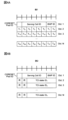
図1のUE固有PDSCH用TCI状態アクティベーション/ディアクティベーションMAC CE(TCI States Activation/Deactivation for UE-specific PDSCH MAC CE)は、CORESETプールIDフィールドと、サービングセルIDフィールドと、BWP IDフィールドと、Tiフィールドと、を含む。 The TCI States Activation/Deactivation for UE-specific PDSCH MAC CE in FIG. 1 includes a CORESET Pool ID field, a Serving Cell ID field, a BWP ID field, and a Ti field.
Tiフィールドは、1にセットされると、TCI状態ID iを有するTCI状態が、アクティベートされ、DCIのTCIフィールドのコードポイントにマップされることを示す。TCI状態がマップされるコードポイントは、1にセットされたTiフィールドを伴う全てのTCI状態の中の順序を示す位置によって決定される。CORESETプールIDは、アクティベートされたTCI状態と、TiフィールドによってセットされるDCIのTCIのコードポイントと、の間のマッピングが、CORESETプールIDを設定されたCORESETに固有であることを示す。 The Ti field, when set to 1, indicates that the TCI state with TCI State ID i is activated and mapped to a code point in the TCI field of the DCI. The code point to which the TCI state is mapped is determined by its ordinal position among all TCI states with the Ti field set to 1. The CORESET Pool-ID indicates that the mapping between the activated TCI states and the code point in the TCI of the DCI set by the Ti field is specific to the CORESET with the CORESET Pool-ID configured.
このMAC CEは、マルチDCIに基づくマルチTRPのPDSCH受信と、シングルTRPのPDSCH受信と、に用いられる。 This MAC CE is used for multi-TRP PDSCH reception based on multi-DCI and single-TRP PDSCH reception.
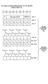
図2のUE固有PDSCH用拡張TCI状態アクティベーション/ディアクティベーションMAC CE(Enhanced TCI States Activation/Deactivation for UE-specific PDSCH MAC CE)は、予約(R)フィールド(reserved bit)と、サービングセルIDフィールドと、BWP IDフィールドと、Ciフィールドと、TCI状態IDi,jフィールドと、を含む。 The Enhanced TCI States Activation/Deactivation for UE-specific PDSCH MAC CE in FIG. 2 includes a reserved (R) field, a serving cell ID field, a BWP ID field, a C i field, and a TCI state ID i,j field.
Ciフィールドは、TCI状態IDi,2フィールドを含むオクテットが存在するか否かを示す。TCI状態IDi,jフィールドは、DCIのTCIフィールド内のi番目のコードポイントに対して指示されたj番目のTCI状態を表す。TCI状態がマップされるTCIコードポイントは、TCI状態IDi,jフィールドのセットを伴う全てのTCIコードポイントの中の順序を示す位置によって決定される。 The Ci field indicates whether an octet containing a TCI Status ID i,2 field is present. The TCI Status ID i,j field represents the jth TCI state indicated for the ith codepoint in the TCI field of the DCI. The TCI codepoint to which a TCI state is mapped is determined by its ordinal position among all TCI codepoints with a set of TCI Status ID i,j fields.
このMAC CEは、シングルDCIに基づくマルチTRPのPDSCH受信に用いられる。 This MAC CE is used for multi-TRP PDSCH reception based on a single DCI.
UE固有PDSCH用TCI状態アクティベーション/ディアクティベーションMAC CE(図1)と、UE固有PDSCH用拡張TCI状態アクティベーション/ディアクティベーションMAC CE(図2)と、の少なくとも1つは、Rel.16のMAC CEと呼ばれてもよいし、PDSCH用TCI状態MAC CEと呼ばれてもよい。At least one of the UE-specific TCI state activation/deactivation MAC CE for PDSCH (FIG. 1) and the UE-specific extended TCI state activation/deactivation MAC CE for PDSCH (FIG. 2) may be referred to as a Rel. 16 MAC CE or a TCI state MAC CE for PDSCH.
RRCシグナリングが新規空間関係情報(例えば、SpatialRelationInfo-r17)を設定してもよい。この空間関係情報は、リファレンスRS(例えば、SSB/CSI-RS/SRS)とターゲットRS(例えば、PUCCH又はPUSCHのDMRS、PRACH、SRSのようなUL RS)との間の空間関係又はQCL想定に用いられてもよい。この空間関係情報は、空間関係情報IDと、サービングセルIDと、参照信号と、の少なくとも1つを含んでもよい。参照信号は、SSBインデックスと、CSI-RSインデックス(NZP-CSI-RSリソースID)と、SRS(SRSリソースIDとUL BWPのBWP IDと)と、のいずれかを含んでもよい。 RRC signaling may configure new spatial relationship information (e.g., SpatialRelationInfo-r17). This spatial relationship information may be used for spatial relationship or QCL assumption between reference RS (e.g., SSB/CSI-RS/SRS) and target RS (e.g., UL RS such as DMRS, PRACH, SRS of PUCCH or PUSCH). This spatial relationship information may include at least one of spatial relationship information ID, serving cell ID, and reference signal. The reference signal may include any of SSB index, CSI-RS index (NZP-CSI-RS resource ID), and SRS (SRS resource ID and BWP ID of UL BWP).
RRCシグナリングに加え、MAC CEが、SRSとPUCCHとSRSとのための空間関係情報のアクティベーション/ディアクティベーションに用いられてもよい。L1シグナリング(DCI)は、aperiodic(A)-SRSとPUSCHとPRACHとPUCCHとの少なくとも1つのための(空間関係情報の)動的指示に用いられてもよい。PDCCH指示(PDCCH ordered)PRACHのための動的指示に、DCIフォーマットの新規フィールドが用いられてもよい。PUCCHのための動的指示に、DLグラント内の新規フィールドが用いられてもよい。In addition to RRC signaling, MAC CE may be used for activation/deactivation of SRS, PUCCH and spatial relationship information for SRS. L1 signaling (DCI) may be used for dynamic indication (of spatial relationship information) for at least one of aperiodic (A)-SRS, PUSCH, PRACH and PUCCH. A new field in the DCI format may be used for dynamic indication for PDCCH ordered PRACH. A new field in the DL grant may be used for dynamic indication for PUCCH.
PUCCH(PUCCH-Config内のspatialRelationInfoToAddModList)に対して64個の空間関係情報が設定可能である。統一TCIフレームワークを用いると、少なくとも64個の空間関係情報(例えば、SpatialRelationInfo-r17)が必要となる。PUSCHに対し、DCIオーバーヘッドを考慮すると、MAC CEを介してPUSCH用の空間関係情報のサブセットをアクティベートし、DCIが、アクティベートされた空間関係情報からPUSCH用の1つの空間関係情報を指示することが考えられる。例えば、MAC CEがM個の空間関係情報をアクティベートし、mビットのDCIがM個のうちの1つを選択する。例えば、Mが2である場合、mは1である。 64 pieces of spatial relationship information can be set for PUCCH (spatialRelationInfoToAddModList in PUCCH-Config). Using the unified TCI framework, at least 64 pieces of spatial relationship information (e.g., SpatialRelationInfo-r17) are required. For PUSCH, considering DCI overhead, it is possible to activate a subset of spatial relationship information for PUSCH via MAC CE, and the DCI indicates one piece of spatial relationship information for PUSCH from the activated spatial relationship information. For example, the MAC CE activates M pieces of spatial relationship information, and the m-bit DCI selects one of the M pieces. For example, if M is 2, m is 1.
しかしながら、下りリンク(DL)/上りリンク(UL)に対するビームの指示におけるレイテンシ/オーバーヘッドは、通信品質/スループットを低下させるおそれがある。However, the latency/overhead in directing beams for downlink (DL)/uplink (UL) may reduce communication quality/throughput.
そこで、本発明者らは、DL/ULに対するビーム指示の方法を着想した。 The inventors therefore came up with a method of beam direction for DL/UL.
以下、本開示に係る実施形態について、図面を参照して詳細に説明する。各実施の態様で説明する構成は、それぞれ単独で適用されてもよいし、組み合わせて適用されてもよい。Hereinafter, the embodiments of the present disclosure will be described in detail with reference to the drawings. The configurations described in each embodiment may be applied alone or in combination.
本開示において、「A/B」、「A及びBの少なくとも一方」、は互いに読み替えられてもよい。本開示において、セル、CC、キャリア、BWP、DL BWP、UL BWP、アクティブDL BWP、アクティブUL BWP、バンド、は互いに読み替えられてもよい。本開示において、インデックス、ID、インジケータ、リソースID、は互いに読み替えられてもよい。本開示において、RRC、RRCパラメータ、RRCメッセージ、上位レイヤパラメータ、情報要素(IE)、設定、は互いに読み替えられてもよい。本開示において、サポートする、制御する、制御できる、動作する、動作できる、は互いに読み替えられてもよい。In the present disclosure, "A/B" and "at least one of A and B" may be read as interchangeable. In the present disclosure, cell, CC, carrier, BWP, DL BWP, UL BWP, active DL BWP, active UL BWP, and band may be read as interchangeable. In the present disclosure, index, ID, indicator, and resource ID may be read as interchangeable. In the present disclosure, RRC, RRC parameters, RRC messages, higher layer parameters, information elements (IEs), and settings may be read as interchangeable. In the present disclosure, support, control, can be controlled, operate, and can operate may be read as interchangeable.
本開示において、アクティベート(activate)、更新(update)、指示(indicate)、有効化(enable)、指定(specify)、は互いに読み替えられてもよい。 In this disclosure, the terms activate, update, indicate, enable, and specify may be read as interchangeable.
本開示において、MAC CE、更新コマンド、アクティベーション/ディアクティベーションコマンド、は互いに読み替えられてもよい。In the present disclosure, MAC CE, update command, and activation/deactivation command may be interpreted as interchangeable.
本開示において、上位レイヤシグナリングは、例えば、Radio Resource Control(RRC)シグナリング、Medium Access Control(MAC)シグナリング、ブロードキャスト情報などのいずれか、又はこれらの組み合わせであってもよい。In the present disclosure, higher layer signaling may be, for example, Radio Resource Control (RRC) signaling, Medium Access Control (MAC) signaling, broadcast information, etc., or a combination thereof.
MACシグナリングは、例えば、MAC制御要素(MAC Control Element(MAC CE))、MAC Protocol Data Unit(PDU)などを用いてもよい。ブロードキャスト情報は、例えば、マスタ情報ブロック(Master Information Block(MIB))、システム情報ブロック(System Information Block(SIB))、最低限のシステム情報(Remaining Minimum System Information(RMSI))、その他のシステム情報(Other System Information(OSI))などであってもよい。The MAC signaling may be, for example, a MAC Control Element (MAC CE), a MAC Protocol Data Unit (PDU), etc. The broadcast information may be, for example, a Master Information Block (MIB), a System Information Block (SIB), Remaining Minimum System Information (RMSI), Other System Information (OSI), etc.
本開示において、ビーム、空間ドメインフィルタ、TCI状態(state)、QCL想定(assumption)、QCLパラメータ、空間ドメイン受信フィルタ、UE空間ドメイン受信フィルタ、UE受信ビーム、DLビーム、DL受信ビーム、DLプリコーディング、DLプリコーダ、DL-RS、TCI状態のQCLタイプD、TCI状態のQCLタイプDのRS、TCI状態又はQCL想定のQCLタイプDのRS、TCI状態又はQCL想定のQCLタイプAのRS、空間関係、空間ドメイン送信フィルタ、UE空間ドメイン送信フィルタ、UE送信ビーム、ULビーム、UL送信ビーム、ULプリコーディング、ULプリコーダ、は互いに読み替えられてもよい。本開示において、QCLタイプX-RS、QCLタイプXに関連付けられたDL-RS、QCLタイプXを有するDL-RS、DL-RSのソース、SSB、CSI-RS、は互いに読み替えられてもよい。In the present disclosure, beam, spatial domain filter, TCI state, QCL assumption, QCL parameters, spatial domain receive filter, UE spatial domain receive filter, UE receive beam, DL beam, DL receive beam, DL precoding, DL precoder, DL-RS, QCL type D in TCI state, RS of QCL type D in TCI state, RS of QCL type D in TCI state or QCL assumption, RS of QCL type A in TCI state or QCL assumption, spatial relationship, spatial domain transmit filter, UE spatial domain transmit filter, UE transmit beam, UL beam, UL transmit beam, UL precoding, UL precoder may be interpreted as interchangeable. In the present disclosure, QCL type X-RS, DL-RS associated with QCL type X, DL-RS having QCL type X, source of DL-RS, SSB, and CSI-RS may be interpreted as interchangeable.
本開示において、UL TCI状態、ULチャネル/RS(例えば、PUCCH/PUSCH/SRS/UL DMRS)に用いることができる統一TCI状態、は互いに読み替えられてもよい。本開示において、UL用のTCI状態、新規空間関係情報(例えば、spatioalRelationInfo-r17)、は互いに読み替えられてもよい。本開示において、TCI状態ID、新規空間関係情報ID(例えば、spatioalRelationInfoID-r17)、は互いに読み替えられてもよい。In the present disclosure, the UL TCI state and the unified TCI state that can be used for UL channels/RS (e.g., PUCCH/PUSCH/SRS/UL DMRS) may be interchanged. In the present disclosure, the TCI state for UL and the new spatial relationship information (e.g., spatialRelationInfo-r17) may be interchanged. In the present disclosure, the TCI state ID and the new spatial relationship information ID (e.g., spatialRelationInfoID-r17) may be interchanged.
本開示において、リファレンスRSとターゲットRS間の空間関係に関する情報、UL TCI状態に関する情報、DL及びULで共通化されたTCI状態に関する情報、統一TCI状態に関する情報、は互いに読み替えられてもよい。In the present disclosure, information regarding the spatial relationship between the reference RS and the target RS, information regarding the UL TCI state, information regarding the TCI state common to the DL and UL, and information regarding the unified TCI state may be interpreted as interchangeable.
本開示において、パネル、Uplink(UL)送信エンティティ、TRP、空間関係、制御リソースセット(COntrol REsource SET(CORESET))、PDSCH、コードワード、基地局、ある信号のアンテナポート(例えば、復調用参照信号(DeModulation Reference Signal(DMRS))ポート)、ある信号のアンテナポートグループ(例えば、DMRSポートグループ)、多重のためのグループ(例えば、符号分割多重(Code Division Multiplexing(CDM))グループ、参照信号グループ、CORESETグループ)、CORESETプール、CW、冗長バージョン(redundancy version(RV))、レイヤ(MIMOレイヤ、送信レイヤ、空間レイヤ)、は、互いに読み替えられてもよい。また、パネルIdentifier(ID)とパネルは互いに読み替えられてもよい。本開示において、TRP IDとTRPは、互いに読み替えられてもよい。In the present disclosure, panel, Uplink (UL) transmitting entity, TRP, spatial relationship, control resource set (COntrol REsource SET (CORESET)), PDSCH, codeword, base station, antenna port of a certain signal (e.g., DeModulation Reference Signal (DMRS) port), antenna port group of a certain signal (e.g., DMRS port group), group for multiplexing (e.g., Code Division Multiplexing (CDM) group, reference signal group, CORESET group), CORESET pool, CW, redundancy version (RV), layer (MIMO layer, transmission layer, spatial layer), may be read as mutually interchangeable. Also, panel identifier (ID) and panel may be read as mutually interchangeable. In the present disclosure, TRP ID and TRP may be read as mutually interchangeable.
本開示において、複数のTRPを設定されたUEは、次の少なくとも1つに基づいて、DCIに対応するTRP、DCIがスケジュールするPDSCH又はUL送信(PUCCH、PUSCH、SRSなど)に対応するTRPなどの少なくとも1つを判断してもよい。
・DCIに含まれる所定のフィールド(例えば、TRPを指定するフィールド、アンテナポートフィールド、PRI)の値。
・スケジュールされるPDSCH/PUSCHに対応するDMRS(例えば、当該DMRSの系列、リソース、CDMグループ、DMRSポート、DMRSポートグループ、アンテナポートグループなど)。
・DCIが送信されたPDCCHに対応するDMRS(例えば、当該DMRSの系列、リソース、CDMグループ、DMRSポート、DMRSポートグループなど)。
・DCIを受信したCORESET(例えば、当該CORESETのCORESETプールID、当該CORESETのID、スクランブルID(系列IDで読み替えられてもよい)、リソースなど)。
・TCI状態、QCL想定、空間関係情報などに用いられるRS(RS関連(related)グループなど)。
In the present disclosure, a UE configured with multiple TRPs may determine at least one of the TRPs corresponding to a DCI, the TRP corresponding to a PDSCH or UL transmission (PUCCH, PUSCH, SRS, etc.) scheduled by the DCI, etc., based on at least one of the following:
- Values of certain fields included in DCI (e.g., a field specifying a TRP, an antenna port field, a PRI).
DMRS corresponding to the scheduled PDSCH/PUSCH (e.g., the sequence, resource, CDM group, DMRS port, DMRS port group, antenna port group, etc. of the DMRS).
- DMRS corresponding to the PDCCH on which the DCI is transmitted (e.g., the sequence, resource, CDM group, DMRS port, DMRS port group, etc. of the DMRS).
- The CORESET that received the DCI (for example, the CORESET pool ID of the CORESET, the ID of the CORESET, the scramble ID (which may be replaced with the sequence ID), resources, etc.).
- RS (e.g., RS related groups) used for TCI states, QCL assumptions, spatial relationship information, etc.
本開示において、シングルPDCCH(DCI)は、第1のスケジューリングタイプ(例えば、スケジューリングタイプA(又はタイプ1))のPDCCH(DCI)と呼ばれてもよい。また、マルチPDCCH(DCI)は、第2のスケジューリングタイプ(例えば、スケジューリングタイプB(又はタイプ2))のPDCCH(DCI)と呼ばれてもよい。In the present disclosure, a single PDCCH (DCI) may be referred to as a PDCCH (DCI) of a first scheduling type (e.g., scheduling type A (or type 1)). Also, a multi-PDCCH (DCI) may be referred to as a PDCCH (DCI) of a second scheduling type (e.g., scheduling type B (or type 2)).
本開示において、シングルPDCCHは、マルチTRPが理想的バックホール(ideal backhaul)を利用する場合にサポートされると想定されてもよい。マルチPDCCHは、マルチTRP間が非理想的バックホール(non-ideal backhaul)を利用する場合にサポートされると想定されてもよい。In this disclosure, a single PDCCH may be assumed to be supported when multiple TRPs use an ideal backhaul. A multi-PDCCH may be assumed to be supported when multiple TRPs use a non-ideal backhaul.
なお、理想的バックホールは、DMRSポートグループタイプ1、参照信号関連グループタイプ1、アンテナポートグループタイプ1、CORESETプールタイプ1、などと呼ばれてもよい。非理想的バックホールは、DMRSポートグループタイプ2、参照信号関連グループタイプ2、アンテナポートグループタイプ2、CORESETプールタイプ2、などと呼ばれてもよい。名前はこれらに限られない。In addition, the ideal backhaul may be called DMRS
本開示において、マルチTRP,マルチTRPシステム、マルチTRP送信、マルチPDSCH、は互いに読み替えられてもよい。本開示において、シングルDCI、シングルPDCCH、シングルDCIに基づくマルチTRPシステム、少なくとも1つのTCIコードポイント上の2つのTCI状態をアクティベートされること、1つのDCIが2つのTCI状態に関連付けられること、は互いに読み替えられてもよい。本開示において、マルチDCI、マルチPDCCH、マルチDCIに基づくマルチTRPシステム、(CORESETに対して)CORESETプールインデックスが設定されること、2つのDCIが2つのTCI状態に関連付けられること、は互いに読み替えられてもよい。シングルTRP、シングルTRPシステム、シングルTRP送信、シングルPDSCH、TCIコードポイントに上の2以上のTCI状態が関連付けられず、且つCORESETプールインデックスが設定されないこと、は互いに読み替えられてもよい。In the present disclosure, multi-TRP, multi-TRP system, multi-TRP transmission, and multi-PDSCH may be interchanged. In the present disclosure, single DCI, single PDCCH, multi-TRP system based on single DCI, activating two TCI states on at least one TCI code point, and associating one DCI with two TCI states may be interchanged. In the present disclosure, multi-DCI, multi-PDCCH, multi-TRP system based on multi-DCI, setting a CORESET pool index (for CORESET), and associating two DCI with two TCI states may be interchanged. Single TRP, single TRP system, single TRP transmission, single PDSCH, and not associating two or more TCI states with a TCI code point and not setting a CORESET pool index may be interchanged.
(無線通信方法)
<第1の実施形態>
PDSCH TCI状態とPUSCH TCI状態に対して異なるMAC CEが用いられてもよい。PUSCH TCI状態アクティベーションのための新規MAC CEが導入されてもよい。新規MAC CEは、新規logical channel ID(LCID)を有してもよい。
(Wireless communication method)
First Embodiment
Different MAC CEs may be used for the PDSCH TCI state and the PUSCH TCI state. A new MAC CE for PUSCH TCI state activation may be introduced. The new MAC CE may have a new logical channel ID (LCID).
新規MAC CEは、次の通知方法1-1から1-3の少なくとも1つに従ってもよい。通知方法1-1から1-3は同じMAC CEであってもよいし、通知方法1-1から1-3の少なくとも1つが他のMAC CEと異なってもよい。シングルTRP PUSCH送信は、Rel.15の機構を用いるPUSCH送信であってもよい。The new MAC CE may follow at least one of the following notification methods 1-1 to 1-3. Notification methods 1-1 to 1-3 may be the same MAC CE, or at least one of notification methods 1-1 to 1-3 may be different from other MAC CEs. The single TRP PUSCH transmission may be a PUSCH transmission using the Rel. 15 mechanism.
《通知方法1-1》
新規MAC CEは、シングルTRP PUSCH送信用MAC CEであってもよい。
<Notification method 1-1>
The new MAC CE may be a MAC CE for a single TRP PUSCH transmission.
シングルTRP PUSCH送信に対し、MAC CEは、RRCによって設定されるTCI状態から、PUSCH用のX個のTCI状態をアクティベートしてもよい。アクティベートされたTCI状態は、PUSCH TCIを指示するDCIフィールドのコードポイントにマップされてもよい。For a single TRP PUSCH transmission, the MAC CE may activate X TCI states for PUSCH from the TCI states configured by the RRC. The activated TCI states may be mapped to code points of the DCI field indicating the PUSCH TCI.
PUSCH用にアクティベートされるTCI状態の最大数は、仕様に規定されてもよい。例えば、アクティベートされるTCI状態の最大数は、2、4、8、又はそれ以外の数であってもよい。The maximum number of TCI states that may be activated for the PUSCH may be specified. For example, the maximum number of activated TCI states may be 2, 4, 8, or some other number.
[例1]
図3Aの例において、MAC CEは、Rフィールドと、サービングセルIDフィールドと、BWP IDフィールドと、Tiフィールドと、を含む。
[Example 1]
In the example of FIG. 3A, the MAC CE includes an R field, a serving cell ID field, a BWP ID field, and a Ti field.
Tiフィールドは、1にセットされると、TCI状態ID iを有するTCI状態が、アクティベートされることと、PUSCH用TCI状態を指示するDCIコードポイントにマップされることと、を示してもよい。1にセットされるTiフィールドを伴う1番目のTCI状態は、コードポイント値0にマップされてもよい。1にセットされるTiフィールドを伴うn番目のTCI状態は、コードポイント値n-1にマップされてもよい。
The T i field, when set to 1, may indicate that the TCI state with TCI state ID i is activated and is mapped to a DCI codepoint indicating the TCI state for PUSCH. The first TCI state with T i field set to 1 may be mapped to
1にセットされるTiフィールドの最大数は、仕様又はRRC設定に従ってもよい。例えば、BWP当たり8に制限されてもよい。 The maximum number of Ti fields that may be set to 1 may be according to specification or RRC configuration, e.g., may be limited to 8 per BWP.
MAC CEサイズは、RRC 情報要素(IE)内においてUL用に設定されたTCI状態の数に依存してもよい。この例においては、64個のTCI状態が設定される。The MAC CE size may depend on the number of TCI states configured for the UL in the RRC information element (IE). In this example, 64 TCI states are configured.
[例2]
図3Bの例において、MAC CEは、Rフィールドと、サービングセルIDフィールドと、BWP IDフィールドと、TCI状態IDiフィールドと、を含む。
[Example 2]
In the example of FIG. 3B, the MAC CE includes an R field, a serving cell ID field, a BWP ID field, and a TCI state ID i field.
TCI状態IDiフィールドは、アクティベートされ、PUSCH用のTCI状態を指示するDCIフィールドのコードポイント(i)にマップされる、TCI状態を示してもよい。 The TCI State ID i field may indicate the TCI state that is activated and is mapped to code point (i) of the DCI field that indicates the TCI state for PUSCH.
この例において、UL TCI状態の最大数は64であり、TCI状態IDフィールドは6ビットである。TCI状態IDフィールドのサイズは他の数であってもよい。例えば、UL TCI状態の最大数は128であり、TCI状態IDフィールドは7ビットであってもよい。In this example, the maximum number of UL TCI states is 64 and the TCI State ID field is 6 bits. The size of the TCI State ID field may be other numbers. For example, the maximum number of UL TCI states may be 128 and the TCI State ID field may be 7 bits.
《通知方法1-2》
新規MAC CEは、マルチDCIに基づくマルチTRP PUSCH送信用MAC CEであってもよい。
<Notification method 1-2>
The new MAC CE may be a MAC CE for multi-TRP PUSCH transmission based on multi-DCI.
新規MAC CEは、次の選択肢1及び2のいずれかに従ってもよい。
The new MAC CE may follow either of the following
[選択肢1]
CORESETプールIDがMAC CEに含まれてもよい。CORESETプールIDが0にセットされる場合、MAC CEは、0に等しいCORESETプールIDによってスケジュールされるPUSCHに適用されてもよい。CORESETプールIDが1にセットされる場合、MAC CEは、1に等しいCORESETプールIDによってスケジュールされるPUSCHに適用されてもよい。
[Option 1]
A CORESET Pool-ID may be included in the MAC CE. If the CORESET Pool-ID is set to 0, the MAC CE may apply to PUSCHs scheduled with a CORESET Pool-ID equal to 0. If the CORESET Pool-ID is set to 1, the MAC CE may apply to PUSCHs scheduled with a CORESET Pool-ID equal to 1.
その他の特徴は、通知方法1-1と同様であってもよい。 Other features may be similar to notification method 1-1.
[例1]
図4Aの例において、MAC CEは、CORESETプールIDフィールドと、サービングセルIDフィールドと、BWP IDフィールドと、Tiフィールドと、を含む。
[Example 1]
In the example of FIG. 4A, the MAC CE includes a CORESET Pool ID field, a Serving Cell ID field, a BWP ID field, and a Ti field.
[例2]
図4Bの例において、MAC CEは、CORESETプールIDフィールドと、サービングセルIDフィールドと、BWP IDフィールドと、Rフィールドと、TCI状態IDiフィールドと、を含む。
[Example 2]
In the example of FIG. 4B, the MAC CE includes a CORESET Pool ID field, a Serving Cell ID field, a BWP ID field, an R field, and a TCI State ID i field.
[選択肢2]
新規MAC CEは、通知方法1-1を再利用してもよい。この場合、異なるCORESETプールIDによってスケジュールされるPUSCHに対して、TCI状態の同じセットがアクティベートされてもよい。
[Option 2]
The new MAC CE may reuse notification method 1-1, in which case the same set of TCI states may be activated for PUSCHs scheduled by different CORESET Pool-IDs.
《通知方法1-3》
新規MAC CEは、シングルDCIに基づくマルチTRP PUSCH送信用MAC CEであってもよい。
<<Notification Method 1-3>>
The new MAC CE may be a MAC CE for multi-TRP PUSCH transmission based on a single DCI.
シングルDCIに基づくマルチTRP PUSCH送信に対し、MAC CEは、RRCによって設定されるTCI状態から、PUSCH用のTCI状態のX個の組み合わせをアクティベートしてもよい。TCI状態のアクティベートされた組み合わせは、PUSCH TCIを指示するDCIフィールドのコードポイントにマップされてもよい。For a multi-TRP PUSCH transmission based on a single DCI, the MAC CE may activate X combinations of TCI states for PUSCH from the TCI states configured by the RRC. The activated combinations of TCI states may be mapped to code points of the DCI field indicating the PUSCH TCI.
各組み合わせは、Y個のTCI状態を含んでもよい。TCI状態の1つの組み合わせが、マルチTRPに基づくPUSCH送信に用いられてもよい。ここで、各TCI状態が、各TRPへのPUSCH送信に対応してもよい。Each combination may include Y TCI states. One combination of TCI states may be used for a multi-TRP based PUSCH transmission, where each TCI state may correspond to a PUSCH transmission to each TRP.
PUSCH用のTCI状態のアクティベートされる組み合わせの最大数は、仕様に規定されてもよい。例えば、アクティベートされるTCI状態の最大数は、2、4、8、又はそれ以外の数であってもよい。The maximum number of activated combinations of TCI states for the PUSCH may be specified. For example, the maximum number of activated TCI states may be 2, 4, 8, or some other number.
DCIコードポイントにマップされる各組み合わせ内のTCI状態の数が、仕様に規定されてもよい。The number of TCI states within each combination that are mapped to a DCI code point may be specified in the specification.
図5の例において、MAC CEは、Rフィールドと、サービングセルIDフィールドと、BWP IDフィールドと、Ciフィールドと、TCI状態IDi,jフィールドと、を含む。 In the example of FIG. 5, the MAC CE includes an R field, a serving cell ID field, a BWP ID field, a C i field, and a TCI state ID i,j field.
Ciフィールドは、TCI状態IDi,2フィールドを含むオクテットが存在するか否かを示す。TCI状態IDi,1フィールド及びTCI状態IDi,2フィールドは、アクティベートされ、PUSCH用のTCI状態を指示するDCIフィールドのコードポイント(i)にマップされる、TCI状態を示してもよい。 The C i field indicates whether an octet containing a TCI State ID i,2 field is present. The TCI State ID i,1 and TCI State ID i,2 fields may indicate the TCI state that is activated and is mapped to codepoint (i) of the DCI field indicating the TCI state for PUSCH.
この例において、UL TCI状態の最大数は64であり、TCI状態IDフィールドは6ビットである。TCI状態IDフィールドのサイズは他の数であってもよい。例えば、UL TCI状態の最大数は128であり、TCI状態IDフィールドは7ビットであってもよい。In this example, the maximum number of UL TCI states is 64 and the TCI State ID field is 6 bits. The size of the TCI State ID field may be other numbers. For example, the maximum number of UL TCI states may be 128 and the TCI State ID field may be 7 bits.
この例において、各DCIコードポイントは、2つのTCI状態(TCI状態の1つの組み合わせ)にマップされる。各DCIコードポイントにマップされるTCI状態の数は、他の数Yであってもよい。In this example, each DCI code point is mapped to two TCI states (one combination of TCI states). The number of TCI states mapped to each DCI code point may be another number Y.
以上の第1の実施形態によれば、PUSCHに対して適切にTCI状態を指示できる。According to the above first embodiment, the TCI state can be appropriately indicated for the PUSH.
<第2の実施形態>
PDSCHとPUSCHの両方に適用されるTCI状態アクティベーション/ディアクティベーションに、同じMAC CEが用いられてもよい。
Second Embodiment
The same MAC CE may be used for TCI state activation/deactivation that applies to both PDSCH and PUSCH.
PDSCH TCI アクティベーション用のRel.16 MAC CEが再利用されてもよい。MAC CE内の指示が、PDSCHとPUSCHの両方に適用されてもよい。The Rel. 16 MAC CE for PDSCH TCI activation may be reused. The indication in the MAC CE may apply to both PDSCH and PUSCH.
TCI アクティベーション用の新規MAC CEが導入されてもよい。MAC CE内の指示が、PDSCHとPUSCHの両方に適用されてもよい。A new MAC CE for TCI activation may be introduced. The indication in the MAC CE may apply to both PDSCH and PUSCH.
PUSCH送信用のTCI状態のアクティベーション/ディアクティベーションは、次の通知方法2-1から2-5の少なくとも1つに従ってもよい。シングルTRP PUSCH送信は、Rel.15の機構を用いるPUSCH送信であってもよい。Activation/deactivation of the TCI state for PUSCH transmission may follow at least one of the following notification methods 2-1 to 2-5. Single-TRP PUSCH transmission may be a PUSCH transmission using the Rel. 15 mechanisms.
《通知方法2-1》
シングルTRP PUSCH送信に対して、UE固有PDSCH用TCI状態アクティベーション/ディアクティベーションMAC CE(図1)が再利用されてもよい。
<Notification method 2-1>
For single TRP PUSCH transmission, the UE-specific TCI state activation/deactivation MAC CE for PDSCH (FIG. 1) may be reused.
Tiフィールドは、1にセットされると、TCI状態ID iを有するTCI状態が、アクティベートされることと、PUSCH用TCI状態を指示するDCIコードポイントにマップされることと、を示してもよい。1にセットされるTiフィールドを伴う1番目のTCI状態は、コードポイント値0にマップされてもよい。1にセットされるTiフィールドを伴うn番目のTCI状態は、コードポイント値n-1にマップされてもよい。
The T i field, when set to 1, may indicate that the TCI state with TCI state ID i is activated and is mapped to a DCI codepoint indicating the TCI state for PUSCH. The first TCI state with T i field set to 1 may be mapped to
PUSCHに対して設定されるTCI状態の数が、PDSCHに対して設定されるTCI状態の数よりも小さい場合、最初のX個のTiフィールドがPUSCHに適用されてもよい。Xは、PUSCHに対して設定されるTCI状態の数であってもよい。 If the number of TCI states configured for the PUSCH is less than the number of TCI states configured for the PDSCH, then the first X Ti fields may be applied to the PUSCH, where X may be the number of TCI states configured for the PUSCH.
PUSCHに対してアクティベートされるTCI状態の最大数が、PDSCHに対してアクティベートされるTCI状態の数よりも小さい場合、1にセットされた最初のX個のTiフィールドが、PUSCHに対してアクティベートされるTCI状態を示してもよい。Xは、PUSCHに対してアクティベートされるTCI状態の最大数であってもよい。 If the maximum number of TCI states activated for the PUSCH is less than the number of TCI states activated for the PDSCH, the first X Ti fields set to 1 may indicate the TCI states activated for the PUSCH, where X may be the maximum number of TCI states activated for the PUSCH.
図6の例において、CORESETプールIDフィールドと、サービングセルIDフィールドと、BWP IDフィールドと、Tiフィールドと、を含む。この例において、PDSCHに対して設定されるTCI状態の数が128であり、PUSCHに対して設定されるTCI状態の数が64であり、最初の64個のTiフィールドがPUSCHに適用されてもよい。 6, the CORESET Pool ID field includes a Serving Cell ID field, a BWP ID field, and a Ti field. In this example, the number of TCI states configured for the PDSCH is 128, the number of TCI states configured for the PUSCH is 64, and the first 64 Ti fields may apply to the PUSCH.
《通知方法2-2》
マルチDCIに基づくマルチTRP PUSCH送信に対して、UE固有PDSCH用TCI状態アクティベーション/ディアクティベーションMAC CE(図1)が再利用されてもよい。その他の特徴は、通知方法2-1に同様であってもよい。
<Notification method 2-2>
For multi-TRP PUSCH transmission based on multi-DCI, the UE-specific TCI state activation/deactivation MAC CE for PDSCH (FIG. 1) may be reused. Other features may be similar to notification method 2-1.
MAC CEは、次の選択肢1及び2のいずれかに従ってもよい。
The MAC CE may follow either of the following
[選択肢1]
CORESETプールIDが0にセットされる場合、MAC CEは、0に等しいCORESETプールIDによってスケジュールされるPUSCHに適用されてもよい。CORESETプールIDが1にセットされる場合、MAC CEは、1に等しいCORESETプールIDによってスケジュールされるPUSCHに適用されてもよい。
[Option 1]
If the CORESET Pool-ID is set to 0, then the MAC CE may be applied to a PUSCH scheduled with a CORESET Pool-ID equal to 0. If the CORESET Pool-ID is set to 1, then the MAC CE may be applied to a PUSCH scheduled with a CORESET Pool-ID equal to 1.
[選択肢2]
CORESETプールIDが0にセットされる場合のみ、MAC CEがPUSCHに適用されてもよい。この場合、異なるCORESETプールIDによってスケジュールされるPUSCHに対して、TCI状態の同じセットがアクティベートされてもよい。
[Option 2]
The MAC CE may be applied to PUSCH only if the CORESET Pool-ID is set to 0. In this case, the same set of TCI states may be activated for PUSCHs scheduled by different CORESET Pool-IDs.
[バリエーション]
Tiフィールドの複数のセットが存在し、各セットが各CORESETプールIDに対応してもよい。
[Variation]
There may be multiple sets of Ti fields, one corresponding to each CORESET Pool ID.
MAC CEがPフィールドを含んでもよい。Pフィールドが1にセットされる場合、Tiフィールドの2番目のセットが存在してもよい。そうでない場合、Tiフィールドの2番目のセットが存在しなくてもよい。 The MAC CE may include a P field. If the P field is set to 1, then a second set of Ti fields may be present. Otherwise, the second set of Ti fields may not be present.
図7の例において、MAC CEは、Pフィールドと、サービングセルIDフィールドと、BWP IDフィールドと、Tiフィールドと、を含む。この例において、Pフィールドは1にセットされ、MAC CEは、Tiフィールドの1番目のセットと、Tiフィールドの2番目のセットと、を含む。Tiフィールドの1番目のセットは、0のCORESETプールIDに対応し、Tiフィールドの2番目のセットは、1のCORESETプールIDに対応する。 In the example of Figure 7, the MAC CE includes a P field, a Serving Cell ID field, a BWP ID field, and a Ti field. In this example, the P field is set to 1, and the MAC CE includes a first set of Ti fields and a second set of Ti fields. The first set of Ti fields corresponds to a CORESET Pool-ID of 0, and the second set of Ti fields corresponds to a CORESET Pool-ID of 1.
《通知方法2-3》
シングルTRP PUSCH送信に対して、UE固有PDSCH用拡張TCI状態アクティベーション/ディアクティベーションMAC CE(図2)が再利用されてもよい。
<Notification method 2-3>
For single TRP PUSCH transmission, the UE-specific TCI state activation/deactivation MAC CE for PDSCH (FIG. 2) may be reused.
MAC CEは、次の選択肢1及び2のいずれかに従ってもよい。
The MAC CE may follow either of the following
[選択肢1]
TCI状態IDi,1フィールドは、アクティベートされ、PUSCH用のTCI状態を指示するDCIフィールドのコードポイント(i)にマップされる、TCI状態を示してもよい。
[Option 1]
The TCI State ID i,1 field may indicate the TCI state that is activated and is mapped to code point (i) of the DCI field that indicates the TCI state for PUSCH.
PUSCHに対してアクティベートされるTCI状態の最大数が、PDSCHに対してアクティベートされるTCI状態ペアの数よりも小さい場合、最初のX個のTCI状態IDi,1フィールドが、PUSCHに対して適用されてもよい。Xは、PUSCHに対してアクティベートされるTCI状態の最大数であってもよい。 If the maximum number of TCI states activated for the PUSCH is less than the number of TCI state pairs activated for the PDSCH, then the first X TCI State ID i,1 fields may apply for the PUSCH, where X may be the maximum number of TCI states activated for the PUSCH.
図8Aの例において、TCI状態ID0,1フィールドは、PUSCHに適用され、コードポイント0にマップされる。TCI状態ID1,1フィールドは、PUSCHに適用され、コードポイント1にマップされる。
8A, the TCI State ID 0,1 field applies to the PUSCH and is mapped to code
[選択肢2]
TCI状態IDi,jフィールドは、アクティベートされ、PUSCH用のTCI状態を指示するDCIフィールドのコードポイント(i)にマップされる、(j番目の)TCI状態を示してもよい。
[Option 2]
The TCI State ID i,j field may indicate the (jth) TCI state that is activated and mapped to code point (i) of the DCI field indicating the TCI state for PUSCH.
PUSCHに対してアクティベートされるTCI状態の最大数が、PDSCHに対してアクティベートされるTCI状態の数よりも小さい場合、最初のX個のTCI状態IDi,jフィールドが、PUSCHに対して適用されてもよい。Xは、PUSCHに対してアクティベートされるTCI状態の最大数であってもよい。 If the maximum number of TCI states activated for the PUSCH is less than the number of TCI states activated for the PDSCH, then the first X TCI State ID i,j fields may apply for the PUSCH, where X may be the maximum number of TCI states activated for the PUSCH.
図8Bの例において、TCI状態ID0,1フィールドは、PUSCHに適用され、コードポイント0にマップされる。TCI状態ID0,2フィールドは、PUSCHに適用され、コードポイント1にマップされる。TCI状態ID1,1フィールドは、PUSCHに適用され、コードポイント2にマップされる。TCI状態ID1,2フィールドは、PUSCHに適用され、コードポイント3にマップされる。
In the example of Figure 8B, the TCI State ID 0,1 field applies to the PUSCH and is mapped to code
《通知方法2-4》
マルチDCIに基づくマルチTRP PUSCH送信に対して、UE固有PDSCH用拡張TCI状態アクティベーション/ディアクティベーションMAC CE(図2)が再利用されてもよい。
<Notification method 2-4>
For multi-TRP PUSCH transmission based on multi-DCI, the UE-specific enhanced TCI state activation/deactivation MAC CE for PDSCH (FIG. 2) may be reused.
[選択肢1]
TCI状態IDi,1フィールド及びTCI状態IDi,2フィールドは、アクティベートされ、PUSCH用のTCI状態を指示するDCIフィールドのコードポイント(i)にマップされる、TCI状態を示してもよい。
[Option 1]
The TCI State ID i,1 and TCI State ID i,2 fields may indicate the TCI state that is activated and mapped to codepoint (i) of the DCI field that indicates the TCI state for PUSCH.
PUSCHに対してアクティベートされるTCI状態ペアの最大数が、PDSCHに対してアクティベートされるTCI状態ペアの数よりも小さい場合、TCI状態IDi,1フィールド及びTCI状態IDi,2フィールドの最初のX個のペアが、PUSCHに対してアクティベートされるTCI状態を示してもよい。Xは、PUSCHに対するTCI状態のアクティベートされるペアの最大数であってもよい。 If the maximum number of TCI state pairs activated for PUSCH is less than the number of TCI state pairs activated for PDSCH, the first X pairs of the TCI State ID i,1 and TCI State ID i,2 fields may indicate the TCI states activated for PUSCH, where X may be the maximum number of activated pairs of TCI states for PUSCH.
《通知方法2-5》
ULグラントDCI内におけるUL-TCI状態指示のためのフィールドのサイズ(ビット数)は、特定用途のTCI状態の数に依存してもよい。特定用途のTCI状態は、MAC CEによってアクティベートされてもよい。特定用途のTCI状態は、アクティブUL TCI状態と、PDSCH用DL TCI状態と、の少なくとも1つであってもよい。ULグラントDCIは、DCIフォーマット0_0、0_1、0_2の少なくとも1つであってもよい。
<Notification method 2-5>
The size (number of bits) of the field for UL-TCI state indication in the UL grant DCI may depend on the number of application-specific TCI states. The application-specific TCI states may be activated by the MAC CE. The application-specific TCI states may be at least one of an active UL TCI state and a DL TCI state for PDSCH. The UL grant DCI may be at least one of DCI formats 0_0, 0_1, and 0_2.
例えば、MAC CE内においてアクティベートされる特定用途のTCI状態の数がNである場合、UL-TCI状態指示のためのフィールドのビット数は、ceil(log2(N))であってもよい。For example, if the number of application-specific TCI states activated in a MAC CE is N, the number of bits in the field for UL-TCI state indication may be ceil(log2(N)).
《第2の実施形態の変形例》
TCI状態アクティベーションのための新規MAC CEが導入されてもよい。MAC CE内の指示がPDSCH及びPUSCHの両方に適用されてもよい。
Modification of the Second Embodiment
A new MAC CE for TCI state activation may be introduced. The indication in the MAC CE may apply to both PDSCH and PUSCH.
新規MAC CEの内容は、通知方法2-1から2-4のいずれかと同じであってもよい。新規MAC CEとRel.16のMAC CEに対して、異なるLCIDが用いられてもよい。The contents of the new MAC CE may be the same as any of notification methods 2-1 to 2-4. Different LCIDs may be used for the new MAC CE and the Rel. 16 MAC CE.
次のケース1及び2がサポートされてもよいし、次のケース1及び2のいずれがサポートされるかが上位レイヤシグナリングによって設定されてもよい。
[ケース1]UEは、Rel.16のMAC CEと新規MAC CEの両方を受信する。
[ケース2]UEは、新規MAC CEの両方を受信する。
The following
[Case 1] The UE receives both the Rel.16 MAC CE and the new MAC CE.
[Case 2] The UE receives both new MAC CEs.
以上の第2の実施形態によれば、PDSCH及びPUSCHに対して適切にTCI状態を指示できる。According to the above second embodiment, the TCI status can be appropriately indicated for PDSCH and PUSH.
<第3の実施形態>
PDSCHとPUSCHのためのTCI状態アクティベーション/ディアクティベーションに同じMAC CEが用いられてもよい。MAC CEがPDSCH及びPUSCHのいずれに適用されるかが当該MAC CE内の1ビットの指示に基づいてもよい。
Third Embodiment
The same MAC CE may be used for TCI state activation/deactivation for PDSCH and PUSCH, and a one-bit indication in the MAC CE may be used to indicate whether the MAC CE applies to PDSCH or PUSCH.
PDSCH TCI アクティベーション用のRel.16 MAC CEが再利用されてもよい。MAC CE内の指示が、1ビットの指示に基づいて、PDSCHとPUSCHのいずれかに適用されてもよい。The Rel. 16 MAC CE for PDSCH TCI activation may be reused. The indication in the MAC CE may apply to either PDSCH or PUSCH based on a one-bit indication.
第2の実施形態におけるMAC CEの内容及びUE動作に基づき、MAC CE内の1ビットが、そのMAC CEがPDSCH及びPUSCHのいずれに適用されるかを示してもよい。Based on the contents of the MAC CE and the UE operation in the second embodiment, one bit in the MAC CE may indicate whether the MAC CE applies to PDSCH or PUSCH.
このビットが0にセットされる場合、MAC CEはPDSCHに適用されてもよい。このビットが1にセットされる場合、MAC CEはPUSCHに適用され、PUSCHに対して第2の実施形態におけるUE動作が適用されてもよい。If this bit is set to 0, the MAC CE may be applied to the PDSCH. If this bit is set to 1, the MAC CE may be applied to the PUSCH, and the UE operation in the second embodiment may be applied to the PUSCH.
UE固有PDSCH用拡張TCI状態アクティベーション/ディアクティベーションMAC CE(図2)に対し、1つのRフィールドがPDSCH又はPUSCHの識別子として用いられてもよい。Rフィールドのビットが0にセットされる場合、MAC CEはPDSCHに適用されてもよい。このビットが1にセットされる場合、MAC CEはPUSCHに適用され、PUSCHに対して通知方法2-3/2-4におけるUE動作が適用されてもよい。For the UE-specific PDSCH extended TCI state activation/deactivation MAC CE (Figure 2), one R field may be used as an identifier for PDSCH or PUSCH. If the bit of the R field is set to 0, the MAC CE may apply to PDSCH. If this bit is set to 1, the MAC CE applies to PUSCH and the UE actions in notification method 2-3/2-4 may apply to PUSCH.
図9の例において、UE固有PDSCH用拡張TCI状態アクティベーション/ディアクティベーションMAC CE内の最初のRフィールドが、PDSCH又はPUSCHの識別子として用いられてもよい。In the example of Figure 9, the first R field in the UE-specific Extended TCI State Activation/Deactivation MAC CE for PDSCH may be used as an identifier for PDSCH or PUSH.
《第3の実施形態の変形例》
UE固有PDSCH用TCI状態アクティベーション/ディアクティベーションMAC CE(図1)において、Rフィールドが用いられていないため、このMAC CEが再利用されず、新規MAC CEが規定されてもよい。
Modification of the Third Embodiment
In the UE-specific TCI state activation/deactivation MAC CE for PDSCH (FIG. 1), since the R field is not used, this MAC CE is not reused and a new MAC CE may be defined.
TCI アクティベーション用の新規MAC CEが導入されてもよい。MAC CE内の指示が、1ビットの指示に基づいて、PDSCHとPUSCHのいずれかに適用されてもよい。A new MAC CE for TCI activation may be introduced. The indication in the MAC CE may apply to either PDSCH or PUSCH based on a one-bit indication.
通知方法2-1から2-4のいずれかにおけるMAC CEの内容及びUE動作に基づき、MAC CE内の1ビットが、そのMAC CEがPDSCH及びPUSCHのいずれに適用されるかを示してもよい。このビットが0にセットされる場合、MAC CEはPDSCHに適用されてもよい。このビットが1にセットされる場合、MAC CEはPUSCHに適用され、PUSCHに対して通知方法2-1から2-4のいずれかにおけるUE動作が適用されてもよい。Based on the contents of the MAC CE and the UE operation in any of notification methods 2-1 to 2-4, one bit in the MAC CE may indicate whether the MAC CE applies to the PDSCH or the PUSCH. If this bit is set to 0, the MAC CE may apply to the PDSCH. If this bit is set to 1, the MAC CE may apply to the PUSCH, and the UE operation in any of notification methods 2-1 to 2-4 may apply to the PUSCH.
[例1]
図10Aの例において、通知方法2-1/2-2に基づく新規MAC CEに、1ビットのXフィールドが導入されてもよい。Xフィールドは、PDSCH又はPUSCHの識別子であってもよい。
[Example 1]
10A, a 1-bit X field may be introduced into the new MAC CE based on the notification method 2-1/2-2. The X field may be an identifier of the PDSCH or PUSCH.
[例2]
図10Bの例において、通知方法2-3/2-4に基づく新規MAC CEにおける最初のRフィールドは、PDSCH又はPUSCHの識別子として用いられてもよい。
[Example 2]
In the example of FIG. 10B, the first R field in the new MAC CE based on notification method 2-3/2-4 may be used as an identifier of the PDSCH or PUSCH.
新規MAC CEとRel.16のMAC CEに対して、異なるLCIDが用いられてもよい。Different LCIDs may be used for the new MAC CE and the Rel. 16 MAC CE.
次のケース1及び2がサポートされてもよいし、次のケース1及び2のいずれがサポートされるかが上位レイヤシグナリングによって設定されてもよい。
[ケース1]UEは、Rel.16のMAC CEと新規MAC CEの両方を受信する。
[ケース2]UEは、新規MAC CEの両方を受信する。
The following
[Case 1] The UE receives both the Rel.16 MAC CE and the new MAC CE.
[Case 2] The UE receives both new MAC CEs.
以上の第3の実施形態によれば、同じ種類のMAC CEによって、PDSCH及びPUSCHに対して適切にTCI状態を指示できる。According to the above third embodiment, the TCI state can be appropriately indicated for PDSCH and PUSH using the same type of MAC CE.
<第4の実施形態>
UEは、複数のサービングセル/BWPに対する同時TCI状態アクティベーション(更新)をサポートしてもよい。
Fourth Embodiment
The UE may support simultaneous TCI state activation (update) for multiple serving cells/BWPs.
RRCは、X個までの適用可能CCリストを設定してもよい。 The RRC may configure up to X applicable CC lists.
PUSCH用にアクティベートされたTCI状態が、MAC CEによって指示されたCC(サービングセル)と同じ適用可能リスト内の全てのCC/BWPに適用されてもよい。The TCI state activated for PUSH may apply to all CCs/BWPs in the same applicable list as the CC (serving cell) indicated by the MAC CE.
図11の例において、UEは、CC#0、#1、#2、#3を示す適用可能CCリストと、各CC/BWPに対して1以上のTCI状態を示すTCI状態リストと、を設定される。MAC CEによってCC#0の1つのTCI状態がアクティベートされる場合、CC#1、#2、#3において、対応するTCI状態がアクティベートされる。In the example of Figure 11, the UE is configured with an applicable CC list indicating
複数のサービングセル/BWPに対する同時TCI状態アクティベーションは、シングルTRPのみに適用されてもよいし、シングルTRP及びマルチTRPに適用されてもよい。Simultaneous TCI state activation for multiple serving cells/BWPs may apply to single TRP only or to single TRP and multi-TRP.
以上の第4の実施形態によれば、低いオーバヘッド及び低いレイテンシのビーム指示を実現できる。 According to the above fourth embodiment, beam instruction can be achieved with low overhead and low latency.
<第5の実施形態>
第1から第3の実施形態の少なくとも1つに対し、PUSCH TCI状態アクティベーション用のMAC CEをサポートするか否かを示すUE能力(capability)が規定されてもよい。対応するUE能力が報告された場合のみ、第1から第3の実施形態の少なくとも1つが適用可能であってもよい。
Fifth embodiment
For at least one of the first to third embodiments, a UE capability may be defined indicating whether or not the MAC CE for PUSCH TCI state activation is supported. At least one of the first to third embodiments may be applicable only if the corresponding UE capability is reported.
第1から第3の実施形態の少なくとも1つに対し、RRCパラメータ(IE)が、PUSCH TCI状態アクティベーション用のMAC CEが有効であるか否かを設定してもよい。対応すRRCパラメータが設定された場合のみ、第1から第3の実施形態の少なくとも1つが適用可能であってもよい。For at least one of the first to third embodiments, an RRC parameter (IE) may configure whether or not the MAC CE for PUSCH TCI state activation is enabled. At least one of the first to third embodiments may be applicable only if the corresponding RRC parameter is configured.
第4の実施形態に対し、複数のCC/BWPに跨る同時PUSCH TCI状態アクティベーションをサポートするか否かを示すUE能力が規定されてもよい。対応するUE能力が報告された場合のみ、第4の実施形態が適用可能であってもよい。For the fourth embodiment, a UE capability may be defined indicating whether or not simultaneous PUSCH TCI state activation across multiple CCs/BWPs is supported. The fourth embodiment may be applicable only if the corresponding UE capability is reported.
以上の第5の実施形態によれば、他のUEとの互換性を保ちつつ、PUSCHに対して適切にTCI状態を指示できる。According to the above fifth embodiment, the TCI state can be appropriately indicated for the PUSH while maintaining compatibility with other UEs.
(無線通信システム)
以下、本開示の一実施形態に係る無線通信システムの構成について説明する。この無線通信システムでは、本開示の上記各実施形態に係る無線通信方法のいずれか又はこれらの組み合わせを用いて通信が行われる。
(Wireless communication system)
A configuration of a wireless communication system according to an embodiment of the present disclosure will be described below. In this wireless communication system, communication is performed using any one of the wireless communication methods according to the above embodiments of the present disclosure or a combination of these methods.
図12は、一実施形態に係る無線通信システムの概略構成の一例を示す図である。無線通信システム1は、Third Generation Partnership Project(3GPP)によって仕様化されるLong Term Evolution(LTE)、5th generation mobile communication system New Radio(5G NR)などを用いて通信を実現するシステムであってもよい。12 is a diagram showing an example of a schematic configuration of a wireless communication system according to an embodiment. The
また、無線通信システム1は、複数のRadio Access Technology(RAT)間のデュアルコネクティビティ(マルチRATデュアルコネクティビティ(Multi-RAT Dual Connectivity(MR-DC)))をサポートしてもよい。MR-DCは、LTE(Evolved Universal Terrestrial Radio Access(E-UTRA))とNRとのデュアルコネクティビティ(E-UTRA-NR Dual Connectivity(EN-DC))、NRとLTEとのデュアルコネクティビティ(NR-E-UTRA Dual Connectivity(NE-DC))などを含んでもよい。
In addition, the
EN-DCでは、LTE(E-UTRA)の基地局(eNB)がマスタノード(Master Node(MN))であり、NRの基地局(gNB)がセカンダリノード(Secondary Node(SN))である。NE-DCでは、NRの基地局(gNB)がMNであり、LTE(E-UTRA)の基地局(eNB)がSNである。In EN-DC, the LTE (E-UTRA) base station (eNB) is the master node (Master Node (MN)) and the NR base station (gNB) is the secondary node (Secondary Node (SN)). In NE-DC, the NR base station (gNB) is the MN and the LTE (E-UTRA) base station (eNB) is the SN.
無線通信システム1は、同一のRAT内の複数の基地局間のデュアルコネクティビティ(例えば、MN及びSNの双方がNRの基地局(gNB)であるデュアルコネクティビティ(NR-NR Dual Connectivity(NN-DC)))をサポートしてもよい。The
無線通信システム1は、比較的カバレッジの広いマクロセルC1を形成する基地局11と、マクロセルC1内に配置され、マクロセルC1よりも狭いスモールセルC2を形成する基地局12(12a-12c)と、を備えてもよい。ユーザ端末20は、少なくとも1つのセル内に位置してもよい。各セル及びユーザ端末20の配置、数などは、図に示す態様に限定されない。以下、基地局11及び12を区別しない場合は、基地局10と総称する。
The
ユーザ端末20は、複数の基地局10のうち、少なくとも1つに接続してもよい。ユーザ端末20は、複数のコンポーネントキャリア(Component Carrier(CC))を用いたキャリアアグリゲーション(Carrier Aggregation(CA))及びデュアルコネクティビティ(DC)の少なくとも一方を利用してもよい。The
各CCは、第1の周波数帯(Frequency Range 1(FR1))及び第2の周波数帯(Frequency Range 2(FR2))の少なくとも1つに含まれてもよい。マクロセルC1はFR1に含まれてもよいし、スモールセルC2はFR2に含まれてもよい。例えば、FR1は、6GHz以下の周波数帯(サブ6GHz(sub-6GHz))であってもよいし、FR2は、24GHzよりも高い周波数帯(above-24GHz)であってもよい。なお、FR1及びFR2の周波数帯、定義などはこれらに限られず、例えばFR1がFR2よりも高い周波数帯に該当してもよい。Each CC may be included in at least one of a first frequency band (Frequency Range 1 (FR1)) and a second frequency band (Frequency Range 2 (FR2)). Macro cell C1 may be included in FR1, and small cell C2 may be included in FR2. For example, FR1 may be a frequency band of 6 GHz or less (sub-6 GHz), and FR2 may be a frequency band above 24 GHz (above-24 GHz). Note that the frequency bands and definitions of FR1 and FR2 are not limited to these, and for example, FR1 may correspond to a higher frequency band than FR2.
また、ユーザ端末20は、各CCにおいて、時分割複信(Time Division Duplex(TDD))及び周波数分割複信(Frequency Division Duplex(FDD))の少なくとも1つを用いて通信を行ってもよい。
In addition, the
複数の基地局10は、有線(例えば、Common Public Radio Interface(CPRI)に準拠した光ファイバ、X2インターフェースなど)又は無線(例えば、NR通信)によって接続されてもよい。例えば、基地局11及び12間においてNR通信がバックホールとして利用される場合、上位局に該当する基地局11はIntegrated Access Backhaul(IAB)ドナー、中継局(リレー)に該当する基地局12はIABノードと呼ばれてもよい。
基地局10は、他の基地局10を介して、又は直接コアネットワーク30に接続されてもよい。コアネットワーク30は、例えば、Evolved Packet Core(EPC)、5G Core Network(5GCN)、Next Generation Core(NGC)などの少なくとも1つを含んでもよい。The
ユーザ端末20は、LTE、LTE-A、5Gなどの通信方式の少なくとも1つに対応した端末であってもよい。The
無線通信システム1においては、直交周波数分割多重(Orthogonal Frequency Division Multiplexing(OFDM))ベースの無線アクセス方式が利用されてもよい。例えば、下りリンク(Downlink(DL))及び上りリンク(Uplink(UL))の少なくとも一方において、Cyclic Prefix OFDM(CP-OFDM)、Discrete Fourier Transform Spread OFDM(DFT-s-OFDM)、Orthogonal Frequency Division Multiple Access(OFDMA)、Single Carrier Frequency Division Multiple Access(SC-FDMA)などが利用されてもよい。In the
無線アクセス方式は、波形(waveform)と呼ばれてもよい。なお、無線通信システム1においては、UL及びDLの無線アクセス方式には、他の無線アクセス方式(例えば、他のシングルキャリア伝送方式、他のマルチキャリア伝送方式)が用いられてもよい。The radio access method may be called a waveform. In the
無線通信システム1では、下りリンクチャネルとして、各ユーザ端末20で共有される下り共有チャネル(Physical Downlink Shared Channel(PDSCH))、ブロードキャストチャネル(Physical Broadcast Channel(PBCH))、下り制御チャネル(Physical Downlink Control Channel(PDCCH))などが用いられてもよい。In the
また、無線通信システム1では、上りリンクチャネルとして、各ユーザ端末20で共有される上り共有チャネル(Physical Uplink Shared Channel(PUSCH))、上り制御チャネル(Physical Uplink Control Channel(PUCCH))、ランダムアクセスチャネル(Physical Random Access Channel(PRACH))などが用いられてもよい。In addition, in the
PDSCHによって、ユーザデータ、上位レイヤ制御情報、System Information Block(SIB)などが伝送される。PUSCHによって、ユーザデータ、上位レイヤ制御情報などが伝送されてもよい。また、PBCHによって、Master Information Block(MIB)が伝送されてもよい。 User data, upper layer control information, System Information Block (SIB), etc. are transmitted by the PDSCH. User data, upper layer control information, etc. may be transmitted by the PUSCH. In addition, Master Information Block (MIB) may be transmitted by the PBCH.
PDCCHによって、下位レイヤ制御情報が伝送されてもよい。下位レイヤ制御情報は、例えば、PDSCH及びPUSCHの少なくとも一方のスケジューリング情報を含む下り制御情報(Downlink Control Information(DCI))を含んでもよい。Lower layer control information may be transmitted by the PDCCH. The lower layer control information may include, for example, downlink control information (Downlink Control Information (DCI)) including scheduling information for at least one of the PDSCH and the PUSCH.
なお、PDSCHをスケジューリングするDCIは、DLアサインメント、DL DCIなどと呼ばれてもよいし、PUSCHをスケジューリングするDCIは、ULグラント、UL DCIなどと呼ばれてもよい。なお、PDSCHはDLデータで読み替えられてもよいし、PUSCHはULデータで読み替えられてもよい。In addition, the DCI for scheduling the PDSCH may be called a DL assignment, DL DCI, etc., and the DCI for scheduling the PUSCH may be called a UL grant, UL DCI, etc. In addition, the PDSCH may be replaced with DL data, and the PUSCH may be replaced with UL data.
PDCCHの検出には、制御リソースセット(COntrol REsource SET(CORESET))及びサーチスペース(search space)が利用されてもよい。CORESETは、DCIをサーチするリソースに対応する。サーチスペースは、PDCCH候補(PDCCH candidates)のサーチ領域及びサーチ方法に対応する。1つのCORESETは、1つ又は複数のサーチスペースに関連付けられてもよい。UEは、サーチスペース設定に基づいて、あるサーチスペースに関連するCORESETをモニタしてもよい。A control resource set (COntrol REsource SET (CORESET)) and a search space may be used to detect the PDCCH. The CORESET corresponds to the resources to search for DCI. The search space corresponds to the search region and search method of PDCCH candidates. One CORESET may be associated with one or multiple search spaces. The UE may monitor the CORESET associated with a certain search space based on the search space configuration.
1つのサーチスペースは、1つ又は複数のアグリゲーションレベル(aggregation Level)に該当するPDCCH候補に対応してもよい。1つ又は複数のサーチスペースは、サーチスペースセットと呼ばれてもよい。なお、本開示の「サーチスペース」、「サーチスペースセット」、「サーチスペース設定」、「サーチスペースセット設定」、「CORESET」、「CORESET設定」などは、互いに読み替えられてもよい。One search space may correspond to PDCCH candidates corresponding to one or more aggregation levels. One or more search spaces may be referred to as a search space set. Note that the terms "search space," "search space set," "search space setting," "search space set setting," "CORESET," "CORESET setting," etc. in the present disclosure may be read as interchangeable.
PUCCHによって、チャネル状態情報(Channel State Information(CSI))、送達確認情報(例えば、Hybrid Automatic Repeat reQuest ACKnowledgement(HARQ-ACK)、ACK/NACKなどと呼ばれてもよい)及びスケジューリングリクエスト(Scheduling Request(SR))の少なくとも1つを含む上り制御情報(Uplink Control Information(UCI))が伝送されてもよい。PRACHによって、セルとの接続確立のためのランダムアクセスプリアンブルが伝送されてもよい。The PUCCH may transmit uplink control information (UCI) including at least one of channel state information (CSI), delivery confirmation information (which may be called, for example, Hybrid Automatic Repeat reQuest ACKnowledgement (HARQ-ACK), ACK/NACK, etc.), and a scheduling request (SR). The PRACH may transmit a random access preamble for establishing a connection with a cell.
なお、本開示において下りリンク、上りリンクなどは「リンク」を付けずに表現されてもよい。また、各種チャネルの先頭に「物理(Physical)」を付けずに表現されてもよい。In this disclosure, downlink, uplink, etc. may be expressed without adding "link." Also, various channels may be expressed without adding "Physical" to the beginning.
無線通信システム1では、同期信号(Synchronization Signal(SS))、下りリンク参照信号(Downlink Reference Signal(DL-RS))などが伝送されてもよい。無線通信システム1では、DL-RSとして、セル固有参照信号(Cell-specific Reference Signal(CRS))、チャネル状態情報参照信号(Channel State Information Reference Signal(CSI-RS))、復調用参照信号(DeModulation Reference Signal(DMRS))、位置決定参照信号(Positioning Reference Signal(PRS))、位相トラッキング参照信号(Phase Tracking Reference Signal(PTRS))などが伝送されてもよい。In the
同期信号は、例えば、プライマリ同期信号(Primary Synchronization Signal(PSS))及びセカンダリ同期信号(Secondary Synchronization Signal(SSS))の少なくとも1つであってもよい。SS(PSS、SSS)及びPBCH(及びPBCH用のDMRS)を含む信号ブロックは、SS/PBCHブロック、SS Block(SSB)などと呼ばれてもよい。なお、SS、SSBなども、参照信号と呼ばれてもよい。The synchronization signal may be, for example, at least one of a Primary Synchronization Signal (PSS) and a Secondary Synchronization Signal (SSS). A signal block including an SS (PSS, SSS) and a PBCH (and a DMRS for the PBCH) may be referred to as an SS/PBCH block, an SS Block (SSB), etc. In addition, the SS, SSB, etc. may also be referred to as a reference signal.
また、無線通信システム1では、上りリンク参照信号(Uplink Reference Signal(UL-RS))として、測定用参照信号(Sounding Reference Signal(SRS))、復調用参照信号(DMRS)などが伝送されてもよい。なお、DMRSはユーザ端末固有参照信号(UE-specific Reference Signal)と呼ばれてもよい。
In addition, in the
(基地局)
図13は、一実施形態に係る基地局の構成の一例を示す図である。基地局10は、制御部110、送受信部120、送受信アンテナ130及び伝送路インターフェース(transmission line interface)140を備えている。なお、制御部110、送受信部120及び送受信アンテナ130及び伝送路インターフェース140は、それぞれ1つ以上が備えられてもよい。
(Base station)
13 is a diagram showing an example of a configuration of a base station according to an embodiment. The
なお、本例では、本実施の形態における特徴部分の機能ブロックを主に示しており、基地局10は、無線通信に必要な他の機能ブロックも有すると想定されてもよい。以下で説明する各部の処理の一部は、省略されてもよい。In this example, the functional blocks of the characteristic parts of the present embodiment are mainly shown, and the
制御部110は、基地局10全体の制御を実施する。制御部110は、本開示に係る技術分野での共通認識に基づいて説明されるコントローラ、制御回路などから構成することができる。The
制御部110は、信号の生成、スケジューリング(例えば、リソース割り当て、マッピング)などを制御してもよい。制御部110は、送受信部120、送受信アンテナ130及び伝送路インターフェース140を用いた送受信、測定などを制御してもよい。制御部110は、信号として送信するデータ、制御情報、系列(sequence)などを生成し、送受信部120に転送してもよい。制御部110は、通信チャネルの呼処理(設定、解放など)、基地局10の状態管理、無線リソースの管理などを行ってもよい。The
送受信部120は、ベースバンド(baseband)部121、Radio Frequency(RF)部122、測定部123を含んでもよい。ベースバンド部121は、送信処理部1211及び受信処理部1212を含んでもよい。送受信部120は、本開示に係る技術分野での共通認識に基づいて説明されるトランスミッター/レシーバー、RF回路、ベースバンド回路、フィルタ、位相シフタ(phase shifter)、測定回路、送受信回路などから構成することができる。The
送受信部120は、一体の送受信部として構成されてもよいし、送信部及び受信部から構成されてもよい。当該送信部は、送信処理部1211、RF部122から構成されてもよい。当該受信部は、受信処理部1212、RF部122、測定部123から構成されてもよい。The transmitting/receiving
送受信アンテナ130は、本開示に係る技術分野での共通認識に基づいて説明されるアンテナ、例えばアレイアンテナなどから構成することができる。The transmitting/receiving
送受信部120は、上述の下りリンクチャネル、同期信号、下りリンク参照信号などを送信してもよい。送受信部120は、上述の上りリンクチャネル、上りリンク参照信号などを受信してもよい。The
送受信部120は、デジタルビームフォーミング(例えば、プリコーディング)、アナログビームフォーミング(例えば、位相回転)などを用いて、送信ビーム及び受信ビームの少なくとも一方を形成してもよい。The
送受信部120(送信処理部1211)は、例えば制御部110から取得したデータ、制御情報などに対して、Packet Data Convergence Protocol(PDCP)レイヤの処理、Radio Link Control(RLC)レイヤの処理(例えば、RLC再送制御)、Medium Access Control(MAC)レイヤの処理(例えば、HARQ再送制御)などを行い、送信するビット列を生成してもよい。The transceiver unit 120 (transmission processing unit 1211) may perform Packet Data Convergence Protocol (PDCP) layer processing, Radio Link Control (RLC) layer processing (e.g., RLC retransmission control), Medium Access Control (MAC) layer processing (e.g., HARQ retransmission control), etc. on data, control information, etc. obtained from the
送受信部120(送信処理部1211)は、送信するビット列に対して、チャネル符号化(誤り訂正符号化を含んでもよい)、変調、マッピング、フィルタ処理、離散フーリエ変換(Discrete Fourier Transform(DFT))処理(必要に応じて)、逆高速フーリエ変換(Inverse Fast Fourier Transform(IFFT))処理、プリコーディング、デジタル-アナログ変換などの送信処理を行い、ベースバンド信号を出力してもよい。The transceiver unit 120 (transmission processing unit 1211) may perform transmission processing such as channel coding (which may include error correction coding), modulation, mapping, filtering, Discrete Fourier Transform (DFT) processing (if necessary), Inverse Fast Fourier Transform (IFFT) processing, precoding, and digital-to-analog conversion on the bit string to be transmitted, and output a baseband signal.
送受信部120(RF部122)は、ベースバンド信号に対して、無線周波数帯への変調、フィルタ処理、増幅などを行い、無線周波数帯の信号を、送受信アンテナ130を介して送信してもよい。The transceiver unit 120 (RF unit 122) may perform modulation, filtering, amplification, etc. on the baseband signal to a radio frequency band, and transmit the radio frequency band signal via the
一方、送受信部120(RF部122)は、送受信アンテナ130によって受信された無線周波数帯の信号に対して、増幅、フィルタ処理、ベースバンド信号への復調などを行ってもよい。On the other hand, the transceiver unit 120 (RF unit 122) may perform amplification, filtering, demodulation to a baseband signal, etc. on the radio frequency band signal received by the
送受信部120(受信処理部1212)は、取得されたベースバンド信号に対して、アナログ-デジタル変換、高速フーリエ変換(Fast Fourier Transform(FFT))処理、逆離散フーリエ変換(Inverse Discrete Fourier Transform(IDFT))処理(必要に応じて)、フィルタ処理、デマッピング、復調、復号(誤り訂正復号を含んでもよい)、MACレイヤ処理、RLCレイヤの処理及びPDCPレイヤの処理などの受信処理を適用し、ユーザデータなどを取得してもよい。The transceiver unit 120 (reception processing unit 1212) may apply reception processing such as analog-to-digital conversion, Fast Fourier Transform (FFT) processing, Inverse Discrete Fourier Transform (IDFT) processing (if necessary), filtering, demapping, demodulation, decoding (which may include error correction decoding), MAC layer processing, RLC layer processing, and PDCP layer processing to the acquired baseband signal, and acquire user data, etc.
送受信部120(測定部123)は、受信した信号に関する測定を実施してもよい。例えば、測定部123は、受信した信号に基づいて、Radio Resource Management(RRM)測定、Channel State Information(CSI)測定などを行ってもよい。測定部123は、受信電力(例えば、Reference Signal Received Power(RSRP))、受信品質(例えば、Reference Signal Received Quality(RSRQ)、Signal to Interference plus Noise Ratio(SINR)、Signal to Noise Ratio(SNR))、信号強度(例えば、Received Signal Strength Indicator(RSSI))、伝搬路情報(例えば、CSI)などについて測定してもよい。測定結果は、制御部110に出力されてもよい。The transceiver 120 (measurement unit 123) may perform measurements on the received signal. For example, the
伝送路インターフェース140は、コアネットワーク30に含まれる装置、他の基地局10などとの間で信号を送受信(バックホールシグナリング)し、ユーザ端末20のためのユーザデータ(ユーザプレーンデータ)、制御プレーンデータなどを取得、伝送などしてもよい。The transmission path interface 140 may transmit and receive signals (backhaul signaling) between devices included in the
なお、本開示における基地局10の送信部及び受信部は、送受信部120、送受信アンテナ130及び伝送路インターフェース140の少なくとも1つによって構成されてもよい。In addition, the transmitting unit and receiving unit of the
送受信部120は、物理下りリンク共有チャネル(PDSCH)用にアクティベートされる1以上の第1送信設定指示(TCI)状態を示す第1media access control-control element(MAC CE)を受信し、物理上りリンク共有チャネル(PUSCH)用にアクティベートされる1以上の第2TCI状態を示す第2MAC CEを送信してもよい。制御部110は、前記第2MAC CEによって示された1以上の第2TCI状態を適用された前記PUSCHの受信を制御してもよい。The
送受信部120は、物理下りリンク共有チャネル(PDSCH)と物理上りリンク共有チャネル(PUSCH)とのためのmedia access control-control element(MAC CE)を送信してもよい。制御部110は、前記MAC CEに示された1以上の送信設定指示(TCI)状態を、前記PDSCH及び前記PUSCHの少なくとも1つに適用してもよい。The
(ユーザ端末)
図14は、一実施形態に係るユーザ端末の構成の一例を示す図である。ユーザ端末20は、制御部210、送受信部220及び送受信アンテナ230を備えている。なお、制御部210、送受信部220及び送受信アンテナ230は、それぞれ1つ以上が備えられてもよい。
(User terminal)
14 is a diagram showing an example of the configuration of a user terminal according to an embodiment. The
なお、本例では、本実施の形態における特徴部分の機能ブロックを主に示しており、ユーザ端末20は、無線通信に必要な他の機能ブロックも有すると想定されてもよい。以下で説明する各部の処理の一部は、省略されてもよい。In this example, the functional blocks of the characteristic parts of the present embodiment are mainly shown, and the
制御部210は、ユーザ端末20全体の制御を実施する。制御部210は、本開示に係る技術分野での共通認識に基づいて説明されるコントローラ、制御回路などから構成することができる。The
制御部210は、信号の生成、マッピングなどを制御してもよい。制御部210は、送受信部220及び送受信アンテナ230を用いた送受信、測定などを制御してもよい。制御部210は、信号として送信するデータ、制御情報、系列などを生成し、送受信部220に転送してもよい。The
送受信部220は、ベースバンド部221、RF部222、測定部223を含んでもよい。ベースバンド部221は、送信処理部2211、受信処理部2212を含んでもよい。送受信部220は、本開示に係る技術分野での共通認識に基づいて説明されるトランスミッター/レシーバー、RF回路、ベースバンド回路、フィルタ、位相シフタ、測定回路、送受信回路などから構成することができる。The
送受信部220は、一体の送受信部として構成されてもよいし、送信部及び受信部から構成されてもよい。当該送信部は、送信処理部2211、RF部222から構成されてもよい。当該受信部は、受信処理部2212、RF部222、測定部223から構成されてもよい。The transmission/
送受信アンテナ230は、本開示に係る技術分野での共通認識に基づいて説明されるアンテナ、例えばアレイアンテナなどから構成することができる。The transmit/receive
送受信部220は、上述の下りリンクチャネル、同期信号、下りリンク参照信号などを受信してもよい。送受信部220は、上述の上りリンクチャネル、上りリンク参照信号などを送信してもよい。The
送受信部220は、デジタルビームフォーミング(例えば、プリコーディング)、アナログビームフォーミング(例えば、位相回転)などを用いて、送信ビーム及び受信ビームの少なくとも一方を形成してもよい。The
送受信部220(送信処理部2211)は、例えば制御部210から取得したデータ、制御情報などに対して、PDCPレイヤの処理、RLCレイヤの処理(例えば、RLC再送制御)、MACレイヤの処理(例えば、HARQ再送制御)などを行い、送信するビット列を生成してもよい。The transceiver unit 220 (transmission processing unit 2211) may perform PDCP layer processing, RLC layer processing (e.g., RLC retransmission control), MAC layer processing (e.g., HARQ retransmission control), etc. on data, control information, etc. obtained from the
送受信部220(送信処理部2211)は、送信するビット列に対して、チャネル符号化(誤り訂正符号化を含んでもよい)、変調、マッピング、フィルタ処理、DFT処理(必要に応じて)、IFFT処理、プリコーディング、デジタル-アナログ変換などの送信処理を行い、ベースバンド信号を出力してもよい。The transceiver unit 220 (transmission processing unit 2211) may perform transmission processing such as channel coding (which may include error correction coding), modulation, mapping, filtering, DFT processing (if necessary), IFFT processing, precoding, and digital-to-analog conversion on the bit sequence to be transmitted, and output a baseband signal.
なお、DFT処理を適用するか否かは、トランスフォームプリコーディングの設定に基づいてもよい。送受信部220(送信処理部2211)は、あるチャネル(例えば、PUSCH)について、トランスフォームプリコーディングが有効(enabled)である場合、当該チャネルをDFT-s-OFDM波形を用いて送信するために上記送信処理としてDFT処理を行ってもよいし、そうでない場合、上記送信処理としてDFT処理を行わなくてもよい。In addition, whether or not to apply DFT processing may be based on the setting of transform precoding. When transform precoding is enabled for a certain channel (e.g., PUSCH), the transceiver unit 220 (transmission processing unit 2211) may perform DFT processing as the above-mentioned transmission processing to transmit the channel using a DFT-s-OFDM waveform, and if not, it is not necessary to perform DFT processing as the above-mentioned transmission processing.
送受信部220(RF部222)は、ベースバンド信号に対して、無線周波数帯への変調、フィルタ処理、増幅などを行い、無線周波数帯の信号を、送受信アンテナ230を介して送信してもよい。The transceiver unit 220 (RF unit 222) may perform modulation, filtering, amplification, etc. on the baseband signal to a radio frequency band, and transmit the radio frequency band signal via the
一方、送受信部220(RF部222)は、送受信アンテナ230によって受信された無線周波数帯の信号に対して、増幅、フィルタ処理、ベースバンド信号への復調などを行ってもよい。On the other hand, the transceiver unit 220 (RF unit 222) may perform amplification, filtering, demodulation to a baseband signal, etc. on the radio frequency band signal received by the
送受信部220(受信処理部2212)は、取得されたベースバンド信号に対して、アナログ-デジタル変換、FFT処理、IDFT処理(必要に応じて)、フィルタ処理、デマッピング、復調、復号(誤り訂正復号を含んでもよい)、MACレイヤ処理、RLCレイヤの処理及びPDCPレイヤの処理などの受信処理を適用し、ユーザデータなどを取得してもよい。The transceiver unit 220 (reception processing unit 2212) may apply reception processing such as analog-to-digital conversion, FFT processing, IDFT processing (if necessary), filtering, demapping, demodulation, decoding (which may include error correction decoding), MAC layer processing, RLC layer processing, and PDCP layer processing to the acquired baseband signal, and acquire user data, etc.
送受信部220(測定部223)は、受信した信号に関する測定を実施してもよい。例えば、測定部223は、受信した信号に基づいて、RRM測定、CSI測定などを行ってもよい。測定部223は、受信電力(例えば、RSRP)、受信品質(例えば、RSRQ、SINR、SNR)、信号強度(例えば、RSSI)、伝搬路情報(例えば、CSI)などについて測定してもよい。測定結果は、制御部210に出力されてもよい。The transceiver 220 (measurement unit 223) may perform measurements on the received signal. For example, the
なお、本開示におけるユーザ端末20の送信部及び受信部は、送受信部220、送受信アンテナ230及び伝送路インターフェース240の少なくとも1つによって構成されてもよい。In addition, the transmitting unit and receiving unit of the
送受信部220は、物理下りリンク共有チャネル(PDSCH)用にアクティベートされる1以上の第1送信設定指示(TCI)状態を示す第1media access control-control element(MAC CE)を受信し、物理上りリンク共有チャネル(PUSCH)用にアクティベートされる1以上の第2TCI状態を示す第2MAC CEを受信してもよい。制御部210は、前記第2MAC CEによって示された1以上の第2TCI状態を、前記PUSCHに適用してもよい。The
制御リソースセットプールインデックスが設定されず、且つ下りリンク制御情報内のTCI状態のための1つのコードポイントに複数のTCI状態が関連付けられない場合、前記受信部は、前記第2MAC CEを受信してもよい。If a control resource set pool index is not configured and multiple TCI states are not associated with one code point for a TCI state in the downlink control information, the receiving unit may receive the second MAC CE.
1以上の制御リソースセットプールインデックスが設定される場合、前記受信部は、前記第2MAC CEを受信してもよい。When one or more control resource set pool indices are configured, the receiving unit may receive the second MAC CE.
下りリンク制御情報内のTCI状態のための1つのコードポイントに複数のTCI状態が関連付けられる場合、前記受信部は、前記第2MAC CEを受信してもよい。When multiple TCI states are associated with one code point for a TCI state in downlink control information, the receiving unit may receive the second MAC CE.
送受信部220は、物理下りリンク共有チャネル(PDSCH)と物理上りリンク共有チャネル(PUSCH)とのためのmedia access control-control element(MAC CE)を受信してもよい。制御部210は、前記MAC CEに示された1以上の送信設定指示(TCI)状態を、前記PDSCH及び前記PUSCHの少なくとも1つに適用してもよい。The
制御リソースセットプールインデックスが設定されず、且つ下りリンク制御情報内のTCI状態のための1つのコードポイントに複数のTCI状態が関連付けられない場合、前記受信部は、前記MAC CEを受信してもよい。If a control resource set pool index is not configured and multiple TCI states are not associated with one code point for a TCI state in the downlink control information, the receiving unit may receive the MAC CE.
1以上の制御リソースセットプールインデックスが設定される場合、前記受信部は、前記MAC CEを受信してもよい。 If one or more control resource set pool indices are configured, the receiving unit may receive the MAC CE.
下りリンク制御情報内のTCI状態のための1つのコードポイントに複数のTCI状態が関連付けられる場合、前記受信部は、前記MAC CEを受信してもよい。When multiple TCI states are associated with one code point for a TCI state in downlink control information, the receiving unit may receive the MAC CE.
(ハードウェア構成)
なお、上記実施形態の説明に用いたブロック図は、機能単位のブロックを示している。これらの機能ブロック(構成部)は、ハードウェア及びソフトウェアの少なくとも一方の任意の組み合わせによって実現される。また、各機能ブロックの実現方法は特に限定されない。すなわち、各機能ブロックは、物理的又は論理的に結合した1つの装置を用いて実現されてもよいし、物理的又は論理的に分離した2つ以上の装置を直接的又は間接的に(例えば、有線、無線などを用いて)接続し、これら複数の装置を用いて実現されてもよい。機能ブロックは、上記1つの装置又は上記複数の装置にソフトウェアを組み合わせて実現されてもよい。
(Hardware configuration)
The block diagrams used in the description of the above embodiments show functional blocks. These functional blocks (components) are realized by any combination of at least one of hardware and software. The method of realizing each functional block is not particularly limited. That is, each functional block may be realized using one device that is physically or logically coupled, or may be realized using two or more devices that are physically or logically separated and directly or indirectly connected (for example, using wires, wirelessly, etc.). The functional blocks may be realized by combining the one device or the multiple devices with software.
ここで、機能には、判断、決定、判定、計算、算出、処理、導出、調査、探索、確認、受信、送信、出力、アクセス、解決、選択、選定、確立、比較、想定、期待、みなし、報知(broadcasting)、通知(notifying)、通信(communicating)、転送(forwarding)、構成(configuring)、再構成(reconfiguring)、割り当て(allocating、mapping)、割り振り(assigning)などがあるが、これらに限られない。例えば、送信を機能させる機能ブロック(構成部)は、送信部(transmitting unit)、送信機(transmitter)などと呼称されてもよい。いずれも、上述したとおり、実現方法は特に限定されない。 Here, the functions include, but are not limited to, judgment, determination, judgment, calculation, computation, processing, derivation, investigation, search, confirmation, reception, transmission, output, access, resolution, selection, election, establishment, comparison, assumption, expectation, deeming, broadcasting, notifying, communicating, forwarding, configuring, reconfiguring, allocating, mapping, and assignment. For example, a functional block (component) that performs the transmission function may be called a transmitting unit, transmitter, etc. In either case, as described above, there are no particular limitations on the method of realization.
例えば、本開示の一実施形態における基地局、ユーザ端末などは、本開示の無線通信方法の処理を行うコンピュータとして機能してもよい。図15は、一実施形態に係る基地局及びユーザ端末のハードウェア構成の一例を示す図である。上述の基地局10及びユーザ端末20は、物理的には、プロセッサ1001、メモリ1002、ストレージ1003、通信装置1004、入力装置1005、出力装置1006、バス1007などを含むコンピュータ装置として構成されてもよい。For example, a base station, a user terminal, etc. in one embodiment of the present disclosure may function as a computer that performs processing of the wireless communication method of the present disclosure. Figure 15 is a diagram showing an example of the hardware configuration of a base station and a user terminal according to one embodiment. The above-mentioned
なお、本開示において、装置、回路、デバイス、部(section)、ユニットなどの文言は、互いに読み替えることができる。基地局10及びユーザ端末20のハードウェア構成は、図に示した各装置を1つ又は複数含むように構成されてもよいし、一部の装置を含まずに構成されてもよい。In this disclosure, the terms apparatus, circuit, device, section, unit, etc. may be read interchangeably. The hardware configurations of the
例えば、プロセッサ1001は1つだけ図示されているが、複数のプロセッサがあってもよい。また、処理は、1のプロセッサによって実行されてもよいし、処理が同時に、逐次に、又はその他の手法を用いて、2以上のプロセッサによって実行されてもよい。なお、プロセッサ1001は、1以上のチップによって実装されてもよい。For example, although only one
基地局10及びユーザ端末20における各機能は、例えば、プロセッサ1001、メモリ1002などのハードウェア上に所定のソフトウェア(プログラム)を読み込ませることによって、プロセッサ1001が演算を行い、通信装置1004を介する通信を制御したり、メモリ1002及びストレージ1003におけるデータの読み出し及び書き込みの少なくとも一方を制御したりすることによって実現される。Each function in the
プロセッサ1001は、例えば、オペレーティングシステムを動作させてコンピュータ全体を制御する。プロセッサ1001は、周辺装置とのインターフェース、制御装置、演算装置、レジスタなどを含む中央処理装置(Central Processing Unit(CPU))によって構成されてもよい。例えば、上述の制御部110(210)、送受信部120(220)などの少なくとも一部は、プロセッサ1001によって実現されてもよい。The
また、プロセッサ1001は、プログラム(プログラムコード)、ソフトウェアモジュール、データなどを、ストレージ1003及び通信装置1004の少なくとも一方からメモリ1002に読み出し、これらに従って各種の処理を実行する。プログラムとしては、上述の実施形態において説明した動作の少なくとも一部をコンピュータに実行させるプログラムが用いられる。例えば、制御部110(210)は、メモリ1002に格納され、プロセッサ1001において動作する制御プログラムによって実現されてもよく、他の機能ブロックについても同様に実現されてもよい。
The
メモリ1002は、コンピュータ読み取り可能な記録媒体であり、例えば、Read Only Memory(ROM)、Erasable Programmable ROM(EPROM)、Electrically EPROM(EEPROM)、Random Access Memory(RAM)、その他の適切な記憶媒体の少なくとも1つによって構成されてもよい。メモリ1002は、レジスタ、キャッシュ、メインメモリ(主記憶装置)などと呼ばれてもよい。メモリ1002は、本開示の一実施形態に係る無線通信方法を実施するために実行可能なプログラム(プログラムコード)、ソフトウェアモジュールなどを保存することができる。The
ストレージ1003は、コンピュータ読み取り可能な記録媒体であり、例えば、フレキシブルディスク、フロッピー(登録商標)ディスク、光磁気ディスク(例えば、コンパクトディスク(Compact Disc ROM(CD-ROM)など)、デジタル多用途ディスク、Blu-ray(登録商標)ディスク)、リムーバブルディスク、ハードディスクドライブ、スマートカード、フラッシュメモリデバイス(例えば、カード、スティック、キードライブ)、磁気ストライプ、データベース、サーバ、その他の適切な記憶媒体の少なくとも1つによって構成されてもよい。ストレージ1003は、補助記憶装置と呼ばれてもよい。
通信装置1004は、有線ネットワーク及び無線ネットワークの少なくとも一方を介してコンピュータ間の通信を行うためのハードウェア(送受信デバイス)であり、例えばネットワークデバイス、ネットワークコントローラ、ネットワークカード、通信モジュールなどともいう。通信装置1004は、例えば周波数分割複信(Frequency Division Duplex(FDD))及び時分割複信(Time Division Duplex(TDD))の少なくとも一方を実現するために、高周波スイッチ、デュプレクサ、フィルタ、周波数シンセサイザなどを含んで構成されてもよい。例えば、上述の送受信部120(220)、送受信アンテナ130(230)などは、通信装置1004によって実現されてもよい。送受信部120(220)は、送信部120a(220a)と受信部120b(220b)とで、物理的に又は論理的に分離された実装がなされてもよい。The
入力装置1005は、外部からの入力を受け付ける入力デバイス(例えば、キーボード、マウス、マイクロフォン、スイッチ、ボタン、センサなど)である。出力装置1006は、外部への出力を実施する出力デバイス(例えば、ディスプレイ、スピーカー、Light Emitting Diode(LED)ランプなど)である。なお、入力装置1005及び出力装置1006は、一体となった構成(例えば、タッチパネル)であってもよい。The
また、プロセッサ1001、メモリ1002などの各装置は、情報を通信するためのバス1007によって接続される。バス1007は、単一のバスを用いて構成されてもよいし、装置間ごとに異なるバスを用いて構成されてもよい。In addition, each device such as the
また、基地局10及びユーザ端末20は、マイクロプロセッサ、デジタル信号プロセッサ(Digital Signal Processor(DSP))、Application Specific Integrated Circuit(ASIC)、Programmable Logic Device(PLD)、Field Programmable Gate Array(FPGA)などのハードウェアを含んで構成されてもよく、当該ハードウェアを用いて各機能ブロックの一部又は全てが実現されてもよい。例えば、プロセッサ1001は、これらのハードウェアの少なくとも1つを用いて実装されてもよい。
Furthermore, the
(変形例)
なお、本開示において説明した用語及び本開示の理解に必要な用語については、同一の又は類似する意味を有する用語と置き換えてもよい。例えば、チャネル、シンボル及び信号(シグナル又はシグナリング)は、互いに読み替えられてもよい。また、信号はメッセージであってもよい。参照信号(reference signal)は、RSと略称することもでき、適用される標準によってパイロット(Pilot)、パイロット信号などと呼ばれてもよい。また、コンポーネントキャリア(Component Carrier(CC))は、セル、周波数キャリア、キャリア周波数などと呼ばれてもよい。
(Modification)
In addition, the terms described in this disclosure and the terms necessary for understanding this disclosure may be replaced with terms having the same or similar meanings. For example, a channel, a symbol, and a signal (signal or signaling) may be read as mutually interchangeable. A signal may also be a message. A reference signal may be abbreviated as RS, and may be called a pilot, a pilot signal, or the like depending on the applied standard. A component carrier (CC) may also be called a cell, a frequency carrier, a carrier frequency, or the like.
無線フレームは、時間領域において1つ又は複数の期間(フレーム)によって構成されてもよい。無線フレームを構成する当該1つ又は複数の各期間(フレーム)は、サブフレームと呼ばれてもよい。さらに、サブフレームは、時間領域において1つ又は複数のスロットによって構成されてもよい。サブフレームは、ニューメロロジー(numerology)に依存しない固定の時間長(例えば、1ms)であってもよい。A radio frame may be composed of one or more periods (frames) in the time domain. Each of the one or more periods (frames) constituting a radio frame may be called a subframe. Furthermore, a subframe may be composed of one or more slots in the time domain. A subframe may have a fixed time length (e.g., 1 ms) that is independent of numerology.
ここで、ニューメロロジーは、ある信号又はチャネルの送信及び受信の少なくとも一方に適用される通信パラメータであってもよい。ニューメロロジーは、例えば、サブキャリア間隔(SubCarrier Spacing(SCS))、帯域幅、シンボル長、サイクリックプレフィックス長、送信時間間隔(Transmission Time Interval(TTI))、TTIあたりのシンボル数、無線フレーム構成、送受信機が周波数領域において行う特定のフィルタリング処理、送受信機が時間領域において行う特定のウィンドウイング処理などの少なくとも1つを示してもよい。Here, the numerology may be a communication parameter applied to at least one of the transmission and reception of a signal or channel. The numerology may indicate at least one of, for example, SubCarrier Spacing (SCS), bandwidth, symbol length, cyclic prefix length, Transmission Time Interval (TTI), number of symbols per TTI, radio frame configuration, a specific filtering process performed by the transceiver in the frequency domain, and a specific windowing process performed by the transceiver in the time domain.
スロットは、時間領域において1つ又は複数のシンボル(Orthogonal Frequency Division Multiplexing(OFDM)シンボル、Single Carrier Frequency Division Multiple Access(SC-FDMA)シンボルなど)によって構成されてもよい。また、スロットは、ニューメロロジーに基づく時間単位であってもよい。A slot may consist of one or more symbols in the time domain (such as Orthogonal Frequency Division Multiplexing (OFDM) symbols, Single Carrier Frequency Division Multiple Access (SC-FDMA) symbols, etc.). A slot may also be a time unit based on numerology.
スロットは、複数のミニスロットを含んでもよい。各ミニスロットは、時間領域において1つ又は複数のシンボルによって構成されてもよい。また、ミニスロットは、サブスロットと呼ばれてもよい。ミニスロットは、スロットよりも少ない数のシンボルによって構成されてもよい。ミニスロットより大きい時間単位で送信されるPDSCH(又はPUSCH)は、PDSCH(PUSCH)マッピングタイプAと呼ばれてもよい。ミニスロットを用いて送信されるPDSCH(又はPUSCH)は、PDSCH(PUSCH)マッピングタイプBと呼ばれてもよい。A slot may include multiple minislots. Each minislot may consist of one or multiple symbols in the time domain. A minislot may also be called a subslot. A minislot may consist of fewer symbols than a slot. A PDSCH (or PUSCH) transmitted in a time unit larger than a minislot may be called PDSCH (PUSCH) mapping type A. A PDSCH (or PUSCH) transmitted using a minislot may be called PDSCH (PUSCH) mapping type B.
無線フレーム、サブフレーム、スロット、ミニスロット及びシンボルは、いずれも信号を伝送する際の時間単位を表す。無線フレーム、サブフレーム、スロット、ミニスロット及びシンボルは、それぞれに対応する別の呼称が用いられてもよい。なお、本開示におけるフレーム、サブフレーム、スロット、ミニスロット、シンボルなどの時間単位は、互いに読み替えられてもよい。 A radio frame, a subframe, a slot, a minislot, and a symbol all represent time units for transmitting a signal. A different name may be used for the radio frame, the subframe, the slot, the minislot, and the symbol. Note that the time units such as a frame, a subframe, a slot, a minislot, and a symbol in this disclosure may be read as interchangeable with each other.
例えば、1サブフレームはTTIと呼ばれてもよいし、複数の連続したサブフレームがTTIと呼ばれてよいし、1スロット又は1ミニスロットがTTIと呼ばれてもよい。つまり、サブフレーム及びTTIの少なくとも一方は、既存のLTEにおけるサブフレーム(1ms)であってもよいし、1msより短い期間(例えば、1-13シンボル)であってもよいし、1msより長い期間であってもよい。なお、TTIを表す単位は、サブフレームではなくスロット、ミニスロットなどと呼ばれてもよい。For example, one subframe may be called a TTI, multiple consecutive subframes may be called a TTI, or one slot or one minislot may be called a TTI. In other words, at least one of the subframe and the TTI may be a subframe (1 ms) in existing LTE, a period shorter than 1 ms (e.g., 1-13 symbols), or a period longer than 1 ms. Note that the unit representing the TTI may be called a slot, minislot, etc., instead of a subframe.
ここで、TTIは、例えば、無線通信におけるスケジューリングの最小時間単位のことをいう。例えば、LTEシステムでは、基地局が各ユーザ端末に対して、無線リソース(各ユーザ端末において使用することが可能な周波数帯域幅、送信電力など)を、TTI単位で割り当てるスケジューリングを行う。なお、TTIの定義はこれに限られない。Here, TTI refers to, for example, the smallest time unit for scheduling in wireless communication. For example, in an LTE system, a base station schedules each user terminal by allocating radio resources (such as frequency bandwidth and transmission power that can be used by each user terminal) in TTI units. Note that the definition of TTI is not limited to this.
TTIは、チャネル符号化されたデータパケット(トランスポートブロック)、コードブロック、コードワードなどの送信時間単位であってもよいし、スケジューリング、リンクアダプテーションなどの処理単位となってもよい。なお、TTIが与えられたとき、実際にトランスポートブロック、コードブロック、コードワードなどがマッピングされる時間区間(例えば、シンボル数)は、当該TTIよりも短くてもよい。A TTI may be a transmission time unit for a channel-coded data packet (transport block), a code block, a code word, etc., or may be a processing unit for scheduling, link adaptation, etc. When a TTI is given, the time interval (e.g., the number of symbols) in which a transport block, a code block, a code word, etc. is actually mapped may be shorter than the TTI.
なお、1スロット又は1ミニスロットがTTIと呼ばれる場合、1以上のTTI(すなわち、1以上のスロット又は1以上のミニスロット)が、スケジューリングの最小時間単位となってもよい。また、当該スケジューリングの最小時間単位を構成するスロット数(ミニスロット数)は制御されてもよい。In addition, when one slot or one minislot is called a TTI, one or more TTIs (i.e., one or more slots or one or more minislots) may be the minimum time unit of scheduling. In addition, the number of slots (minislots) constituting the minimum time unit of scheduling may be controlled.
1msの時間長を有するTTIは、通常TTI(3GPP Rel.8-12におけるTTI)、ノーマルTTI、ロングTTI、通常サブフレーム、ノーマルサブフレーム、ロングサブフレーム、スロットなどと呼ばれてもよい。通常TTIより短いTTIは、短縮TTI、ショートTTI、部分TTI(partial又はfractional TTI)、短縮サブフレーム、ショートサブフレーム、ミニスロット、サブスロット、スロットなどと呼ばれてもよい。A TTI having a time length of 1 ms may be called a normal TTI (TTI in 3GPP Rel. 8-12), normal TTI, long TTI, normal subframe, normal subframe, long subframe, slot, etc. A TTI shorter than a normal TTI may be called a shortened TTI, short TTI, partial or fractional TTI, shortened subframe, short subframe, minislot, subslot, slot, etc.
なお、ロングTTI(例えば、通常TTI、サブフレームなど)は、1msを超える時間長を有するTTIで読み替えてもよいし、ショートTTI(例えば、短縮TTIなど)は、ロングTTIのTTI長未満かつ1ms以上のTTI長を有するTTIで読み替えてもよい。 Note that a long TTI (e.g., a normal TTI, a subframe, etc.) may be interpreted as a TTI having a time length exceeding 1 ms, and a short TTI (e.g., a shortened TTI, etc.) may be interpreted as a TTI having a TTI length less than the TTI length of a long TTI and equal to or greater than 1 ms.
リソースブロック(Resource Block(RB))は、時間領域及び周波数領域のリソース割当単位であり、周波数領域において、1つ又は複数個の連続した副搬送波(サブキャリア(subcarrier))を含んでもよい。RBに含まれるサブキャリアの数は、ニューメロロジーに関わらず同じであってもよく、例えば12であってもよい。RBに含まれるサブキャリアの数は、ニューメロロジーに基づいて決定されてもよい。 A resource block (RB) is a resource allocation unit in the time domain and frequency domain, and may include one or more consecutive subcarriers in the frequency domain. The number of subcarriers included in an RB may be the same regardless of numerology, and may be, for example, 12. The number of subcarriers included in an RB may be determined based on the numerology.
また、RBは、時間領域において、1つ又は複数個のシンボルを含んでもよく、1スロット、1ミニスロット、1サブフレーム又は1TTIの長さであってもよい。1TTI、1サブフレームなどは、それぞれ1つ又は複数のリソースブロックによって構成されてもよい。 In addition, an RB may include one or more symbols in the time domain and may be one slot, one minislot, one subframe, or one TTI in length. One TTI, one subframe, etc. may each be composed of one or more resource blocks.
なお、1つ又は複数のRBは、物理リソースブロック(Physical RB(PRB))、サブキャリアグループ(Sub-Carrier Group(SCG))、リソースエレメントグループ(Resource Element Group(REG))、PRBペア、RBペアなどと呼ばれてもよい。 In addition, one or more RBs may be referred to as a physical resource block (PRB), a sub-carrier group (SCG), a resource element group (REG), a PRB pair, an RB pair, etc.
また、リソースブロックは、1つ又は複数のリソースエレメント(Resource Element(RE))によって構成されてもよい。例えば、1REは、1サブキャリア及び1シンボルの無線リソース領域であってもよい。A resource block may also be composed of one or more resource elements (REs). For example, one RE may be a radio resource region of one subcarrier and one symbol.
帯域幅部分(Bandwidth Part(BWP))(部分帯域幅などと呼ばれてもよい)は、あるキャリアにおいて、あるニューメロロジー用の連続する共通RB(common resource blocks)のサブセットのことを表してもよい。ここで、共通RBは、当該キャリアの共通参照ポイントを基準としたRBのインデックスによって特定されてもよい。PRBは、あるBWPで定義され、当該BWP内で番号付けされてもよい。A Bandwidth Part (BWP), which may also be referred to as partial bandwidth, may represent a subset of contiguous common resource blocks (RBs) for a given numerology on a given carrier, where the common RBs may be identified by an index of the RB relative to a common reference point of the carrier. PRBs may be defined in a BWP and numbered within the BWP.
BWPには、UL BWP(UL用のBWP)と、DL BWP(DL用のBWP)とが含まれてもよい。UEに対して、1キャリア内に1つ又は複数のBWPが設定されてもよい。 The BWP may include an UL BWP (BWP for UL) and a DL BWP (BWP for DL). One or more BWPs may be configured for a UE within one carrier.
設定されたBWPの少なくとも1つがアクティブであってもよく、UEは、アクティブなBWPの外で所定の信号/チャネルを送受信することを想定しなくてもよい。なお、本開示における「セル」、「キャリア」などは、「BWP」で読み替えられてもよい。At least one of the configured BWPs may be active, and the UE may not expect to transmit or receive a given signal/channel outside the active BWP. Note that the terms "cell", "carrier", etc. in this disclosure may be read as "BWP".
なお、上述した無線フレーム、サブフレーム、スロット、ミニスロット及びシンボルなどの構造は例示に過ぎない。例えば、無線フレームに含まれるサブフレームの数、サブフレーム又は無線フレームあたりのスロットの数、スロット内に含まれるミニスロットの数、スロット又はミニスロットに含まれるシンボル及びRBの数、RBに含まれるサブキャリアの数、並びにTTI内のシンボル数、シンボル長、サイクリックプレフィックス(Cyclic Prefix(CP))長などの構成は、様々に変更することができる。The above-mentioned structures of radio frames, subframes, slots, minislots, and symbols are merely examples. For example, the number of subframes included in a radio frame, the number of slots per subframe or radio frame, the number of minislots included in a slot, the number of symbols and RBs included in a slot or minislot, the number of subcarriers included in an RB, as well as the number of symbols in a TTI, the symbol length, and the cyclic prefix (CP) length can be changed in various ways.
また、本開示において説明した情報、パラメータなどは、絶対値を用いて表されてもよいし、所定の値からの相対値を用いて表されてもよいし、対応する別の情報を用いて表されてもよい。例えば、無線リソースは、所定のインデックスによって指示されてもよい。 In addition, the information, parameters, etc. described in the present disclosure may be represented using absolute values, may be represented using relative values from a predetermined value, or may be represented using other corresponding information. For example, a radio resource may be indicated by a predetermined index.
本開示においてパラメータなどに使用する名称は、いかなる点においても限定的な名称ではない。さらに、これらのパラメータを使用する数式などは、本開示において明示的に開示したものと異なってもよい。様々なチャネル(PUCCH、PDCCHなど)及び情報要素は、あらゆる好適な名称によって識別できるので、これらの様々なチャネル及び情報要素に割り当てている様々な名称は、いかなる点においても限定的な名称ではない。The names used for parameters, etc. in this disclosure are not limiting in any respect. Furthermore, the formulas, etc. using these parameters may differ from those explicitly disclosed in this disclosure. The various channels (PUCCH, PDCCH, etc.) and information elements may be identified by any suitable names, and the various names assigned to these various channels and information elements are not limiting in any respect.
本開示において説明した情報、信号などは、様々な異なる技術のいずれかを使用して表されてもよい。例えば、上記の説明全体に渡って言及され得るデータ、命令、コマンド、情報、信号、ビット、シンボル、チップなどは、電圧、電流、電磁波、磁界若しくは磁性粒子、光場若しくは光子、又はこれらの任意の組み合わせによって表されてもよい。The information, signals, etc. described in this disclosure may be represented using any of a variety of different technologies. For example, data, instructions, commands, information, signals, bits, symbols, chips, etc. that may be referred to throughout the above description may be represented by voltages, currents, electromagnetic waves, magnetic fields or magnetic particles, optical fields or photons, or any combination thereof.
また、情報、信号などは、上位レイヤから下位レイヤ及び下位レイヤから上位レイヤの少なくとも一方へ出力され得る。情報、信号などは、複数のネットワークノードを介して入出力されてもよい。 In addition, information, signals, etc. may be output from a higher layer to a lower layer and/or from a lower layer to a higher layer. Information, signals, etc. may be input/output via multiple network nodes.
入出力された情報、信号などは、特定の場所(例えば、メモリ)に保存されてもよいし、管理テーブルを用いて管理してもよい。入出力される情報、信号などは、上書き、更新又は追記をされ得る。出力された情報、信号などは、削除されてもよい。入力された情報、信号などは、他の装置へ送信されてもよい。 Input/output information, signals, etc. may be stored in a specific location (e.g., memory) or may be managed using a management table. Input/output information, signals, etc. may be overwritten, updated, or appended. Output information, signals, etc. may be deleted. Input information, signals, etc. may be transmitted to another device.
情報の通知は、本開示において説明した態様/実施形態に限られず、他の方法を用いて行われてもよい。例えば、本開示における情報の通知は、物理レイヤシグナリング(例えば、下り制御情報(Downlink Control Information(DCI))、上り制御情報(Uplink Control Information(UCI)))、上位レイヤシグナリング(例えば、Radio Resource Control(RRC)シグナリング、ブロードキャスト情報(マスタ情報ブロック(Master Information Block(MIB))、システム情報ブロック(System Information Block(SIB))など)、Medium Access Control(MAC)シグナリング)、その他の信号又はこれらの組み合わせによって実施されてもよい。Notification of information is not limited to the aspects/embodiments described in the present disclosure, and may be performed using other methods. For example, notification of information in the present disclosure may be performed by physical layer signaling (e.g., Downlink Control Information (DCI), Uplink Control Information (UCI)), higher layer signaling (e.g., Radio Resource Control (RRC) signaling, broadcast information (Master Information Block (MIB), System Information Block (SIB), etc.), Medium Access Control (MAC) signaling), other signals, or combinations thereof.
なお、物理レイヤシグナリングは、Layer 1/Layer 2(L1/L2)制御情報(L1/L2制御信号)、L1制御情報(L1制御信号)などと呼ばれてもよい。また、RRCシグナリングは、RRCメッセージと呼ばれてもよく、例えば、RRC接続セットアップ(RRC Connection Setup)メッセージ、RRC接続再構成(RRC Connection Reconfiguration)メッセージなどであってもよい。また、MACシグナリングは、例えば、MAC制御要素(MAC Control Element(CE))を用いて通知されてもよい。
The physical layer signaling may be called
また、所定の情報の通知(例えば、「Xであること」の通知)は、明示的な通知に限られず、暗示的に(例えば、当該所定の情報の通知を行わないことによって又は別の情報の通知によって)行われてもよい。 In addition, notification of specified information (e.g., notification that "it is X") is not limited to explicit notification, but may be made implicitly (e.g., by not notifying the specified information or by notifying other information).
判定は、1ビットで表される値(0か1か)によって行われてもよいし、真(true)又は偽(false)で表される真偽値(boolean)によって行われてもよいし、数値の比較(例えば、所定の値との比較)によって行われてもよい。The determination may be based on a value represented by a single bit (0 or 1), a Boolean value represented as true or false, or a numerical comparison (e.g., with a predetermined value).
ソフトウェアは、ソフトウェア、ファームウェア、ミドルウェア、マイクロコード、ハードウェア記述言語と呼ばれるか、他の名称で呼ばれるかを問わず、命令、命令セット、コード、コードセグメント、プログラムコード、プログラム、サブプログラム、ソフトウェアモジュール、アプリケーション、ソフトウェアアプリケーション、ソフトウェアパッケージ、ルーチン、サブルーチン、オブジェクト、実行可能ファイル、実行スレッド、手順、機能などを意味するよう広く解釈されるべきである。 Software shall be construed broadly to mean instructions, instruction sets, code, code segments, program code, programs, subprograms, software modules, applications, software applications, software packages, routines, subroutines, objects, executable files, threads of execution, procedures, functions, etc., whether referred to as software, firmware, middleware, microcode, hardware description language, or otherwise.
また、ソフトウェア、命令、情報などは、伝送媒体を介して送受信されてもよい。例えば、ソフトウェアが、有線技術(同軸ケーブル、光ファイバケーブル、ツイストペア、デジタル加入者回線(Digital Subscriber Line(DSL))など)及び無線技術(赤外線、マイクロ波など)の少なくとも一方を使用してウェブサイト、サーバ、又は他のリモートソースから送信される場合、これらの有線技術及び無線技術の少なくとも一方は、伝送媒体の定義内に含まれる。Additionally, software, instructions, information, etc. may be transmitted and received via a transmission medium. For example, if the software is transmitted from a website, server, or other remote source using wired technologies (such as coaxial cable, fiber optic cable, twisted pair, Digital Subscriber Line (DSL)), and/or wireless technologies (such as infrared, microwave, etc.), then these wired and/or wireless technologies are included within the definition of a transmission medium.
本開示において使用する「システム」及び「ネットワーク」という用語は、互換的に使用され得る。「ネットワーク」は、ネットワークに含まれる装置(例えば、基地局)のことを意味してもよい。As used in this disclosure, the terms "system" and "network" may be used interchangeably. A "network" may refer to devices included in the network (e.g., a base station).
本開示において、「プリコーディング」、「プリコーダ」、「ウェイト(プリコーディングウェイト)」、「擬似コロケーション(Quasi-Co-Location(QCL))」、「Transmission Configuration Indication state(TCI状態)」、「空間関係(spatial relation)」、「空間ドメインフィルタ(spatial domain filter)」、「送信電力」、「位相回転」、「アンテナポート」、「アンテナポートグル-プ」、「レイヤ」、「レイヤ数」、「ランク」、「リソース」、「リソースセット」、「リソースグループ」、「ビーム」、「ビーム幅」、「ビーム角度」、「アンテナ」、「アンテナ素子」、「パネル」などの用語は、互換的に使用され得る。In this disclosure, terms such as "precoding," "precoder," "weight (precoding weight)," "Quasi-Co-Location (QCL)," "Transmission Configuration Indication state (TCI state)," "spatial relation," "spatial domain filter," "transmit power," "phase rotation," "antenna port," "antenna port group," "layer," "number of layers," "rank," "resource," "resource set," "resource group," "beam," "beam width," "beam angle," "antenna," "antenna element," and "panel" may be used interchangeably.
本開示においては、「基地局(Base Station(BS))」、「無線基地局」、「固定局(fixed station)」、「NodeB」、「eNB(eNodeB)」、「gNB(gNodeB)」、「アクセスポイント(access point)」、「送信ポイント(Transmission Point(TP))」、「受信ポイント(Reception Point(RP))」、「送受信ポイント(Transmission/Reception Point(TRP))」、「パネル」、「セル」、「セクタ」、「セルグループ」、「キャリア」、「コンポーネントキャリア」などの用語は、互換的に使用され得る。基地局は、マクロセル、スモールセル、フェムトセル、ピコセルなどの用語で呼ばれる場合もある。In this disclosure, terms such as "Base Station (BS)", "Radio base station", "Fixed station", "NodeB", "eNB (eNodeB)", "gNB (gNodeB)", "Access point", "Transmission Point (TP)", "Reception Point (RP)", "Transmission/Reception Point (TRP)", "Panel", "Cell", "Sector", "Cell group", "Carrier", "Component carrier", etc. may be used interchangeably. Base stations may also be referred to by terms such as macrocell, small cell, femtocell, picocell, etc.
基地局は、1つ又は複数(例えば、3つ)のセルを収容することができる。基地局が複数のセルを収容する場合、基地局のカバレッジエリア全体は複数のより小さいエリアに区分でき、各々のより小さいエリアは、基地局サブシステム(例えば、屋内用の小型基地局(Remote Radio Head(RRH)))によって通信サービスを提供することもできる。「セル」又は「セクタ」という用語は、このカバレッジにおいて通信サービスを行う基地局及び基地局サブシステムの少なくとも一方のカバレッジエリアの一部又は全体を指す。A base station can accommodate one or more (e.g., three) cells. When a base station accommodates multiple cells, the entire coverage area of the base station can be divided into multiple smaller areas, and each smaller area can also be provided with communication services by a base station subsystem (e.g., a small base station for indoor use (Remote Radio Head (RRH))). The term "cell" or "sector" refers to a part or the entire coverage area of at least one of the base station and base station subsystems that provide communication services in this coverage.
本開示においては、「移動局(Mobile Station(MS))」、「ユーザ端末(user terminal)」、「ユーザ装置(User Equipment(UE))」、「端末」などの用語は、互換的に使用され得る。In this disclosure, terms such as "Mobile Station (MS)," "user terminal," "User Equipment (UE)," "terminal," etc. may be used interchangeably.
移動局は、加入者局、モバイルユニット、加入者ユニット、ワイヤレスユニット、リモートユニット、モバイルデバイス、ワイヤレスデバイス、ワイヤレス通信デバイス、リモートデバイス、モバイル加入者局、アクセス端末、モバイル端末、ワイヤレス端末、リモート端末、ハンドセット、ユーザエージェント、モバイルクライアント、クライアント又はいくつかの他の適切な用語で呼ばれる場合もある。A mobile station may also be referred to as a subscriber station, mobile unit, subscriber unit, wireless unit, remote unit, mobile device, wireless device, wireless communication device, remote device, mobile subscriber station, access terminal, mobile terminal, wireless terminal, remote terminal, handset, user agent, mobile client, client, or some other suitable terminology.
基地局及び移動局の少なくとも一方は、送信装置、受信装置、無線通信装置などと呼ばれてもよい。なお、基地局及び移動局の少なくとも一方は、移動体に搭載されたデバイス、移動体自体などであってもよい。当該移動体は、乗り物(例えば、車、飛行機など)であってもよいし、無人で動く移動体(例えば、ドローン、自動運転車など)であってもよいし、ロボット(有人型又は無人型)であってもよい。なお、基地局及び移動局の少なくとも一方は、必ずしも通信動作時に移動しない装置も含む。例えば、基地局及び移動局の少なくとも一方は、センサなどのInternet of Things(IoT)機器であってもよい。At least one of the base station and the mobile station may be called a transmitting device, a receiving device, a wireless communication device, etc. At least one of the base station and the mobile station may be a device mounted on a moving body, the moving body itself, etc. The moving body may be a vehicle (e.g., a car, an airplane, etc.), an unmanned moving body (e.g., a drone, an autonomous vehicle, etc.), or a robot (manned or unmanned). At least one of the base station and the mobile station may include a device that does not necessarily move during communication operation. For example, at least one of the base station and the mobile station may be an Internet of Things (IoT) device such as a sensor.
また、本開示における基地局は、ユーザ端末で読み替えてもよい。例えば、基地局及びユーザ端末間の通信を、複数のユーザ端末間の通信(例えば、Device-to-Device(D2D)、Vehicle-to-Everything(V2X)などと呼ばれてもよい)に置き換えた構成について、本開示の各態様/実施形態を適用してもよい。この場合、上述の基地局10が有する機能をユーザ端末20が有する構成としてもよい。また、「上り」、「下り」などの文言は、端末間通信に対応する文言(例えば、「サイド(side)」)で読み替えられてもよい。例えば、上りチャネル、下りチャネルなどは、サイドチャネルで読み替えられてもよい。
In addition, the base station in the present disclosure may be read as a user terminal. For example, each aspect/embodiment of the present disclosure may be applied to a configuration in which communication between a base station and a user terminal is replaced with communication between multiple user terminals (which may be called, for example, Device-to-Device (D2D), Vehicle-to-Everything (V2X), etc.). In this case, the
同様に、本開示におけるユーザ端末は、基地局で読み替えてもよい。この場合、上述のユーザ端末20が有する機能を基地局10が有する構成としてもよい。Similarly, the user terminal in the present disclosure may be interpreted as a base station. In this case, the
本開示において、基地局によって行われるとした動作は、場合によってはその上位ノード(upper node)によって行われることもある。基地局を有する1つ又は複数のネットワークノード(network nodes)を含むネットワークにおいて、端末との通信のために行われる様々な動作は、基地局、基地局以外の1つ以上のネットワークノード(例えば、Mobility Management Entity(MME)、Serving-Gateway(S-GW)などが考えられるが、これらに限られない)又はこれらの組み合わせによって行われ得ることは明らかである。In the present disclosure, operations that are described as being performed by a base station may in some cases also be performed by its upper node. In a network including one or more network nodes having base stations, it is clear that various operations performed for communication with terminals may be performed by the base station, one or more network nodes other than the base station (such as, but not limited to, a Mobility Management Entity (MME), a Serving-Gateway (S-GW), etc.), or a combination thereof.
本開示において説明した各態様/実施形態は単独で用いてもよいし、組み合わせて用いてもよいし、実行に伴って切り替えて用いてもよい。また、本開示において説明した各態様/実施形態の処理手順、シーケンス、フローチャートなどは、矛盾の無い限り、順序を入れ替えてもよい。例えば、本開示において説明した方法については、例示的な順序を用いて様々なステップの要素を提示しており、提示した特定の順序に限定されない。Each aspect/embodiment described in this disclosure may be used alone, in combination, or switched as the implementation progresses. In addition, the processing procedures, sequences, flow charts, etc. of each aspect/embodiment described in this disclosure may be reordered as long as there is no inconsistency. For example, the methods described in this disclosure present elements of various steps using an example order and are not limited to the particular order presented.
本開示において説明した各態様/実施形態は、Long Term Evolution(LTE)、LTE-Advanced(LTE-A)、LTE-Beyond(LTE-B)、SUPER 3G、IMT-Advanced、4th generation mobile communication system(4G)、5th generation mobile communication system(5G)、6th generation mobile communication system(6G)、xth generation mobile communication system(xG)(xG(xは、例えば整数、小数))、Future Radio Access(FRA)、New-Radio Access Technology(RAT)、New Radio(NR)、New radio access(NX)、Future generation radio access(FX)、Global System for Mobile communications(GSM(登録商標))、CDMA2000、Ultra Mobile Broadband(UMB)、IEEE 802.11(Wi-Fi(登録商標))、IEEE 802.16(WiMAX(登録商標))、IEEE 802.20、Ultra-WideBand(UWB)、Bluetooth(登録商標)、その他の適切な無線通信方法を利用するシステム、これらに基づいて拡張された次世代システムなどに適用されてもよい。また、複数のシステムが組み合わされて(例えば、LTE又はLTE-Aと、5Gとの組み合わせなど)適用されてもよい。Each aspect/embodiment described in this disclosure may be a part of any of the following: Long Term Evolution (LTE), LTE-Advanced (LTE-A), LTE-Beyond (LTE-B), SUPER 3G, IMT-Advanced, 4th generation mobile communication system (4G), 5th generation mobile communication system (5G), 6th generation mobile communication system (6G), xth generation mobile communication system (xG) (xG (x is, for example, an integer or a decimal)), Future Radio Access (FRA), New-Radio Access Technology (RAT), New Radio (NR), New radio access (NX), Future generation radio access (FX), Global System for Mobile communications (GSM (registered trademark)), CDMA2000, Ultra Mobile Broadband (UMB), IEEE 802.11 (Wi-Fi (registered trademark)), IEEE 802.16 (WiMAX (registered trademark)), IEEE The present invention may be applied to systems using 802.20, Ultra-WideBand (UWB), Bluetooth (registered trademark), other appropriate wireless communication methods, next-generation systems that are based on these, etc. Also, a combination of multiple systems (for example, a combination of LTE or LTE-A and 5G) may be applied.
本開示において使用する「に基づいて」という記載は、別段に明記されていない限り、「のみに基づいて」を意味しない。言い換えれば、「に基づいて」という記載は、「のみに基づいて」と「に少なくとも基づいて」の両方を意味する。As used in this disclosure, the phrase "based on" does not mean "based only on," unless expressly stated otherwise. In other words, the phrase "based on" means both "based only on" and "based at least on."
本開示において使用する「第1の」、「第2の」などの呼称を使用した要素へのいかなる参照も、それらの要素の量又は順序を全般的に限定しない。これらの呼称は、2つ以上の要素間を区別する便利な方法として本開示において使用され得る。したがって、第1及び第2の要素の参照は、2つの要素のみが採用され得ること又は何らかの形で第1の要素が第2の要素に先行しなければならないことを意味しない。Any reference to an element using a designation such as "first," "second," etc., used in this disclosure does not generally limit the quantity or order of those elements. These designations may be used in this disclosure as a convenient way to distinguish between two or more elements. Thus, a reference to a first and a second element does not imply that only two elements may be employed or that the first element must precede the second element in some way.
本開示において使用する「判断(決定)(determining)」という用語は、多種多様な動作を包含する場合がある。例えば、「判断(決定)」は、判定(judging)、計算(calculating)、算出(computing)、処理(processing)、導出(deriving)、調査(investigating)、探索(looking up、search、inquiry)(例えば、テーブル、データベース又は別のデータ構造での探索)、確認(ascertaining)などを「判断(決定)」することであるとみなされてもよい。The term "determining" as used in this disclosure may encompass a wide variety of actions. For example, "determining" may be considered to be judging, calculating, computing, processing, deriving, investigating, looking up, search, inquiry (e.g., looking up in a table, database, or another data structure), ascertaining, and the like.
また、「判断(決定)」は、受信(receiving)(例えば、情報を受信すること)、送信(transmitting)(例えば、情報を送信すること)、入力(input)、出力(output)、アクセス(accessing)(例えば、メモリ中のデータにアクセスすること)などを「判断(決定)」することであるとみなされてもよい。 "Determining" may also be considered to be "determining" receiving (e.g., receiving information), transmitting (e.g., sending information), input, output, accessing (e.g., accessing data in a memory), etc.
また、「判断(決定)」は、解決(resolving)、選択(selecting)、選定(choosing)、確立(establishing)、比較(comparing)などを「判断(決定)」することであるとみなされてもよい。つまり、「判断(決定)」は、何らかの動作を「判断(決定)」することであるとみなされてもよい。 In addition, "judgment" may be considered to be "judging" resolving, selecting, choosing, establishing, comparing, etc. In other words, "judgment" may be considered to be "judging" some action.
また、「判断(決定)」は、「想定する(assuming)」、「期待する(expecting)」、「みなす(considering)」などで読み替えられてもよい。 In addition, "judgment (decision)" may be interpreted as "assuming," "expecting," "considering," etc.
本開示に記載の「最大送信電力」は送信電力の最大値を意味してもよいし、公称最大送信電力(the nominal UE maximum transmit power)を意味してもよいし、定格最大送信電力(the rated UE maximum transmit power)を意味してもよい。 The "maximum transmit power" referred to in this disclosure may mean the maximum value of transmit power, may mean the nominal UE maximum transmit power, or may mean the rated UE maximum transmit power.
本開示において使用する「接続された(connected)」、「結合された(coupled)」という用語、又はこれらのあらゆる変形は、2又はそれ以上の要素間の直接的又は間接的なあらゆる接続又は結合を意味し、互いに「接続」又は「結合」された2つの要素間に1又はそれ以上の中間要素が存在することを含むことができる。要素間の結合又は接続は、物理的であっても、論理的であっても、あるいはこれらの組み合わせであってもよい。例えば、「接続」は「アクセス」で読み替えられてもよい。As used in this disclosure, the terms "connected" and "coupled," or any variation thereof, refer to any direct or indirect connection or coupling between two or more elements, and may include the presence of one or more intermediate elements between two elements that are "connected" or "coupled" to each other. The coupling or connection between the elements may be physical, logical, or a combination thereof. For example, "connected" may be read as "access."
本開示において、2つの要素が接続される場合、1つ以上の電線、ケーブル、プリント電気接続などを用いて、並びにいくつかの非限定的かつ非包括的な例として、無線周波数領域、マイクロ波領域、光(可視及び不可視の両方)領域の波長を有する電磁エネルギーなどを用いて、互いに「接続」又は「結合」されると考えることができる。In this disclosure, when two elements are connected, they may be considered to be "connected" or "coupled" to one another using one or more wires, cables, printed electrical connections, and the like, as well as using electromagnetic energy having wavelengths in the radio frequency range, microwave range, light (both visible and invisible) range, and the like, as some non-limiting and non-exhaustive examples.
本開示において、「AとBが異なる」という用語は、「AとBが互いに異なる」ことを意味してもよい。なお、当該用語は、「AとBがそれぞれCと異なる」ことを意味してもよい。「離れる」、「結合される」などの用語も、「異なる」と同様に解釈されてもよい。In this disclosure, the term "A and B are different" may mean "A and B are different from each other." In addition, the term may mean "A and B are each different from C." Terms such as "separate" and "combined" may also be interpreted in the same way as "different."
本開示において、「含む(include)」、「含んでいる(including)」及びこれらの変形が使用されている場合、これらの用語は、用語「備える(comprising)」と同様に、包括的であることが意図される。さらに、本開示において使用されている用語「又は(or)」は、排他的論理和ではないことが意図される。When used in this disclosure, the terms "include," "including," and variations thereof are intended to be inclusive, similar to the term "comprising." Additionally, the term "or," as used in this disclosure, is not intended to be an exclusive or.
本開示において、例えば、英語でのa, an及びtheのように、翻訳によって冠詞が追加された場合、本開示は、これらの冠詞の後に続く名詞が複数形であることを含んでもよい。In this disclosure, where articles have been added by translation, such as a, an, and the in English, this disclosure may include that the nouns following these articles are in the plural form.
以上、本開示に係る発明について詳細に説明したが、当業者にとっては、本開示に係る発明が本開示中に説明した実施形態に限定されないということは明らかである。本開示に係る発明は、請求の範囲の記載に基づいて定まる発明の趣旨及び範囲を逸脱することなく修正及び変更態様として実施することができる。したがって、本開示の記載は、例示説明を目的とし、本開示に係る発明に対して何ら制限的な意味をもたらさない。Although the invention disclosed herein has been described in detail above, it is clear to those skilled in the art that the invention disclosed herein is not limited to the embodiments described herein. The invention disclosed herein can be implemented in modified and altered forms without departing from the spirit and scope of the invention as defined by the claims. Therefore, the description of the disclosure is intended as an illustrative example and does not impose any limiting meaning on the invention disclosed herein.
Claims (8)
前記MAC CEに示されるTCI状態を、物理下りリンク共有チャネル(PDSCH)に適用するか、又は物理上りリンク共有チャネル(PUSCH)に適用するかを示す、1ビットのフィールドと、
マルチTransmission/Reception Point(TRP)のうち1のTRPに対応する第1の値、又は前記マルチTRPのうち他のTRPに対応する第2の値がセットされた制御リソースセットプールインデックス(CORESETプールID)フィールドと、
を含む前記MAC CEを受信する受信部と、
(1)受信した前記MAC CEの前記1ビットのフィールドがPUSCHに適用されることを示す場合、
複数のDCIによりスケジュールされる複数PUSCHのうちの、
前記第1の値に等しいCORESETプールIDの第1PUSCHの送信に用いられるTCI状態を、前記CORESETプールIDフィールドが前記第1の値の当該MAC CEによりアクティベートし、
前記第2の値に等しいCORESETプールIDの第2PUSCHの送信に用いられるTCI状態を、前記CORESETプールIDフィールドが前記第2の値の当該MAC CEによりアクティベートし、
(2)受信した前記MAC CEの前記1ビットのフィールドがPDSCHに適用されることを示す場合、DCIによりスケジュールされるPDSCHを受信するために用いられるTCI状態を当該MAC CEによりアクティベートする制御部と、を有し、
前記MAC CEは、コードポイントに2つ目のTCI状態が存在するか否かを示すフィールドを含む、端末。 A Medium Access Control - Control Element (MAC CE) used for activation of a Transmission Configuration Indication (TCI) state, comprising:
a 1-bit field indicating whether the TCI state indicated in the MAC CE is applied to a physical downlink shared channel (PDSCH) or a physical uplink shared channel (PUSCH);
A control resource set pool index (CORESET Pool ID) field set to a first value corresponding to one of multiple Transmission/Reception Points (TRPs) or a second value corresponding to another of the multiple TRPs;
A receiving unit for receiving the MAC CE including:
(1) If the 1-bit field of the received MAC CE indicates that it applies to a PUSCH,
Among multiple PUSCHs scheduled by multiple DCIs,
Activating a TCI state used for transmitting a first PUSCH with a CORESET Pool-ID equal to the first value by the MAC CE with the CORESET Pool-ID field having the first value;
Activating a TCI state used for transmitting a second PUSCH with a CORESET Pool-ID equal to the second value by the MAC CE with the CORESET Pool-ID field having the second value;
(2) A control unit that activates a TCI state used to receive a PDSCH scheduled by a DCI when the 1-bit field of the received MAC CE indicates that the MAC CE is applied to a PDSCH,
The MAC CE includes a field indicating whether a second TCI state exists for a codepoint.
前記MAC CEのLCID(Logical Channel ID)は、前記或る上位レイヤシグナリングによって設定されない場合に受信される第2のMAC CEのLCIDとは異なる、請求項1に記載の端末。 When configured by certain higher layer signaling, the receiver receives the MAC CE;
The terminal of claim 1 , wherein an LCID ( Logical Channel ID) of the MAC CE is different from an LCID of a second MAC CE that is received when not configured by the certain higher layer signaling.
前記MAC CEに示されるTCI状態を、物理下りリンク共有チャネル(PDSCH)に適用するか、又は物理上りリンク共有チャネル(PUSCH)に適用するかを示す、1ビットのフィールドと、
マルチTransmission/Reception Point(TRP)のうち1のTRPに対応する第1の値、又は前記マルチTRPのうち他のTRPに対応する第2の値がセットされた制御リソースセットプールインデックス(CORESETプールID)フィールドと、
を含む前記MAC CEを受信するステップと、
(1)受信した前記MAC CEの前記1ビットのフィールドがPUSCHに適用されることを示す場合、
複数のDCIによりスケジュールされる複数PUSCHのうちの、
前記第1の値に等しいCORESETプールIDの第1PUSCHの送信に用いられるTCI状態を、前記CORESETプールIDフィールドが前記第1の値の当該MAC CEによりアクティベートし、
前記第2の値に等しいCORESETプールIDの第2PUSCHの送信に用いられるTCI状態を、前記CORESETプールIDフィールドが前記第2の値の当該MAC CEによりアクティベートし、
(2)受信した前記MAC CEの前記1ビットのフィールドがPDSCHに適用されることを示す場合、DCIによりスケジュールされるPDSCHを受信するために用いられるTCI状態を当該MAC CEによりアクティベートするステップと、を有し、
前記MAC CEは、コードポイントに2つ目のTCI状態が存在するか否かを示すフィールドを含む、端末の無線通信方法。 A Medium Access Control - Control Element (MAC CE) used for activation of a Transmission Configuration Indication (TCI) state, comprising:
a 1-bit field indicating whether the TCI state indicated in the MAC CE is applied to a physical downlink shared channel (PDSCH) or a physical uplink shared channel (PUSCH);
A control resource set pool index (CORESET Pool ID) field set to a first value corresponding to one of multiple Transmission/Reception Points (TRPs) or a second value corresponding to another of the multiple TRPs;
receiving the MAC CE including:
(1) If the 1-bit field of the received MAC CE indicates that it applies to a PUSCH,
Among multiple PUSCHs scheduled by multiple DCIs,
Activating a TCI state used for transmitting a first PUSCH with a CORESET Pool-ID equal to the first value by the MAC CE with the CORESET Pool-ID field having the first value;
Activating a TCI state used for transmitting a second PUSCH with a CORESET Pool-ID equal to the second value by the MAC CE with the CORESET Pool-ID field having the second value;
(2) activating, by the MAC CE, a TCI state used for receiving a PDSCH scheduled by a DCI when the 1-bit field of the received MAC CE indicates that the MAC CE is applied to a PDSCH;
The MAC CE includes a field indicating whether a second TCI state exists in a code point.
前記MAC CEに示されるTCI状態を、物理下りリンク共有チャネル(PDSCH)に適用するか、又は物理上りリンク共有チャネル(PUSCH)に適用するかを示す、1ビットのフィールドと、
マルチTransmission/Reception Point(TRP)のうち1のTRPに対応する第1の値、又は前記マルチTRPのうち他のTRPに対応する第2の値がセットされた制御リソースセットプールインデックス(CORESETプールID)フィールドと、
を含む前記MAC CEを送信する送信部と、
(1)送信した前記MAC CEの前記1ビットのフィールドがPUSCHに適用されることを示す場合、
複数のDCIによりスケジュールする複数PUSCHのうちの、
前記第1の値に等しいCORESETプールIDの第1PUSCHの端末からの送信に用いられるTCI状態を、前記CORESETプールIDフィールドが前記第1の値の当該MAC CEによりアクティベートする制御を行い、
前記第2の値に等しいCORESETプールIDの第2PUSCHの前記端末からの送信に用いられるTCI状態を、前記CORESETプールIDフィールドが前記第2の値の当該MAC CEによりアクティベートする制御を行い、
(2)送信した前記MAC CEの前記1ビットのフィールドがPDSCHに適用されることを示す場合、DCIによりスケジュールするPDSCHの受信のために前記端末によって用いられるTCI状態を当該MAC CEによりアクティベートする制御を行う制御部と、を有し、
前記MAC CEは、コードポイントに2つ目のTCI状態が存在するか否かを示すフィールドを含む、基地局。 A Medium Access Control - Control Element (MAC CE) used for activation of a Transmission Configuration Indication (TCI) state, comprising:
a 1-bit field indicating whether the TCI state indicated in the MAC CE is applied to a physical downlink shared channel (PDSCH) or a physical uplink shared channel (PUSCH);
A control resource set pool index (CORESET Pool ID) field set to a first value corresponding to one of multiple Transmission/Reception Points (TRPs) or a second value corresponding to another of the multiple TRPs;
A transmitter for transmitting the MAC CE including:
(1) If the 1-bit field of the transmitted MAC CE indicates that it is applied to a PUSCH,
Among multiple PUSCHs scheduled by multiple DCIs,
Controlling the activation of a TCI state used for transmission from a terminal of a first PUSCH having a CORESET Pool-ID equal to the first value by a corresponding MAC CE having a CORESET Pool-ID field of the first value;
Controlling to activate a TCI state used for transmission from the terminal of a second PUSCH having a CORESET Pool-ID equal to the second value by a MAC CE having a CORESET Pool-ID field of the second value;
(2) A control unit that controls, when the 1-bit field of the transmitted MAC CE indicates that the MAC CE is applied to a PDSCH, to activate a TCI state used by the terminal for receiving a PDSCH scheduled by a DCI, by the MAC CE;
The MAC CE includes a field indicating whether a second TCI state exists for a code point.
前記端末は、
Transmission Configuration Indication(TCI)状態のアクティベーションに用いられるMedium Access Control-Control Element(MAC CE)であって、
前記MAC CEに示されるTCI状態を、物理下りリンク共有チャネル(PDSCH)に適用するか、又は物理上りリンク共有チャネル(PUSCH)に適用するかを示す、1ビットのフィールドと、
マルチTransmission/Reception Point(TRP)のうち1のTRPに対応する第1の値、又は前記マルチTRPのうち他のTRPに対応する第2の値がセットされた制御リソースセットプールインデックス(CORESETプールID)フィールドと、
を含む前記MAC CEを受信する受信部と、
(1)受信した前記MAC CEの前記1ビットのフィールドがPUSCHに適用されることを示す場合、
複数のDCIによりスケジュールされる複数PUSCHのうちの、
前記第1の値に等しいCORESETプールIDの第1PUSCHの送信に用いられるTCI状態を、前記CORESETプールIDフィールドが前記第1の値の当該MAC CEによりアクティベートし、
前記第2の値に等しいCORESETプールIDの第2PUSCHの送信に用いられるTCI状態を、前記CORESETプールIDフィールドが前記第2の値の当該MAC CEによりアクティベートし、
(2)受信した前記MAC CEの前記1ビットのフィールドがPDSCHに適用されることを示す場合、DCIによりスケジュールされるPDSCHを受信するために用いられるTCI状態を当該MAC CEによりアクティベートする制御部と、を有し、
前記基地局は、
前記MAC CEを送信する送信部を有し、
前記MAC CEは、コードポイントに2つ目のTCI状態が存在するか否かを示すフィールドを含む、システム。 A system including a terminal and a base station,
The terminal includes:
A Medium Access Control - Control Element (MAC CE) used for activation of a Transmission Configuration Indication (TCI) state, comprising:
a 1-bit field indicating whether the TCI state indicated in the MAC CE is applied to a physical downlink shared channel (PDSCH) or a physical uplink shared channel (PUSCH);
A control resource set pool index (CORESET Pool ID) field set to a first value corresponding to one of multiple Transmission/Reception Points (TRPs) or a second value corresponding to another of the multiple TRPs;
A receiving unit for receiving the MAC CE including:
(1) If the 1-bit field of the received MAC CE indicates that it applies to a PUSCH,
Among multiple PUSCHs scheduled by multiple DCIs,
Activating a TCI state used for transmitting a first PUSCH with a CORESET Pool-ID equal to the first value by the MAC CE with the CORESET Pool-ID field having the first value;
Activating a TCI state used for transmitting a second PUSCH with a CORESET Pool-ID equal to the second value by the MAC CE with the CORESET Pool-ID field having the second value;
(2) A control unit that activates a TCI state used to receive a PDSCH scheduled by a DCI when the 1-bit field of the received MAC CE indicates that the MAC CE is applied to a PDSCH,
The base station,
A transmission unit for transmitting the MAC CE,
The MAC CE includes a field indicating whether a second TCI state exists for a codepoint.
Applications Claiming Priority (1)
| Application Number | Priority Date | Filing Date | Title |
|---|---|---|---|
| PCT/JP2020/029548 WO2022024378A1 (en) | 2020-07-31 | 2020-07-31 | Terminal, wireless communication method, and base station |
Publications (3)
| Publication Number | Publication Date |
|---|---|
| JPWO2022024378A1 JPWO2022024378A1 (en) | 2022-02-03 |
| JPWO2022024378A5 JPWO2022024378A5 (en) | 2023-11-21 |
| JP7628125B2 true JP7628125B2 (en) | 2025-02-07 |
Family
ID=80035298
Family Applications (1)
| Application Number | Title | Priority Date | Filing Date |
|---|---|---|---|
| JP2022539971A Active JP7628125B2 (en) | 2020-07-31 | 2020-07-31 | Terminal, wireless communication method, base station and system |
Country Status (4)
| Country | Link |
|---|---|
| EP (1) | EP4192069A4 (en) |
| JP (1) | JP7628125B2 (en) |
| CN (1) | CN116235586B (en) |
| WO (1) | WO2022024378A1 (en) |
Families Citing this family (5)
| Publication number | Priority date | Publication date | Assignee | Title |
|---|---|---|---|---|
| US20250150236A1 (en) * | 2022-02-18 | 2025-05-08 | Beijing Xiaomi Mobile Software Co., Ltd. | Communication method, and terminal device |
| US20250167967A1 (en) * | 2022-02-24 | 2025-05-22 | Ntt Docomo, Inc. | Terminal, radio communication method, and base station |
| EP4597863A1 (en) * | 2022-09-28 | 2025-08-06 | Ntt Docomo, Inc. | Terminal, wireless communication method, and base station |
| JP7850269B2 (en) * | 2022-09-28 | 2026-04-22 | 株式会社Nttドコモ | Terminals, wireless communication methods, base stations and systems |
| CN119732009A (en) * | 2022-11-04 | 2025-03-28 | 北京小米移动软件有限公司 | Indication method, device, equipment and chip system |
Citations (3)
| Publication number | Priority date | Publication date | Assignee | Title |
|---|---|---|---|---|
| US20200145062A1 (en) | 2018-11-02 | 2020-05-07 | Lenovo (Singapore) Pte. Ltd. | Method and Apparatus for Saving User Equipment Power with MIMO Operation |
| CN111344994A (en) | 2020-02-14 | 2020-06-26 | 北京小米移动软件有限公司 | Data transmission method and data transmission device |
| CN111357239A (en) | 2020-02-19 | 2020-06-30 | 北京小米移动软件有限公司 | Communication processing method, device and computer storage medium |
Family Cites Families (11)
| Publication number | Priority date | Publication date | Assignee | Title |
|---|---|---|---|---|
| JP6081531B2 (en) * | 2015-06-26 | 2017-02-15 | 株式会社Nttドコモ | User terminal, radio base station, and radio communication method |
| WO2018143702A1 (en) * | 2017-02-01 | 2018-08-09 | Samsung Electronics Co., Ltd. | Apparatus and method for beam management in wireless communication systems |
| US11095415B2 (en) * | 2018-07-02 | 2021-08-17 | Samsung Electronics Co., Ltd. | Enhancements to reception reliability for data and control information |
| CN114980326A (en) * | 2018-08-06 | 2022-08-30 | 成都华为技术有限公司 | Method for receiving and transmitting signal and communication device |
| WO2020031335A1 (en) * | 2018-08-09 | 2020-02-13 | 株式会社Nttドコモ | User terminal |
| US10917212B2 (en) * | 2018-08-10 | 2021-02-09 | Mediatek Inc. | Default QCL assumption for PDSCH reception |
| WO2020065733A1 (en) * | 2018-09-25 | 2020-04-02 | 株式会社Nttドコモ | User terminal and wireless communication method |
| EP4550885A3 (en) * | 2018-09-25 | 2025-07-23 | Ofinno, LLC | Beam configuration for secondary cells |
| CN110958693A (en) * | 2018-09-27 | 2020-04-03 | 索尼公司 | Electronic equipment and communication method |
| CN112840724A (en) * | 2018-10-10 | 2021-05-25 | 株式会社Ntt都科摩 | Terminal and wireless communication method |
| US20210400668A1 (en) * | 2018-11-08 | 2021-12-23 | Ntt Docomo, Inc. | User terminal and radio communication method |
-
2020
- 2020-07-31 WO PCT/JP2020/029548 patent/WO2022024378A1/en not_active Ceased
- 2020-07-31 CN CN202080105381.3A patent/CN116235586B/en active Active
- 2020-07-31 JP JP2022539971A patent/JP7628125B2/en active Active
- 2020-07-31 EP EP20947135.8A patent/EP4192069A4/en active Pending
Patent Citations (3)
| Publication number | Priority date | Publication date | Assignee | Title |
|---|---|---|---|---|
| US20200145062A1 (en) | 2018-11-02 | 2020-05-07 | Lenovo (Singapore) Pte. Ltd. | Method and Apparatus for Saving User Equipment Power with MIMO Operation |
| CN111344994A (en) | 2020-02-14 | 2020-06-26 | 北京小米移动软件有限公司 | Data transmission method and data transmission device |
| CN111357239A (en) | 2020-02-19 | 2020-06-30 | 北京小米移动软件有限公司 | Communication processing method, device and computer storage medium |
Non-Patent Citations (1)
| Title |
|---|
| Samsung,MAC CE design for support of multiple beam indication for single PDCCH-based multiple TRPs,3GPP TSG RAN WG2#108 R2-1915247,フランス,3GPP,2019年11月08日 |
Also Published As
| Publication number | Publication date |
|---|---|
| EP4192069A4 (en) | 2024-05-01 |
| CN116235586A (en) | 2023-06-06 |
| WO2022024378A1 (en) | 2022-02-03 |
| CN116235586B (en) | 2025-02-11 |
| EP4192069A1 (en) | 2023-06-07 |
| JPWO2022024378A1 (en) | 2022-02-03 |
Similar Documents
| Publication | Publication Date | Title |
|---|---|---|
| JP7562694B2 (en) | Terminal, wireless communication method, base station and system | |
| JP7556974B2 (en) | Terminal, wireless communication method, base station and system | |
| JP7678812B2 (en) | Terminal, wireless communication method, base station and system | |
| JP7589251B2 (en) | Terminal, wireless communication method, base station and system | |
| JP7487315B2 (en) | Terminal, wireless communication method, base station and system | |
| JP7645981B2 (en) | Terminal, wireless communication method, base station and system | |
| JP7628125B2 (en) | Terminal, wireless communication method, base station and system | |
| JP7688114B2 (en) | Terminal, wireless communication method, base station and system | |
| JP7598923B2 (en) | Terminal, wireless communication method, base station and system | |
| JP7641979B2 (en) | Terminal, wireless communication method, base station and system | |
| JP7668809B2 (en) | Terminal, wireless communication method, base station and system | |
| JP7624453B2 (en) | Terminal, wireless communication method, base station and system | |
| JP7490750B2 (en) | Terminal, wireless communication method, base station and system | |
| JP7628131B2 (en) | Terminal, wireless communication method, base station and system | |
| JP7580469B2 (en) | Terminal, wireless communication method, base station and system | |
| JP7640572B2 (en) | Terminal, wireless communication method, base station and system | |
| JP7519433B2 (en) | Terminal, wireless communication method, base station and system | |
| JP7526791B2 (en) | Terminal, wireless communication method and base station | |
| JP7508542B2 (en) | Terminal, wireless communication method, base station and system | |
| JP7690580B2 (en) | Terminal, wireless communication method, base station and system | |
| JP7748390B2 (en) | Terminal, wireless communication method, base station and system | |
| JP7637774B2 (en) | Terminal, wireless communication method, base station and system | |
| JP7696362B2 (en) | Terminal, wireless communication method, base station and system | |
| JP7622070B2 (en) | Terminal, wireless communication method, base station and system | |
| JP7628183B2 (en) | Terminal, wireless communication method, base station and system |
Legal Events
| Date | Code | Title | Description |
|---|---|---|---|
| A621 | Written request for application examination |
Free format text: JAPANESE INTERMEDIATE CODE: A621 Effective date: 20230614 |
|
| A521 | Request for written amendment filed |
Free format text: JAPANESE INTERMEDIATE CODE: A523 Effective date: 20231113 |
|
| RD03 | Notification of appointment of power of attorney |
Free format text: JAPANESE INTERMEDIATE CODE: A7423 Effective date: 20231113 |
|
| A131 | Notification of reasons for refusal |
Free format text: JAPANESE INTERMEDIATE CODE: A131 Effective date: 20240521 |
|
| A521 | Request for written amendment filed |
Free format text: JAPANESE INTERMEDIATE CODE: A523 Effective date: 20240718 |
|
| A131 | Notification of reasons for refusal |
Free format text: JAPANESE INTERMEDIATE CODE: A131 Effective date: 20241001 |
|
| A521 | Request for written amendment filed |
Free format text: JAPANESE INTERMEDIATE CODE: A523 Effective date: 20241118 |
|
| TRDD | Decision of grant or rejection written | ||
| A01 | Written decision to grant a patent or to grant a registration (utility model) |
Free format text: JAPANESE INTERMEDIATE CODE: A01 Effective date: 20250107 |
|
| A61 | First payment of annual fees (during grant procedure) |
Free format text: JAPANESE INTERMEDIATE CODE: A61 Effective date: 20250128 |
|
| R150 | Certificate of patent or registration of utility model |
Ref document number: 7628125 Country of ref document: JP Free format text: JAPANESE INTERMEDIATE CODE: R150 |