JP7625728B2 - Vacuum cleaner wand - Google Patents
Vacuum cleaner wand Download PDFInfo
- Publication number
- JP7625728B2 JP7625728B2 JP2023578018A JP2023578018A JP7625728B2 JP 7625728 B2 JP7625728 B2 JP 7625728B2 JP 2023578018 A JP2023578018 A JP 2023578018A JP 2023578018 A JP2023578018 A JP 2023578018A JP 7625728 B2 JP7625728 B2 JP 7625728B2
- Authority
- JP
- Japan
- Prior art keywords
- wand
- configuration
- plunger
- segment
- end region
- Prior art date
- Legal status (The legal status is an assumption and is not a legal conclusion. Google has not performed a legal analysis and makes no representation as to the accuracy of the status listed.)
- Active
Links
Images




Classifications
-
- A—HUMAN NECESSITIES
- A47—FURNITURE; DOMESTIC ARTICLES OR APPLIANCES; COFFEE MILLS; SPICE MILLS; SUCTION CLEANERS IN GENERAL
- A47L—DOMESTIC WASHING OR CLEANING; SUCTION CLEANERS IN GENERAL
- A47L9/00—Details or accessories of suction cleaners, e.g. mechanical means for controlling the suction or for effecting pulsating action; Storing devices specially adapted to suction cleaners or parts thereof; Carrying-vehicles specially adapted for suction cleaners
- A47L9/24—Hoses or pipes; Hose or pipe couplings
- A47L9/248—Parts, details or accessories of hoses or pipes
-
- A—HUMAN NECESSITIES
- A47—FURNITURE; DOMESTIC ARTICLES OR APPLIANCES; COFFEE MILLS; SPICE MILLS; SUCTION CLEANERS IN GENERAL
- A47L—DOMESTIC WASHING OR CLEANING; SUCTION CLEANERS IN GENERAL
- A47L5/00—Structural features of suction cleaners
- A47L5/12—Structural features of suction cleaners with power-driven air-pumps or air-compressors, e.g. driven by motor vehicle engine vacuum
- A47L5/22—Structural features of suction cleaners with power-driven air-pumps or air-compressors, e.g. driven by motor vehicle engine vacuum with rotary fans
- A47L5/28—Suction cleaners with handles and nozzles fixed on the casings, e.g. wheeled suction cleaners with steering handle
-
- A—HUMAN NECESSITIES
- A47—FURNITURE; DOMESTIC ARTICLES OR APPLIANCES; COFFEE MILLS; SPICE MILLS; SUCTION CLEANERS IN GENERAL
- A47L—DOMESTIC WASHING OR CLEANING; SUCTION CLEANERS IN GENERAL
- A47L9/00—Details or accessories of suction cleaners, e.g. mechanical means for controlling the suction or for effecting pulsating action; Storing devices specially adapted to suction cleaners or parts thereof; Carrying-vehicles specially adapted for suction cleaners
- A47L9/0009—Storing devices ; Supports, stands or holders
-
- A—HUMAN NECESSITIES
- A47—FURNITURE; DOMESTIC ARTICLES OR APPLIANCES; COFFEE MILLS; SPICE MILLS; SUCTION CLEANERS IN GENERAL
- A47L—DOMESTIC WASHING OR CLEANING; SUCTION CLEANERS IN GENERAL
- A47L9/00—Details or accessories of suction cleaners, e.g. mechanical means for controlling the suction or for effecting pulsating action; Storing devices specially adapted to suction cleaners or parts thereof; Carrying-vehicles specially adapted for suction cleaners
- A47L9/24—Hoses or pipes; Hose or pipe couplings
- A47L9/242—Hose or pipe couplings
-
- F—MECHANICAL ENGINEERING; LIGHTING; HEATING; WEAPONS; BLASTING
- F16—ENGINEERING ELEMENTS AND UNITS; GENERAL MEASURES FOR PRODUCING AND MAINTAINING EFFECTIVE FUNCTIONING OF MACHINES OR INSTALLATIONS; THERMAL INSULATION IN GENERAL
- F16L—PIPES; JOINTS OR FITTINGS FOR PIPES; SUPPORTS FOR PIPES, CABLES OR PROTECTIVE TUBING; MEANS FOR THERMAL INSULATION IN GENERAL
- F16L27/00—Adjustable joints; Joints allowing movement
- F16L27/10—Adjustable joints; Joints allowing movement comprising a flexible connection only
Landscapes
- Engineering & Computer Science (AREA)
- Mechanical Engineering (AREA)
- General Engineering & Computer Science (AREA)
- Electric Vacuum Cleaner (AREA)
- Pivots And Pivotal Connections (AREA)
- Filters For Electric Vacuum Cleaners (AREA)
- Cleaning Implements For Floors, Carpets, Furniture, Walls, And The Like (AREA)
Description
本開示は、真空クリーニング装置に関し、より具体的には、ストレージ構成を提供するための折り畳み可能なワンドを有する真空クリーニング装置に関する。 The present disclosure relates to a vacuum cleaning device, and more particularly to a vacuum cleaning device having a foldable wand to provide a storage configuration.
真空クリーナー装置は、床及びその他の表面を処理するために、自宅、オフィス、及びその他の場所で使用される。一部の真空クリーナーは、ハンドルとクリーニングされる表面に接触する表面クリーニングヘッドとの間に直線状の剛性のワンドを含む。一部の真空クリーナーはまた、表面クリーニングヘッドとは反対側のワンドの端部に真空ユニットを含み得る。ワンドの剛性は、特に真空ユニットがワンドの反対側の端部に取り付けられるときに、真空クリーナーを使用すること、及び真空クリーナーを格納することをより困難にすることが多い。 Vacuum cleaner devices are used in homes, offices, and other locations to treat floors and other surfaces. Some vacuum cleaners include a straight, rigid wand between a handle and a surface cleaning head that contacts the surface to be cleaned. Some vacuum cleaners may also include a vacuum unit on the end of the wand opposite the surface cleaning head. The rigidity of the wand often makes it more difficult to use and store the vacuum cleaner, especially when a vacuum unit is attached to the opposite end of the wand.
実施形態は、同様の参照番号が類似の部分を示す添付図面において、例によって示される。 Embodiments are illustrated, by way of example, in the accompanying drawings, in which like reference numbers indicate similar parts.
本開示の実施形態と一致する真空クリーニング装置は、ストレージ構成を提供するため、かつ/又は使用を容易にするための折り畳み可能なワンドを含む。真空クリーニング装置は、真空ユニットに連結された第1の端と、真空ヘッド又は表面クリーニングヘッドに連結された第2の端と、を有する、ワンドを含む。ワンドは、空気が表面クリーニングヘッドから真空ユニットへと通過することを可能にする空気通路を画定し、かつワンドの少なくとも一部分に沿った可撓性の空気通路を含む。ワンドはまた、真空ユニットが表面クリーニングヘッドの上部に近接して位置付けられるまでワンドが前方方向に約180°折り畳み可能であり、それによって、ストレージ構成を提供するように、一緒に回動可能に接続された複数のセグメントを含む。 A vacuum cleaning apparatus consistent with embodiments of the present disclosure includes a foldable wand for providing a storage configuration and/or for ease of use. The vacuum cleaning apparatus includes a wand having a first end coupled to a vacuum unit and a second end coupled to a vacuum head or a surface cleaning head. The wand defines an air passage that allows air to pass from the surface cleaning head to the vacuum unit and includes a flexible air passage along at least a portion of the wand. The wand also includes multiple segments pivotally connected together such that the wand is foldable approximately 180° in a forward direction until the vacuum unit is positioned proximate to a top of the surface cleaning head, thereby providing a storage configuration.
図1は、カーペット及び/又は硬い床などの床面をクリーニング又はその他の方法で処理するために使用され得る、真空クリーニング装置100の例示的な実施形態を示す。当然のことながら、本明細書に記載の真空クリーニング装置は、1つ以上の機能を実施するために表面上で処理又は動作する、処理装置又は器具として使用され得る。
FIG. 1 illustrates an exemplary embodiment of a
図1に示すように、真空クリーニング装置100の一実施形態は、ハンドル101と、真空ユニット105と、ワンド110と、真空ヘッド又は表面クリーニングヘッド115と、可撓性の空気通路120とを含む。真空ユニット105は、汚れ、ダスト、破片、及び廃棄物を拾い上げるために吸引を発生させるのに適した任意の数の装置を備え得る。一実施形態では、真空ユニット105は、ダストカップ109を通して吸引を生成するためのモータ107(概略的に示す)と、ダストカップ109内にダスト材料を堆積させるためにダストカップ109とモータ107との間に配置されるフィルタ111(概略的に示す)と、を含み得る。真空ユニット105は、真空クリーニング装置100のワンド110から取り外し可能に着脱可能であり得る。こうした実施形態では、真空ユニット105は、取り外されたときに手持ち式掃除機(handheld vacuum)として使用するために構成され得る。
As shown in FIG. 1, one embodiment of the
一部の実施形態では、モータ107は、電気出口への接続によって電気的に電力供給され得、他の実施形態では、モータ107は、電池によって電力供給され得る。真空ユニット105は、ハンドル101に一体的に又は取り外し可能に取り付けられ得る。一実施形態では、モータ107及び/又はフィルタ111は、例えば、1つ、2つ、3つなどの任意の数のサイクロンチャンバ(図示せず)を備え得る。一実施形態では、真空ユニット105は、例えば、1つ、2つ、3つなどの任意の数のダストカップ109を含み得る。以下で論じる実施形態と一致して、例えば、真空ユニット105は、2つのダストカップ及び2つのサイクロンを備え得る。当然のことながら、フィルタ111は、当業者に公知の任意のフィルタ設計を含み得る。
In some embodiments, the
真空ヘッド115は、真空クリーニング装置100と真空掃除(vacuuming)の対象となる領域との間のインターフェースを提供する。真空クリーニング装置100の異なる実施形態は、異なるタイプの真空クリーニングヘッド115を備え得る。図1に示す実施形態では、真空ヘッド115は、吸引導管開口部又は口部130を有するハウジングに回転可能に連結されたローラーシステム125を含む。ローラー(例えば、ホイール)125は、真空クリーニング装置100の移動を容易にする。様々な異なるタイプのローラーシステム125が、異なる実施形態で使用され得る。他の実施形態は、真空クリーニング装置100の移動を容易にするために異なる手段を採用し得る。
The
口部130は、ダスト、汚れ、又は他の廃棄物が真空クリーニング装置100の吸引導管の中に吸い込まれ得る開口部を提供する。異なる実施形態は、口部130の構造に対して異なるタイプの設計を採用し得る。口部130は、様々な形状及びサイズで画定され得、2つ以上の開口部に分割され得る。1つ以上の撹拌器135は、口部130内に少なくとも部分的に提供され得る。図示した実施例では、真空ヘッド115は、2つの撹拌器135を含む。撹拌器135のうちの1つ以上は、撹拌器回転システムによって電力供給され得る(例えば、回動軸の周りを回転し得る)。
The
ワンド110は、真空クリーニングヘッド115を真空ユニット105に流体接続する(fluidly connect)。それによって、真空ユニット105によって生じた吸引は、ワンド110によって真空クリーニングヘッド115に送達され得る。汚れ、破片、及びその他の廃棄物は、真空クリーニングヘッド115で拾い上げられ、ワンド110を通して吸引され得る。本明細書に記載されるように、ワンド110は、ユーザがワンド110を2つ以上の異なる構成に曲げることを可能にする、1つ以上の接合部で一緒に連結された2つ以上のワンドセグメントを含む。
The wand 110 fluidly connects the
ここで図2~図4を参照すると、本開示と一致するワンド110の一実施例が、異なる状態/位置/構成で概略的に示されている。特に、図2は、拡張又は直線構成におけるワンド110を示しており、図3は、曲げ又はバックセイバー構成におけるワンド110を示しており、図4は、ストレージ構成におけるワンド110を示している。 Referring now to Figures 2-4, one embodiment of a wand 110 consistent with the present disclosure is shown generally in different states/positions/configurations. In particular, Figure 2 shows the wand 110 in an extended or straight configuration, Figure 3 shows the wand 110 in a bent or backsaver configuration, and Figure 4 shows the wand 110 in a storage configuration.
ワンド110は、互いに回動可能に接続された複数のワンドセグメント140、150を含み得る。第1及び第2のワンドセグメント140、150は、真空ユニット105及び真空ヘッド115にそれぞれ流体連結される(fluidly coupled)ように構成され得る。少なくとも1つの実施例では、第1及び第2のワンドセグメント140、150は、真空ユニット105に取り外し可能に連結され得、真空ヘッド115は、1つ以上の解放機構143を介し得る。解放機構143は、第1及び第2のワンドセグメント140、150を真空ユニット105及び真空ヘッド115にそれぞれ流体連結かつ/又は機械的に連結し得、当業者に公知の任意の解放機構(例えば、フック及びくぼみ構成などであるが、これらに限定されない)を含み得る。
The wand 110 may include
ワンド110は、第1のワンドセグメント140の端にある第1のヒンジ部材151と、第2のワンドセグメント150の端にある第2のヒンジ部材153と、を備える、接合部141を含み得る。ヒンジ部材151、153は、ヒンジ155で回動可能に連結されている。ヒンジ部材151、153のうちの1つ以上は、第1及び第2のワンドセグメント140、150とは別個の、個別の構成要素/要素であってもよく、かつ/又は第1及び第2のワンドセグメント140、150と一体型のワンピース構成要素/要素であり得る(例えば、第1及び第2のワンドセグメント140、150と同じ構成要素/要素から形成される)ことが理解されるべきである。接合部141は、拡張位置(例えば、図2に示す)と、バックセイバー構成(例えば、図3に示す)と、ストレージ構成(例えば、図4に示す)との間でユーザが第1及び第2のワンドセグメント140、150を回動させることができるように構成され得る。
The wand 110 may include a joint 141 with a
可撓性のホース120は、ヒンジ部材151、153とワンドセグメント140、150との間に延在している。ヒンジ部材151、153がヒンジ155の周りを回動するときに、可撓性のホース120は、図3及び図4に示す通り、接合部141の周りで屈曲する。したがって、ヒンジ155は、第1のセグメント140と第2のセグメント145との間に配置され得、かつ第1のセグメント140に、ヒンジ155を中心とする回転軸の周りに可動域を与えるように構成され得る。ヒンジ155により、ユーザはストレージ又はその他の目的のために真空クリーニング装置100の形状を変更することができる。一部の実施形態では、ヒンジ155は、第1のセグメント140の可動域を、90度又は180度などの所定の変位角度(図示せず)に制限するように構成され得る。
The
真空クリーニング装置100の一部の実施形態は、例えば、3つ、4つ、5つ、6つなど、3つ以上のセグメント140、150を有し得る。異なる実施形態はまた、セグメントに可動域を与えるために、異なる数のヒンジ又は接合部を含み得る。
Some embodiments of the
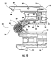
図2~図10を参照すると、ワンド110はまた、第1及び第2の係止機構200、202並びに単一のアクチュエータ204を含む(第2の係止機構202は、図9及び図10に最も良く示されている)。第1の係止機構200は、第1及び第2のワンドセグメント140、150を拡張位置(例えば、図2)に係止(例えば、固定)するように構成されており、一方で、第2の係止機構202(図9及び図10に最も良く示される)は、第1及び第2のワンドセグメント140、150をストレージ構成(例えば、図4)に係止(例えば、固定)するように構成されている。任意で、第2の係止機構202は、第1及び第2のワンドセグメント140、150を中間構成に係止(例えば、固定)するように構成され得る。本明細書で使用される場合、中間構成は、第1及び第2のワンドセグメント140、150が、拡張構成(すなわち、0の関節角度)とストレージ構成(例えば、約180の関節角度)との間の関節角度まで接合部141の周りを回動する構成を指すことが意図される。
2-10, the wand 110 also includes first and
第1の係止機構200の一実施例を図2~図8に示す。特に、係止機構200は、(係止アーム206が第2のヒンジ部材153に回動可能に連結され得ることが理解されるべきであるが)回動点207の周りで第1のヒンジ部材151に回動可能に連結され得る、係止アーム、ラッチ、又はこれに類するもの206(図5~図8で最も良く分かる)を含み得る。係止アーム206は、第1及び第2のヒンジ部材151、153を所望の位置(例えば、図2に示すような拡張構成)に固定するために、第2のヒンジ部材153内に形成された対応する係止くぼみ210(図6で最も良く分かる)の一部分とラッチする係止歯止め、フック、又はこれに類するもの208(図7及び図8で良く分かる)を含み得る。係止アーム206は、第2のヒンジ部材153に回動可能に連結され得、係止くぼみ210は、第1のヒンジ部材151内に形成され得ることが理解されるべきである。
One embodiment of a
任意選択で、係止アーム206は、係止アーム206をデフォルトの係止位置に付勢する付勢装置(例えば、ばね又はこれに類するものなどであるがこれに限定されない、明確にするために図示せず)を含み得る。デフォルトの係止位置は、係止アーム206が拡張構成にあるときに係止くぼみ210内に固定される位置に対応し得る。
Optionally, the locking
任意選択で、係止アームガード212(例えば、図5、図7及び図8に概略的に示されるような)は、係止アーム206の遠位端の周りに延在し得、係止アーム側壁214(例えば、図6に概略的に示されるような)は、係止くぼみ210の少なくとも一部分の周りに延在し得る。係止アームガード212は、拡張構成にあるときに、係止アーム側壁214内に少なくとも部分的に受容されるように構成され得る。係止アームガード212及び係止アーム側壁214は、拡張構成にあるときにワンド110のねじり剛性を増加させ得る。
Optionally, a locking arm guard 212 (e.g., as shown diagrammatically in FIGS. 5, 7, and 8) may extend around the distal end of the
単一のアクチュエータ204は、ボタン又はタブ216(例えば、図5を参照)を含み得る。単一のアクチュエータ204は、接合部141と比較してワンド110の反対側に配置され得る。少なくとも1つの実施例では、ボタン216は、係止アーム206から、例えば、回動点207の反対側に延在している。拡張構成から代替構成までヒンジ部材151、153(及び拡張によって、第1及び第2のワンドセグメント140、150)を移動させるために、ユーザは、付勢装置に対してボタン216を内側に押す(例えば、付勢する)ことができ、これにより、係止アーム206が回動点207の周りを回動して、かつ係止くぼみ210から解放され、それによって、ユーザは、ヒンジ部材151、153並びに第1及び第2のワンドセグメント140、150を拡張構成から別の構成に移動させることができる。
The
図9及び図10を参照すると、第2の係止機構202の一実施例が示されている。第2の係止機構202は、第1の係止機構200と同じ単一のアクチュエータ204によってトリガーされ得る。特に、第2の係止機構202は、ロッド300、摺動レバー302、プランジャ304、及び1つ以上のプランジャくぼみ306を含み得る。係止解除状態(例えば、図9に示すような)にあるときに、プランジャ304は、プランジャくぼみ306内に配置されない。例えば、プランジャ304は、係止解除状態にあるときに、ワンド110のヒンジ151(例えば、第1及び/又は第2のヒンジ部材151、153によって形成されるくぼみ)に配置され得る。これに対して、係止位置(例えば、図10に示すような)にあるときに、プランジャ304は、プランジャくぼみ306内に少なくとも部分的に受容され、それによって、第2のヒンジ部材153に対する第1のヒンジ部材151(及び拡張によって、第1及び第2のワンドセグメント140、150)の位置を係止(すなわち、固定)する。
9 and 10, one embodiment of the
第2の係止部材202を係止状態から解放するために、ユーザは、ボタン216を付勢装置に対して内側に押す(例えば、付勢する)ことができ、これにより、ロッド300を矢印Aの方向に(例えば、接合部141と比較してワンド110の反対側に向かって略直線的に)移動させる。ロッド300は、ワンド110の流体通路の周りにロッド300が概ね延在することを可能にするように、略弓形を有し得る。ロッド300の移動は、第1及び第2のヒンジ部材151、153によって制限され得る。ロッド300の第1の端領域308は、単一のアクチュエータ204と係合し得る。例えば、ロッド300の第1の端領域308は、ボタン216の後側310と接触し得る。したがって、ユーザによるボタン216の移動(例えば、矢印Bの方向における)は、ロッド300を矢印Aの方向に移動させ得る。ロッド300の第2の端領域312(例えば、第1の端領域308の概ね反対側)は、摺動レバー302の第1の端領域318上の対応するカム面316と係合(例えば、接触)するように構成されたカム面314を含み得る。カム面314、316は、方向Aでのロッド300の移動を矢印Cの方向での摺動レバー302の移動に変換するように構成され得る。図示した実施例では、方向Cは、拡張構成にあるときにワンド110の長手方向軸に略平行であり得るが、これは、そうであると具体的に主張されない限り、本開示を限定するものではない。摺動ロッド302の移動は、1つ以上のスロット及びポスト320によって制約され得る。
To release the
摺動レバー302の第2の端領域322は、プランジャ304を選択的に係合(例えば、接触)するように構成されたフィンガ324を含み得る。摺動レバー302は、矢印Cの反対方向に(例えば、1つ以上のばね又はこれに類するもの301によって)付勢され得る。したがって、摺動レバー302は、概して、プランジャ304と接触しないように付勢され得る。少なくとも1つの実施例では、摺動レバー302はプランジャくぼみ306から概ね離れるように付勢され得る。プランジャくぼみ306は、第1のヒンジ部材151内に形成され得る。
The
プランジャ304は、第2のヒンジ部材153内に形成され得、第2のヒンジ部材153から略半径方向外側に(例えば、1つ以上のばね又はこれに類するもの303によって)付勢され得る。接合部141の回動軸の周りの第1のヒンジ部材151に対する第2のヒンジ部材153の回転は、プランジャ304をまた接合部141の回動軸の周りに回転させる。プランジャ304の遠位端は、第1のヒンジ部材151内に形成された溝又はスロット内で摺動し得る。プランジャ304の遠位端がプランジャくぼみ306と整列すると、プランジャばね303は、プランジャ304の遠位端をプランジャくぼみ306内に付勢し、それによって、図10に全体的に示すように、第1及び第2のヒンジ部材151、153をストレージ構成に係止する(例えば、固定する)。第2のヒンジ部材153内のプランジャ304の位置及び第1のヒンジ部材151内のプランジャくぼみ306の位置は、ストレージ構成においてそれらが互いに整列するように配設され得る。
The
第2の係止機構202を解放(例えば、係止解除)するために、ユーザは、ボタン216を付勢装置に対して内側に押す(例えば、付勢する)ことができ、これにより、ロッド300を矢印Aの方向に移動させ、それによって、摺動レバー302を矢印Cの方向に移動させ、その結果、フィンガは、プランジャ304の遠位端に接触し、プランジャ304をプランジャくぼみ306から(例えば、概して図10の矢印Dの方向に)押し出す。プランジャ304がプランジャくぼみ306から押し出されると、第1及び第2のヒンジ部材151、153は、係止解除され、互いに対して移動することができる。
To release (e.g., unlock) the
当然のことながら、第1のヒンジ部材151は、代替的な構成/位置に対応する追加的なプランジャくぼみを含み得る。例えば、1つの代替的な構成/位置は、拡張構成とストレージ構成との間の位置構成/位置に対応し得る。別の方法として(又は追加的に)、代替的な構成/位置は、拡張された代替的な構成に対応し得る。
Of course, the
図11及び図12を参照すると、接合部141は、1つ以上の支持リング191を任意で含み得る。支持リング191は、例えば、ヒンジ155の周りで、接合部141内に一体化され得る。支持リング191は、接合部141の強度を増加させ得る。少なくとも1つの実施例では、支持リング191は、接合部141のねじり剛性を増加させ、かつ/又はヒンジ部材151、153同士の分離を防止し得る。支持リング191は、ストレージ係止機構の周りに統合された鋼リングを含み得る。一部の実施例では、支持リング191は、ヒンジ151の周りに少なくとも部分的に延在し得る。示されるように、支持リング191は、支持リング191が互いに近接して配置されるが、離間するように構成されている2つの端193を有する、係止リング及び/又はC字形状の構成を含み得る。2つの端193は、支持リング191が(示されるように)それ自体と重ならないように、又は支持リング191がそれ自体と重なるように構成され得る。支持リング191はまた、端部を持たない環状リングを含み得る。
11 and 12, the joint 141 may optionally include one or more support rings 191. The support rings 191 may be integrated into the joint 141, for example, around the
本発明の原理は本明細書に記載されるが、本記述は、例としてのみ行われ、本発明の範囲に限定されないことは、当業者によって理解されるべきである。他の実施形態は、本明細書に示され、かつ記述される例示的な実施形態に加えて、本発明の範囲内で意図される。表面クリーニング機器及び/又は撹拌器は、本明細書に含まれる特徴のうちの任意の1つ以上を具体化してもよく、またこの特徴は、任意の特定の組み合わせ又は下位組み合わせで使用され得ることが当業者によって理解されるであろう。当業者による修正及び置換は、本発明の範囲内であると考えられ、特許請求の範囲によるのを除いて限定されるべきではない。 While the principles of the present invention are described herein, it should be understood by those skilled in the art that this description is made by way of example only and is not intended to limit the scope of the present invention. Other embodiments are contemplated within the scope of the present invention in addition to the exemplary embodiments shown and described herein. It will be understood by those skilled in the art that a surface cleaning device and/or agitator may embody any one or more of the features contained herein, and that the features may be used in any particular combination or subcombination. Modifications and substitutions made by those skilled in the art are considered to be within the scope of the present invention and should not be limited except as by the claims.
Claims (17)
空気通路の第1及び第2の部分を画定する、第1及び第2のワンドセグメントと、
前記第1のワンドセグメントの端に位置する第1のヒンジ部材と、前記第2のワンドセグメントの端に位置する第2のヒンジ部材と、第1のヒンジ部材及び第2のヒンジ部材を回動可能に連結するヒンジと、を備える、曲げ可能なワンド接合部であって、ヒンジは前記第1のワンドセグメント及び前記第2のワンドセグメントを複数の構成において回動可能に接続するように構成されており、前記複数の構成が、
前記第1のワンドセグメント及び前記第2のワンドセグメントが使用中に互いに対して直線状である拡張構成と、
前記第1のワンドセグメント及び前記第2のワンドセグメントが使用中に互いに対して曲げられるストレージ構成と、を含む、曲げ可能なワンド接合部と、
前記第1のワンドセグメントと前記第2のワンドセグメントとの間にあって、前記空気通路の可撓性の空気部分を画定し、かつ前記第1のヒンジ部材及び前記第2のヒンジ部材が前記ヒンジの周りを回動するときに屈曲するように構成された可撓性の管と、
前記第1のヒンジ部材に回動可能に連結されたフック又は歯止めを含む係止アームを備える、第1の係止機構であって、ワンドが前記拡張構成に配置されて、前記第1及び第2のワンドセグメントを前記拡張構成に係止するときに、前記フック又は歯止めが前記第2のヒンジ部材に形成された係止くぼみ内に少なくとも部分的に受容されるように構成されている、第1の係止機構と、
前記第1及び第2のワンドセグメントを前記ストレージ構成に係止するように構成された第2の係止機構であって、前記第2の係止機構が、第1の端領域及び第2の端領域を有するロッド、ロッドの第2の端領域と係合する第1の端領域を有する摺動レバー、摺動レバーの第2の端領域において摺動レバーと選択的に係合するプランジャ、及びプランジャの遠位端と整列するプランジャくぼみを備え、ワンドが前記ストレージ構成に配置されたときに、前記プランジャが前記プランジャくぼみ内に少なくとも部分的に受容されるように構成されている、第2の係止機構と、
前記拡張構成及び前記ストレージ構成の両方において、前記第1及び第2のワンドセグメントを係止解除するための単一のアクチュエータと、を備えており、
ワンドが前記拡張構成に配置されるときに、前記単一のアクチュエータを押下することにより、前記係止アームが回動し、かつ前記フック又は歯止めが前記係止くぼみから取り外されてワンドを係止解除し、
ワンドが前記ストレージ構成に配置されるときに、前記単一のアクチュエータを押下することにより、前記ロッドの第1の端領域が該アクチュエータと係合して該ロッドを第1の方向に移動させ、次に前記摺動レバーを第1の方向とは異なる第2の方向に移動させて該摺動レバーの第2の端領域を前記プランジャの遠位端に係合させることで、前記プランジャを前記プランジャくぼみから押し出してワンドを係止解除する、ワンド。 1. A wand for a vacuum cleaner , comprising:
first and second wand segments defining first and second portions of an air passage;
1. A bendable wand joint comprising: a first hinge member located at an end of the first wand segment ; a second hinge member located at an end of the second wand segment ; and a hinge pivotally connecting the first hinge member and the second hinge member , the hinge being configured to pivotally connect the first wand segment and the second wand segment in a plurality of configurations, the plurality of configurations being:
an extended configuration in which the first wand segment and the second wand segment are linear relative to one another during use;
a storage configuration in which the first wand segment and the second wand segment are bent relative to one another during use;
a flexible tube between the first and second wand segments, the flexible tube defining a flexible air portion of the air passageway and configured to bend as the first and second hinge members pivot about the hinge;
a first locking mechanism comprising a locking arm including a hook or pawl pivotally coupled to the first hinge member, the hook or pawl configured to be at least partially received within a locking recess formed in the second hinge member when the wand is disposed in the extended configuration to lock the first and second wand segments in the extended configuration;
a second locking mechanism configured to lock the first and second wand segments in the storage configuration, the second locking mechanism comprising a rod having a first end region and a second end region , a sliding lever having a first end region that engages with the second end region of the rod , a plunger selectively engaging the sliding lever at the second end region of the sliding lever , and a plunger recess aligned with a distal end of the plunger , the plunger configured to be at least partially received within the plunger recess when the wand is disposed in the storage configuration;
a single actuator for unlocking the first and second wand segments in both the extended and stored configurations;
when the wand is disposed in the extended configuration, depressing the single actuator causes the locking arm to pivot and the hook or pawl to disengage from the locking recess to unlock the wand;
When the wand is placed in the storage configuration, depressing the single actuator causes a first end region of the rod to engage with the actuator and move the rod in a first direction, and then moving the sliding lever in a second direction different from the first direction to cause a second end region of the sliding lever to engage a distal end of the plunger , thereby pushing the plunger out of the plunger recess and unlocking the wand.
前記第2のヒンジ部材から外向きに、かつ前記係止くぼみの周りに少なくとも部分的に延在している、係止アーム側壁であって、係止アーム側壁が、前記係止アームガードの少なくとも一部分を受容するように構成されている、係止アーム側壁と、を更に備える、請求項1に記載のワンド。 a locking arm guard extending from the first hinge member around a distal end of the locking arm;
2. The wand of claim 1, further comprising a locking arm sidewall extending outwardly from the second hinge member and at least partially around the locking recess, the locking arm sidewall configured to receive at least a portion of the locking arm guard.
空気通路の第1及び第2の部分を画定する、第1及び第2のワンドセグメントと、
前記第1のワンドセグメントの端に位置する第1のヒンジ部材と、前記第2のワンドセグメントの端に位置する第2のヒンジ部材と、第1のヒンジ部材及び第2のヒンジ部材を回動可能に連結するヒンジと、を備える、曲げ可能なワンド接合部であって、ヒンジは前記第1のワンドセグメント及び前記第2のワンドセグメントを少なくとも第1の構成及び第2の構成で回動可能に接続するように構成されており、前記第1の構成が拡張位置に対応している、曲げ可能なワンド接合部と、
前記第1のワンドセグメントと前記第2のワンドセグメントとの間に連結された可撓性の管と、
前記第1及び第2のワンドセグメントを前記第1の構成に係止するための第1の係止機構と、
前記第1及び第2のワンドセグメントを前記第2の構成に係止するように構成された第2の係止機構であって、前記第2の係止機構が、第1の端領域及び第2の端領域を有するロッド、ロッドの第2の端領域と係合する第1の端領域を有する摺動レバー、摺動レバーの第2の端領域において摺動レバーと選択的に係合するプランジャ、及びプランジャの遠位端と整列するプランジャくぼみを備え、ワンドが前記第2の構成に配置されたときに、前記プランジャが前記プランジャくぼみ内に少なくとも部分的に受容されるように構成されている、第2の係止機構と、
前記第1の構成及び前記第2の構成の両方において、前記第1及び第2のワンドセグメントを係止解除するための単一のアクチュエータと、を備えており、
ワンドが前記第2の構成に配置されるときに、前記単一のアクチュエータを押下することにより、前記ロッドの第1の端領域が該アクチュエータと係合して該ロッドを第1の方向に移動させ、次に前記摺動レバーを第1の方向とは異なる第2の方向に移動させて該摺動レバーの第2の端領域を前記プランジャの遠位端に係合させることで、前記プランジャを前記プランジャくぼみから押し出して前記第1及び第2のワンドセグメントを係止解除する、ワンド。 1. A wand for a vacuum cleaner , comprising:
first and second wand segments defining first and second portions of an air passage;
a bendable wand joint comprising a first hinge member located at an end of the first wand segment , a second hinge member located at an end of the second wand segment , and a hinge pivotally connecting the first hinge member and the second hinge member , the hinge configured to pivotally connect the first wand segment and the second wand segment in at least a first configuration and a second configuration , the first configuration corresponding to an extended position;
a flexible tube connected between the first wand segment and the second wand segment;
a first locking mechanism for locking the first and second wand segments in the first configuration;
a second locking mechanism configured to lock the first and second wand segments in the second configuration, the second locking mechanism comprising a rod having a first end region and a second end region , a sliding lever having a first end region that engages the second end region of the rod , a plunger selectively engaging the sliding lever at the second end region of the sliding lever , and a plunger recess aligned with a distal end of the plunger , the plunger configured to be at least partially received within the plunger recess when the wand is disposed in the second configuration;
a single actuator for unlocking the first and second wand segments in both the first and second configurations;
A wand wherein when the wand is disposed in the second configuration, depressing the single actuator causes a first end region of the rod to engage with the actuator and move the rod in a first direction, and then moving the sliding lever in a second direction different from the first direction to cause a second end region of the sliding lever to engage a distal end of the plunger , thereby pushing the plunger out of the plunger recess and unlocking the first and second wand segments .
第1のヒンジ部材を含む第1のワンドセグメント、及び第2のヒンジ部材を含む第2のワンドセグメントと、
前記第1のヒンジ部材及び前記第2のヒンジ部材を回動可能に連結するとともに、前記第1のワンドセグメント及び前記第2のワンドセグメントを少なくとも第1の構成及び第2の構成で回動可能に接続するように構成されたヒンジであって、前記第1の構成が拡張位置に対応している、ヒンジと、
前記第1のワンドセグメントと第2のワンドセグメントとの間に連結された可撓性の管と、
前記第1及び第2のワンドセグメントを前記第1の構成に係止するように構成された第1の係止部と、
前記第1及び第2のワンドセグメントを前記第2の構成に係止するように構成された第2の係止部であって、第2の係止部が、第1の端領域及び第2の端領域を有するロッド、ロッドの第2の端領域と係合する第1の端領域を有する摺動レバー、摺動レバーの第2の端領域において摺動レバーと選択的に係合するプランジャ、及びプランジャの遠位端と整列するプランジャくぼみを備え、ワンドが前記第2の構成に配置されたときに、前記プランジャが前記プランジャくぼみ内に少なくとも部分的に受容されるように構成されている、第2の係止部と、
前記第1及び第2の係止部の両方を係止解除するように構成された1つのアクチュエータと、を備えており、
ワンドが前記第2の構成に配置されるときに、前記1つのアクチュエータを押下することにより、前記ロッドの第1の端領域が該アクチュエータと係合して該ロッドを第1の方向に移動させ、次に前記摺動レバーを第1の方向とは異なる第2の方向に移動させて該摺動レバーの第2の端領域を前記プランジャの遠位端に係合させることで、前記プランジャを前記プランジャくぼみから押し出して前記第2の係止部を係止解除する、ワンド。 1. A wand for a vacuum cleaner , comprising:
a first wand segment including a first hinge member and a second wand segment including a second hinge member;
a hinge configured to pivotally couple the first hinge member and the second hinge member and to pivotally connect the first wand segment and the second wand segment in at least a first configuration and a second configuration, the first configuration corresponding to an extended position;
a flexible tube connected between the first and second wand segments ;
a first locking portion configured to lock the first and second wand segments in the first configuration;
a second lock configured to lock the first and second wand segments in the second configuration, the second lock comprising a rod having a first end region and a second end region , a sliding lever having a first end region that engages the second end region of the rod , a plunger selectively engaging the sliding lever at the second end region of the sliding lever , and a plunger recess aligned with a distal end of the plunger , the plunger configured to be at least partially received within the plunger recess when the wand is disposed in the second configuration;
and an actuator configured to unlock both the first and second catches,
A wand, wherein when the wand is disposed in the second configuration, depressing one of the actuators causes a first end region of the rod to engage with the actuator and move the rod in a first direction , and then moving the sliding lever in a second direction different from the first direction to cause a second end region of the sliding lever to engage a distal end of the plunger , thereby pushing the plunger out of the plunger recess and unlocking the second locking portion .
Priority Applications (1)
| Application Number | Priority Date | Filing Date | Title |
|---|---|---|---|
| JP2025008906A JP2025061582A (en) | 2021-06-18 | 2025-01-22 | Vacuum cleaner wand |
Applications Claiming Priority (3)
| Application Number | Priority Date | Filing Date | Title |
|---|---|---|---|
| US202163212412P | 2021-06-18 | 2021-06-18 | |
| US63/212,412 | 2021-06-18 | ||
| PCT/US2022/034078 WO2022266495A1 (en) | 2021-06-18 | 2022-06-17 | Vacuum cleaning device with foldable wand to provide storage configuration |
Related Child Applications (1)
| Application Number | Title | Priority Date | Filing Date |
|---|---|---|---|
| JP2025008906A Division JP2025061582A (en) | 2021-06-18 | 2025-01-22 | Vacuum cleaner wand |
Publications (2)
| Publication Number | Publication Date |
|---|---|
| JP2024521520A JP2024521520A (en) | 2024-05-31 |
| JP7625728B2 true JP7625728B2 (en) | 2025-02-03 |
Family
ID=84489763
Family Applications (2)
| Application Number | Title | Priority Date | Filing Date |
|---|---|---|---|
| JP2023578018A Active JP7625728B2 (en) | 2021-06-18 | 2022-06-17 | Vacuum cleaner wand |
| JP2025008906A Pending JP2025061582A (en) | 2021-06-18 | 2025-01-22 | Vacuum cleaner wand |
Family Applications After (1)
| Application Number | Title | Priority Date | Filing Date |
|---|---|---|---|
| JP2025008906A Pending JP2025061582A (en) | 2021-06-18 | 2025-01-22 | Vacuum cleaner wand |
Country Status (7)
| Country | Link |
|---|---|
| US (2) | US12053141B2 (en) |
| EP (1) | EP4355187B1 (en) |
| JP (2) | JP7625728B2 (en) |
| KR (2) | KR20250073494A (en) |
| CN (2) | CN218960627U (en) |
| AU (2) | AU2022294097B2 (en) |
| WO (1) | WO2022266495A1 (en) |
Families Citing this family (15)
| Publication number | Priority date | Publication date | Assignee | Title |
|---|---|---|---|---|
| WO2021207139A1 (en) | 2020-04-06 | 2021-10-14 | Sharkninja Operating Llc | Allergen reduction device |
| GB2608761B (en) | 2020-04-13 | 2024-03-06 | Sharkninja Operating Llc | Caster locking arrangement and surface cleaning device implementing same |
| WO2022026728A1 (en) | 2020-07-29 | 2022-02-03 | Sharkninja Operating Llc | Nozzle for a surface treatment apparatus and a surface treatment apparatus having the same |
| WO2022221274A1 (en) | 2021-04-12 | 2022-10-20 | Sharkninja Operating Llc | Robotic cleaner |
| US12339324B2 (en) | 2021-04-23 | 2025-06-24 | Sharkninja Operating Llc | Determining state of charge for battery powered devices including battery powered surface treatment apparatuses |
| USD1089916S1 (en) * | 2021-06-04 | 2025-08-19 | Sharkninja Operating Llc | Vacuum wand |
| US20230043567A1 (en) | 2021-08-03 | 2023-02-09 | Sharkninja Operating Llc | Surface cleaning device with odor management |
| US12433461B2 (en) | 2022-07-05 | 2025-10-07 | Sharkninja Operating Llc | Vacuum cleaner |
| US12376722B2 (en) | 2021-08-13 | 2025-08-05 | Sharkninja Operating Llc | Robotic cleaner |
| EP4398781A4 (en) | 2021-09-07 | 2025-10-15 | Sharkninja Operating Llc | CLEANING ROBOT |
| WO2023081352A1 (en) | 2021-11-05 | 2023-05-11 | Sharkninja Operating Llc | Surface cleaning device with odor control |
| US12329350B2 (en) | 2022-05-09 | 2025-06-17 | Sharkninja Operating Llc | Robotic cleaner |
| USD1058075S1 (en) * | 2022-06-24 | 2025-01-14 | Sharkninja Operating Llc | Vacuum cleaner |
| FR3141053B1 (en) * | 2022-10-21 | 2024-10-25 | Seb Sa | Vacuum duct equipped with an articulation device |
| WO2024216566A1 (en) | 2023-04-20 | 2024-10-24 | Sharkninja Operating Llc | System and method for detecting walls or objects within a specific proximity of a vacuum floor nozzle |
Citations (4)
| Publication number | Priority date | Publication date | Assignee | Title |
|---|---|---|---|---|
| JP2010082166A (en) | 2008-09-30 | 2010-04-15 | Toshiba Corp | Vacuum cleaner |
| CN108542308A (en) | 2018-06-11 | 2018-09-18 | 苏州诚河清洁设备有限公司 | Pipe coupling component for surface cleaning apparatus |
| JP2018535703A (en) | 2015-10-22 | 2018-12-06 | シャークニンジャ オペレーティング エルエルシー | Vacuum cleaner with foldable tube providing storage form |
| CN210300851U (en) | 2018-12-29 | 2020-04-14 | 尚科宁家(中国)科技有限公司 | Dust collector |
Family Cites Families (92)
| Publication number | Priority date | Publication date | Assignee | Title |
|---|---|---|---|---|
| US1759947A (en) | 1924-01-14 | 1930-05-27 | Delco Light Co | Domestic appliance |
| US2074042A (en) | 1935-02-09 | 1937-03-16 | Bank Edward Carl | Swivel connection for vacuum cleaner nozzles |
| DE742606C (en) | 1940-10-05 | 1943-12-08 | Fisker & Nielsen As | Vacuum cleaner mouthpiece |
| US3163707A (en) | 1962-12-27 | 1964-12-29 | Ralph E Darling | Non-stretch flexible tube with conductors therein |
| US3306634A (en) | 1963-02-07 | 1967-02-28 | Pul Vac Inc | Articulate joint |
| US3245698A (en) | 1963-11-04 | 1966-04-12 | Westinghouse Electric Corp | Latching means |
| US3314039A (en) | 1965-03-09 | 1967-04-11 | Dayco Corp | Vacuum cleaner connector |
| US3451495A (en) | 1966-05-17 | 1969-06-24 | United Shoe Machinery Corp | Power devices having reversible drive |
| SE424409B (en) | 1975-12-04 | 1982-07-19 | Coral Sas | DEVICE FOR LOCAL EXTENSION OF GASES, Fumes AND SIMILAR |
| JPS562168U (en) | 1979-06-12 | 1981-01-09 | ||
| US4393536A (en) | 1982-01-25 | 1983-07-19 | Tapp Ruel W | Dual mode vacuum cleaner |
| IT1181150B (en) | 1984-12-21 | 1987-09-23 | Arno Drechsel | ARTICULATED TELESCOPIC JOINT FITTING, FOR REGULATION OF THE INCLINATION OF THE SPRAY OF THE SPRAYERS IN GENERAL, AND SPRINKLER EQUIPPED WITH THE FITTING |
| US4644605A (en) | 1985-03-25 | 1987-02-24 | Bissell Inc. | Stick vacuum cleaner |
| DE3737295A1 (en) | 1987-11-04 | 1989-05-18 | Krause Werk Gmbh & Co Kg | JOINT FOR LADDERS |
| US5107567A (en) | 1990-03-01 | 1992-04-28 | White Consolidated Industries, Inc. | Stick type vacuum cleaner with a dirt cup secured by a finger-operated latch |
| US5331715A (en) | 1992-06-04 | 1994-07-26 | Matsushita Floor Care Company | Two motor upright vacuum cleaner |
| JP3517935B2 (en) | 1993-06-02 | 2004-04-12 | 株式会社日立製作所 | Bending equipment |
| SE9600650A0 (en) | 1996-02-22 | 1997-08-23 | Vikström Rune | Device for vacuum cleaner |
| US5810408A (en) | 1996-06-07 | 1998-09-22 | Armstrong; Jeffrey L. | Ergonomically efficient tool |
| JP3424151B2 (en) | 1997-01-29 | 2003-07-07 | 三菱電機株式会社 | Vacuum cleaner floor nozzle |
| SE509150C2 (en) | 1997-04-07 | 1998-12-07 | Electrolux Ab | The vacuum cleaner |
| DE19843973B4 (en) | 1998-01-16 | 2015-11-05 | BSH Hausgeräte GmbH | Hose arrangement for a vacuum cleaner |
| KR100239165B1 (en) | 1998-03-16 | 2000-01-15 | 배길성 | Apparatus for folding extention pipe of vacuum cleaner |
| US6015298A (en) | 1998-06-09 | 2000-01-18 | Truplast Konststofftechnik Gmbh | Vacuum-cleaner hose with electrical conductors |
| US5996175A (en) | 1998-07-23 | 1999-12-07 | Fusco; Edward | Adjustable vacuum handle construction |
| US6345408B1 (en) | 1998-07-28 | 2002-02-12 | Sharp Kabushiki Kaisha | Electric vacuum cleaner and nozzle unit therefor |
| JP2000300484A (en) | 1999-04-20 | 2000-10-31 | Sanyo Electric Co Ltd | Vacuum cleaner |
| AU4303899A (en) | 1999-04-30 | 2000-11-17 | Johan Bystrom | A joint device |
| JP2001269294A (en) | 2000-03-23 | 2001-10-02 | Sharp Corp | Electric vacuum cleaner |
| SE516615C2 (en) | 2000-06-21 | 2002-02-05 | Johan Adolf Bystroem | Bendable joint |
| KR100389289B1 (en) | 2000-09-22 | 2003-06-27 | 주식회사 대우일렉트로닉스 | Vacuum cleaner |
| US6695352B2 (en) | 2001-01-29 | 2004-02-24 | Lg Electronics Inc. | Extension tube in vacuum cleaner |
| SE519073C2 (en) | 2001-05-31 | 2003-01-07 | Electrolux Ab | Pipe shaft for a vacuum cleaner |
| ITMO20010215A1 (en) | 2001-11-13 | 2003-05-13 | Next At Srl | ARTICULATED JOINT FOR RIGID PIPES SUPPLIED TO HOUSEHOLD APPLIANCES |
| KR20030072000A (en) | 2002-03-05 | 2003-09-13 | 삼성광주전자 주식회사 | Articulated joint assembly for vacuum cleaner and vacuum cleaner having the same |
| GB0228153D0 (en) | 2002-12-03 | 2003-01-08 | Techtronic Ind Co Ltd | Suction cleaners |
| US20040134022A1 (en) | 2003-01-10 | 2004-07-15 | Royal Manufacturing Co. | Bagless stick type vacuum cleaner |
| US7194784B2 (en) | 2003-06-24 | 2007-03-27 | Panasonic Corporation Of North America | Floor cleaning apparatus with pivotal handle |
| KR100474081B1 (en) | 2003-06-26 | 2005-03-14 | 삼성광주전자 주식회사 | A vacuum cleaner having a removable main body and one body frame assembly |
| KR100474083B1 (en) | 2003-06-26 | 2005-03-14 | 삼성광주전자 주식회사 | A vacuum cleaner for many purposes |
| US20050022338A1 (en) | 2003-07-28 | 2005-02-03 | Muhlenkamp Eric E. | Electrified extension hose for vacuum cleaner |
| US7226302B2 (en) | 2003-09-22 | 2007-06-05 | Scotech Systems Inc. | Vacuum cleaner current-carrying hose connection system |
| ITMO20030277A1 (en) | 2003-10-09 | 2005-04-10 | T P A Impex Spa | ASPIRATING ELECTRIC APPLIANCES WITH MANEUVERING HANDLE. |
| KR100572891B1 (en) | 2003-10-20 | 2006-04-24 | 삼성광주전자 주식회사 | Refractive extension tube of vacuum cleaner |
| KR100563458B1 (en) | 2003-12-02 | 2006-03-23 | 삼성광주전자 주식회사 | Refractive extension tube of vacuum cleaner |
| KR20050053054A (en) | 2003-12-02 | 2005-06-08 | 삼성광주전자 주식회사 | Extension pipe having joint for vacuum cleaner |
| KR20050058163A (en) | 2003-12-11 | 2005-06-16 | 엘지전자 주식회사 | An up right type vacuum cleaner |
| KR20050059573A (en) | 2003-12-15 | 2005-06-21 | 삼성광주전자 주식회사 | Extension pipe having joint for vacuum cleaner |
| KR100670595B1 (en) | 2004-03-24 | 2007-01-17 | 삼성광주전자 주식회사 | Upright cleaner |
| JP2006192248A (en) | 2005-01-14 | 2006-07-27 | Samsung Kwangju Electronics Co Ltd | Refraction extension tube of vacuum cleaner |
| WO2006078580A2 (en) | 2005-01-18 | 2006-07-27 | Electrolux Home Care Products, Ltd | Vacuum cleaner with collapsible handle |
| EP1764021A1 (en) | 2005-09-16 | 2007-03-21 | IMETEC S.p.A. | Extension tube for domestic cleaning devices and domestic cleaning device comprising such an extension tube |
| DE102005044428B4 (en) | 2005-09-16 | 2011-08-18 | Hans Lingl Anlagenbau und Verfahrenstechnik GmbH & Co. KG, 86381 | Device for cutting a strand of plastically deformable material, in particular clay, with a holder which can be moved by at least one drive element for at least one cutting wire |
| KR100730948B1 (en) | 2005-09-30 | 2007-06-22 | 주식회사 대우일렉트로닉스 | Refractive extension tube of vacuum cleaner |
| GB2433022A (en) | 2005-12-08 | 2007-06-13 | Hoover Ltd | Vacuum cleaner with folding handle |
| SE529538C2 (en) | 2006-01-29 | 2007-09-04 | Lennart Olsson | Vacuum cleaner tubes comprising an inner and an outer relative to each other telescopic parts |
| DE102006033021A1 (en) | 2006-07-17 | 2008-01-24 | Vorwerk & Co. Interholding Gmbh | Electric vacuum cleaner with a basic unit and an attachment |
| ITMI20061436A1 (en) | 2006-07-21 | 2008-01-22 | Colbachini Spa | PERFECT TYPE OF FLEXIBLE HOSE, WITH INCORPORATED ELECTRICAL CABLE. |
| CN201070328Y (en) | 2006-12-29 | 2008-06-11 | 光荣电业有限公司 | floor cleaning device |
| US20080174105A1 (en) | 2007-01-22 | 2008-07-24 | Hyatt Andrew C | Flexible vacuum cleaner hose coupling |
| DE602007010720D1 (en) | 2007-02-12 | 2011-01-05 | Black & Decker Inc | vacuum cleaner |
| DE102007036524A1 (en) | 2007-08-02 | 2009-02-05 | Vorwerk & Co. Interholding Gmbh | Front nozzle e.g. for vacuum cleaner, has suction channel which connects from orifice and length of channel has openings which can be shut with shutter parts |
| US8296901B2 (en) * | 2008-01-24 | 2012-10-30 | Euro-Pro Operating Llc | Reconfigurable airflow wand |
| US20100229315A1 (en) * | 2009-03-12 | 2010-09-16 | Euro-Pro Operating Llc | Handle for surface cleaning apparatus |
| CA2674376A1 (en) | 2009-03-13 | 2010-09-13 | G.B.D. Corp. | Surface cleaning apparatus with different cleaning configurations |
| US8813297B2 (en) | 2010-03-12 | 2014-08-26 | Euro-Pro Operating Llc | Floor cleaning device |
| GB2488368B (en) | 2011-02-28 | 2013-03-20 | Dyson Technology Ltd | A cleaner head for a surface treating appliance |
| US8984701B2 (en) | 2011-08-10 | 2015-03-24 | Kevin Alan Tussy | Flexible handle for cleaning tools |
| JP2013070839A (en) | 2011-09-28 | 2013-04-22 | Hitachi Appliances Inc | Vacuum cleaner |
| JP5880189B2 (en) | 2012-03-22 | 2016-03-08 | 三菱電機株式会社 | Electric vacuum cleaner |
| JP2013192869A (en) | 2012-03-22 | 2013-09-30 | Mitsubishi Electric Corp | Vacuum cleaner |
| JP2013192880A (en) | 2012-03-22 | 2013-09-30 | Mitsubishi Electric Corp | Vacuum cleaner |
| JP2013198701A (en) | 2012-03-26 | 2013-10-03 | Toshiba Corp | Vacuum cleaner and attachment thereof |
| US9125538B2 (en) | 2012-07-27 | 2015-09-08 | Techtronic Floor Care Technology Limited | Pivoting handle for a surface cleaning device |
| JP2014045870A (en) | 2012-08-30 | 2014-03-17 | Mitsubishi Electric Corp | Cleaning tool and vacuum cleaner using the cleaning tool |
| DE102012112532A1 (en) | 2012-12-18 | 2014-06-18 | Miele & Cie. Kg | Upright vacuum cleaner has accessory hose connected pivotally with vacuum cleaner by rotatable connection piece, where connection piece acts as valve for air path switching from base unit into dust collecting container |
| US9456721B2 (en) | 2013-02-28 | 2016-10-04 | Omachron Intellectual Property Inc. | Surface cleaning apparatus |
| US9215960B2 (en) | 2013-02-28 | 2015-12-22 | Omachron Intellectual Property Inc. | Surface cleaning apparatus |
| JP6518933B2 (en) | 2014-08-06 | 2019-05-29 | パナソニックIpマネジメント株式会社 | Suction tool and vacuum cleaner using the same |
| JP2016112076A (en) | 2014-12-12 | 2016-06-23 | 株式会社東芝 | Stick-type vacuum cleaner |
| USD810369S1 (en) | 2015-03-26 | 2018-02-13 | Samsung Electronics Co., Ltd. | Cleaner |
| JP6579814B2 (en) | 2015-06-12 | 2019-09-25 | 東芝ライフスタイル株式会社 | Suction port and vacuum cleaner |
| GB2542423B (en) | 2015-09-21 | 2018-01-24 | Dyson Technology Ltd | Handle Assembly For A Vacuum Cleaner |
| CN105581730B (en) | 2016-02-26 | 2017-11-21 | 苏州爱建电器有限公司 | The steering knuckle and hand held cleaner of hand held cleaner |
| GB2549148B (en) | 2016-04-08 | 2018-08-15 | Dyson Technology Ltd | A wand and hose assembly for a vacuum cleaner |
| KR102321633B1 (en) * | 2016-11-21 | 2021-11-05 | 삼성전자주식회사 | cleaner and cleaning device having the same |
| DE202017002073U1 (en) * | 2017-04-20 | 2017-06-29 | Mediashop Holding Gmbh | vacuum cleaner |
| USD836865S1 (en) * | 2017-05-05 | 2018-12-25 | Sharkninja Operating Llc | Adjustable wand for a vacuum cleaner |
| USD892420S1 (en) * | 2018-08-03 | 2020-08-04 | Sharkninja Operating Llc | Adjustable wand for a vacuum cleaner |
| US11051668B2 (en) * | 2018-05-25 | 2021-07-06 | Sharkninja Operating Llc | Vacuum cleaner having reconfigurable weight distribution |
| CN210169955U (en) * | 2018-12-29 | 2020-03-24 | 尚科宁家(中国)科技有限公司 | a vacuum cleaner |
| CN110306923B (en) * | 2019-08-09 | 2023-10-31 | 福州大学 | Driving lever type multi-clamping hinge mechanism and application thereof |
-
2022
- 2022-06-17 JP JP2023578018A patent/JP7625728B2/en active Active
- 2022-06-17 CN CN202221529589.0U patent/CN218960627U/en active Active
- 2022-06-17 CN CN202280043235.1A patent/CN117615692A/en active Pending
- 2022-06-17 KR KR1020257014919A patent/KR20250073494A/en active Pending
- 2022-06-17 EP EP22825931.3A patent/EP4355187B1/en active Active
- 2022-06-17 WO PCT/US2022/034078 patent/WO2022266495A1/en not_active Ceased
- 2022-06-17 US US17/843,709 patent/US12053141B2/en active Active
- 2022-06-17 KR KR1020247000476A patent/KR102806080B1/en active Active
- 2022-06-17 AU AU2022294097A patent/AU2022294097B2/en active Active
-
2024
- 2024-06-24 US US18/751,878 patent/US20240415352A1/en active Pending
-
2025
- 2025-01-22 JP JP2025008906A patent/JP2025061582A/en active Pending
- 2025-04-29 AU AU2025202992A patent/AU2025202992A1/en active Pending
Patent Citations (4)
| Publication number | Priority date | Publication date | Assignee | Title |
|---|---|---|---|---|
| JP2010082166A (en) | 2008-09-30 | 2010-04-15 | Toshiba Corp | Vacuum cleaner |
| JP2018535703A (en) | 2015-10-22 | 2018-12-06 | シャークニンジャ オペレーティング エルエルシー | Vacuum cleaner with foldable tube providing storage form |
| CN108542308A (en) | 2018-06-11 | 2018-09-18 | 苏州诚河清洁设备有限公司 | Pipe coupling component for surface cleaning apparatus |
| CN210300851U (en) | 2018-12-29 | 2020-04-14 | 尚科宁家(中国)科技有限公司 | Dust collector |
Also Published As
| Publication number | Publication date |
|---|---|
| CA3223222A1 (en) | 2022-12-22 |
| EP4355187A4 (en) | 2025-01-01 |
| KR20240009532A (en) | 2024-01-22 |
| WO2022266495A1 (en) | 2022-12-22 |
| CN117615692A (en) | 2024-02-27 |
| US12053141B2 (en) | 2024-08-06 |
| JP2024521520A (en) | 2024-05-31 |
| AU2025202992A1 (en) | 2025-05-15 |
| US20240415352A1 (en) | 2024-12-19 |
| KR102806080B1 (en) | 2025-05-12 |
| AU2022294097B2 (en) | 2025-01-23 |
| JP2025061582A (en) | 2025-04-10 |
| EP4355187A1 (en) | 2024-04-24 |
| CN218960627U (en) | 2023-05-05 |
| EP4355187B1 (en) | 2026-02-25 |
| AU2022294097A1 (en) | 2024-01-25 |
| US20220400922A1 (en) | 2022-12-22 |
| KR20250073494A (en) | 2025-05-27 |
Similar Documents
| Publication | Publication Date | Title |
|---|---|---|
| JP7625728B2 (en) | Vacuum cleaner wand | |
| JP7227303B2 (en) | A vacuum cleaner with a collapsible tube that provides a storage configuration | |
| JP6129811B2 (en) | Electric vacuum cleaner | |
| CA3223222C (en) | Vacuum cleaning device with foldable wand to provide storage configuration |
Legal Events
| Date | Code | Title | Description |
|---|---|---|---|
| A621 | Written request for application examination |
Free format text: JAPANESE INTERMEDIATE CODE: A621 Effective date: 20240216 |
|
| A871 | Explanation of circumstances concerning accelerated examination |
Free format text: JAPANESE INTERMEDIATE CODE: A871 Effective date: 20240216 |
|
| A131 | Notification of reasons for refusal |
Free format text: JAPANESE INTERMEDIATE CODE: A131 Effective date: 20240514 |
|
| A601 | Written request for extension of time |
Free format text: JAPANESE INTERMEDIATE CODE: A601 Effective date: 20240814 |
|
| A521 | Request for written amendment filed |
Free format text: JAPANESE INTERMEDIATE CODE: A523 Effective date: 20240927 |
|
| TRDD | Decision of grant or rejection written | ||
| A01 | Written decision to grant a patent or to grant a registration (utility model) |
Free format text: JAPANESE INTERMEDIATE CODE: A01 Effective date: 20241224 |
|
| A61 | First payment of annual fees (during grant procedure) |
Free format text: JAPANESE INTERMEDIATE CODE: A61 Effective date: 20250122 |
|
| R150 | Certificate of patent or registration of utility model |
Ref document number: 7625728 Country of ref document: JP Free format text: JAPANESE INTERMEDIATE CODE: R150 |