JP7562977B2 - Vehicle lighting fixtures - Google Patents
Vehicle lighting fixtures Download PDFInfo
- Publication number
- JP7562977B2 JP7562977B2 JP2020064053A JP2020064053A JP7562977B2 JP 7562977 B2 JP7562977 B2 JP 7562977B2 JP 2020064053 A JP2020064053 A JP 2020064053A JP 2020064053 A JP2020064053 A JP 2020064053A JP 7562977 B2 JP7562977 B2 JP 7562977B2
- Authority
- JP
- Japan
- Prior art keywords
- light
- lamp
- excitation light
- lens
- substrate
- Prior art date
- Legal status (The legal status is an assumption and is not a legal conclusion. Google has not performed a legal analysis and makes no representation as to the accuracy of the status listed.)
- Active
Links
Images


Classifications
-
- F—MECHANICAL ENGINEERING; LIGHTING; HEATING; WEAPONS; BLASTING
- F21—LIGHTING
- F21S—NON-PORTABLE LIGHTING DEVICES; SYSTEMS THEREOF; VEHICLE LIGHTING DEVICES SPECIALLY ADAPTED FOR VEHICLE EXTERIORS
- F21S43/00—Signalling devices specially adapted for vehicle exteriors, e.g. brake lamps, direction indicator lights or reversing lights
- F21S43/10—Signalling devices specially adapted for vehicle exteriors, e.g. brake lamps, direction indicator lights or reversing lights characterised by the light source
- F21S43/13—Signalling devices specially adapted for vehicle exteriors, e.g. brake lamps, direction indicator lights or reversing lights characterised by the light source characterised by the type of light source
- F21S43/16—Light sources where the light is generated by photoluminescent material spaced from a primary light generating element
-
- B—PERFORMING OPERATIONS; TRANSPORTING
- B60—VEHICLES IN GENERAL
- B60Q—ARRANGEMENT OF SIGNALLING OR LIGHTING DEVICES, THE MOUNTING OR SUPPORTING THEREOF OR CIRCUITS THEREFOR, FOR VEHICLES IN GENERAL
- B60Q1/00—Arrangement of optical signalling or lighting devices, the mounting or supporting thereof or circuits therefor
- B60Q1/26—Arrangement of optical signalling or lighting devices, the mounting or supporting thereof or circuits therefor the devices being primarily intended to indicate the vehicle, or parts thereof, or to give signals, to other traffic
- B60Q1/2607—Arrangement of optical signalling or lighting devices, the mounting or supporting thereof or circuits therefor the devices being primarily intended to indicate the vehicle, or parts thereof, or to give signals, to other traffic comprising at least two indicating lamps
-
- F—MECHANICAL ENGINEERING; LIGHTING; HEATING; WEAPONS; BLASTING
- F21—LIGHTING
- F21S—NON-PORTABLE LIGHTING DEVICES; SYSTEMS THEREOF; VEHICLE LIGHTING DEVICES SPECIALLY ADAPTED FOR VEHICLE EXTERIORS
- F21S43/00—Signalling devices specially adapted for vehicle exteriors, e.g. brake lamps, direction indicator lights or reversing lights
- F21S43/10—Signalling devices specially adapted for vehicle exteriors, e.g. brake lamps, direction indicator lights or reversing lights characterised by the light source
- F21S43/19—Attachment of light sources or lamp holders
-
- F—MECHANICAL ENGINEERING; LIGHTING; HEATING; WEAPONS; BLASTING
- F21—LIGHTING
- F21S—NON-PORTABLE LIGHTING DEVICES; SYSTEMS THEREOF; VEHICLE LIGHTING DEVICES SPECIALLY ADAPTED FOR VEHICLE EXTERIORS
- F21S43/00—Signalling devices specially adapted for vehicle exteriors, e.g. brake lamps, direction indicator lights or reversing lights
- F21S43/20—Signalling devices specially adapted for vehicle exteriors, e.g. brake lamps, direction indicator lights or reversing lights characterised by refractors, transparent cover plates, light guides or filters
- F21S43/235—Light guides
- F21S43/236—Light guides characterised by the shape of the light guide
- F21S43/239—Light guides characterised by the shape of the light guide plate-shaped
-
- F—MECHANICAL ENGINEERING; LIGHTING; HEATING; WEAPONS; BLASTING
- F21—LIGHTING
- F21S—NON-PORTABLE LIGHTING DEVICES; SYSTEMS THEREOF; VEHICLE LIGHTING DEVICES SPECIALLY ADAPTED FOR VEHICLE EXTERIORS
- F21S43/00—Signalling devices specially adapted for vehicle exteriors, e.g. brake lamps, direction indicator lights or reversing lights
- F21S43/20—Signalling devices specially adapted for vehicle exteriors, e.g. brake lamps, direction indicator lights or reversing lights characterised by refractors, transparent cover plates, light guides or filters
- F21S43/235—Light guides
- F21S43/242—Light guides characterised by the emission area
- F21S43/245—Light guides characterised by the emission area emitting light from one or more of its major surfaces
-
- F—MECHANICAL ENGINEERING; LIGHTING; HEATING; WEAPONS; BLASTING
- F21—LIGHTING
- F21S—NON-PORTABLE LIGHTING DEVICES; SYSTEMS THEREOF; VEHICLE LIGHTING DEVICES SPECIALLY ADAPTED FOR VEHICLE EXTERIORS
- F21S43/00—Signalling devices specially adapted for vehicle exteriors, e.g. brake lamps, direction indicator lights or reversing lights
- F21S43/20—Signalling devices specially adapted for vehicle exteriors, e.g. brake lamps, direction indicator lights or reversing lights characterised by refractors, transparent cover plates, light guides or filters
- F21S43/255—Filters
-
- F—MECHANICAL ENGINEERING; LIGHTING; HEATING; WEAPONS; BLASTING
- F21—LIGHTING
- F21S—NON-PORTABLE LIGHTING DEVICES; SYSTEMS THEREOF; VEHICLE LIGHTING DEVICES SPECIALLY ADAPTED FOR VEHICLE EXTERIORS
- F21S43/00—Signalling devices specially adapted for vehicle exteriors, e.g. brake lamps, direction indicator lights or reversing lights
- F21S43/20—Signalling devices specially adapted for vehicle exteriors, e.g. brake lamps, direction indicator lights or reversing lights characterised by refractors, transparent cover plates, light guides or filters
- F21S43/26—Refractors, transparent cover plates, light guides or filters not provided in groups F21S43/235 - F21S43/255
-
- F—MECHANICAL ENGINEERING; LIGHTING; HEATING; WEAPONS; BLASTING
- F21—LIGHTING
- F21S—NON-PORTABLE LIGHTING DEVICES; SYSTEMS THEREOF; VEHICLE LIGHTING DEVICES SPECIALLY ADAPTED FOR VEHICLE EXTERIORS
- F21S43/00—Signalling devices specially adapted for vehicle exteriors, e.g. brake lamps, direction indicator lights or reversing lights
- F21S43/20—Signalling devices specially adapted for vehicle exteriors, e.g. brake lamps, direction indicator lights or reversing lights characterised by refractors, transparent cover plates, light guides or filters
- F21S43/2605—Refractors
-
- F—MECHANICAL ENGINEERING; LIGHTING; HEATING; WEAPONS; BLASTING
- F21—LIGHTING
- F21S—NON-PORTABLE LIGHTING DEVICES; SYSTEMS THEREOF; VEHICLE LIGHTING DEVICES SPECIALLY ADAPTED FOR VEHICLE EXTERIORS
- F21S43/00—Signalling devices specially adapted for vehicle exteriors, e.g. brake lamps, direction indicator lights or reversing lights
- F21S43/30—Signalling devices specially adapted for vehicle exteriors, e.g. brake lamps, direction indicator lights or reversing lights characterised by reflectors
- F21S43/31—Optical layout thereof
- F21S43/315—Optical layout thereof using total internal reflection
-
- F—MECHANICAL ENGINEERING; LIGHTING; HEATING; WEAPONS; BLASTING
- F21—LIGHTING
- F21S—NON-PORTABLE LIGHTING DEVICES; SYSTEMS THEREOF; VEHICLE LIGHTING DEVICES SPECIALLY ADAPTED FOR VEHICLE EXTERIORS
- F21S43/00—Signalling devices specially adapted for vehicle exteriors, e.g. brake lamps, direction indicator lights or reversing lights
- F21S43/40—Signalling devices specially adapted for vehicle exteriors, e.g. brake lamps, direction indicator lights or reversing lights characterised by the combination of reflectors and refractors
-
- F—MECHANICAL ENGINEERING; LIGHTING; HEATING; WEAPONS; BLASTING
- F21—LIGHTING
- F21S—NON-PORTABLE LIGHTING DEVICES; SYSTEMS THEREOF; VEHICLE LIGHTING DEVICES SPECIALLY ADAPTED FOR VEHICLE EXTERIORS
- F21S45/00—Arrangements within vehicle lighting devices specially adapted for vehicle exteriors, for purposes other than emission or distribution of light
- F21S45/70—Prevention of harmful light leakage
-
- F—MECHANICAL ENGINEERING; LIGHTING; HEATING; WEAPONS; BLASTING
- F21—LIGHTING
- F21W—INDEXING SCHEME ASSOCIATED WITH SUBCLASSES F21K, F21L, F21S and F21V, RELATING TO USES OR APPLICATIONS OF LIGHTING DEVICES OR SYSTEMS
- F21W2103/00—Exterior vehicle lighting devices for signalling purposes
- F21W2103/10—Position lights
-
- F—MECHANICAL ENGINEERING; LIGHTING; HEATING; WEAPONS; BLASTING
- F21—LIGHTING
- F21W—INDEXING SCHEME ASSOCIATED WITH SUBCLASSES F21K, F21L, F21S and F21V, RELATING TO USES OR APPLICATIONS OF LIGHTING DEVICES OR SYSTEMS
- F21W2103/00—Exterior vehicle lighting devices for signalling purposes
- F21W2103/35—Brake lights
Landscapes
- Engineering & Computer Science (AREA)
- General Engineering & Computer Science (AREA)
- Mechanical Engineering (AREA)
- Non-Portable Lighting Devices Or Systems Thereof (AREA)
Description
この発明は、車両用灯具に関するものである。 This invention relates to vehicle lighting.
励起光源から照射された励起光により発生するフォトルミネッセンスを利用する車両用灯具としては、たとえば、特許文献1に示すものがある。
An example of a vehicle lamp that uses photoluminescence generated by excitation light irradiated from an excitation light source is shown in
特許文献1の車両用灯具は、励起光を照射する励起光源と、励起光源から照射された励起光によりフォトルミネッセンスを発生させる発光層と、発光層を保持する保持部材と、フォトルミネッセンスを照射するレンズ部材と、を備えるものである。
The vehicle lamp of
特許文献1の車両用灯具は、発光層から発生されたフォトルミネッセンスにより面発光が得られる。しかも、特許文献1の車両用灯具は、面発光源として電気エネルギーを必要としない発光層を使用するので、面発光源として電気エネルギーを必要とする有機発光ダイオードと比較して、面発光源の信頼性が向上される。
The vehicle lamp of
かかる車両用灯具においては、励起光源から照射された励起光により発生するフォトルミネッセンスを有効に利用することが重要である。 In such vehicle lighting, it is important to effectively utilize the photoluminescence generated by the excitation light irradiated from the excitation light source.
この発明が解決しようとする課題は、励起光源から照射された励起光により発生するフォトルミネッセンスを有効に利用することができる車両用灯具を提供することにある。 The problem that this invention aims to solve is to provide a vehicle lamp that can effectively utilize the photoluminescence generated by the excitation light irradiated from the excitation light source.
この発明の車両用灯具は、灯室を形成するランプハウジングおよびランプレンズと、灯室内に配置されていて、励起光を照射する励起光源と、ランプレンズの灯室側に固定されていて、励起光源から照射された励起光によりフォトルミネッセンスを発生させる発光ユニットと、を備え、ランプレンズが、発光ユニットにおいて発生したフォトルミネッセンスを透過させて灯室外に照射させるレンズである、ことを特徴とする。 The vehicle lamp of this invention is characterized in that it comprises a lamp housing and a lamp lens that form a lamp chamber, an excitation light source that is disposed within the lamp chamber and irradiates excitation light, and a light-emitting unit that is fixed to the lamp chamber side of the lamp lens and generates photoluminescence by the excitation light irradiated from the excitation light source, and the lamp lens is a lens that transmits the photoluminescence generated in the light-emitting unit and irradiates it outside the lamp chamber.
この発明の車両用灯具において、発光ユニットが、励起光源から照射された励起光によりフォトルミネッセンスを発生させる発光層と、発光層が形成されていて、励起光が透過する基板と、を有し、ランプレンズに接着剤により、発光層がランプレンズに接着剤を介して向き合って固定されていて、接着剤が、少なくともフォトルミネッセンスを透過させる部材である、ことが好ましい。 In the vehicle lamp of this invention, it is preferable that the light-emitting unit has a light-emitting layer that generates photoluminescence by excitation light irradiated from an excitation light source, and a substrate on which the light-emitting layer is formed and through which the excitation light transmits, and that the light-emitting layer is fixed to the lamp lens by an adhesive so as to face the lamp lens, and that the adhesive is a material that transmits at least photoluminescence.
この発明の車両用灯具において、発光ユニットが、励起光源から照射された励起光によりフォトルミネッセンスを発生させる発光層と、発光層が形成されていて、励起光が透過する基板と、発光層を封止する封止部材と、を有し、ランプレンズに接着剤により、発光層がランプレンズに接着剤および封止部材を介して向き合って固定されていて、接着剤および封止部材が、それぞれ、少なくともフォトルミネッセンスを透過させる部材である、ことが好ましい。 In the vehicle lamp of this invention, it is preferable that the light-emitting unit has a light-emitting layer that generates photoluminescence by excitation light irradiated from an excitation light source, a substrate on which the light-emitting layer is formed and through which the excitation light is transmitted, and a sealing member that seals the light-emitting layer, and that the light-emitting layer is fixed to the lamp lens by an adhesive so as to face the lamp lens via the adhesive and the sealing member, and that the adhesive and the sealing member are each a member that transmits at least photoluminescence.
この発明の車両用灯具において、封止部材が、封止基板と、封止基板を発光層に封止接着させる封止接着剤と、を有する、ことが好ましい。 In the vehicle lamp of this invention, it is preferable that the sealing member has a sealing substrate and a sealing adhesive that seals and adheres the sealing substrate to the light-emitting layer.
この発明の車両用灯具において、ランプレンズの発光ユニットが固定される個所には、発光ユニットが位置決め固定される凹部が、設けられている、ことが好ましい。 In the vehicle lamp of this invention, it is preferable that the lamp lens has a recess at the location where the light-emitting unit is fixed, where the light-emitting unit is positioned and fixed.
この発明の車両用灯具において、フォトルミネッセンスが、赤色光であり、ランプレンズが、赤色光を透過し、赤色光以外の光を吸収するレンズである、ことが好ましい。 In the vehicle lamp of this invention, it is preferable that the photoluminescence is red light, and the lamp lens is a lens that transmits the red light and absorbs light other than red light.
この発明の車両用灯具において、灯室内には、赤色光を照射する追加光源が、配置されている、ことが好ましい。 In the vehicle lamp of this invention, it is preferable that an additional light source that emits red light is disposed within the lamp chamber.
この発明の車両用灯具は、灯室を形成するランプハウジングおよびランプレンズと、灯室内に配置されていて、励起光を照射する励起光源と、灯室内に配置されている発光ユニットと、を備え、発光ユニットが、励起光源から照射された励起光によりフォトルミネッセンスを発生させる発光層と、発光層が形成されていて、励起光およびフォトルミネッセンスが透過する基板と、ランプレンズに向き合わせて基板に設けられていて、発光層から直接基板中を透過したフォトルミネッセンスを基板の外に出射させる第1出射部と、ランプレンズに向き合わせて基板に設けられていて、基板中を全反射するフォトルミネッセンスを基板の外に出射させる第2出射部と、を有する、ことを特徴とする。 The vehicle lamp of the present invention comprises a lamp housing and a lamp lens forming a lamp chamber, an excitation light source disposed within the lamp chamber and irradiating excitation light, and a light-emitting unit disposed within the lamp chamber, the light-emitting unit having a light-emitting layer that generates photoluminescence by the excitation light irradiated from the excitation light source, a substrate on which the light-emitting layer is formed and through which the excitation light and photoluminescence are transmitted, a first emission section disposed on the substrate facing the lamp lens and directing the photoluminescence transmitted through the substrate from the light-emitting layer to the outside of the substrate, and a second emission section disposed on the substrate facing the lamp lens and directing the photoluminescence totally reflected within the substrate to the outside of the substrate.
この発明の車両用灯具において、リフレクタを備え、励起光源が、基板の発光層側の端面に向き合って配置されていて、リフレクタが、基板の第2出射部側の端面に向き合って配置されていて、基板中を全反射して基板から外に出たフォトルミネッセンスをランプレンズ側に反射させる反射面を有する、ことが好ましい。 In the vehicle lamp of this invention, it is preferable that a reflector is provided, the excitation light source is disposed facing the end face of the substrate on the light-emitting layer side, the reflector is disposed facing the end face of the substrate on the second emission section side, and has a reflective surface that reflects the photoluminescence that is totally reflected in the substrate and exits from the substrate toward the lamp lens side.
この発明の車両用灯具において、フォトルミネッセンスが、赤色光であり、ランプレンズが、赤色光を透過し、赤色光以外の光を吸収するレンズである、ことが好ましい。 In the vehicle lamp of this invention, it is preferable that the photoluminescence is red light, and the lamp lens is a lens that transmits the red light and absorbs light other than red light.
この発明の車両用灯具において、ランプレンズと第1出射部との間には、遮光部材が配置されていて、フォトルミネッセンスが、赤色光であり、ランプレンズが、無色のレンズである、ことが好ましい。 In the vehicle lamp of this invention, it is preferable that a light blocking member is disposed between the lamp lens and the first emission section, the photoluminescence is red light, and the lamp lens is a colorless lens.
この発明の車両用灯具は、灯室を形成するランプハウジングおよびランプレンズと、灯室内に配置されていて、励起光を照射する励起光源と、灯室内に配置されている発光ユニットと、を備え、発光ユニットが、励起光源から照射された励起光によりフォトルミネッセンスを発生させる発光層と、発光層が形成されていて、励起光が透過する基板と、を有し、発光層が、ランプレンズに向き合って配置されていて、基板が、励起光源から照射された励起光を入射させる入射面と、入射面から入射した励起光を発光層側に反射させる反射面と、を有する、ことを特徴とする。 The vehicle lamp of the present invention comprises a lamp housing and a lamp lens forming a lamp chamber, an excitation light source disposed within the lamp chamber and irradiating excitation light, and a light-emitting unit disposed within the lamp chamber, the light-emitting unit having a light-emitting layer that generates photoluminescence by the excitation light irradiated from the excitation light source, and a substrate on which the light-emitting layer is formed and through which the excitation light passes, the light-emitting layer being disposed facing the lamp lens, and the substrate having an entrance surface through which the excitation light irradiated from the excitation light source is incident, and a reflection surface that reflects the excitation light incident from the entrance surface toward the light-emitting layer.
この発明の車両用灯具において、入射面が、励起光源から照射された励起光を平行な入射励起光として入射させる入射面であり、反射面が、入射面からの平行な入射励起光を平行な反射励起光として反射させる反射面である、ことが好ましい。 In the vehicle lamp of this invention, it is preferable that the incident surface is an incident surface that allows the excitation light irradiated from the excitation light source to be incident as parallel incident excitation light, and the reflecting surface is a reflecting surface that reflects the parallel incident excitation light from the incident surface as parallel reflected excitation light.
この発明の車両用灯具において、基板には、発光ユニットをランプハウジングに直接または間接に取り付ける取付部が、設けられている、ことが好ましい。 In the vehicle lamp of this invention, it is preferable that the substrate is provided with a mounting portion for directly or indirectly mounting the light-emitting unit to the lamp housing.
この発明の車両用灯具において、フォトルミネッセンスが、赤色光であり、ランプレンズが、赤色光を透過し、赤色光以外の光を吸収するレンズである、ことが好ましい。 In the vehicle lamp of this invention, it is preferable that the photoluminescence is red light, and the lamp lens is a lens that transmits the red light and absorbs light other than red light.
この発明の車両用灯具は、灯室を形成するランプハウジングおよびランプレンズと、灯室内に配置されていて、励起光を照射する励起光源と、を備え、ランプレンズが、レンズ材料と、レンズ材料中に含有されていて、励起光源から照射された励起光によりフォトルミネッセンスを発生させる蛍光体材料と、を有する、ことを特徴とする。 The vehicle lamp of this invention is characterized in that it comprises a lamp housing and a lamp lens that form a lamp chamber, and an excitation light source that is disposed within the lamp chamber and irradiates excitation light, and the lamp lens has a lens material and a phosphor material that is contained in the lens material and generates photoluminescence by the excitation light irradiated from the excitation light source.
この発明の車両用灯具において、ランプレンズと励起光源との間には、光学部材が配置されていて、光学部材が、励起光源から照射された励起光を制御してランプレンズに照射する、ことが好ましい。 In the vehicle lamp of this invention, it is preferable that an optical member is disposed between the lamp lens and the excitation light source, and that the optical member controls the excitation light emitted from the excitation light source to irradiate the lamp lens.
この発明の車両用灯具において、蛍光体材料が、無機蛍光体材料である、ことが好ましい。 In the vehicle lamp of this invention, it is preferable that the phosphor material is an inorganic phosphor material.
この発明の車両用灯具において、レンズ材料が、赤色着色剤が含まれた樹脂材料であり、蛍光体材料が、赤色無機蛍光体材料である、ことが好ましい。 In the vehicle lamp of this invention, it is preferable that the lens material is a resin material containing a red colorant, and the phosphor material is a red inorganic phosphor material.
この発明の車両用灯具において、ランプレンズの透過率が、1%以上100%未満である、ことが好ましい。 In the vehicle lamp of this invention, it is preferable that the transmittance of the lamp lens is 1% or more and less than 100%.
この発明の車両用灯具において、ランプレンズ中の前記蛍光体材料の重量比が、0%越え50%以下である、ことが好ましい。 In the vehicle lamp of this invention, it is preferable that the weight ratio of the phosphor material in the lamp lens is more than 0% and not more than 50%.
この発明の車両用灯具において、ランプレンズの厚さが、0mm越え5mm以下である、ことが好ましい。 In the vehicle lamp of this invention, it is preferable that the thickness of the lamp lens is more than 0 mm and 5 mm or less.
この発明の車両用灯具は、励起光源から照射された励起光により発生するフォトルミネッセンスを有効に利用することができる。 The vehicle lamp of this invention can effectively utilize the photoluminescence generated by the excitation light irradiated from the excitation light source.
以下、この発明にかかる車両用灯具の実施形態(実施例)の10例を図面に基づいて詳細に説明する。この明細書において、前、後、上、下、左、右は、この発明にかかる車両用灯具を車両に装備した際の前、後、上、下、左、右である。なお、図面においては、概略図であるため、主要部品を図示し、主要部品以外の部品の図示を省略する。また、部品の一部のハッチングを省略する。 Below, ten examples of embodiments (examples) of the vehicle lamp according to the present invention will be described in detail with reference to the drawings. In this specification, front, rear, top, bottom, left and right refer to the front, rear, top, bottom, left and right when the vehicle lamp according to the present invention is installed on a vehicle. Note that the drawings are schematic diagrams, so main parts are shown and parts other than the main parts are omitted. Also, hatching of some parts is omitted.
(実施形態1の構成の説明)
図1から図8は、この発明にかかる車両用灯具の実施形態1を示す。以下、この実施形態1にかかる車両用灯具の構成について説明する。
(Description of the configuration of the first embodiment)
1 to 8 show a first embodiment of a vehicle lamp according to the present invention. The configuration of the vehicle lamp according to the first embodiment will be described below.
(車両用灯具1の説明)
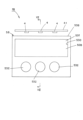
図1、図2、図3、図4および図8中、符号1は、この実施形態1にかかる車両用灯具である。車両用灯具1は、この例では、リアコンビネーションランプを構成するテール・ストップランプである。なお、車両用灯具1は、テール・ストップランプ以外に、ストップランプまたはテールランプであっても良い。車両用灯具1は、車両(図示せず)の後部の左右両側にそれぞれ取り付けられている。
(Description of Vehicle Lamp 1)
In Figures 1, 2, 3, 4 and 8,
車両用灯具1は、ランプハウジング2と、ランプレンズ3と、励起光源4と、発光ユニット5と、追加光源6と、を備える。
The
(ランプハウジング2の説明)
ランプハウジング2(図8中の二点鎖線を参照)は、たとえば、光不透過性の部材(樹脂部材など)から構成されている。
(Explanation of Lamp Housing 2)
The lamp housing 2 (see the two-dot chain line in FIG. 8) is made of, for example, a light-impermeable material (such as a resin material).
(ランプレンズ3の説明)
ランプレンズ3は、たとえば、素通しのアウターカバー、アウターレンズなどである。ランプレンズ3は、この例では、PMMA、PCなどの光透過性の樹脂部材から構成されている。
(Explanation of Lamp Lens 3)
The
ランプレンズ3は、ランプハウジング2に取り付けられている。これにより、ランプハウジング2とランプレンズ3とは、灯室23を形成する。
The
ランプレンズ3の内面(灯室23側に向く面)のうち、発光ユニット5が固定される個所には、凹部(座ぐり)30が設けられている。凹部30は、発光ユニット5がランプレンズ3の所定の位置に位置決めされて固定されるための手段である。
A recess (spot) 30 is provided on the inner surface of the lamp lens 3 (the surface facing the lamp chamber 23) where the light-emitting
ランプレンズ3の素材としては、可視光領域において透過率が高い素材が好ましい。ランプレンズ3は、この例では、赤色をなす。この結果、ランプレンズ3は、赤色光L1およびL2(図1および図2中の実線矢印を参照)を透過し、赤色光L1、L2以外の光を吸収する。すなわち、ランプレンズ3は、発光ユニット5において発生した赤色光L1としてのフォトルミネッセンスL1を透過させて灯室23外に照射させるレンズである。
The
(励起光源4の説明)
励起光源4は、この例では、LEDやLD(半導体レーザー)などを使用して、励起光L3(図1および図2中の破線矢印を参照)を照射するものである。励起光L3は、波長が短い光、たとえば、青色光、紫光、紫外光などである。
(Explanation of Excitation Light Source 4)
In this example, the
励起光源4は、図8に示すように、ランプハウジング2に取り付けられていて、灯室23内に配置されている。励起光源4の光軸40は、発光ユニット5の発光面(図3中の格子模様が施されている長方形、および、図4中の斜線模様が施されている長方形を参照)に対して、この例では、約45°傾斜している。光軸40は、励起光源4の発光面の中心を通り、かつ、励起光源4の発光面に対して垂直である。励起光源4は、この例では、テール・ストップランプ用の光源である。
As shown in FIG. 8, the
(発光ユニット5の説明)
発光ユニット5は、ランプレンズ3の灯室23側に固定されていて、励起光源4から照射された励起光L3によりフォトルミネッセンスL1を発生させる。発光ユニット5は、発光層50と、基板(支持基板)51とを有する。
(Explanation of Light Emitting Unit 5)
The light-emitting
発光層50は、有機発光材料(有機蛍光体材料)や無機発光材料(無機蛍光体材料)などからなる。発光層50は、励起光源4から照射された励起光L3によりフォトルミネッセンスL1を発生させる。フォトルミネッセンスL1は、この例では、波長が励起光L3よりも長い赤色光L1である。
The light-emitting
発光層50は、この例では、長方形の面形状をなす。この結果、車両用灯具1は、長方形の面形状の発光層50において発生したフォトルミネッセンスL1により、長方形の面発光(図3中の格子模様が施されている長方形、および、図4中の斜線模様が施されている長方形を参照)が得られる。
In this example, the light-emitting
基板51は、励起光源4から照射された励起光L3および追加光源6から照射された赤色光L2を透過させる。基板51は、この例では、PMMA、PCなどの光透過性の樹脂部材や光透過性のガラスなどから構成されている。基板51は、フレキシブル性またはリジッド性を問わない。
The
基板51は、この例では、発光層50よりも一回り大きい長方形の板形状をなす。基板51の長方形の一面には、長方形の面形状の発光層50が形成(成膜)されている。
In this example, the
発光ユニット5は、接着剤52により、ランプレンズ3の内面の凹部30に位置決めされて固定されている。
The light-emitting
この時、発光層50は、ランプレンズ3に接着剤52を介して向き合っている。この結果、発光層50は、接着剤52を介してランプレンズ3に封止された状態で固定されている。すなわち、発光層50とランプレンズ3との間には、屈折率が空気の屈折率1よりも大きい接着剤52が存在していて、屈折率が1の空気が存在しない。これにより、発光層50において発生したフォトルミネッセンスL1は、空気を介さずに接着剤52を介してランプレンズ3に入射することができる。
At this time, the light-emitting
基板51は、灯室23内において、励起光源4および追加光源6に向き合っている。基板51の一部分(発光層50が形成されている一板面側の部分)は、ランプレンズ3の凹部30に嵌合していて、かつ、接着剤52に密着している。基板51は、接着剤52と共に発光層50を封止する。
The
接着剤52は、発光層50において発生したフォトルミネッセンスL1および追加光源6から照射された赤色光L2を透過させる。接着剤52は、この例では、シリコーン樹脂やエポキシ樹脂などから構成されている。接着剤52の屈折率とランプレンズ3の屈折率とは、同様であることが好ましい。
The adhesive 52 transmits the photoluminescence L1 generated in the light-emitting
(追加光源6の説明)
追加光源6は、赤色光L2を照射する。追加光源6は、この例では、LEDやLD(半導体レーザー)などを使用する。追加光源6から照射される赤色光L2は、フォトルミネッセンスL1とほぼ同様な波長の赤色光である。
(Explanation of Additional Light Source 6)
The additional
追加光源6は、ランプハウジング2に取り付けられていて、灯室23内に配置されている。追加光源6の光軸60は、発光ユニット5の発光面に対して、この例では、約45°傾斜している。この結果、追加光源6の光軸60と励起光源4の光軸40とは、約90°で交差している。光軸60は、追加光源6の発光面の中心を通り、かつ、追加光源6の発光面に対して垂直である。追加光源6は、この例では、ストップランプ用の光源である。
The additional
(車両用灯具1の組付け工程の説明)
以下、車両用灯具1の組付け工程について図5から図8を参照して説明する。まず、ランプハウジング2を成形する。また、凹部30が設けられているランプレンズ3を成形する(図5を参照)。さらに、発光ユニット5を製造する。
(Description of the assembly process of the vehicle lamp 1)
The assembly process of the
つぎに、ランプレンズ3の凹部30中に接着剤52を塗布し、かつ、凹部30中に発光ユニット5を、発光層50をランプレンズ3側に向けて、嵌合させる(図6を参照)。ランプレンズ3と発光ユニット5とを接着剤52により接着して、ランプレンズ3と発光ユニット5との一体構造体を製造する(図7を参照)。
Next, adhesive 52 is applied to the
それから、ランプハウジング2とランプレンズ3とを取り付けて灯室23を形成する。その灯室23内に励起光源4および追加光源6を配置する。これにより、車両用灯具1が組付けられる(図8を参照)。
Then, the
(実施形態1の作用の説明)
この実施形態1にかかる車両用灯具1は、以上のごとき構成からなり、以下、その作用について説明する。
(Description of the Function of the First Embodiment)
The
まず、励起光源4を点灯する。すると、励起光源4の発光面から励起光L3がランバーシアン分布を形成するように発光ユニット5側に照射される。励起光L3は、発光ユニット5の基板51を透過して発光ユニット5の発光層50に照射される。
First, the
発光層50は、励起光L3により、フォトルミネッセンスL1を発生する。フォトルミネッセンスL1は、接着剤52およびランプレンズ3を透過して車両用灯具1の外部に所定のテールランプの配光パターンで照射される。この時、車両用灯具1は、図4中の斜線模様が施されている長方形の面発光が得られる。
The light-emitting
また、励起光源4が点灯している状態において、追加光源6を追加点灯する。すると、追加光源6の発光面から赤色光L2がランバーシアン分布を形成するように発光ユニット5側に追加照射される。
In addition, when the
赤色光L2は、発光ユニット5の基板51、発光層50、接着剤52およびランプレンズ3を透過して車両用灯具1の外部に所定のストップランプの配光パターンで照射される。同時に、前記のフォトルミネッセンスL1も、接着剤52およびランプレンズ3を透過して車両用灯具1の外部に所定のストップランプの配光パターンで照射される。この時、車両用灯具1は、図3中の格子模様が施されている長方形の面発光が得られる。
The red light L2 passes through the
(実施形態1の効果の説明)
この実施形態1にかかる車両用灯具1は、以上のごとき構成および作用からなり、以下、その効果について説明する。
(Explanation of Effects of First Embodiment)
The
この実施形態1にかかる車両用灯具1は、ランプレンズ3の灯室23側に発光ユニット5を固定したものであるから、励起光源4から照射された励起光L3により発生したフォトルミネッセンスL1が空気(空気層)を介さずに直接ランプレンズ3に入射する。すなわち、発光ユニット5からのフォトルミネッセンスL1は、空気(空気層)からランプレンズ3に入射する時に、ランプレンズ3の入射面において全反射することがない。
In the
この結果、この実施形態1にかかる車両用灯具1は、発光ユニット5からのフォトルミネッセンスL1をほとんど全部、ランプレンズ3に入射させることができるので、フォトルミネッセンスL1を有効に利用することができる。
As a result, the
この実施形態1にかかる車両用灯具1は、発光ユニット5が発光層50と基板51都から構成されていて、発光層50がランプレンズ3に接着剤52を介して向き合って密封された状態で固定されているものである。この結果、この実施形態1にかかる車両用灯具1は、フォトルミネッセンスL1がほとんど全部、接着剤52を介してランプレンズ3に入射することができ、これにより、フォトルミネッセンスL1を有効に利用することができる。
In the
しかも、この実施形態1にかかる車両用灯具1は、基板51が励起光L3を透過させる部材からなり、また、接着剤52がフォトルミネッセンスL1を透過させる部材からなるものであるから、励起光L3およびフォトルミネッセンスL1を有効に利用することができる。
Moreover, in the
この実施形態1にかかる車両用灯具1は、ランプレンズ3の凹部30中に発光ユニット5の発光層50の全部および基板51の一部分を収納させることができるので、発光層50において発生したフォトルミネッセンスL1の全部をランプレンズ3に入射させることができ、フォトルミネッセンスL1を有効に利用することができる。
The
この実施形態1にかかる車両用灯具1は、ランプレンズ3の凹部30中に発光ユニット5を位置決めして固定することができる。この結果、この実施形態1にかかる車両用灯具1は、発光ユニット5の位置精度が向上されるので、フォトルミネッセンスL1を高精度に制御することができ、フォトルミネッセンスL1の照射により形成される配光パターン(テールランプの配光パターンおよびストップランプの配光パターン)を高精度に制御することができる。
The
この実施形態1にかかる車両用灯具1は、フォトルミネッセンスL1が赤色光であり、ランプレンズ3が赤色光を透過し赤色光以外の光を吸収するレンズである。この結果、この実施形態1にかかる車両用灯具1は、赤色光のフォトルミネッセンスL1を有効に利用することができる。
In the
この実施形態1にかかる車両用灯具1は、灯室23内に、赤色光L2を照射する追加光源6を、配置するものであるから、赤色光のフォトルミネッセンスL1と赤色光L2とを共に有効に利用することができる。しかも、この実施形態1にかかる車両用灯具1は、赤色光のフォトルミネッセンスL1と赤色光L2とにより、2つのランプ機能、たとえば、テールランプ機能とストップランプ機能とを有する。
The
(実施形態2の構成、作用、効果の説明)
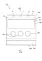
図9および図10は、この発明にかかる車両用灯具の実施形態2を示す。以下、この実施形態2にかかる車両用灯具1Aの構成、作用、効果について説明する。図中、図1~図8と同符号は、同一物を示す。
(Description of the configuration, operation, and effects of the second embodiment)
9 and 10 show a second embodiment of a vehicle lamp according to the present invention. The configuration, operation, and effects of a vehicle lamp 1A according to the second embodiment will be described below. In the drawings, the same reference numerals as those in FIGS. 1 to 8 denote the same parts.
この実施形態2にかかる車両用灯具1Aは、前記の実施形態1にかかる車両用灯具1の変形例である。なお、この実施形態2にかかる車両用灯具1Aのランプハウジング(図示せず)、ランプレンズ3、励起光源(図示せず)、発光層50、基板51、接着剤52および追加光源(図示せず)などの部品は、前記の実施形態1にかかる車両用灯具1のランプハウジング2、ランプレンズ3、励起光源4、発光層50、基板51、接着剤52および追加光源6などの部品と同様の構成からなる。
The vehicle lamp 1A according to this
前記の実施形態1にかかる車両用灯具1の発光ユニット5が、発光層50と、基板51と、からなるものである。これに対して、この実施形態2にかかる車両用灯具1Aの発光ユニット5Aが、発光層50と、基板51と、封止部材53、54と、からなるものである。封止部材53、54は、封止基板53と、封止基板53を発光層50に封止接着させる封止接着剤54と、を有するものである。
The light-emitting
封止基板53は、フォトルミネッセンスL1および赤色光L2を透過させる。封止基板53は、基板51と同様に、この例では、PMMA、PCなどの光透過性の樹脂部材や光透過性のガラスなどから構成されている。封止基板53は、フレキシブル性またはリジッド性を問わない。封止基板53は、基板51とほぼ同じ大きさおよび形状をなす。封止基板53の屈折率とランプレンズ3の屈折率とは、同様であることが好ましい。
The sealing
封止接着剤54は、フォトルミネッセンスL1および赤色光L2を透過させる。封止接着剤54は、接着剤52と同様に、この例では、シリコーン樹脂やエポキシ樹脂などから構成されている。封止接着剤54の屈折率と封止基板53の屈折率およびランプレンズ3の屈折率とは、同様であることが好ましい。
The sealing
(発光ユニット5Aの製造工程の説明)
以下、発光ユニット5Aの製造工程について図9を参照して説明する。まず、基板51を製造する(図9(A)参照)。つぎに、基板51に発光層50を形成(成膜)する(図9(B)参照)。これにより、前記の実施形態1にかかる車両用灯具1の発光ユニット5が製造される。
(Description of Manufacturing Process of Light-Emitting
Hereinafter, the manufacturing process of the light-emitting
基板51の製造と別個に、封止基板53を製造する。それから、発光層50および基板51と封止基板53とを封止接着剤54により接着する(図9(C)参照)。すると、発光層50は、封止部材(封止基板53および封止接着剤54)により、封止される(図9(D)参照)。
The sealing
これにより、この実施形態2にかかる車両用灯具1Aの発光ユニット5Aが製造される。この時、発光層50は、封止接着剤54を介して封止基板53に向き合っている。また、基板51の一部分(発光層50の4辺の周囲の部分)は、封止接着剤54に接着されている。
This produces the light-emitting
前記の製造工程により製造された発光ユニット5Aは、ランプレンズ3の灯室23側に接着剤52を介して固定される。たとえば、図10(A)に示すように、発光ユニット5Aは、ランプレンズ3の凹部30中に接着剤52を介して固定される。または、図10(A)に示すように、発光ユニット5Aは、ランプレンズ3の灯室23側の面に接着剤52を介して固定される。この時、封止部材(封止基板53および封止接着剤54)は、ランプレンズ3に向かい合っている。
The light-emitting
この実施形態2にかかる車両用灯具1Aは、以上のごとき構成からなるものであるから、前記の実施形態1にかかる車両用灯具1と同様の作用、効果を達成することができる。特に、この実施形態2にかかる車両用灯具1Aは、発光層50を封止部材(封止基板53および封止接着剤54)により封止して保護することができる。
The vehicle lamp 1A according to the second embodiment is configured as described above, and therefore can achieve the same effects and advantages as the
(実施形態3の構成の説明)
図11から図13は、この発明にかかる車両用灯具の実施形態3を示す。以下、この実施形態3にかかる車両用灯具1Bの構成について説明する。図中、図1~図10と同符号は、同一物を示す。
(Description of the configuration of the third embodiment)
11 to 13 show a third embodiment of a vehicle lamp according to the present invention. The configuration of a
(車両用灯具1Bの説明)
この実施形態3にかかる車両用灯具1Bは、前記の実施形態1、2にかかる車両用灯具1、1Aと、ほぼ同様に、ランプハウジング(図示せず)と、ランプレンズ3と、励起光源4と、発光ユニット5Bと、を備える。
(Description of
The
前記の実施形態1、2にかかる車両用灯具1、1Aは、ランプレンズ3に発光ユニット5、5Aを固定したものである。これに対して、この実施形態3にかかる車両用灯具1Bは、発光ユニット5Bをランプレンズ3に固定しないで灯室23内に配置したものである。
In the
(励起光源4の説明)
励起光源4は、この例では、取付部材41の下面に、等間隔に間を開けて3個取り付けられている。励起光源4の発光面は、下方に向いている。なお、励起光源4の個数は、特に限定しない。
(Explanation of Excitation Light Source 4)
In this example, three
(発光ユニット5Bの説明)
発光ユニット5Bは、励起光源4の下方に配置されている。発光ユニット5Bは、発光層50Bと、基板51Bと、封止基板53Bと、封止接着剤54Bと、第1出射部531と、第2出射部532と、を有する。
(Explanation of
The light-emitting
この実施形態3の発光ユニット5Bの構成部品、すなわち、発光層50B、基板51B、封止基板53Bおよび封止接着剤54Bの材料は、前記の実施形態1、2の発光ユニット5、5Aの構成部品、すなわち、発光層50、基板51、封止基板53および封止接着剤54の材料と同じ材料を使用する。
The materials of the components of the light-emitting
基板51B、封止基板53Bおよび封止接着剤54Bは、発光層50BからのフォトルミネッセンスL1および励起光源4からの励起光L3を透過させる。また、基板51Bおよび封止基板53Bは、フォトルミネッセンスL1を全反射作用により導く導光機能を有する。
The
発光層50Bは、この例では、左右に長い長方形の面形状をなす。基板51Bおよび封止基板53Bは、この例では、発光層50Bよりも一回り大きく、かつ、上下が発光層50Bの上下よりも倍以上大きい長方形の板形状をなす。
In this example, the light-emitting
基板51Bの一面の上部分には、発光層50Bが形成(成膜)されている。封止基板53Bの一面(発光層50Bおよび基板51Bに向き合う面)の上部分には、凹部530が発光層50Bに対応して設けられている。
A light-emitting
封止基板53Bの他面の上部分には、第1出射部531が設けられている。第1出射部531と凹部530とは、封止基板53Bの両面において相互に対応して設けられている。この結果、第1出射部531は、発光層50Bと同様に、左右に長い長方形の面形状をなす。第1出射部531は、封止基板53B(基板)中を透過したフォトルミネッセンスL1を封止基板53B(基板)の外に出射させる。
A
封止基板53Bの他面の下部分には、第2出射部532が複数個、この例では、3個設けられている。第2出射部532は、円形形状をなしていて、封止基板53Bの他面から突出している。第2出射部532は、封止基板53B(基板)中を全反射するフォトルミネッセンスL1を封止基板53B(基板)の外に出射させる。
A plurality of
(発光ユニット5Bの製造工程の説明)
以下、発光ユニット5Bの製造工程について図13を参照して説明する。まず、基板51Bを製造する(図13(A)参照)。つぎに、基板51Bの一面の上部分に発光層50Bを形成(成膜)する(図13(B)参照)。
(Description of Manufacturing Process of Light-Emitting
A manufacturing process of the light-emitting
基板51Bの製造と別個に、封止基板53Bを製造する。それから、発光層50Bの一面および基板51Bの一面と封止基板53Bの一面とを封止接着剤54により接着する(図13(C)参照)。すると、発光層50Bは、基板51B、封止基板53Bおよび封止接着剤54Bにより封止される(図13(D)参照)。
The sealing
これにより、この実施形態3にかかる車両用灯具1Bの発光ユニット5Bが製造される。この時、発光層50Bは、封止接着剤54Bを介して封止基板53Bに向き合っている。また、基板51Bの発光層50B以外の部分は、封止接着剤54Bを介して封止基板53Bに接着されている。
This produces the light-emitting
前記の製造工程により製造された発光ユニット5Bは、車両用灯具1Bの灯室23内のうち、励起光源4の下方に配置される。発光ユニット5Bの上側端面は、励起光源4の発光面に向き合わせとなる。発光ユニット5Bの第1出射部531および第2出射部532は、ランプレンズ3に向き合わせとなる。なお、励起光源4を発光ユニット5Bの左側端面、右側端面の少なくともいずれか一方に配置しても良い。また、励起光源4を発光ユニット5Bに対して、ランプレンズ3側に、あるいは、ランプレンズ3に対して反対側に、傾斜させて配置しても良い。
The light-emitting
(実施形態3の作用の説明)
この実施形態3にかかる車両用灯具1Bは、以上のごとき構成からなり、以下、その作用について説明する。
(Description of the Function of the Third Embodiment)
The
まず、励起光源4を点灯する。すると、励起光源4の発光面から励起光L3がランバーシアン分布を形成するように発光ユニット5B側に照射される。励起光L3は、発光ユニット5の上端面から基板51B、封止基板53Bおよび封止接着剤54B中に入射して、かつ、基板51B、封止基板53Bおよび封止接着剤54B中を透過して発光層50Bに照射される。
First, the
発光層50Bは、励起光L3により、フォトルミネッセンスL1を発生する。フォトルミネッセンスL1の一部分は、封止接着剤54Bおよび封止基板53Bを透過して第1出射部531から封止基板53Bの外に出射する。
The light-emitting
また、フォトルミネッセンスL1の残りの大部分は、基板51Bの他面と封止基板53Bの他面において全反射しながら、基板51B、封止基板53Bおよび封止接着剤54B中を透過して第2出射部532から封止基板53Bの外に出射する。
Moreover, most of the remaining photoluminescence L1 is totally reflected at the other surface of the
第1出射部531および第2出射部532から封止基板53Bの外に出射したフォトルミネッセンスL1は、ランプレンズ3を透過して車両用灯具1Bの外部に所定のテールランプの配光パターンまたは所定のストップランプの配光パターンで照射される。
The photoluminescence L1 emitted from the
この時、車両用灯具1Bは、第1出射部531における左右に長い長方形の面発光(図11を参照)と、第2出射部532における3個の円形の面発光(図11を参照)とが得られる。
At this time, the
(実施形態3の効果の説明)
この実施形態3にかかる車両用灯具1Bは、以上のごとき構成および作用からなり、以下、その効果について説明する。
(Explanation of Effects of the Third Embodiment)
The
この実施形態3にかかる車両用灯具1Bは、封止基板53B(基板)に第1出射部531および第2出射部532を設けたものである。この結果、この実施形態3にかかる車両用灯具1Bは、発光層50Bから直接封止接着剤54Bおよび封止基板53B(基板)中を透過したフォトルミネッセンスL1の一部分を第1出射部531から封止基板53B(基板)の外に出射させることができる。また、この実施形態3にかかる車両用灯具1Bは、フォトルミネッセンスL1の残りの大部分であって第1出射部531から封止基板53B(基板)の外に出射しなかったフォトルミネッセンスL1を、基板51Bの他面と封止基板53Bの他面において全反射させながら、基板51B、封止基板53Bおよび封止接着剤54B中を透過させて第2出射部532から封止基板53B(基板)の外に出射させることができる。これにより、この実施形態3にかかる車両用灯具1Bは、フォトルミネッセンスL1をさらに有効に利用することができる。
The
この実施形態3にかかる車両用灯具1Bは、前記の実施形態1、2にかかる車両用灯具1、1Aと同様に、フォトルミネッセンスL1が赤色光であり、ランプレンズ3が赤色光を透過し赤色光以外の光を吸収するレンズ(赤色レンズ)である。この結果、この実施形態3にかかる車両用灯具1Bは、赤色光のフォトルミネッセンスL1を有効に利用することができる。
In the
(実施形態4の構成、作用、効果の説明)
図14および図15は、この発明にかかる車両用灯具の実施形態4を示す。以下、この実施形態4にかかる車両用灯具1Cの構成、作用、効果について説明する。図中、図1~図13と同符号は、同一物を示す。
(Description of the configuration, operation, and effects of the fourth embodiment)
14 and 15 show a fourth embodiment of a vehicle lamp according to the present invention. The configuration, operation, and effects of a
この実施形態4にかかる車両用灯具1Cは、前記の実施形態3にかかる車両用灯具1Bの変形例である。なお、この実施形態4にかかる車両用灯具1Cのランプハウジング(図示せず)、励起光源4および発光ユニット5C(発光層50C、基板51Cおよび封止基板53C)などの部品は、前記の実施形態3にかかる車両用灯具1Bのランプハウジング、励起光源4および発光ユニット5B(発光層50B、基板51Bおよび封止基板53B)などの部品と同様の構成からなる。
The
前記の実施形態3にかかる車両用灯具1Bは、ランプレンズ3として、赤色光を透過し赤色光以外の光を吸収するレンズ(赤色レンズ)を使用するものである。これに対して、この実施形態4にかかる車両用灯具1Cは、ランプレンズ3Cとして、無色透明なレンズを使用するものである。
The
この実施形態4にかかる車両用灯具1Cは、ランプレンズ3Cと発光ユニット5Cの第1出射部531との間に、遮光部材55Cを配置する。遮光部材55Cは、赤色光であるフォトルミネッセンスL1を始めとする光を遮断する。
In the
この実施形態4にかかる車両用灯具1Cは、以上のごとき構成からなるものであるから、前記の実施形態3にかかる車両用灯具1Bと同様の作用、効果を達成することができる。
The
特に、この実施形態4にかかる車両用灯具1Cは、ランプレンズ3Cとして無色透明なレンズを使用するものであるから、非点灯時において、車両用灯具1Cの外部からランプレンズ3Cおよび発光ユニット5Cの第2出射部532の部分を通して、灯室23内を透けて見える。また、点灯時においては、発光ユニット5Cの第2出射部532の3個の円形の面発光が見える。このように、この実施形態4にかかる車両用灯具1Cは、非点灯時において、透明に近いデザインが得られ、また、点灯時において、任意のデザインの形状の発光面が得られる。
In particular, the
(実施形態5の構成、作用、効果の説明)
図16および図17は、この発明にかかる車両用灯具の実施形態5を示す。以下、この実施形態5にかかる車両用灯具1Dの構成、作用、効果について説明する。図中、図1~図15と同符号は、同一物を示す。
(Description of the configuration, operation, and effects of the fifth embodiment)
16 and 17 show a vehicle lamp according to a fifth embodiment of the present invention. The configuration, operation, and effects of a
この実施形態5にかかる車両用灯具1Dは、前記の実施形態3にかかる車両用灯具1Bの変形例である。なお、この実施形態5にかかる車両用灯具1Dのランプハウジング(図示せず)、ランプレンズ3、励起光源4および発光ユニット5D(発光層50D、基板51Dおよび封止基板53D)などの部品は、前記の実施形態3にかかる車両用灯具1Bのランプハウジング、ランプレンズ3、励起光源4および発光ユニット5B(発光層50B、基板51Bおよび封止基板53B)などの部品と同様の構成からなる。
The
この実施形態5にかかる車両用灯具1Dは、リフレクタ56Dを備える。リフレクタ56Dは、発光ユニット5Dの基板(すなわち、基板51Dおよび封止基板53D)の第2出射部532側の部分の端面(下側端面)に向き合って配置されている。
The
この実施形態5にかかる車両用灯具1Dにおいて、前記の実施形態3、4にかかる車両用灯具1B、1Cと、同様に、励起光源4の発光面は、発光ユニット5Dの基板(すなわち、基板51Dおよび封止基板53D)の第1出射部531側の部分の端面(上側端面)に向き合っている。
In the
この実施形態5にかかる車両用灯具1Dにおいて、励起光源4とリフレクタ56Dとは、発光ユニット5Dを挟んで上下に配置されている。
In the
リフレクタ56Dの内面には、反射面560が設けられている。反射面560は、発光ユニット5Dの基板の第2出射部532側の端面と、ランプレンズ3の内面(灯室23側の面)とに、それぞれ、向き合っている。この結果、反射面560は、発光ユニット5Dの基板中を全反射して基板の第2出射部532側の端面から外に出たフォトルミネッセンスL1をランプレンズ3側に反射させる。
A
この実施形態5にかかる車両用灯具1Dは、以上のごとき構成からなるものであるから、前記の実施形態3、4にかかる車両用灯具1B、1Cと同様の作用、効果を達成することができる。
The
特に、この実施形態5にかかる車両用灯具1Dは、反射面560を有するリフレクタ56Dを備えるものである。この結果、この実施形態5にかかる車両用灯具1Dは、リフレクタ56Dの反射面560により、発光ユニット5Dの基板中を全反射して基板の第2出射部532側の端面から外に出たフォトルミネッセンスL1をランプレンズ3側に反射させることができる。これにより、この実施形態5にかかる車両用灯具1Dは、フォトルミネッセンスL1をさらに有効に利用することができる。
In particular, the
すなわち、この実施形態5にかかる車両用灯具1Dは、発光層50Bから直接基板中を透過したフォトルミネッセンスL1を第1出射部531から基板の外に出射させ、また、第1出射部531から基板の外に出射しなかったフォトルミネッセンスL1を、基板中において全反射させながら基板中を透過させて第2出射部532から基板の外に出射させ、さらに、第2出射部532から基板の外に出射しなかったフォトルミネッセンスL1を、基板中において全反射させながら基板中を透過させて基板の下側端面から基板の外に出射させるものである。このように、この実施形態5にかかる車両用灯具1Dは、フォトルミネッセンスL1をさらに有効に利用することができる。
In other words, the
(実施形態6の構成、作用、効果の説明)
図18および図19は、この発明にかかる車両用灯具の実施形態6を示す。以下、この実施形態6にかかる車両用灯具1Eの構成、作用、効果について説明する。図中、図1~図17と同符号は、同一物を示す。
(Description of the configuration, operation, and effect of the sixth embodiment)
18 and 19 show a vehicle lamp according to a sixth embodiment of the present invention. The configuration, operation, and effects of a
この実施形態6にかかる車両用灯具1Eは、前記の実施形態3にかかる車両用灯具1Bの変形例である。なお、この実施形態6にかかる車両用灯具1Eのランプハウジング(図示せず)、ランプレンズ3、励起光源4および発光ユニット5E(発光層50E、基板51Eおよび封止基板53E)などの部品は、前記の実施形態3にかかる車両用灯具1Bのランプハウジング、ランプレンズ3、励起光源4および発光ユニット5B(発光層50B、基板51Bおよび封止基板53B)などの部品と同様の構成からなる。
The
この実施形態6にかかる車両用灯具1Eは、前記の実施形態3にかかる車両用灯具1Bにおいて、3個の第2出射部532を結ぶ直線に対して上下対称となっている。すなわち、励起光源4が、発光ユニット5Eの上下にそれぞれ配置されている。発光ユニット5Eにおいて、発光層50Eおよび第1出射部531が、3個の第2出射部532を結ぶ直線に対して上下対称にそれぞれ配置されている。
The
この実施形態6にかかる車両用灯具1Eは、以上のごとき構成からなるものであるから、前記の実施形態3にかかる車両用灯具1Bと同様の作用、効果を達成することができる。
The
特に、この実施形態6にかかる車両用灯具1Eは、励起光源4、発光層50Eおよび第1出射部531を、3個の第2出射部532を結ぶ直線に対して上下対称にそれぞれ配置させたものである。この結果、この実施形態6にかかる車両用灯具1Eは、広い面積の発光面が得られる。
In particular, in the
(実施形態7の構成の説明)
図20は、この発明にかかる車両用灯具の実施形態7を示す。以下、この実施形態7にかかる車両用灯具1Fの構成について説明する。図中、図1~図19と同符号は、同一物を示す。
(Description of the configuration of the seventh embodiment)
20 shows a seventh embodiment of a vehicle lamp according to the present invention. The configuration of a
(車両用灯具1Fの説明)
この実施形態7にかかる車両用灯具1Fは、前記の実施形態1、3にかかる車両用灯具1、1Bと、ほぼ同様に、ランプハウジング(図示せず)と、ランプレンズ(図示せず)と、励起光源4と、発光ユニット5Fと、を備える。
(Description of
The
前記の実施形態1、3にかかる車両用灯具1、1Bは、励起光源4の発光面からランバーシアン分布を形成するように照射された励起光L3を、発光ユニット5、5Bにそのまま入射させて、かつ、発光層50、50Bにそのまま照射させるものである。これに対して、この実施形態7にかかる車両用灯具1Fは、励起光源4からの励起光L3を、発光ユニット5Fに制御させて入射させて、かつ、発光層50Fに制御させて照射させるものである。
In the
(発光ユニット5Fの説明)
発光ユニット5Fは、発光層50Fと、基板51Fと、を有する。なお、この実施形態7の発光ユニット5Fは、前記の実施形態2、3の発光ユニット5A、5Bと同様に、発光層50Fを、封止基板(図示せず)および封止接着剤(図示せず)により、封止しても良い。
(Explanation of
The light-emitting
この実施形態7の発光ユニット5Fの構成部品、すなわち、発光層50Fおよび基板51Fの材料は、前記の実施形態1、3の発光ユニット5、5Bの構成部品、すなわち、発光層50、50Bおよび基板51、51Bの材料と同じ材料を使用する。
The components of the light-emitting
発光層50Fは、灯室(図示せず)ないにおいて、ランプレンズに向き合って配置されている。
The light-emitting
基板51Fは、第1入射面571、第2入射面572、第1反射面573、第2反射面574および出射面570を有する。
The
第1入射面571は、励起光源4からの励起光L3(励起光源4の発光面の中心を点(角の頂点)とする立体角が約70°~80°の励起光L3)を、平行な第1入射光として屈折入射させる面である。第1入射光は、励起光源4の光軸(以下、「光軸」と称する)と平行である。第1入射面571は、励起光源4の発光面に対向して設けられている。第1入射面571は、発光面の中心を焦点とする双曲線を、双曲線の主軸(光軸)を回転軸として回転させてなる回転双曲面の屈折面である。
The
第2入射面572は、励起光源4からの励起光L3(励起光源4の発光面の中心を点(角の頂点)とする立体角が約70°~80°から約180°までの間の励起光L3)を、第2入射光として屈折入射させる面である。第2入射面572は、第1入射面571の外周側部であって、励起光源4の発光面に対向して設けられている。第2入射面572は、直線もしくは曲線を、光軸を回転軸として回転させてなる回転面の屈折面である。
The
第1反射面573は、第2入射面572から入射した第2入射光(入射光の一部)を光軸と平行な第1反射光として全反射させる面である。第1反射面573は、励起光源4の発光面の中心を焦点とする放物線を、光軸を回転軸として回転させてなる回転放物面の反射面である。または、第1反射面573は、前記の放物線に倣った直線を、光軸を回転軸として回転させてなる回転面の反射面である。
The first reflecting
第2反射面574は、第1入射面571から入射した光軸と平行な第1入射光(入射光の一部)と、第2入射面572から入射した第2入射光(入射光の一部)であって、第1反射面573で全反射された光軸と平行な第1反射光とを、光軸に対して垂直であり、かつ、相互に平行な第2反射光として全反射させる面である。第2反射面574は、複数段、この例では、5段の平面の反射面である。
The second reflecting
出射面570は、第2反射面547から反射した第2反射光を、光軸に対して垂直であり、かつ、相互に平行な出射光として出射させる平面である。出射面570には、発光層50Fが形成(成膜)されている。この結果、出射面570から出射する出射光(励起光源4からの励起光L3)は、発光層50Fを照射する。これにより、発光層50Fは、フォトルミネッセンスL1を照射する。
The
基板51Fの出射面570に対して反対側の部分には、取付部575が一体に設けられている。取付部575には、取付孔576が設けられている。取付部575は、取付孔576を通したスクリューなど(図示せず)により、ランプハウジングに直接またはブラケットなどを介して間接に取り付けられる。この結果、発光ユニット5Fは、基板51Fの取付部575により、ランプハウジングに直接または間接に取り付けられる。
A mounting
(実施形態7の作用の説明)
この実施形態7にかかる車両用灯具1Fは、以上のごとき構成からなり、以下、その作用について説明する。
(Explanation of the operation of the seventh embodiment)
The
まず、励起光源4を点灯する。すると、励起光源4の発光面から励起光L3がランバーシアン分布を形成するように発光ユニット5Fの第1入射面571および第2入射面572側に照射される。
First, the
励起光L3の一部分は、第1入射面571から光軸に平行な第1入射光として基板51F中に入射する。また、励起光L3の残りの部分は、第2入射面572から第2入射光として基板51F中に入射し、かつ、第1反射面573で光軸に平行な第1反射光として反射する。
A portion of the excitation light L3 enters the
光軸に平行な第1入射光と第1反射光とは、第2反射面574で光軸に対して垂直であり、かつ、相互に平行な第2反射光として全反射する。この第2反射光は、出射面570から出射光として出射して発光層50Fを照射する。これにより、発光層50Fは、フォトルミネッセンスL1をランプレンズ側に照射する。フォトルミネッセンスL1は、ランプレンズを透過して、車両用灯具1Fの外部に所定の配光パターンで照射される。
The first incident light and the first reflected light, which are parallel to the optical axis, are totally reflected by the second reflecting
(実施形態7の効果の説明)
この実施形態7にかかる車両用灯具1Fは、以上のごとき構成および作用からなり、以下、その効果について説明する。
(Explanation of Effects of the Seventh Embodiment)
The
この実施形態7にかかる車両用灯具1Fは、発光ユニット5Fの基板51Fに、第1入射面571、第2入射面572、第1反射面573、第2反射面574および出射面570を、設けたものである。この結果、この実施形態7にかかる車両用灯具1Fは、励起光源4からの励起光L3を、発光ユニット5Fに平行光(平行な励起光L3)として制御させて入射させて、かつ、発光層50Fに平行光(平行な励起光L3)として制御させて照射さることができる。これにより、この実施形態7にかかる車両用灯具1Fは、発光層50FからフォトルミネッセンスL1を制御させて出射させることができ、しかも、フォトルミネッセンスL1を有効に利用することができる。
The
この実施形態7にかかる車両用灯具1Fは、基板51Fに取付部575を設けたものであるから、基板51Fの取付部575をランプハウジングに直接または間接に取り付けることにより、発光ユニット5Fをランプハウジングに直接または間接に取り付けることができる。この結果、この実施形態7にかかる車両用灯具1Fは、ランプレンズと励起光源4と発光ユニット5Fとの相対位置関係を高精度に保つことができるので、励起光源4からの励起光L3を発光ユニット5Fに確実に入射させることができ、かつ、発光ユニット5FからのフォトルミネッセンスL1をランプレンズ側に確実に出射させることができる。これにより、この実施形態7にかかる車両用灯具1Fは、発光ユニット5FからのフォトルミネッセンスL1を確実に制御することができ、しかも、フォトルミネッセンスL1をさらに有効に利用することができる。
The
この実施形態7にかかる車両用灯具1Fにおいて、図20に示すように、発光層50Fの厚さを、実線に示すように薄くれれば、フォトルミネッセンスL1の赤色が薄くなり、二点鎖線に示すように厚くすれば、フォトルミネッセンスL1の赤色が濃くなる。このことは、前記の実施形態1~6にかかる車両用灯具1~1Eにおいても同様に、フォトルミネッセンスL1の赤色の濃淡を調整することができる。
In the
この実施形態7にかかる車両用灯具1Fは、前記の実施形態1、2、3、5、6にかかる車両用灯具1、1A、1B、1D、1Eと同様に、フォトルミネッセンスL1が赤色光であり、ランプレンズ3が赤色光を透過し赤色光以外の光を吸収するレンズ(赤色レンズ)である。この結果、この実施形態3にかかる車両用灯具1Bは、赤色光のフォトルミネッセンスL1を有効に利用することができる。
In the
(実施形態8の構成の説明)
図21および図22は、この発明にかかる車両用灯具の実施形態8を示す。以下、この実施形態8にかかる車両用灯具1Gの構成について説明する。図中、図1~図20と同符号は、同一物を示す。
(Description of the configuration of the eighth embodiment)
21 and 22 show an
(車両用灯具1Gの説明)
この実施形態8にかかる車両用灯具1Gは、前記の実施形態1~7にかかる車両用灯具1~1Fと、ほぼ同様に、ランプハウジング(図示せず)と、ランプレンズ3Gと、励起光源4と、を備える。
(Description of
The
前記の実施形態1~7にかかる車両用灯具1~1Fは、ランプレンズ3、3Cと別個に発光ユニット5~5Fを備えるものである。これに対して、この実施形態8にかかる車両用灯具1Gは、発光ユニットをランプレンズ3Gに兼用させるものである。この結果、この実施形態8にかかる車両用灯具1Gは、発光ユニットを備えない。
The
(ランプレンズ3Gの説明)
ランプレンズ3Gは、ランプハウジングと共に、灯室23を形成する。灯室23内には、励起光源4を配置させる。
(Explanation of
The
ランプレンズ3Gは、レンズ材料58と、蛍光体材料580と、を有する。レンズ材料58は、赤色着色剤が含まれた樹脂材料、たとえば、PMMAなどの通常の赤レンズである。蛍光体材料580は、赤色無機蛍光体材料、たとえば、CASNなどである。ランプレンズ3Gは、レンズ材料58と蛍光体材料580とを、射出成形(射出成型)時に、混ぜて、成形(成型)される。
蛍光体材料580は、粒子形状をなし、レンズ材料58中に含有されていて、励起光源4から照射された励起光L3によりフォトルミネッセンスL1を発生させる。
The
ランプレンズ3Gの透過率は、1%以上100%未満である。また、ランプレンズ3G中の蛍光体材料580の重量比は、0%越え50%以下である。さらに、ランプレンズ3Gの厚さは、0mm越え5mm以下である。なお、ランプレンズ3Gの透過率、ランプレンズ3G中の蛍光体材料580の重量比、および、ランプレンズ3Gの厚さは、この例の数値に限定されない。
The transmittance of the
(実施形態8の作用の説明)
この実施形態8にかかる車両用灯具1Gは、以上のごとき構成からなり、以下、その作用について説明する。
(Explanation of the Operation of the Eighth Embodiment)
The
励起光源4を点灯する。すると、励起光源4の発光面から励起光L3がランプレンズ3G側に照射される。励起光L3は、ランプレンズ3Gの内面(灯室23側の面)からランプレンズ3G中に入射する。ランプレンズ3G中に入射した励起光L3は、レンズ材料58中に含まれる蛍光体材料580を照射する。
The
蛍光体材料580は、励起光L3により、フォトルミネッセンスL1を発生する。フォトルミネッセンスL1は、レンズ材料58中を透過してランプレンズ3Gの外面(灯室23に対して反対側の面)から車両用灯具1Gの外部に所定の配光パターンで照射される。これにより、ランプレンズ3Gの外面が全面に亘って赤色に発光する。
The
(実施形態8の効果の説明)
この実施形態8にかかる車両用灯具1Gは、以上のごとき構成および作用からなり、以下、その効果について説明する。
(Explanation of Effects of the Eighth Embodiment)
The
この実施形態8にかかる車両用灯具1Gは、ランプレンズ3Gがレンズ材料58と蛍光体材料580とを有するものであるから、ランプレンズ3Gに励起光源4からの励起光L3を照射させることにより、ランプレンズ3G全体がフォトルミネッセンスL1により発光する。この結果、この実施形態8にかかる車両用灯具1Gは、フォトルミネッセンスL1を効率良く利用することができる。
In the
しかも、この実施形態8にかかる車両用灯具1Gは、ランプレンズ3Gをそなえることにより、発光ユニット5~5Fを備えなくとも、フォトルミネッセンスL1を照射することができる。この結果、この実施形態8にかかる車両用灯具1Gは、部品点数を軽減することができ、製造コストを安価にすることができる。
In addition, the
この実施形態8にかかる車両用灯具1Gは、ランプレンズ3Gの蛍光体材料580が無機蛍光体材料であるから、蛍光体材料580がランプレンズ3Gの射出成形時の温度に十分に耐えられる。
In the
この実施形態8にかかる車両用灯具1Gは、ランプレンズ3Gのレンズ材料58が赤色着色剤が含まれた樹脂材料、たとえば、PMMAなどの通常の赤レンズであり、また、ランプレンズ3Gの蛍光体材料580が赤色無機蛍光体材料、たとえば、CASNなどである。この結果、この実施形態8にかかる車両用灯具1Gは、赤色光のフォトルミネッセンスL1を有効に利用することができる。
In the
この実施形態8にかかる車両用灯具1Gは、ランプレンズ3Gの透過率が1%以上100%未満であるから、ランプレンズ3Gの透過率を任意に調整することができ、ランプレンズ3Gのデザインの自由度が増大する。
In the
この実施形態8にかかる車両用灯具1Gは、ランプレンズ3G中の蛍光体材料580の重量比が0%越え50%以下であるから、蛍光体材料580の重量比を任意に調整することができ、フォトルミネッセンスL1の発生量を調整することができ、フォトルミネッセンスL1のデザインの自由度が増大する。
In the
この実施形態8にかかる車両用灯具1Gは、ランプレンズ3Gの厚さが0mm越え5mm以下であるから、ランプレンズ3Gの厚さを任意に調整することができ、ランプレンズ3G中における励起光L3の吸収を調整することができ、励起光L3がランプレンズ3Gから車両用灯具1Gの外部に照射することを抑制できる。
In the
(実施形態9の構成、作用、効果の説明)
図23は、この発明にかかる車両用灯具の実施形態9を示す。以下、この実施形態9にかかる車両用灯具1Hの構成、作用、効果について説明する。図中、図1~図22と同符号は、同一物を示す。
(Description of the configuration, operation, and effect of the 9th embodiment)
23 shows a vehicular lamp according to a ninth embodiment of the present invention. The configuration, operation, and effects of a vehicular lamp 1H according to the ninth embodiment will be described below. In the figure, the same reference numerals as those in FIGS. 1 to 22 denote the same parts.
この実施形態9にかかる車両用灯具1Hは、前記の実施形態8にかかる車両用灯具1Gの変形例である。なお、この実施形態9にかかる車両用灯具1Hのランプハウジング(図示せず)、ランプレンズ3Hおよび励起光源4などの部品は、前記の実施形態8にかかる車両用灯具1Gのランプハウジング、ランプレンズ3Gおよび励起光源4などの部品と同様の構成からなる。
The vehicle lamp 1H according to this embodiment 9 is a modified version of the
この実施形態9にかかる車両用灯具1Hは、灯室23内において、ランプレンズ3Hと励起光源4との間に、光学部材8を配置したものである。光学部材8は、励起光源4から照射された励起光L3を制御してランプレンズ3Hに照射するものである。
The vehicle lamp 1H according to the ninth embodiment has an
光学部材8は、第1入射面81と、第2入射面82と、出射面80と、を有する。第1入射面81は、励起光源4からの励起光L3の一部分を光学部材8中に平行光として入射させる。第2入射面82は、励起光源4からの励起光L3の残りの部分を光学部材8中に平行光として入射させる。第1入射面81からの入射平行光と、第2入射面82からの入射平行光とは、相互に平行である。出射面80は、光学部材8中の入射平行光を平行光としてランプレンズ3H側に出射させる。
The
この実施形態9にかかる車両用灯具1Hは、以上のごとき構成からなるものであるから、前記の実施形態8にかかる車両用灯具1Gと同様の作用、効果を達成することができる。
The vehicle lamp 1H according to the ninth embodiment has the above-mentioned configuration, and therefore can achieve the same effects and advantages as the
特に、この実施形態9にかかる車両用灯具1Hは、ランプレンズ3Hと励起光源4との間に光学部材8を配置したものであるから、励起光源4からランバーシアン分布を形成するように照射された励起光L3を、光学部材8を介して、平行光として制御させてランプレンズ3H側に照射させることができる。この結果、この実施形態9にかかる車両用灯具1Hは、ランプレンズ3Hから平行光としてのフォトルミネッセンスL1を効率良く得ることができる。
In particular, the vehicle lamp 1H according to the ninth embodiment has an
(実施形態10の構成、作用、効果の説明)
図24および図25は、この発明にかかる車両用灯具の実施形態10を示す。以下、この実施形態10にかかる車両用灯具1Iの構成、作用、効果について説明する。図中、図1~図23と同符号は、同一物を示す。
(Description of the configuration, operation, and effects of the tenth embodiment)
24 and 25 show a vehicle lamp according to a tenth embodiment of the present invention. The configuration, operation, and effects of a
この実施形態10にかかる車両用灯具1Iは、前記の実施形態8にかかる車両用灯具1Gの変形例である。なお、この実施形態10にかかる車両用灯具1Iのランプハウジング(図示せず)、ランプレンズ3Iおよび励起光源4などの部品は、前記の実施形態8にかかる車両用灯具1Gのランプハウジング、ランプレンズ3Gおよび励起光源4などの部品と同様の構成からなる。
The
この実施形態10にかかる車両用灯具1Iは、灯室23内において、ランプレンズ3Iと励起光源4との間に、光学部材7を配置したものである。光学部材7は、励起光源4から照射された励起光L3を制御してランプレンズ3Iに照射するものである。
The
光学部材7は、丸棒形状の導光部材(ライトガイド)である。光学部材7は、一端面の入射面70と、一側面の反射面71と、他側面の出射面72と、を有する。入射面70は、励起光源4からの励起光L3を光学部材7中に入射させる。反射面71は、光学部材7中に入射し、かつ、光学部材7中を全反射作用により一端面の入射面から他端面に導かれる励起光L3を反射させる。なお、反射面71は、段差面と交互に複数個ずつ設けられている。1個の反射面71と1個の段差面とは、1個のプリズム面を形成する。出射面72は、反射面71で反射された光学部材8中の励起光L3を拡散光としてランプレンズ3I側に出射させる。
The
この実施形態10にかかる車両用灯具1Iは、以上のごとき構成からなるものであるから、前記の実施形態8にかかる車両用灯具1Gと同様の作用、効果を達成することができる。
The
特に、この実施形態10にかかる車両用灯具1Iは、ランプレンズ3Iと励起光源4との間に光学部材7を配置したものであるから、励起光源4からランバーシアン分布を形成するように照射された励起光L3を、光学部材7を介して、拡散光として制御させてランプレンズ3I側に照射させることができる。この結果、この実施形態10にかかる車両用灯具1Iは、ランプレンズ3Iから拡散光としてのフォトルミネッセンスL1を効率良く得ることができる。
In particular, the
(実施形態1~10以外の例の説明)
なお、前記の実施形態1~10においては、リアコンビネーションランプを構成するテールランプ、ストップランプまたはテール・ストップランプのいずれか1つについて説明するものである。しかしながら、この発明においては、前記のランプまたディスプレイ以外の車両用灯具にも適用することができる。たとえば、車両の後部のターンシグナルランプやリアフォグランプやバックアップランプなどである。
(Explanation of Examples
In the above-mentioned first to tenth embodiments, any one of a tail lamp, a stop lamp, and a tail/stop lamp constituting a rear combination lamp is described. However, the present invention can also be applied to vehicle lighting devices other than the above-mentioned lamps and displays. For example, turn signal lamps, rear fog lamps, and backup lamps at the rear of a vehicle.
また、前記の実施形態1~10においては、車両の後部に装備されるリアコンビネーションランプについて説明するものである。しかしながら、この発明においては、車両の後部に装備されるリアコンビネーションランプ以外の車両の前部に装備されるフロントコンビネーションランプ、室内ランプ、計器ランプ、装飾ランプ、ディスプレイなどにも適用することができる。フロントコンビネーションランプとしては、ヘッドランプ、フォグランプ、デイランニングランプ、クリアランスランプターンシグナルランプなどである。
Furthermore, in the above-mentioned
さらに、前記の実施形態1においては、ランプレンズ3の灯室23側に凹部30を設けた車両用灯具1について説明するものである。しかしながら、この発明においては、前記の実施形態2の図10(B)に示すように、ランプレンズ3の灯室23側に凹部30を設けない車両用灯具であっても良い。
Furthermore, in the above-mentioned
さらにまた、前記の実施形態7においては、基板51Fに、第1入射面571、第2入射面572、第1反射面573および第2反射面574を設けたものである。しかしながら、この発明においては、基板に設ける入射面および反射面を、特に限定しない。
Furthermore, in the seventh embodiment, the
さらにまた、前記の実施形態7においては、励起光L3やフォトルミネッセンスL1を平行光として制御するものである。しかしながら、この発明においては、励起光L3やフォトルミネッセンスL1の制御を平行光に限定しない。たとえば、励起光L3やフォトルミネッセンスL1を、拡散光、または、収束光(指向性を持つ光)として制御しても良い。 Furthermore, in the seventh embodiment, the excitation light L3 and photoluminescence L1 are controlled as parallel light. However, in this invention, the control of the excitation light L3 and photoluminescence L1 is not limited to parallel light. For example, the excitation light L3 and photoluminescence L1 may be controlled as diffuse light or convergent light (light with directionality).
さらにまた、前記の実施形態8においては、ランプレンズ3Gの透過率が1%以上100%未満であり、ランプレンズ3G中の蛍光体材料580の重量比が0%越え50%以下であり、ランプレンズ3Gの厚さは、0mm越え5mm以下である。しかしながら、この発明においては、ランプレンズ3Gの透過率、ランプレンズ3G中の蛍光体材料580の重量比、および、ランプレンズ3Gの厚さの数値を限定しない。
Furthermore, in the above-mentioned
さらにまた、前記の実施形態8においては、レンズ材料58として、赤色着色剤が含まれた樹脂材料、たとえば、PMMAなどの通常の赤レンズを使用し、蛍光体材料580として、赤色無機蛍光体材料、たとえば、CASNなどを使用するものである。しかしながら、この発明においては、レンズ材料58および蛍光体材料580を特に限定しない。
Furthermore, in the above-mentioned
さらにまた、前記の実施形態8においては、蛍光体材料580として、無機蛍光体材料を使用するものであるが、有機蛍光体材料を使用しても良い。
Furthermore, in the above-mentioned
なお、この発明は、前記の実施形態1~10により限定されるものではない。たとえば、面発光の形状は、特に限定しない。任意のデザインの形状の面発光が得られる。また、励起光源4、追加光源6の配置状態や配置個数などは、特に限定しない。
The present invention is not limited to the above-described
1、1A、1B、1C、1D、1E、1F、1G、1H、1I 車両用灯具
2 ランプハウジング
23 灯室
3、3C、3G、3H、3I ランプレンズ
30 凹部
4 励起光源
40 光軸
41 取付部材
5、5A、5B、5C、5D、5E、5F 発光ユニット
50、50B、50C、50D、50E、50F 発光層
51、51B、51C、51D、51E、51F 基板
52 接着剤
53、53B、53C、53D、53E 封止基板
530 凹部
531 第1出射部
532 第2出射部
54、54B 封止接着剤
55C 遮光部材
56D リフレクタ
560 反射面
570 出射面
571 第1入射面
572 第2入射面
573 第1反射面
574 第2反射面
575 取付部
576 取付孔
58 レンズ材料
580 蛍光体材料
6 追加光源
60 光軸
7 光学部材
70 入射面
71 反射面
72 出射面
8 光学部材
80 出射面
81 第1入射面
82 第2入射面
L1 フォトルミネッセンス(赤色光)
L2 赤色光
L3 励起光
REFERENCE SIGNS
L2 Red light L3 Excitation light
Claims (14)
前記灯室内に配置されていて、励起光を照射する励起光源と、
前記ランプレンズの前記灯室側に固定されていて、前記励起光源から照射された前記励起光によりフォトルミネッセンスを発生させる発光ユニットと、
を備え、
前記ランプレンズは、前記発光ユニットにおいて発生した前記フォトルミネッセンスを透過させて灯室外に照射させるレンズであり、
前記ランプレンズには、凹部が設けられていて、
前記発光ユニットは、
前記励起光源から照射された前記励起光により前記フォトルミネッセンスを発生させる発光層と、
前記発光層が形成されていて、前記励起光が透過する基板と、
を有し、
前記ランプレンズの前記凹部に接着剤により固定されていて、
前記接着剤は、少なくとも前記フォトルミネッセンスを透過させる部材であり、
前記発光層は、前記凹部中に収納されていて、前記ランプレンズに前記接着剤を介して向き合って封止された状態で固定されている、
ことを特徴とする車両用灯具。 a lamp housing and a lamp lens forming a lamp chamber;
an excitation light source disposed in the lamp chamber and configured to emit excitation light;
a light-emitting unit that is fixed to the lamp chamber side of the lamp lens and generates photoluminescence by the excitation light irradiated from the excitation light source;
Equipped with
the lamp lens is a lens that transmits the photoluminescence generated in the light-emitting unit and irradiates it outside the lamp chamber,
The lamp lens is provided with a recess,
The light-emitting unit is
a light-emitting layer that generates the photoluminescence by the excitation light irradiated from the excitation light source;
a substrate on which the light-emitting layer is formed and through which the excitation light passes;
having
The lamp lens is fixed to the recess by an adhesive,
the adhesive is a material that transmits at least the photoluminescence,
The light-emitting layer is accommodated in the recess and is fixed to the lamp lens in a sealed state while facing the lamp lens via the adhesive.
A vehicle lamp characterized by the above.
ことを特徴とする請求項1に記載の車両用灯具。 the substrate is slightly larger than the light-emitting layer, is fitted into the recess, is in close contact with the adhesive, and seals the light-emitting layer together with the adhesive;
2. The vehicle lamp according to claim 1.
前記灯室内に配置されていて、励起光を照射する励起光源と、
前記ランプレンズの前記灯室側に固定されていて、前記励起光源から照射された前記励起光によりフォトルミネッセンスを発生させる発光ユニットと、
を備え、
前記ランプレンズは、前記発光ユニットにおいて発生した前記フォトルミネッセンスを透過させて灯室外に照射させるレンズであり、
前記発光ユニットは、
前記励起光源から照射された前記励起光により前記フォトルミネッセンスを発生させる発光層と、
前記発光層が形成されていて、前記励起光が透過する基板と、
前記発光層を封止する封止部材と、
を有し、
前記ランプレンズに接着剤により、前記発光層が前記ランプレンズに前記接着剤および前記封止部材を介して向き合って固定されていて、
前記接着剤および前記封止部材は、それぞれ、少なくとも前記フォトルミネッセンスを透過させる部材である、
ことを特徴とする車両用灯具。 a lamp housing and a lamp lens forming a lamp chamber;
an excitation light source disposed in the lamp chamber and configured to emit excitation light;
a light-emitting unit that is fixed to the lamp chamber side of the lamp lens and generates photoluminescence by the excitation light irradiated from the excitation light source;
Equipped with
the lamp lens is a lens that transmits the photoluminescence generated in the light-emitting unit and irradiates it outside the lamp chamber,
The light-emitting unit is
a light-emitting layer that generates the photoluminescence by the excitation light irradiated from the excitation light source;
a substrate on which the light-emitting layer is formed and through which the excitation light passes;
a sealing member that seals the light emitting layer;
having
the light-emitting layer is fixed to the lamp lens by an adhesive so as to face the lamp lens via the adhesive and the sealing member;
The adhesive and the sealing member are each a material that transmits at least the photoluminescence.
A vehicle lamp characterized by the above.
封止基板と、
前記封止基板を前記発光層に封止接着させる封止接着剤と、
を有する、
ことを特徴とする請求項3に記載の車両用灯具。 The sealing member is
An encapsulation substrate;
a sealing adhesive for sealingly bonding the sealing substrate to the light emitting layer;
having
4. The vehicle lamp according to claim 3.
ことを特徴とする請求項3または4に記載の車両用灯具。 A recess in which the light emitting unit is positioned and fixed is provided at a portion of the lamp lens where the light emitting unit is fixed.
5. A vehicle lamp according to claim 3 or 4.
前記ランプレンズは、赤色光を透過し、赤色光以外の光を吸収するレンズである、
ことを特徴とする請求項1から5のいずれか1項に記載の車両用灯具。 the photoluminescence is red light;
The lamp lens is a lens that transmits red light and absorbs light other than red light.
6. A vehicle lamp according to claim 1, wherein the first and second electrodes are arranged in a first direction.
ことを特徴とする請求項6に記載の車両用灯具。 An additional light source that emits red light is disposed within the lamp chamber.
7. A vehicle lamp according to claim 6.
前記灯室内に配置されていて、励起光を照射する励起光源と、
前記灯室内に配置されている発光ユニットと、
を備え、
前記発光ユニットは、
前記励起光源から照射された前記励起光によりフォトルミネッセンスを発生させる発光層と、
前記発光層が形成されていて、前記励起光および前記フォトルミネッセンスが透過する基板と、
前記ランプレンズに向き合わせて前記基板に設けられていて、前記発光層から直接前記基板中を透過した前記フォトルミネッセンスを前記基板の外に出射させる第1出射部と、
前記ランプレンズに向き合わせて前記基板に設けられていて、前記基板中を全反射する前記フォトルミネッセンスを前記基板の外に出射させる第2出射部と、
を有する、
ことを特徴とする車両用灯具。 a lamp housing and a lamp lens forming a lamp chamber;
An excitation light source that is disposed in the lamp chamber and emits excitation light;
A light-emitting unit disposed in the lamp chamber;
Equipped with
The light-emitting unit is
a light-emitting layer that generates photoluminescence by the excitation light irradiated from the excitation light source;
a substrate on which the light-emitting layer is formed and through which the excitation light and the photoluminescence are transmitted;
a first emission section that is provided on the substrate facing the lamp lens and that emits the photoluminescence that has passed through the substrate directly from the light emitting layer to the outside of the substrate;
a second emission section provided on the substrate facing the lamp lens and configured to emit the photoluminescence totally reflected within the substrate to the outside of the substrate;
having
A vehicle lamp characterized by the above.
前記励起光源は、前記基板の前記発光層側の端面に向き合って配置されていて、
前記リフレクタは、前記基板の前記第2出射部側の端面に向き合って配置されていて、前記基板中を全反射して前記基板から外に出た前記フォトルミネッセンスを前記ランプレンズ側に反射させる反射面を有する、
ことを特徴とする請求項8に記載の車両用灯具。 Equipped with a reflector,
the excitation light source is disposed facing an end surface of the substrate on the side of the light emitting layer,
The reflector is disposed facing the end surface of the substrate on the second emission portion side, and has a reflection surface that reflects the photoluminescence that is totally reflected in the substrate and exits from the substrate toward the lamp lens.
9. A vehicle lamp according to claim 8.
前記ランプレンズは、赤色光を透過し、赤色光以外の光を吸収するレンズである、
ことを特徴とする請求項8または9に記載の車両用灯具。 the photoluminescence is red light;
The lamp lens is a lens that transmits red light and absorbs light other than red light.
10. The vehicular lamp according to claim 8 or 9.
前記フォトルミネッセンスは、赤色光であり、
前記ランプレンズは、無色のレンズである、
ことを特徴とする請求項8または9に記載の車両用灯具。 A light blocking member is disposed between the lamp lens and the first emission portion,
the photoluminescence is red light;
The lamp lens is a colorless lens.
10. The vehicular lamp according to claim 8 or 9.
前記灯室内に配置されていて、励起光を照射する励起光源と、
前記灯室内に配置されている発光ユニットと、
を備え、
前記発光ユニットは、
前記励起光源から照射された前記励起光によりフォトルミネッセンスを発生させる発光層と、
基板と、
を有し、
前記基板は、
前記励起光源から照射された前記励起光を、前記励起光源の光軸と平行な第1入射光として、入射させる第1入射面と、
前記励起光源から照射された前記励起光を、第2入射光として、入射させる第2入射面と、
前記第2入射面からの前記第2入射光を、前記第1入射光と平行な第1反射光として、全反射させる第1反射面と、
前記第1入射光と前記第1反射光を、前記励起光源の光軸に対して垂直であり、かつ、相互に平行な第2反射光として、全反射させる第2反射面と、
前記発光層が形成されていて、第2反射面からの前記第2反射光を、出射光として、前記発光層を介して出射させる出射面と、
を有し、
前記発光層は、前記ランプレンズに向き合って配置されている、
ことを特徴とする車両用灯具。 a lamp housing and a lamp lens forming a lamp chamber;
An excitation light source that is disposed in the lamp chamber and emits excitation light;
A light-emitting unit disposed in the lamp chamber;
Equipped with
The light-emitting unit is
a light-emitting layer that generates photoluminescence by the excitation light irradiated from the excitation light source;
A substrate;
having
The substrate is
a first incident surface that causes the excitation light irradiated from the excitation light source to be incident as a first incident light parallel to an optical axis of the excitation light source;
a second incident surface that allows the excitation light irradiated from the excitation light source to be incident as a second incident light;
a first reflecting surface that totally reflects the second incident light from the second incident surface as a first reflected light parallel to the first incident light;
a second reflecting surface that totally reflects the first incident light and the first reflected light as second reflected lights perpendicular to an optical axis of the excitation light source and parallel to each other;
an exit surface on which the light emitting layer is formed, the exit surface causing the second reflected light from the second reflecting surface to exit as exit light via the light emitting layer;
having
The light emitting layer is disposed facing the lamp lens.
A vehicle lamp characterized by the above.
前記灯室内に配置されていて、励起光を照射する励起光源と、
前記灯室内に配置されている発光ユニットと、
を備え、
前記発光ユニットは、
前記励起光源から照射された前記励起光によりフォトルミネッセンスを発生させる発光層と、
基板と、
を有し、
前記基板は、
前記励起光源から照射された前記励起光を、前記励起光源の光軸と平行な第1入射光として、入射させる第1入射面と、
前記励起光源から照射された前記励起光を、第2入射光として、入射させる第2入射面と、
前記第2入射面からの前記第2入射光を、前記第1入射光と平行な第1反射光として、全反射させる第1反射面と、
前記第1入射光と前記第1反射光を、前記励起光源の光軸に対して垂直であり、かつ、相互に平行な第2反射光として、全反射させる第2反射面と、
前記発光層が形成されていて、第2反射面からの前記第2反射光を、出射光として、前記発光層を介して出射させる出射面と、
前記出射面に対して反対側の部分に一体に設けられている取付部と、
を有し、
前記発光層は、前記ランプレンズに向き合って配置されている、
ことを特徴とする車両用灯具。 a lamp housing and a lamp lens forming a lamp chamber;
An excitation light source that is disposed in the lamp chamber and emits excitation light;
A light-emitting unit disposed in the lamp chamber;
Equipped with
The light-emitting unit is
a light-emitting layer that generates photoluminescence by the excitation light irradiated from the excitation light source;
A substrate;
having
The substrate is
a first incident surface that causes the excitation light irradiated from the excitation light source to be incident as a first incident light parallel to an optical axis of the excitation light source;
a second incident surface that allows the excitation light irradiated from the excitation light source to be incident as a second incident light;
a first reflecting surface that totally reflects the second incident light from the second incident surface as a first reflected light parallel to the first incident light;
a second reflecting surface that totally reflects the first incident light and the first reflected light as second reflected lights perpendicular to an optical axis of the excitation light source and parallel to each other;
an exit surface on which the light emitting layer is formed, the exit surface causing the second reflected light from the second reflecting surface to exit as exit light via the light emitting layer;
an attachment portion provided integrally with the light emitting surface on the opposite side;
having
The light emitting layer is disposed facing the lamp lens.
A vehicle lamp characterized by the above.
前記ランプレンズは、赤色光を透過し、赤色光以外の光を吸収するレンズである、
ことを特徴とする請求項12または13に記載の車両用灯具。 the photoluminescence is red light;
The lamp lens is a lens that transmits red light and absorbs light other than red light.
14. A vehicular lamp according to claim 12 or 13.
Priority Applications (5)
| Application Number | Priority Date | Filing Date | Title |
|---|---|---|---|
| JP2020064053A JP7562977B2 (en) | 2020-03-31 | 2020-03-31 | Vehicle lighting fixtures |
| EP21781741.0A EP4130571A4 (en) | 2020-03-31 | 2021-03-30 | VEHICLE LAMP |
| CN202180024421.6A CN115335633B (en) | 2020-03-31 | 2021-03-30 | Vehicle lights |
| PCT/JP2021/013577 WO2021200972A1 (en) | 2020-03-31 | 2021-03-30 | Vehicle lamp |
| US17/995,042 US12049993B2 (en) | 2020-03-31 | 2021-03-30 | Vehicle lamp |
Applications Claiming Priority (1)
| Application Number | Priority Date | Filing Date | Title |
|---|---|---|---|
| JP2020064053A JP7562977B2 (en) | 2020-03-31 | 2020-03-31 | Vehicle lighting fixtures |
Publications (2)
| Publication Number | Publication Date |
|---|---|
| JP2021163628A JP2021163628A (en) | 2021-10-11 |
| JP7562977B2 true JP7562977B2 (en) | 2024-10-08 |
Family
ID=77927175
Family Applications (1)
| Application Number | Title | Priority Date | Filing Date |
|---|---|---|---|
| JP2020064053A Active JP7562977B2 (en) | 2020-03-31 | 2020-03-31 | Vehicle lighting fixtures |
Country Status (5)
| Country | Link |
|---|---|
| US (1) | US12049993B2 (en) |
| EP (1) | EP4130571A4 (en) |
| JP (1) | JP7562977B2 (en) |
| CN (1) | CN115335633B (en) |
| WO (1) | WO2021200972A1 (en) |
Families Citing this family (4)
| Publication number | Priority date | Publication date | Assignee | Title |
|---|---|---|---|---|
| JP2023067068A (en) * | 2021-10-29 | 2023-05-16 | 市光工業株式会社 | Light-emitting device for vehicle lamp, vehicle lamp |
| JP7755520B2 (en) * | 2022-03-11 | 2025-10-16 | スタンレー電気株式会社 | Vehicle lighting fixtures |
| US12498095B2 (en) * | 2023-08-23 | 2025-12-16 | Autosystems, A Division Of Magna Exteriors Inc. | Vehicle lighting assembly with three-dimensional luminescent structure |
| JP2026006326A (en) * | 2024-06-28 | 2026-01-16 | 市光工業株式会社 | Vehicle lighting fixture and substrate for vehicle lighting fixture |
Citations (9)
| Publication number | Priority date | Publication date | Assignee | Title |
|---|---|---|---|---|
| JP2008021578A (en) | 2006-07-14 | 2008-01-31 | Koito Mfg Co Ltd | Marker lamp for vehicle |
| JP2012069908A (en) | 2010-08-25 | 2012-04-05 | Stanley Electric Co Ltd | Wavelength conversion structure and light source device |
| JP2013131334A (en) | 2011-12-20 | 2013-07-04 | Stanley Electric Co Ltd | Light-emitting device, vehicular lamp fitting and vehicle |
| JP2016146356A (en) | 2013-03-04 | 2016-08-12 | 信越化学工業株式会社 | Direction indicator for vehicle |
| JP2016181702A (en) | 2013-03-04 | 2016-10-13 | 信越化学工業株式会社 | Red lamp and vehicle lighting device |
| JP2017068923A (en) | 2015-09-28 | 2017-04-06 | 株式会社小糸製作所 | Light source module |
| WO2017208334A1 (en) | 2016-05-31 | 2017-12-07 | マクセル株式会社 | Light source device and electronic device using same |
| JP2018538656A (en) | 2016-11-22 | 2018-12-27 | ツェットカーヴェー グループ ゲーエムベーハー | Illumination device for automatic vehicle floodlight |
| WO2019073981A1 (en) | 2017-10-10 | 2019-04-18 | 積水化学工業株式会社 | Display device, and message transmission method |
Family Cites Families (19)
| Publication number | Priority date | Publication date | Assignee | Title |
|---|---|---|---|---|
| US7168833B2 (en) | 2002-04-05 | 2007-01-30 | General Electric Company | Automotive headlamps with improved beam chromaticity |
| CN100511732C (en) * | 2003-06-18 | 2009-07-08 | 丰田合成株式会社 | Light emitting device |
| US7837348B2 (en) * | 2004-05-05 | 2010-11-23 | Rensselaer Polytechnic Institute | Lighting system using multiple colored light emitting sources and diffuser element |
| DE102006029203B9 (en) * | 2006-06-26 | 2023-06-22 | OSRAM Opto Semiconductors Gesellschaft mit beschränkter Haftung | Light Emitting Device |
| JP2009224397A (en) * | 2008-03-13 | 2009-10-01 | Sharp Corp | Light emitting device and lighting apparatus using the same, and display apparatus |
| US9581756B2 (en) * | 2009-10-05 | 2017-02-28 | Lighting Science Group Corporation | Light guide for low profile luminaire |
| DE102010030660A1 (en) * | 2010-06-29 | 2011-12-29 | Lisa Dräxlmaier GmbH | Illuminated vehicle interior part |
| JP6012936B2 (en) * | 2011-06-13 | 2016-10-25 | オリンパス株式会社 | Lighting device |
| AT512587B1 (en) * | 2012-03-12 | 2013-11-15 | Zizala Lichtsysteme Gmbh | Optical element for a laser vehicle headlight and light source module and vehicle headlight |
| KR102012746B1 (en) * | 2012-12-17 | 2019-08-21 | 엘지이노텍 주식회사 | Automobile lamp |
| US20150323156A1 (en) * | 2013-02-27 | 2015-11-12 | Hitachi Maxell, Ltd. | Light source device |
| JP6045470B2 (en) * | 2013-03-04 | 2016-12-14 | 信越化学工業株式会社 | Red lamp and vehicle lighting device |
| DE102013205836A1 (en) * | 2013-04-03 | 2014-10-09 | Osram Opto Semiconductors Gmbh | vehicle light |
| AT516743B1 (en) * | 2015-04-16 | 2016-08-15 | Zizala Lichtsysteme Gmbh | Lighting device for a motor vehicle |
| CN108235720B (en) * | 2015-05-26 | 2020-08-11 | 亮锐控股有限公司 | Optical device for generating high brightness light |
| DE102016005880A1 (en) * | 2016-05-13 | 2017-11-16 | Man Truck & Bus Ag | Luminaire with at least one light emitting diode (LED), in particular headlights with daytime running lights for a motor vehicle |
| US9889801B2 (en) * | 2016-07-14 | 2018-02-13 | Ford Global Technologies, Llc | Vehicle lighting assembly |
| EP3355664A1 (en) | 2017-01-30 | 2018-08-01 | odelo GmbH | Illuminant with fluorescent element and colour filter and light equipped with same |
| EP3812654B1 (en) | 2018-06-21 | 2024-04-10 | Ichikoh Industries, Ltd. | Vehicle lighting system |
-
2020
- 2020-03-31 JP JP2020064053A patent/JP7562977B2/en active Active
-
2021
- 2021-03-30 EP EP21781741.0A patent/EP4130571A4/en active Pending
- 2021-03-30 CN CN202180024421.6A patent/CN115335633B/en active Active
- 2021-03-30 WO PCT/JP2021/013577 patent/WO2021200972A1/en not_active Ceased
- 2021-03-30 US US17/995,042 patent/US12049993B2/en active Active
Patent Citations (9)
| Publication number | Priority date | Publication date | Assignee | Title |
|---|---|---|---|---|
| JP2008021578A (en) | 2006-07-14 | 2008-01-31 | Koito Mfg Co Ltd | Marker lamp for vehicle |
| JP2012069908A (en) | 2010-08-25 | 2012-04-05 | Stanley Electric Co Ltd | Wavelength conversion structure and light source device |
| JP2013131334A (en) | 2011-12-20 | 2013-07-04 | Stanley Electric Co Ltd | Light-emitting device, vehicular lamp fitting and vehicle |
| JP2016146356A (en) | 2013-03-04 | 2016-08-12 | 信越化学工業株式会社 | Direction indicator for vehicle |
| JP2016181702A (en) | 2013-03-04 | 2016-10-13 | 信越化学工業株式会社 | Red lamp and vehicle lighting device |
| JP2017068923A (en) | 2015-09-28 | 2017-04-06 | 株式会社小糸製作所 | Light source module |
| WO2017208334A1 (en) | 2016-05-31 | 2017-12-07 | マクセル株式会社 | Light source device and electronic device using same |
| JP2018538656A (en) | 2016-11-22 | 2018-12-27 | ツェットカーヴェー グループ ゲーエムベーハー | Illumination device for automatic vehicle floodlight |
| WO2019073981A1 (en) | 2017-10-10 | 2019-04-18 | 積水化学工業株式会社 | Display device, and message transmission method |
Also Published As
| Publication number | Publication date |
|---|---|
| CN115335633A (en) | 2022-11-11 |
| US12049993B2 (en) | 2024-07-30 |
| US20230125470A1 (en) | 2023-04-27 |
| EP4130571A1 (en) | 2023-02-08 |
| EP4130571A4 (en) | 2024-01-24 |
| CN115335633B (en) | 2026-03-17 |
| JP2021163628A (en) | 2021-10-11 |
| WO2021200972A1 (en) | 2021-10-07 |
Similar Documents
| Publication | Publication Date | Title |
|---|---|---|
| JP7562977B2 (en) | Vehicle lighting fixtures | |
| CN102187478B (en) | Light-emitting module, method for producing light-emitting module, and lighting unit | |
| CN102691905B (en) | Light-emitting device | |
| KR101574405B1 (en) | Light emitting module | |
| JP4976218B2 (en) | Light emitting unit | |
| KR20040049963A (en) | Lamp for vehicle | |
| US20240295302A1 (en) | Lighting module and lighting device provided with same | |
| JP7413777B2 (en) | Vehicle lights | |
| JP7666294B2 (en) | Vehicle lighting fixtures | |
| KR20200139615A (en) | Lighting module and lighting apparatus | |
| KR102219303B1 (en) | LED lens for blocking the light proceed to backward and cover plate for LED lighting module | |
| JP7464078B2 (en) | Vehicle lighting fixtures | |
| CN217763273U (en) | Optical assembly, lighting and/or signalling device, and motor vehicle | |
| JP2024065848A (en) | Vehicle light emitting unit, vehicle lamp | |
| WO2023054053A1 (en) | Vehicular lamp | |
| KR102172685B1 (en) | Lighting Device | |
| JP7616147B2 (en) | Light emitting device for vehicle lamp, vehicle lamp | |
| JP7524911B2 (en) | Vehicle lighting fixtures | |
| KR200308620Y1 (en) | Lamp for vehicle | |
| KR102249867B1 (en) | Optical device and lighting device using the same | |
| JP7825175B2 (en) | Light-emitting device, light source unit, and vehicle | |
| JP7419836B2 (en) | Vehicle lights | |
| WO2025028544A1 (en) | Vehicular light-emitting unit and vehicular lamp | |
| JP2025133151A (en) | Vehicle lighting device | |
| WO2024225265A1 (en) | Vehicular light-emitting unit and vehicular lamp |
Legal Events
| Date | Code | Title | Description |
|---|---|---|---|
| A621 | Written request for application examination |
Free format text: JAPANESE INTERMEDIATE CODE: A621 Effective date: 20230317 |
|
| A131 | Notification of reasons for refusal |
Free format text: JAPANESE INTERMEDIATE CODE: A131 Effective date: 20230725 |
|
| A601 | Written request for extension of time |
Free format text: JAPANESE INTERMEDIATE CODE: A601 Effective date: 20230925 |
|
| A521 | Request for written amendment filed |
Free format text: JAPANESE INTERMEDIATE CODE: A523 Effective date: 20231121 |
|
| A131 | Notification of reasons for refusal |
Free format text: JAPANESE INTERMEDIATE CODE: A131 Effective date: 20240227 |
|
| A601 | Written request for extension of time |
Free format text: JAPANESE INTERMEDIATE CODE: A601 Effective date: 20240409 |
|
| A521 | Request for written amendment filed |
Free format text: JAPANESE INTERMEDIATE CODE: A523 Effective date: 20240618 |
|
| TRDD | Decision of grant or rejection written | ||
| A01 | Written decision to grant a patent or to grant a registration (utility model) |
Free format text: JAPANESE INTERMEDIATE CODE: A01 Effective date: 20240827 |
|
| A61 | First payment of annual fees (during grant procedure) |
Free format text: JAPANESE INTERMEDIATE CODE: A61 Effective date: 20240909 |
|
| R150 | Certificate of patent or registration of utility model |
Ref document number: 7562977 Country of ref document: JP Free format text: JAPANESE INTERMEDIATE CODE: R150 |