JP7556306B2 - Prediction system, information processing device, and information processing program - Google Patents
Prediction system, information processing device, and information processing program Download PDFInfo
- Publication number
- JP7556306B2 JP7556306B2 JP2021023287A JP2021023287A JP7556306B2 JP 7556306 B2 JP7556306 B2 JP 7556306B2 JP 2021023287 A JP2021023287 A JP 2021023287A JP 2021023287 A JP2021023287 A JP 2021023287A JP 7556306 B2 JP7556306 B2 JP 7556306B2
- Authority
- JP
- Japan
- Prior art keywords
- prediction model
- prediction
- unit
- evaluation
- control
- Prior art date
- Legal status (The legal status is an assumption and is not a legal conclusion. Google has not performed a legal analysis and makes no representation as to the accuracy of the status listed.)
- Active
Links
Images


Classifications
-
- G—PHYSICS
- G06—COMPUTING OR CALCULATING; COUNTING
- G06Q—INFORMATION AND COMMUNICATION TECHNOLOGY [ICT] SPECIALLY ADAPTED FOR ADMINISTRATIVE, COMMERCIAL, FINANCIAL, MANAGERIAL OR SUPERVISORY PURPOSES; SYSTEMS OR METHODS SPECIALLY ADAPTED FOR ADMINISTRATIVE, COMMERCIAL, FINANCIAL, MANAGERIAL OR SUPERVISORY PURPOSES, NOT OTHERWISE PROVIDED FOR
- G06Q10/00—Administration; Management
- G06Q10/04—Forecasting or optimisation specially adapted for administrative or management purposes, e.g. linear programming or "cutting stock problem"
Landscapes
- Engineering & Computer Science (AREA)
- Business, Economics & Management (AREA)
- Human Resources & Organizations (AREA)
- Economics (AREA)
- Strategic Management (AREA)
- Marketing (AREA)
- Game Theory and Decision Science (AREA)
- Entrepreneurship & Innovation (AREA)
- Development Economics (AREA)
- Operations Research (AREA)
- Quality & Reliability (AREA)
- Tourism & Hospitality (AREA)
- Physics & Mathematics (AREA)
- General Business, Economics & Management (AREA)
- General Physics & Mathematics (AREA)
- Theoretical Computer Science (AREA)
- Management, Administration, Business Operations System, And Electronic Commerce (AREA)
- Testing And Monitoring For Control Systems (AREA)
Description
本開示は、制御対象に生じる変化を予測する予測システム、予測システムを構成する情報処理装置、および情報処理装置を実現するための情報処理プログラムに関する。 The present disclosure relates to a prediction system that predicts changes that occur in a controlled object, an information processing device that constitutes the prediction system, and an information processing program for realizing the information processing device.
様々な生産現場において、何らかの理由によって、本来とは異なる変化や通常とは異なる変化が生じることがある。このような変化の発生を事前に予測して、何らかの対処をとることができると、生産設備の性能維持や製品の品質確保などに有益である。 In various production sites, for one reason or another, changes that are different from normal or expected can occur. If such changes can be predicted in advance and some kind of countermeasure can be taken, it is beneficial for maintaining the performance of production equipment and ensuring product quality.
このような事前の予測に関して、例えば、特開2009-237832号公報(特許文献1)は、あらゆる期間・季節で需要予測精度の向上が可能な可変的予測モデル構築方法を開示する。特許文献1に開示される可変的予測モデル構築方法は、蓄積した時系列データに補正を加えた学習データを用いて、7~70日の複数の学習期間毎に適切な予測モデルを構築し、各学習期間のモデル化精度評価を行うことで、予測精度が最も高い最適な学習期間、予測モデルを選択する処理を採用する。
Regarding such advance predictions, for example, Japanese Patent Laid-Open Publication No. 2009-237832 (Patent Document 1) discloses a method for constructing a variable prediction model that can improve the accuracy of demand forecasts for any period or season. The variable prediction model construction method disclosed in
しかしながら、上述の特許文献1に開示される可変的予測モデル構築方法においては、複数の学習期間毎に適切な予測モデルを構築した上で、各学習期間のモデル化精度を評価する必要があり、最適な学習期間、予測モデルを選択するために要する工数が大きいという課題がある。
However, in the variable prediction model construction method disclosed in the above-mentioned
本開示は、予測モデルをより簡易的に評価できる手法を提供することである。 The present disclosure aims to provide a method for more easily evaluating predictive models.
ある局面に基づく予測システムは、制御対象を制御するための制御演算を実行する制御演算部と、制御演算部が参照可能な状態値のうち1または複数の状態値からなる実績値を予測モデルに入力することで予測値を取得する予測値取得部と、木構造の学習アルゴリズムに基づく予測モデルを生成する予測モデル生成部と、予測モデルを評価する予測モデル評価部とを備える。予測モデル評価部は、予測モデルの木構造の特性を解析する解析部と、解析部の解析結果に基づいて予測モデルを評価する評価部とを含む。 A prediction system based on a certain aspect includes a control calculation unit that executes control calculations for controlling a control target, a prediction value acquisition unit that acquires a prediction value by inputting an actual value consisting of one or more state values among state values that the control calculation unit can refer to into a prediction model, a prediction model generation unit that generates a prediction model based on a tree-structured learning algorithm, and a prediction model evaluation unit that evaluates the prediction model. The prediction model evaluation unit includes an analysis unit that analyzes the characteristics of the tree structure of the prediction model, and an evaluation unit that evaluates the prediction model based on the analysis results of the analysis unit.
この構成によれば、木構造の特性を解析して、解析結果に基づいて予測モデルを評価することが可能であるため予測モデルを簡易的に評価できる。 With this configuration, it is possible to analyze the characteristics of the tree structure and evaluate the prediction model based on the analysis results, making it possible to easily evaluate the prediction model.
好ましくは、予測モデル評価部は、予測モデルを評価する評価の種別および基準値を設定する評価設定部をさらに含む。 Preferably, the prediction model evaluation unit further includes an evaluation setting unit that sets an evaluation type and a reference value for evaluating the prediction model.
この構成によれば、評価の種別および基準値を設定できるため予測モデルを簡易的に評価できる。 This configuration allows you to set the evaluation type and reference value, making it easy to evaluate the prediction model.
好ましくは、評価部は、予測モデルの評価結果を表示部に表示する。
この構成によれば、表示部に評価結果が表示されるため予測モデルを簡易的に評価できる。
Preferably, the evaluation unit displays the evaluation result of the prediction model on the display unit.
According to this configuration, the evaluation result is displayed on the display unit, so that the prediction model can be easily evaluated.
好ましくは、予測モデル生成部は、予測モデルの評価結果に対応する学習用サンプルに基づいて予測モデルを更新する。 Preferably, the prediction model generation unit updates the prediction model based on the learning samples corresponding to the evaluation results of the prediction model.
この構成によれば、予測モデルの評価結果に対応する学習用サンプルに基づいて予測モデルが更新されるため、予測モデルの精度を向上させることができる。 With this configuration, the prediction model is updated based on the learning samples that correspond to the evaluation results of the prediction model, thereby improving the accuracy of the prediction model.
ある局面に基づく情報処理装置は、制御装置に接続される情報処理装置であって、制御装置は、制御対象を制御するための制御演算を実行する制御演算部と、制御演算部が参照可能な状態値のうち1または複数の状態値からなる実績値を予測モデルに入力することで予測値を取得する予測値取得部とを備える。情報処理装置は、木構造の学習アルゴリズムに基づく予測モデルを生成する予測モデル生成部と、予測モデルを評価する予測モデル評価部とを備える。予測モデル評価部は、予測モデルの木構造の特性を解析する解析部と、解析部の解析結果に基づいて予測モデルを評価する評価部とを含む。 An information processing device based on a certain aspect is an information processing device connected to a control device, and the control device includes a control calculation unit that executes control calculations for controlling a control target, and a predicted value acquisition unit that acquires a predicted value by inputting an actual value consisting of one or more state values among state values that the control calculation unit can refer to into a prediction model. The information processing device includes a prediction model generation unit that generates a prediction model based on a tree-structured learning algorithm, and a prediction model evaluation unit that evaluates the prediction model. The prediction model evaluation unit includes an analysis unit that analyzes characteristics of the tree structure of the prediction model, and an evaluation unit that evaluates the prediction model based on the analysis results of the analysis unit.
この構成によれば、木構造の特性を解析して、解析結果に基づいて予測モデルを評価することが可能であるため予測モデルを簡易的に評価できる。 With this configuration, it is possible to analyze the characteristics of the tree structure and evaluate the prediction model based on the analysis results, making it possible to easily evaluate the prediction model.
ある局面に基づく情報処理プログラムは、制御装置に接続されるコンピュータで実行される情報処理プログラムであって、制御装置は、制御対象を制御するための制御演算を実行する制御演算部と、制御演算部が参照可能な状態値のうち1または複数の状態値からなる実績値を予測モデルに入力することで予測値を取得する予測値取得部とを備える。情報処理プログラムは、コンピュータに、木構造の学習アルゴリズムに基づく予測モデルを生成するステップと、予測モデルを評価するステップとを実行させる。予測モデルを評価するステップは、予測モデルの木構造の特性を解析するステップと、解析結果に基づいて予測モデルを評価するステップとを含む。 An information processing program based on a certain aspect is an information processing program executed by a computer connected to a control device, and the control device includes a control calculation unit that executes control calculations for controlling a control target, and a predicted value acquisition unit that acquires a predicted value by inputting an actual value consisting of one or more state values among state values that the control calculation unit can refer to into a prediction model. The information processing program causes the computer to execute a step of generating a prediction model based on a tree-structured learning algorithm, and a step of evaluating the prediction model. The step of evaluating the prediction model includes a step of analyzing characteristics of the tree structure of the prediction model, and a step of evaluating the prediction model based on the analysis results.
この構成によれば、木構造の特性を解析して、解析結果に基づいて予測モデルを評価することが可能であるため予測モデルを簡易的に評価できる。 With this configuration, it is possible to analyze the characteristics of the tree structure and evaluate the prediction model based on the analysis results, making it possible to easily evaluate the prediction model.
なお、本開示において、「部」及び「装置」とは、単に物理的手段を意味するものではなく、その「部」及び「装置」が有する機能をソフトウェアによって実現する構成も含む。また、1つの「部」及び「装置」が有する機能が2つ以上の物理的手段や装置によって実現されてもよく、或いは、2つ以上の「部」及び「装置」の機能が1つの物理的手段や装置によって実現されてもよい。さらに、「部」及び「装置」とは、例えば「手段」及び「システム」と言い換えることも可能な概念である。 In this disclosure, "part" and "device" do not simply mean physical means, but also include configurations in which the functions of the "part" and "device" are realized by software. Furthermore, the functions of one "part" and "device" may be realized by two or more physical means or devices, or the functions of two or more "parts" and "devices" may be realized by one physical means or device. Furthermore, "part" and "device" are concepts that can be rephrased as, for example, "means" and "system."
本開示の予測システム、情報処理装置および情報処理プログラムは、予測モデルをより簡易的に評価できる。 The prediction system, information processing device, and information processing program disclosed herein can more easily evaluate a prediction model.
実施の形態について、図面を参照しながら詳細に説明する。なお、図中の同一または相当部分については、同一符号を付してその説明は繰り返さない。 The embodiment will be described in detail with reference to the drawings. Note that the same or equivalent parts in the drawings will be given the same reference numerals and their description will not be repeated.
<A.適用例>
まず、本実施形態が適用される場面の一例について説明する。
<A. Application Examples>
First, an example of a situation to which this embodiment is applied will be described.
実施形態に基づく予測機能を有する制御システムの主要な局面について説明する。以下の説明においては、主として、制御システムが有している予測機能に注目して説明するので、制御システム全体を「予測システム」とも称する。 The main aspects of a control system having a predictive function based on an embodiment will be described. In the following description, the focus will be primarily on the predictive function possessed by the control system, and therefore the entire control system will also be referred to as the "predictive system."
図1は、実施形態に基づく予測システム1の全体構成例を示す模式図である。図1を参照して、実施形態に基づく予測システム1は、主たる構成要素として、制御対象を制御する制御装置100と、制御装置100に接続されるサポート装置200とを含む。
FIG. 1 is a schematic diagram showing an example of the overall configuration of a
制御装置100は、PLC(プログラマブルコントローラ)などの、一種のコンピュータとして具現化されてもよい。制御装置100は、フィールドバス2を介してフィールド装置群10と接続されるとともに、フィールドバス4を介して1または複数の表示装置400と接続されてもよい。さらに、制御装置100は、上位ネットワーク6を介して上位サーバ300に接続されてもよい。なお、上位サーバ300および表示装置400はオプショナルな構成であり、予測システム1の必須の構成ではない。
The
制御装置100は、設備や機械を制御するための各種演算を実行する制御ロジック(以下、「PLCエンジン」とも称す。)を有している。PLCエンジンに加えて、制御装置100は、フィールド装置群10にて計測され、制御装置100へ転送されるデータ(以下、「入力データ」とも称す。)を収集する収集機能を有している。さらに、制御装置100は、収集した入力データに基づいて将来の時間変化を予測する予測機能も有している。
The
具体的には、制御装置100に実装される時系列データベース(以下、「TSDB(Time Series Data Base)」とも記す。)130が収集機能を提供し、制御装置100に実装される予測モデル140が監視機能を提供する。TSDB130および予測モデル140の詳細については後述する。
Specifically, a time series database (hereinafter also referred to as "TSDB (Time Series Data Base)") 130 implemented in the
フィールドバス2およびフィールドバス4は、産業用の通信プロトコルを採用することが好ましい。このような通信プロトコルとしては、EtherCAT(登録商標)、EtherNet/IP(登録商標)、DeviceNet(登録商標)、CompoNet(登録商標)などが知られている。
It is preferable that
フィールド装置群10は、制御対象または制御に関連する製造装置や生産ラインなど(以下、「フィールド」とも総称する。)から入力データを収集する装置を含む。このような入力データを収集する装置としては、入力リレーや各種センサなどが想定される。フィールド装置群10は、さらに、制御装置100にて生成される指令(以下、「出力データ」とも称す。)に基づいて、フィールドに対して何らかの作用を与える装置を含む。このようなフィールドに対して何らかの作用を与える装置としては、出力リレー、コンタクタ、サーボドライバおよびサーボモータ、その他任意のアクチュエータが想定される。これらのフィールド装置群10は、フィールドバス2を介して、制御装置100との間で、入力データおよび出力データを含むデータを遣り取りする。
The
図1に示す構成例においては、フィールド装置群10は、リモートI/O(Input/Output)装置12と、リレー群14と、画像センサ18およびカメラ20と、サーボドライバ22およびサーボモータ24とを含む。
In the example configuration shown in FIG. 1, the
リモートI/O装置12は、フィールドバス2を介して通信を行う通信部と、入力データの収集および出力データの出力を行うための入出力部(以下、「I/Oユニット」とも称す。)とを含む。このようなI/Oユニットを介して、制御装置100とフィールドとの間で入力データおよび出力データが遣り取りされる。図1には、リレー群14を介して、入力データおよび出力データとして、デジタル信号が遣り取りされる例が示されている。
The remote I/
I/Oユニットは、フィールドバス2に直接接続されるようにしてもよい。図1には、フィールドバス2にI/Oユニット16が直接接続されている例を示す。
The I/O unit may be directly connected to the
画像センサ18は、カメラ20によって撮像された画像データに対して、パターンマッチングなどの画像計測処理を行って、その処理結果を制御装置100へ送信する。
The
サーボドライバ22は、制御装置100からの出力データ(例えば、位置指令など)に従って、サーボモータ24を駆動する。
The
上述のように、フィールドバス2を介して、制御装置100とフィールド装置群10との間でデータが遣り取りされることになるが、これらの遣り取りされるデータは、数百μsecオーダ~数十msecオーダのごく短い周期で更新されることになる。なお、このような遣り取りされるデータの更新処理を、「I/Oリフレッシュ処理」と称することもある。
As described above, data is exchanged between the
また、フィールドバス4を介して制御装置100と接続される表示装置400は、ユーザからの操作を受けて、制御装置100に対してユーザ操作に応じたコマンドなどを送信するとともに、制御装置100での演算結果などをグラフィカルに表示する。
The
上位サーバ300は、制御装置100と上位ネットワーク6を介して接続され、制御装置100との間で必要なデータを遣り取りする。上位ネットワーク6には、イーサネット(登録商標)などの汎用プロトコルが実装されてもよい。
The
サポート装置200は、制御装置100が制御対象を制御するために必要な準備を支援する情報処理装置(コンピュータの一例)である。具体的には、サポート装置200は、制御装置100で実行されるユーザプログラムの開発環境(プログラム作成編集ツール、パーサ、コンパイラなど)、制御装置100および制御装置100に接続される各種デバイスのパラメータ(コンフィギュレーション)を設定するための設定環境、生成したユーザプログラムを制御装置100へ送信する機能、制御装置100上で実行されるユーザプログラムなどをオンラインで修正・変更する機能、などを提供する。
The
さらに、実施形態に基づくサポート装置200は、制御装置100に実装される予測モデル140の生成および最適化を支援するための機能を有している。すなわち、サポート装置200は、予測モデル140を予め決定する予測モデル生成部を有している。これらの機能の詳細については後述する。
Furthermore, the
次に、予測システム1に含まれる制御装置100の応用例について説明する。
図2は、実施形態に基づく予測システム1の応用例を示す模式図である。図2には、プレス機30を含む生産設備の例を示す。
Next, an application example of the
2 is a schematic diagram showing an application example of the
図2を参照して、プレス機30は、ワーク31を受け入れ、ベース33に設けられた支持台34上に受け入れたワーク31を配置する。そして、モータ37で駆動される駆動軸36の先端に設けられた押し込み板35でワーク31を圧縮して、中間製品32を生成する。
Referring to FIG. 2, the
プレス機30においては、予期しない要因変動により中間製品32に不良が発生し得るとする。そのため、プレス機30の下流側に配置された検査機による検査、あるいは、検査員による目視検査または抜き取りによる検査によって、中間製品32に不良が発生しているか否かを判断する。もし、不良が発生していると判断されると、目標値などを都度調整することになる。
In the
このように、通常の製造工程においては、中間製品32の良品率を維持および向上させるためには、目標値を都度調整する必要があるが、様々な観点から事前設計したとしても、すべての要因変動に対応することが難しい。
As such, in a normal manufacturing process, in order to maintain and improve the yield rate of the
これに対して、実施形態に基づく予測モデル140を用いて、中間製品32の状態(すなわち、加工後の品質)を予測することで、不良が実際に発生する前に、制御装置100による制御を補正できる。このような事前の不要発生の予測を利用できることで、目標値などの都度調整に係る工数を削減するとともに、中間製品32に不良が発生することを防止できる。
In response to this, by using the
図3は、実施形態に基づく予測システム1による制御系を説明する図である。図3を参照して、本例における、制御対象は、プレス機30である。既存制御系には、装置の設定値が入力されて目標値が生成される。プレス機30の制御量と、目標値とに基づくフィードバック制御により制御対象に対する操作量が設定される。また、既存制御系に対して予測制御系が設けられる。具体的には、説明変数に対して目標変数を算出する予測器が設けられる。予測器の一例は、予測モデル140である。プレス機30の品質特性の目標値と目的変数とに基づいて補正器で補正値が算出される。当該補正値が操作量に加えられる。
Figure 3 is a diagram illustrating a control system by the
図4は、実施形態に基づく予測システム1による予測制御系の予測結果に基づく制御の一例を示す模式図である。
Figure 4 is a schematic diagram showing an example of control based on the prediction results of a predictive control system by
図4(A)には、ある時点におけるプレス機の押し込み位置の計画値(指令)と、実際のプレス機30の押し込み位置(実績値)とを示す。目標値は、加工後の中間製品32のあるべき厚みを示す。
Figure 4 (A) shows the planned value (command) of the pressing position of the press machine at a certain point in time and the actual pressing position (actual value) of the
図4(B)を参照して、ある時点において、それまでの情報(実績値を含み得る)に基づいて、この先のプレス機30の押し込み位置(予測値)を算出し、その算出された予測値に基づいて、プレス機30に対する操作量を補正値により補正する。
Referring to FIG. 4(B), at a certain point in time, the future pressing position (predicted value) of the
図2~図4に示すプレス機30においては、プレス機30の押し込み位置を予測し、その予測結果に基づいて制御量を補正することで、例えば、ワーク31の硬さのばらつきなどに応じて、作業者が目標値を都度調整するようなことは必要ない。その結果、予期しない要因変動による不良品の発生を抑制でき、ワーク31に何らかのばらつきがあっても、品質を安定化できる。
In the
予測に用いるデータ(実績値または観測値)と予測されるデータとは、一部または全部が同一であってもよいし、全く異なるものであってもよい。 The data used for prediction (actual values or observed values) and the data to be predicted may be partially or completely the same, or may be completely different.
実施形態に基づく予測システム1は、予測モデル140を適切に生成するための機能を提供する。予測モデル140を適切に生成するための機能は、典型的には、サポート装置200に実装されてもよい。
The
<B.予測モデルの生成および運用の概要>
次に、実施形態に基づく予測システム1を用いた予測モデル140の生成および運用の概要について説明する。
B. Overview of Predictive Model Generation and Operation
Next, an overview of the generation and operation of the
図5は、実施形態に基づく予測システム1を用いた予測モデル140の生成処理の処理手順を示すフローチャートである。図5に示す各ステップは、典型的には、サポート装置200のプロセッサ202がプログラム(解析プログラム226およびOS228など)を実行することで実現される。
Figure 5 is a flowchart showing the processing steps of the generation process of the
図5を参照して、サポート装置200は、TSDB130に格納されている実績値の時系列データを取得する(ステップS1)。続いて、サポート装置200は、取得した実績値の時系列データから予測対象区間の設定を受け付ける(ステップS2)。
Referring to FIG. 5, the
サポート装置200は、ステップS2において設定された予測対象区間の変化を予測するための予測モデルの生成に用いられる学習用サンプルを選択する(ステップS3)。ステップS3においては、複数種類のデータのうち、いずれのデータが学習に用いられるのかが選択される。
The
サポート装置200は、選択した学習用サンプルに基づいて機械学習する(ステップS4)。
The
サポート装置200は、機械学習により予測モデル140を生成する(ステップS6)。本例における予測モデル140は、決定木により構成される。決定木は、ある時点の特徴量に対して押し込み位置(予測値)を出力するように構成される。この決定木の学習方法には、CLS(Concept Learning System)、ID3(Iterative Dichotomiser 3)、C4.5等が用いられてもよい。
The
本明細書において、「サンプル」は、予測モデル140から出力されるべき予測値の教師データとして用いられる所定時間長さのデータ列を意味する。「サンプル」は、基本的には、予測対象の時系列データ(生データ)が用いられるが、予測対象が時系列データから抽出される特徴量である場合には、特徴量を用いてもよい。「サンプル」という用語は、複数のデータを処理する際の処理単位に注目したものであり、それに含まれるデータの内容などについては、特に限定するようなものではない。
In this specification, "sample" refers to a data string of a predetermined length used as training data for a predicted value to be output from the
本明細書において、任意の予測値を算出または決定するために参照されるデータを「説明変数」とも称す。1または複数の「説明変数」を用いて、任意の予測値が算出または決定される。そのため、学習用サンプルは、「説明変数」の候補となり得るデータと何らかの方法で関連付けられることになる。 In this specification, data referenced to calculate or determine any predicted value is also referred to as "explanatory variables." Any predicted value is calculated or determined using one or more "explanatory variables." Therefore, the training samples will be associated in some way with data that may be candidates for "explanatory variables."
本明細書において、「特徴量」は、処理対象の時系列データに含まれる情報を包含する用語であり、例えば、対象の時系列データについての、最大値、最小値、中間値、平均値、標準偏差、分散などを含み得る。なお、「特徴量」は、対象の時系列データそのものも含み得る。 In this specification, "feature amount" is a term that encompasses information contained in the time series data to be processed, and may include, for example, the maximum value, minimum value, median value, average value, standard deviation, variance, etc., of the target time series data. Note that "feature amount" may also include the target time series data itself.
図6は、実施形態に基づく予測モデル140の学習方法について説明する図である。図6(A)に示されるように、TSDB130に格納されている時系列データが示されている。当該時系列データに対して、予測対象区間が設定され、予測対象区間の時刻tおよびt-1の2点の特徴量に対して予測対象の目的変数である予測値が推定される。図6(B)に示されるように、当該時系列データを用いて、単位時刻分ずらして学習処理を実行する場合が示されている。
Figure 6 is a diagram illustrating a learning method for a
以上のような処理手順によって生成された予測モデル140を制御装置100に設定することで、図2~図4に示すような運用が可能となる。
By setting the
<C.ハードウェア構成例>
次に、実施形態に基づく予測システム1を構成する主要な装置のハードウェア構成例について説明する。
C. Hardware Configuration Example
Next, a hardware configuration example of main devices constituting the
(c1:制御装置100のハードウェア構成例)
図7は、実施形態に基づく予測システム1を構成する制御装置100のハードウェア構成例を示すブロック図である。図6を参照して、制御装置100は、CPU(Central Processing Unit)やMPU(Micro-Processing Unit)などのプロセッサ102と、チップセット104と、主記憶装置106と、二次記憶装置108と、上位ネットワークコントローラ110と、USB(Universal Serial Bus)コントローラ112と、メモリカードインターフェイス114と、内部バスコントローラ122と、フィールドバスコントローラ118,120と、I/Oユニット124-1,124-2,…とを含む。
(c1: Example of hardware configuration of control device 100)
Fig. 7 is a block diagram showing an example of a hardware configuration of a
プロセッサ102は、二次記憶装置108に格納された各種プログラムを読み出して、主記憶装置106に展開して実行することで、PLCエンジン150および予測モデル140を実現する。チップセット104は、プロセッサ102と各コンポーネントとの間のデータ伝送などを制御する。
The
二次記憶装置108には、PLCエンジン150を実現するためのシステムプログラムに加えて、PLCエンジン150を利用して実行されるユーザプログラムが格納される。さらに、二次記憶装置108には、予測モデル140を実現するためのプログラムも格納される。
In addition to the system program for implementing the
上位ネットワークコントローラ110は、上位ネットワーク6を介した別の装置との間のデータの遣り取りを制御する。USBコントローラ112は、USB接続を介してサポート装置200との間のデータの遣り取りを制御する。
The
メモリカードインターフェイス114は、メモリカード116を着脱可能に構成されており、メモリカード116に対してデータを書き込み、メモリカード116から各種データ(ユーザプログラムやトレースデータなど)を読み出すことが可能になっている。
The
内部バスコントローラ122は、制御装置100に搭載されるI/Oユニット124-1,124-2,…との間でデータを遣り取りするインターフェイスである。
The
フィールドバスコントローラ118は、フィールドバス2を介した別の装置との間のデータの遣り取りを制御する。同様に、フィールドバスコントローラ120は、フィールドバス4を介した別の装置との間のデータの遣り取りを制御する。
図7には、プロセッサ102がプログラムを実行することで必要な機能が提供される構成例を示したが、これらの提供される機能の一部または全部を、専用のハードウェア回路(例えば、ASIC(Application Specific Integrated Circuit)またはFPGA(Field-Programmable Gate Array)など)を用いて実装してもよい。あるいは、制御装置100の主要部を、汎用的なアーキテクチャに基づくハードウェア(例えば、汎用パソコンをベースとした産業用パソコン)を用いて実現してもよい。この場合には、仮想化技術を用いて、用途の異なる複数のOS(Operating System)を並列的に実行させるとともに、各OS上で必要なアプリケーションを実行させるようにしてもよい。
Although FIG. 7 shows an example of a configuration in which the
(c2:サポート装置200のハードウェア構成例)
実施形態に基づくサポート装置200は、一例として、汎用的なアーキテクチャに基づくハードウェア(例えば、汎用パソコン)を用いてプログラムを実行することで実現される。
(c2: Hardware configuration example of support device 200)
The
図8は、実施形態に基づく予測システム1を構成するサポート装置200のハードウェア構成例を示すブロック図である。図8を参照して、サポート装置200は、CPUやMPUなどのプロセッサ202と、光学ドライブ204と、主記憶装置206と、二次記憶装置208と、USBコントローラ212と、上位ネットワークコントローラ214と、入力部216と、表示部218とを含む。これらのコンポーネントはバス220を介して接続される。
FIG. 8 is a block diagram showing an example of the hardware configuration of a
プロセッサ202は、二次記憶装置208に格納された各種プログラムを読み出して、主記憶装置206に展開して実行することで、後述するようなモデル生成処理を含む各種処理を実現する。
The
二次記憶装置208は、例えば、HDD(Hard Disk Drive)やSSD(Flash Solid State Drive)などで構成される。二次記憶装置208には、典型的には、サポート装置200において実行されるユーザプログラムの作成、作成したユーザプログラムのデバッグ、システム構成の定義、各種パラメータの設定などを行うための開発プログラム222と、制御装置100との間で予測機能に関するデータを遣り取りするためのPLCインターフェイスプログラム224と、予測モデル140の生成などを実現するための解析プログラム226と、OS228とが格納される。二次記憶装置208には、図8に示すプログラム以外の必要なプログラムが格納されてもよい。
The
サポート装置200は、光学ドライブ204を有しており、コンピュータ読取可能なプログラムを非一過的に格納する記録媒体205(例えば、DVD(Digital Versatile Disc)などの光学記録媒体)から、その中に格納されたプログラムが読み取られて二次記憶装置208などにインストールされる。
The
サポート装置200で実行される各種プログラムは、コンピュータ読取可能な記録媒体205を介してインストールされてもよいが、ネットワーク上の任意のサーバからダウンロードする形でインストールするようにしてもよい。また、実施形態に基づくサポート装置200が提供する機能は、OSが提供するモジュールの一部を利用する形で実現される場合もある。
The various programs executed by the
USBコントローラ212は、USB接続を介して制御装置100との間のデータの遣り取りを制御する。上位ネットワークコントローラ214は、任意のネットワークを介した別の装置との間のデータの遣り取りを制御する。
The
入力部216は、キーボードやマウスなどで構成され、ユーザ操作を受け付ける。表示部218は、ディスプレイ、各種インジケータ、プリンタなどで構成され、プロセッサ202からの処理結果などを出力する。
The
図8には、プロセッサ202がプログラムを実行することで必要な機能が提供される構成例を示したが、これらの提供される機能の一部または全部を、専用のハードウェア回路(例えば、ASICまたはFPGAなど)を用いて実装してもよい。
Figure 8 shows an example of a configuration in which the necessary functions are provided by the
<D.ソフトウェア構成例/機能構成例>
次に、実施形態に基づく予測システム1を構成する制御装置100およびサポート装置200のソフトウェア構成例および機能構成例について説明する。
<D. Software configuration example/functional configuration example>
Next, examples of the software configuration and the functional configuration of the
図9は、実施形態に基づく予測システム1を構成する制御装置100およびサポート装置200のソフトウェア構成例を示すブロック図である。図9を参照して、制御装置100は、主要な機能構成として、PLCエンジン150に加えて、TSDB130および予測モデル140を含む。
Figure 9 is a block diagram showing an example of the software configuration of the
PLCエンジン150は、ユーザプログラム154を逐次解釈して、指定された制御演算を実行する。PLCエンジン150は、フィールドから収集される状態値を変数152の形で管理しており、変数152は予め定められた周期で更新される。PLCエンジン150は、制御装置100のプロセッサ102がシステムプログラムを実行することで実現されてもよい。
The
本明細書において、「状態値」は、フィールドから収集される入力値、フィールドへ出力される指令値、および、制御装置100の内部で管理されるシステム状態値や内部値を含む。実施形態に基づく制御装置100においては、「状態値」を「変数」の形で参照するので、以下の説明においては、便宜上、「変数」との用語を「状態値」を含む趣旨で用いる。なお、本開示の技術的範囲は、「状態値」を「変数」の形で参照する構成に限定されることはない。
In this specification, "state value" includes input values collected from the field, command values output to the field, and system state values and internal values managed within the
ユーザプログラム154は、予測値取得コード156と、誤差評価コード158と、追加学習コード160と、TSDB書き込みコード162と、制御演算コード164とを含む。
The
予測値取得コード156は、制御演算コード164が参照可能な状態値のうち1または複数の状態値からなる実績値を予測モデル140に入力することで予測値を取得する予測値取得部を実現する。より具体的には、予測値取得コード156は、変数152として管理される必要な実績値を取得して、予測モデル140に入力することで、予測値を取得する命令を含む。
The predicted
誤差評価コード158は、予測値取得コード156により取得された予測値と目標値との誤差を評価する命令を含む。
The
追加学習コード160は、誤差評価コード158により評価された誤差に応じて、必要に応じて、予測モデル140を追加学習する命令を含む。
The
TSDB書き込みコード162は、変数152として管理される変数のうち、予め定められた変数を取得して、TSDB130の記憶領域132に書き込む。
制御演算コード164は、制御対象を制御するための制御演算を実行する制御演算部を実現する。より具体的には、制御演算コード164は、制御対象を制御するための制御演算を実行するとともに、誤差評価コード158により評価された誤差に応じて、必要に応じて、制御演算に用いる目標値を補正する。
The
TSDB130は、記憶領域132に書き込まれたデータを必要に応じて、サポート装置200などへエクスポートするエクスポートモジュール134を有している。
TSDB130 has an
予測モデル140は、参照軌道144を有している。
一方、サポート装置200は、開発プログラム222および解析プログラム226がインストールされている。
The
On the other hand, a
開発プログラム222は、ユーザ操作に従って、ユーザプログラム154を生成し、制御装置100へ転送する。また、開発プログラム222は、制御演算コード164の内容を適宜修正する機能も有している。
The
解析プログラム226は、予測モデル140を予め決定する予測モデル生成部を実現するための情報処理プログラムに相当する。より具体的には、解析プログラム226は、予測モデル140の生成を支援するものであり、モデル生成モジュール2262と、評価モジュール2264とを含む。
The
モデル生成モジュール2262は、予測モデル140を生成する処理に必要な機能を実現する。
The
評価モジュール2264は、対象の予測モデル140の性能を評価する。
図10は、図9に示す解析プログラム226に含まれる機能モジュールの概要を示すブロック図である。図10を参照して、サポート装置200の解析プログラム226は、主要な機能構成として、ユーザインターフェイス230と、入出力管理モジュール236と、画面表示モジュール238と、グラフライブラリ240と、解析モジュール242と、解析ライブラリ244とを含む。
The
Fig. 10 is a block diagram showing an outline of functional modules included in
ユーザインターフェイス230は、ユーザからの設定を受け付けるとともに、ユーザに対して各種情報を提供するための統括的な処理を実行する。具体的な実装形態として、ユーザインターフェイス230は、スクリプトエンジン232を有しており、必要な処理を記述したスクリプトを含む設定ファイル234を読み込んで、設定された処理を実行する。
The
入出力管理モジュール236は、指定されたファイルなどからデータを読み込むファイル入力機能と、データストリームを受信するストリーム入力機能と、生成したデータなどを含むファイルを出力するファイル出力機能とを含む。
The input/
画面表示モジュール238は、入力された予測モデルに基づいてモデル評価画面を生成する機能と、ユーザの操作を受けて評価結果を表示する機能とを含む。グラフライブラリ240を参照して必要な処理を実行するようにしてもよい。
The
解析モジュール242は、解析プログラム226の主要な処理を実現するモジュールであり、モデル生成機能を有している。解析モジュール242に含まれる各機能は、解析ライブラリ244を参照することで実現される。
The
解析ライブラリ244は、解析モジュール242に含まれる各機能が処理を実行するためのライブラリを含む。より具体的には、解析ライブラリ244は、統計量機能、決定木機能、時系列回帰機能、グリッドサーチ機能、クラスタリング機能、推論速度評価機能、精度評価機能、および、異常検知機能を有していてもよい。
The
<E.予測モデルの評価>
図11は、実施形態に基づく予測モデルの評価について説明する図である。図11(A)および(B)を参照して、2種類の決定木構造の予測モデルが示されている。
E. Evaluation of predictive models
11 is a diagram illustrating the evaluation of a prediction model based on an embodiment. Referring to FIG. 11(A) and (B), two types of decision tree structure prediction models are shown.
予測モデルの演算処理は、根ノードから葉ノードに向けてリンクを辿る探索処理である。具体的には、根データに設定された分岐条件を入力データ(説明変数X1あるいはX2)が満たすか否かを判定し、この判定結果に基づいて、次の該当ノードに探索を進める。 The computational process of the prediction model is a search process that follows links from the root node to the leaf nodes. Specifically, it determines whether the input data (explanatory variable X1 or X2) satisfies the branching condition set in the root data, and based on the result of this determination, the search proceeds to the next applicable node.
図11(A)の予測モデルは、決定木構造を分析すると、木の深さが浅い「1」の葉ノードが存在する。また、分布図の各領域の面積を比較すると、相対的に大きい領域が存在する場合が示されている。したがって、ばらつきが大きいため偏った予測モデルである。 When analyzing the decision tree structure of the prediction model in Figure 11 (A), it is found that there is a leaf node with a shallow tree depth of "1". Also, when comparing the areas of each region in the distribution map, it is shown that there are cases where relatively large regions exist. Therefore, the prediction model is biased due to the large variance.
図11(B)の予測モデルは、決定木構造を分析すると、全ての葉ノードは、木の深さが「3」である。また、分布図の各領域の面積を比較すると、相対的に大きい領域は存在しない場合が示されている。したがって、ばらつきが小さいため偏りの少ない予測モデルである。 When analyzing the decision tree structure of the prediction model in Figure 11 (B), all leaf nodes have a tree depth of "3". Also, when comparing the areas of each region in the distribution map, it is shown that there are no relatively large regions. Therefore, the variance is small, making this a prediction model with little bias.
したがって、図11(A)の予測モデルと、図11(B)の予測モデルとを比較した場合に、図11(A)の予測モデルは性能が悪く、図11(B)の予測モデルは性能が良いと評価することが可能である。 Therefore, when comparing the prediction model in FIG. 11(A) with the prediction model in FIG. 11(B), it is possible to evaluate that the prediction model in FIG. 11(A) has poor performance and the prediction model in FIG. 11(B) has good performance.
本実施形態においては、決定木構造の予測モデルの評価として、決定木構造を解析して葉ノードの特性値を算出する。具体的には、葉ノードの特性値として木の深さおよび葉ノードに対応付けられる分布図の面積を算出する。当該算出した特性値が閾値を満たすか否かに基づいて予測モデルを評価する。分布図の各領域の面積は、各軸で正規化した面積とする。 In this embodiment, to evaluate a prediction model of a decision tree structure, the decision tree structure is analyzed to calculate characteristic values of leaf nodes. Specifically, the tree depth and the area of a distribution map corresponding to the leaf node are calculated as characteristic values of the leaf node. The prediction model is evaluated based on whether the calculated characteristic values satisfy a threshold value. The area of each region of the distribution map is the area normalized on each axis.
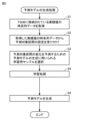
図12は、実施形態に基づく予測モデルの評価について説明するフロー図である。図12を参照して、サポート装置200は、予測モデルを取得する(ステップS10)。次に、サポート装置200は、取得した予測モデルの決定木構造を解析する(ステップS12)。具体的には、予測モデルの葉ノードの特性値を算出する。より具体的には、葉ノードの特性値として木の深さおよび葉ノードに対応付けられる分布図の面積を算出する。
Fig. 12 is a flow diagram for explaining the evaluation of a prediction model based on an embodiment. Referring to Fig. 12, the
次に、サポート装置200は、モデル評価画面を表示する(ステップS14)。
そして、処理を終了する(エンド)。
Next, the
Then, the process ends (END).
図13は、実施形態に基づく予測モデルの木構造の具体例について説明する図である。図13を参照して、予測モデルの木構造が示されている。具体的には、予測モデルは、入力データ(説明変数x1あるいはx2)に対して、出力データ(目的変数Y0~Y4)を推定する。 Figure 13 is a diagram illustrating a specific example of a tree structure of a prediction model based on an embodiment. With reference to Figure 13, the tree structure of the prediction model is shown. Specifically, the prediction model estimates output data (objective variables Y0 to Y4) for input data (explanatory variables x1 or x2).
根ノードR0において、X1<6が判定される。根ノードR0において、X1<6を満たす場合には、葉ノードR1に進む。葉ノードR1は、目的変数Y0に対応する。一方、根ノードR0において、6≦X1を満たす場合には、中間ノードR5に進む。中間ノードR5において、X2<10が判定される。中間ノードR5において、X2<10を満たす場合には、中間ノードR3に進む。中間ノードR5において、10≦X2を満たす場合には、中間ノードR8に進む。 At the root node R0, it is determined whether X1<6. If X1<6 is satisfied at the root node R0, proceed to the leaf node R1. The leaf node R1 corresponds to the objective variable Y0. On the other hand, if 6≦X1 is satisfied at the root node R0, proceed to the intermediate node R5. At the intermediate node R5, it is determined whether X2<10 is satisfied. If X2<10 is satisfied at the intermediate node R5, proceed to the intermediate node R3. If 10≦X2 is satisfied at the intermediate node R5, proceed to the intermediate node R8.
中間ノードR3において、X1<4が判定される。中間ノードR3において、X1<4を満たす場合には、葉ノードR2に進む。葉ノードR2は、目的変数Y1に対応する。中間ノードR3において、4≦X1を満たす場合には、葉ノードR4に進む。葉ノードR4は、目的変数Y2に対応する。 At intermediate node R3, it is determined whether X1<4. If X1<4 is satisfied at intermediate node R3, proceed to leaf node R2. Leaf node R2 corresponds to objective variable Y1. If 4≦X1 is satisfied at intermediate node R3, proceed to leaf node R4. Leaf node R4 corresponds to objective variable Y2.
中間ノードR8において、X1<3が判定される。中間ノードR8において、X1<3を満たす場合には、葉ノードR6に進む。葉ノードR6は、目的変数Y3に対応する。中間ノードR8において、3≦X1を満たす場合には、葉ノードR7に進む。葉ノードR7は、目的変数Y4に対応する。 At intermediate node R8, it is determined whether X1<3. If X1<3 is satisfied at intermediate node R8, the process proceeds to leaf node R6. Leaf node R6 corresponds to objective variable Y3. If 3≦X1 is satisfied at intermediate node R8, the process proceeds to leaf node R7. Leaf node R7 corresponds to objective variable Y4.
図14は、実施形態に基づく予測モデルの分布図の具体例について説明する図である。図14を参照して、予測モデルは、入力データ(横軸x1、縦軸x2)に対して、出力データ(目的変数Y0~Y4)を推定する。 Figure 14 is a diagram illustrating a specific example of a distribution diagram of a prediction model based on an embodiment. Referring to Figure 14, the prediction model estimates output data (objective variables Y0 to Y4) for input data (horizontal axis x1, vertical axis x2).
分布図に示されるように、目的変数Y0の正規化面積は、0.5である。目的変数Y1の正規化面積は0.16である。目的変数Y2の正規化面積は0.08である。目的変数Y3の正規化面積は0.13である。目的変数Y4の正規化面積は0.13である。 As shown in the distribution diagram, the normalized area of objective variable Y0 is 0.5. The normalized area of objective variable Y1 is 0.16. The normalized area of objective variable Y2 is 0.08. The normalized area of objective variable Y3 is 0.13. The normalized area of objective variable Y4 is 0.13.
図15は、実施形態に基づくモデル評価画面について説明する図である。図15を参照して、モデル評価画面250が示されている。モデル評価画面には、予測モデルの入力モデルファイルを入力欄260が設けられている。ユーザは、入力欄260で予測モデルのデータが格納されたファイルFを選択した場合が示されている。任意のファイルを選択することにより、予測モデルの木構造の特性を解析することが可能である。
FIG. 15 is a diagram illustrating a model evaluation screen based on an embodiment. Referring to FIG. 15, a
モデル評価画面250は、判定モードを選択する選択項目261が設けられている。一例として、選択項目として「木の深さ」と、「正規化面積」を選択することが可能である。なお、これに限られず、種々の判定方式に従って、選択項目を増加させることも当然に可能である。本例においては、「木の深さ」が選択されている場合が示されている。
The
モデル評価画面250は、設定閾値を設定する入力欄262が設けられている。当該入力欄は、判定モードに応じて切り替えるようにしてもよい。一例として、「木の深さ」の設定閾値として「2」が設定されている場合が示されている。
The
モデル評価画面250は、予測モデルの木構造の特性の解析結果として「Tree View」と、分布図とをそれぞれ選択可能なタブ264と、タブ270が設けられている。一例としてタブ264が選択されている場合が示されている。
The
本例においては、画面266に、図13で説明したのと同様の木構造が示されている。当該木構造を確認することにより予測モデルの特性を容易に把握することが可能である。
In this example, a tree structure similar to that described in FIG. 13 is displayed on
具体的には、最小の木の深さ「1」であることが示されており、設定閾値「2」を下回っていることを把握することが可能である。また、木構造によりばらつきの程度の容易に把握することが可能である。 Specifically, it is shown that the minimum tree depth is "1", which is below the set threshold of "2". In addition, the tree structure makes it easy to understand the degree of variation.
モデル評価画面250は、解析結果として「10<x1<20の範囲のデータがモデルの精度向上に寄与します。」のメッセージ268が示されている。当該範囲のデータを追加することにより、一例として図11で説明したように予測モデルの精度を良くすることが可能である。
The
図16は、実施形態に基づく別のモデル評価画面について説明する図である。図16を参照して、モデル評価画面250が示されている。モデル評価画面には、予測モデルの入力モデルファイルを入力欄260が設けられている。ユーザは、入力欄260で予測モデルのデータが格納されたファイルFを選択した場合が示されている。任意のファイルを選択することにより、予測モデルの木構造の特性を解析することが可能である。
FIG. 16 is a diagram illustrating another model evaluation screen based on an embodiment. Referring to FIG. 16, a
モデル評価画面250は、判定モードを選択する選択項目261が設けられている。一例として、選択項目として「木の深さ」と、「正規化面積」を選択することが可能である。なお、これに限られず、種々の判定方式に従って、選択項目を増加させることも当然に可能である。本例においては、「正規化面積」が選択されている場合が示されている。
The
モデル評価画面250は、設定閾値を設定する入力欄262が設けられている。当該入力欄は、判定モードに応じて切り替えるようにしてもよい。一例として、「正規化面積」の設定閾値として「0.3」が設定されている場合が示されている。
The
モデル評価画面250は、予測モデルの木構造の特性の解析結果として「Tree View」と、分布図とをそれぞれ選択可能なタブ264と、タブ270が設けられている。一例としてタブ270が選択されている場合が示されている。
The
本例においては、画面266に、図14で説明したのと同様の分布図が示されている。当該分布図を確認することにより予測モデルの特性を容易に把握することが可能である。
In this example, a distribution diagram similar to that described in FIG. 14 is displayed on
具体的には、最大の正規化後面積「0.5」であることが示されており、設定閾値「0.3」を上回っていることを把握することが可能である。また、分布図によりばらつきの程度の容易に把握することが可能である。 Specifically, it is shown that the maximum normalized area is "0.5," which is greater than the set threshold of "0.3." In addition, the distribution diagram makes it easy to grasp the degree of variation.
モデル評価画面250は、解析結果として「10<x1<20の範囲のデータがモデルの精度向上に寄与します。」のメッセージ268が示されている。当該範囲のデータを追加することにより、一例として図11で説明したように予測モデルの精度を良くすることが可能である。
The
なお、本例においては、2つの説明変数に対して目的変数を予測する予測モデルについて説明したが、2つに限られずさらに複数(n≧2)の説明変数に対して目的変数を予測する予測モデルについても同様に適用することが可能である。 In this example, a prediction model that predicts a dependent variable for two explanatory variables has been described, but the same can be applied to a prediction model that predicts a dependent variable for more than two explanatory variables (n≧2).
<F.具体例>
図17は、実施形態に基づく予測システム1の適用例を説明する図である。図17(A)を参照して、プレス機30のワーク材料特性のばらつきに基づくプレス結果について説明する図である。具体的には、プレス機30の押し込み位置がワーク材料特性としてワークが硬い場合と、ワークが柔らかい場合とでそれぞれ異なる場合が示されている。
< F . Specific Examples>
17A and 17B are diagrams for explaining application examples of the
図17(B)を参照して、予測システム1は、予測モデル140を用いて押し込み位置(予測値)を算出して、予測値と目標位置軌道との差に基づいてプレス機30に対する操作量を補正する。その結果、予期しない要因変動による不良品の発生を抑制でき、ワーク31に何らかのばらつきがあっても、品質を安定化できる。
Referring to FIG. 17(B), the
この点で、予測モデル140の精度を向上させることにより、より品質の安定化を図ることが可能となる。
In this regard, by improving the accuracy of the
図18は、実施形態に基づく予測モデルの追加学習について説明する図である。図18(A)を参照して、追加学習前のプレス機30のワーク材料特性のばらつきに基づくプレス結果と、当該プレス結果に基づく予測モデルの木構造が示されている。上記で説明したように、例えば予測モデルの木構造の解析結果として、点「a1」を通るデータが少ないことにより木の深さが浅いものとする。したがって、点「a1」を通るデータを探索することにより、予測モデルの精度をさらに向上させることが可能となる。点「a1」を通るデータの探索は、過去のデータベースに格納されているデータから取得するようにしても良いし、実機を複数回動作させた際に取得するようにしても良い。
Figure 18 is a diagram for explaining additional learning of a prediction model based on an embodiment. Referring to Figure 18 (A), the press results based on the variability of the workpiece material properties of the
図18(B)を参照して、点「a1」を通る別のデータを取得した場合が示されている。当該データを追加学習することにより、予測モデルの木構造は変化する。そして、本例においては、木の深さのばらつきを抑制して、予測モデルの精度をさらに向上させることが可能となる。 Referring to FIG. 18(B), a case is shown in which another data passing through point "a1" is acquired. By additionally learning this data, the tree structure of the prediction model changes. In this example, it is possible to suppress the variation in the tree depth and further improve the accuracy of the prediction model.
<G.変形例>
上述の説明においては、時間変化を予測する予測システム1について説明したが、制御対象などに生じる異常を検知する異常検知システムにも適用可能である。
< G . Modifications>
In the above explanation, the
図19は、本実施の形態の変形例に係る異常検知システム1Aの概要構成を示す模式図である。図19を参照して、異常検知システム1Aは、制御対象から取得された生データ40から学習用サンプルを選択し(サンプル選択42)、選択された学習用サンプルに基づいて異常検知モデル44が生成される。そして、生成された異常検知モデル44を用いて、異常検知の運用46が実行される。
Fig. 19 is a schematic diagram showing the general configuration of an
異常検知モデル44は、制御対象が通常の状態とは異なる状態を示していることを検知することを主題とするものであり、制御対象から収集される生データ(時系列データ)を用いて、収集された生データに適合する異常検知モデル44が生成される。異常検知モデル44に通常とは異なる生データが入力されることで、通常とは異なる状態であることを示す値が出力されることで、制御対象に何らかの異常が発生していることを検知できる。このような異常検知モデル44に用いられる学習用サンプルについては、上述のステップS3と同様に、変化パターンが互いに異なる生データを採用することが好ましい。
The
図20は、本実施の形態の変形例に係る異常検知システム1Aの具体例について説明する図である。
Figure 20 is a diagram illustrating a specific example of an
図20(A)を参照して、生データとして正常、異常A、異常Bの波形パターンが示されている。 Referring to Figure 20 (A), the waveform patterns of normal, abnormal A, and abnormal B are shown as raw data.
図20(B)正常、異常A、異常Bの波形パターンは、波形の特徴量として波形の平均値および波形の分散の値を用いて分類される。具体的には、縦軸F1は、波形の平均値であり、横軸F2は、波形の分散値である。 Figure 20 (B) Normal, abnormal A, and abnormal B waveform patterns are classified using the average value and variance value of the waveform as waveform features. Specifically, the vertical axis F1 is the average value of the waveform, and the horizontal axis F2 is the variance value of the waveform.
図20(C)および(D)は、上記の分類パターンをサンプルとして選択した場合の異常検知モデル44を説明する図である。解析モジュール242は、上記で説明したのと同様に、波形パターンをサンプルとして選択して、異常検知モデル44を生成する。
Figures 20(C) and (D) are diagrams explaining the
図20(C)は、異常検知モデル44の正常、異常Aおよび異常Bの分布図を示す。図20(D)は、異常検知モデル44の木構造を示す。
Figure 20 (C) shows a distribution diagram of normal, abnormality A, and abnormality B in the
異常検知モデル44は、入力データ(説明変数F1あるいはF2)に対して、出力データ(目的変数「正常」、「異常A」、「異常B」)を推定する。
The
根ノードR10において、F2<aが判定される。根ノードR10において、F2<aを満たす場合には、葉ノードR11に進む。葉ノードR11は、目的変数「正常」に対応する。一方、根ノードR10において、a≦F2を満たす場合には、中間ノードR15に進む。中間ノードR15において、F1<dが判定される。中間ノードR15において、F1<dを満たす場合には、中間ノードR13に進む。中間ノードR15において、d≦F1を満たす場合には、中間ノードR18に進む。 At the root node R10, it is determined whether F2<a. If F2<a is satisfied at the root node R10, the process proceeds to the leaf node R11. The leaf node R11 corresponds to the objective variable "normal". On the other hand, if a≦F2 is satisfied at the root node R10, the process proceeds to the intermediate node R15. At the intermediate node R15, it is determined whether F1<d is satisfied. If F1<d is satisfied at the intermediate node R15, the process proceeds to the intermediate node R13. If d≦F1 is satisfied at the intermediate node R15, the process proceeds to the intermediate node R18.
中間ノードR13において、F2<bが判定される。中間ノードR13において、F2<bを満たす場合には、葉ノードR12に進む。葉ノードR12は、目的変数「異常B」に対応する。中間ノードR13において、b≦F2を満たす場合には、葉ノードR14に進む。葉ノードR14は、目的変数「異常A」に対応する。 At intermediate node R13, it is determined whether F2<b. If F2<b is satisfied at intermediate node R13, the process proceeds to leaf node R12. Leaf node R12 corresponds to the objective variable "abnormality B". If b≦F2 is satisfied at intermediate node R13, the process proceeds to leaf node R14. Leaf node R14 corresponds to the objective variable "abnormality A".
中間ノードR18において、F2<cが判定される。中間ノードR18において、F2<cを満たす場合には、葉ノードR16に進む。葉ノードR16は、目的変数「異常A」に対応する。中間ノードR18において、c≦F2を満たす場合には、葉ノードR17に進む。葉ノードR17は、目的変数「異常B」に対応する。 At intermediate node R18, it is determined whether F2<c. If F2<c is satisfied at intermediate node R18, the process proceeds to leaf node R16. Leaf node R16 corresponds to the objective variable "abnormality A". If c≦F2 is satisfied at intermediate node R18, the process proceeds to leaf node R17. Leaf node R17 corresponds to the objective variable "abnormality B".
図21は、本実施の形態の変形例に係る異常検知システム1Aの評価の概念図である。図21(A)を参照して、図20(C)および(D)の異常検知モデル44の決定木構造を解析した場合に、「正常」の葉ノードの木の深さが浅いことが分かる。また、分布図を確認した場合に、正規化面積が大きいことが分かる。
Figure 21 is a conceptual diagram of an evaluation of
したがって、上記の方式に従ってモデル評価画面を表示することにより、異常検知モデルの特性を容易に把握することが可能である。 Therefore, by displaying the model evaluation screen according to the above method, it is possible to easily understand the characteristics of the anomaly detection model.
また、異常検知モデル44の精度を向上させるためにどのデータが必要かも容易に把握することが可能である。具体的には、波形の分散値F2<aである。
It is also easy to understand what data is needed to improve the accuracy of the
図21(B)を参照して、新たに発生した「異常A」のデータが示されている。当該データを追加学習することにより異常検知モデル44の精度を向上させることが可能である。
Referring to FIG. 21(B), data on a newly-occurring "abnormality A" is shown. By additionally learning this data, it is possible to improve the accuracy of the
図22は、本実施の形態の変形例に係る異常検知モデルの追加学習について説明する図である。図22(A)、(B)を参照して、新たに発生した「異常A」のデータを追加学習することにより、異常検知モデル44が更新された場合が示されている。
Figure 22 is a diagram explaining additional learning of an anomaly detection model according to a modified example of this embodiment. Referring to Figures 22 (A) and (B), a case is shown in which
図22(A)は、更新された異常検知モデル44の分布図である。図22(B)は、更新された異常検知モデルの木構造である。
Figure 22 (A) is a distribution diagram of the updated
上記においては、主に決定木に代表される木構造の学習アルゴリズムに基づく予測モデルを生成する場合について説明したが、決定木に限られず、木構造であれば他の学習アルゴリズムを用いた予測モデルにも同様に適用することが可能である。 The above describes the case of generating a predictive model based on a tree-structured learning algorithm, such as a decision tree, but it is not limited to decision trees and can be applied to predictive models using other learning algorithms as long as they are tree-structured.
<H.付記>
上述したような本実施の形態は、以下のような技術思想を含む。
< H . Notes>
The present embodiment as described above includes the following technical idea.
[構成1]
予測システム(1)は、制御対象を制御するための制御演算を実行する制御演算部(164)と、制御演算部が参照可能な状態値のうち1または複数の状態値からなる実績値を予測モデルに入力することで予測値を取得する予測値取得部(156)と、木構造の学習アルゴリズムに基づく予測モデルを生成する予測モデル生成部(2262)と、予測モデルを評価する予測モデル評価部(2264)とを備える。予測モデル評価部は、予測モデルの木構造の特性を解析する解析部(244)と、解析部の解析結果に基づいて予測モデルを評価する評価部(242)とを含む。
[Configuration 1]
The prediction system (1) includes a control calculation unit (164) that executes control calculation for controlling a control target, a prediction value acquisition unit (156) that acquires a prediction value by inputting an actual value consisting of one or more state values among state values that the control calculation unit can refer to into a prediction model, a prediction model generation unit (2262) that generates a prediction model based on a tree-structured learning algorithm, and a prediction model evaluation unit (2264) that evaluates the prediction model. The prediction model evaluation unit includes an analysis unit (244) that analyzes characteristics of the tree structure of the prediction model, and an evaluation unit (242) that evaluates the prediction model based on the analysis result of the analysis unit.
[構成2]
予測モデル評価部は、予測モデルを評価する評価の種別および基準値を設定する評価設定部(261,262)をさらに含む。
[Configuration 2]
The prediction model evaluation unit further includes an evaluation setting unit (261, 262) that sets the type of evaluation and a reference value for evaluating the prediction model.
[構成3]
評価部(238)は、予測モデルの評価結果を表示部に表示する。
[Configuration 3]
The evaluation unit (238) displays the evaluation results of the prediction model on the display unit.
[構成4]
予測モデル生成部は、予測モデルの評価結果に対応する学習用サンプルに基づいて予測モデルを更新する。
[Configuration 4]
The prediction model generation unit updates the prediction model based on the learning sample corresponding to the evaluation result of the prediction model.
[構成5]
情報処理装置(200)は、制御装置(100)に接続される情報処理装置であって、制御装置は、制御対象を制御するための制御演算を実行する制御演算部(164)と、制御演算部が参照可能な状態値のうち1または複数の状態値からなる実績値を予測モデルに入力することで予測値を取得する予測値取得部(156)とを備える。情報処理装置は、木構造の学習アルゴリズムに基づく予測モデルを生成する予測モデル生成部(2262)と、予測モデルを評価する予測モデル評価部(2264)とを備える。予測モデル評価部は、予測モデルの木構造の特性を解析する解析部(244)と、解析部の解析結果に基づいて予測モデルを評価する評価部(242)とを含む。
[Configuration 5]
The information processing device (200) is an information processing device connected to a control device (100), and the control device includes a control calculation unit (164) that executes control calculation for controlling a control target, and a predicted value acquisition unit (156) that acquires a predicted value by inputting an actual value consisting of one or more state values among state values that the control calculation unit can refer to into a prediction model. The information processing device includes a prediction model generation unit (2262) that generates a prediction model based on a tree-structured learning algorithm, and a prediction model evaluation unit (2264) that evaluates the prediction model. The prediction model evaluation unit includes an analysis unit (244) that analyzes the characteristics of the tree structure of the prediction model, and an evaluation unit (242) that evaluates the prediction model based on the analysis result of the analysis unit.
[構成6]
情報処理プログラムは、制御装置(100)に接続されるコンピュータで実行される情報処理プログラムであって、制御装置は、制御対象を制御するための制御演算を実行する制御演算部(164)と、制御演算部が参照可能な状態値のうち1または複数の状態値からなる実績値を予測モデルに入力することで予測値を取得する予測値取得部(156)とを備える。情報処理プログラムは、コンピュータに、木構造の学習アルゴリズムに基づく予測モデルを生成するステップ(S6)と、予測モデルを評価するステップ(S12)とを実行させる。予測モデルを評価するステップは、予測モデルの木構造の特性を解析するステップと、解析結果に基づいて予測モデルを評価するステップとを含む。
[Configuration 6]
The information processing program is executed by a computer connected to a control device (100), and the control device includes a control calculation unit (164) that executes control calculations for controlling a control target, and a predicted value acquisition unit (156) that acquires a predicted value by inputting an actual value consisting of one or more state values among state values that the control calculation unit can refer to into a prediction model. The information processing program causes the computer to execute a step (S6) of generating a prediction model based on a tree-structured learning algorithm, and a step (S12) of evaluating the prediction model. The step of evaluating the prediction model includes a step of analyzing characteristics of the tree structure of the prediction model, and a step of evaluating the prediction model based on the analysis results.
<K.利点>
実施形態に基づく予測システムにおいては、簡易に予測モデルを評価できるので、実際の運用に好適な予測モデルを容易に生成できる。
K. Advantages
In the prediction system based on the embodiment, a prediction model can be easily evaluated, so that a prediction model suitable for actual operation can be easily generated.
今回開示された実施の形態はすべての点で例示であって制限的なものではないと考えられるべきである。本開示の範囲は、上記した説明ではなく、特許請求の範囲によって示され、特許請求の範囲と均等の意味および範囲内でのすべての変更が含まれることが意図される。 The embodiments disclosed herein should be considered to be illustrative and not restrictive in all respects. The scope of the present disclosure is indicated by the claims, not by the above description, and is intended to include all modifications within the meaning and scope of the claims.
1 予測システム、1A 異常検知システム、2,4 フィールドバス、6 上位ネットワーク、10 フィールド装置群、14 リレー群、100 制御装置、102,202 プロセッサ、104 チップセット、106,206 主記憶装置、108,208 二次記憶装置、110,214 上位ネットワークコントローラ、112,212 コントローラ、114 メモリカードインターフェイス、116 メモリカード、118,120 フィールドバスコントローラ、122 内部バスコントローラ、132 記憶領域、134 エクスポートモジュール、140 予測モデル、144 参照軌道、150 エンジン、152 変数、154 ユーザプログラム、156 予測値取得コード、158 誤差評価コード、160 追加学習コード、162 書き込みコード、164 制御演算コード、200 サポート装置、204 光学ドライブ、205 記録媒体、216 入力部、218 表示部、220 バス、222 開発プログラム、224 インターフェイスプログラム、226 解析プログラム、230 ユーザインターフェイス、232 スクリプトエンジン、234 設定ファイル、236 入出力管理モジュール、238 画面表示モジュール、240 グラフライブラリ、242 解析モジュール、244 解析ライブラリ、250 モデル評価画面、260,262 入力欄、261 選択項目、264,270 タブ、266 画面、268 メッセージ、300 上位サーバ、400 表示装置、2262 モデル生成モジュール、2264 評価モジュール。 1 Prediction system, 1A Anomaly detection system, 2, 4 Field bus, 6 Upper network, 10 Field device group, 14 Relay group, 100 Control device, 102, 202 Processor, 104 Chip set, 106, 206 Main memory, 108, 208 Secondary memory, 110, 214 Upper network controller, 112, 212 Controller, 114 Memory card interface, 116 Memory card, 118, 120 Field bus controller, 122 Internal bus controller, 132 Memory area, 134 Export module, 140 Prediction model, 144 Reference trajectory, 150 Engine, 152 Variables, 154 User program, 156 Prediction value acquisition code, 158 Error evaluation code, 160 Additional learning code, 162 Write code, 164 Control operation code, 200 Support device, 204 Optical drive, 205 Recording medium, 216 input unit, 218 display unit, 220 bus, 222 development program, 224 interface program, 226 analysis program, 230 user interface, 232 script engine, 234 configuration file, 236 input/output management module, 238 screen display module, 240 graph library, 242 analysis module, 244 analysis library, 250 model evaluation screen, 260, 262 input field, 261 selection item, 264, 270 tab, 266 screen, 268 message, 300 host server, 400 display device, 2262 model generation module, 2264 evaluation module.
Claims (6)
前記制御演算部が参照可能な状態値のうち1または複数の状態値からなる実績値を予測
モデルに入力することで予測値を取得する予測値取得部と、
木構造の学習アルゴリズムに基づく前記予測モデルを生成する予測モデル生成部と、
前記予測モデルを評価する予測モデル評価部とを備え、
前記予測モデル評価部は、
前記予測モデルの木構造の特性を解析する解析部と、
前記解析部の解析結果に基づいて前記予測モデルを評価する評価部とを含み、
前記解析部は、前記予測モデルの木構造の複数の葉ノードの特性値として当該複数の葉ノードの分布図の面積をそれぞれ算出し、
前記評価部は、算出された前記複数の葉ノードの分布図の面積に基づいて前記予測モデルを評価する、予測システム。 A control calculation unit that executes a control calculation for controlling a control target;
a prediction value acquisition unit that acquires a prediction value by inputting an actual value consisting of one or more state values among state values that the control calculation unit can refer to into a prediction model;
a prediction model generation unit that generates the prediction model based on a tree-structured learning algorithm;
A prediction model evaluation unit that evaluates the prediction model,
The prediction model evaluation unit,
an analysis unit that analyzes characteristics of a tree structure of the prediction model;
an evaluation unit that evaluates the prediction model based on an analysis result of the analysis unit ;
the analysis unit calculates areas of distribution diagrams of a plurality of leaf nodes as characteristic values of the plurality of leaf nodes in the tree structure of the prediction model,
A prediction system, wherein the evaluation unit evaluates the prediction model based on the calculated area of the distribution diagram of the multiple leaf nodes .
る評価設定部をさらに含む、請求項1に記載の予測システム。 The prediction system according to claim 1 , wherein the prediction model evaluation unit further includes an evaluation setting unit that sets a type of evaluation and a reference value for evaluating the prediction model.
システム。 The prediction system according to claim 1 , wherein the evaluation unit displays the evaluation result of the prediction model on a display unit.
いて前記予測モデルを更新する、請求項1~3のいずれか1項に記載の予測システム。 The prediction system according to claim 1 , wherein the prediction model generation unit updates the prediction model based on a learning sample corresponding to an evaluation result of the prediction model.
前記情報処理装置は、
木構造の学習アルゴリズムに基づく前記予測モデルを生成する予測モデル生成部と、
前記予測モデルを評価する予測モデル評価部とを備え、
前記予測モデル評価部は、
前記予測モデルの木構造の特性を解析する解析部と、
前記解析部の解析結果に基づいて前記予測モデルを評価する評価部とを含み、
前記解析部は、前記予測モデルの木構造の複数の葉ノードの特性値として当該複数の葉ノードの分布図の面積をそれぞれ算出し、
前記評価部は、算出された前記複数の葉ノードの分布図の面積に基づいて前記予測モデルを評価する、情報処理装置。 An information processing device connected to a control device, the control device comprising: a control calculation unit that executes control calculations for controlling a control target; and a predicted value acquisition unit that acquires a predicted value by inputting an actual value consisting of one or more state values among state values that the control calculation unit can refer to into a prediction model;
The information processing device includes:
a prediction model generation unit that generates the prediction model based on a tree-structured learning algorithm;
A prediction model evaluation unit that evaluates the prediction model,
The prediction model evaluation unit,
an analysis unit that analyzes characteristics of a tree structure of the prediction model;
an evaluation unit that evaluates the prediction model based on an analysis result of the analysis unit ;
the analysis unit calculates areas of distribution diagrams of a plurality of leaf nodes as characteristic values of the plurality of leaf nodes in the tree structure of the prediction model,
The evaluation unit evaluates the prediction model based on the calculated area of a distribution diagram of the multiple leaf nodes .
前記情報処理プログラムは、前記コンピュータに、
木構造の学習アルゴリズムに基づく前記予測モデルを生成するステップと、
前記予測モデルを評価するステップとを実行させ、
前記予測モデルを評価するステップは、
前記予測モデルの木構造の特性を解析するステップと、
解析結果に基づいて前記予測モデルを評価するステップとを含み、
前記解析するステップは、前記予測モデルの木構造の複数の葉ノードの特性値として当該複数の葉ノードの分布図の面積をそれぞれ算出するステップを含み、
前記評価するステップは、算出された前記複数の葉ノードの分布図の面積に基づいて前記予測モデルを評価するステップを含む、情報処理プログラム。 An information processing program executed by a computer connected to a control device, the control device comprising: a control calculation unit that executes control calculations for controlling a control target; and a predicted value acquisition unit that acquires a predicted value by inputting an actual value consisting of one or more state values among state values that the control calculation unit can refer to into a prediction model;
The information processing program is configured to:
generating the predictive model based on a tree-structured learning algorithm;
and evaluating the predictive model;
The step of evaluating the predictive model comprises:
analyzing a property of the tree structure of the predictive model;
and evaluating the predictive model based on the analysis results ;
the analyzing step includes a step of calculating areas of a distribution diagram of a plurality of leaf nodes as characteristic values of the plurality of leaf nodes in the tree structure of the prediction model,
An information processing program, wherein the evaluating step includes a step of evaluating the prediction model based on the calculated area of a distribution diagram of the plurality of leaf nodes .
Priority Applications (2)
| Application Number | Priority Date | Filing Date | Title |
|---|---|---|---|
| JP2021023287A JP7556306B2 (en) | 2021-02-17 | 2021-02-17 | Prediction system, information processing device, and information processing program |
| PCT/JP2021/047194 WO2022176375A1 (en) | 2021-02-17 | 2021-12-21 | Prediction system, information processing device, and information processing program |
Applications Claiming Priority (1)
| Application Number | Priority Date | Filing Date | Title |
|---|---|---|---|
| JP2021023287A JP7556306B2 (en) | 2021-02-17 | 2021-02-17 | Prediction system, information processing device, and information processing program |
Publications (2)
| Publication Number | Publication Date |
|---|---|
| JP2022125608A JP2022125608A (en) | 2022-08-29 |
| JP7556306B2 true JP7556306B2 (en) | 2024-09-26 |
Family
ID=82930551
Family Applications (1)
| Application Number | Title | Priority Date | Filing Date |
|---|---|---|---|
| JP2021023287A Active JP7556306B2 (en) | 2021-02-17 | 2021-02-17 | Prediction system, information processing device, and information processing program |
Country Status (2)
| Country | Link |
|---|---|
| JP (1) | JP7556306B2 (en) |
| WO (1) | WO2022176375A1 (en) |
Families Citing this family (1)
| Publication number | Priority date | Publication date | Assignee | Title |
|---|---|---|---|---|
| KR20260033900A (en) * | 2024-09-03 | 2026-03-10 | 주식회사 엘지에너지솔루션 | Apparatus and method for evaluating performance of anomaly detection model |
Citations (3)
| Publication number | Priority date | Publication date | Assignee | Title |
|---|---|---|---|---|
| WO2017168458A1 (en) | 2016-03-28 | 2017-10-05 | 日本電気株式会社 | Prediction model selection system, prediction model selection method, and prediction model selection program |
| JP2018177869A (en) | 2017-04-05 | 2018-11-15 | 新日鐵住金株式会社 | Apparatus for predicting extrusion load of coke oven, extrusion load prediction method, computer program and computer readable storage medium |
| JP2020139175A (en) | 2019-02-26 | 2020-09-03 | Jfeスチール株式会社 | Time-series event prediction method, plating adhesion amount control method, hot-dip plated steel strip manufacturing method, time-series event prediction device, plating adhesion amount control device and plating adhesion amount control program |
-
2021
- 2021-02-17 JP JP2021023287A patent/JP7556306B2/en active Active
- 2021-12-21 WO PCT/JP2021/047194 patent/WO2022176375A1/en not_active Ceased
Patent Citations (3)
| Publication number | Priority date | Publication date | Assignee | Title |
|---|---|---|---|---|
| WO2017168458A1 (en) | 2016-03-28 | 2017-10-05 | 日本電気株式会社 | Prediction model selection system, prediction model selection method, and prediction model selection program |
| JP2018177869A (en) | 2017-04-05 | 2018-11-15 | 新日鐵住金株式会社 | Apparatus for predicting extrusion load of coke oven, extrusion load prediction method, computer program and computer readable storage medium |
| JP2020139175A (en) | 2019-02-26 | 2020-09-03 | Jfeスチール株式会社 | Time-series event prediction method, plating adhesion amount control method, hot-dip plated steel strip manufacturing method, time-series event prediction device, plating adhesion amount control device and plating adhesion amount control program |
Also Published As
| Publication number | Publication date |
|---|---|
| WO2022176375A1 (en) | 2022-08-25 |
| JP2022125608A (en) | 2022-08-29 |
Similar Documents
| Publication | Publication Date | Title |
|---|---|---|
| JP7413742B2 (en) | Prediction system, information processing device and information processing program | |
| JP6903976B2 (en) | Control system | |
| JP2019520659A (en) | Computer system and method for monitoring key performance indicators (KPIs) using time series pattern models | |
| WO2022030041A1 (en) | Prediction system, information processing device, and information processing program | |
| JP5125875B2 (en) | PID controller tuning apparatus, PID controller tuning program, and PID controller tuning method | |
| JP7556306B2 (en) | Prediction system, information processing device, and information processing program | |
| JP7151312B2 (en) | control system | |
| JP7639574B2 (en) | Prediction system, information processing device, and information processing program | |
| JP7571613B2 (en) | Information processing device, information processing program, and information processing method | |
| JP7749952B2 (en) | Control system, model generation method, and model generation program | |
| US20170277142A1 (en) | Process control system performance analysis using scenario data | |
| JP7676986B2 (en) | Information processing device, model generation program, and model generation method | |
| JP2023151888A (en) | Prediction systems, control devices and control programs | |
| JP7524784B2 (en) | Information processing device, control system, and report output method | |
| JP2024060240A (en) | Information processing device, information processing method, and program | |
| JP2023151886A (en) | Information processing device and information processing program | |
| JP2023151755A (en) | Information processing device and information processing program | |
| TWI843084B (en) | Control system, information processing method and information processing device | |
| JP2024118777A (en) | Information processing device, information processing method, and information processing program | |
| JP2022142415A (en) | Information processing device, parameter calculation method, and parameter calculation program |
Legal Events
| Date | Code | Title | Description |
|---|---|---|---|
| A621 | Written request for application examination |
Free format text: JAPANESE INTERMEDIATE CODE: A621 Effective date: 20231212 |
|
| A131 | Notification of reasons for refusal |
Free format text: JAPANESE INTERMEDIATE CODE: A131 Effective date: 20240625 |
|
| A521 | Request for written amendment filed |
Free format text: JAPANESE INTERMEDIATE CODE: A523 Effective date: 20240726 |
|
| TRDD | Decision of grant or rejection written | ||
| A01 | Written decision to grant a patent or to grant a registration (utility model) |
Free format text: JAPANESE INTERMEDIATE CODE: A01 Effective date: 20240813 |
|
| A61 | First payment of annual fees (during grant procedure) |
Free format text: JAPANESE INTERMEDIATE CODE: A61 Effective date: 20240826 |
|
| R150 | Certificate of patent or registration of utility model |
Ref document number: 7556306 Country of ref document: JP Free format text: JAPANESE INTERMEDIATE CODE: R150 |