JP7529635B2 - Upper segment and oil ring - Google Patents
Upper segment and oil ring Download PDFInfo
- Publication number
- JP7529635B2 JP7529635B2 JP2021161868A JP2021161868A JP7529635B2 JP 7529635 B2 JP7529635 B2 JP 7529635B2 JP 2021161868 A JP2021161868 A JP 2021161868A JP 2021161868 A JP2021161868 A JP 2021161868A JP 7529635 B2 JP7529635 B2 JP 7529635B2
- Authority
- JP
- Japan
- Prior art keywords
- upper segment
- inner circumferential
- apex
- segment
- cross
- Prior art date
- Legal status (The legal status is an assumption and is not a legal conclusion. Google has not performed a legal analysis and makes no representation as to the accuracy of the status listed.)
- Active
Links
- 230000002093 peripheral effect Effects 0.000 claims description 65
- 238000002485 combustion reaction Methods 0.000 claims description 40
- 125000006850 spacer group Chemical group 0.000 claims description 22
- 239000003921 oil Substances 0.000 description 75
- 230000004048 modification Effects 0.000 description 10
- 238000012986 modification Methods 0.000 description 10
- 238000007789 sealing Methods 0.000 description 9
- 230000000052 comparative effect Effects 0.000 description 8
- 230000006835 compression Effects 0.000 description 3
- 238000007906 compression Methods 0.000 description 3
- 230000000630 rising effect Effects 0.000 description 3
- 238000005516 engineering process Methods 0.000 description 2
- 239000010687 lubricating oil Substances 0.000 description 2
- 238000007790 scraping Methods 0.000 description 2
- 229910000639 Spring steel Inorganic materials 0.000 description 1
- 239000011248 coating agent Substances 0.000 description 1
- 238000000576 coating method Methods 0.000 description 1
- 239000000567 combustion gas Substances 0.000 description 1
- 238000007739 conversion coating Methods 0.000 description 1
- 238000010586 diagram Methods 0.000 description 1
- 230000000694 effects Effects 0.000 description 1
- 238000011156 evaluation Methods 0.000 description 1
- 239000007789 gas Substances 0.000 description 1
- 238000004519 manufacturing process Methods 0.000 description 1
- 239000000463 material Substances 0.000 description 1
- 239000010705 motor oil Substances 0.000 description 1
- 238000005121 nitriding Methods 0.000 description 1
- 230000000737 periodic effect Effects 0.000 description 1
- 238000000926 separation method Methods 0.000 description 1
- 229910001220 stainless steel Inorganic materials 0.000 description 1
- 239000010935 stainless steel Substances 0.000 description 1
- 239000000126 substance Substances 0.000 description 1
Images


Landscapes
- Pistons, Piston Rings, And Cylinders (AREA)
Description
本発明は、オイルリングに用いられる上側セグメント、及びオイルリングに関する。 The present invention relates to an upper segment for use in an oil ring, and to an oil ring.
一般的な自動車に搭載される内燃機関は、コンプレッションリング(圧力リング)とオイルリングとを含むピストンリングをピストンのリング溝に装着した構成を採用している。ピストンの軸方向において、コンプレッションリングが燃焼室側に設けられ、オイルリングがクランク室側に設けられ、これらがシリンダ内壁面を摺動することで能力を発揮する。オイルリングは、シリンダ内壁面に付着した余分なエンジンオイル(潤滑油)をクランク室側に掻き落とすことでオイルの燃焼室側への流出(オイル上がり)を抑制するオイルシール機能や、潤滑油膜がシリンダ内壁面に適切に保持されるようにオイル量を調整することで内燃機関の運転に伴うピストンの焼き付きを防止する機能を有する。コンプレッションリングは、気密を保持することで燃焼室側からクランク室側への燃焼ガスの流出(ブローバイ)を抑制するガスシール機能や、オイルリングが掻き落とし切れなかった余分なオイルを掻き落とすことでオイル上がりを抑制するオイルシール機能を有する。 Internal combustion engines installed in general automobiles adopt a configuration in which piston rings including a compression ring (pressure ring) and an oil ring are attached to the ring groove of the piston. In the axial direction of the piston, the compression ring is provided on the combustion chamber side, and the oil ring is provided on the crank chamber side, and they perform their functions by sliding on the inner wall surface of the cylinder. The oil ring has an oil seal function that suppresses the outflow of oil to the combustion chamber side (oil rising) by scraping off excess engine oil (lubricating oil) attached to the inner wall surface of the cylinder to the crank chamber side, and a function to prevent piston seizure caused by the operation of the internal combustion engine by adjusting the amount of oil so that a lubricating oil film is appropriately maintained on the inner wall surface of the cylinder. The compression ring has a gas seal function that suppresses the outflow of combustion gas from the combustion chamber side to the crank chamber side (blow-by) by maintaining airtightness, and an oil seal function that suppresses oil rising by scraping off excess oil that the oil ring could not scrape off.
ここで、オイルリングとしては、シリンダ内壁面を摺動する一対のセグメント(サイドレールとも呼ばれる)と、一対のセグメントをシリンダ内壁面へ付勢するスペーサエキスパンダとを組み合わせた、3ピース型の組合せオイルリングが広く用いられている。このような組合せオイルリングに関連して、オイルシール性能の向上を目的として、セグメントの摺動部(外周面)の最外径部分をセグメントの軸方向幅の中心よりも下方に配置した場合に、内周面の上側の円弧のRを下側の円弧のRよりも大きくすることでセグメントの傾きを防止する技術が開示されている(例えば、特許文献1)。 Here, a three-piece type combined oil ring is widely used as the oil ring, which combines a pair of segments (also called side rails) that slide on the cylinder inner wall surface with a spacer expander that urges the pair of segments against the cylinder inner wall surface. In relation to such combined oil rings, a technology has been disclosed that aims to improve oil seal performance by making the R of the upper arc of the inner circumferential surface larger than the R of the lower arc when the outermost diameter part of the sliding part (outer circumferential surface) of the segment is positioned below the center of the axial width of the segment, thereby preventing the segment from tilting (for example, Patent Document 1).
ここで、3ピース型の組合せオイルリングでは、ピストンの往復運動に伴い、セグメントの姿勢が変化することとなる。このとき、従来のオイルリングでは、一対のセグメントのうち燃焼室側に設けられた上側セグメントの上面とピストンのリング溝の上壁との間に隙間が生じる場合がある。この隙間をオイルが通ってリング溝から燃焼室側に流出し(オイル上がり)、オイル消費が増加する虞がある。 In a three-piece combination oil ring, the posture of the segments changes as the piston reciprocates. In conventional oil rings, a gap may form between the top surface of the upper segment of the pair of segments that is located on the combustion chamber side and the top wall of the ring groove of the piston. Oil may pass through this gap and flow out of the ring groove to the combustion chamber side (oil rising), which may increase oil consumption.
本発明は、上述の問題に鑑みてなされたものであり、その目的は、一対のセグメントとスペーサエキスパンダとを備える組合せオイルリングにおいて、オイルシール性能を向上できる技術を提供することである。 The present invention was made in consideration of the above-mentioned problems, and its purpose is to provide a technology that can improve the oil seal performance in a combined oil ring that includes a pair of segments and a spacer expander.
上記課題を解決するために、本発明は、以下の構成を採用した。即ち、本発明は、内燃機関のピストンに形成されたリング溝に装着されるオイルリングにおいて、該オイルリングの軸方向に並んで設けられると共にスペーサエキスパンダによって径方向の外側へ付勢される一対のセグメントのうち、前記内燃機関の燃焼室側に設けられる上側セグメントであって、前記上側セグメントの内周面は、前記上側セグメントの周長方向に直交する断面
において、前記内周面における他の部位よりも前記上側セグメントの径方向内側に位置すると共に前記内周面において最小径となる内周頂部を含み、前記内周頂部は、前記上側セグメントの周長方向に直交する断面において、前記上側セグメントの軸方向における前記内周面の中央位置よりも前記燃焼室側に位置する、上側セグメントである。
In order to solve the above problems, the present invention employs the following configuration: That is, the present invention relates to an oil ring that is fitted in a ring groove formed in a piston of an internal combustion engine, and of a pair of segments that are arranged side by side in the axial direction of the oil ring and biased radially outward by a spacer expander, the upper segment is arranged on the combustion chamber side of the internal combustion engine, the inner circumferential surface of the upper segment, in a cross section perpendicular to the circumferential direction of the upper segment, is located radially inside the upper segment relative to other portions of the inner circumferential surface and includes an inner circumferential apex that has a smallest diameter on the inner circumferential surface, and the inner circumferential apex is located closer to the combustion chamber than a central position of the inner circumferential surface in the axial direction of the upper segment, in a cross section perpendicular to the circumferential direction of the upper segment.
本発明によると、上側セグメントの周長方向に直交する断面において、上側セグメントの内周面を偏心形状とすることで、上側セグメントの上面とリング溝の上壁との接触面圧を高め、オイル上がりを抑制することができる。その結果、本発明によれば、オイルリングのシール性能を向上させ、オイル消費を低減することができる。 According to the present invention, by making the inner peripheral surface of the upper segment eccentric in a cross section perpendicular to the circumferential direction of the upper segment, the contact pressure between the upper surface of the upper segment and the upper wall of the ring groove can be increased and oil leakage can be suppressed. As a result, according to the present invention, the sealing performance of the oil ring can be improved and oil consumption can be reduced.
また、本発明において、前記内周面は、前記上側セグメントの周長方向に直交する断面において、前記内周頂部から前記内燃機関のクランク室側に向かうに従って前記上側セグメントの中心軸から離れるように湾曲した形状を有してもよい。 In addition, in the present invention, the inner peripheral surface may have a curved shape in a cross section perpendicular to the circumferential direction of the upper segment, such that it moves away from the central axis of the upper segment as it moves from the inner peripheral apex toward the crank chamber of the internal combustion engine.
また、本発明において、前記内周面は、前記上側セグメントの周長方向に直交する断面において、前記内周頂部を含んで前記上側セグメントの径方向内側へ凸状となるように湾曲した形状を有してもよい。 In the present invention, the inner peripheral surface may have a curved shape that is convex radially inward of the upper segment, including the inner peripheral apex, in a cross section perpendicular to the circumferential direction of the upper segment.
また、本発明において、前記内周面は、前記上側セグメントの周長方向に直交する断面において、前記内周頂部から前記内燃機関のクランク室側に向かうに従って前記上側セグメントの中心軸から離れるように傾斜した形状を有してもよい。 In addition, in the present invention, the inner peripheral surface may have a shape that is inclined in a cross section perpendicular to the circumferential direction of the upper segment so as to move away from the central axis of the upper segment from the inner peripheral apex toward the crank chamber of the internal combustion engine.
また、本発明において、前記上側セグメントの軸方向における前記内周頂部と前記内周面の中央位置との距離は、前記上側セグメントの軸方向幅の2.5%超えて50%未満であってもよい。 In addition, in the present invention, the distance between the inner circumferential apex and the center position of the inner circumferential surface in the axial direction of the upper segment may be more than 2.5% and less than 50% of the axial width of the upper segment.
また、本発明において、前記上側セグメントの軸方向における前記内周頂部と前記内周面の中央位置との距離は、前記上側セグメントの軸方向幅の5%以上50%未満であってもよい。 In addition, in the present invention, the distance between the inner circumferential apex and the center position of the inner circumferential surface in the axial direction of the upper segment may be 5% or more and less than 50% of the axial width of the upper segment.
また、本発明は、内燃機関のピストンに形成されたリング溝に装着されるオイルリングであって、前記オイルリングの軸方向に並んで設けられる一対のセグメントと、前記一対のセグメントを径方向の外側へ付勢するスペーサエキスパンダと、を備え、前記一対のセグメントのうち前記内燃機関において燃焼室側に設けられる上側セグメントの内周面は、前記上側セグメントの周長方向に直交する断面において、前記内周面における他の部位よりも前記上側セグメントの径方向内側に位置すると共に前記内周面において最小径となる内周頂部を含み、前記内周頂部は、前記上側セグメントの周長方向に直交する断面において、前記上側セグメントの軸方向における前記内周面の中央位置よりも前記燃焼室側に位置する、オイルリングであってもよい。 The present invention may also be an oil ring that is fitted to a ring groove formed in a piston of an internal combustion engine, comprising a pair of segments arranged side by side in the axial direction of the oil ring, and a spacer expander that biases the pair of segments radially outward, and the inner circumferential surface of the upper segment of the pair of segments that is arranged on the combustion chamber side of the internal combustion engine includes an inner circumferential apex that is located radially inside the upper segment relative to other parts of the inner circumferential surface and has a smallest diameter on the inner circumferential surface in a cross section perpendicular to the circumferential direction of the upper segment, and the inner circumferential apex is located closer to the combustion chamber than the center position of the inner circumferential surface in the axial direction of the upper segment.
本発明によれば、オイルリングのオイルシール性能を向上できる。 The present invention can improve the oil sealing performance of the oil ring.
以下、図面を参照しながら、本発明の好ましい実施の形態について説明する。なお、以下の実施形態に記載されている構成は、特に記載がない限りは発明の技術的範囲をそれらのみに限定する趣旨のものではない。 Below, preferred embodiments of the present invention will be described with reference to the drawings. Note that the configurations described in the following embodiments are not intended to limit the technical scope of the invention unless otherwise specified.
[全体構成]
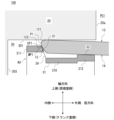
図1は、実施形態に係るオイルリング40を備える内燃機関100の部分断面図である。図1では、オイルリング40の軸方向に沿う断面が図示されている。なお、図1は、模式図であり、オイルリング40を簡略化して図示している。図1に示すように、内燃機関100では、シリンダ10の内壁面10aとシリンダ10に装着されたピストン20の外周面20aとの間に所定の離間距離が確保されることにより、ピストン隙間PC1が形成されている。また、ピストン20の外周面20aには、リング溝30が形成されている。リング溝30は、燃焼室側に形成された上壁301と、クランク室側に形成されて上壁301に対向する下壁302と、上壁301と下壁302の内周縁同士を接続する接続壁303とを有する。このリング溝30には、本実施形態に係るオイルリング40が装着されている。
[overall structure]
FIG. 1 is a partial cross-sectional view of an
オイルリング40は、ピストン20の往復運動に伴ってシリンダ10の内壁面10aを摺動する摺動部材である。オイルリング40は、いわゆる3ピース型の組合せオイルリングであり、図1に示すように、一対のセグメント1,2とスペーサエキスパンダ3とを備える。オイルリング40は、リング溝30に装着されることでピストン20に組み付けられる。
The
以下、図1に示すように、オイルリング40の中心軸に沿う方向(軸方向)を「上下方向」と定義する。また、オイルリング40の軸方向のうち、内燃機関100における燃焼室側(図1における上側)を「上側」と定義し、その反対側、即ち、クランク室側(図1における下側)を「下側」と定義する。また、以下のオイルリング40の説明において、特に指定しない限りは、「周長方向」とはオイルリング40の周長方向のことを指し、「径方向」とはオイルリング40の径方向のことを指し、「軸方向」とはオイルリング40の軸方向のことを指す。オイルリング40の周長方向、径方向、及び軸方向は、夫々、一対のセグメント1,2の周長方向、径方向、及び軸方向と一致する。また、本明細書では、図1に示すようにピストンリングが組付けられたピストンがシリンダに挿入された状態を「使用状態」と称する。また、本明細書において、「バレル形状」とは、頂部を含んで凸状となるように湾曲した面形状のことを指し、頂部がリングの軸方向幅における中央に位置し軸方向に対称な形状である「対称バレル形状」や頂部がリングの軸方向幅における中央から離れており軸方向に非対称な形状である「偏心バレル形状」を含むものとする。また、本明細書において、「テーパ形状」とは、クランク室側に向かうに従ってリングの中心軸から離れるように(つまり、拡径するように)傾斜した面形状又はクランク室側に向かうに従ってリングの中心軸に近づくように(つまり、縮径するように)傾斜した面形状のことを指す。
Hereinafter, as shown in FIG. 1, the direction along the central axis of the oil ring 40 (axial direction) is defined as the "up-down direction". In addition, in the axial direction of the
[セグメント]
一対のセグメント1,2は、オイルリング40の軸回りに環状に形成されており、互いに独立して軸方向に並んで設けられている。図1に示すように、一対のセグメント1,2
のうち上側セグメント1が上側(燃焼室側)に位置し、下側セグメント2が下側(クランク室側)に位置する。一対のセグメント1,2の材質としては、ステンレス鋼やばね鋼等が例示される。なお、上側セグメント1や下側セグメント2の内周面には、化成処理被膜や窒化処理被膜等が形成されていてもよい。
[segment]
The pair of
Of these, the
図1に示すように、上側セグメント1は、外周側に設けられた第1外周面11と、内周側に設けられた第1内周面12(本発明に係る上側セグメントの内周面に相当)と、燃焼室側に面する第1上面13と、クランク室側に面する第1下面14と、を含む。上側セグメント1の軸方向端面である第1上面13と第1下面14は互いに平行であり、第1上面13と第1下面14とによって、上側セグメント1の軸方向における幅が規定される。但し、第1上面13と第1下面14は平行でなくてもよい。図1に示すように、上側セグメント1は、第1上面13がリング溝30の上壁301に対向するように設けられ、第1外周面11を摺動面としてシリンダ10の内壁面10aを摺動する。
As shown in FIG. 1, the
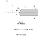
図2は、実施形態に係る上側セグメント1の第1内周面12の形状を説明するための断面図である。図2では、上側セグメント1の周長方向に直交する断面が図示されている。図2において、符号A1は上側セグメント1の中心軸を示す。また、符号CL1は、上側セグメント1の軸方向幅の中央を通る線を示す。また、符号MP1は、第1内周面12の軸方向における中央位置(軸方向幅の上下中央位置)を示す。
Figure 2 is a cross-sectional view for explaining the shape of the first inner
図2に示すように、第1内周面12は、内周頂部P1を含む。内周頂部P1は、オイルリング40の周長方向に直交する断面において、第1内周面12における他の部位よりも径方向内側に位置し、第1内周面12において最小径となる部位である。第1内周面12は、バレル形状を有する。即ち、第1内周面12は、周長方向に直交する断面において、内周頂部P1を含んで径方向内側に凸状となるように湾曲している。更に、内周頂部P1は、第1内周面12の軸方向幅の上下中央位置MP1よりも上側(燃焼室側)に位置しており、これにより、第1内周面12は、上下方向(軸方向)において非対称となっている。つまり、第1内周面12は、偏心バレル形状となっている。ここで、内周頂部P1よりも上側の領域を上側内周領域121とし、上側内周領域121よりも下側の領域を下側内周領域122とする。下側内周領域122は、内周頂部P1を含む。上側内周領域121は、内周頂部P1から上側に向かうに従って拡径するように湾曲しており、下側内周領域122は、内周頂部P1から下側に向かうに従って拡径するように湾曲している。つまり、第1内周面12は、軸方向において、内周頂部P1から離れるに従って拡径するように形成されている。
2, the first inner
図1に示すように、下側セグメント2は、外周側に設けられた第2外周面21と、内周側に設けられた第2内周面22と、燃焼室側に面する第2上面23と、クランク室側に面する第2下面24と、を含む。下側セグメント2の軸方向端面である第2上面23と第2下面24は互いに平行であり、第2上面23と第2下面24とによって、下側セグメント2の軸方向における幅が規定される。また、下側セグメント2は、第2下面24がリング溝30の下壁302に対向するように設けられ、第2外周面21を摺動面としてシリンダ10の内壁面10aを摺動する。下側セグメント2の第2内周面22は、対称バレル形状を有している。なお、下側セグメント2の形状は特に限定されない。
As shown in FIG. 1, the
[スペーサエキスパンダ]
スペーサエキスパンダ3は、図1に示すように一対のセグメント1,2の間に設けられており、使用状態において、一対のセグメント1,2を径方向外側へ(つまり、シリンダ10の内壁面10aへ)付勢する。
[Spacer expander]
The
図3は、実施形態に係るスペーサエキスパンダ3の一部の斜視図である。図3に示すよ
うに、スペーサエキスパンダ3は、軸方向に変位する波状をなす周期要素が周長方向に複数連なって構成されており、オイルリング40の径方向視(径方向の外側または内側から視認したとき)において周長方向に連続する波状に形成されている。具体的には、スペーサエキスパンダ3は、軸方向及び周長方向に離間して周長方向に交互に配置された複数の上片31及び下片32と、周長方向において隣り合う上片31と下片32と連結する連結片33と、を含む。複数の上片31は、周長方向に沿って間隔を空けて配列されている。複数の下片32は、オイルリング40がピストン20に組み付けられた際に(つまり、使用状態において)複数の上片31よりも下側に位置するように、設けられている。また、複数の下片32は、下片32の夫々が周長方向において上片31の夫々と交互に配置されるように配列されている。上片31及び下片32は、軸方向と直交するように設けられており、軸方向において互いに離間している。連結片33は、周長方向において隣り合う上片31と下片32の周長方向における端部同士を連結している。これにより、スペーサエキスパンダ3は、軸方向において波状に形成されている。
3 is a perspective view of a part of the
図4は、実施形態に係るオイルリング40の部分断面図である。図4では、オイルリング40の周長方向に直交する断面が図示されている。図4に示すように、上片31は、上側ベース部310と上側耳部311と上側支持部312とを含む。上側ベース部310は、軸方向と直交するように径方向に延びている。上側耳部311は、径方向における上側ベース部310の内側に起立形成されており、上側ベース部310に対して上側に突出している。また、上側耳部311は、使用状態において上側セグメント1よりも径方向内側に位置するように設けられており、上側セグメント1の第1内周面12に当接することで、上側セグメント1を径方向の外側へ押圧する。上側耳部311において第1内周面12に当接する押圧面S1は、オイルリング40の周長方向に直交する断面において、下側に向かうに従ってオイルリング40の中心軸から離れるように(つまり、拡径するように)傾斜している。上側支持部312は、径方向における上側ベース部310の外側に起立形成されており、上側ベース部310に対して上側に突出している。また、上側支持部312は、使用状態において上側セグメント1の第1下面14に当接することで、上側セグメント1を支持する。上側支持部312において第1内周面12に当接する支持面S2は、径方向に延びている。また、上側耳部311の根元にはオイルが通過可能な貫通孔34が形成されている。なお、貫通孔34は形成されていなくてもよい。また、本発明に係る上片は上側支持部312を有さなくてもよい。
Figure 4 is a partial cross-sectional view of the
図4に示すように、下片32は、下側ベース部320と下側耳部321と下側支持部322とを含む。下側ベース部320は、軸方向と直交するように径方向に延びている。下側耳部321は、径方向における下側ベース部320の内側に起立形成されており、下側ベース部320に対して下側に突出している。また、下側耳部321は、使用状態において下側セグメント2よりも径方向内側に位置するように設けられており、下側セグメント2の第2内周面22に当接することで、下側セグメント2を径方向の外側へ押圧する。下側耳部321において第2内周面22に当接する押圧面S3は、オイルリング40の周長方向に直交する断面において、下側に向かうに従ってオイルリング40の中心軸に近づくように(つまり、縮径するように)傾斜している。また、下側支持部322は、使用状態において下側セグメント2の第2上面23に当接することで下側セグメント2を支持する。下側支持部322において第2内周面22に当接する支持面S4は、径方向に延びている。また、下側耳部321の根元にも貫通孔34が形成されている。なお、貫通孔34は形成されていなくてもよい。また、本発明に係る下片は下側支持部322を有さなくてもよい。
As shown in FIG. 4, the
なお、本発明に係るスペーサエキスパンダの形状は、上述したものに限定されない。 The shape of the spacer expander according to the present invention is not limited to the above.
[オイルシールについて]
図5は、実施形態における上側セグメント1の接触状態を説明するための断面図である。図5では、ピストン20の上昇行程における上側セグメント1の状態が図示されている。図5の符号CP1は、第1内周面12における、スペーサエキスパンダ3の上側耳部311の押圧面S1との接触部分(以下、内周接触部CP1とする)を示す。図5に示すように、第1内周面12は、下側内周領域122においてスペーサエキスパンダ3の押圧面S1と接触する。このとき、内周頂部P1が第1内周面12の軸方向幅の上下中央位置MP1よりも上側に位置していることから、第1内周面12は、内周頂部P1が第1内周面12の軸方向幅の上下中央に位置する場合よりも上側の位置でスペーサエキスパンダ3の押圧面S1と接触する。つまり、第1内周面12が対称バレル形状の場合よりも内周接触部CP1の位置が上側にシフトする。そのため、上側セグメント1の第1上面13とリング溝30の上壁301との接触面圧が高められ、接触部分におけるシール性能が向上する。これにより、リング溝30内のオイルが上側セグメント1の第1上面13とリング溝30の上壁301との間を通って燃焼室へ流出することによるオイル上がりが抑制される。
[About oil seals]
5 is a cross-sectional view for explaining the contact state of the
[作用・効果]
以上のように、実施形態に係るオイルリング40は、周長方向に直交する断面において、上側セグメント1の第1内周面12の内周頂部P1が第1内周面12の軸方向幅の上下中央位置MP1よりも上側に位置するように、構成されている。つまり、第1内周面12が偏心形状となっている。これにより、上側セグメント1の第1上面13とリング溝30の上壁301との接触面圧を高め、オイル上がりを抑制することができる。その結果、実施形態によれば、オイルリング40のシール性能を向上させ、オイル消費を低減することができる。
[Action and Effects]
As described above, the
更に、上側セグメント1の第1内周面12は、周長方向に直交する断面において、内周頂部P1を含んで径方向内側へ凸状となるように湾曲したバレル形状を有する。そのため、第1内周面12は、バレル曲面でスペーサエキスパンダ3の押圧面S1と接触することとなる。但し、本発明における上側セグメントの内周面の形状はバレル形状に限定されない。また、内周頂部は平坦状であってもよい。
Furthermore, the first inner
また、図2に示すように、上側セグメント1の軸方向幅(軸方向における上側セグメント1の幅)をh1とする。第1上面13と第1下面14とが平行な場合、h1は、第1内周面12の軸方向幅と等しい。また、内周頂部P1と上下中央位置MP1との軸方向における距離(内周頂点ずれ)をd1とする。また、d1のh1に対する比率をαとする。第1内周面12は、内周偏心形状であるため、0<d1<h1/2、0<α<50%となる。このとき、αは、2.5%超えて50%未満であることが好ましく、5%以上50%未満であることが更に好ましい。αを上述の範囲とすることで、上側セグメント1の第1上面13とリング溝30の上壁301との接触面圧をより高め、オイルリング40のシール性能をより向上させることができる。但し、本発明におけるh1とd1との関係は上記に限定されない。なお、セグメントの製造上、内周頂部の上下位置の誤差により、αには2%程度のばらつきがある。
As shown in FIG. 2, the axial width of the upper segment 1 (the width of the
また、下側セグメント2の第2内周面22の形状は特に限定されないが、第2内周面22も偏心形状としてもよい。図6は、下側セグメント2の第2内周面22の形状の一例を説明するための断面図である。図6では、下側セグメント2の周長方向に直交する断面が図示されている。図6において、符号A2は下側セグメント2の中心軸を示す。また、符号CL2は、下側セグメント2の軸方向幅の中央を通る線を示す。また、符号MP2は、第2内周面22の軸方向における中央位置(軸方向幅の上下中央位置)を示す。図6に示すように、第2内周面22は、下側セグメント2の周長方向に直交する断面において、第2内周面22における他の部位よりも下側セグメントの径方向内側に位置すると共に第2内周面22において最小径となる内周頂部P2を含み、内周頂部P2が中央位置MP2よ
りも下側(クランク室側)に位置してもよい。これにより、下側セグメント2の第2下面24とリング溝30の下壁302との接触面圧をより高め、オイルリング40のシール性能を更に向上させることができる。
The shape of the second inner
[変形例]
以下、実施形態に係る上側セグメントの変形例について説明する。以下の説明では、上述の上側セグメント1との相違点を主に説明し、同様の構成については同一の符号を付すことで詳細な説明を割愛する。以下に説明する上側セグメント1A,1Bは、上側セグメント1に代えてオイルリング40を構成することができる。
[Modification]
Modified examples of the upper segment according to the embodiment will be described below. In the following description, differences from the above-described
[変形例1]
図7は、変形例1に係る上側セグメント1Aの周長方向に直交する断面図である。図7に示すように、上側セグメント1Aは、第1内周面12の上側内周領域121及び下側内周領域122がテーパ形状を有する点で上側セグメント1と相違する。具体的には、周長方向に直交する断面において、上側内周領域121が内周頂部P1から上側に向かうに従って上側セグメント1Aの中心軸A1から離れるように傾斜しており、下側内周領域122が内周頂部P1から下側に向かうに従って中心軸A1から離れるように傾斜している。なお、変形例1の内周頂部P1はR形状となっているが、内周頂部は平坦状であってもよい。
[Modification 1]
7 is a cross-sectional view perpendicular to the circumferential direction of the
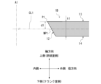
[変形例2]
図8は、変形例2に係る上側セグメント1Bの周長方向に直交する断面図である。図8に示すように、上側セグメント1Bは、第1内周面12が全体としてテーパ形状を有する点で上側セグメント1と相違する。第1内周面12は、周長方向に直交する断面において、内周頂部P1から下側に向かうに従って上側セグメント1Bの中心軸A1から離れるように傾斜している。上側セグメント1Bでは、d1はh1/2未満となり、αは50%未満となる。なお、変形例2の内周頂部P1もR形状となっているが、内周頂部は平坦状であってもよい。
[Modification 2]
Fig. 8 is a cross-sectional view perpendicular to the circumferential direction of the
[その他の変形例]
上述した上側セグメント1,1A,1Bの内周形状は、適宜組み合わせることができる。例えば、図2に示す上側セグメント1の第1内周面12において、上側内周領域121を傾斜面としてもよい。具体的には、上側内周領域121を、内周頂部P1から上側に向かうに従って上側セグメント1の中心軸A1から離れるように傾斜した傾斜面(テーパ面)とし、下側内周領域122を、内周頂部P1から下側に向かうに従って中心軸A1から離れるように湾曲した湾曲面(R面)としてもよい。また、図2に示す第1内周面12において、下側内周領域122を、内周頂部P1から下側に向かうに従って中心軸A1から離れるように傾斜した傾斜面としてもよい。
[Other Modifications]
The inner peripheral shapes of the
[シール性能評価]
実施形態に係る上側セグメントのシール性能を解析により評価した。解析では、内燃機関のピストンのリング溝にオイルリングを組み付けた状態を想定し、上側セグメントの上面とリング溝の上壁との接触面圧を導出した。解析は、以下の実施例1~5、及び比較例に係る上側セグメントを用いたオイルリングの夫々について実施した。
[Sealing performance evaluation]
The sealing performance of the upper segment according to the embodiment was evaluated by analysis. In the analysis, a state in which an oil ring is assembled in a ring groove of a piston of an internal combustion engine was assumed, and the contact surface pressure between the upper surface of the upper segment and the upper wall of the ring groove was derived. The analysis was performed for each of the oil rings using the upper segments according to the following Examples 1 to 5 and Comparative Example.
[実施例]
実施例1~5に係るオイルリングは、図2に示した上側セグメント1と同様のセグメントを用いた。実施例1は、d1=0.01mm、h1=0.4mm、α=2.5%である。実施例2は、d1=0.02mm、h1=0.4mm、α=5.0%である。実施例3は、d1=0.08mm、h1=0.4mm、α=20%である。実施例4は、d1=0
.185mm、h1=0.4mm、α=46.3%である。実施例5は、d1=0.08mm、h1=0.3mm、α=26.7%である。
[Example]
The oil rings according to Examples 1 to 5 used a segment similar to the
In Example 5, d1 = 0.08 mm, h1 = 0.3 mm, and α = 26.7%.
[比較例]
図9は、比較例に係る上側セグメント1Xの周長方向に直交する断面図である。図9に示すように、比較例に係る上側セグメント1Xの第1内周面12は、内周頂部P1が第1内周面12の軸方向幅の上下中央に位置する対称バレル形状を有している。比較例は、d1=0mm、h1=0.4mm、α=0%である。
[Comparative Example]
Fig. 9 is a cross-sectional view perpendicular to the circumferential direction of an
[解析結果]
表1に解析結果を示す。接触面圧は、上側セグメントの上面とオイル溝の上壁との接触部分の平均面圧を導出し、比較例に対する比率とした。

The analysis results are shown in Table 1. The contact pressure was calculated by calculating the average contact pressure of the contact portion between the top surface of the upper segment and the top wall of the oil groove, and expressed as a ratio to the comparative example.
表1に示すように、実施例1~5において、比較例よりも接触面圧が高いことが分かる。これにより、内周頂点を内周面軸方向幅の上下中央よりも上側に位置させることによるシール性能の向上を確認できた。また、αを5%以上とすることによって接触面圧が顕著に高まることを確認できた。 As shown in Table 1, it can be seen that the contact surface pressure is higher in Examples 1 to 5 than in the comparative example. This confirmed that the sealing performance is improved by positioning the inner circumferential apex above the vertical center of the axial width of the inner circumferential surface. It was also confirmed that the contact surface pressure is significantly increased by setting α to 5% or more.
<その他>
以上、本発明の好適な実施形態について説明したが、上述した種々の形態は、可能な限り組み合わせることができる。
<Other>
Although the preferred embodiments of the present invention have been described above, the above-mentioned various aspects can be combined to the extent possible.
100:内燃機関
10:シリンダ
20:ピストン
30:リング溝
40:オイルリング
1:上側セグメント
11:第1外周面
12:第1内周面(本発明に係る内周面の一例)
13:第1上面
14:第1下面
2:下側セグメント
3:スペーサエキスパンダ
311:上側耳部
P1:内周頂部
S1:押圧面
100: Internal combustion engine 10: Cylinder 20: Piston 30: Ring groove 40: Oil ring 1: Upper segment 11: First outer peripheral surface 12: First inner peripheral surface (an example of an inner peripheral surface according to the present invention)
13: First upper surface 14: First lower surface 2: Lower segment 3: Spacer expander 311: Upper ear portion P1: Inner circumferential apex portion S1: Pressing surface
Claims (5)
前記上側セグメントの軸方向端面である上面と下面は互いに平行であって、
前記上側セグメントの内周面は、前記上側セグメントの周長方向に直交する断面において、前記内周面における他の部位よりも前記上側セグメントの径方向内側に位置すると共に前記内周面において最小径となる内周頂部を含み、
前記内周頂部は、前記上側セグメントの周長方向に直交する断面において、前記上側セグメントの軸方向における前記内周面の中央位置よりも前記燃焼室側に位置し、
前記内周面は、前記上側セグメントの周長方向に直交する断面において、前記内周頂部から前記内燃機関のクランク室側に向かうに従って前記上側セグメントの中心軸から離れるように湾曲した下側内周領域を有し、前記下側内周領域において前記スペーサエキスパンダと接触するように構成されている、
上側セグメント。 An oil ring is fitted in a ring groove formed in a piston of an internal combustion engine, and among a pair of segments arranged side by side in the axial direction of the oil ring and biased radially outward by a spacer expander, an upper segment is provided on a combustion chamber side of the internal combustion engine,
The upper and lower surfaces, which are axial end surfaces of the upper segment, are parallel to each other,
an inner circumferential surface of the upper segment includes an inner circumferential apex portion that is located radially inward of the upper segment relative to other portions of the inner circumferential surface in a cross section perpendicular to a circumferential direction of the upper segment and that has a minimum diameter on the inner circumferential surface,
the inner peripheral apex is located closer to the combustion chamber than a center position of the inner peripheral surface in the axial direction of the upper segment in a cross section perpendicular to a circumferential direction of the upper segment,
the inner circumferential surface has a lower inner circumferential region that is curved in a cross section perpendicular to a circumferential direction of the upper segment so as to move away from a central axis of the upper segment from the inner circumferential apex toward a crank chamber of the internal combustion engine, and is configured to come into contact with the spacer expander at the lower inner circumferential region.
Upper segment.
請求項1に記載の上側セグメント。 the inner circumferential surface has a curved shape that is convex toward a radially inward direction of the upper segment, the curved shape including the inner circumferential apex, in a cross section perpendicular to a circumferential direction of the upper segment.
The upper segment of claim 1 .
請求項1又は2に記載の上側セグメント。 a distance in an axial direction of the upper segment between the inner circumferential apex and a center position of the inner circumferential surface is more than 2.5% and less than 50% of an axial width of the upper segment;
An upper segment according to claim 1 or 2.
請求項1から3の何れか一項に記載の上側セグメント。 a distance between the inner circumferential apex and a center position of the inner circumferential surface of the upper segment in the axial direction is equal to or greater than 5% and less than 50% of an axial width of the upper segment;
An upper segment according to any one of claims 1 to 3.
前記オイルリングの軸方向に並んで設けられる一対のセグメントと、前記一対のセグメ
ントを径方向の外側へ付勢するスペーサエキスパンダと、を備え、
前記一対のセグメントのうち前記内燃機関において燃焼室側に設けられる上側セグメントの軸方向端面である上面と下面は互いに平行であって、前記上側セグメントの内周面は、前記上側セグメントの周長方向に直交する断面において、前記内周面における他の部位よりも前記上側セグメントの径方向内側に位置すると共に前記内周面において最小径となる内周頂部を含み、
前記内周頂部は、前記上側セグメントの周長方向に直交する断面において、前記上側セグメントの軸方向における前記内周面の中央位置よりも前記燃焼室側に位置し、
前記内周面は、前記上側セグメントの周長方向に直交する断面において、前記内周頂部から前記内燃機関のクランク室側に向かうに従って前記上側セグメントの中心軸から離れるように湾曲した下側内周領域を有し、前記下側内周領域において前記スペーサエキスパンダと接触するように構成されている、
オイルリング。 An oil ring that is fitted to a ring groove formed in a piston of an internal combustion engine,
a pair of segments arranged side by side in an axial direction of the oil ring; and a spacer expander that biases the pair of segments radially outward,
an upper segment of the pair of segments that is provided on a combustion chamber side of the internal combustion engine has an upper surface and a lower surface that are axial end surfaces parallel to each other, and an inner circumferential surface of the upper segment includes an inner circumferential apex portion that is located radially inside the upper segment relative to other portions of the inner circumferential surface and has a minimum diameter on the inner circumferential surface in a cross section perpendicular to a circumferential direction of the upper segment,
the inner peripheral apex is located closer to the combustion chamber than a center position of the inner peripheral surface in the axial direction of the upper segment in a cross section perpendicular to a circumferential direction of the upper segment,
the inner circumferential surface has a lower inner circumferential region that is curved in a cross section perpendicular to a circumferential direction of the upper segment so as to move away from a central axis of the upper segment from the inner circumferential apex toward a crank chamber of the internal combustion engine, and is configured to come into contact with the spacer expander at the lower inner circumferential region.
Oil ring.
Priority Applications (1)
| Application Number | Priority Date | Filing Date | Title |
|---|---|---|---|
| JP2021161868A JP7529635B2 (en) | 2021-09-30 | 2021-09-30 | Upper segment and oil ring |
Applications Claiming Priority (1)
| Application Number | Priority Date | Filing Date | Title |
|---|---|---|---|
| JP2021161868A JP7529635B2 (en) | 2021-09-30 | 2021-09-30 | Upper segment and oil ring |
Publications (2)
| Publication Number | Publication Date |
|---|---|
| JP2023051293A JP2023051293A (en) | 2023-04-11 |
| JP7529635B2 true JP7529635B2 (en) | 2024-08-06 |
Family
ID=85805676
Family Applications (1)
| Application Number | Title | Priority Date | Filing Date |
|---|---|---|---|
| JP2021161868A Active JP7529635B2 (en) | 2021-09-30 | 2021-09-30 | Upper segment and oil ring |
Country Status (1)
| Country | Link |
|---|---|
| JP (1) | JP7529635B2 (en) |
Citations (2)
| Publication number | Priority date | Publication date | Assignee | Title |
|---|---|---|---|---|
| JP2003194222A (en) | 2001-12-28 | 2003-07-09 | Riken Corp | Side rail and combination oil ring |
| WO2020158949A1 (en) | 2019-02-01 | 2020-08-06 | 日本ピストンリング株式会社 | Multi-piece oil ring |
Family Cites Families (4)
| Publication number | Priority date | Publication date | Assignee | Title |
|---|---|---|---|---|
| US2815996A (en) * | 1955-02-14 | 1957-12-10 | Hastings Mfg Co | Piston ring assembly |
| US2965423A (en) * | 1960-06-15 | 1960-12-20 | Wilkening Mfg Co | Piston ring assembly |
| JPS5453108U (en) * | 1977-09-22 | 1979-04-12 | ||
| JPH04133064U (en) * | 1991-05-30 | 1992-12-10 | 株式会社リケン | Steel combination oil control ring |
-
2021
- 2021-09-30 JP JP2021161868A patent/JP7529635B2/en active Active
Patent Citations (3)
| Publication number | Priority date | Publication date | Assignee | Title |
|---|---|---|---|---|
| JP2003194222A (en) | 2001-12-28 | 2003-07-09 | Riken Corp | Side rail and combination oil ring |
| WO2020158949A1 (en) | 2019-02-01 | 2020-08-06 | 日本ピストンリング株式会社 | Multi-piece oil ring |
| CN113366212A (en) | 2019-02-01 | 2021-09-07 | 日本活塞环株式会社 | Combined oil ring |
Also Published As
| Publication number | Publication date |
|---|---|
| JP2023051293A (en) | 2023-04-11 |
Similar Documents
| Publication | Publication Date | Title |
|---|---|---|
| US7036823B2 (en) | Side rail and combined oil control ring incorporated with the side rails for reduction of oil consumption | |
| JP6533670B2 (en) | side rail | |
| US11320049B2 (en) | Piston ring combination | |
| US7243596B2 (en) | Spacer expander | |
| JP7254836B2 (en) | Combined oil ring | |
| US20150198112A1 (en) | Piston of internal combustion engine | |
| EP0676569A1 (en) | Low emission piston ring | |
| US6655697B2 (en) | Piston oil ring having land flanked by concave sidewalls | |
| US12222037B2 (en) | Piston ring arrangement, piston compressor and method for sealing a compression chamber | |
| JP7529635B2 (en) | Upper segment and oil ring | |
| US7429047B1 (en) | Piston ring assembly | |
| CN118679311B (en) | Piston ring | |
| US11713811B2 (en) | Multi-piece oil scraper ring with reduced friction | |
| KR20230044540A (en) | Piston ring combination and piston and piston ring combination structure | |
| US11162585B2 (en) | Piston having two piston rings | |
| JP7529709B2 (en) | Oil Ring | |
| JP3890750B2 (en) | Valve stem seal | |
| JP2010112324A (en) | Piston of internal combustion engine | |
| JP6780519B2 (en) | piston ring | |
| JP7578570B2 (en) | Spacer expander and oil ring | |
| JP7631508B2 (en) | Spacer expander and oil ring | |
| KR102429575B1 (en) | Piston | |
| JPH08303590A (en) | Seal structure | |
| WO2024202281A1 (en) | Oil ring | |
| EP4731920A1 (en) | Oil ring for a piston, and piston assembly |
Legal Events
| Date | Code | Title | Description |
|---|---|---|---|
| A621 | Written request for application examination |
Free format text: JAPANESE INTERMEDIATE CODE: A621 Effective date: 20221109 |
|
| A977 | Report on retrieval |
Free format text: JAPANESE INTERMEDIATE CODE: A971007 Effective date: 20230824 |
|
| A131 | Notification of reasons for refusal |
Free format text: JAPANESE INTERMEDIATE CODE: A131 Effective date: 20230905 |
|
| A521 | Request for written amendment filed |
Free format text: JAPANESE INTERMEDIATE CODE: A523 Effective date: 20231102 |
|
| A131 | Notification of reasons for refusal |
Free format text: JAPANESE INTERMEDIATE CODE: A131 Effective date: 20240130 |
|
| A521 | Request for written amendment filed |
Free format text: JAPANESE INTERMEDIATE CODE: A523 Effective date: 20240329 |
|
| TRDD | Decision of grant or rejection written | ||
| A01 | Written decision to grant a patent or to grant a registration (utility model) |
Free format text: JAPANESE INTERMEDIATE CODE: A01 Effective date: 20240625 |
|
| A61 | First payment of annual fees (during grant procedure) |
Free format text: JAPANESE INTERMEDIATE CODE: A61 Effective date: 20240725 |
|
| R150 | Certificate of patent or registration of utility model |
Ref document number: 7529635 Country of ref document: JP Free format text: JAPANESE INTERMEDIATE CODE: R150 |