JP7523822B2 - LOAD CONTROL SYSTEM, APPARATUS FOR CONTROLLING A LOAD ON A SUSPENSION CABLE, METHOD FOR AFFECTING AT LEAST ONE OF A POSITION, ORIENTATION, OR MOTION OF A LOAD CONTROL SYSTEM ON A SUSPENSION CABLE, AND COMPUTER READABLE MEDIUM - Patent application - Google Patents
LOAD CONTROL SYSTEM, APPARATUS FOR CONTROLLING A LOAD ON A SUSPENSION CABLE, METHOD FOR AFFECTING AT LEAST ONE OF A POSITION, ORIENTATION, OR MOTION OF A LOAD CONTROL SYSTEM ON A SUSPENSION CABLE, AND COMPUTER READABLE MEDIUM - Patent application Download PDFInfo
- Publication number
- JP7523822B2 JP7523822B2 JP2022530316A JP2022530316A JP7523822B2 JP 7523822 B2 JP7523822 B2 JP 7523822B2 JP 2022530316 A JP2022530316 A JP 2022530316A JP 2022530316 A JP2022530316 A JP 2022530316A JP 7523822 B2 JP7523822 B2 JP 7523822B2
- Authority
- JP
- Japan
- Prior art keywords
- fan
- motor
- thrust
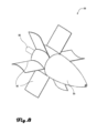
- unidirectional
- control system
- Prior art date
- Legal status (The legal status is an assumption and is not a legal conclusion. Google has not performed a legal analysis and makes no representation as to the accuracy of the status listed.)
- Active
Links
Images




Classifications
-
- B—PERFORMING OPERATIONS; TRANSPORTING
- B64—AIRCRAFT; AVIATION; COSMONAUTICS
- B64D—EQUIPMENT FOR FITTING IN OR TO AIRCRAFT; FLIGHT SUITS; PARACHUTES; ARRANGEMENT OR MOUNTING OF POWER PLANTS OR PROPULSION TRANSMISSIONS IN AIRCRAFT
- B64D35/00—Transmitting power from power plants to propellers or rotors; Arrangements of transmissions
- B64D35/04—Transmitting power from power plants to propellers or rotors; Arrangements of transmissions characterised by the transmission driving a plurality of propellers or rotors
-
- B—PERFORMING OPERATIONS; TRANSPORTING
- B63—SHIPS OR OTHER WATERBORNE VESSELS; RELATED EQUIPMENT
- B63H—MARINE PROPULSION OR STEERING
- B63H5/00—Arrangements on vessels of propulsion elements directly acting on water
- B63H5/07—Arrangements on vessels of propulsion elements directly acting on water of propellers
- B63H5/08—Arrangements on vessels of propulsion elements directly acting on water of propellers of more than one propeller
- B63H5/10—Arrangements on vessels of propulsion elements directly acting on water of propellers of more than one propeller of coaxial type, e.g. of counter-rotative type
-
- B—PERFORMING OPERATIONS; TRANSPORTING
- B64—AIRCRAFT; AVIATION; COSMONAUTICS
- B64C—AEROPLANES; HELICOPTERS
- B64C11/00—Propellers, e.g. of ducted type; Features common to propellers and rotors for rotorcraft
- B64C11/001—Shrouded propellers
-
- B—PERFORMING OPERATIONS; TRANSPORTING
- B64—AIRCRAFT; AVIATION; COSMONAUTICS
- B64D—EQUIPMENT FOR FITTING IN OR TO AIRCRAFT; FLIGHT SUITS; PARACHUTES; ARRANGEMENT OR MOUNTING OF POWER PLANTS OR PROPULSION TRANSMISSIONS IN AIRCRAFT
- B64D1/00—Dropping, ejecting, releasing or receiving articles, liquids, or the like, in flight
- B64D1/02—Dropping, ejecting, or releasing articles
- B64D1/08—Dropping, ejecting, or releasing articles the articles being load-carrying devices
- B64D1/10—Stowage arrangements for the devices in aircraft
-
- B—PERFORMING OPERATIONS; TRANSPORTING
- B64—AIRCRAFT; AVIATION; COSMONAUTICS
- B64D—EQUIPMENT FOR FITTING IN OR TO AIRCRAFT; FLIGHT SUITS; PARACHUTES; ARRANGEMENT OR MOUNTING OF POWER PLANTS OR PROPULSION TRANSMISSIONS IN AIRCRAFT
- B64D1/00—Dropping, ejecting, releasing or receiving articles, liquids, or the like, in flight
- B64D1/22—Taking-up articles from earth's surface
-
- B—PERFORMING OPERATIONS; TRANSPORTING
- B64—AIRCRAFT; AVIATION; COSMONAUTICS
- B64D—EQUIPMENT FOR FITTING IN OR TO AIRCRAFT; FLIGHT SUITS; PARACHUTES; ARRANGEMENT OR MOUNTING OF POWER PLANTS OR PROPULSION TRANSMISSIONS IN AIRCRAFT
- B64D27/00—Arrangement or mounting of power plants in aircraft; Aircraft characterised by the type or position of power plants
- B64D27/02—Aircraft characterised by the type or position of power plants
- B64D27/30—Aircraft characterised by electric power plants
-
- Y—GENERAL TAGGING OF NEW TECHNOLOGICAL DEVELOPMENTS; GENERAL TAGGING OF CROSS-SECTIONAL TECHNOLOGIES SPANNING OVER SEVERAL SECTIONS OF THE IPC; TECHNICAL SUBJECTS COVERED BY FORMER USPC CROSS-REFERENCE ART COLLECTIONS [XRACs] AND DIGESTS
- Y02—TECHNOLOGIES OR APPLICATIONS FOR MITIGATION OR ADAPTATION AGAINST CLIMATE CHANGE
- Y02T—CLIMATE CHANGE MITIGATION TECHNOLOGIES RELATED TO TRANSPORTATION
- Y02T50/00—Aeronautics or air transport
- Y02T50/60—Efficient propulsion technologies, e.g. for aircraft
Landscapes
- Engineering & Computer Science (AREA)
- Mechanical Engineering (AREA)
- Aviation & Aerospace Engineering (AREA)
- Chemical & Material Sciences (AREA)
- Combustion & Propulsion (AREA)
- Ocean & Marine Engineering (AREA)
- Structures Of Non-Positive Displacement Pumps (AREA)
- Transmission Devices (AREA)
- Control Of Positive-Displacement Air Blowers (AREA)
Description
関連出願へのクロスリファレンス
本出願は、2019年11月26日に出願され、「BIDIRECTIONAL FAN」と題する米国仮特許出願62/940,550の非仮出願であり、その一部継続であり、その利益を主張してこの参照により組み入れられる。また、本出願は、2020年8月7日に出願された「SUSPENDED LOAD STABILITY SYSTEMS AND METHODS」と題する米国特許出願16/988,373の一部継続出願であり、その利益を主張してこの参照により組み入れられる。本出願は、2019年1月15日に出願された特許協力条約特許出願番号PCT/US19/13603の継続出願であり、2018年2月8日に出願され、「SUSPENDED LOAD STABILITY SYSTEM THROUGH SELF POWERED AUTOMATED ELECTRIC DUCT FAN CONTROL」と題する米国仮特許出願62/627,920、並びに2018年11月8日に出願され、「LOAD STABILITY SYSTEM FOR SUSPENDED LOAD CHAOTIC MOTION」と題する米国仮特許出願62/757,414の利益を主張すると共に参照に組み入れられる。
CROSS-REFERENCE TO RELATED APPLICATIONS This application is a non-provisional, continuation-in-part of U.S. Provisional Patent Application No. 62/940,550, entitled "BIDIRECTIONAL FAN," filed November 26, 2019, the benefit of which is incorporated by reference herewith. This application is also a continuation-in-part of U.S. Patent Application No. 16/988,373, entitled "SUSPENDED LOAD STABILITY SYSTEMS AND METHODS," filed August 7, 2020, the benefit of which is incorporated by reference herewith. This application is a continuation of Patent Cooperation Treaty Patent Application No. PCT/US19/13603, filed January 15, 2019, and claims the benefit of and incorporates by reference U.S. Provisional Patent Application No. 62/627,920, filed February 8, 2018, and entitled "SUSPENDED LOAD STABILITY SYSTEM THROUGH SELF POWERED AUTOMATIC ELECTRIC DUCT FAN CONTROL," as well as U.S. Provisional Patent Application No. 62/757,414, filed November 8, 2018, and entitled "LOAD STABILITY SYSTEM FOR SUSPENDED LOAD CHAOTIC MOTION."
本開示は、2つのファンと1つのモータとを含むファンアセンブリのための、及びそれに関連する改良された装置(1つ又は複数)、システム(1つ又は複数)、及び方法(1つ又は複数)に向けられる;ファンは一方向であってよく、対向する方向に配置されてよく、ファンアセンブリは、例えば、キャリア下のサスペンションケーブル(吊りケーブル)に吊荷を制御するために使用されてもよい。 The present disclosure is directed to improved apparatus(es), system(s), and method(s) for and related to a fan assembly including two fans and a motor; the fans may be unidirectional or may be positioned in opposing directions, and the fan assembly may be used, for example, to control a load suspended on a suspension cable below a carrier.
翼型(エアホイル)は、例えば、翼、ブレード、フィン、又は帆の断面形状である。流体(例えば空気又は水)中を移動する翼形状の物体は、物体に対して、揚力、推力、又は抗力などの力を発生させることがある。以下では、例えばプロペラのように回転軸の周りに1つの構造で放射状に配列された翼形体を「ファン」と呼ぶことがある。 An airfoil is, for example, the cross-sectional shape of a wing, blade, fin, or sail. An airfoil-shaped object moving through a fluid (e.g., air or water) may generate forces such as lift, thrust, or drag on the object. In the following, an airfoil-shaped object that is radially arranged in one structure around a rotation axis, such as a propeller, may be referred to as a "fan."
ファンは、その回転軸を中心に2つの方向、例えば、時計回りと反時計回りに回転してもよい。ファンは、どちらの方向にも回転し、どちらの方向にも等しい推力が生じるように設計されてもよい。例えば、対称翼を有するファンは、どちらの方向に回転したときにも等しい推力を生じさせることができる。このようなファンを本明細書では「双方向ファン」と呼ぶことがある。双方向ファンと比較して、代替的に、ファンは、一方向に回転したときに大きな推力、大きな揚力、低減された抗力、又は騒音を提供するように設計されている場合がある。このようなファンを本明細書では「一方向ファン」と呼ぶ。一方向ファン(単方向ファン)は、非対称な翼を有するブレードを有することができる。 A fan may rotate in two directions about its axis of rotation, e.g., clockwise and counterclockwise. A fan may be designed to rotate in either direction and produce equal thrust in either direction. For example, a fan with symmetrical blades may produce equal thrust when rotating in either direction. Such a fan may be referred to herein as a "bidirectional fan." In comparison to a bidirectional fan, alternatively, a fan may be designed to provide greater thrust, greater lift, reduced drag, or noise when rotating in one direction. Such a fan may be referred to herein as a "unidirectional fan." A unidirectional fan may have blades with asymmetrical blades.
一方向ファンは、モータからの仕事をストラスト流体(推力流体)の加速に変換する際に、双方向ファンよりも効率的であると広く理解されており、ストラスト流体の加速は、揚力又は推力を提供するか、あるいは仕事を実行するものである。揚力又は推力が方向を有する場合、それは推力ベクトルと呼ばれることがある。 Unidirectional fans are widely understood to be more efficient than bidirectional fans at converting work from a motor into acceleration of the thrust fluid, which provides lift or thrust or performs work. When lift or thrust has a direction, it is sometimes called a thrust vector.
システムが異なる推力ベクトルを出力することが望ましい状況がある;望ましい推力ベクトルは、180度離れているなど、反対である場合がある。例えば、多くのボートのプロペラは、(ボートの船首に対して)前方推力ベクトルを提供するために第1の方向に、又は逆推力ベクトルを提供するために第2の方向に操作される場合がある。 There are situations in which it is desirable for a system to output different thrust vectors; the desired thrust vectors may be opposite, such as 180 degrees apart. For example, the propellers on many boats may be steered in a first direction to provide a forward thrust vector (relative to the bow of the boat), or in a second direction to provide a reverse thrust vector.
しかしながら、また、指摘したように、プロペラ/ファンが一方向である場合、プロペラの動作は、方向のうちの1つにおいて効率が悪くなる;プロペラが双方向である場合、それは両方の方向において等しく効率が良くなるが、プロペラが一方向で主に動作する場合、それは一方向のプロペラよりも全体的に効率が悪くなるであろう。 However, as also pointed out, if the propeller/fan is unidirectional, the propeller's operation will be less efficient in one of the directions; if the propeller is bidirectional, it will be equally efficient in both directions, but if the propeller operates predominantly in one direction, it will be less efficient overall than a unidirectional propeller.
このような状況で単一の双方向ファンを使用することの代替案は、2つの別個のモータによって駆動される2つの一方向ファンを使用することである。しかし、2つのモータは、システムの重量及び複雑さを増加させる可能性があり、そのいずれか又は両方が、システム全体の効率に悪影響を及ぼす可能性がある。 An alternative to using a single bidirectional fan in this situation is to use two unidirectional fans driven by two separate motors. However, two motors can increase the weight and complexity of the system, either or both of which can adversely affect the overall system efficiency.
反対の推力ベクトルを出力するシステム又は装置が望ましい状況は、人及び/又は装置(「荷」)が、ホイストシステムを使用して、ヘリコプター、飛行機、又はクレーンからケーブルで吊られた荷としてある場所に又はある場所から搬送されるときに発生する。クレーン、ヘリコプター、固定翼機、及びホイストシステムで荷を運ぶことができる他の構造物を、本明細書では「キャリア」と呼ぶことがある。このような操作の間、荷は、荷を不安定な、望ましくない、又は危険な状態で動かす原因となり得る風及び他の外部及び内部要因にさらされる。このような操作の間、荷をキャリアの下方の最低エネルギーの吊り位置以外の場所に移動させることが望ましい場合がある。そのような操作の間、1つ以上の推力ベクトル源から可変推力を出力するシステムを使用することが望ましい場合があり、ここで、推力ベクトル源は、互いに固定の幾何学的関係を有する場合がある。このような操作において、複数の推力ベクトル源は、「ベクトル推力制御」の原理で動作して、互いに対向することができる。 A situation in which a system or device that outputs opposing thrust vectors is desirable occurs when people and/or equipment ("loads") are transported to or from a location as cable-suspended loads from helicopters, airplanes, or cranes using a hoisting system. Cranes, helicopters, fixed-wing aircraft, and other structures that may carry loads with a hoisting system may be referred to herein as "carriers." During such operations, the loads are exposed to wind and other external and internal factors that may cause the loads to move in an unstable, undesirable, or dangerous manner. During such operations, it may be desirable to move the load to a location other than the lowest energy suspension position below the carrier. During such operations, it may be desirable to use a system that outputs variable thrust from one or more thrust vector sources, where the thrust vector sources may have a fixed geometric relationship to one another. In such operations, multiple thrust vector sources may oppose one another, operating under the principles of "vector thrust control."
ホイスト、スリング、及び他のキャリア操作において、吊られた荷の観察される運動は、以下の成分を含む:Y軸に沿った垂直(鉛直)方向の並進(上下の運動)(本明細書では「垂直方向の並進」と呼ぶ)、X軸及びZ軸のいずれか又は両方に沿った水平方向の並進、及びY軸の周りの回転すなわち「ヨー」である。ロール(X軸を中心とした回転)及びピッチ(Y軸を中心とした回転)も発生する可能性があるが、浮力がない状態でケーブルによって荷が吊り下げられている場合、典型的な運動は垂直移動、水平移動、及びヨーになる。垂直及び水平方向の移動は、キャリアの移動、サスペンション(吊り)ケーブルの引き込み・払い出し、荷の移動、荷とキャリアの運動量の違いや、風(プロップウォッシュ(propeller wash)を含む)、外力などによるサスペンション(吊り)ケーブルの移動で発生することがある。水平方向の移動は、横方向の動きとして、又はケーブルがキャリアに固定されている場所を振り子の枢軸点とする、荷の円錐形の振れ運動(「振り子運動」)として現れることがある;振り子運動は、荷が前後に加えて上下に揺れるので、一般に、垂直(鉛直)方向の移動の成分も含む。 In hoists, slings, and other carrier operations, the observed motion of a suspended load includes the following components: vertical (plumb) translation (up and down motion) along the Y axis (referred to herein as "vertical translation"), horizontal translation along either or both of the X and Z axes, and rotation or "yaw" about the Y axis. When a load is suspended by a cable in the absence of buoyancy, the typical motions are vertical, horizontal, and yaw, although roll (rotation about the X axis) and pitch (rotation about the Y axis) can also occur. Vertical and horizontal motions can occur due to carrier movement, retraction and retraction of the suspension cable, load movement, momentum differences between the load and carrier, movement of the suspension cable due to wind (including propeller wash), external forces, etc. Horizontal movement can appear as side-to-side motion, or as a conical swinging motion of the load ("pendulum motion"), with the pendulum pivoting where the cable is attached to the carrier; pendulum motion generally also includes a component of vertical movement, as the load swings up and down in addition to back and forth.
ヨー、横方向の動き、及び振り子運動は、リフト作業を複雑にし、遅れを生じさせ、航空機乗務員、クレーンオペレータ、及び地上の人々の死亡又は負傷につながる可能性がある。ヨーは人間にめまいや方向感覚の喪失をもたらすことがある。また、ヨーや横揺れや振り子運動は、荷の搬入や搬出にも支障をきたすことがある。例えば、船の甲板への荷の搬入は、甲板が安定しており、ヒーブ、ロール、又はピッチも受けない場合であっても、荷の振り子運動又はヨーによって著しく複雑になる可能性がある。
例えば、担架に乗せた人をヘリコプターに運び込んだり、ヘリコプターのストラットに乗せたりすることは、担架がヘリコプターに引き寄せられる際にヨーや振り子運動を受けると危険な場合がある。荷の望ましくない運動の1つ以上の成分は、荷がキャリアに引き寄せられ、サスペンションケーブルが短くなるにつれて、加速されるか、より顕著になる可能性がある。また、荷の水平運動及び振り子運動は、キャリアと相互作用して、キャリアに危険な又は望ましくない反応又は同調運動を生じさせる可能性がある。
Yaw, sideways and pendulum motion can complicate and delay lifting operations and can lead to death or injury to aircrew, crane operators and people on the ground. Yaw can cause dizziness and disorientation in humans. Yaw, sideways and pendulum motion can also interfere with the delivery and unloading of loads. For example, the delivery of a load to a ship's deck can be significantly complicated by the pendulum or yaw of the load, even if the deck is stable and not subject to heave, roll or pitch.
For example, carrying a person on a stretcher into a helicopter or onto the struts of the helicopter can be dangerous if the stretcher is subject to yaw and pendulum motion as it is pulled toward the helicopter. One or more components of the undesirable motion of the load can be accelerated or become more pronounced as the load is pulled toward the carrier and the suspension cables shorten. Also, the horizontal and pendulum motion of the load can interact with the carrier to cause dangerous or undesirable reactions or synchronous motions in the carrier.
さらに、いくつかの吊荷作業には、地表、崖壁、建物、橋、木の枝、張り出し、狭い通路などの障害物や、キャリア、荷、及び/又はサスペンションケーブルの1つ以上と干渉する可能性のある他の障害物がある場合がある。そのような障害物に対して、又は他の理由から、荷をキャリアより下の最低エネルギー位置で吊り下げない方法で、移動させることが望ましい場合がある。 Additionally, some lifting operations may involve obstacles such as the ground, cliff walls, buildings, bridges, tree branches, overhangs, narrow passages, or other obstacles that may interfere with the carrier, the load, and/or one or more of the suspension cables. It may be desirable to move the load over such obstacles, or for other reasons, in a manner that does not result in the load being suspended below the carrier in a minimum energy position.
ドローン又は海洋船舶を利用するものなどの他の操作も、動きを制御するためにファン及びモータを利用することができる。ドローンは、典型的には、揚力のためにその上方に位置するプロペラを有し、狭い空間において横方向に操縦することによっても利益を得ることができる。船舶は、船首スラスタや船尾スラスタなどの横型推進装置を用いて、船首や船尾を主推進スラスタとは異なる方向に向けることが多い。これらの装置は、しばしばトンネルスラスタと呼ばれ、小型の可逆性電気モータによって駆動される1つ又は複数のプロペラを有して、いずれかの方向に推力を提供することができる。しかし、これらの装置は、各方向のためのモータ及びファンを有するか、又は単一のモータ及び単一の双方向ファンを使用することができる。追加のモータの使用は、追加のシステム重量をもたらす可能性があり、双方向ファンの使用は、効率が悪くなる可能性がある。 Other operations, such as those utilizing drones or marine vessels, can also utilize fans and motors to control movement. Drones typically have propellers located above them for lift and can also benefit from maneuvering laterally in tight spaces. Vessels often use lateral propulsion devices, such as bow and stern thrusters, to point the bow or stern in a different direction than the main propulsion thrusters. These devices, often called tunnel thrusters, can have one or more propellers driven by small reversible electric motors to provide thrust in either direction. However, these devices can have a motor and fan for each direction or use a single motor and a single bidirectional fan. The use of additional motors can result in additional system weight and the use of bidirectional fans can be less efficient.
操縦が必要なシステムの性能は、システムのファンが出力できる推力ベクトルの大きさ、推力ベクトルが方向を切り替えることができる速度、及び希少で高価なバッテリー電力をそのような推力ベクトルに変換するシステムの効率によって制限される場合がある。これらの要因から、それぞれが独自のモーターを持つ一方向のファンを使用するインセンティブが生まれる。しかしながら、複数のモータは、重量及びシステムの複雑さを増加させる可能性がある。 The performance of a maneuvering system may be limited by the magnitude of the thrust vector that the system's fans can output, the speed at which the thrust vector can change direction, and the efficiency of the system in converting scarce and expensive battery power into such a thrust vector. These factors create an incentive to use unidirectional fans, each with its own motor. However, multiple motors can increase the weight and complexity of the system.
従って、利用可能な電力で最大の力ベクトルを依然として出力しながら、操縦装置の電力消費、サイズ、及び重量を低減する必要性が存在する。 Therefore, there is a need to reduce the power consumption, size, and weight of piloting devices while still outputting the maximum force vector with the available power.
1つの双方向ファンと1つのモータは、それぞれが独自のモータを有する2つの一方向ファンと比較すると、効率は落ちるが、対向する推力ベクトルに沿って双方向スラストを提供するために使用され得る。しかしながら、2つの一方向ファンに動力を供給するための2つのモータの使用は、単一の双方向ファン及び単一のモータと比較して、重量、システムの複雑さ、及びより多くの物理的スペースを増加させる。 A bidirectional fan and a motor can be used to provide bidirectional thrust along opposing thrust vectors, although with less efficiency compared to two unidirectional fans, each with its own motor. However, the use of two motors to power two unidirectional fans increases weight, system complexity, and more physical space compared to a single bidirectional fan and a single motor.
本開示は、これらの問題に対処し、各ファンのためのモータを必要とする代わりに、いずれかの回転方向で2つの一方向ファンを駆動するために単一のモータを使用してデバイス操縦の成功に必要な推力を提供し得る双方向スラストアセンブリ(双方向推力アセンブリ)に関するものである。このように、開示されたアセンブリは、よりコンパクトなソリューションを提供し、例えば、1つのモータと1つの双方向ファン又は2つのモータと2つの一方向ファンからなるシステムよりも少ない電力を消費し、従って、ここに開示された双方向スラストアセンブリを組み込む操縦システムの電池寿命を延長させることができる。 The present disclosure relates to a bidirectional thrust assembly that addresses these problems and can provide the thrust required for successful device maneuvering using a single motor to drive two unidirectional fans in either direction of rotation, instead of requiring a motor for each fan. In this manner, the disclosed assembly provides a more compact solution and consumes less power than, for example, a system consisting of one motor and one bidirectional fan or two motors and two unidirectional fans, thus extending the battery life of a maneuvering system incorporating the bidirectional thrust assembly disclosed herein.
本明細書に開示されるような双方向スラストアセンブリから利益を得ることができる状況の一例は、吊荷制御システムである。吊荷制御システム又は荷安定システム(共に「SLCS」と称す)は、荷の位置又はその付近で電気ダクトファンに見られるようなスラスタ、ファン、又はプロペラから力ベクトルを出力することによって、キャリアから独立して、荷を制御し得る。スラスタ、ファン、プロペラ、及び電動ダクト式ファンは、本明細書では「EDF」と呼ばれ、又は「ファン」と呼ばれることがある。SLCSのEFSは、対向する一対のファンで構成されてもよい。EDFによって生成される力ベクトルは、ヨー及び振り子運動を打ち消すために使用されてもよく、障害物を回避するため、又は通常の最低エネルギー吊り下げ位置に対してオフセット位置に荷を移動させるためなど、荷を水平に並進させるために使用されてもよく、それ以外に、キャリアから独立して、荷の細かい位置及びヨーを制御するために使用されてもよい。その結果、SLCSは、キャリア(運搬装置)の動きとは別に、荷の細かい位置とヨーを動的に制御するため、ミッションの安全性を高め、キャリアと荷の操作の性能を向上させることができる。 One example of a situation that may benefit from a bidirectional thrust assembly as disclosed herein is a load control system. A load control system or load stability system (collectively "SLCS") may control a load independently of the carrier by outputting force vectors from thrusters, fans, or propellers, such as those found in electric ducted fans, at or near the load. Thrusters, fans, propellers, and electric ducted fans are sometimes referred to herein as "EDFs" or "fans." The EFS of the SLCS may consist of a pair of opposed fans. The force vectors generated by the EDFs may be used to counter yaw and pendulum motion, to translate the load horizontally, such as to avoid obstacles or to move the load to an offset position relative to the normal lowest energy suspension position, or otherwise to control the fine position and yaw of the load independently of the carrier. As a result, the SLCS dynamically controls the precise position and yaw of the payload independent of the carrier's motion, enhancing mission safety and improving the performance of the carrier and payload operations.
SLCSは大量の電力を消費するため、SLCSの電力はバッテリパックによって提供されることがある。バッテリパックの電力が限られていると、SLCSの任務(ミッション)と操作の有効性が制限される可能性がある。さらに、SLCSは、力ベクトルの急激な変化から恩恵を受けるか、又は、力ベクトルの急激な変化を必要とする場合がある。また、SLCSは、力ベクトルの生成の高い効率から恩恵を受けるか、又はそれを必要とする場合がある。さらに、SLCSと荷を運搬するキャリアは、限られた吊り上げ能力を持つ可能性があるため、 SLCSは、軽量化から恩恵を受けるか、又は軽量化を必要とする場合もある。 Because the SLCS consumes a large amount of power, power for the SLCS may be provided by a battery pack. Limited battery pack power may limit the effectiveness of the SLCS's mission and operations. Additionally, the SLCS may benefit from or require rapid changes in the force vector. Also, the SLCS may benefit from or require high efficiency in the generation of the force vector. Additionally, the SLCS and the carrier carrying the load may have limited lifting capacity, so the SLCS may benefit from or require light weight.
垂直離着陸機(VTOL)や軽量航空機(”lighterthan-air aircraft”:空気より軽い航空機)も、移動中に横方向に操縦するため、又は離着陸中に安定化するために、反対方向の推力ベクトルを出力することができるスラスタから利益を得ることができる。VTOL構成は、固定翼機、ヘリコプター、ロケット、シクロコプター、ティルトローターなど、ドローンから乗客及び貨物機までの乗り物に見られることがある。軽量航空機には、飛行船、熱気球、及び類似の乗り物が含まれることがある。これらの機体は、横方向の推力を提供するためにファン及びモータを使用することができ、また、反対方向の推力ベクトルを出力することができるスラスタシステムから利益を得ることができる。 Vertical take-off and landing (VTOL) or lighter-than-air aircraft ("lighter-than-air aircraft") can also benefit from thrusters that can provide opposing thrust vectors to steer laterally while moving or to stabilize during take-off and landing. VTOL configurations can be found in vehicles ranging from drones to passenger and cargo aircraft, such as fixed-wing aircraft, helicopters, rockets, cyclocopters, and tiltrotors. Light aircraft can include airships, hot air balloons, and similar vehicles. These vehicles can use fans and motors to provide lateral thrust and can benefit from thruster systems that can provide opposing thrust vectors.
下向きの推力又は浮力は、VTOLや軽量航空機の機体を地面から持ち上げる揚力を提供するが、追加のスラスタは、所望のコースに沿って機体を方向付けるために、又は機体のヨーを引き起こすためのトルクを提供するために、横方向の力を提供することが必要となる場合がある。ファン及びモータの構成は、この操縦及び原動力を付与するために使用され得るが、複数の一方向モータに電力を供給する複数のモータの使用は、重量、システムの複雑さを増し、当該航空機にスペースを必要とする。そのような航空機は、本明細書に開示された軽量、小フットプリント、低電力の双方向スラスタシステムによって付与された、強化された敏捷性からの利益を得ることができる。 Downward thrust or buoyancy provides the lift that lifts a VTOL or light aircraft vehicle off the ground, but additional thrusters may be required to provide lateral forces to direct the vehicle along a desired course or to provide torque to induce yaw on the vehicle. Fan and motor configurations may be used to provide this steering and motive power, but the use of multiple motors to power multiple unidirectional motors adds weight, system complexity, and space requirements to the aircraft. Such aircraft may benefit from the enhanced agility imparted by the lightweight, small footprint, low power bidirectional thruster system disclosed herein.
開示されたシステム及び方法は、操縦される物体の少なくとも一部を必要とするあらゆる操作において使用され得る。例示的な操作は、ホイスト操作、ドローン配送システム、及び海洋船舶のトンネルスラスタを含むことができるが、これらに限定されるものではない。従って、システムが動作する媒体は、空気又は水などの任意の流体であってよいが、これに限定されるものではなく、流体は、「スラスト流体」と呼ばれてもよい。例えば、流体入口へのいかなる言及も、空気入口に置き換えてもよいし、その逆でもよい。以下の実施例におけるシステム及び方法は、当業者によって、過度の実験や負担なしに他の用途に適合させることができる。 The disclosed systems and methods may be used in any operation requiring at least a portion of an object to be steered. Exemplary operations may include, but are not limited to, hoisting operations, drone delivery systems, and tunnel thrusters on marine vessels. Thus, the medium in which the system operates may be any fluid, such as, but not limited to, air or water, and the fluid may be referred to as a "thrust fluid." For example, any reference to a fluid inlet may be replaced with an air inlet, or vice versa. The systems and methods in the following examples may be adapted for other applications by those of skill in the art without undue experimentation or burden.
双方向スラストアセンブリは、モータと、選択的動力伝達機構と、複数の一方向ファンとを含んでいてもよい。 The bidirectional thrust assembly may include a motor, a selective power transmission mechanism, and multiple unidirectional fans.
モータは、両端ドライブシャフト(ダブルエンドドライブシャフト)を含んでいてもよく、モータは、両端ドライブシャフトを時計回り方向又は反時計回り方向のいずれかに回転させるように構成されていてもよい。 The motor may include a double-ended drive shaft, and the motor may be configured to rotate the double-ended drive shaft in either a clockwise or counterclockwise direction.
選択的動力伝達機構は、例えば、複数のフリーホイールアセンブリ、複数のクラッチアセンブリ、及び又は双方向ドライブトレインを含んでいてもよい。複数のフリーホイールアセンブリは、それぞれ、爪車とラチェットホイール(ラチェット車)とを含んでいてもよい。爪車は、爪と、爪をラチェットホイールに係合させる爪係合機構と、を含んでもよい。ラチェットホイールは、ラチェットホイールのハブの内径に沿った歯を含み、歯は、爪が歯と一方向にのみ係合できるように構成されてもよい。選択的動力伝達機構は、両端ドライブシャフトの第1の端部と第1のファンとの間の第1のフリーホイールアセンブリと、両端ドライブシャフトの第2の端部と第2のファンとの間の第2のフリーホイールアセンブリとを含んでいてもよい。第1のフリーホイールアセンブリは、モータが第1の方向(例えば時計回り)に駆動されるときに、トルクなどの動力をモータから第1のファンに伝達するように構成されてもよく、第2のフリーホイールアセンブリは、モータが第2の方向(例えば反時計回り)に駆動されるときに、トルクをモータから第2のファンに伝達するように構成されてもよい。このように、選択的動力伝達機構は、モータの回転方向に基づいて、第1のファン又は第2のファンのいずれかに選択的に動力を供給してもよい。 The selective power transmission mechanism may include, for example, a plurality of freewheel assemblies, a plurality of clutch assemblies, and/or a bidirectional drive train. The plurality of freewheel assemblies may each include a ratchet wheel and a ratchet wheel. The ratchet wheel may include a pawl and a pawl engagement mechanism that engages the pawl with the ratchet wheel. The ratchet wheel may include teeth along an inner diameter of the hub of the ratchet wheel, and the teeth may be configured such that the pawl can only engage with the teeth in one direction. The selective power transmission mechanism may include a first freewheel assembly between a first end of the drive shaft at both ends and the first fan, and a second freewheel assembly between a second end of the drive shaft at both ends and the second fan. The first freewheel assembly may be configured to transfer power, such as torque, from the motor to the first fan when the motor is driven in a first direction (e.g., clockwise), and the second freewheel assembly may be configured to transfer torque from the motor to the second fan when the motor is driven in a second direction (e.g., counterclockwise). In this manner, the selective power transfer mechanism may selectively power either the first fan or the second fan based on the direction of rotation of the motor.
双方向スラストアセンブリのステータは、ファンの下流に存在してもよい。ステータは、ファンによって生成された推力を方向付けるか又は増強するように構成された複数の固定フィンを含んでいてもよい。 The stator of the bidirectional thrust assembly may be downstream of the fan. The stator may include a number of fixed fins configured to direct or augment the thrust generated by the fan.
双方向スラストアセンブリのケース又はそれを含むケースは、ストラスト流体入口と2つの出力ポートを含んでもよい。双方向スラストアセンブリのモータ、選択的動力伝達機構、及びファンは、ケース内にあってもよい。各ファンは、出力ポートに近接して、又は出力ポート内に配置されてもよい。 The case of the bidirectional thrust assembly or a case containing it may include a thrust fluid inlet and two output ports. The motor, selective power transmission mechanism, and fan of the bidirectional thrust assembly may be within the case. Each fan may be located adjacent to or within the output port.
実施形態では、各ケースは、双方向スラストアセンブリの中心部分又はその近くに配置されたメッシュ状又はスクリーン状のスラスト流体入口を含んでいてもよい。中央のメッシュ状スラスト流体入口構成が、例として図に示されているが、スラスト流体がファンに流れることを可能にする任意の開口部が使用されてもよい。 In an embodiment, each case may include a mesh or screen thrust fluid inlet located at or near a central portion of the bidirectional thrust assembly. A central mesh thrust fluid inlet configuration is shown in the figures by way of example, but any opening that allows thrust fluid to flow to the fan may be used.
双方向スラストアセンブリは、コントローラによって制御されてもよい。実施形態では、回路、モジュール、ソフトウェアで具現化されたアルゴリズム、又は他のシステム(「推力制御モジュール(スラスト制御モジュール)」)は、双方向スラストアセンブリを制御して、双方向スラストアセンブリが出力する推力の方向(例えば、出力推力ベクトルを制御するために)及び双方向スラストアセンブリのファンによって出力する推力ベクトルの大きさを制御してもよい。1つ以上の双方向スラストアセンブリは、推力制御モジュールによって、横方向の力又はトルクを出力し、それによって、荷を安定させる、荷の経路を制御する、航空機を操縦する、などのように、荷を制御するために使用されてもよい。SLCSに組み込まれる双方向スラストアセンブリの例は、図16、図17、及び図18に関連して図示され、詳述される。推力制御モジュールに入力を提供するために使用され得るリモートペンダントの例は、図12に関連して図示され、詳述されている。推力制御モジュール及び又はリモートペンダントを実装するための論理的構成要素の例を、図13に図示して説明する。推力制御モジュールの例は、図14及び図15に関連して図示され、詳述されている。 The bidirectional thrust assemblies may be controlled by a controller. In an embodiment, a circuit, module, software-embodied algorithm, or other system ("thrust control module") may control the bidirectional thrust assemblies to control the direction of thrust output by the bidirectional thrust assemblies (e.g., to control the output thrust vector) and the magnitude of the thrust vector output by the fan of the bidirectional thrust assemblies. One or more bidirectional thrust assemblies may be used by the thrust control module to output lateral forces or torques, thereby controlling a load, such as stabilizing the load, controlling the path of the load, steering the aircraft, etc. Examples of bidirectional thrust assemblies incorporated into the SLCS are illustrated and described in detail in connection with FIGS. 16, 17, and 18. An example of a remote pendant that may be used to provide inputs to the thrust control module is illustrated and described in detail in connection with FIG. 12. Example logical components for implementing the thrust control module and/or the remote pendant are illustrated and described in FIG. 13. An example of a thrust control module is shown and described in detail in connection with Figures 14 and 15.
両端ドライブシャフトの両端にファンを有する両端ドライブシャフトを有するモータを含む実施形態では、モータは、いずれかの方向に回転させられてもよく、選択的動力伝達機構は、モータの回転方向に応じてファンが推力ベクトルを生成するようにしてもよい。 In embodiments including a motor with a double-ended drive shaft with fans on both ends of the drive shaft, the motor may be rotated in either direction and the selective power transfer mechanism may cause the fan to generate a thrust vector depending on the direction of rotation of the motor.
実施形態では、双方向推力アセンブリは、第2のファンがモータから動力を受け取るときなど、第1のファンが回転するのを防止するためのブレーキを含んでいてもよい。実施形態において、ブレーキは、図9及び図10に関連して詳述されるように、磁石からなる摩擦のないブレーキであってもよい。ブレーキは、双方向スラストアセンブリが推力ベクトルをより迅速に変更することを可能にし、双方向スラストアセンブリがより効率的に動作することを可能にし、双方向スラストアセンブリを通るスラスト流体の流れを安定させてもよい。 In an embodiment, the bidirectional thrust assembly may include a brake to prevent the first fan from rotating, such as when the second fan receives power from the motor. In an embodiment, the brake may be a frictionless brake made of magnets, as detailed in connection with FIGS. 9 and 10. The brake may allow the bidirectional thrust assembly to change thrust vectors more quickly, allowing the bidirectional thrust assembly to operate more efficiently, and may stabilize the flow of thrust fluid through the bidirectional thrust assembly.
図1は、実施形態に従った双方向スラストアセンブリ100を図示している。双方向スラストアセンブリ100のいくつかの構成要素又はすべての構成要素は、ケース102内に収容されてもよい。ケース102は、流体入口104及び2つのインライン出力ポート106(直列出力ポート)を含むことができる。
FIG. 1 illustrates a
流体入口104は、ケース102の円周の周りに、ケース102の長さに沿って実質的に中間に位置してもよい。流体入口104は、物体がケースに入り、双方向スラストアセンブリ100の機能を損傷又は阻害することを防ぐために、メッシュ、又は他のタイプの開口部によって保護されてもよい。ケース102のプロファイルは、スラスト流体の流れを最大化しつつ、スラスト流体をファンの方に向けるように設計してもよい。
The fluid inlet 104 may be located substantially midway along the length of the
ケース102の各端部において、ファンの回転軸によって画定される線に沿って、ケース102は出力ポート106を有してもよい。ケース102は、軸方向及び半径方向の中心位置にモータを取り付けるための構造、並びにステータ800を取り付けるための構造を有していてもよい。ステータ(複数可)800は、出力ポート(複数可)106内に配置されてもよい。
At each end of the
図2は、実施形態による、双方向スラストアセンブリ構成要素200の例を示している。この例では、双方向スラストアセンブリ構成要素200は、ケース102、モータ400、複数のフリーホイールアセンブリ208A及び208B、複数のファン700A及び700B(これらは「ファンブレードアセンブリ」とも呼ばれ得る)、及び複数のステータ800A及び800Bを含んでいてもよい。ケース102内では、モータ400は、モータ400の回転軸が、図2に破線で示されるように、ケースの長い(長手方向の)中心軸に沿うように、中心位置(軸方向及び径方向の両方)に取り付けられてもよい。モータ400内には、軸402A及び402Bがあり、これらは両端ドライブシャフト(ダブルエンドシャフト)の2つの端部(エンド)であってもよい(「軸」、「ドライブ-シャフト」、及び「ドライブシャフト」は、本明細書では、同義語であってよい)。
2 shows an example of a bidirectional
各フリーホイールアセンブリ208A及び208Bは、モータ400の各端部から突出した軸402A及び402Bに固定されてもよい。各フリーホイールアセンブリ208は、図5及び図6に関連して図示され、さらに詳述される、爪車500及びラチェットホイール600を含んでいてもよい。爪車500は、モータ400に固定されてもよく、本明細書でさらに論じるように、モータ400の回転方向に応じて、駆動力又はトルクをモータ400からラチェットホイール600、次いでファン700に選択的に伝達するように構成されてもよい。
Each
実施形態において、フリーホイールアセンブリ208は、例えば、軸402を介してモータ400からトルクなどの動力を伝達するか又は伝達しないように係合又は解除され得るクラッチであってもよく、又はそれらを含んでいてもよい。
フリーホイールアセンブリ208がクラッチである又はクラッチを含む実施形態では、クラッチは、ソレノイドなどによるクラッチ作動機構によって能動的に係合または解除されてもよい。このような能動的係合機構は、例えば、軸402上のスリップリングなどを介した電気的接続から電力を得てもよい。
フリーホイールアセンブリ208がクラッチである又はクラッチを含む実施形態では、クラッチは、クラッチ作動機構によって、、例えば回転方向及び慣性(例えば、遠心クラッチのように)などにより、油圧クラッチ作動機構などを介した、爪係合機構506、ポケット510、および爪車500と同様の方法で、、受動的に係合又は解除されてもよい。
In an embodiment, the freewheel assembly 208 may be or may include a clutch that may be engaged or disengaged to transmit or not transmit power, such as torque, from the
In embodiments in which the freewheel assembly 208 is or includes a clutch, the clutch may be actively engaged or disengaged by a clutch actuation mechanism, such as a solenoid. Such an active engagement mechanism may derive power from an electrical connection, for example, via slip rings on the shaft 402.
In embodiments in which the freewheel assembly 208 is or includes a clutch, the clutch may be passively engaged or disengaged by a clutch actuation mechanism, such as by rotational direction and inertia (e.g., as in a centrifugal clutch), in a manner similar to the pawl engagement mechanism 506,
フリーホイールアセンブリ208がクラッチである又はクラッチからなる実施形態では、フリーホイールアセンブリ208は、例えば、爪車500及びラチェットホイール600を有しなくてもよく、代わりに、例えば、駆動列(ドライブトレイン)の二つの面、クラッチパッドとクラッチ面とを、一緒にロックするために係合するソレノイドを有し、クラッチパッドとクラッチ面間との間に摩擦を生じさせ、それによってクラッチパッドの第1の面からクラッチ面を有する第2の面へトルクを伝達するために、アクチュエータを備えていても良い。
In embodiments in which the freewheel assembly 208 is or consists of a clutch, the freewheel assembly 208 may not have, for example, the
ファン700は、図示されている以外の向きの個々の翼型を有していてもよい。図示された翼は非対称であり、これは、ファン700が一方向ファンである例を説明することを意図しており、双方向ファンの対称翼よりも大きな推力を提供し得る。実施形態において、ファン700の翼形は、ファン700A及び700Bの各個体が双方向性である場合のように、対称的であってもよい。
ファン700に図示された翼形は、本明細書の図面上、誤った方向に向いているかもしれない;翼形は、より適切には、スラスト流体がモータ400及びファン700によってケース102から推進されるように、翼形のより厚い端がファンの先端となるように、流体入口104に近接して方向付けられてもよい。
The airfoils illustrated on
モータ400からのトルクが爪車500によってラチェットホイール600に伝達され、ファン700の回転と、ケース102及び出力ポート106からのスラスト流体の加速とが引き起こされるように、ファン700はラチェットホイール600に固定されてもよい。
The
実施形態では、ラチェットホイール600又は双方向スラストアセンブリ100の他の部分は、1つ又は複数の制動手段で構成されてもよい。制動手段は、摩擦ベースの制動装置又は無摩擦の制動装置を含んでいてもよい。摩擦ベースの制動手段は、例えば、ディスクブレーキ又はドラムブレーキを含んでいてもよい。摩擦なしブレーキ装置の一例が、図9及び図10に関連して図示され、説明される。概要において、ハブ磁石212は、例えば、ファン700、ラチェットホイール600などに取り付けられてもよい。ソレノイド210は、モータ400、ケース102、又は双方向スラストアセンブリ100の他の非回転部分に取り付けられてもよい。ソレノイド210は、磁石又は強磁性材料から構成されてもよい。ソレノイド210は、ソレノイド210の磁石又は強磁性材料がハブ磁石212に近接するように、電流などによって係合又は伸長(延展)されてもよい。そのように係合又は伸長されると、ソレノイド210の磁石は、ハブ磁石212に引力を加え、それによってフリーホイールアセンブリ208及びファン700の回転を減速又は防止し、それによって対応するファン700の摩擦のない制動を提供することができる。ファン700の制動は、無摩擦であろうとなかろうと、例えば、ファン700からの推力ベクトルを急速に減少又は除去するため、ストラスト流体の流れを滑らかにするため、音を低減するため、無線障害の生成を低減するため、等に実行されてもよい。これは一例であり、ファン700の摩擦ベース又は摩擦なしの制動を提供するために、他の手段を提供してもよい。
In an embodiment, the ratchet wheel 600 or other parts of the
ファン700は、ステータ(固定子)800の、又はステータ800の方へ延びる、固定シャフトなどのシャフトに結合されてもよい。ベアリング214は、ステータ800のシャフトの周りでファン700を半径方向に支持し、それによって、モータ400によって駆動されるときにファン700が回転するときの摩擦を低減することができる。
The
ステータ800は、回転するファン700によって推進される空気流又は移動するスラスト流体の空気力学的制御を提供し得る。ファン700によって推進されるスラスト流体が回転成分を有する場合、固定子800は、かかる回転成分の一部又は全部を除去してもよく、これは、乱流を低減してもよく、騒音を低減してもよく、かかる回転エネルギーの成分を追加のスラストとして回復してもよく、又はそれ以外に、双方向スラストアセンブリ100の効率的又は望ましい動作特性を向上させてもよい。
The
図3は、実施形態による、双方向スラストアセンブリ100の断面300を示す。この実施形態では、(図3の見る人の視点から)モータ400の左側にあるアセンブリは、モータ400が反時計回り方向302(固定子800Aを見て、双方向ファンアセンブリ100を覗く人に対して時計回り及び反時計回り)に回転するとき、モータ400から離れる方向に推力及び推力ベクトルを提供するように構成される。モータ400の右側にあるアセンブリは、モータ400が時計回り方向304に回転するとき、モータ400から離れる反対方向の推力及び推力ベクトルを提供するように構成される。
Figure 3 illustrates a
モーター400が、推力制御モジュール(その例は、吊荷制御システム操作モジュール1400及び又は吊荷制御システム決定及び推力制御モジュール1500に関連して図示及び詳述される)などにより、反時計回り方向302に回転するとき、フリーホイール208Aは、ファン700Aへトルクを伝達し、それによってファン700Aを回転させるために噛み合う(係合する)ことができる。ソレノイド210は、ファン700Aに対してブレーキ効果を有しないように、作動しないようにされてもよい。ソレノイドの解除及び係合は、図9及び図10により詳細に図示されている。前述のように、ファン700Aの回転は、流体入口104から出口ポート106Aの外にスラスト流体の流れを発生させ、その方向にモータ400から離れる推力ベクトルを形成することができる。そのような状況下で、フリーホイールアセンブリ208Bは、モータ400からのトルクがファン700Bに伝達されないように、ファン700Bから離脱(解除)することができる。本明細書で論じるように、フリーホイールアセンブリ208Bは、独立して動力を与えられるアクチュエータを用いずに、モータ400の回転方向のみに基づいて、受動的に解除してもよい。そのような状況下で、ファン700Bが回転するのを防止するために、代わりにソレノイド210Bが、推力制御モジュールなどにより係合されてもよい。ソレノイド210の係合された構成は、図10に関連して図示され、詳述される。
When the
モータ400が、推力制御モジュール(その例は、吊荷制御システム操作モジュール1400及び又は吊荷制御システム決定及び推力制御モジュール1500に関連して図示され詳述される)などにより、時計回り方向304に回転するように切り替えられると、フリーホイールアセンブリ208Aが離脱(解除)し、従ってファン700Aへのトルク伝達を停止させてもよい。ソレノイド210Aは、推力制御モジュールなどにより係合されて摩擦のない制動力でファン700Aの運動を減速又は停止させてもよい。モータ400が、推力制御モジュールなどにより時計回り方向304に回転するように切り替えられると、フリーホイールアセンブリ208Aは、もはやファン700Aにトルクを伝達しないように係合を解除してもよく、フリーホイールアセンブリ208Bは、係合してトルクをファン700Bに伝達してもよい。本明細書で詳述したように、フリーホイールアセンブリ208A又は208Bのいずれかに作用する独立に動力を与えられたアクチュエータなしに、モータ400の回転方向のみに基づいて、フリーホイールアセンブリ208Aは受動的に離脱(解除)し、フリーホイールアセンブリ208Bは受動的に係合することができる。そのような状況下で、ソレノイド210Bは、ソレノイド210Bがファン700Bに制動力を及ぼさないように、推力制御モジュールなどにより、係合を解除されてもよい。そのような状況下で、モータ400からのトルクによるファン700Bの回転は、流体入口104から出口ポート106Bの外にスラスト流体の流れを発生させ、その方向にモータ400から離れる推力ベクトルを形成し得る。
When the
モータ400がオフのときはソレノイド210A及び210Bの一方又は両方が作動してもよい。
When
本明細書で詳述したように、ファン700A及び700Bによって生成される2つの推力ベクトル(の向き)は、反対であってもよい。2つの推力ベクトルの間の交替、又は推力ベクトルの停止は、モータ400の回転方向を変更することによって、又はモータ400をオフにすることによって、達成されてもよい。双方向推力アセンブリ100のファン700A及びファン700Bによって生成される推力ベクトルは、単一の双方向ファンによって生成される推力ベクトルよりも効率的であり得る。1つのモータだけで、双方向推力アセンブリ100は、それぞれが別々のモータによって駆動される2つの一方向ファンを有するアセンブリよりも少ない部品を有し、より単純であり、より軽量であり得る。
As detailed herein, the two thrust vectors generated by
図4は、実施形態に従ったモータ400を示す。モータ400は、いくつかの実施形態においてモータ400を貫通する連続した軸又は両端ドライブシャフト404の両端である軸402A及び402Bを有してもよい。このように、モータ400は、双方向回転408の2つのモード(軸402Aに近接し、軸402Bに向かって見ている者に対して、時計回り及び反時計回り)のうちの1つで、単一の回転軸406の周りに両端ドライブシャフト404を駆動してもよい。
Figure 4 shows a
ドライブシャフトの各端部が別個のファンを駆動するように、両端ドライブシャフトが使用されてもよい。モータ400は、いずれの方向にも回転することができるようにしてもよい。実施形態におけるモータ400は、ブラシ付き電気モータであっても、ブラシレス電気モータであってもよい。モータ400の回転方向は、例えば、電子速度制御器、整流子、及び制御システムの他の論理構成要素と相互作用してモータ400の回転方向を制御することができる推力制御モジュールによって制御されてもよい。
A double ended drive shaft may be used, with each end of the drive shaft driving a separate fan. The
図3に示されるように、モータ400は、アセンブリの軸方向長さとアセンブリの半径方向幅の両方に関して、双方向スラストアセンブリ100のケース102内の中心に配置されてもよい。支持フレームワーク又は複数の支持構造体が、モータ400をこの場所に保持し、又は安定させてもよい。このような支持体は、モータ400、ソレノイド、又はケース102内の他の電気部品のための電力又は制御信号を伝送するケーブルのための取り付け又は導管(コンジット)を提供することもできる。
As shown in FIG. 3, the
モータ400は、ヒートシンク、熱伝達構造、ラジエーターなどを含んでいてもよい。実施形態では、1つ以上のラジエータフィン410が、モータ400から、ケース102内に引き込まれるスラスト流体の流れに突出してもよい。モータ400の巻線は、ラジエータフィン410に近接してもよく、モータ400の永久磁石は、軸402に近接してもよく、ラジエータフィン410に近接した巻線において発生した熱は、ラジエータフィン410からスラスト流体などの周囲の流体に放射又は他の方法で伝導されてもよい。
The
モータに関連するヒートシンクと支持フレームワークの追加実施形態が、図20に関連して図示され、詳述されている。 Additional embodiments of heat sinks and support frameworks associated with the motor are shown and described in detail in connection with FIG. 20.
図5は、実施形態による爪車500を示す。爪車500は、フリーホイールアセンブリ208の一部であってもよい。ファン700A及び700Bにトルクを伝達するためのフリーホイール208A及び208Bの係合又は離脱(解除)は、モータ400の回転方向に依存し得る。フリーホイール208は、それぞれが独立して一度に(同時に)1つずつ係合するように構成されてもよく、モータ400の回転方向に基づいてファンが係合又は解除されることを可能にし、それによって、荷を安定化又は制御するために使用され得る双方向推力ベクトルを生成することができる。爪車500は、フリーホイール208の駆動部分であってよく、そのようなものとして、軸402に直接固定されてもよい。
5 shows a
図5に示される例では、爪車500は、ベースホイール502、複数の爪504、及び複数の爪係合機構506を含む。いくつかの実施形態において、複数の爪504の各々は、ヒンジ508を有してもよく;ヒンジ508は、ヒンジ肩部503に固定してもよい。実施形態において、複数の爪係合機構506は、ボール又はロッドであってもよく、これらの各々は、爪504が引っ込められたときにベースホイール502のポケット510内に位置する。
実施形態において、ポケット510は、爪車500が(図5を見ている者に対して)時計回り方向に回転するとき、慣性力が爪係合機構506をポケット510の隅に押し下げ、爪車500が(図5を見ている者に対して)反時計回り方向に回転するとき、慣性力は、爪係合機構506を爪504に向かって駆動し、爪504をヒンジ508の周りで回転させ、外側512に移動させ、(図6に例示される)ラチェットホイール600の歯602と係合させる。実施形態において、ばね荷重又は別の力は、複数の爪係合機構506を、関連する爪の下側に対して、ポケット510から外側に押圧させ、爪504を、ヒンジ508の周りで回転させ、外側512に移動させ、(図6に例示される)ラチェットホイール600の歯602と係合させ得るか又はさらに起こし得る。
5,
In an embodiment, when the
図6は、実施形態に従ったラチェットホイール600を示す。ラチェットホイール600は、フリーホイール208の駆動部分であってよく、そのようなものとして、ファン700に直接取り付けられてもよい。ラチェットホイール600は、ラチェットホイール600内の内径又は開口部に切り込まれた、又はその周りに配置された1つ以上の歯602を含んでよく、歯602は、モータのトルク方向などに応じて、爪車500の爪504に、又はそれに対して、係合、又は解除されてもよい。
FIG. 6 shows a ratchet wheel 600 according to an embodiment. The ratchet wheel 600 may be the driving portion of the freewheel 208, and as such may be attached directly to the
歯602の各々は、長歯面604及び短歯面606を有してもよく、爪係合機構506によって駆動される爪504は、短歯面606に接触し、ベースホイール502からヒンジ肩503、歯602を経由して、ラチェットホイール600へ、そしてファン700へと、トルクを伝達してもよい。このようにして、爪車500は、モータ400が一方向に回転するときにのみ、ラチェットホイール600内で回転することができる。図6に示される例では、ラチェットホイール600の底部歯を見ると、長歯面604は、右から左へ緩やかな角度で傾斜している。
Each of the
爪車500がラチェットホイール内で反時計回りに回転すると、長歯面604の緩やかな傾斜は、爪504を押し下げ、爪係合機構506をポケット510内に維持するように作用し得る。これは、爪車500が、短歯面60と係合することなく、ラチェットホイール600内で回転することを可能にし、従って、ラチェットホイール600及び関連するファンには、トルク又は回転力を全く伝達しないか、又は最小限しか伝達されない。
As the
この動作モードでは、ラチェットホイール600は、磁石スロット608内に位置することができるハブ磁石又は強磁性材料に、磁気的引力を及ぼすように係合される1つ又は複数のソレノイド磁石などの制動手段によって、所定の位置に保持されることができる。
In this mode of operation, the ratchet wheel 600 can be held in place by a braking means, such as one or more solenoid magnets, that are engaged to exert a magnetically attractive force on a hub magnet or ferromagnetic material that can be located within the
モータ400の方向が逆になって、爪車500が時計回りに回転し始めると、短歯面606の急角度が爪504の先端を捉えるように作用して、爪車500をラチェットホイール600の歯602に結合させることができる。モータ400によって駆動される爪車500の回転及びトルクは、ラチェットホイール600、従って関連するファン700に伝達され、ファン700を回転させ、スラスト流体を加速させ、ケース102及びケース102に固定されたより大きな構造体に力ベクトルを付与する。
When the
図7は、実施形態によるファン700の一例を示す。ファン700は、ブレード704によって囲まれ、中央に位置する軸方向開口部706を備えるファンハブ702を含んでいてもよい。
Figure 7 illustrates an example of a
ファン700のブレード704は、スラスト流体へのエネルギーの伝達及びそれによって推力ベクトルの出力を最適化するように設計されてもよい。各ブレード又は翼の断面プロファイル、各ブレードの長さに沿った曲率、及び各ブレードがファンハブ702に接する角度は、変化させてもよい。変化は、一方向ファンのように一方向に回転させたときの推力を改善してもよいし、いずれの回転方向でもファン700の動作を可能にしてもよい。一方向ファンは、非対称の断面を有していてもよく、一方、双方向ファンは、対称の断面を有していてもよい。いくつかの実施形態では、ファンブレード704は、所望の推力性能に基づいて自動的にフェザリングする(すなわち、曲率及び角度を調整する)ように構成されてもよい。
本明細書で指摘したように、ファン700に図示された翼は、誤った方向に向いている場合があり、翼は、モータ400及びファン700によってケース102から推進されるときに、翼のより厚い端部がファンの先端であるように、流体入口104に近接してより適切に方向づけられてもよい。
The
As noted herein, the blades illustrated on
軸方向開口部706は、図2に関連して図示され詳述されるように、ファン700が、例えば、ケース102及び又はステータ800のシャフトに固定された構造体に、ベアリングによって結合されることを可能にし得る。軸方向開口部706内に位置するベアリングは、ファン700を出口フィンシャフト806及び又はステータ800上で安定させ支持し、ファン700が回転する際の摩擦を低減させることができる。
The
ラチェットホイール600は、ファンハブ702に固定されてもよい。この態様において、モータ400からのトルクは、フリーホイールアセンブリ208を駆動し、ファン700を回転させ、スラスト流体を加速させ、ケース102、及びSLCS又は他の操縦物体又はクラフト(船舶、航空機などの乗り物の意)などのケース102に固定された物体に力ベクトルを付与し得る。
The ratchet wheel 600 may be fixed to the
図8は、実施形態に従ったステータ800を示す。各出力ポート106は、その内部に、ステータ800を含んでいてもよい。ステータ800は、複数のステータフィン802と、フェアリング804と、出口フィンシャフト806とを含んでいてもよい。
FIG. 8 illustrates a
ファンとは異なり、ステータ800のフィンは、固定され剛性であってもよい。いくつかの実施形態では、ステータフィン802の外縁は、ケース102に固定されてもよい。ファンブレードは、スラスト流体の加速を通じてスラスト(推力)を生成するのに不可欠であり得るが、スラスト(推力)は、ステータフィン802によって達成され得るように、出口を通る乱流が最小化されると、より効率的かつ有効であり得る。代替実施形態又は理論において、ファン700からのスラスト流体の回転コンポーネント(回転成分)はステータフィン802に力を伝え得る。代替実施形態又は理論において、ステータフィン802は、空力フェアリング804に沿うなどの、所望の方向にファンからのスラスト流体を集中するように設計されても良い。
Unlike a fan, the fins of the
固定子800は、従って、所望の方向における力ベクトルの双方向推力アセンブリによる生成を強化し得る。
The
固定子800がケース102内に剛性的に固定されている状態で、出口フィンシャフト806は、図2及び図7に関連して図示及び説明したように、ファン700に対して安定的かつ静止したマウントを提供することができる。
With the
図9は、実施形態による、係合解除されたソレノイド900を示す。摩擦ベースのブレーキ又は摩擦なしのブレーキなどのブレーキは、一方又は両方のファンに対して実施されてもよく、他方が回転している間に一方に対して作動されてもよく、又は非作動にされてもよい。ファンにブレーキをかけると、そのようなファンによる推力ベクトルを停止させることができ、気流をスムーズ(流線形)にし、騒音を低減するなどができる。ブレーキ手段の一例を図9及び図10に示す。図示の例では、例えばフリーホイールアセンブリ208及び又はファン700によって形成されたハブ902の外周に1つ又は複数のハブ磁石212が装着されてもよい。例えば、磁石又は強磁性体は、図6に図示されているように、ラチェットホイール600上のスロット又は同等物に嵌め込まれてもよい。
9 illustrates a
ファンがモータ400からトルクを受け、回転し、推力制御モジュールの動作中など、図3に関連して詳述したように推力ベクトルを生成することが望まれる場合、図9に図示したように、ソレノイド210を切り離す(解除する)ことができる。この非係合(解除)状態において、ソレノイド210に結合されたソレノイド磁石904は、ハブ磁石212とソレノイド磁石904との間の磁気引力がハブ902の回転に干渉しないように、ハブ磁石212から離れた距離で静止してもよい。
When it is desired for the fan to receive torque from the
実施形態において、ソレノイド210は、ハブ磁石212又はハブ902を囲む(複数の)ハブ磁石212のセットによって提供され得るような移動磁場が、ソレノイド210のコイル又は同様の磁気的及び又は電気的活性部品の反対磁場を生成し、それによって、ハブ902の回転によって電力が供給されて磁気ブレーキを作り出すように、コイル又は同様の磁気及び又は電気的活性部品を備えてもよい。1つ以上のソレノイド210が、磁気ブレーキをハブ磁石212との係合に移動させたり、係合から外したりしてもよい。
In an embodiment, the
ソレノイド210は、図示されているように、いくつかの実施形態においてモータ400に取り付けられてもよく、あるいは、ハブ902の回転に対して静止し、図10に関して説明したように係合できる近接内にあるように、その他の方法で取り付けられてもよい。
The
図10は、実施形態による、係合されたソレノイド1000を示す。推力制御モジュールの動作中に起こり得るように、また図3に関連して説明したように、ファンが係合解除されること、もはや推力を生成しないこと、又はファンによる推力生成が停止されることが望まれる場合、モータ400の方向が反転され、フリーホイールアセンブリ208が係合解除されることがある。これは、ファンアセンブリ700がハブ902の周りを回転したままになることがあり、残留推力、ストラスト流体の乱流、騒音、又は双方向推力アセンブリ100の性能に悪影響を与える他の特性のためなど、望ましくない場合がある。そのような状況下では、摩擦ベースのブレーキ或いは図示されているようなソレノイド210を係合させた摩擦なしのブレーキが採用され得る。
10 illustrates an engaged
ソレノイド210を係合させるために、電気信号がソレノイド210に送られ、ソレノイド210がアームを伸ばすか、さもなければ、ハブ902に貼り付けられたハブ磁石212に整合し近接するようにソレノイド磁石904の位置を変更させることができる。別の実施形態において、ソレノイド210は、係合したときにアームを所定の位置にピボット(軸上に位置)させるか、さもなければ、ハブ磁石212に近づけるように移動させることができる。ソレノイド210の磁石(又は強誘電体材料)がハブ磁石212に近接するようになると、ファン700の回転が減速又は停止され得る。
To engage the
図11は、実施形態に従ったブレードフェザリング1100を図示している。図7に関して詳述したように、ファンのブレードは、例えば単方向のファン又はブレードとなるように、単一方向に推力を生成する能力を最適化する、ハブに適合したプロファイル、曲率、又は角度に設計され得る。いくつかの実施形態では、双方向スラストアセンブリに使用されるファンは、所望の推力の方向に基づいて、自動的に又は受動的にフェザリング、すなわち、ハブ又はストラスト流体に対してその曲率及び/又は迎え角を変更し得るように構成され得る。この能力により、モータ400は、同時に回転する両方のファンを使用して、対向する推力ベクトルで推力を生成し得る。このような構成は、より小さなプロファイル(外形)及びより低い電力消費を維持しながら、推力をさらに改善し得る。
11 illustrates blade feathering 1100 according to an embodiment. As detailed with respect to FIG. 7, the fan blades may be designed with a profile, curvature, or angle that conforms to the hub to optimize the ability to generate thrust in a single direction, e.g., to be a unidirectional fan or blade. In some embodiments, a fan used in a bidirectional thrust assembly may be configured to automatically or passively feather, i.e., change its curvature and/or angle of attack relative to the hub or thrust fluid, based on the desired direction of thrust. With this capability, the
そのような実施形態では、両方のファンが、例えば、時計回りに回転してもよい。ブレード形状、曲率、及び/又は迎え角は、空気を押し、従って、第1の方向(例えば、図11に図示されるように、紙面の内側へ)に推力ベクトルを生成するように最適化されてもよい。これは、第1の方向1102に物体を操縦するための図示された構成に見ることができる。 In such an embodiment, both fans may rotate, for example, clockwise. The blade shape, curvature, and/or angle of attack may be optimized to push the air and thus generate a thrust vector in a first direction (e.g., into the page as illustrated in FIG. 11). This can be seen in the illustrated configuration for steering an object in a first direction 1102.
制御信号に応答して、ファンブレードがフェザリングする実施形態では、モータ400は方向1104を反転させてもよい。ブレード704は、同じ信号に応答して、及び/又は回転方向に応答して、形状、湾曲、及び/又は迎え角を変化させてもよい。
In embodiments in which the fan blades feather in response to a control signal, the
その結果、ブレード704は、第2の方向1106に物体を操縦するための構成にフェザリングすることができる。すなわち、ブレード形状、曲率、及び/又は迎え角は、反時計回り方向に回転しながら、スラスト流体を推進するファンの能力を最適化するように反転するか、さもなければ変更され、それによって第2の方向(例えば、図11に示されるように、紙面の外側へ)に発生するスラストを改善することができる。
As a result, the
双方向スラストアセンブリ100は、例えば、船舶(ウォータークラフト)、航空機(エアークラフト)、又はVTOLクラフト(垂直離着陸機)などのクラフト、及び独立飛行が可能ではない別の吊荷制御システム又は荷安定システム(これらすべてをまとめて「SLCS」と呼ぶことがある)の推力制御モジュールに見られ、それによって使用されてもよい。本明細書で説明するように、SLCSは、荷の位置又はその近傍のファンから力ベクトルを出力することによって、キャリアから独立して荷を制御することができる。
The
SLCSの推力制御モジュールの例が本明細書に図示され詳述されているが、同様の推力制御モジュールが、船舶、航空機、又は VTOL機などの他のクラフト(船舶、航空機)で見られ、又は使用され得ることを理解されたい。 While an example of a thrust control module for an SLCS is illustrated and described in detail herein, it should be understood that similar thrust control modules may be found or used in other craft (ships, aircraft), such as ships, aircraft, or VTOL vehicles.
図12Aは、例えば、起動コントローラ(アクティベーションコントローラ)1240を含むリモートペンダント1235の一実施形態を示す図である。図12Bは、リモートペンダント1235の一実施形態の別の図を図示する。図12Cは、例えば、オン/オフスイッチ1245、状態セレクタ1250、及び手動/回転制御1251を備えるリモートペンダント1235の一実施形態の別の図を示す。オン/オフスイッチ1245は、リモートペンダント1235をオンにするために使用されてもよい。状態セレクタ1250は、図14に関連して詳述され得るように、コマンド状態操作モジュール1400を選択するために使用されてもよい。起動コントローラ1240は、選択されたコマンド状態において又はそれに関連してSLCSを起動又は非活性化(停止)するために使用されてもよい。手動/回転制御1251は、荷を回転又は並進させるためにファンを手動で作動させるために使用されてもよい。
12A illustrates an embodiment of a
図12Aは、例えば、起動コントローラ1240を含むリモートペンダント1235の一実施形態を示す図である。図12Bは、リモートペンダント1235の一実施形態の別の図を図示する。図12Cは、例えば、オン/オフスイッチ1245、状態セレクタ1250、及び手動/回転制御1251を備えるリモートペンダント1235の一実施形態の別の図を示す。オン/オフスイッチ1245は、リモートペンダント1235をオン又はオフにするために使用されてもよい。状態セレクタ1250は、図14に関連して詳述され得るように、操作モジュール1400のコマンド状態を選択するために使用されてもよい。起動コントローラ1240は、状態セレクタ1250によって選択又は指示されたコマンド状態において又はそれに関連して、操作モジュール1400を作動又は非作動化するために用いられてもよい。手動/回転制御1251は、状態セレクタ1250が、例えば、直接制御モード1427を選択するために使用されたとき、荷を回転又は並進させるためにファンを手動で作動させるために使用されてもよい。
12A illustrates an embodiment of a
図13は、一実施形態による、吊荷制御システム論理構成要素1301及びリモートインターフェース論理構成要素1350を模式的に示している。吊荷制御システム論理構成要素1301内には、位置センサ1306、方位センサ1307、慣性センサ1308、近接センサ1309、基準位置センサ1310、推力センサ1311、及びカメラを含んでもよいセンサスイート(センサ群)1305がある。SLCS処理能力1320は、コンピュータプロセッサ及びマイクロコントローラを含んでいてもよい。SLCSメモリ1325は、ランダムアクセスメモリ(「RAM」)、読み取り専用メモリ(「ROM」)、或いはソリッドステートドライブなどの永久非一時的大容量記憶装置から構成されてよく、ナビゲーションシステム1326、ターゲットデータ1327、モード又はコマンド状態情報1328、及び操作モジュール1400及び吊荷制御決定及び推力制御モジュール1500の1以上のためのソフトウェア又はファームウェアコード、命令、又は論理を含んでいてもよい。通信システム1330は、無線トランシーバなどの無線システム1331、及び有線システム1332を含んでいてもよい。SLCS出力1315は、電力コントローラ又はESCを介して推力制御1316を含んでいてもよい。電力管理システム1340は、例えばバッテリからの電力供給を調整し分配する。データバスは、吊荷制御システム論理構成要素1301の様々な内部システム及び論理構成要素を結合する。
13 is a schematic diagram of a load control
対話型ディスプレイ、リモートインターフェース、リモート位置決めユニット、又はターゲットノードは、リモートインターフェース論理構成要素1350の1つ又は複数からなる計算ユニットであってもよく、そのようなユニットは、自己発電型であっても、機体にハードワイヤで接続(組み込み)されていてもよい。リモートインターフェース論理構成要素1350は、例えば無線で、SLCSからデータを受信し、及び/又はSLCSにデータを送信する。SLCSからのデータは、リモートインターフェース論理構成要素1350のディスプレイ1361に表示されてもよく、計算データは解析され、視覚的な合図に変換される。リモートインターフェース論理構成要素1350は、後述するように、SLCSオペレータの所望のコマンド状態及び操作指示を伝達することもできる。 The interactive display, remote interface, remote positioning unit, or target node may be a computational unit consisting of one or more of the remote interface logic components 1350, which may be self-powered or hardwired to the airframe. The remote interface logic component 1350 receives data from the SLCS and/or transmits data to the SLCS, for example wirelessly. Data from the SLCS may be displayed on the display 1361 of the remote interface logic component 1350, and computational data is analyzed and converted into visual cues. The remote interface logic component 1350 may also communicate desired command status and operational instructions of the SLCS operator, as described below.
リモートインターフェース論理構成要素1350は、無線1371又は有線1372であり得る通信システム1370を介して、吊荷制御システム論理構成要素1301と通信してよい。リモートインターフェース論理構成要素1350からの出力1360は、スクリーン又はディスプレイ1361上に表示される情報、及び音声出力1362を介した聴覚的合図又はリモート音声(荷内のセンサによって検出された音声など)へのアクセスを含んでいてもよい。SLCSを制御するためのリモートインターフェース論理構成要素1350への入力1365は、タッチスクリーン1366又はジョイスティック1367又は他の入力インターフェースを介したコマンドで構成されてもよい。様々な実施形態において、リモートインターフェース論理構成要素1350は、本明細書に記載される機能性を集合的に提供する1つ以上の物理的及び/又は論理的デバイスを含んでいてもよい。
The remote interface logic component 1350 may communicate with the load control
本システムの態様は、適切なメモリと組み合わせて、本明細書で詳細に説明する1つ以上のコンピュータ実行可能命令を実行するように特にプログラムされ、構成され、又は構築された特殊(専用)又は特別な目的のコンピューティング装置又はデータプロセッサにおいて具現化されてもよい。本システムの態様は、ローカルエリアネットワーク(LAN)、ワイドエリアネットワーク(WAN)、又はインターネットなどの通信ネットワークを介してリンクされるリモート処理デバイス及びメモリによってタスク又はモジュールが実行される分散コンピューティング環境でも実施され得る。分散コンピューティング環境では、モジュールは、ローカル及びリモートの両方のメモリ記憶装置に配置されてもよい。図13に模式的に示すように、吊荷制御システム論理構成要素1301及びリモートインターフェース論理構成要素1350は、有線又は無線ネットワークによって結合される。
Aspects of the system may be embodied in a dedicated or special purpose computing device or data processor that is specifically programmed, configured, or constructed to execute one or more computer-executable instructions described in detail herein in combination with a suitable memory. Aspects of the system may also be implemented in a distributed computing environment in which tasks or modules are performed by remote processing devices and memories linked through a communications network, such as a local area network (LAN), a wide area network (WAN), or the Internet. In a distributed computing environment, modules may be located in both local and remote memory storage devices. As shown diagrammatically in FIG. 13, the load control
吊荷制御システム論理構成要素1301は、一実施形態に従って、1つ以上のリモート(遠隔)インターフェース論理構成要素1350を含むリモート(遠隔)位置決めユニット、リモートインターフェース、又はターゲットノードと協働することができる。リモート位置決めユニット、リモートインターフェース、又はターゲットノードは、位置基準として吊荷制御システム論理構成要素1301と無線などで通信するように構成された、センサー1368などの内部又は外部センサー群(センサスイート)を含んでいてもよい。センサ1368は、センサ1305と同様であってよい。センサ1305が一次センサスイートとみなされる場合、二次センサスイート位置は、吊りケーブルが吊り下げられているプラットフォーム又はキャリア、リモートインターフェース論理構成要素1350の又はそれと通信するセンサ1368、及び三次センサスイート位置は、荷に対する関心位置(例えば、荷を取得又は配送するための位置決め)であってもよい。リモートインターフェース論理構成要素1350は、プロセッサ1320及びメモリ1325と同様であってもよい、プロセッサ1369及びメモリ1373をさらに備えてもよい。メモリ1373は、リモートインターフェースモジュール1374などの、リモート位置決めユニット、リモートインターフェース、又はターゲットノードによって使用される1つ又は複数のモジュールのソフトウェア又はファームウェアコード、命令、又はロジックを含んでいてもよい。例えば、リモートインターフェースモジュール1374は、リモート位置決めユニット、リモートインターフェース、又はターゲットノードに対して、オン/オフを可能にする、SLCSとペアリングする、命令を入力する、などの制御及びインターフェースを提供してもよい。
The load control
リモート位置決めユニットは、無線トランシーバを介して吊荷制御システム論理構成要素1301と通信し、位置基準を提供するように構成されたトランシーバを含んでいてもよい。例えば、リモート位置決めユニットは、下方に荷が吊り下げられ得るヘリコプターの自機又はクレーンに固定されてもよく、リモート位置決めユニットが荷に固定されてもよく、又はリモート位置決めユニットが目標位置に配置されてもよい。
The remote positioning unit may include a transceiver configured to communicate with the load control
いくつかの実施形態では、リモート位置決めユニット、リモートインタフェース、又はターゲットノードは、手に収まる大きさの耐久性のあるポリマー又はプラスチックで作られてもよい。リモート位置決めユニット、リモートインターフェース、又はターゲットノードは、外部アンテナを有していてもよい。リモート位置決めユニット、リモートインターフェース、又はターゲットノードは、磁石、ボルト、又は他の任意の固定機構によって、例えば、ヘリコプター、固定翼キャリア、運搬される対象物に固定されてもよい。リモート位置決めユニット、リモートインターフェース、又はターゲットノードは、地上の場所に投下されてもよいし、例えば、救命具又は他の浮遊装置、救助者、ピックアップされるべき荷、配送されるべき荷の場所、又は操作上の特定の場所に固定されてもよい。 In some embodiments, the remote positioning unit, remote interface, or target node may be made of a durable polymer or plastic that fits in the hand. The remote positioning unit, remote interface, or target node may have an external antenna. The remote positioning unit, remote interface, or target node may be secured to, for example, a helicopter, fixed wing carrier, or object to be transported, by magnets, bolts, or any other fastening mechanism. The remote positioning unit, remote interface, or target node may be dropped at a location on the ground or secured to, for example, a life preserver or other flotation device, a rescuer, a load to be picked up, the location of a load to be delivered, or a specific location in an operation.
吊荷制御システム論理構成要素1301及び/又はリモートインターフェース論理構成要素1350の態様は、本明細書で詳細に説明する1つ又は複数のコンピュータ実行可能命令を実行するように特にプログラムされ、構成され、又は構築された特殊(専用)又は特別目的の演算装置又はデータプロセッサにおいて具現化されてもよい。吊荷制御システム論理構成要素1301及び/又はリモートインターフェース論理構成要素1350の態様は、ローカルエリアネットワーク(LAN)、ワイドエリアネットワーク(WAN)、又はインターネットなどの通信ネットワークを介してリンクされるリモート処理デバイスによってタスク又はモジュールが実行される分散コンピューティング環境でも実施され得る。分散コンピューティング環境では、モジュールは、ローカル及びリモートの両方のメモリ記憶装置に配置されてもよい。図13に模式的に示されるように、吊荷制御システム論理構成要素1301及びリモートインターフェース論理構成要素1350は、有線又は無線ネットワークによって結合されてもよい。
Aspects of the load control
図14は、一実施形態による複数のモード又はコマンド状態モジュールを含む吊荷制御システム(「SLCS」)の操作モジュール1400の一例を示す図である。決定及び操作モジュール1400の、又はそれを具体化する命令は、例えばメモリ1325に格納されてもよく、例えばプロセッサ1320、ならびに操作モジュール1400が相互作用し得るSLCSの電気回路、ファームウェア、及び他のコンピュータ及び論理ハードウェアによって実行又は実行され得る。実施形態では、操作モジュール1400の一部又は全部を実行するためのコンピュータプロセッサ及びメモリは、例えばキャリア内の補助コンピュータのように、SLCSから遠隔であってもよい。
14 illustrates an example of an
ブロック1405において、吊荷制御システム装置は、荷及び/又は荷が吊り下げられるケーブルに設置されてもよい。吊荷制御システム装置は、設置のために電源が投入される必要はない。
In
ブロック1410において、装置内の吊荷制御システム(「SLCS」)は、起動され、操作モジュール1400が起動されてもよい。いくつかの実施形態では、操作モジュール1400は、SLCSの制御モジュールの面上に配置されたボタンの押下によって初期化されてもよい。操作モジュール1400を初期化し得るアクセス可能な外部ボタンの近くに、押されたときに即時シャットダウンを可能にする別のボタンが存在してもよい。センター又は制御モジュール上の初期化インターフェースに加えて、操作モジュール1400は、システムに直接隣接していないオペレータによって初期化されてもよい。ケーブルの端にいる救助者を含むがこれに限定されない1人以上の外部オペレータは、操作モジュール1400に無線でリンクされた1つ以上のリモートインターフェースのボタンを押すことによって、操作モジュール1400を初期化してもよい。物理的に分離された制御ユニット、ファンユニットなどの完全なSLCSの1つ以上のモジュール(例えば、図27に示されるように)は、ブロック1410において起動されてもよく、一緒に機能するようにペアリングされてもよい。ブロック1410の間、操作モジュール1400は、操作モジュール1400が制御することになるファンユニットの相対的な向きを決定してもよい。この決定は、各ファンユニットからサンプリングされたコンパスの方位など、ファンユニットからのセンサ情報に基づいてもよい。この決定は、モジュラーSLCSがロープ又はウェビングで囲まれた荷などの不規則な荷に展開され、ファンユニットが平行でない場合のように、互いに平行でないファンユニットを調整するために実行されてもよい。この決定は、ファンマッピングに関して、ブロック1530で使用されてもよい。SLCSが剛体フレーム内にあり、ファンユニットが互いに平行であると推定され得る場合、この判定は必要でない場合がある。この判定は、ファンユニットが許容可能な方向範囲内にない場合、エラー状態を生成する可能性がある。
In block 1410, the lifting control system ("SLCS") in the apparatus may be powered up and the
ブロック1415において、操作モジュール1400は、オペレータによって選択された機能モード又はコマンド状態において起動され、及び/又は受信される。ブロック1420において、操作モジュール1400は、機能モード又はコマンド状態を実施するために、サブルーチン又はサブモジュールとして、吊荷制御決定及び推力制御モジュール1500を実行又は呼び出すことができる。システムの機能モード又はコマンド状態は、以下のように構成されてもよい。
In
アイドルモード1421:SLCSの内部システムは動作しているが(例えば、操作モジュール1400はSLCSの動きを観察し、是正措置を計算する)、スラスタは停止しているかアイドル速度のみを維持し、荷の動きに影響を与える作用はない。
Idle mode 1421: The internal systems of the SLCS are operational (e.g., the
対自機相対位置維持モード1422:吊り下げられた原点に対してSLCSを安定させる。例えば、SLCSがヘリコプターの下方に荷を吊り下げている場合、SLCSはヘリコプターの真下に留まる。対自機相対位置維持モード(自機に対する相対的位置を維持するモード)1422は、自機の動きを定位し、他の吊荷の動きを決定的に減衰させるために必要な修正アクションを実行する。自機が低速で移動している場合、対自機相対位置維持モード1422は、2つのエンティティが一体となって移動するように、速度をカップリングさせる。荷に外乱が発生すると、対自機相対位置維持モード1422は、外乱を打ち消すように外乱の方向に推力を与え、揺れをなくす。
Relative Position Maintenance Mode 1422: Stabilizes the SLCS relative to the suspended origin. For example, if the SLCS is suspending a load below a helicopter, the SLCS will remain directly below the helicopter. Relative
位置移動/停止モード1423:SLCSを固定位置に安定させ、天候の影響やヘリや他の吊り下げプラットフォームの小さな動きを打ち消すことになる。このモードは、すべての動きを停止させる効果がある。オペレーターは、リモートインターフェイスを介してSLCSに希望する目標位置を送信することができる。これは、少なくとも2つの方法で達成することができる。 Position Transfer/Stop Mode 1423: Stabilizes the SLCS in a fixed position, countering the effects of weather and small movements of helicopters and other suspended platforms. This mode has the effect of stopping all movement. The operator can transmit a desired target position to the SLCS via the remote interface. This can be accomplished in at least two ways.
ターゲットノード位置1424:オペレータは、基準位置センサ1368を所望の位置又はターゲットに配置してもよい。基準位置センサ1368は、ターゲットノード位置1424モジュールとワイヤレスで通信して所望の位置を示してもよく、ターゲットノード位置1424モジュールは、SLCSを所望の位置に操縦することによって応答する。リモートインターフェースディスプレイ1361は、両エンティティ(物体)の位置情報を受信し、表示してもよい。
Target Node Location 1424: The operator may place the reference location sensor 1368 at a desired location or target. The reference location sensor 1368 may wirelessly communicate with the
ユーザ指定位置/方位1425:オペレータは、リモートインターフェースディスプレイ1361を使用して、ユーザ指定位置/方位1425モジュールに指令された位置として指定位置(例えば、緯度と経度の座標)又は方位を送信してもよい。その後、システムは、吊られた荷を所望の位置又は所望の方位に着実に向ける。システムは、同時に、位置、距離、及び方位情報に関して、リモートインターフェース論理構成要素1350にフィードバックを送ることになる。
User-specified position/orientation 1425: Using the remote interface display 1361, the operator may send a specified position (e.g., latitude and longitude coordinates) or orientation as a commanded position to the User-specified position/
ホールドポジションモード1426:SLCSのすべての動きに抵抗(対抗)し、自機の動きとは無関係に現在の位置及び/又は向きを維持する。このモジュールは、すべての動きを殺す効果を有する。このモジュールは、自機の速度、安全係数、及び物理的制約に対してそれぞれ条件付き応答を有する。 Hold Position Mode 1426: Resists all movements of the SLCS and maintains the current position and/or orientation regardless of the own craft's movements. This module has the effect of killing all movements. This module has conditioned responses to own craft's speed, safety factor, and physical constraints.
直接制御モード1427:3自由度でのSLCSのジョイスティック操作。操作モジュール1400は完全に閉ループであり、動作中に外部制御を必要としないが、ユーザ制御のためのオプションが存在する。オペレータは、位置決め、回転、スラスタ出力レベルを直接制御するために、直接制御モード1427モジュールに入力を提供することが可能である。
Direct Control Mode 1427: Joystick operation of the SLCS in three degrees of freedom. The
障害物回避モジュール3800モジュール:i)ファンユニットなどのセンサー位置と、環境中で感知された障害物などの物体との距離を等しくする、又はii)荷の形状を測定又は受信し、環境中で感知された障害物の形状を測定し、荷の位置、向き、動きを決定又は受信し、障害物に対して荷を切り抜けるなどのためのセンサー情報を受信及び処理する。例えば、図3800及び障害物回避モジュール3800の詳述を参照されたい。 Obstacle Avoidance Module 3800 module: i) equates the distance between a sensor location, such as a fan unit, and an object, such as an obstacle, sensed in the environment; or ii) receives and processes sensor information to measure or receive the shape of a load, measure the shape of an obstacle sensed in the environment, determine or receive the position, orientation, movement of a load, negotiate a load relative to an obstacle, etc. See, for example, FIG. 3800 and detailed description of Obstacle Avoidance Module 3800.
ブロック1430において、オペレータは、操作を完了し、SLCSを回収する。
In
ブロック1435において、対話型ディスプレイのボタンを押すことによって、又はSLCS装置の中心(センター)モジュールのボタンを押すことによって、操作モジュール1400が停止され得る。SLCS装置が折り畳み可能なフレーム、推進アーム又はファンユニットを含む場合、それらは折り畳まれてもよい。SLCS装置が、ファンユニット、ハウジング、電源ハウジングなどの取り外し可能なモジュールを含む場合、モジュールは、分解されて、荷から取り外されてもよい。荷を荷掛けフック等から取り外し、荷及び/又は SLCSの上部にある吊り輪から吊りケーブルを取り外してもよい。SLCSは、その後、充電器及び/又は任意の適切な場所に収納され、又は電気的に結合されるかもしれません。
In
図15は、一実施形態による吊荷制御システムの決定及び推力制御モジュール1500を示す図である。決定及び推力制御モジュール1500の、又はそれを具体化する命令は、例えばメモリ1325に格納されてもよく、例えばプロセッサ1320、ならびに決定及び推力制御モジュール1500が相互作用し得るSLCSの電気回路、ファームウェア、及び他のコンピュータ及び論理ハードウェアによって実行又は実行され得る。実施形態では、決定及び推力制御モジュール1500の一部又は全部を実行するためのコンピュータプロセッサ及びメモリは、例えば、キャリア内の補助コンピュータのように、SLCSから遠隔であってもよい。
15 illustrates a decision and thrust
決定及び推力制御モジュール1500は、閉ループで動作して、ほぼリアルタイムでその位置及び動きを理解し、最も望ましいシステム応答を決定し、望ましい応答(複数可)を空気推進システムスラスタアレイに送信してケーブルの揺れを緩和し、又は他の方法で動作中に荷を制御してもよい。
The decision and thrust
ブロック1505において、決定及び推力制御モジュール1500は、例えば、加速度計、ジャイロスコープ、磁力計、GPS、ライダー/レーダー、マシンビジョン、及び/又は距離計などのセンサー1305などのセンサーからデータを取得してもよい。
In
ブロック1510において、決定及び推力制御モジュール1500は、センサーからのデータを結合して、SLCS装置の位置、向き、動き、及び環境を記述するデータ融合(データフュージョン)を得る。
In
センサーデータは、システムの状態の正確な表現を得るために、カルマンフィルターの非線形フレーバーを通してSLCSによって融合され、フィルタリングされる。ファジー調整された比例、積分、及び微分フィードバックコントローラを含む閉ループ制御方法は、深層学習ニューラルネット及び未来伝播カルマンフィルタを含む高度制御方法と双方向通信し、さらなるリアルタイムシステム識別を可能にする。 Sensor data is fused and filtered by the SLCS through a nonlinear flavor of a Kalman filter to obtain an accurate representation of the system state. Closed-loop control methods including fuzzy tuned proportional, integral, and derivative feedback controllers communicate bidirectionally with advanced control methods including deep learning neural nets and future propagation Kalman filters to enable further real-time system identification.
ブロック1515において、決定及び推力制御モジュール1500は、データ融合に基づいて、及び決定及び制御エンジンから状態推定器へのフィードバックに基づいて、近未来運動(近い将来の運動)を予測するために非線形状態推定器を使用して状態推定を実行する。
In
ブロック1517において、決定・推力制御モジュール1500は、ユーザ入力に従うなどして、機能モード選択を受信する。
In block 1517, the decision and thrust
ブロック1520において、決定及び推力制御モジュール1500は、ユーザが選択した機能モード又はコマンド状態1517によって知らされた状態推定1515、並びに推力及び方向マッピング1525及び出力制御1535からの追加のフィードバックを受け、SLCSの所望の運動又は回転の方向が決定される。
In
アルゴリズム出力は、ESCなどの運動又は電力コントローラに送られ、ESCは、例えばパルス変調電力信号の位相制御を介して、EDFに所望の推力応答を送ることになる。正味の推力出力は、エンコーダ及びロードセルを介してリアルタイムでマッピングされ、その後、閉ループ制御のために決定及び制御ブロック1520に送り返され、その後進む。
The algorithm output is sent to a motion or power controller, such as an ESC, which will send the desired thrust response to the EDF, for example via phase control of a pulse modulated power signal. The net thrust output is mapped in real time via encoders and load cells and then sent back to the decision and
ブロック1525において、決定及び推力制御モジュール1500は、EDFからの推力ベクトルで所望の向き(方向付け)をマッピングし、SLCS装置の決定された推力及び向きを達成するために推力及び向きマッピングを生成する。
In block 1525, the determination and thrust
ブロック1530において、決定及び推力制御モジュール1500は、推力及び方向マッピングをファン推力ベクトルにマッピングし、SLCSの所望の推力及び向き(方向付け)を達成するためにEDFを制御するファンマッピングを発生させる。
In
ファンマッピングは、回転しないファンを構成してもよい。回転させないファンは、ソレノイド210の係合などを通じて制動されてもよい。
The fan mapping may configure a non-rotating fan. The non-rotating fan may be braked, such as through engagement of a
EDFを制御し、ファンマッピングを生成する際に、決定及び推力制御モジュール1500は、EDFから出力されることが望まれる推力ベクトルをマッピングしてもよい。
When controlling the EDF and generating the fan mapping, the decision and thrust
ブロック1535において、決定及び推力制御モジュール1500は、ファンマッピングを適用して、SLCS装置の決定された推力及び向きを達成するためにファン又はスラスタ(又はこれらを制御する電子構成要素)に電力制御信号を出力し、命令された制御出力を発揮し、ファンからの推力の形態で動的応答を実施する。ファンが双方向スラストアセンブリの一部である場合、モータ400などのモータへの出力電力制御信号は、ブロック1530でマッピングされたファンに選択的にトルクを伝達するために、モータの回転方向を含んでもよい。
In
完了ブロック1599で、決定及び推力制御モジュール1500は、それを呼び出したモジュールに戻るか、又は終了することができる。
At
決定及び推力制御モジュール1500は、高レベルのオペレータが選択した機能制御モードを除けば、無人であり、自動化されてもよい。正味出力は、吊り下げられた荷を移動又は安定させるための制御力(コントロール力)であり、力は、1つ又は複数の双方向スラストアセンブリの活性化を通じて達成されてもよい。
The decision and thrust
双方向スラストアセンブリの使用を示す例は、図16、図17、及び図18に見出すことができるが、これらの例は網羅的なものではない。追加の実施形態は、ウォータークラフト(船舶)、軽量飛行機、及び同様のものにおける双方向スラストアセンブリを有する。 Examples showing the use of bidirectional thrust assemblies can be found in Figures 16, 17, and 18, but these examples are not intended to be exhaustive. Additional embodiments include bidirectional thrust assemblies in watercraft, light aircraft, and the like.
図16に示される例では、SLCS1605は、双方向スラストアセンブリ1601A及び双方向スラストアセンブリ1601Bを有し、例えばクレーンであってよいキャリア1615の下のサスペンションケーブル1610にぶら下がっている。1つ以上の双方向スラストアセンブリからなるSLCS1605は、スラスト制御モジュールの使用を通じてなど、荷1620を制御するために使用されてもよい。
In the example shown in FIG. 16, the
図17に示される例では、SLCS1705は、双方向スラストアセンブリ1701A及び双方向スラストアセンブリ1701Bからなり、例えばヘリコプターであってもよいキャリア1715の下のサスペンションケーブル1710にぶらさがっている。1つ以上の双方向スラストアセンブリからなるSLCS1705は、推力制御モジュールの使用を通じてなど、荷1720を制御するために使用されてもよい。
In the example shown in FIG. 17,
図18に示される例では、SLCS1805は、双方向スラストアセンブリ1801A及び双方向スラストアセンブリ1801Bを有し、キャリア1815の下のサスペンションケーブル1810に掛かり、このキャリアは、例えば、垂直離着陸機、空中ドローン等であってもよい。キャリア1815は、双方向スラストアセンブリ1802A及び双方向スラストアセンブリ1802Bを含んでいてもよい。
In the example shown in FIG. 18,
1つ以上の双方向スラストアセンブリを有するSLCS1805は、荷1820を制御するために使用されてもよく、一方、キャリア1815などの乗り物は、推力制御モジュールの使用を通じてなど、操縦及び又は推力目的のために1つ以上の双方向スラストアセンブリを含んでいてもよい。
The
図19は、いくつかの実施形態による双方向スラストアセンブリ1900の追加の例を示しており、これは差動トランスミッション(差動変速機)として理解され得る。
Figure 19 shows an additional example of a
図19において、モータ1910は、ある方向へのシャフト1915の回転を介して出力され得る、トルクのような動力を生成する。ドライブピニオン1920は、ケースリングギア1921に動力を伝達する。ケースリングギア1921は、ギアケース1935と連続しているか、又はギアケース1935と一体の部分である。ケースリングギア1921の回転は、ケース1935を回転させる。内部ピニオン1930A及び1930Bは、ケース1935に固定するベアリングの周りに自由に動くことができる。
In FIG. 19,
出力シャフト(出力軸)1940A及び1940Bは、ベアリング上でケース1935を貫通して出ており、ケース1935とは別に回転することができる。出力シャフト1940A及び1940Bは、クラッチ又はフリーホイール1905A及び1905Bに固定されている。クラッチ又はフリーホイール1905A及び1905Bは、ファン700A及び700Bのような一方向ファンなどのファン1945A及び1945Bに固定されている。
モータ1910からのトルクなどによるケース1935の回転は、内部ピニオン1930A及び1930Bを、出力シャフト1940A及び1940の中心軸を中心に回転させる。仮に出力シャフト1940Aと1940Bの負荷が等しいとすると、内部ピニオン1930Aと1930Bは、ケース1935に固定しているベアリングを中心に回転せず、出力シャフト1940Aと1940の中心軸を中心に回転し、出力シャフト1940Aと1940Bを同じ方向に回転させることになる。出力シャフト1940A及び1940Bの両方が回転することは望ましくない場合があるので、例えば、両方のファン1945A及び1945Bが同時に回転して推力を発現することが望ましくない場合、クラッチ又はフリーホイール1905A及び1905Bは、一方又は両方のファン1945A及び1945Bへの動力伝達を選択的に防止又は許容する。
Rotation of the
実施形態において、クラッチ又はフリーホイール1905A及び1905Bは、例えば、フリーホイールアセンブリ208のような、反対方向に自由に回転することができるフリーホイールアセンブリであってもよく;例えば、クラッチ又はフリーホイール1905Aは時計回り方向への回転を可能にし、一方クラッチ又はフリーホイール1905Bは反時計回り方向(出力シャフト1940を下に一方から見た場合)への回転を可能にしてもよい。この実施形態では、モータ1910の第1の方向への回転は、差動トランスミッションを介してトルクを第1のファンに受動的に伝達し、第1のファンを回転させて推力を発現させ、第2のファンへの動力伝達はバイパス(回避)させる;この実施形態では、モータ1910の第2の方向への回転は、差動トランスミッションを介してトルクを第2のファンへ受動的に伝達し、第2のファンを回転させると共に推力を発現させて、第1のファンに動力伝達はバイパス(回避)させる。
In an embodiment, the clutches or
実施形態において、クラッチ又はフリーホイール1905A及び1905Bは、例えば、出力シャフト1940A又は1940Bの一方、ファン1945A又は1945Bの一方に、モータ1910からの、トルクなどの、動力を伝達するか、又は伝達しないように、係合又は非係合(解除)されるクラッチであってもよい。クラッチ又はフリーホイール1905A及び1905Bがクラッチである実施形態では、クラッチは、ソレノイドなどによるクラッチ作動機構によって能動的に係合又は非係合(解除)されてもよい。このような能動的係合機構は、例えば、出力軸1940A及び又は1940B上のスリップリングなどを介した電気的接続から電力を得てもよい。クラッチ又はフリーホイール1905A及び1905Bがクラッチである実施形態では、クラッチは、油圧クラッチ作動機構などを介した爪係合機構506、ポケット510、及び爪車500と同様に、回転方向及び慣性によって、クラッチ作動機構によって受動的に係合又は解除することができる。
In an embodiment, the clutch or freewheel 1905A and 1905B may be a clutch that is engaged or disengaged (released) to transmit or not transmit power, such as torque, from the
実施形態では、モータ1910は、回転方向を変更することなく、一方向に回転してもよい。そのような実施形態では、クラッチ又はフリーホイール1905A及び1905Bは、ファン1945A及び1945Bの一方又は両方への、一部又は全ての動力伝達を防止するために、能動的に係合することができる。
In an embodiment, the
ファン1945A及び又は1945Bは、例えば、反対方向に推力ベクトルを出力するように構成された一方向ファンであってもよい。ファン1945A及び又は1945Bは、同じ方向又は反対方向に回転したときに、反対方向の推力ベクトルを出力するように構成されてもよい。
図20は、本明細書に開示されるような双方向推力(スラスト)装置、システム、及び方法の一部であり得る、出口ポート2020内のファンに固定されたモータ2005の一例を示す図である。出口ポート2020内のファンは、例えば、一方向ファンであってもよい。ヒートシンクは、出口ポート2020内のファンに引き込まれるスラスト流体などの流体中に、モータから突出するベーン2010を含んでいてもよい。フレーム1015A及び1015Bは、流体入口104と同様の流体入口を含んでもよい。フレーム1015A及び1015Bは、出口ポート2020の間、及び/又は、流体入り口104と同様の流体入り口を含み得るケース102と同様のケース内で、モータ2005を支持してもよい。フレーム1015A及び1015Bは、ベーン2010と連続していてもよく、又はベーン2010に固定されていてもよい。ケース102と同様のケースは、ベーン2010の外部縁に固定されてもよい。ベーン2010は、ラジエータフィン410に類似していてもよい。モータ2005は、モータ400と同様であってもよい。モータ2005の巻線は、ベーン2010に近接してもよく、モータ2005の永久磁石は、出口ポート2020内のファンにつながる軸に近接してもよく、ベーン2010に近接する巻線で発生した熱は、モータ2005からスラスト流体などの周囲の流体に、放射又はその他の方法で伝導されてもよい。出口ポート2020内のファンに固定されたモータ2005が、本明細書で論じるように、双方向スラストアセンブリとして動作するように、フリーホイールアセンブリ208と同様のフリーホイールアセンブリが存在してもよい。。ベーン2010は、水、プロピレングリコールを含む水などの液体を含む内部チャネル又は導管(コンジット)を有してもよく、液体は、ケースの外側のラジエーターに受動的又は能動的に流れ、モータ2005から離れるように熱を輸送することができる。
FIG. 20 illustrates an example of a motor 2005 secured to a fan in an
このように、ヒートシンクは、モータから熱を排出することができ、特に、本書では、モータは、1つではなく2つのファンを駆動しているため、高いデューティサイクルで動作する可能性がある。 In this way, the heat sink can evacuate heat from the motor, which in this case may operate at a high duty cycle, especially since it is driving two fans instead of one.
本開示における装置及び方法は、いくつかの好ましい実施形態に基づいて前述されている。異なる変形例の異なる側面は、本書に基づいて当該分野の当業者が読んだときに、本開示の概念内で読まれるとみなされ得るすべての組み合わせが、互いに組み合わせて説明されると考えられる。好ましい実施形態は、本書の保護の範囲を限定するものではない。 The apparatus and method of the present disclosure have been described above based on several preferred embodiments. Different aspects of different variants are considered to be described in combination with each other, all combinations that may be considered to be read within the concept of the present disclosure when read by a person skilled in the art based on this document. The preferred embodiments do not limit the scope of protection of this document.
本明細書に記載された動作の実施形態は、1つ以上のプロセッサによって実行されると、その方法を実行する命令をその上に格納したコンピュータ可読記憶装置において実施されてもよい。プロセッサは、例えば、処理装置及び/又はプログラマブル回路を含んでもよい。記憶装置は、任意のタイプの有形の非一過性の記憶装置を含む機械読み取り可能な記憶装置を含んでもよい。例えば、フロッピーディスク、光ディスク、コンパクトディスク読み取り専用メモリ(CD-ROM)、コンパクトディスク書き換え可能(CD-RW)、及び光磁気ディスクを含む任意のタイプのディスクや、半導体デバイス:ROM(Read Only Memory)、RAM(Random Access Memory)、EPROM(Erasable Programmable Read Only Memory)、EEPROM(Electrically Erasable Programmable Read Only Memory)、フラッシュメモリや、磁気カード、光カード、又は電子命令格納に適したあらゆるタイプのストレージデバイス。
USB(ユニバーサルシリアルバス)は、ユニバーサルシリアルバス組織(Universal Serial Bus organization)によって2000年4月27日に発行されたユニバーサルシリアルバス仕様、リビジョン2.0、及び/又はこの仕様のより後のバージョン、例えば、ユニバーサルシリアルバス仕様、リビジョン3.1、2013年7月26日発行に準拠又は互換性があってもよい。PCIeは、Peripheral Component Interconnect Special Interest Group(PCI-SIG)により2010年11月に発行されたPCI Express 3.0 Base仕様、リビジョン3.0、及び/又はこの仕様のより後又は関連バージョンに準拠又は互換性があってもよい。
Embodiments of the operations described herein may be implemented in a computer-readable storage device having stored thereon instructions that, when executed by one or more processors, perform the methods. The processors may include, for example, processing devices and/or programmable circuitry. The storage devices may include machine-readable storage devices, including any type of tangible, non-transitory storage device. For example, any type of disk including floppy disks, optical disks, compact disk read only memory (CD-ROM), compact disk rewriteable (CD-RW), and magneto-optical disks; semiconductor devices: ROM (Read Only Memory), RAM (Random Access Memory), EPROM (Erasable Programmable Read Only Memory), EEPROM (Electrically Erasable Programmable Read Only Memory), flash memory; magnetic cards, optical cards, or any type of storage device suitable for storing electronic instructions.
USB (Universal Serial Bus) may be compliant with or compatible with the Universal Serial Bus Specification, Revision 2.0, published by the Universal Serial Bus organization on April 27, 2000, and/or later versions of this specification, such as the Universal Serial Bus Specification, Revision 3.1, published on July 26, 2013. PCIe may be compliant with or compatible with the PCI Express 3.0 Base Specification, Revision 3.0, published in November 2010 by the Peripheral Component Interconnect Special Interest Group (PCI-SIG), and/or later or related versions of this specification.
本明細書の任意の実施形態で使用されるように、「ロジック」という用語は、前述の操作のいずれかを実行するためのアプリ、ソフトウェア、及び/又はファームウェアの命令のロジック、及び/又は構成ビットストリームによってプログラマブル回路に具現化されるロジックを指す場合がある。ソフトウェアは、非一過性のコンピュータ可読記憶媒体に記録されたソフトウェアパッケージ、コード、命令、命令セット及び/又はデータとして具現化されてもよい。ファームウェアは、メモリデバイスにハードコード(例えば、不揮発性)されたコード、命令又は命令セット及び/又はデータとして具現化されてもよい。 As used in any embodiment herein, the term "logic" may refer to logic of app, software, and/or firmware instructions for performing any of the aforementioned operations, and/or logic embodied in a programmable circuit by a configuration bitstream. Software may be embodied as a software package, code, instructions, instruction sets, and/or data recorded on a non-transitory computer-readable storage medium. Firmware may be embodied as code, instructions, instruction sets, and/or data hard-coded (e.g., non-volatile) in a memory device.
本明細書の任意の実施形態で使用される「回路」は、例えば、単独で又は任意の組み合わせで、ハードワイヤード回路、FPGAなどのプログラマブル回路を含んでいてもよい。ロジックは、集合的に又は個別に、例えば、集積回路(IC)、特定用途向け集積回路(ASIC)、システムオンチップ(SoC)、デスクトップコンピュータ、ラップトップコンピュータ、タブレットコンピュータ、サーバ、スマートフォンなど、より大きなシステムの一部を形成する回路として具現化されてもよい。 As used in any embodiment herein, "circuitry" may include, for example, hardwired circuitry, programmable circuitry such as FPGAs, either alone or in any combination. Logic may be embodied, collectively or individually, as circuits that form part of a larger system, such as, for example, an integrated circuit (IC), an application specific integrated circuit (ASIC), a system on a chip (SoC), a desktop computer, a laptop computer, a tablet computer, a server, a smartphone, etc.
いくつかの実施形態では、ハードウェア記述言語(HDL)を使用して、本明細書に記載される様々な論理及び/又は回路のための回路及び/又は論理実装(複数可)を指定することができる。例えば、一実施形態では、ハードウェア記述言語は、本明細書に記載される1つ以上の回路及び/又は論理の半導体製造を可能にし得る超高速集積回路(VHSIC)ハードウェア記述言語(VHDL)に準拠するか又は互換性を有することができる。VHDLは、IEEE標準1076-1987、IEEE標準1076.2、IEEE1076.1、IEEE Draft 3.0 of VHDL-2006、IEEE Draft 4.0 of VHDL-2008及び/又はIEEE VHDL標準の他のバージョン及び/又は他のハードウェア記述標準に準拠してもよいし互換性を有していてもよい。 In some embodiments, a hardware description language (HDL) may be used to specify the circuit and/or logic implementation(s) for the various logic and/or circuits described herein. For example, in one embodiment, the hardware description language may conform to or be compatible with Very High Speed Integrated Circuit (VHSIC) Hardware Description Language (VHDL), which may enable semiconductor manufacturing of one or more of the circuits and/or logic described herein. VHDL may conform to or be compatible with IEEE Standard 1076-1987, IEEE Standard 1076.2, IEEE 1076.1, IEEE Draft 3.0 of VHDL-2006, IEEE Draft 4.0 of VHDL-2008, and/or other versions of the IEEE VHDL standard and/or other hardware description standards.
本明細書で使用する場合、用語「モジュール」(又は「ロジック」)は、特定用途向け集積回路(ASIC)、システムオンチップ(SoC)、電子回路、プログラマブル回路(FPGAなど)、プロセッサ(共有、専用、グループ)、メモリ(共有、専用、グループ)を指す、一部である、又は含み得る。又は他のコンピュータハードウェア構成要素又は装置において、実行可能な機械命令(アセンブラ及び/又はコンパイラから生成)又はその組み合わせを有する1つ又は複数のソフトウェア又はファームウェアプログラム、組合せ論理回路、及び/又は説明した機能を提供する論理を有する他の適切な構成要素が実行される。モジュールは、データの共有又は受け渡しによって統合された別個の独立した構成要素であってもよいし、モジュールは、単一のモジュールのサブ構成要素であってもよいし、複数のモジュールに分割されてもよい。構成要素は、図中のフロー図と関連してより完全に説明されるように、単一の計算ノード上で実行されるプロセスであってもよく、又は単一の計算ノード上で実装されてもよく、又は並行して、同時に、順次、又はその組み合わせで実行される複数の計算ノード間に分散されてもよい。 As used herein, the term "module" (or "logic") may refer to, be a part of, or include an application specific integrated circuit (ASIC), a system on a chip (SoC), an electronic circuit, a programmable circuit (such as an FPGA), a processor (shared, dedicated, group), a memory (shared, dedicated, group), or other computer hardware component or device on which one or more software or firmware programs having executable machine instructions (generated from an assembler and/or compiler) or a combination thereof, a combinatorial logic circuit, and/or other suitable components having logic to provide the described functionality are executed. The modules may be separate and independent components integrated by sharing or passing data, or the modules may be subcomponents of a single module or may be divided into multiple modules. The components may be processes executed on a single computing node, as more fully described in connection with the flow diagrams in the figures, or may be implemented on a single computing node, or may be distributed among multiple computing nodes that execute in parallel, simultaneously, sequentially, or a combination thereof.
本明細書で使用する場合、プロセスは、プロセッサ上で実行されるプログラム(例えば、アプリケーション・プログラム)のインスタンスに対応し、スレッドは、プロセスの一部に対応する。プロセッサは、1つ以上の実行コア(複数可)を含んでもよい。プロセッサは、それぞれが1つ又は複数の実行コアを含むことができる1つ又は複数のソケット(複数可)として構成されてもよい。 As used herein, a process corresponds to an instance of a program (e.g., an application program) executing on a processor, and a thread corresponds to a portion of a process. A processor may include one or more execution core(s). A processor may be configured as one or more socket(s), each of which may include one or more execution cores.
本明細書で使用される「解放可能」、「接続」、「接続可能」、「切断」、及び「切断可能」は、一般に、工具(ドライバー、ペンチ、ドリル、のこぎり、溶接機、トーチ、アイロン、及び他の熱源などの工具の例)を使用せずに、又は工具を使用するが繰り返し可能な方法で(ナット及びボルト又はねじの使用など)接続又は切断され得る2以上の構造物をいう。 本明細書で使用される場合、「取り付ける」、「取り付けられた」、又は「取り付け可能な」は、工具の使用又は化学的もしくは物理的結合によって取り付けられるが、構造又は構成要素が一般に繰り返し可能な方法で解放又は再接続されない2つ以上の構造又は構成要素をいう。本明細書で使用される場合、「固定された」、「確保された」、又は「確保可能な」は、接続又は取り付けられる2つ以上の構造又は構成要素を指す。 As used herein, "releasable," "connect," "connectable," "disconnect," and "disconnectable" generally refer to two or more structures that can be connected or disconnected without the use of tools (examples of tools include screwdrivers, pliers, drills, saws, welding machines, torches, irons, and other heat sources) or with tools but in a repeatable manner (such as the use of nuts and bolts or screws). As used herein, "attach," "attached," or "attachable" refers to two or more structures or components that are attached by the use of tools or by chemical or physical bonding, but the structures or components are not generally released or reconnected in a repeatable manner. As used herein, "fixed," "secured," or "securable" refers to two or more structures or components that are connected or attached.
このようにして、本願の開示の実施形態を詳細に、かつその例示的な実施形態を参照して説明したが、本開示の範囲から逸脱することなく、修正及び変形が可能であることは明らかであろう。 Thus, although the embodiments of the present disclosure have been described in detail and with reference to exemplary embodiments thereof, it will be apparent that modifications and variations are possible without departing from the scope of the present disclosure.
以下は、非限定的な例である。 The following are non-limiting examples:
例1.モータと、ドライブシャフトと、第1のファン及び第2のファンと、選択的動力伝達機構と、を備え、選択的動力伝達機構は、モータから第1のファン又は第2のファンのいずれかにトルクを伝達することである、双方向スラストアセンブリ。 Example 1. A bidirectional thrust assembly comprising a motor, a drive shaft, a first fan, a second fan, and a selective power transmission mechanism, the selective power transmission mechanism transmitting torque from the motor to either the first fan or the second fan.
例2.モータは、第1の回転方向及び第2の回転方向に動作可能であり、第1の回転方向は、選択的動力伝達機構にモータから第1のファンへトルクを伝達させ、第2の回転方向は、選択的動力伝達機構にモータから第2のファンへトルクを伝達させる、例1に記載の双方向スラストアセンブリ。 Example 2. A bidirectional thrust assembly as described in Example 1, in which the motor is operable in a first rotational direction and a second rotational direction, the first rotational direction causing the selective power transmission mechanism to transmit torque from the motor to the first fan, and the second rotational direction causing the selective power transmission mechanism to transmit torque from the motor to the second fan.
例3.第1の回転方向と第2の回転方向との間のモータの回転方向の変更は、選択的動力伝達機構に第1のファンと第2のファンとの間のトルク伝達を変更させることを受動的に引き起こすことである、例2に記載の双方向スラストアセンブリ。 Example 3. A bidirectional thrust assembly as described in Example 2, in which changing the direction of rotation of the motor between the first direction of rotation and the second direction of rotation passively causes the selective power transmission mechanism to change the torque transmission between the first fan and the second fan.
例4.第1のファン及び第2のファンは、スラスト流体を推進し、反対方向にスラスト(推力)を発現するように構成された一方向ファンである、例2に記載の双方向スラストアセンブリ。 Example 4. The bidirectional thrust assembly of Example 2, wherein the first fan and the second fan are unidirectional fans configured to propel the thrust fluid and exert thrust in opposite directions.
例5.選択的動力伝達機構に第1のファンと第2のファンとの間のトルク伝達を変更させることを受動的に引き起こすことは、独立的に動力を与えられたアクチュエータなしで選択的動力伝達機構に第1のファンと第2のファンとの間のトルク伝達を変更させることである、例3に記載の双方向スラストアセンブリ。 Example 5. The bidirectional thrust assembly of Example 3, wherein passively causing the selective power transfer mechanism to vary the torque transfer between the first fan and the second fan comprises causing the selective power transfer mechanism to vary the torque transfer between the first fan and the second fan without an independently powered actuator.
例6.選択的動力伝達機構のための動力は、モータによって排他的に提供される、例2に記載の双方向スラストアセンブリ。 Example 6. A bidirectional thrust assembly as described in Example 2, in which power for the selective power transmission mechanism is provided exclusively by the motor.
例7.動力伝達機構が、ドライブシャフトと第1のファンとの間の第1のフリーホイールアセンブリと、ドライブシャフトと第2のファンとの間の第2のフリーホイールアセンブリとを備える、例1に記載の双方向スラストアセンブリ。 Example 7. The bidirectional thrust assembly of Example 1, wherein the power transmission mechanism includes a first freewheel assembly between the drive shaft and the first fan, and a second freewheel assembly between the drive shaft and the second fan.
例8.第1のフリーホイールアセンブリ及び第2のフリーホイールアセンブリは、モータの回転方向に基づいて、モータと係合又は解除して、選択的動力伝達機構にモータから第1のファン又は第2のファンのいずれかにトルクを伝達させる、例7に記載の双方向スラストアセンブリ。 Example 8. A bidirectional thrust assembly as described in Example 7, in which the first freewheel assembly and the second freewheel assembly engage or disengage with the motor based on the direction of rotation of the motor, causing the selective power transmission mechanism to transmit torque from the motor to either the first fan or the second fan.
例9.第1のフリーホイールアセンブリは、爪とラチェット歯とを備える、例7に記載の双方向スラストアセンブリ。 Example 9. A bidirectional thrust assembly as described in Example 7, wherein the first freewheel assembly includes a pawl and ratchet teeth.
例10.前記爪は、前記モータの第1の方向への回転に応答して、前記ラチェット歯と選択的に係合するようになっている、例9に記載の双方向スラストアセンブリ。 Example 10. The bidirectional thrust assembly of Example 9, wherein the pawl is adapted to selectively engage the ratchet teeth in response to rotation of the motor in a first direction.
例11.前記爪は、前記モータの第2の方向への回転に応答して、前記ラチェット歯と選択的に係合解除するようになっている、例10に記載の双方向スラストアセンブリ。 Example 11. The bidirectional thrust assembly of Example 10, wherein the pawl is adapted to selectively disengage from the ratchet teeth in response to rotation of the motor in a second direction.
例12.第1のフリーホイールアセンブリは、爪係合機構を備える、例9に記載の双方向スラストアセンブリ。 Example 12. A bidirectional thrust assembly as described in Example 9, wherein the first freewheel assembly includes a pawl engagement mechanism.
例13.爪係合機構は、ばねを備え、ばねは、モータの回転方向の回転に応答して爪をラッチ歯に駆動し、ラッチ歯は、爪からドライブシャフトにトルクを伝達する、例12に記載の双方向スラストアセンブリ。 Example 13. The bidirectional thrust assembly of Example 12, wherein the pawl engagement mechanism includes a spring that drives the pawl against the latch teeth in response to rotation of the motor in the direction of rotation, and the latch teeth transmit torque from the pawl to the drive shaft.
例14.爪係合機構の慣性及び第1のフリーホイールアセンブリ内の爪係合機構のための経路が、爪係合機構を爪と係合又は解除させ、それによって爪をラッチ歯と係合又は解除させる、例12に記載の双方向スラストアセンブリ。 Example 14. The bidirectional thrust assembly of Example 12, wherein the inertia of the pawl engagement mechanism and the path for the pawl engagement mechanism in the first freewheel assembly causes the pawl engagement mechanism to engage or disengage from the pawl, thereby engaging or disengaging the pawl from the latch tooth.
例15.モータの回転方向が、爪係合機構の慣性及び第1のフリーホイールアセンブリ内の爪係合機構のための経路と相互作用して、爪係合機構を爪と係合又は解除させ、それによって爪をラチェット歯と係合又は解除する、例14に記載の双方向スラストアセンブリ。 Example 15. A bidirectional thrust assembly as described in Example 14, in which the direction of rotation of the motor interacts with the inertia of the pawl engagement mechanism and the path for the pawl engagement mechanism in the first freewheel assembly to cause the pawl engagement mechanism to engage or disengage from the pawl, thereby engaging or disengaging the pawl from the ratchet teeth.
例16.ドライブシャフトは、両端ドライブシャフトであり、両端ドライブシャフトは、モータの中心を通過する、例1に記載の双方向スラストアセンブリ。 Example 16. A bidirectional thrust assembly as described in Example 1, wherein the drive shaft is a double-ended drive shaft, and the double-ended drive shaft passes through the center of the motor.
例17.例16による双方向スラストアセンブリであって、両端ドライブシャフトの第1の端部は、選択的動力伝達機構の第1の端部と係合するようになっており、選択的動力伝達機構の第1の端部は、第1のファンと係合するようになっており、両端ドライブシャフトの第2の端部は、選択的動力伝達機構の第2の端部と係合するようになっており、選択的動力伝達機構の第2の端部は、第2のファンと係合するようになっている、双方向スラストアセンブリ。 Example 17. A bidirectional thrust assembly according to Example 16, wherein a first end of the double-ended drive shaft is adapted to engage a first end of the selective power transmission mechanism, the first end of the selective power transmission mechanism is adapted to engage a first fan, and a second end of the double-ended drive shaft is adapted to engage a second end of the selective power transmission mechanism, the second end of the selective power transmission mechanism is adapted to engage a second fan.
例18.モータの回転方向の変化が、選択的動力伝達機構内の遠心力の変化を引き起こし、選択的動力伝達機構内の遠心力の変化が、選択的動力伝達機構に第1のファンと第2のファンとの間のトルク伝達を変更させる、例1による双方向スラストアセンブリ。 Example 18. A bidirectional thrust assembly according to Example 1, in which a change in the direction of rotation of the motor causes a change in centrifugal force in the selective power transmission mechanism, and the change in centrifugal force in the selective power transmission mechanism causes the selective power transmission mechanism to change the torque transmission between the first fan and the second fan.
例19.第1のファン及び第2のファンは、共通の回転軸を中心に回転することになる、例1に記載の双方向スラストアセンブリ。 Example 19. A bidirectional thrust assembly as described in Example 1, in which the first fan and the second fan rotate about a common axis of rotation.
例20.第1のファン及び第2のファンは、反対方向にスラスト流体を推進するようになっている、例1による双方向スラストアセンブリ。 Example 20. A bidirectional thrust assembly according to Example 1, wherein the first fan and the second fan are adapted to propel thrust fluid in opposite directions.
例21.例1による双方向スラストアセンブリであって、第1のファン及び第2のファンは、一方向ファンであり、一方向ファンは、非対称プロファイルを有するブレードを含み、非対称プロファイルは、一方向に回転したときに大きなスラストを生成する、双方向スラストアセンブリ。 Example 21. A bidirectional thrust assembly according to Example 1, wherein the first fan and the second fan are unidirectional fans, the unidirectional fan including blades having an asymmetric profile, the asymmetric profile generating a large thrust when rotating in one direction.
例22.ケースをさらに備え、ケースは、第1のファン、第2のファン、ドライブシャフト、及び選択的動力伝達機構を囲む、例1に記載の双方向スラストアセンブリ。 Example 22. The bidirectional thrust assembly of Example 1, further comprising a case, the case enclosing the first fan, the second fan, the drive shaft, and the selective power transmission mechanism.
例23.ケースは、スラスト流体入口を備える、例22に記載の双方向スラストアセンブリ。 Example 23. A bidirectional thrust assembly as described in Example 22, wherein the case includes a thrust fluid inlet.
例24.コンピュータプロセッサとメモリとをさらに備え、メモリは、コンピュータプロセッサによって実行されると、モータを制御して、第1のファン及び第2のファンを介して推力を選択的に出力して、双方向スラストアセンブリの運動に作用するようにする推力制御モジュールを備える、例1に記載の双方向スラストアセンブリ。 Example 24. The bidirectional thrust assembly of Example 1, further comprising a computer processor and a memory, the memory comprising a thrust control module that, when executed by the computer processor, controls the motor to selectively output thrust through the first fan and the second fan to affect motion of the bidirectional thrust assembly.
例25.センサ群をさらに備え、推力制御モジュールは、コンピュータプロセッサによって実行されるとき、センサ群からのセンサデータに基づいて、双方向推力アセンブリの位置、向き、又は運動を決定し、双方向スラストアセンブリの位置、向き、又は運動の少なくとも1つに影響を与えるために、位置、向き、又は運動に従って第1のファン及び第2のファンを介して推力を選択的に出力するようにモータを制御する、例24による双方向スラストアセンブリ。 Example 25. A bidirectional thrust assembly according to Example 24, further comprising a sensor group, wherein the thrust control module, when executed by a computer processor, determines a position, orientation, or movement of the bidirectional thrust assembly based on sensor data from the sensor group, and controls the motors to selectively output thrust via the first fan and the second fan according to the position, orientation, or movement to affect at least one of the position, orientation, or movement of the bidirectional thrust assembly.
例26.例24による双方向スラストアセンブリであって、双方向スラストアセンブリは第1の双方向スラストアセンブリであり、モータは第1のモータであり、第2の双方向スラストアセンブリをさらに備え、第2の双方向スラストアセンブリは第2のモータを備え、スラスト制御モジュールは、コンピュータプロセッサによって実行されると、第1のモータ及び第2のモータを制御して第1の双方向スラストアセンブリ及び第2の双方向スラストアセンブリ上に水平推力ベクトル又はトルクのうちの少なくとも1つを付与する、双方向スラストアセンブリ。 Example 26. A bidirectional thrust assembly according to Example 24, wherein the bidirectional thrust assembly is a first bidirectional thrust assembly, the motor is a first motor, and further comprising a second bidirectional thrust assembly, the second bidirectional thrust assembly comprising a second motor, and the thrust control module, when executed by a computer processor, controls the first motor and the second motor to impart at least one of a horizontal thrust vector or a torque on the first bidirectional thrust assembly and the second bidirectional thrust assembly.
例27.推力制御モジュールは、現在の状態を決定するために、非線形フィルタを通してセンサ群からのセンサデータを組み合わせることによって、位置、向き、又は動きを決定する、例25に記載の双方向スラストアセンブリ。 Example 27. A bidirectional thrust assembly as described in Example 25, wherein the thrust control module determines position, orientation, or movement by combining sensor data from the sensors through a nonlinear filter to determine a current state.
例28.推力制御モジュールは、さらに、動作モジュールの機能モード又はコマンド状態、推力及び方向マッピング、又はファンマッピングのうちの少なくとも1つからのフィードバックで、現在の状態に基づいて近未来運動を予測する、例27による双方向スラストアセンブリ。 Example 28. A bidirectional thrust assembly according to Example 27, wherein the thrust control module further predicts near future motion based on current conditions with feedback from at least one of the operational module's function mode or command state, thrust and direction mapping, or fan mapping.
例29.非線形フィルタはカルマンフィルタである、例27に記載の双方向スラストアセンブリ。 Example 29. A bidirectional thrust assembly as described in Example 27, wherein the nonlinear filter is a Kalman filter.
例30.機能モード又はコマンド状態が、アイドル、キャリアに対する相対位置又は場所の維持、位置の移動、位置の保持、障害物回避、又は直接制御のうちの少なくとも1つを含む、例28による双方向スラストアセンブリ。 Example 30. A bidirectional thrust assembly according to example 28, wherein the functional modes or command states include at least one of idle, maintaining position or location relative to the carrier, moving position, holding position, obstacle avoidance, or direct control.
例31.モータは、熱伝達構造を含む、例1に記載の双方向スラストアセンブリ。 Example 31. A bidirectional thrust assembly as described in Example 1, wherein the motor includes a heat transfer structure.
例32.熱伝達構造は、スラスト流体の流れの中でモータの周りに半径方向に配列される、例31に記載の双方向スラストアセンブリ。 Example 32. A bidirectional thrust assembly as described in Example 31, wherein the heat transfer structures are arranged radially around the motor within the thrust fluid flow.
例33.モータが、ドライブシャフトに近接する磁石と、ドライブシャフトに遠位する巻線と、を備え、巻線において生成された熱が、熱伝達構造及びモータを囲むスラスト流体に伝達する、例31に記載の双方向スラストアセンブリ。 Example 33. A bidirectional thrust assembly as described in Example 31, in which the motor includes magnets proximate the drive shaft and windings distal to the drive shaft, and heat generated in the windings is transferred to a heat transfer structure and to a thrust fluid surrounding the motor.
例34.例1に記載の双方向スラストアセンブリであって、ブレーキをさらに備え、ブレーキは、第1のファン又は第2のファンのうちの少なくとも1つの動きに抵抗するものである、例1に記載の双方向スラストアセンブリ。 Example 34. The bidirectional thrust assembly of Example 1, further comprising a brake, the brake resisting movement of at least one of the first fan or the second fan. The bidirectional thrust assembly of Example 1.
例35.選択的動力伝達機構が、モータから第1のファン又は第2のファンのうちの第1のもの(一方)にトルクを伝達し、ブレーキが、第1のファン又は第2のファンのうちの第2のもの(他方)の動きを阻止する、例34に記載の双方向スラストアセンブリ。 Example 35. A bidirectional thrust assembly as described in Example 34, in which a selective power transmission mechanism transmits torque from the motor to a first one of the first fan or the second fan, and a brake prevents movement of a second one of the first fan or the second fan.
例36.ブレーキは、磁気ブレーキ又は摩擦ブレーキの少なくとも1つにより、第1のファン又は第2のファンの第2の動きを阻止する、例35に記載の双方向スラストアセンブリ。 Example 36. The bidirectional thrust assembly of Example 35, wherein the brake prevents the second movement of the first fan or the second fan by at least one of a magnetic brake or a friction brake.
例37.選択的動力伝達機構は、クラッチをさらに備え、クラッチは、選択的動力伝達機構が、モータから第1ファン又は第2ファンの第1のもの(一方)にトルクを伝達させ、第1ファン又は第2ファンの第2のもの(他方)へのトルクの伝達を防止する、例1による双方向性スラストアセンブリ。 Example 37. A bidirectional thrust assembly according to Example 1, wherein the selective power transmission mechanism further comprises a clutch, the clutch allowing the selective power transmission mechanism to transmit torque from the motor to either the first fan or a first one of the second fans (one of the two) and to prevent transmission of torque to either the first fan or a second one of the second fans (the other of the two).
例38.選択的動力伝達機構は、差動トランスミッションをさらに備える、例1に記載の双方向スラストアセンブリ。 Example 38. The bidirectional thrust assembly of Example 1, wherein the selective power transmission mechanism further comprises a differential transmission.
例39.モータから第1の一方向ファン又は第2の一方向ファンのいずれかに選択的にトルクを伝達する方法であって、モータを第1の回転方向に動作させて、モータからドライブシャフト及び選択的動力伝達機構を介して第1の一方向ファンにトルクを伝達し、モータを第2の回転方向に動作させて、モータからドライブシャフト及び選択的動力伝達機構を介して第2の一方向ファンにトルクを伝達することを含む、方法。 Example 39. A method of selectively transmitting torque from a motor to either a first unidirectional fan or a second unidirectional fan, the method comprising: operating the motor in a first rotational direction to transmit torque from the motor to the first unidirectional fan via a drive shaft and a selective power transmission mechanism; and operating the motor in a second rotational direction to transmit torque from the motor to the second unidirectional fan via a drive shaft and a selective power transmission mechanism.
例40.モータを第1の回転方向に動作させて、モータからドライブシャフト及び選択的動力伝達機構を介して第1の一方向ファンにトルクを受動的に伝達し、モータを第2の回転方向に動作させて、モータからドライブシャフト及び選択的動力伝達機構を介して第2の一方向ファンにトルクを受動的に伝達することを更に含む、例39に記載の方法。 Example 40. The method of Example 39, further comprising operating the motor in a first rotational direction to passively transfer torque from the motor to the first unidirectional fan via the drive shaft and the selective power transmission mechanism, and operating the motor in a second rotational direction to passively transfer torque from the motor to the second unidirectional fan via the drive shaft and the selective power transmission mechanism.
例41.モータからトルクを受動的に伝達することは、選択的動力伝達機構において独立して動力を与えられるアクチュエータを用いずに、第1の回転方向及び第2の回転方向のみに基づいて第1の一方向ファンと第2の一方向ファンの間のトルク伝達を変更することを含む、例40に記載の方法。 Example 41. The method of example 40, wherein passively transmitting torque from the motor includes varying torque transmission between the first unidirectional fan and the second unidirectional fan based solely on the first and second rotational directions without the use of independently powered actuators in the selective power transmission mechanism.
例42.第1の一方向ファン及び第2の一方向ファンは、スラスト流体を推進し、反対方向に推力を発現するように構成される、例39に記載の方法。 Example 42. The method of example 39, wherein the first unidirectional fan and the second unidirectional fan are configured to propel the thrust fluid and exert thrust in opposite directions.
例43.選択的動力伝達機構は、ドライブシャフトと第1の一方向ファンの間の第1のフリーホイールアセンブリと、ドライブシャフトと第2の一方向ファンの間の第2のフリーホイールアセンブリとを備える、例39に記載の方法。 Example 43. The method of example 39, wherein the selective power transmission mechanism includes a first freewheel assembly between the drive shaft and the first unidirectional fan and a second freewheel assembly between the drive shaft and the second unidirectional fan.
例44.モータが第1の回転方向に動作し、第1のフリーホイールアセンブリ(組立体)がドライブシャフトと係合してモータから第1の一方向ファンにトルクを伝達し、モータが第2の回転方向に動作し、第2のフリーホイールアセンブリ(組立体)がドライブシャフトと係合してモータから第2の一方向ファンにトルクを伝達する、例43に係る方法。 Example 44. The method of example 43, in which the motor operates in a first rotational direction and a first freewheel assembly engages the drive shaft to transfer torque from the motor to the first unidirectional fan, and the motor operates in a second rotational direction and a second freewheel assembly engages the drive shaft to transfer torque from the motor to the second unidirectional fan.
例45.第1のフリーホイールアセンブリは、爪とラチェット歯とを備える、例43に記載の方法。 Example 45. The method of example 43, wherein the first freewheel assembly includes a pawl and ratchet teeth.
例46.モータを第1の方向に回転させることによって、爪をラチェット歯に係合させることをさらに含む、例45に記載の方法。 Example 46. The method of example 45, further comprising rotating the motor in a first direction to engage the pawl with the ratchet teeth.
例47.モータを第2の方向に回転させることによって、ラチェット歯と爪を係合解除することをさらに含む、例45による方法。 Example 47. The method according to Example 45, further comprising disengaging the ratchet teeth and the pawl by rotating the motor in a second direction.
例48.ドライブシャフトが両端ドライブシャフトであり、両端ドライブシャフトがモータの中心を通過している、例39による方法。 Example 48. The method according to example 39, wherein the drive shaft is a double-ended drive shaft, and both ends of the drive shaft pass through the center of the motor.
例49.第1の一方向ファン及び第2の一方向ファンは、共通の回転軸を中心に回転する、例39に記載の方法。 Example 49. The method of example 39, wherein the first unidirectional fan and the second unidirectional fan rotate about a common axis of rotation.
例50.第1の一方向ファン及び第2の一方向ファンでスラスト流体を反対方向に推進することを更に含む、例39による方法。 Example 50. The method according to Example 39, further comprising propelling the thrust fluid in opposite directions with the first unidirectional fan and the second unidirectional fan.
例51.第1の一方向ファン及び第2の一方向ファンは、非対称プロファイルを有するブレードからなる、例39による方法。 Example 51. The method according to Example 39, wherein the first unidirectional fan and the second unidirectional fan are comprised of blades having an asymmetric profile.
例52.第1の一方向ファン及び第2の一方向ファンのためのスラスト流体をケースに引き込むことをさらに含み、ケースが、第1の一方向ファン、第2の一方向ファン、ドライブシャフト、及び選択的動力伝達機構を囲む、例39に従う方法。 Example 52. The method according to Example 39, further comprising drawing thrust fluid for the first unidirectional fan and the second unidirectional fan into a case, the case enclosing the first unidirectional fan, the second unidirectional fan, the drive shaft, and the selective power transmission mechanism.
例53.第1の一方向ファンと第2の一方向ファンのためのスラスト流体をケースのスラスト流体入口に引き込むことをさらに含み、スラスト流体入口は、第1の一方向ファンと第2の一方向ファンの間に中心に位置する半径方向の入口である、例52に記載の方法。 Example 53. The method of example 52, further comprising drawing thrust fluid for the first unidirectional fan and the second unidirectional fan into a thrust fluid inlet of the case, the thrust fluid inlet being a radial inlet centrally located between the first unidirectional fan and the second unidirectional fan.
例54.例39による方法であって、コンピュータプロセッサによりモータを制御することをさらに含み、コンピュータプロセッサは、メモリから命令を取得し、命令及びコンピュータプロセッサにより、モータを制御して、第1の一方向ファン及び第2の一方向ファンを介して推力を選択的に出力して、ハウジングに固定された荷の運動に影響を与え、ハウジングは、コンピュータプロセッサ、メモリ、モータ、ドライブシャフト、第1の一方向ファン及び第2の一方向ファンに固定されている、例39による方法。 Example 54. The method according to Example 39, further comprising controlling the motor with a computer processor, the computer processor retrieving instructions from the memory, and controlling the motor with the instructions and the computer processor to selectively output thrust through the first unidirectional fan and the second unidirectional fan to affect motion of a load secured to the housing, the housing being secured to the computer processor, the memory, the motor, the drive shaft, the first unidirectional fan, and the second unidirectional fan. The method according to Example 39.
例55.命令とコンピュータプロセッサとで、センサスイートからのセンサデータで荷の位置、向き、又は動きを決定することと、位置、向き、又は動きに応じて第1の一方向ファン及び第2の一方向ファンを介して推力を選択的に出力して荷の位置、向き、又は運動のうちの少なくとも1つに影響を与えるようにモータを制御することとを更に含む、例54に記載の方法。 Example 55. The method of Example 54, further comprising: with the instructions and the computer processor determining a position, orientation, or movement of the load with sensor data from the sensor suite; and controlling the motors to selectively output thrust through the first unidirectional fan and the second unidirectional fan in response to the position, orientation, or movement to affect at least one of the position, orientation, or movement of the load.
例56.命令とコンピュータプロセッサとで、現在の状態を決定するために、非線形フィルタを通してセンサスイートからのセンサデータを組み合わせることによって、荷の位置、向き、又は動きを決定することをさらに含む、例55に記載の方法。 Example 56. The method of example 55, further comprising, with instructions and a computer processor, determining a position, orientation, or motion of the load by combining sensor data from the sensor suite through a nonlinear filter to determine a current state.
例57.非線形フィルタは、カルマンフィルタである、例56に記載の方法。 Example 57. The method of example 56, wherein the nonlinear filter is a Kalman filter.
例58.命令及びコンピュータプロセッサを用いて、操作モジュールの機能モード又はコマンド状態、推力及び方向マッピング、又はファンマッピングのうちの少なくとも1つからのフィードバックで、現在の状態に基づいて近未来運動を予測することをさらに含む、例56に従う方法。 Example 58. The method according to Example 56, further comprising using the instructions and the computer processor to predict near future motions based on current conditions with feedback from at least one of the operational module's functional mode or command state, thrust and direction mapping, or fan mapping.
例59.機能モード又はコマンド状態が、アイドル、キャリアに対する相対位置又は場所の維持、位置の移動、位置の保持、障害物回避、又は直接制御の少なくとも1つを備える、例58に記載の方法。 Example 59. The method of example 58, wherein the functional mode or command state comprises at least one of: idle, maintaining position or location relative to the carrier, moving position, holding position, obstacle avoidance, or direct control.
例60.モータが第1のモータであり、第3の一方向ファンと第4の一方向ファンの間に第2のモータをさらに備え、命令及びコンピュータプロセッサにより、第1のモータ及び第2のモータを制御して、荷に水平推力ベクトル又はトルクの少なくとも一方を付与することをさらに備える、例54に記載の方法。 Example 60. The method of Example 54, wherein the motor is a first motor, further comprising a second motor between the third unidirectional fan and the fourth unidirectional fan, and further comprising controlling the first motor and the second motor by instructions and a computer processor to impart at least one of a horizontal thrust vector or a torque to the load.
例61.熱伝達構造でモータから熱を排出することをさらに含み、熱伝達構造は、スラスト流体の流れの中でモータの周りに放射状に配列されたベーンを含む、例39に記載の方法。 Example 61. The method of example 39, further comprising extracting heat from the motor with a heat transfer structure, the heat transfer structure including vanes arranged radially around the motor within the thrust fluid flow.
例62.モータが、ドライブシャフトに近接する磁石と、ドライブシャフトに遠位する巻線と、を備え、巻線において熱を生成し、巻線の熱を熱伝達構造体に伝達することをさらに含む、例61に記載の方法。 Example 62. The method of Example 61, wherein the motor comprises a magnet proximate the drive shaft and a winding distal to the drive shaft, and further comprises generating heat in the winding and transferring heat from the winding to a heat transfer structure.
例63.第1ファン又は第2ファンの少なくとも1つの動きにブレーキで抵抗することを更に含む、例39に記載の方法。 Example 63. The method of example 39, further comprising resisting movement of at least one of the first fan or the second fan with a brake.
例64.第1の一方向ファン又は第2の一方向ファンの第1のもの(一方)との間でトルクを選択的に伝達し、ブレーキで第1のファン又は第2のファンの第2のもの(他方)の移動(運動)を阻止することをさらに含む、例63に記載の方法。 Example 64. The method of Example 63, further comprising selectively transmitting torque between the first one of the first unidirectional fan or the first one of the second unidirectional fans and preventing movement of the first one of the first fan or the second one of the second fans with a brake.
例65.ブレーキは、磁気ブレーキ又は摩擦ブレーキのうちの少なくとも1つを備える、例64に記載の方法。 Example 65. The method of example 64, wherein the brake comprises at least one of a magnetic brake or a friction brake.
例66.選択的動力伝達機構がクラッチを含み、モータから第1ファン又は第2ファンのうちの第1のもの(一方)にトルクを伝達し、クラッチで第1ファン又は第2ファンのうちの第2のもの(他方)へのトルクの伝達を防止することを更に含む、例39に記載の方法。 Example 66. The method of Example 39, further comprising: the selective power transmission mechanism including a clutch for transmitting torque from the motor to a first one of the first fan or the second fan and preventing transmission of torque to a second one of the first fan or the second fan with the clutch.
例67.選択的動力伝達機構が差動トランスミッションからなり、モータから第1ファン又は第2ファンのうちの第1のもの(一方)にトルクを伝達し、差動トランスミッションで第1ファン又は第2ファンのうちの第2のもの(他方)へのトルクの伝達を防止することを更に含む、例39に記載の方法。 Example 67. The method of Example 39, further comprising: the selective power transmission mechanism comprising a differential transmission for transmitting torque from the motor to a first one of the first fan or the second fan and preventing transmission of torque to a second one of the first fan or the second fan with the differential transmission.
例68.モータから第1の一方向ファン又は第2の一方向ファンのいずれかに選択的にトルクを伝達する装置であって、モータを第1の回転方向に動作させて、モータからドライブシャフト及び選択的動力伝達機構を介して第1の一方向ファンにトルクを伝達する手段と、モータを第2の回転方向に動作させて、モータからドライブシャフト及び選択的動力伝達機構を介して第2の一方向ファンにトルクを伝達する手段とを備える装置。 Example 68. An apparatus for selectively transmitting torque from a motor to either a first unidirectional fan or a second unidirectional fan, the apparatus comprising: means for operating the motor in a first rotational direction to transmit torque from the motor to the first unidirectional fan via a drive shaft and a selective power transmission mechanism; and means for operating the motor in a second rotational direction to transmit torque from the motor to the second unidirectional fan via a drive shaft and a selective power transmission mechanism.
例69.モータを第1の回転方向に動作させて、モータからドライブシャフト及び選択的動力伝達機構を介して第1の一方向ファンにトルクを受動的に伝達する手段と、モータを第2の回転方向に動作させて、モータからドライブシャフト及び選択的動力伝達機構を介して第2の一方向ファンにトルクを受動的に伝達する手段を更に備える、例68に記載の装置。 Example 69. The apparatus of Example 68, further comprising means for operating the motor in a first rotational direction to passively transmit torque from the motor to the first unidirectional fan via the drive shaft and the selective power transmission mechanism, and means for operating the motor in a second rotational direction to passively transmit torque from the motor to the second unidirectional fan via the drive shaft and the selective power transmission mechanism.
例70.モータからトルクを受動的に伝達する手段が、選択的動力伝達機構において独立して動力を与えられるアクチュエータを用いずに、第1の回転方向及び第2の回転方向のみに基づいて第1の一方向ファンと第2の一方向ファンの間のトルク伝達を変更する手段からなる、例69に記載の装置。 Example 70. The apparatus of Example 69, wherein the means for passively transmitting torque from the motor comprises means for varying torque transmission between the first unidirectional fan and the second unidirectional fan based solely on the first and second directions of rotation without the use of independently powered actuators in the selective power transmission mechanism.
例71.第1の一方向ファンと第2の一方向ファンがスラスト流体を推進し、反対方向に推力を発現するための手段をさらに備える、例68に記載の装置。 Example 71. The apparatus of Example 68, further comprising means for the first unidirectional fan and the second unidirectional fan to propel the thrust fluid and exert thrust in opposite directions.
例72.選択的動力伝達機構が、ドライブシャフトと第1の一方向ファンの間の第1のフリーホイールアセンブリと、ドライブシャフトと第2の一方向ファンの間の第2のフリーホイールアセンブリのための手段を含む、例68に記載の装置。 Example 72. The apparatus of Example 68, wherein the selective power transmission mechanism includes means for a first freewheel assembly between the drive shaft and the first unidirectional fan and a second freewheel assembly between the drive shaft and the second unidirectional fan.
例73.第1のフリーホイールアセンブリは、モータが第1の回転方向に動作するときにモータから第1の一方向ファンにトルクを伝達するためにドライブシャフトと係合する手段を備え、第2のフリーホイールアセンブリは、モータが第2の回転方向に動作するときにモータから第2の一方向ファンにトルクを伝達するためにドライブシャフトと係合する手段を備える、例72に記載の装置。 Example 73. The apparatus of Example 72, wherein the first freewheel assembly includes means for engaging the drive shaft to transfer torque from the motor to the first unidirectional fan when the motor operates in a first rotational direction, and the second freewheel assembly includes means for engaging the drive shaft to transfer torque from the motor to the second unidirectional fan when the motor operates in a second rotational direction.
例74.第1のフリーホイールアセンブリが、爪とラチェット歯のための手段を備える、例72に記載の装置。 Example 74. The device of Example 72, wherein the first freewheel assembly includes a pawl and means for ratchet teeth.
例75.モータを第1の方向に回転させることによって、爪をラチェット歯に係合させる手段をさらに備える、例74による装置。 Example 75. The device according to Example 74, further comprising means for engaging the pawl with the ratchet teeth by rotating the motor in a first direction.
例76.モータを第2の方向に回転させることによって、ラチェット歯と爪を係合解除する手段をさらに備える、例74による装置。 Example 76. The device according to Example 74, further comprising means for disengaging the ratchet teeth and the pawl by rotating the motor in a second direction.
例77.ドライブシャフトが両端ドライブシャフトであり、両端ドライブシャフトがモータの中心を通過している、例68による装置。 Example 77. An apparatus according to Example 68, in which the drive shaft is a double-ended drive shaft, and both ends of the drive shaft pass through the center of the motor.
例78.第1の一方向ファン及び第2の一方向ファンが共通の回転軸を中心に回転するための手段をさらに備える、例68による装置。 Example 78. The apparatus according to Example 68, further comprising means for rotating the first unidirectional fan and the second unidirectional fan about a common axis of rotation.
例79.第1の一方向ファン及び第2の一方向ファンでスラスト流体を反対方向に推進する手段を更に備える、例68による装置。 Example 79. The apparatus according to Example 68, further comprising means for propelling the thrust fluid in opposite directions with the first unidirectional fan and the second unidirectional fan.
例80.第1の一方向ファン及び第2の一方向ファンは、非対称のプロファイルを有するブレードからなる、例68による装置。 Example 80. The apparatus according to Example 68, wherein the first unidirectional fan and the second unidirectional fan are comprised of blades having asymmetric profiles.
例81.第1の一方向ファン及び第2の一方向ファンのためのスラスト流体をケースに引き込む手段をさらに備え、ケースは、第1の一方向ファン、第2の一方向ファン、ドライブシャフト、及び選択的動力伝達機構を囲む、例68に記載の装置。 Example 81. The apparatus of Example 68, further comprising means for drawing thrust fluid for the first unidirectional fan and the second unidirectional fan into a case, the case enclosing the first unidirectional fan, the second unidirectional fan, the drive shaft, and the selective power transmission mechanism.
例82.第1の一方向ファンと第2の一方向ファンのためのスラスト流体をケース内のスラスト流体入口に引き込む手段をさらに備え、スラスト流体入口は第1の一方向ファンと第2の一方向ファンの間に中心に位置する半径方向の入口である、例81に記載の装置。 Example 82. The apparatus of Example 81, further comprising means for drawing thrust fluid for the first unidirectional fan and the second unidirectional fan into a thrust fluid inlet in the case, the thrust fluid inlet being a radial inlet centrally located between the first unidirectional fan and the second unidirectional fan.
例83.コンピュータプロセッサによりモータを制御する手段をさらに備え、コンピュータプロセッサは、メモリから命令を取得する手段を備え、命令は、コンピュータプロセッサに、ハウジングに固定された荷の運動に影響を与えるために第1の一方向ファンと第2の一方向ファンを介して選択的に推力を出力するようにモータを制御させる手段を備え、ハウジングは、コンピュータプロセッサ、メモリ、モータ、ドライブシャフト、第1の一方向ファン及び第2の一方向ファンに固定される例68に係る装置。 Example 83. The apparatus of Example 68, further comprising a means for controlling the motor by a computer processor, the computer processor comprising a means for retrieving instructions from a memory, the instructions comprising a means for causing the computer processor to control the motor to selectively output thrust via the first unidirectional fan and the second unidirectional fan to affect the motion of a load secured to the housing, the housing being secured to the computer processor, the memory, the motor, the drive shaft, the first unidirectional fan, and the second unidirectional fan.
例84.荷の位置、向き、又は運動をセンサスイートからのセンサデータで決定する手段と、荷の位置、向き、又は運動の少なくとも1つに影響を与えるために、位置、向き、又は運動に従って第1の一方向ファン及び第2の一方向ファンを介して推力を選択的に出力するようにモータを制御する手段とを更に備える、例83に記載の装置。 Example 84. The apparatus of Example 83, further comprising: means for determining a position, orientation, or motion of the load with sensor data from the sensor suite; and means for controlling the motors to selectively output thrust through the first unidirectional fan and the second unidirectional fan according to the position, orientation, or motion to affect at least one of the position, orientation, or motion of the load.
例85.現在の状態を決定するために、センサ群からのセンサデータを非線形フィルタで組み合わせることによって、荷の位置、向き、又は動きを決定する手段をさらに備える、例84に記載の装置。 Example 85. The apparatus of Example 84, further comprising means for determining a position, orientation, or motion of a load by combining sensor data from the sensors with a nonlinear filter to determine a current state.
例86.非線形フィルタは、カルマンフィルタである、例85に記載の装置。 Example 86. The device of Example 85, wherein the nonlinear filter is a Kalman filter.
例87.操作モジュールの機能モード又はコマンド状態、推力及び方向マッピング、又はファンマッピングのうちの少なくとも1つからのフィードバックで、現在の状態に基づいて近未来運動を予測する手段をさらに備える、例85に従う装置。 Example 87. The apparatus according to Example 85, further comprising means for predicting near-future motion based on current conditions with feedback from at least one of the operational module's functional mode or command state, thrust and direction mapping, or fan mapping.
例88.機能モード又はコマンド状態が、アイドル、キャリアに対する相対位置又は場所の維持、位置の移動、位置の保持、障害物回避、又は人間からの直接制御の取得、の少なくとも1つを行う手段を備える、例87に記載の装置。 Example 88. The apparatus of Example 87, wherein the functional mode or command state includes means for at least one of: idle, maintaining a position or location relative to a carrier, moving position, holding position, obstacle avoidance, or taking direct control from a human.
例89.モータが第1のモータであり、第3の一方向ファンと第4の一方向ファンの間に第2のモータをさらに備え、第1のモータと第2のモータを制御して荷に水平推力ベクトル又はトルクの少なくとも一方を付与する手段をさらに備える、例83に記載の装置。 Example 89. The apparatus of Example 83, wherein the motor is a first motor, further comprising a second motor between the third unidirectional fan and the fourth unidirectional fan, and further comprising means for controlling the first motor and the second motor to impart at least one of a horizontal thrust vector or a torque to the load.
例90.熱伝達構造を有するモータから熱を排出する手段をさらに備え、熱伝達構造は、スラスト流体の流れの中でモータの周りに放射状に配列されたベーンを含む、例68に記載の装置。 Example 90. The apparatus of Example 68, further comprising a means for extracting heat from the motor having a heat transfer structure, the heat transfer structure including vanes arranged radially around the motor within the flow of the thrust fluid.
例91.モータが、ドライブシャフトに近接する磁石と、ドライブシャフトから遠位にある巻線と、を備え、巻線の熱を生成する手段と、巻線の熱を熱伝達構造体に伝達する手段と、を更に備える、例90に記載の装置。 Example 91. The apparatus of Example 90, wherein the motor comprises a magnet proximate the drive shaft and a winding distal to the drive shaft, and further comprises a means for generating heat in the winding and a means for transferring heat from the winding to a heat transfer structure.
例92.第1ファン又は第2ファンの少なくとも一方の動きにブレーキで抵抗する手段を更に備える、例68に記載の装置。 Example 92. The apparatus of Example 68, further comprising means for resisting movement of at least one of the first fan or the second fan with a brake.
例93.第1の一方向ファン又は第2の一方向ファンの第1もの(一方)との間で選択的にトルクを伝達する手段と、ブレーキで第1のファン又は第2のファンの第2のもの(他方)の動きを阻止する手段とを更に備える、例92による装置。 Example 93. An apparatus according to Example 92, further comprising means for selectively transmitting torque between the first one of the first unidirectional fans or the first one of the second unidirectional fans, and means for blocking movement of the first one of the first fans or the second one of the second fans with a brake.
例94.ブレーキが、磁気ブレーキ又は摩擦ブレーキの少なくとも1つのための手段を備える、例93に記載の装置。 Example 94. The apparatus of Example 93, wherein the brake comprises means for at least one of a magnetic brake or a friction brake.
例95.選択的動力伝達機構がクラッチからなり、モータから第1のファン又は第2のファンのうちの第1のもの(一方)にトルクを伝達する手段と、クラッチで第1のファン又は第2のファンのうちの第2のもの(他方)にトルクを伝達することを防止する手段とをさらに備える、例68に記載の装置。 Example 95. The apparatus of Example 68, further comprising a selective power transmission mechanism comprising a clutch, means for transmitting torque from the motor to a first one of the first fan or the second fan, and means for preventing the clutch from transmitting torque to a second one of the first fan or the second fan.
例96.選択的動力伝達機構が差動トランスミッションからなり、差動トランスミッションで、モータから第1ファン又は第2ファンの第1のもの(一方)にトルクを伝達する手段と、第1ファン又は第2ファンの第2のもの(他方)へのトルクの伝達を防止する手段とをさらに備える、例68に記載の装置。 Example 96. The apparatus of Example 68, wherein the selective power transmission mechanism comprises a differential transmission, and further comprises means for transmitting torque from the motor to a first one of the first fan or the second fan (one of the two) and means for preventing transmission of torque from the motor to a second one of the first fan or the second fan (the other of the two).
例97.コンピュータデバイスのプロセッサによる命令の実行に応答して、コンピュータデバイスに以下を行わせる命令を含む1つ又は複数のコンピュータ可読媒体。モータを第1の回転方向に動作させて、モータからドライブシャフト及び選択的動力伝達機構を介して第1の一方向ファンにトルクを伝達し、モータを第2の回転方向に動作させて、モータからドライブシャフト及び選択的動力伝達機構を介して第2の一方向ファンにトルクを伝達し、それによってモータから第1の一方向ファンと第2の一方向ファンの間で選択的にトルクを伝達する、ステップ。 Example 97. One or more computer-readable media including instructions that, in response to execution of the instructions by a processor of a computing device, cause the computing device to: operate the motor in a first rotational direction to transmit torque from the motor through the drive shaft and the selective power transmission mechanism to a first unidirectional fan, and operate the motor in a second rotational direction to transmit torque from the motor through the drive shaft and the selective power transmission mechanism to a second unidirectional fan, thereby selectively transmitting torque from the motor between the first unidirectional fan and the second unidirectional fan.
例98.命令は、さらに、コンピュータデバイスのプロセッサに、第1の回転方向でモータを動作させて、ドライブシャフト及び選択的動力伝達機構を介してモータから第1の一方向ファンにトルクを受動的に伝達し、第2の回転方向でモータを動作させて、ドライブシャフト及び選択的動力伝達機構を介してモータから第2の一方向ファンにトルクを受動的に伝達させる、例97に従うコンピュータ可読媒体。 Example 98. A computer-readable medium according to Example 97, the instructions further causing a processor of the computing device to operate the motor in a first rotational direction to passively transfer torque from the motor to the first unidirectional fan via the drive shaft and the selective power transmission mechanism, and to operate the motor in a second rotational direction to passively transfer torque from the motor to the second unidirectional fan via the drive shaft and the selective power transmission mechanism.
例99.モータからトルクを受動的に伝達することは、選択的動力伝達機構において独立して動力を与えられるアクチュエータを用いずに第1の回転方向及び第2の回転方向のみに基づいて第1の一方向ファンと第2の一方向ファンの間のトルク伝達を変更することを含む、例98によるコンピュータ読取可能な媒体。 Example 99. The computer-readable medium according to Example 98, wherein passively transmitting torque from the motor includes varying torque transmission between the first unidirectional fan and the second unidirectional fan based solely on the first and second rotational directions without the use of independently powered actuators in the selective power transmission mechanism.
例100.第1の一方向ファン及び第2の一方向ファンは、スラスト流体を推進し、反対方向に推力を発現するように構成される、例97に記載のコンピュータ可読媒体。 Example 100. The computer-readable medium of Example 97, wherein the first unidirectional fan and the second unidirectional fan are configured to propel a thrust fluid and exert thrust in opposite directions.
例101.選択的動力伝達機構は、ドライブシャフトと第1の一方向ファンの間の第1のフリーホイールアセンブリと、ドライブシャフトと第2の一方向ファンの間の第2のフリーホイールアセンブリとを備える、例97によるコンピュータ読取可能媒体。 Example 101. The computer-readable medium according to Example 97, wherein the selective power transmission mechanism includes a first freewheel assembly between the drive shaft and the first unidirectional fan and a second freewheel assembly between the drive shaft and the second unidirectional fan.
例102.前記命令は、前記コンピュータデバイスのプロセッサに、前記第1のフリーホイールアセンブリを前記ドライブシャフトと係合させて、前記モータを第1の回転方向に動作させることによって前記モータから前記第1の一方向ファンにトルクを伝達し、前記第2のフリーホイールアセンブリを前記ドライブシャフトと係合させて、前記モータを前記第2の回転方向に動作させることによって前記モータから前記第2の一方向ファンにトルクを伝達することをさらに行わせる、例101によるコンピュータ読取可能な媒体。 Example 102. A computer-readable medium according to Example 101, wherein the instructions further cause the processor of the computing device to: transfer torque from the motor to the first unidirectional fan by engaging the first freewheel assembly with the drive shaft and operating the motor in a first rotational direction; and transfer torque from the motor to the second unidirectional fan by engaging the second freewheel assembly with the drive shaft and operating the motor in the second rotational direction.
例103.第1のフリーホイールアセンブリは、爪とラチェット歯とを備える、例101に記載のコンピュータ読取可能媒体。 Example 103. The computer-readable medium of Example 101, wherein the first freewheel assembly includes a pawl and ratchet teeth.
例104.前記命令は、前記コンピュータデバイスのプロセッサに、前記モータを第1の方向に回転させることによって前記爪を前記ラチェット歯と係合させることをさらに行わせる、例103に記載のコンピュータ読み取り可能な媒体。 Example 104. The computer-readable medium of Example 103, wherein the instructions further cause the processor of the computing device to rotate the motor in a first direction to engage the pawl with the ratchet teeth.
例105.前記命令は、前記コンピュータデバイスのプロセッサに、前記モータを第2の方向に回転させることによって前記爪を前記ラチェット歯から解除させることをさらに引き起こす、例103に記載のコンピュータ読取可能媒体。 Example 105. The computer-readable medium of Example 103, wherein the instructions further cause the processor of the computing device to disengage the pawl from the ratchet teeth by rotating the motor in a second direction.
例106.ドライブシャフトは、両端ドライブシャフトであり、両端ドライブシャフトは、モータの中心を通過する、例97に記載のコンピュータ読取可能な媒体。 Example 106. The computer-readable medium of Example 97, wherein the drive shaft is a double-ended drive shaft, and the double-ended drive shaft passes through the center of the motor.
例107.第1の一方向ファン及び第2の一方向ファンは、共通の回転軸を中心に回転する、例97に記載のコンピュータ読取可能な媒体。 Example 107. The computer-readable medium of Example 97, wherein the first unidirectional fan and the second unidirectional fan rotate about a common axis of rotation.
例108.命令は、さらに、コンピュータデバイスのプロセッサに、第1の一方向ファン及び第2の一方向ファンでスラスト流体を反対方向に推進させる、例97に記載のコンピュータ読み取り可能な媒体。 Example 108. The computer-readable medium of Example 97, further comprising instructions for causing a processor of the computing device to propel the thrust fluid in opposite directions with the first unidirectional fan and the second unidirectional fan.
例109.第1の一方向ファン及び第2の一方向ファンは、非対称のプロファイルを有するブレードを備える、例97に記載のコンピュータ可読媒体。 Example 109. The computer-readable medium of Example 97, wherein the first unidirectional fan and the second unidirectional fan have blades with asymmetric profiles.
例110.命令がさらに、コンピュータデバイスのプロセッサに、第1の一方向ファン及び第2の一方向ファンのためのスラスト流体をケースに引き込ませ、ケースが、第1の一方向ファン、第2の一方向ファン、ドライブシャフト、及び選択的動力伝達機構を囲む、例97に記載のコンピュータ読み取り可能な媒体。 Example 110. The computer-readable medium of Example 97, wherein the instructions further cause the processor of the computing device to draw thrust fluid for the first unidirectional fan and the second unidirectional fan into a case, the case enclosing the first unidirectional fan, the second unidirectional fan, the drive shaft, and the selective power transmission mechanism.
例111.命令がさらに、コンピュータデバイスのプロセッサに、第1の一方向ファン及び第2の一方向ファンのためのスラスト流体をケースのスラスト流体入口に引き込ませ、スラスト流体入口が、第1の一方向ファンと第2の一方向ファンの間に中心に位置する半径方向の入口である、例110によるコンピュータ読取可能な媒体。 Example 111. The computer-readable medium according to Example 110, wherein the instructions further cause the processor of the computing device to draw thrust fluid for the first unidirectional fan and the second unidirectional fan into a thrust fluid inlet of the case, the thrust fluid inlet being a radial inlet centrally located between the first unidirectional fan and the second unidirectional fan.
例112.命令がさらに、コンピュータデバイスのプロセッサに、コンピュータプロセッサによりモータを制御させ、コンピュータプロセッサがメモリから命令を取得し、命令で、モータを制御して、第1の一方向ファン及び第2の一方向ファンを介して推力を選択的に出力して、ハウジングに固定された荷の運動に影響を与え、ハウジングが、コンピュータプロセッサ、メモリ、モータ、ドライブシャフト、第1の一方向ファン及び第2の一方向ファンに固定されている、例97によるコンピュータ読取可能な媒体。 Example 112. The computer-readable medium according to Example 97, wherein the instructions further cause a processor of the computing device to control a motor via the computer processor, the computer processor retrieves instructions from the memory, and the instructions control the motor to selectively output thrust via the first unidirectional fan and the second unidirectional fan to affect motion of a load secured to the housing, the housing being secured to the computer processor, the memory, the motor, the drive shaft, the first unidirectional fan, and the second unidirectional fan.
例113.命令は、さらに、コンピュータデバイスのプロセッサに、センサスイートからのセンサデータで、荷の位置、向き、又は動きを決定し、位置、向き、又は動きに応じて、第1の一方向ファン及び第2の一方向ファンを介して推力を選択的に出力して、荷の位置、向き、又は動きのうちの少なくとも1つに影響を与えるようにモータを制御させる、例112によるコンピュータ読取可能な媒体。 Example 113. The computer-readable medium according to Example 112, wherein the instructions further cause the processor of the computing device to determine a position, orientation, or movement of the load with sensor data from the sensor suite, and control the motors to selectively output thrust via the first unidirectional fan and the second unidirectional fan in response to the position, orientation, or movement to affect at least one of the position, orientation, or movement of the load.
例114.命令は、さらに、コンピュータデバイスのプロセッサに、センサスイートからのセンサデータを非線形フィルタで結合して現在の状態を決定することによって、荷の位置、向き、又は運動を決定させる、例113に記載のコンピュータ可読媒体。 Example 114. The computer-readable medium of Example 113, wherein the instructions further cause the processor of the computing device to determine a position, orientation, or motion of the load by combining sensor data from the sensor suite with a nonlinear filter to determine a current state.
例115.非線形フィルタは、カルマンフィルタである、例114に記載のコンピュータ可読媒体。 Example 115. The computer-readable medium of Example 114, wherein the nonlinear filter is a Kalman filter.
例116.命令は、さらに、コンピュータデバイスのプロセッサに、操作モジュールの機能モード又はコマンド状態、推力及び方向マッピング、又はファンマッピングのうちの少なくとも1つからのフィードバックで、現在の状態に基づいて近未来の運動を予測させる、例115に記載のコンピュータ読み取り可能な媒体。 Example 116. The computer-readable medium of Example 115, wherein the instructions further cause the processor of the computing device to predict near-future motion based on current conditions and feedback from at least one of the operational module's functional mode or command state, thrust and direction mapping, or fan mapping.
例117.機能モード又はコマンド状態は、アイドル、キャリアに対する相対位置又は場所の維持、位置の移動、位置の保持、障害物回避、又は直接制御のうちの少なくとも1つを備える、例116に記載のコンピュータ可読媒体。 Example 117. The computer-readable medium of Example 116, wherein the functional mode or command state comprises at least one of idle, maintaining a position or location relative to the carrier, moving position, holding position, obstacle avoidance, or direct control.
例118.モータは第1のモータであり、第3の一方向ファンと第4の一方向ファンの間に第2のモータをさらに備え、命令はさらに、コンピュータデバイスのプロセッサに、第1のモータと第2のモータを制御して荷に水平推力ベクトル又はトルクの少なくとも一方を付与させる、例112によるコンピュータ読取可能な媒体。 Example 118. The computer-readable medium according to Example 112, wherein the motor is a first motor, and further comprises a second motor between the third unidirectional fan and the fourth unidirectional fan, and the instructions further cause a processor of the computing device to control the first motor and the second motor to impart at least one of a horizontal thrust vector or a torque to the load.
例119.モータは、熱伝達構造を備え、熱伝達構造は、スラスト流体の流れの中でモータの周りに放射状に配列されたベーンを備える、例97に記載のコンピュータ読取可能媒体。 Example 119. The computer-readable medium of Example 97, wherein the motor includes a heat transfer structure, the heat transfer structure including vanes arranged radially around the motor within the flow of the thrust fluid.
例120.モータが、ドライブシャフトに近接する磁石と、ドライブシャフトに遠位する巻線と、を備え、熱伝達構造が、巻線において生成される熱をスラスト流体の流れに伝達する、例119に記載のコンピュータ可読媒体。 Example 120. The computer-readable medium of Example 119, wherein the motor includes magnets proximate the drive shaft and windings distal to the drive shaft, and the heat transfer structure transfers heat generated in the windings to the flow of thrust fluid.
例121.前記命令は、前記コンピュータデバイスのプロセッサに、前記第1のファン又は前記第2のファンの少なくとも1つの動きにブレーキで抵抗することをさらに行わせる、例97に記載のコンピュータ可読媒体。 Example 121. The computer-readable medium of Example 97, wherein the instructions further cause the processor of the computing device to resist movement of at least one of the first fan or the second fan with a brake.
例122.前記命令は、前記コンピュータデバイスのプロセッサに、前記第1の一方向ファン又は前記第2の一方向ファンの第1のもの(一方)との間のトルクを選択的に転送し、前記第1のファン又は前記第2のファンの第2のもの(他方)の移動をブレーキで阻止することをさらに行わせる、例121に記載のコンピュータ読み取り可能な媒体。 Example 122. The computer-readable medium of Example 121, wherein the instructions further cause the processor of the computing device to selectively transfer torque between the first one of the first unidirectional fan or the first one of the second unidirectional fans and brake to inhibit movement of the first one of the first fan or the second one of the second fans.
例123.ブレーキは、磁気ブレーキ又は摩擦ブレーキのうちの少なくとも1つを備える、例122に記載のコンピュータ可読媒体。 Example 123. The computer-readable medium of Example 122, wherein the brake comprises at least one of a magnetic brake or a friction brake.
例124.選択的動力伝達機構はクラッチを備え、命令はさらに、コンピュータデバイスのプロセッサに、モータから第1のファン又は第2のファンのうちの第1のファンへのトルクを伝達し、クラッチを用いて第1のファン又は第2のファンのうちの第2のファンへのトルクの伝達を防止させる、例97に記載のコンピュータ読み取り可能な媒体。 Example 124. The computer-readable medium of Example 97, wherein the selective power transmission mechanism includes a clutch, and the instructions further cause the processor of the computing device to transmit torque from the motor to a first fan of the first fan or the second fan and prevent transmission of torque to a second fan of the first fan or the second fan using the clutch.
例125.選択的動力伝達機構が差動トランスミッションを含み、命令がさらに、コンピュータデバイスのプロセッサに、モータから第1のファン又は第2のファンのうちの第1のもの(一方)にトルクを伝達し、差動トランスミッションを用いて第1のファン又は第2のファンのうちの第2のもの(他方)にトルクを伝達することを防止させる、例97によるコンピュータ読取可能な媒体。 Example 125. The computer-readable medium according to Example 97, in which the selective power transmission mechanism includes a differential transmission, and the instructions further cause the processor of the computing device to transmit torque from the motor to a first one of the first fan or the second fan (one of the two) and prevent the motor from transmitting torque to a second one of the first fan or the second fan (the other of the two) using the differential transmission.
Claims (19)
前記第1のモータは前記モータから前記第1のファン又は前記第2のファンのいずれかにトルクを伝達し、前記第1のファン及び前記第2のファンはいずれも一方向ファンであり、前記第1のファン及び前記第2のファンはスラスト流体を推進して反対方向に推力を発現するように構成され、前記一方向ファンは非対称プロファイルを有するブレードを備え、前記第1のモータは前記第1のモータから前記第1のファン又は前記第2のファンのいずれかにトルクを伝達し、前記第1のモータは熱伝達構造を備え、前記熱伝達構造は、前記第1のファン及び前記第2のファンによって生成されたスラスト流体の流れの中で前記第1のモータの周りに放射状に配列され、
少なくとも前記第1のモータは第1の回転方向及び第2の回転方向に動作可能であり、前記第1の回転方向において、前記第1のモータは、前記第1のモータから前記第1のファンへトルクを伝達させ、前記第2の回転方向において、前記第1のモータは、前記第1のモータから前記第2のファンへトルクを伝達させる、
第1の双方向スラストアセンブリと、
第2のモータと、第2の両端ドライブシャフトと、第3のファンと、第4のファンからなる第2の双方向スラストアセンブリであって、前記第3のファン及び前記第4のファンは一方向ファンであり、前記第3のファン及び前記第4のファンはスラスト流体を推進して反対方向に推力を発現するように構成され、前記一方向ファンは非対称プロファイルを有するブレードを備え、前記第2のモータは前記第2のモータから前記第3のファン又は前記第4のファンのいずれかにトルクを伝達する、第2の双方向スラストアセンブリと、
少なくとも前記第1の双方向スラストアセンブリを取り囲むケースであって、前記第1のファン及び前記第2のファンによって推力が生成されるスラスト流体の流れを収容し、前記第1のファンと前記第2のファンとの間の中央に配置されたスラスト流体入口を含むケースと、
を備え、
さらに、センサ群と、コンピュータプロセッサと、メモリと、を備える吊荷制御システムであって、前記メモリは推力制御モジュールを備え、前記推力制御モジュールは、前記コンピュータプロセッサによって実行されると、現在の状態を決定するために、非線形フィルタを通して前記センサ群からのセンサデータを組み合わせることによって、前記センサ群からの前記センサデータに基づいて前記吊荷制御システムの位置、向き、又は運動を決定し、前記第1のモータを制御して前記第1のファン及び前記第2のファンにより生成されたスラスト流体の流れによって推力を選択的に出力し、前記第2のモータを制御して前記第3のファン及び前記第4のファンから推力を選択的に出力し、それにより前記吊荷制御システムの上に水平推力ベクトル及びトルクを付与し、それにより前記吊荷制御システムの前記位置、向き、又は運動の少なくとも1つに影響を与える、吊荷制御システム。 a first bi-directional thrust assembly comprising a first motor, a first double-ended drive shaft, a first fan, and a second fan;
the first motor transfers torque from the motor to either the first fan or the second fan, the first fan and the second fan are both unidirectional fans, the first fan and the second fan are configured to propel a thrust fluid to generate thrust in opposite directions, the unidirectional fan comprises blades having an asymmetric profile, the first motor transfers torque from the first motor to either the first fan or the second fan, the first motor comprises a heat transfer structure, the heat transfer structure is radially arranged around the first motor within a flow of thrust fluid generated by the first fan and the second fan,
at least the first motor is operable in a first rotational direction and a second rotational direction, in the first rotational direction, the first motor transmits torque from the first motor to the first fan, and in the second rotational direction, the first motor transmits torque from the first motor to the second fan;
a first bidirectional thrust assembly;
a second bidirectional thrust assembly comprising a second motor, a second double-ended drive shaft, a third fan, and a fourth fan, the third fan and the fourth fan being unidirectional fans, the third fan and the fourth fan being configured to propel a thrust fluid to generate thrust in opposite directions, the unidirectional fan having blades with an asymmetric profile, and the second motor transferring torque from the second motor to either the third fan or the fourth fan;
a case enclosing at least the first bidirectional thrust assembly, the case containing a flow of thrust fluid from which thrust is generated by the first fan and the second fan, the case including a thrust fluid inlet centrally located between the first fan and the second fan;
Equipped with
A load control system further comprising a sensor group, a computer processor, and a memory, the memory comprising a thrust control module that, when executed by the computer processor, determines a position, orientation, or motion of the load control system based on the sensor data from the sensors by combining the sensor data from the sensors through a non-linear filter to determine a current state, controls the first motor to selectively output thrust through thrust fluid flows generated by the first fan and the second fan, and controls the second motor to selectively output thrust from the third fan and the fourth fan, thereby imparting a horizontal thrust vector and torque on the load control system, thereby affecting at least one of the position, orientation, or motion of the load control system.
センサ群からセンサデータを取得することと、
前記センサ群からの前記センサデータを非線形フィルタに組み合わせて前記吊荷制御システムの位置、向き、又は運動からなる現在の状態を決定することと、
前記吊荷制御システムの前記位置、向き、又は運動からなる前記決定された現在の状態に応答して、第1のモータを第1の回転方向に選択的に動作させて前記第1のモータから第1の両端ドライブシャフトを介して第1の一方向ファンへトルクを伝達し、前記第1のモータを第2の回転方向に選択的に動作させて前記第1のモータから前記第1の両端ドライブシャフトを介して第2の一方向ファンへトルクを伝達し、第2のモータを前記第1の回転方向に選択的に動作させて前記第2のモータから第2の両端ドライブシャフトを介して第3の一方向ファンへトルクを伝達し、前記第2のモータを前記第2の回転方向に選択的に動作させて前記第2のモータから前記第2の両端ドライブシャフトを介して第4の一方向ファンへトルクを伝達して、
少なくとも前記第1のモータは熱伝達構造を備え、前記熱伝達構造は、前記第1の一方向ファン及び前記第2の一方向ファンによって生成されたスラスト流体の流れの中で前記モータの周りに放射状に配列され、
少なくとも前記第1のモータ、前記第1の一方向ファン、及び前記第2の一方向ファンはいずれもケースによって取り囲まれており、前記ケースは前記第1の一方向ファン及び前記第2の一方向ファンによって推力が生成されるスラスト流体の流れを収容し、前記第1の一方向ファンと前記第2の一方向ファンとの間の中央に配置されたスラスト流体入口を備え、
それにより前記吊荷制御システムの上に水平推力ベクトル及びトルクを付与して前記吊荷制御システムの前記位置、向き、又は運動の少なくとも1つに影響を与えることと、を含む方法。 1. A method for influencing at least one of a position, orientation, or movement of a load control system on a suspension cable below a carrier, comprising:
acquiring sensor data from a group of sensors;
combining the sensor data from the group of sensors with a non-linear filter to determine a current state of the position, orientation, or motion of the load control system;
in response to the determined current state of the position, orientation, or movement of the load control system, selectively operating a first motor in a first rotational direction to transfer torque from the first motor through a first double-ended drive shaft to a first unidirectional fan, selectively operating the first motor in a second rotational direction to transfer torque from the first motor through the first double-ended drive shaft to a second unidirectional fan, selectively operating a second motor in the first rotational direction to transfer torque from the second motor through the second double-ended drive shaft to a third unidirectional fan, and selectively operating the second motor in the second rotational direction to transfer torque from the second motor through the second double-ended drive shaft to a fourth unidirectional fan;
At least the first motor includes a heat transfer structure, the heat transfer structure being radially arranged around the motor within a flow of thrust fluid generated by the first unidirectional fan and the second unidirectional fan;
at least the first motor, the first unidirectional fan, and the second unidirectional fan are all surrounded by a case, the case containing a flow of thrust fluid by which thrust is generated by the first unidirectional fan and the second unidirectional fan, the case including a thrust fluid inlet centrally located between the first unidirectional fan and the second unidirectional fan;
and thereby imparting a horizontal thrust vector and a torque on the load control system to affect at least one of the position, orientation, or movement of the load control system .
センサ群からセンサデータを取得する手段と、
前記センサ群からの前記センサデータを非線形フィルタに組み合わせて吊荷制御システムの位置、向き、及び運動からなる現在の状態を決定する手段と、
前記吊荷制御システムの前記位置、向き、及び運動からなる前記決定された現在の状態に応答して、前記吊荷制御システムの上に水平推力ベクトル及びトルクを付与して前記吊荷制御システムの前記位置、向き、又は運動の少なくとも1つに影響を与える手段であって、前記吊荷制御システムの上に前記水平推力ベクトル及び前記トルクを付与して前記吊荷制御システムの前記位置、向き、又は運動の少なくとも1つに影響を与える手段は、さらに、第1のモータを第1の回転方向に動作させて前記第1のモータから第1の両端ドライブシャフトを介して第1の一方向ファンへトルクを伝達する手段、及び前記第1のモータを第2の回転方向に動作させて前記第1のモータから前記第1の両端ドライブシャフトを介して第2の一方向ファンへトルクを伝達する手段を備える、手段と、
第2のモータを前記第1の回転方向に動作させて前記第2のモータから第2の両端ドライブシャフトを介して第3の一方向ファンへトルクを伝達する手段と、前記第2のモータを前記第2の回転方向に動作させて前記第2のモータから前記第2の両端ドライブシャフトを介して第4の一方向ファンへトルクを伝達する手段とを備え、それにより前記第1の一方向ファン、前記第2の一方向ファン、前記第3の一方向ファン及び前記第4の一方向ファンから、スラスト流体の流れによって、推力を選択的に出力する手段と、を備え、
少なくとも前記第1のモータは熱伝達構造を備え、前記熱伝達構造は、前記第1の一方向ファン及び前記第2の一方向ファンによって生成されたスラスト流体の流れの中で前記第1のモータの周りに放射状に配列され、
少なくとも前記第1のモータ、前記第1の一方向ファン、及び前記第2の一方向ファンはいずれもケースによって取り囲まれており、前記ケースは前記第1の一方向ファン及び前記第2の一方向ファンに対するスラスト流体の流れを収容し、前記第1の一方向ファンと記第2の一方向ファンとの間の中央に配置されたスラスト流体入口を備える、装置。 1. An apparatus for controlling a load on a suspension cable below a carrier, comprising:
means for acquiring sensor data from a group of sensors;
means for combining the sensor data from the sensors with a non-linear filter to determine a current state of position, orientation, and motion of a load control system;
means for imparting a horizontal thrust vector and a torque on the load control system to affect at least one of the position, orientation, or movement of the load control system in response to the determined current state of the position, orientation, and movement of the load control system, the means for imparting the horizontal thrust vector and the torque on the load control system to affect at least one of the position, orientation, or movement of the load control system further comprising: means for operating a first motor in a first rotational direction to transfer torque from the first motor through a first double-ended drive shaft to a first unidirectional fan; and means for operating the first motor in a second rotational direction to transfer torque from the first motor through the first double-ended drive shaft to a second unidirectional fan;
a means for operating a second motor in the first rotational direction to transmit torque from the second motor to a third unidirectional fan via a second drive shaft at both ends, and a means for operating the second motor in the second rotational direction to transmit torque from the second motor to a fourth unidirectional fan via the second drive shaft at both ends, thereby selectively outputting thrust from the first unidirectional fan, the second unidirectional fan, the third unidirectional fan and the fourth unidirectional fan by a flow of thrust fluid ,
At least the first motor includes a heat transfer structure, the heat transfer structure being radially arranged around the first motor within a flow of thrust fluid generated by the first unidirectional fan and the second unidirectional fan;
an apparatus comprising: at least the first motor, the first unidirectional fan, and the second unidirectional fan, all enclosed by a case, the case housing a flow of thrust fluid for the first unidirectional fan and the second unidirectional fan, the case comprising a thrust fluid inlet centrally located between the first unidirectional fan and the second unidirectional fan.
センサ群からセンサデータを取得することと、
前記センサ群からの前記センサデータを非線形フィルタに組み合わせて吊荷制御システムの位置、向き、及び運動からなる現在の状態を決定することと、
前記吊荷制御システムの前記決定された位置、向き、及び運動に応答して、前記吊荷制御システムの上に水平推力ベクトル及びトルクを付与してそれにより前記吊荷制御システムの前記位置、向き、又は運動の少なくとも1つに影響を与えることと、を行わせる命令を含む1つ又は複数のコンピュータ可読媒体であって、前記吊荷制御システムの上に前記水平推力ベクトル及び前記トルクを付与してそれにより前記吊荷制御システムの前記位置、向き、又は運動の少なくとも1つに影響を与えるために、前記命令は、前記吊荷制御システムコンピュータデバイスの前記プロセッサによる前記命令の実行に応答して、前記吊荷制御システムコンピュータデバイスにさらに、
第1のモータを第1の回転方向に動作させて前記第1のモータから第1の両端ドライブシャフトを介して第1の一方向ファンへトルクを伝達し、前記第1のモータを第2の回転方向に動作させて前記第1のモータから前記第1の両端ドライブシャフトを介して第2の一方向ファンへトルクを伝達してそれにより前記第1の一方向ファンと前記第2の一方向ファンとの間で前記第1のモータからトルクを選択的に伝達させることと、
第2のモータを前記第1の回転方向に動作させて前記第2のモータから第2の両端ドライブシャフトを介して第3の一方向ファンへトルクを伝達し、前記第2のモータを前記第2の回転方向に動作させて前記第2のモータから前記第2の両端ドライブシャフトを介して第4の一方向ファンへトルクを伝達させ、それにより前記第3の一方向ファンと前記第4の一方向ファンとの間で前記第2のモータからトルクを選択的に伝達させ、スラスト流体の流れによって前記吊荷制御システムの上に前記水平推力ベクトル及び前記トルクを付与して前記吊荷制御システムの前記位置、向き、又は運動の少なくとも1つに影響を与えることと、を行わせるものであり、
少なくとも前記第1のモータは熱伝達構造を備え、前記熱伝達構造は、前記第1の一方向ファン及び前記第2の一方向ファンによって生成されたスラスト流体の流れの中で前記第1のモータの周りに放射状に配列され、
少なくとも前記第1のモータ、前記第1の一方向ファン、及び前記第2の一方向ファンはいずれもケースによって取り囲まれており、前記ケースは前記第1の一方向ファン及び前記第2の一方向ファンに対するスラスト流体の流れを収容し、前記第1の一方向ファンと記第2の一方向ファンとの間の中央に配置されたスラスト流体入口を備える、
ことを特徴とする、
コンピュータ可読媒体。 In response to execution of instructions by a processor of a load control system computer device, the load control system computer device:
acquiring sensor data from a group of sensors;
combining the sensor data from the constellation of sensors with a non-linear filter to determine a current state of position, orientation, and motion of a load control system;
and in response to the determined position, orientation, and movement of the load control system, imparting a horizontal thrust vector and a torque on the load control system to thereby affect at least one of the position, orientation, or movement of the load control system , the instructions further comprising, in response to execution of the instructions by the processor of the load control system computing device, causing the load control system computing device to:
operating a first motor in a first rotational direction to transfer torque from the first motor through a first double-ended drive shaft to a first unidirectional fan and operating the first motor in a second rotational direction to transfer torque from the first motor through the first double-ended drive shaft to a second unidirectional fan, thereby selectively transferring torque from the first motor between the first unidirectional fan and the second unidirectional fan;
and operating a second motor in the first rotational direction to transfer torque from the second motor through a second double-ended drive shaft to a third unidirectional fan and operating the second motor in the second rotational direction to transfer torque from the second motor through the second double-ended drive shaft to a fourth unidirectional fan, thereby selectively transferring torque from the second motor between the third unidirectional fan and the fourth unidirectional fan and imparting the horizontal thrust vector and the torque on the load control system by a flow of thrust fluid to affect at least one of the position, orientation, or movement of the load control system ;
At least the first motor includes a heat transfer structure, the heat transfer structure being radially arranged around the first motor within a flow of thrust fluid generated by the first unidirectional fan and the second unidirectional fan;
at least the first motor, the first unidirectional fan, and the second unidirectional fan are all enclosed by a case, the case accommodating a flow of thrust fluid for the first unidirectional fan and the second unidirectional fan, and comprising a thrust fluid inlet centrally located between the first unidirectional fan and the second unidirectional fan;
Characterized in that
Computer-readable medium.
Applications Claiming Priority (3)
| Application Number | Priority Date | Filing Date | Title |
|---|---|---|---|
| US201962940550P | 2019-11-26 | 2019-11-26 | |
| US62/940,550 | 2019-11-26 | ||
| PCT/US2020/062425 WO2021108714A1 (en) | 2019-11-26 | 2020-11-25 | Bidirectional thrust apparatus, system, and method |
Publications (2)
| Publication Number | Publication Date |
|---|---|
| JP2023514473A JP2023514473A (en) | 2023-04-06 |
| JP7523822B2 true JP7523822B2 (en) | 2024-07-29 |
Family
ID=76130420
Family Applications (1)
| Application Number | Title | Priority Date | Filing Date |
|---|---|---|---|
| JP2022530316A Active JP7523822B2 (en) | 2019-11-26 | 2020-11-25 | LOAD CONTROL SYSTEM, APPARATUS FOR CONTROLLING A LOAD ON A SUSPENSION CABLE, METHOD FOR AFFECTING AT LEAST ONE OF A POSITION, ORIENTATION, OR MOTION OF A LOAD CONTROL SYSTEM ON A SUSPENSION CABLE, AND COMPUTER READABLE MEDIUM - Patent application |
Country Status (7)
| Country | Link |
|---|---|
| EP (1) | EP4065461B1 (en) |
| JP (1) | JP7523822B2 (en) |
| KR (1) | KR102941356B1 (en) |
| CN (1) | CN115103798B (en) |
| AU (1) | AU2020391500A1 (en) |
| CA (1) | CA3159437A1 (en) |
| WO (1) | WO2021108714A1 (en) |
Families Citing this family (13)
| Publication number | Priority date | Publication date | Assignee | Title |
|---|---|---|---|---|
| US12304779B2 (en) | 2018-02-08 | 2025-05-20 | Vita Inclinata Ip Holdings Llc | On-board power and remote power for suspended load control apparatuses, systems, and methods |
| KR200496170Y1 (en) | 2018-02-08 | 2022-11-16 | 비타 인클리나타 테크놀로지스 인코포레이티드 | Suspended Cargo Stabilization Systems and Methods |
| US11209836B1 (en) | 2018-02-08 | 2021-12-28 | Vita Inclinata Technologies, Inc. | Long line loiter apparatus, system, and method |
| WO2020176665A1 (en) | 2019-02-26 | 2020-09-03 | Vita Inclinata Technologies, Inc. | Cable deployment apparatus, system, and methods for suspended load control equipment |
| US11834305B1 (en) | 2019-04-12 | 2023-12-05 | Vita Inclinata Ip Holdings Llc | Apparatus, system, and method to control torque or lateral thrust applied to a load suspended on a suspension cable |
| EP3998214A1 (en) * | 2021-02-26 | 2022-05-18 | Lilium eAircraft GmbH | Ducted fan engine, array of ducted fan engines, and aircraft |
| US20220275773A1 (en) * | 2021-02-26 | 2022-09-01 | Lilium Eaircraft Gmbh | Aircraft having a ducted fan engine or an array thereof |
| CN113830279A (en) * | 2021-11-09 | 2021-12-24 | 中国电子科技集团公司第三十八研究所 | Propeller electric propulsion device for adjusting posture of airship |
| WO2023211499A1 (en) | 2022-04-29 | 2023-11-02 | Vita Inclinata Ip Holdings Llc | Machine learning real property object detection and analysis apparatus, system, and method |
| CN116198699A (en) * | 2022-12-30 | 2023-06-02 | 淮安普乐菲智能科技有限公司 | Underwater cleaning device driven by single motor to perform bidirectional water spraying walking |
| US11992444B1 (en) | 2023-12-04 | 2024-05-28 | Vita Inclinata Ip Holdings Llc | Apparatus, system, and method to control torque or lateral thrust applied to a load suspended on a suspension cable |
| CN117759565B (en) * | 2024-01-30 | 2024-05-24 | 安徽省留香特种船舶有限责任公司 | A coupling mechanism for a mixed flow pump |
| JP7782947B1 (en) * | 2025-07-10 | 2025-12-09 | 正和 高群 | Lift-fan vertical take-off and landing propulsion aircraft |
Citations (3)
| Publication number | Priority date | Publication date | Assignee | Title |
|---|---|---|---|---|
| JP3166802U (en) | 2010-01-14 | 2011-03-24 | 翰濱企業股▲ふん▼有限公司 | Claw wheel device for hub |
| JP2018070376A (en) | 2016-08-24 | 2018-05-10 | マニタウォック クレイン カンパニーズ, エルエルシーManitowoc Crane Companies, Llc | Crane function performance enhancement for asymmetric outrigger arrays |
| JP2019023143A (en) | 2018-11-03 | 2019-02-14 | エアロファシリティー株式会社 | Lifted object attitude stabilizing device |
Family Cites Families (19)
| Publication number | Priority date | Publication date | Assignee | Title |
|---|---|---|---|---|
| JPH0726636B2 (en) * | 1986-11-28 | 1995-03-29 | 松下精工株式会社 | Jet Juan |
| JP2712800B2 (en) | 1990-07-18 | 1998-02-16 | 富士電機株式会社 | Forward / reverse bi-directional axial blower |
| JPH05280489A (en) * | 1992-03-31 | 1993-10-26 | Ishikawajima Harima Heavy Ind Co Ltd | Fluid machinery |
| JPH08312588A (en) * | 1995-05-22 | 1996-11-26 | Hitachi Ltd | Automatic reversing jet fan |
| JPH1032961A (en) * | 1996-07-16 | 1998-02-03 | Hitachi Ltd | Rotating electric machine |
| JP3690075B2 (en) * | 1997-07-16 | 2005-08-31 | 富士電機システムズ株式会社 | Bidirectional axial blower |
| US7108001B2 (en) * | 2003-04-03 | 2006-09-19 | Keith Pope | Method and apparatus for rotation of a workpiece in supercritical fluid solutions for removing photo resist, residues and particles therefrom |
| US8695924B2 (en) * | 2008-05-30 | 2014-04-15 | Skysails Gmbh & Co. Kg | Aerodynamic wing with improved line attachment |
| JP6180765B2 (en) | 2012-03-29 | 2017-08-16 | ザ・ボーイング・カンパニーThe Boeing Company | Transportation base station |
| KR101416398B1 (en) * | 2012-12-05 | 2014-08-06 | 현대자동차 주식회사 | Air conditioning system |
| US8938325B1 (en) * | 2013-09-24 | 2015-01-20 | The United States Of America As Represented By The Secretary Of The Navy | Control system for stabilizing a single line suspended mass in yaw |
| NO20131594A1 (en) | 2013-12-02 | 2015-06-03 | Savant Tech As | Controllable lift frame |
| WO2015103700A1 (en) * | 2014-01-07 | 2015-07-16 | 4525612 Canada Inc. Dba Maginaire | Personal flight vehicle |
| KR20160120746A (en) | 2014-03-12 | 2016-10-18 | 송길봉 | Centrifugal force propulsion equipment and ship including the same |
| CN107040087B (en) * | 2016-02-03 | 2020-06-09 | 日本电产株式会社 | Propeller type thrust generating device |
| BR112018016959B1 (en) * | 2016-02-22 | 2023-04-04 | Safelink As | MOBILE ACTIVE LIFTING COMPENSATOR |
| US10502188B2 (en) * | 2016-03-30 | 2019-12-10 | Lockheed Martin Corporation | Wind-powered recharging for a weight-shifting coaxial helicopter |
| KR200496170Y1 (en) | 2018-02-08 | 2022-11-16 | 비타 인클리나타 테크놀로지스 인코포레이티드 | Suspended Cargo Stabilization Systems and Methods |
| CN109911179B (en) * | 2019-03-13 | 2022-11-04 | 南京灵龙旋翼无人机系统研究院有限公司 | Propulsion type rotary wing aircraft capable of vertically taking off and landing and flying at high speed and control method thereof |
-
2020
- 2020-11-25 JP JP2022530316A patent/JP7523822B2/en active Active
- 2020-11-25 WO PCT/US2020/062425 patent/WO2021108714A1/en not_active Ceased
- 2020-11-25 EP EP20893035.4A patent/EP4065461B1/en active Active
- 2020-11-25 CA CA3159437A patent/CA3159437A1/en active Pending
- 2020-11-25 CN CN202080094616.3A patent/CN115103798B/en active Active
- 2020-11-25 KR KR1020227021644A patent/KR102941356B1/en active Active
- 2020-11-25 AU AU2020391500A patent/AU2020391500A1/en active Pending
Patent Citations (3)
| Publication number | Priority date | Publication date | Assignee | Title |
|---|---|---|---|---|
| JP3166802U (en) | 2010-01-14 | 2011-03-24 | 翰濱企業股▲ふん▼有限公司 | Claw wheel device for hub |
| JP2018070376A (en) | 2016-08-24 | 2018-05-10 | マニタウォック クレイン カンパニーズ, エルエルシーManitowoc Crane Companies, Llc | Crane function performance enhancement for asymmetric outrigger arrays |
| JP2019023143A (en) | 2018-11-03 | 2019-02-14 | エアロファシリティー株式会社 | Lifted object attitude stabilizing device |
Also Published As
| Publication number | Publication date |
|---|---|
| CN115103798B (en) | 2025-11-11 |
| AU2020391500A1 (en) | 2022-06-09 |
| EP4065461B1 (en) | 2026-04-22 |
| EP4065461A4 (en) | 2024-01-10 |
| JP2023514473A (en) | 2023-04-06 |
| CN115103798A (en) | 2022-09-23 |
| EP4065461A1 (en) | 2022-10-05 |
| WO2021108714A1 (en) | 2021-06-03 |
| KR20220103177A (en) | 2022-07-21 |
| KR102941356B1 (en) | 2026-03-18 |
| CA3159437A1 (en) | 2021-06-03 |
Similar Documents
| Publication | Publication Date | Title |
|---|---|---|
| JP7523822B2 (en) | LOAD CONTROL SYSTEM, APPARATUS FOR CONTROLLING A LOAD ON A SUSPENSION CABLE, METHOD FOR AFFECTING AT LEAST ONE OF A POSITION, ORIENTATION, OR MOTION OF A LOAD CONTROL SYSTEM ON A SUSPENSION CABLE, AND COMPUTER READABLE MEDIUM - Patent application | |
| US11142433B2 (en) | Bidirectional thrust apparatus, system, and method | |
| US12434813B2 (en) | Bidirectional thrust apparatus, system and method | |
| US12172752B2 (en) | Control of drone-load system method, system, and apparatus | |
| US11319063B2 (en) | Vehicle configuration with motors that rotate between a lifting position and a thrusting position | |
| US11939050B2 (en) | Autonomous thrust vectoring ring wing pod | |
| ES2912732T3 (en) | Aerial vehicles with decoupled degrees of freedom | |
| US10315759B2 (en) | Multi-rotor vehicle with yaw control and autorotation | |
| CN106184739B (en) | Flying equipment capable of vertically taking off | |
| EP2928772B1 (en) | Vertical takeoff and landing aircraft | |
| Lu et al. | Multi-mode hybrid aerial underwater vehicle with extended endurance | |
| EP2480478B1 (en) | Suspended payload platform thrusted by fluid mass flow generators | |
| US10618649B2 (en) | Six degree of freedom aerial vehicle | |
| CN105711824A (en) | ROTARY WING DRONE provided with accessory enabling amphibious type rotary wing drone | |
| US20140080367A1 (en) | Variable geometry water vessel | |
| WO2021194628A2 (en) | Control of drone-load system method, system, and apparatus | |
| CN215590991U (en) | Flying body and power plant | |
| KR20240011797A (en) | Long line loiter apparatus, system and method | |
| Jin et al. | Nezha‐SeaDart: A tail‐sitting fixed‐wing vertical takeoff and landing hybrid aerial underwater vehicle | |
| US20260035066A1 (en) | Bidirectional thrust apparatus, system and method | |
| Zufferey et al. | Adaptive morphology in aerial-aquatic robots | |
| JP7711909B2 (en) | Aircraft | |
| JP7539683B2 (en) | Aircraft |
Legal Events
| Date | Code | Title | Description |
|---|---|---|---|
| A521 | Request for written amendment filed |
Free format text: JAPANESE INTERMEDIATE CODE: A523 Effective date: 20221215 |
|
| A621 | Written request for application examination |
Free format text: JAPANESE INTERMEDIATE CODE: A621 Effective date: 20221215 |
|
| A711 | Notification of change in applicant |
Free format text: JAPANESE INTERMEDIATE CODE: A711 Effective date: 20230627 |
|
| A131 | Notification of reasons for refusal |
Free format text: JAPANESE INTERMEDIATE CODE: A131 Effective date: 20231031 |
|
| A977 | Report on retrieval |
Free format text: JAPANESE INTERMEDIATE CODE: A971007 Effective date: 20231031 |
|
| A601 | Written request for extension of time |
Free format text: JAPANESE INTERMEDIATE CODE: A601 Effective date: 20240130 |
|
| A521 | Request for written amendment filed |
Free format text: JAPANESE INTERMEDIATE CODE: A523 Effective date: 20240321 |
|
| A521 | Request for written amendment filed |
Free format text: JAPANESE INTERMEDIATE CODE: A523 Effective date: 20240322 |
|
| TRDD | Decision of grant or rejection written | ||
| A01 | Written decision to grant a patent or to grant a registration (utility model) |
Free format text: JAPANESE INTERMEDIATE CODE: A01 Effective date: 20240702 |
|
| A61 | First payment of annual fees (during grant procedure) |
Free format text: JAPANESE INTERMEDIATE CODE: A61 Effective date: 20240709 |
|
| R150 | Certificate of patent or registration of utility model |
Ref document number: 7523822 Country of ref document: JP Free format text: JAPANESE INTERMEDIATE CODE: R150 |
|
| R154 | Certificate of patent or utility model (reissue) |
Free format text: JAPANESE INTERMEDIATE CODE: R154 |