JP7517222B2 - Automatic speed control device, automatic speed control method, and automatic speed control program - Google Patents
Automatic speed control device, automatic speed control method, and automatic speed control program Download PDFInfo
- Publication number
- JP7517222B2 JP7517222B2 JP2021052274A JP2021052274A JP7517222B2 JP 7517222 B2 JP7517222 B2 JP 7517222B2 JP 2021052274 A JP2021052274 A JP 2021052274A JP 2021052274 A JP2021052274 A JP 2021052274A JP 7517222 B2 JP7517222 B2 JP 7517222B2
- Authority
- JP
- Japan
- Prior art keywords
- upper limit
- speed
- vehicle
- lateral acceleration
- road
- Prior art date
- Legal status (The legal status is an assumption and is not a legal conclusion. Google has not performed a legal analysis and makes no representation as to the accuracy of the status listed.)
- Active
Links
Images


Classifications
-
- B—PERFORMING OPERATIONS; TRANSPORTING
- B60—VEHICLES IN GENERAL
- B60W—CONJOINT CONTROL OF VEHICLE SUB-UNITS OF DIFFERENT TYPE OR DIFFERENT FUNCTION; CONTROL SYSTEMS SPECIALLY ADAPTED FOR HYBRID VEHICLES; ROAD VEHICLE DRIVE CONTROL SYSTEMS FOR PURPOSES NOT RELATED TO THE CONTROL OF A PARTICULAR SUB-UNIT
- B60W30/00—Purposes of road vehicle drive control systems not related to the control of a particular sub-unit, e.g. of systems using conjoint control of vehicle sub-units
- B60W30/14—Adaptive cruise control
- B60W30/143—Speed control
-
- B—PERFORMING OPERATIONS; TRANSPORTING
- B60—VEHICLES IN GENERAL
- B60K—ARRANGEMENT OR MOUNTING OF PROPULSION UNITS OR OF TRANSMISSIONS IN VEHICLES; ARRANGEMENT OR MOUNTING OF PLURAL DIVERSE PRIME-MOVERS IN VEHICLES; AUXILIARY DRIVES FOR VEHICLES; INSTRUMENTATION OR DASHBOARDS FOR VEHICLES; ARRANGEMENTS IN CONNECTION WITH COOLING, AIR INTAKE, GAS EXHAUST OR FUEL SUPPLY OF PROPULSION UNITS IN VEHICLES
- B60K31/00—Vehicle fittings, acting on a single sub-unit only, for automatically controlling vehicle speed, i.e. preventing speed from exceeding an arbitrarily established velocity or maintaining speed at a particular velocity, as selected by the vehicle operator
- B60K31/12—Vehicle fittings, acting on a single sub-unit only, for automatically controlling vehicle speed, i.e. preventing speed from exceeding an arbitrarily established velocity or maintaining speed at a particular velocity, as selected by the vehicle operator including a device responsive to centrifugal force
-
- B—PERFORMING OPERATIONS; TRANSPORTING
- B60—VEHICLES IN GENERAL
- B60K—ARRANGEMENT OR MOUNTING OF PROPULSION UNITS OR OF TRANSMISSIONS IN VEHICLES; ARRANGEMENT OR MOUNTING OF PLURAL DIVERSE PRIME-MOVERS IN VEHICLES; AUXILIARY DRIVES FOR VEHICLES; INSTRUMENTATION OR DASHBOARDS FOR VEHICLES; ARRANGEMENTS IN CONNECTION WITH COOLING, AIR INTAKE, GAS EXHAUST OR FUEL SUPPLY OF PROPULSION UNITS IN VEHICLES
- B60K31/00—Vehicle fittings, acting on a single sub-unit only, for automatically controlling vehicle speed, i.e. preventing speed from exceeding an arbitrarily established velocity or maintaining speed at a particular velocity, as selected by the vehicle operator
- B60K31/0066—Vehicle fittings, acting on a single sub-unit only, for automatically controlling vehicle speed, i.e. preventing speed from exceeding an arbitrarily established velocity or maintaining speed at a particular velocity, as selected by the vehicle operator responsive to vehicle path curvature
-
- B—PERFORMING OPERATIONS; TRANSPORTING
- B60—VEHICLES IN GENERAL
- B60W—CONJOINT CONTROL OF VEHICLE SUB-UNITS OF DIFFERENT TYPE OR DIFFERENT FUNCTION; CONTROL SYSTEMS SPECIALLY ADAPTED FOR HYBRID VEHICLES; ROAD VEHICLE DRIVE CONTROL SYSTEMS FOR PURPOSES NOT RELATED TO THE CONTROL OF A PARTICULAR SUB-UNIT
- B60W10/00—Conjoint control of vehicle sub-units of different type or different function
- B60W10/04—Conjoint control of vehicle sub-units of different type or different function including control of propulsion units
- B60W10/06—Conjoint control of vehicle sub-units of different type or different function including control of propulsion units including control of combustion engines
-
- B—PERFORMING OPERATIONS; TRANSPORTING
- B60—VEHICLES IN GENERAL
- B60W—CONJOINT CONTROL OF VEHICLE SUB-UNITS OF DIFFERENT TYPE OR DIFFERENT FUNCTION; CONTROL SYSTEMS SPECIALLY ADAPTED FOR HYBRID VEHICLES; ROAD VEHICLE DRIVE CONTROL SYSTEMS FOR PURPOSES NOT RELATED TO THE CONTROL OF A PARTICULAR SUB-UNIT
- B60W10/00—Conjoint control of vehicle sub-units of different type or different function
- B60W10/04—Conjoint control of vehicle sub-units of different type or different function including control of propulsion units
- B60W10/08—Conjoint control of vehicle sub-units of different type or different function including control of propulsion units including control of electric propulsion units, e.g. motors or generators
-
- B—PERFORMING OPERATIONS; TRANSPORTING
- B60—VEHICLES IN GENERAL
- B60W—CONJOINT CONTROL OF VEHICLE SUB-UNITS OF DIFFERENT TYPE OR DIFFERENT FUNCTION; CONTROL SYSTEMS SPECIALLY ADAPTED FOR HYBRID VEHICLES; ROAD VEHICLE DRIVE CONTROL SYSTEMS FOR PURPOSES NOT RELATED TO THE CONTROL OF A PARTICULAR SUB-UNIT
- B60W30/00—Purposes of road vehicle drive control systems not related to the control of a particular sub-unit, e.g. of systems using conjoint control of vehicle sub-units
- B60W30/14—Adaptive cruise control
- B60W30/143—Speed control
- B60W30/146—Speed limiting
-
- B—PERFORMING OPERATIONS; TRANSPORTING
- B60—VEHICLES IN GENERAL
- B60W—CONJOINT CONTROL OF VEHICLE SUB-UNITS OF DIFFERENT TYPE OR DIFFERENT FUNCTION; CONTROL SYSTEMS SPECIALLY ADAPTED FOR HYBRID VEHICLES; ROAD VEHICLE DRIVE CONTROL SYSTEMS FOR PURPOSES NOT RELATED TO THE CONTROL OF A PARTICULAR SUB-UNIT
- B60W30/00—Purposes of road vehicle drive control systems not related to the control of a particular sub-unit, e.g. of systems using conjoint control of vehicle sub-units
- B60W30/18—Propelling the vehicle
- B60W30/18009—Propelling the vehicle related to particular drive situations
- B60W30/18145—Cornering
-
- B—PERFORMING OPERATIONS; TRANSPORTING
- B60—VEHICLES IN GENERAL
- B60W—CONJOINT CONTROL OF VEHICLE SUB-UNITS OF DIFFERENT TYPE OR DIFFERENT FUNCTION; CONTROL SYSTEMS SPECIALLY ADAPTED FOR HYBRID VEHICLES; ROAD VEHICLE DRIVE CONTROL SYSTEMS FOR PURPOSES NOT RELATED TO THE CONTROL OF A PARTICULAR SUB-UNIT
- B60W50/00—Details of control systems for road vehicle drive control not related to the control of a particular sub-unit, e.g. process diagnostic or vehicle driver interfaces
- B60W50/0097—Predicting future conditions
-
- B—PERFORMING OPERATIONS; TRANSPORTING
- B60—VEHICLES IN GENERAL
- B60K—ARRANGEMENT OR MOUNTING OF PROPULSION UNITS OR OF TRANSMISSIONS IN VEHICLES; ARRANGEMENT OR MOUNTING OF PLURAL DIVERSE PRIME-MOVERS IN VEHICLES; AUXILIARY DRIVES FOR VEHICLES; INSTRUMENTATION OR DASHBOARDS FOR VEHICLES; ARRANGEMENTS IN CONNECTION WITH COOLING, AIR INTAKE, GAS EXHAUST OR FUEL SUPPLY OF PROPULSION UNITS IN VEHICLES
- B60K31/00—Vehicle fittings, acting on a single sub-unit only, for automatically controlling vehicle speed, i.e. preventing speed from exceeding an arbitrarily established velocity or maintaining speed at a particular velocity, as selected by the vehicle operator
- B60K2031/0091—Speed limiters or speed cutters
-
- B—PERFORMING OPERATIONS; TRANSPORTING
- B60—VEHICLES IN GENERAL
- B60W—CONJOINT CONTROL OF VEHICLE SUB-UNITS OF DIFFERENT TYPE OR DIFFERENT FUNCTION; CONTROL SYSTEMS SPECIALLY ADAPTED FOR HYBRID VEHICLES; ROAD VEHICLE DRIVE CONTROL SYSTEMS FOR PURPOSES NOT RELATED TO THE CONTROL OF A PARTICULAR SUB-UNIT
- B60W10/00—Conjoint control of vehicle sub-units of different type or different function
- B60W10/04—Conjoint control of vehicle sub-units of different type or different function including control of propulsion units
-
- B—PERFORMING OPERATIONS; TRANSPORTING
- B60—VEHICLES IN GENERAL
- B60W—CONJOINT CONTROL OF VEHICLE SUB-UNITS OF DIFFERENT TYPE OR DIFFERENT FUNCTION; CONTROL SYSTEMS SPECIALLY ADAPTED FOR HYBRID VEHICLES; ROAD VEHICLE DRIVE CONTROL SYSTEMS FOR PURPOSES NOT RELATED TO THE CONTROL OF A PARTICULAR SUB-UNIT
- B60W10/00—Conjoint control of vehicle sub-units of different type or different function
- B60W10/18—Conjoint control of vehicle sub-units of different type or different function including control of braking systems
-
- B—PERFORMING OPERATIONS; TRANSPORTING
- B60—VEHICLES IN GENERAL
- B60W—CONJOINT CONTROL OF VEHICLE SUB-UNITS OF DIFFERENT TYPE OR DIFFERENT FUNCTION; CONTROL SYSTEMS SPECIALLY ADAPTED FOR HYBRID VEHICLES; ROAD VEHICLE DRIVE CONTROL SYSTEMS FOR PURPOSES NOT RELATED TO THE CONTROL OF A PARTICULAR SUB-UNIT
- B60W10/00—Conjoint control of vehicle sub-units of different type or different function
- B60W10/20—Conjoint control of vehicle sub-units of different type or different function including control of steering systems
-
- B—PERFORMING OPERATIONS; TRANSPORTING
- B60—VEHICLES IN GENERAL
- B60W—CONJOINT CONTROL OF VEHICLE SUB-UNITS OF DIFFERENT TYPE OR DIFFERENT FUNCTION; CONTROL SYSTEMS SPECIALLY ADAPTED FOR HYBRID VEHICLES; ROAD VEHICLE DRIVE CONTROL SYSTEMS FOR PURPOSES NOT RELATED TO THE CONTROL OF A PARTICULAR SUB-UNIT
- B60W2420/00—Indexing codes relating to the type of sensors based on the principle of their operation
- B60W2420/40—Photo, light or radio wave sensitive means, e.g. infrared sensors
- B60W2420/403—Image sensing, e.g. optical camera
-
- B—PERFORMING OPERATIONS; TRANSPORTING
- B60—VEHICLES IN GENERAL
- B60W—CONJOINT CONTROL OF VEHICLE SUB-UNITS OF DIFFERENT TYPE OR DIFFERENT FUNCTION; CONTROL SYSTEMS SPECIALLY ADAPTED FOR HYBRID VEHICLES; ROAD VEHICLE DRIVE CONTROL SYSTEMS FOR PURPOSES NOT RELATED TO THE CONTROL OF A PARTICULAR SUB-UNIT
- B60W2420/00—Indexing codes relating to the type of sensors based on the principle of their operation
- B60W2420/40—Photo, light or radio wave sensitive means, e.g. infrared sensors
- B60W2420/408—Radar; Laser, e.g. lidar
-
- B—PERFORMING OPERATIONS; TRANSPORTING
- B60—VEHICLES IN GENERAL
- B60W—CONJOINT CONTROL OF VEHICLE SUB-UNITS OF DIFFERENT TYPE OR DIFFERENT FUNCTION; CONTROL SYSTEMS SPECIALLY ADAPTED FOR HYBRID VEHICLES; ROAD VEHICLE DRIVE CONTROL SYSTEMS FOR PURPOSES NOT RELATED TO THE CONTROL OF A PARTICULAR SUB-UNIT
- B60W2520/00—Input parameters relating to overall vehicle dynamics
- B60W2520/04—Vehicle stop
-
- B—PERFORMING OPERATIONS; TRANSPORTING
- B60—VEHICLES IN GENERAL
- B60W—CONJOINT CONTROL OF VEHICLE SUB-UNITS OF DIFFERENT TYPE OR DIFFERENT FUNCTION; CONTROL SYSTEMS SPECIALLY ADAPTED FOR HYBRID VEHICLES; ROAD VEHICLE DRIVE CONTROL SYSTEMS FOR PURPOSES NOT RELATED TO THE CONTROL OF A PARTICULAR SUB-UNIT
- B60W2520/00—Input parameters relating to overall vehicle dynamics
- B60W2520/10—Longitudinal speed
- B60W2520/105—Longitudinal acceleration
-
- B—PERFORMING OPERATIONS; TRANSPORTING
- B60—VEHICLES IN GENERAL
- B60W—CONJOINT CONTROL OF VEHICLE SUB-UNITS OF DIFFERENT TYPE OR DIFFERENT FUNCTION; CONTROL SYSTEMS SPECIALLY ADAPTED FOR HYBRID VEHICLES; ROAD VEHICLE DRIVE CONTROL SYSTEMS FOR PURPOSES NOT RELATED TO THE CONTROL OF A PARTICULAR SUB-UNIT
- B60W2520/00—Input parameters relating to overall vehicle dynamics
- B60W2520/12—Lateral speed
- B60W2520/125—Lateral acceleration
-
- B—PERFORMING OPERATIONS; TRANSPORTING
- B60—VEHICLES IN GENERAL
- B60W—CONJOINT CONTROL OF VEHICLE SUB-UNITS OF DIFFERENT TYPE OR DIFFERENT FUNCTION; CONTROL SYSTEMS SPECIALLY ADAPTED FOR HYBRID VEHICLES; ROAD VEHICLE DRIVE CONTROL SYSTEMS FOR PURPOSES NOT RELATED TO THE CONTROL OF A PARTICULAR SUB-UNIT
- B60W2552/00—Input parameters relating to infrastructure
- B60W2552/05—Type of road, e.g. motorways, local streets, paved or unpaved roads
-
- B—PERFORMING OPERATIONS; TRANSPORTING
- B60—VEHICLES IN GENERAL
- B60W—CONJOINT CONTROL OF VEHICLE SUB-UNITS OF DIFFERENT TYPE OR DIFFERENT FUNCTION; CONTROL SYSTEMS SPECIALLY ADAPTED FOR HYBRID VEHICLES; ROAD VEHICLE DRIVE CONTROL SYSTEMS FOR PURPOSES NOT RELATED TO THE CONTROL OF A PARTICULAR SUB-UNIT
- B60W2552/00—Input parameters relating to infrastructure
- B60W2552/30—Road curve radius
-
- B—PERFORMING OPERATIONS; TRANSPORTING
- B60—VEHICLES IN GENERAL
- B60W—CONJOINT CONTROL OF VEHICLE SUB-UNITS OF DIFFERENT TYPE OR DIFFERENT FUNCTION; CONTROL SYSTEMS SPECIALLY ADAPTED FOR HYBRID VEHICLES; ROAD VEHICLE DRIVE CONTROL SYSTEMS FOR PURPOSES NOT RELATED TO THE CONTROL OF A PARTICULAR SUB-UNIT
- B60W2554/00—Input parameters relating to objects
- B60W2554/80—Spatial relation or speed relative to objects
-
- B—PERFORMING OPERATIONS; TRANSPORTING
- B60—VEHICLES IN GENERAL
- B60W—CONJOINT CONTROL OF VEHICLE SUB-UNITS OF DIFFERENT TYPE OR DIFFERENT FUNCTION; CONTROL SYSTEMS SPECIALLY ADAPTED FOR HYBRID VEHICLES; ROAD VEHICLE DRIVE CONTROL SYSTEMS FOR PURPOSES NOT RELATED TO THE CONTROL OF A PARTICULAR SUB-UNIT
- B60W2720/00—Output or target parameters relating to overall vehicle dynamics
- B60W2720/10—Longitudinal speed
- B60W2720/106—Longitudinal acceleration
-
- B—PERFORMING OPERATIONS; TRANSPORTING
- B60—VEHICLES IN GENERAL
- B60W—CONJOINT CONTROL OF VEHICLE SUB-UNITS OF DIFFERENT TYPE OR DIFFERENT FUNCTION; CONTROL SYSTEMS SPECIALLY ADAPTED FOR HYBRID VEHICLES; ROAD VEHICLE DRIVE CONTROL SYSTEMS FOR PURPOSES NOT RELATED TO THE CONTROL OF A PARTICULAR SUB-UNIT
- B60W2720/00—Output or target parameters relating to overall vehicle dynamics
- B60W2720/12—Lateral speed
- B60W2720/125—Lateral acceleration
Landscapes
- Engineering & Computer Science (AREA)
- Transportation (AREA)
- Mechanical Engineering (AREA)
- Chemical & Material Sciences (AREA)
- Combustion & Propulsion (AREA)
- Automation & Control Theory (AREA)
- Human Computer Interaction (AREA)
- Control Of Driving Devices And Active Controlling Of Vehicle (AREA)
- Traffic Control Systems (AREA)
Description
本開示は、自動速度制御装置、自動速度制御方法及び自動速度制御プログラムに関する。 The present disclosure relates to an automatic speed control device, an automatic speed control method, and an automatic speed control program.
従来から、車両の速度を自動的に制御する自動速度制御装置が提案されている(特許文献1~3)。特に、特許文献1に記載の装置では、車両が走行しようとする道路の曲率が大きい場合には、目標速度を低下させることで、車両が目標軌道を逸脱することなく車両に加わる横加速度を一定値以下にしている。
Conventionally, automatic speed control devices that automatically control the speed of a vehicle have been proposed (
特許文献1では、車両が走行している道路の種類に無関係に、横加速度が一定値以下になるように車両の速度が制御されている。しかしながら、例えば、自動車専用道路の連絡路(本線間の道路又は本線と一般道路との間の道路)の道路幅は、一般に、自動車専用道路の道路幅よりも狭い。また、道路幅が狭いと、車両の速度が同じでも乗員が安心感を感じにくい傾向にある。上限横加速度を本線に合わせた一定値に設定すると、連絡路走行中に車両が必要以上に高速になる可能性があり、逆に、上限横加速度を連絡の合わせた一定値に設定すると本線走行中に車両の速度を不必要に制限してしまう可能性がある。
In
上記課題に鑑みて、本開示の目的は、車両が走行している道路の種類によらずに、車両の横加速度が適切になるように車両の速度を制御することができる自動速度制御装置などを提供することにある。 In view of the above problems, the objective of the present disclosure is to provide an automatic speed control device and the like that can control the vehicle speed so that the lateral acceleration of the vehicle is appropriate, regardless of the type of road on which the vehicle is traveling.
本開示の要旨は以下のとおりである。 The gist of this disclosure is as follows:
(1)車両の速度を自動的に制御する自動速度制御装置であって、
前記車両の走行中に許容される横加速度の上限値である上限横加速度を設定する上限横加速度設定部と、
前記車両が走行する予定の道路の曲率に関する曲率パラメータの値を取得する道路曲率取得部と、
前記道路の曲率パラメータの値に基づいて該道路を前記車両が走行すると該車両の横加速度が前記上限横加速度になるような車両の速度を算出し、算出された速度を上限速度として設定する上限速度設定部と、
前記上限速度以下になるように車両の速度を制御する速度制御部と、を有し、
前記上限横加速度設定部は、前記車両が自動車専用道路の本線に合流する連絡路又は本線から分岐する連絡路を走行するときの上限横加速度を、前記車両が自動車専用道路の本線を走行するときの上限横加速度よりも低く設定する、自動速度制御装置。
(2)前記上限速度設定部は、上限横加速度になるような車両の速度が所定の基準上限速度よりも速いときには、基準上限速度を上限速度として設定し、
前記連絡路を走行中に横加速度が所定の再加速上限速度未満になるまで車両を減速した後に再度加速する場合、前記上限横加速度になるような車両の速度が前記再加速上限速度よりも速いときには、該再加速上限速度を上限速度として設定し、
前記再加速上限速度は、前記基準上限速度よりも低い、上記(1)に記載の自動速度制御装置。
(3)前記車両は自動車専用道路の出口では前記車両の速度の自動的な制御が停止される車両であり、
前記上限速度設定部は、前記車両が前記出口へ向かう連絡路を走行しているときの再加速上限速度を、本線に合流する連絡路を走行するときの再加速上限速度よりも低く設定する、上記(2)に記載の自動速度制御装置。
(4)前記車両は自動車専用道路の出口では前記車両の速度の自動的な制御が停止される車両であり、
前記上限横加速度設定部は、前記車両が前記出口へ向かう連絡路を走行するときの上限横加速度を、本線に合流する連絡路を走行するときの上限横加速度よりも低く設定する、上記(1)~(3)のいずれか1つに記載の自動速度制御装置。
(5)前記上限横加速度設定部は、前記連絡路のない本線出口までの距離が所定距離以下の本線を走行するときの上限横加速度を、前記本線出口までの距離が前記所定距離よりも長い本線を走行するときの上限横加速度よりも低く設定する、上記(1)~(4)のいずれか1つに記載の自動速度制御装置。
(6)車両の速度を自動的に制御する自動速度制御方法であって、
前記車両の走行中に許容される横加速度の上限値である上限横加速度を設定することと、
前記車両が走行する予定の道路の曲率に関する曲率パラメータの値を取得することと、
前記道路の曲率パラメータの値に基づいて該道路を前記車両が走行すると該車両の横加速度が前記上限横加速度になるような車両の速度を算出し、算出された速度を上限速度として設定することと、
前記上限速度以下になるように車両の速度を制御することと、を含み、
前記車両が自動車専用道路の本線に合流する連絡路又は本線から分岐する連絡路を走行するときの上限横加速度は、前記車両が自動車専用道路の本線を走行するときの上限横加速度よりも低い、方法。
(7)車両の速度を自動的に制御する自動速度制御プログラムであって、
前記車両の走行中に許容される横加速度の上限値である上限横加速度を設定し、
前記車両が走行する予定の道路の曲率に関する曲率パラメータの値を取得し、
前記道路の曲率パラメータの値に基づいて該道路を前記車両が走行すると該車両の横加速度が前記上限横加速度になるような車両の速度を算出し、算出された速度を上限速度として設定し、
前記上限速度以下になるように車両の速度を制御する、ことをコンピュータに実行させ、
前記車両が自動車専用道路の本線に合流する連絡路又は本線から分岐する連絡路を走行するときの上限横加速度は、前記車両が自動車専用道路の本線を走行するときの上限横加速度よりも低い、プログラム。
(1) An automatic speed control device that automatically controls the speed of a vehicle,
an upper limit lateral acceleration setting unit that sets an upper limit lateral acceleration that is an upper limit value of a lateral acceleration permitted while the vehicle is traveling;
a road curvature acquisition unit that acquires a value of a curvature parameter related to a curvature of a road on which the vehicle is scheduled to travel;
an upper limit speed setting unit that calculates a vehicle speed based on a curvature parameter value of the road such that a lateral acceleration of the vehicle becomes the upper limit lateral acceleration when the vehicle travels on the road, and sets the calculated speed as an upper limit speed;
a speed control unit that controls the speed of the vehicle so that the speed is equal to or less than the upper limit speed,
The automatic speed control device, wherein the upper limit lateral acceleration setting unit sets an upper limit lateral acceleration when the vehicle is traveling on a connecting road that merges into a main line of a motorway or a connecting road that branches off from the main line to be lower than an upper limit lateral acceleration when the vehicle is traveling on the main line of the motorway.
(2) when the vehicle speed at which the upper limit lateral acceleration occurs is faster than a predetermined reference upper limit speed, the upper limit speed setting unit sets the reference upper limit speed as the upper limit speed,
when the vehicle is decelerated while traveling on the connecting road until the lateral acceleration becomes less than a predetermined re-acceleration upper limit speed and then accelerates again, if the vehicle speed at which the upper limit lateral acceleration is reached is faster than the re-acceleration upper limit speed, the re-acceleration upper limit speed is set as the upper limit speed,
The automatic speed control device according to (1) above, wherein the re-acceleration upper limit speed is lower than the reference upper limit speed.
(3) The vehicle is a vehicle in which automatic control of the vehicle's speed is stopped at an exit of a motorway,
The automatic speed control device described in (2) above, wherein the upper limit speed setting unit sets a re-acceleration upper limit speed when the vehicle is traveling on a connecting road heading toward the exit to be lower than a re-acceleration upper limit speed when the vehicle is traveling on a connecting road merging into a main line.
(4) The vehicle is a vehicle in which automatic control of the vehicle's speed is stopped at an exit of a motorway,
The automatic speed control device according to any one of (1) to (3), wherein the upper limit lateral acceleration setting unit sets an upper limit lateral acceleration when the vehicle is traveling on a connecting road toward the exit to be lower than an upper limit lateral acceleration when the vehicle is traveling on a connecting road that merges into a main line.
(5) An automatic speed control device described in any one of (1) to (4) above, wherein the upper limit lateral acceleration setting unit sets an upper limit lateral acceleration when traveling on a main line where the distance to a main line exit without an access road is less than a predetermined distance to be lower than an upper limit lateral acceleration when traveling on a main line where the distance to the main line exit is longer than the predetermined distance.
(6) An automatic speed control method for automatically controlling a speed of a vehicle, comprising:
Setting an upper limit lateral acceleration, which is an upper limit value of lateral acceleration permitted during traveling of the vehicle;
Obtaining a value of a curvature parameter relating to a curvature of a road along which the vehicle is to travel;
calculating a vehicle speed such that a lateral acceleration of the vehicle becomes the upper limit lateral acceleration when the vehicle travels on the road based on a curvature parameter value of the road, and setting the calculated speed as an upper limit speed;
and controlling the speed of the vehicle so that it is equal to or less than the upper limit speed.
The method, wherein an upper limit lateral acceleration when the vehicle travels on an access road merging into a main line of a motorway or on an access road branching off from the main line is lower than an upper limit lateral acceleration when the vehicle travels on the main line of the motorway.
(7) An automatic speed control program for automatically controlling a vehicle speed, comprising:
setting an upper limit lateral acceleration, which is an upper limit value of the lateral acceleration permitted while the vehicle is traveling;
obtaining a value of a curvature parameter relating to a curvature of a road along which the vehicle is to travel;
calculating a vehicle speed based on a curvature parameter value of the road such that a lateral acceleration of the vehicle when the vehicle travels on the road becomes the upper limit lateral acceleration, and setting the calculated speed as an upper limit speed;
controlling the speed of the vehicle so that the speed is equal to or less than the upper limit speed;
The program, wherein an upper limit lateral acceleration when the vehicle travels on an access road merging into a main line of a motorway or an access road branching off from the main line is lower than an upper limit lateral acceleration when the vehicle travels on the main line of the motorway.
本開示によれば、車両が走行している道路の種類によらずに、車両の横加速度が適切になるように車両の速度を制御することができる自動速度制御装置などが提供される。 The present disclosure provides an automatic speed control device that can control the speed of a vehicle so that the lateral acceleration of the vehicle is appropriate, regardless of the type of road on which the vehicle is traveling.
以下、図面を参照して実施形態について詳細に説明する。なお、以下の説明では、同様な構成要素には同一の参照番号を付す。 The following describes the embodiments in detail with reference to the drawings. In the following description, similar components are given the same reference numbers.
<車両の構成>
図1は、一つの実施形態に係る自動速度制御システム1が実装される車両100を概略的に示す構成図である。自動速度制御システム1は、車両100に搭載されて、予め定められた状況下において車両100の速度を自動的に制御する。本実施形態では、自動速度制御システム1は、走行状態センサ11と、車外カメラ12と、測距センサ13と、測位センサ14と、ストレージ装置15と、ヒューマンマシンインターフェース(以下、「HMI」という)16と、車両アクチュエータ20と、電子制御ユニット(以下、「ECU」という)21とを有する。
<Vehicle configuration>
1 is a schematic diagram showing a
しかしながら、自動速度制御システム1は、必ずしもこれら全てを有していなくてもよい。例えば、自動速度制御システム1は、車外カメラ12を有していれば、測距センサ13を有していなくてもよい。
However, the automatic
走行状態センサ11と、車外カメラ12と、測距センサ13と、測位センサ14と、ストレージ装置15と、HMI16と、ECU21とは、車内ネットワーク22を介して通信可能に接続される。車内ネットワーク22は、CAN(Controller Area Network)などの規格に準拠したネットワークである。また、ECU21は、信号線を介して車両アクチュエータ20に接続される。
The
走行状態センサ11は、車両100の走行状態を検出するセンサである。走行状態センサ11は、例えば、慣性計測センサであり、車両100の速度、加速度などを検出する。走行状態センサ11は、車両の走行状態の検出結果を車内ネットワーク22を介してECU21へ出力する。
The
車外カメラ12は、車両の周囲を撮影する機器である。車外カメラ12は、可視光に感度を有する光電変換素子のアレイで構成された2次元検出器(CCD、C-MOSなど)と、その2次元検出器上に撮影対象となる領域の像を結像する結像光学系とを有する。本実施形態では、車外カメラ12は、車両100の前方を向くように、例えば車両100の車内に取り付けられる。車外カメラ12は、所定の撮影周期(例えば1/30秒~1/10秒)ごとに車両100の前方領域を撮影し、且つその前方領域が写った画像を生成する。車外カメラ12は、画像を生成する度に、生成した画像を車内ネットワーク22を介してECU21へ出力する。なお、車外カメラ12は単眼カメラであってもよいし、ステレオカメラであってもよい。車外カメラ12としてステレオカメラが用いられた場合には、車外カメラ12は測距センサ13としても機能する。車両100には、撮影方向または焦点距離が異なる複数の車外カメラが設けられてもよい。
The
測距センサ13は、車両100の周囲に存在する物体までの距離を測定するセンサである。本実施形態では、測距センサ13は、車両100の周囲に存在する物体の方位も合わせて測定することができる。測距センサ13は、例えば、ミリ波レーダなどのレーダ、ライダー(LiDAR)又はソナーである。本実施形態では、測距センサ13は、車両の前方に存在する物体までの距離を測定する。測距センサ13は、車内ネットワーク22を介して、所定の周期ごとに周囲の物体までの距離の測定結果をECU21へ出力する。
The
測位センサ14は、車両100の自己位置を測定するセンサである。測位センサ14は、例えば、GNSS(Global Navigation Satellite System)受信機である。GNSS受信機は、複数の測位衛星から時刻情報付きの信号を受信し、受信した信号に基づいて車両100の自己位置を測定する。測位センサ14は、所定の周期ごとに車両100の自己位置情報を、車内ネットワーク22を介してECU21へ出力する。
The
ストレージ装置15は、例えば、ハードディスク装置または不揮発性の半導体メモリを有する。ストレージ装置15は、地図情報を記憶する。地図情報は、道路の所定の区間ごとに、その区間の位置、道路標示を表す情報(例えば、車線区画線または停止線)を含む。ストレージ装置15は、ECU21からの地図情報の読出し要求に従って地図情報を読み出し、車内ネットワーク22を介して地図情報をECUへ送信する。
The
HMI16は、車内ネットワーク22を介してECU21から受け取った通知用の情報を、車両100のドライバへ通知する。したがって、HMI16は、情報をドライバへ通知する通知装置として機能する。具体的には、HMI16は、例えば、液晶ディスプレイといった表示装置、速度計などのメータ、警告灯、及びスピーカを有する。また、HMI16は、乗員からの入力を受け付け、車内ネットワーク22を介して受け付けた入力をECU21に送信する。したがって、HMI16は、乗員又はドライバからの入力を受け付ける入力装置として機能する。具体的には、HMI16は、タッチパネル、スイッチ、ボタン及びリモコンを有する。HMI16は、例えば、インストルメントパネルに設けられる。
The
車両アクチュエータ20は、車両100の運転を制御するのに用いられるアクチュエータである。具体的には、車両アクチュエータ20は、例えば、車両100を駆動するための内燃機関又は電動モータを制御する駆動アクチュエータと、車両100を制動するブレーキを制御する制動アクチュエータとを有する。車両アクチュエータ20は、車両100の操舵を制御する操舵アクチュエータを有していてもよい。車両アクチュエータ20は、ECU21から信号線を介して送信された制御信号に従って、車両100の加速及び制動を制御し、操舵アクチュエータを有するときには車両100の操舵を制御する。
The
図2は、一つの実施形態に係るECU21のハードウェア構成図である。ECU21は、通信インターフェース31と、メモリ32と、プロセッサ33とを有する。なお、通信インターフェース31、メモリ32及びプロセッサ33は、別個の回路であってもよく、あるいは、一つの集積回路として構成されてもよい。
Figure 2 is a hardware configuration diagram of an
通信インターフェース31は、通信インターフェース回路と機器インターフェース回路とを有する。通信インターフェース回路は、ECU21を車内ネットワーク22に接続するための回路である。機器インターフェース回路は、車両アクチュエータ20への制御信号を出力するための回路である。
The
通信インターフェース31は、走行状態センサ11から車両100の走行状態の検出結果を受信する度に、受信した検出結果をプロセッサ33へ送信する。また、車外カメラ12から画像を受信する度に、受信した画像をプロセッサ33へ送信する。加えて、通信インターフェース31は、測距センサ13から車両の周囲の物体までの距離の測定結果を受信する度に、その測定結果をプロセッサ33へ送信する。さらに、通信インターフェース31は、測位センサ14から自己位置の測定結果を受信する度に、その測定結果をプロセッサ33へ送信する。また、通信インターフェース31は、ストレージ装置15から読み込んだ高精度地図をプロセッサ33へ送信する。加えて、通信インターフェース31は、HMI16から乗員の入力信号を受信する度に、その入力信号をプロセッサ33へ送信する。さらに、通信インターフェース31は、ECU21から通知用の情報を受信する毎に、受信した情報をHMI16へ送信する。加えて、通信インターフェース31は、ECU21から車両アクチュエータ20への制御信号を受信する度に、受信した制御信号を車両アクチュエータ20へ送信する。
The
メモリ32は、データを記憶する記憶装置である。メモリ32は、例えば、揮発性の半導体メモリ及び不揮発性の半導体メモリを有する。メモリ32は、ECU21のプロセッサ33により実行される速度制御処理のプログラムを記憶する。また、メモリ32は、車外カメラ12によって撮影された画像、ドライバによる操作情報、車両周囲の物体までの距離の測定結果、自己位置の測定結果、乗員の入力情報、及び速度制御処理において使用される各種のデータなどを記憶する。
The
プロセッサ33は、1個または複数個のCPU(Central Processing Unit)及びその周辺回路を有する。プロセッサ33は、論理演算ユニットまたは数値演算ユニットといった他の演算回路をさらに有していてもよい。プロセッサ33は、車両アクチュエータ20の制御処理を実行して、車両アクチュエータ20を制御する。本実施形態では、プロセッサ33は、車両100の速度を自動的に制御する自動速度制御装置として機能する。
The
図3は、ECU21のプロセッサ33の機能ブロック図である。図3に示したように、プロセッサ33は、上限速度に基づいて車両100の速度を自動的に制御する速度制御部331と、車両100の走行中に許容される横加速度の上限値である上限横加速度を設定する上限横加速度設定部332と、車両100が走行する予定の道路の曲率を取得する道路曲率取得部333と、走行する予定の道路の曲率に基づいてその道路を車両100が走行すると車両100の横加速度が上限横加速度になるような車両の速度を算出し、算出された速度を上限速度として設定する上限速度設定部334とを有する。プロセッサ33が有するこれら機能ブロックは、例えば、プロセッサ33上で動作するコンピュータプログラムにより実現される機能モジュールである。或いは、プロセッサ33が有するこれら機能ブロックは、プロセッサ33に設けられる専用の演算回路であってもよい。車両100のプロセッサ33の各機能ブロックの詳細については後述する。
3 is a functional block diagram of the
<速度制御の概要>
次に、本実施形態に係る速度制御装置による車両100の速度制御処理について説明する。まず、本実施形態に係る速度制御装置として機能するECU21のプロセッサ33は、ドライバがHMI16を介して自動的な速度制御を選択しているときには、ドライバによるアクセル操作やブレーキ操作が無くても自動的に車両100の速度を制御する。ここでの、自動的な速度制御は、ドライバの監視が必要な制御(例えば、アダプティブクルーズコントロール(ACC))であってもよいし、ドライバの監視が不要な制御の一部であってもよい。また、プロセッサ33は、ドライバが自動的な速度制御を選択しているときには、車両100が現在走行中の車線に沿って自動的に走行するように、車両100の操舵を自動的に制御してもよい。
<Speed control overview>
Next, the speed control process of the
なお、本実施形態では、車両100の自動的な速度制御は、車両100が自動車専用道路(例えば、高速道路など、本線同士が信号を有する交差点ではく、インターチェンジやジャンクションなどにおいて連絡路によって接続される道路)の走行中に実行される。したがって、車両100が自動車専用道路の出口を通過すると、速度制御についてドライバへの運転交代が行われ、自動的な速度制御は中止される。同様に、車両100の自動的な操舵制御も、車両100が自動車専用道路の走行中に実行されてもよい。この場合には、車両100が自動車専用道路の出口を通過すると、操舵制御についてドライバへの運転交代が行われ、自動的な操舵制御は中止される。
In this embodiment, the automatic speed control of the
自動的な速度制御では、速度制御部331は、基本的に車両100の目標速度を上限速度に設定する。しかしながら、速度制御部331は、車両100が走行している走行車線に先行車両が存在する場合には、その先行車両に追従するように車両100の目標速度を制御する。特に、本実施形態では、速度制御部331は、車両100と先行車両との車間距離が目標車間距離よりも長い場合には、車両100の目標速度を先行車両の速度よりも速い速度に設定する。一方、速度制御部331は、車両100と先行車両との車間距離が目標車間距離よりも短い場合には、車両100の目標速度を先行車両の速度よりも遅い速度に設定する。ただし、このようにして設定された車両100の目標速度が上限速度よりも速い場合には、速度制御部331は車両100の目標速度を上限速度に設定する。したがって、速度制御部331は、上限速度以下になるように車両100の速度を制御する。
In automatic speed control, the
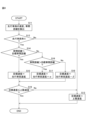
図4は、速度制御部331によって実行される速度制御処理の流れを示すフローチャートである。図示した処理は、一定の時間間隔毎に繰り返し実行される。
Figure 4 is a flowchart showing the flow of the speed control process executed by the
速度制御部331は、まず、先行車両の速度及び先行車両との車間距離を検出する(ステップS11)。具体的には、速度制御部331は、まず、車外カメラ12によって撮影された画像又は測距センサ13によって得られた距離情報に基づいて、車両100の周りを走行している他の車両を認識する。他の車両の認識は、ニューラルネットワーク(NN)、サポートベクターマシン(SVM)といった、公知のパターン認識手法によって行われる。また、速度制御部331は、車外カメラ12によって撮影された画像又は測距センサ13によって得られた距離情報に基づいて、認識された他車両の速度及び認識された他車両と車両100との車間距離とを算出する。
The
次いで、速度制御部331は、車両100が走行している走行車線に先行車両が存在するか否かを判定する(ステップS12)。具体的には、速度制御部331は、車外カメラ12によって撮影された画像に基づいて、又は測位センサ14によって測定された自己位置情報とストレージ装置15に記憶されている地図情報とに基づいて、車両100の走行している車線の形状を認識し、認識した車線の形状とステップS11において認識した他車両の位置情報とに基づいて、車両100の走行車線に先行車両が存在するか否かを判定する。ステップS12において車両100の走行車線に先行車両が存在すると判定された場合には、速度制御部331は、車両100の目標速度を後述する上限速度設定部334によって算出された上限速度に設定する(ステップS13)。
Next, the
一方、ステップS12において車両100の走行車線に先行車両が存在すると判定された場合には、速度制御部331は、車両100と先行車両との車間距離が目標車間距離とほぼ同一であるか否かを判定する(ステップS14)。目標車間距離は、予め設定された一定値であってもよいし、ドライバによって予め設定された一定値であってもよい。或いは、目標車間距離は、車両100の速度などのパラメータに応じて変化する値であってもよい(例えば、車両100の速度が速いほど長い)。
On the other hand, if it is determined in step S12 that a preceding vehicle is present in the driving lane of
ステップS14において車両100と先行車両との車間距離が目標車間距離とほぼ同一であると判定された場合には、速度制御部331は、目標速度を先行車両の速度とほぼ同一の速度に設定する(ステップS15)。
If it is determined in step S14 that the distance between
一方、ステップS14において車両100と先行車両との車間距離が目標車間距離とは異なると判定された場合には、速度制御部331は、車間距離が目標車間距離よりも長いか否かを判定する(ステップS16)。ステップS16において車間距離が目標車間距離よりも長いと判定された場合には、速度制御部331は、目標速度を先行車両の速度よりも速い速度に設定する(ステップS17)。一方、ステップS16において車間距離が目標車間距離よりも短いと判定された場合には、速度制御部331は、目標速度を先行車両の速度よりも遅い速度に設定する(ステップS18)。
On the other hand, if it is determined in step S14 that the distance between
ステップS15、S17及びS18において目標速度が先行車両の速度に基づいて設定されると、速度制御部331は、設定された目標速度が、上限速度設定部334によって算出された上限速度以下であるか否かを判定する(ステップS19)。設定された目標速度が上限速度以下であると判定された場合には、目標速度は変更されずに維持される。一方、ステップS19において、設定された目標速度が上限速度よりも速いと判定された場合には、速度制御部331は、目標速度を上限速度に設定する(ステップS13)。
When the target speed is set based on the speed of the preceding vehicle in steps S15, S17, and S18, the
車両100のECU21は、車両100の速度がこのようにして設定された目標速度になるように車両アクチュエータ20を制御する。したがって、現在の車両100の速度が目標速度よりも遅いときには、ECU21は、車両100が加速するように車両アクチュエータ20を制御する。特に、ECU21は、予め定められた上限加速度以下の加速度で車両100を加速させるように車両アクチュエータ20を制御する。一方、現在の車両100の速度が目標速度よりも速いときには、ECU21は、車両100が減速するように車両アクチュエータ20を制御する。特に、ECU21は、予め定められた上限減速度以下の減速度で車両100を減速させるように車両アクチュエータ20を制御する。
The
<上限速度の設定>
次に、上述した車両100の速度制御において用いられる上限速度の設定処理について説明する。図5は、上限速度の設定処理の流れを概略的に示すフローチャートである。図5に示した上限速度の設定処理は一定の時間間隔毎に実行される。
<Setting the upper limit speed>
Next, a description will be given of the process for setting the upper limit speed used in the speed control of the
上限速度の設定処理では、上限速度設定部334は、まず、基準上限速度を取得する(ステップS21)。基準上限速度は、例えば、HMIを介して予めユーザに設定された一定の速度であり、設定された基準上限速度は、ストレージ装置15に記憶されている。上限速度設定部334は、ストレージ装置15から基準上限速度を取得する。
In the upper limit speed setting process, the upper limit
なお、基準上限速度は、必ずしも一定の速度でなくてもよく、例えば車両100が走行している道路の種類などに応じて変化する速度であってもよい。この場合、ストレージ装置15には道路の種類毎に基準上限速度が記憶される。そして、上限速度設定部334は、測位センサ14の出力及びストレージ装置15に記憶された地図情報などに基づいて現在走行している道路の種類を特定すると共に、特定された道路の種類に対応する基準上限速度をストレージ装置15から取得する。
The reference upper speed limit does not necessarily have to be a constant speed, and may be a speed that changes depending on, for example, the type of road on which the
上限速度の設定処理では、次いで、上限速度設定部334が、横G上限速度を算出する横G上限速度の算出処理を行う(ステップS22)。横G上限速度は、車両100がカーブ道路を走行すると車両100お横加速度が上限横加速度(車両100に加わることが許容される横加速度の上限値)になるような車両100の速度である。横G上限速度の算出処理の具体的な手順については後述する(図6参照)。
In the process of setting the upper limit speed, the upper limit
次いで、上限速度の設定処理では、上限速度設定部334は、再加速上限速度を算出する再加速上限速度の算出処理を行う(ステップS23)。ここで、本実施形態では、上限速度設定部334は、車両100が、自動車専用道路の本線に合流する連絡路又は自動車専用道路の本線から分岐する連絡路(以下、これらをまとめて単に「連絡路」という)を走行しているときに、車両100が一時的に基準上限速度よりも低い再加速上限速度未満にまで減速されたときには、その後、車両100の上限速度を再加速上限速度に設定する。ステップS23では、このような再加速上限速度が算出される。なお、上限速度設定部334は、同一の連絡路の走行中に車両100の速度が一時的に再加速上限速度未満にまで減速されていないときには、再加速上限速度の算出処理の結果として再加速上限速度を算出しない。再加速上限速度の算出処理の具体的な手順については後述する(図9参照)。
Next, in the upper limit speed setting process, the upper limit
基準上限速度が取得され且つ横G上限速度が算出されると共に場合によっては再加速上限速度も算出されると、上限速度設定部334は、このようにして取得又は算出された基準上限速度、横G上限速度及び再加速上限速度のうち最も遅い速度を上限速度に設定する(ステップS24)。この結果、車両100の目標速度が、基準上限速度、横G上限速度又は再加速上限速度よりも速い速度に設定されることがなくなる。
When the reference upper limit speed is acquired, the lateral G upper limit speed is calculated, and in some cases the re-acceleration upper limit speed is also calculated, the upper limit
なお、本実施形態では、車両100の上限速度は、基準上限速度、横G上限速度及び再加速上限速度のうち最も遅い速度に設定される。しかしながら、車両100の上限速度は、基準上限速度及び横G上限速度のうち遅い方の速度に設定されてもよい。この場合には、上限速度設定部334は、再加速上限速度を算出しない。或いは、車両100の上限速度は、横G上限速度及び再加速上限速度のうち遅い方の速度に設定されてもよい。この場合には、上限速度設定部334は、基準上限速度を取得しない。加えて、車両100の上限速度は、横G上限速度に設定されてもよい。この場合、上限速度設定部334は、基準上限速度を取得せず、且つ、再加速上限速度を算出しない。したがって、上限速度設定部334は、基本的に横G上限速度を上限速度として設定する。そして、上限速度設定部334は、横G上限速度が基準上限速度又は再加速上限速度よりも速いときには、基準上限速度又は再加速上限速度を上限速度として設定してもよい。
In this embodiment, the upper limit speed of the
また、本実施形態では、基準上限速度の取得(ステップS21)、横G上限速度の算出(ステップS22)、再加速上限速度の算出(ステップS23)がこの順番で行われる。しかしながら、これら処置は必ずしもこの順番に行われる必要はなく、どのような順番で行われもよいし、同時に行われてもよい。 In addition, in this embodiment, the acquisition of the reference upper limit speed (step S21), the calculation of the lateral G upper limit speed (step S22), and the calculation of the re-acceleration upper limit speed (step S23) are performed in this order. However, these steps do not necessarily have to be performed in this order, and may be performed in any order or simultaneously.
<横G上限速度の算出>
次に、図5のステップS22で行われる横G上限速度の算出処理について説明する。図6は、横G上限速度の算出処理の流れを示すフローチャートである。図示した横G上限速度の算出処理は、図5に示した上限速度の設定処理にて、ステップS22に到達する毎に実行される。
<Calculation of maximum lateral G speed>
Next, the calculation process of the lateral G upper limit speed performed in step S22 of Fig. 5 will be described. Fig. 6 is a flowchart showing the flow of the calculation process of the lateral G upper limit speed. The calculation process of the lateral G upper limit speed shown in the figure is executed every time step S22 is reached in the setting process of the upper limit speed shown in Fig. 5.
横G上限速度の算出処理では、まず、上限横加速度設定部332が、車両100が走行する予定の道路の種類を特定する(ステップS31)。上述したように、本実施形態では、自動的な速度制御は、車両100が自動車専用道路の走行中に実行される。したがって、上限横加速度設定部332は、車両100が走行する予定の道路(以下、単に「走行予定の道路」という)が自動車専用道路の中のどの種類の道路であるかを特定する。具体的には、上限横加速度設定部332は、走行予定の道路が自動車専用道路の本線、自動車専用道路の連絡路のいずれであるかを特定する。加えて、上限横加速度設定部332は、走行予定の道路が自動車専用道路の本線であるときには、出口までの距離が所定の距離以下の道路であるか否かを特定する。また、上限横加速度設定部332は、走行予定の道路が自動車専用道路の連絡路であるときには、その連絡路が自動車専用道路の出口へ向かう連絡路であるか否かを特定する。
In the calculation process of the lateral G upper limit speed, first, the upper limit lateral
上限横加速度設定部332は、例えば、測位センサ14によって測定された自己位置情報を、ストレージ装置15に記憶されている地図情報に照合することで、走行予定の道路の種類を特定する。加えて、上限横加速度設定部332は、自己位置情報及び地図情報に加えて又はこれらの代わりに、車外カメラ12によって生成された画像に基づいて、走行予定の道路の種類を特定してもよい。この場合、例えば、画像認識処理により生成された画像内の区画線を認識すると共に、認識された区画線によって把握される車線の数に基づいて走行予定の道路の種類を特定してもよい。
The upper limit lateral
次いで上限横加速度設定部332は、走行予定の道路の種類に応じて、上限横加速度を設定する(ステップS32)。上限横加速度は、車両100がカーブ道路を走行する予定であるときに、車両100に加わることが許容される横加速度の上限値である。車両100に大きな横加速度が加わると、車両100の乗員は不安を感じることから、上限横加速度は、基本的に乗員が不安を感じることのないような値に設定される。本実施形態では、上限横加速度は、道路の種類ごとに予め定められた一定値である。
Next, the upper limit lateral
具体的には、本実施形態では、上限横加速度設定部332は、車両100が自動車専用道路の連絡路を走行するときの上限横加速度を、車両100が自動車専用道路の本線を走行するときの上限加速度よりも低く設定する。具体的には、例えば、車両100が連絡路を走行するときの上限横加速度が0.2Gに設定され、車両100が本線を走行するときの上限横加速度が0.3Gに設定される。
Specifically, in this embodiment, the upper limit lateral
ここで、一般に、乗員は道路幅が狭いほど、同一の横加速度に対して不安を感じやすい。また、自動車専用道路の連絡路は本線に比べて一般に道路幅が狭い。したがって、乗員は、同一の横加速度が車両100に加わったときには、車両100が連絡路を走行する場合は、車両100が本線を走行する場合に比べて乗員は不安を感じやすい。これに対して、本実施形態では、車両100が連絡路を走行するときの上限横加速度を車両100が本線を走行するときの上限加速度よりも低く設定することで、車両100が連絡路を走行するときに乗員が不安を感じることを抑制することができる。
In general, the narrower the road width, the more likely the occupant is to feel uneasy with the same lateral acceleration. Also, the width of an access road on a motorway is generally narrower than that of a main road. Therefore, when the same lateral acceleration is applied to the
また、本実施形態では、上限横加速度設定部332は、車両100が自動車専用道路の出口に向かう連絡路を走行するときの上限横加速度を、車両100が本線に合流する連絡路(すなわち、自動車専用道路の出口に向かわない連絡路)を走行するときの上限横加速度よりも低く設定する。具体的には、例えば、車両100が自動車専用道路の出口に向かう連絡路を走行するときの上限横加速度を、車両100が本線に合流する連絡路を走行するときの上限横加速度の8割程度又はそれ以下に設定する。
In addition, in this embodiment, the upper limit lateral
加えて、本実施形態では、上限横加速度設定部332は、連絡路のない本線出口までの距離が所定の基準距離以下の本線(すなわち、出口付近の本線)を走行するときの上限横加速度を、本線出口までの距離が基準距離よりも長い本線(すなわち、出口付近以外の本線)を走行するときの上限横加速度よりも低く設定する。具体的には、連絡路のない本線出口までの距離が基準距離以下の本線を走行するときの上限横加速度を、本線出口までの距離が基準距離よりも長い本線を走行するときの上限横加速度の8割程度又はそれ以下に設定する。なお、基準距離は、本線出口に備えて一般にドライバが減速を開始するような距離であり、例えば、300mである。
In addition, in this embodiment, the upper limit lateral
ここで、自動車専用道路の出口には料金所があるため、出口付近では車両100の速度を大幅に低下させる必要がある。また、自動車専用道路の出口に料金所がない場合であっても、自動車専用道路の出口に続く一般道では、車両100の速度を低下させる必要がある。したがって、自動車専用道路の出口付近では、車両100の速度を低下させることが必要になる。本実施形態では、自動車専用道路の出口に向かう連絡路を走行するときの上限横加速度を低く設定することにより、道路の状況に合わせて違和感なく車両100の速度を下げることができる。また、自動車専用道路の出口において運転交代を行う場合には、自動車専用道路の出口付近において車両100の速度を低下させることにより、ドライバへの運転交代をより安全に行うことができるようになる。
Here, since there is a toll booth at the exit of the expressway, it is necessary to significantly reduce the speed of the
上限横加速度設定部332によって上限横加速度が設定されると、道路曲率取得部333が、車両100が走行する予定の道路の曲率を取得する(ステップS33)。道路曲率取得部333は、例えば、現在の地点から300m先までの車両100が走行する予定の道路の曲率を取得する。走行予定の道路は、例えば、ECU21によって別途算出され、道路曲率取得部333は、算出された走行予定の道路と、各道路についての曲率情報を含む地図情報とから、走行予定の道路の曲率を取得する。
Once the upper limit lateral acceleration is set by the upper limit lateral
具体的には、ECU21は、HMI16を介して入力された目的地情報、車両100の周辺環境、測位センサ14によって測定された自己位置、及びストレージ装置15に記憶されている地図情報に基づいて、車両100の走行予定の道路を算出する。特に、本実施形態では、車両100が走行予定の道路が複数の車線を有する場合には、ECU21によって算出される走行予定の道路の情報には、車両100が走行する予定の車線の情報が含まれていてもよい。
Specifically, the
ストレージ装置15に記憶された地図情報は、各道路の各地点毎の曲率情報を含む。特に、地図情報は、複数の車線を有する道路については、各車線の各地点毎に、その車線の曲率情報を含んでいてもよい。いずれにせよ、道路曲率取得部333は、走行予定の道路の曲率を車両100の進行方向に沿って離散された点群データとして取得する。
The map information stored in the
図7は、本線Rmから連絡路Rcが分岐している自動車専用道路の例を概略的に示す図である。図7に示した例では、連絡路Rcは、本線Rmから分岐した後に、屈曲角が90度のカーブ道路を有する。このカーブ道路は、曲率が徐々に大きくなるクロソイド領域Xと、曲率が一定に維持される曲率一定領域Yと、曲率が徐々に小さくなるクロソイド領域Zとを有する。したがって、この場合、道路曲率取得部333は、クロソイド領域Xについては徐々に大きくなる曲率を離散的に取得し、曲率一定領域Yについては一定の曲率を離散的に取得し、クロソイド領域Zについては徐々に小さくなる曲率を離散的に取得する。
Figure 7 is a schematic diagram showing an example of an expressway where a connecting road Rc branches off from a main road Rm. In the example shown in Figure 7, the connecting road Rc has a curved road with a bending angle of 90 degrees after branching off from the main road Rm. This curved road has a clothoid region X where the curvature gradually increases, a constant curvature region Y where the curvature is maintained constant, and a clothoid region Z where the curvature gradually decreases. Therefore, in this case, the road
なお、本実施形態では、道路曲率取得部333は、上限横加速度設定部332によって上限横加速度が設定された後に、走行予定の道路の曲率を取得している。しかしながら、道路曲率取得部333は、上限横加速度設定部332によって上限横加速度が設定される前に、又は上限横加速度を設定するのと同時に、走行予定の道路の曲率を取得してもよい。また、本実施形態では、道路曲率取得部333は、走行予定の道路の曲率を取得している。しかしながら、道路曲率取得部333は、走行予定の道路の曲率に関する曲率パラメータであれば、曲率半径など、他の曲率パラメータを取得してもよい。したがって、本実施形態では、横G上限速度は、走行予定の道路の曲率パラメータの値に基づいて算出されるといえる。
In this embodiment, the road
車両100の上限横加速度が設定されると共に走行予定の道路の曲率が取得されると、上限速度設定部334は、走行予定の道路の各地点における横G上限速度を算出する(ステップS34)。走行予定の道路の各地点における横G上限速度は、基本的に、走行予定の道路の各地点の曲率に基づいて、その道路の各地点を車両100が走行すると車両100の横加速度が上限横加速度になるように算出される。以下、図8を参照して、上限速度設定部334における横G上限速度の算出手法を具体的に説明する。
Once the upper limit lateral acceleration of the
図8は、車両100が図7に示したような連絡路Rcを走行する予定であるときの、走行予定の道路の曲率及び横G上限速度を示す図である。図8の横軸は、車両100の現在地点からの距離を表している。図中の曲率に関して、実線は、現在地点に対する実際の曲率の推移(道路曲率取得部333によって取得された曲率の推移)を表している。したがって、曲率は、領域Xにおいて徐々に大きくなり、領域Yにおいて一定に維持され、領域Zにおいて徐々に小さくなる。
Figure 8 is a diagram showing the curvature and upper limit lateral G speed of the road along which the
本実施形態では、上限速度設定部334は、横G上限速度を算出するにあたって、ステップS33で取得された、走行予定の道路の曲率を補正する。具体的には、上限速度設定部334は、カーブ道路において曲率が最大となる領域が拡がるように、走行予定の曲率を補正する。図8に示した例では、曲率が最大となっている領域Yの前後に予め定められた所定距離Δdを加えた領域が、カーブ道路において曲率が最大となる領域になるように、走行予定の道路の曲率が補正される。その結果、走行予定の道路の補正後の曲率は、図8に破線で示したように推移する。
In this embodiment, when calculating the lateral G upper limit speed, the upper limit
上限速度設定部334は、このようにして算出された走行予定の道路の補正後の曲率と、走行予定の道路の上限横加速度とに基づいて算出される。例えば、各地点での横G上限速度Vgは、各地点の上限横加速度aをその地点の補正後の曲率cで除算したものの平方根とされる(Vg=(a/c)1/2)。このようにして算出された横G上限速度は、図8において実線で示されている。
The upper limit
<再加速上限速度の算出>
ところで、車両100が連絡路を走行している際には、速度制御部331は、急なカーブ道路の走行中に車両100の横加速度を制限するために、車両100の速度を基準上限速度未満にまで減速させることがある。また、速度制御部331は、車両100が連絡路を走行している際に、車両100の前の遅い先行車両に追従して、車両100の速度を基準上限速度未満にまで減速させることがある。本実施形態では、このような場合に、速度制御部331は、急なカーブ道路が直線的な道路に変化したり、遅い先行車両がいなくなったりしても、車両100の上限速度を基準上限速度よりも低い再加速上限速度以下に設定する。以下では、図9を参照して、再加速上限速度の算出方法について説明する。
<Calculation of upper re-acceleration speed limit>
Incidentally, when the
図9は、図5のステップS23で行われる、再加速上限速度の算出処理の流れを示すフローチャートである。図示した再加速上限速度は、図5に示した上限速度の設定処理にて、ステップS23に到達する毎に実行される。 Figure 9 is a flowchart showing the flow of the process of calculating the re-acceleration upper limit speed, which is performed in step S23 of Figure 5. The re-acceleration upper limit speed shown in the figure is executed each time step S23 is reached in the process of setting the upper limit speed shown in Figure 5.
再加速上限速度の算出処理では、まず、上限速度設定部334が、車両100が現在走行中の道路の種類を特定する(ステップS41)。道路の種類の特定は、図6のステップS31と同様に、例えば、測位センサ14によって測定された自己位置情報及びストレージ装置15に記憶されている地図情報に基づいて行われる。
In the process of calculating the re-acceleration upper limit speed, first, the upper limit
次いで、上限速度設定部334は、ステップS41において特定された走行中の道路の種類に基づいて、車両100が連絡路を走行中であるか否かを判定する(ステップS42)。ステップS42において、車両100は連絡路を走行中でない、すなわち本線を走行中であると判定された場合には、上限速度設定部334は、再加速上限速度の算出処理の結果としては再加速上限速度を算出せずにリセットする(ステップS43)。
Next, the upper limit
一方、ステップS42において、車両100は連絡路を走行中であると判定された場合には、上限速度設定部334は、再加速上限速度を算出する(ステップS44)。再加速上限速度は、基準上限速度よりも低い予め定められた速度である。本実施形態では、道路の種類と再加速上限速度との関係が予めストレージ装置15に格納されている。そして、上限速度設定部334は、ステップS41において特定された走行中の道路の種類と、ストレージ装置に格納されている関係とに基づいて再加速上限速度を算出する。
On the other hand, if it is determined in step S42 that the
特に、本実施形態では、車両100が自動車専用道路の出口へ向かう連絡路を走行しているときの再加速上限速度は、本線に合流する連絡路を走行しているときの再加速上限速度よりも低く算出される。ここで、上述したように、自動車専用道路の出口付近では、車両100の速度を低下させる必要がある。本実施形態によれば、自動車専用道路の出口に向かう連絡路を走行するときの再加速上限速度を低く算出することにより、道路の状況に合わせて違和感なく車両100の速度を下げることができる。
In particular, in this embodiment, the re-acceleration upper limit speed when the
次いで、上限速度設定部334は、車両100の速度が、再加速上限速度未満になるまで減速されたか否かを判定する(ステップS45)。車両100の速度は、例えば車両100の走行状態センサ11によって検出される。ステップS45において、車両100の速度が再加速上限速度以上であると判定された場合、すなわち連絡路において車両100はそれほど減速されていないと判定された場合には、上限速度設定部334は再加速上限速度の算出処理の結果としては再加速上限速度を算出せずにリセットする(ステップS43)。したがって、車両100の速度が再加速上限速度以上であるときには、再加速上限速度は設定されず、よって図5のステップS24では基準上限速度及び横G上限速度のうち遅い方の速度が上限速度に設定される。
Next, the upper limit
一方、ステップS45において、車両100の速度が再加速上限速度未満であると判定された場合には、上限速度設定部334は、再加速上限速度をリセットせずに、ステップS44において算出された値のまま維持する。したがって、この場合、図5のステップS24では、基準上限速度、横G上限速度及び再加速上限速度のうち最も遅い速度が上限速度に設定される。この結果、本実施形態では、連絡路を走行中に横加速度が再加速上限速度未満になるまで車両を減速した後に再度加速する場合、横G上限速度がこの再加速上限速度よりも速いときには、再加速上限速度が上限速度として設定されることになる。
On the other hand, if it is determined in step S45 that the speed of the
ここで、一般に、車両100が本線から連絡路に侵入したときは車両100の速度は比較的速く、連絡路を走行していくに従って徐々に速度が遅くなっていく。このため、連絡路を走行中に車両100の速度が一旦遅くなると、ドライバはその後に車両100が元の速度まで加速することに違和感を感じる。本実施形態によれば、連絡路を走行中に車両100の速度が何らかの障害で一旦遅くなると、その後その障害がなくなっても連絡路の走行中に車両100の速度が元の速度にまで戻ることはないため、ドライバが違和感を感じることが抑制される。
In general, when
なお、上記実施形態では、上限速度設定部334は、ステップS44では車両100の速度が再加速上限速度未満まで減速されたか否かを判定している。しかしながら、上限速度設定部334は、ステップS44では、再加速上限速度よりも低い所定の速度未満まで減速されたか否かを判定してもよい。これにより、ヒステリシスを持たせることができる。
In the above embodiment, the upper limit
また、上限速度設定部334は、ステップS44において車両100の速度が多段的な再加速上限速度未満まで減速されたか否かを判定し、多段的な再加速上限速度未満まで減速されたと判定した場合には、再加速上限速度を多段的に設定してもよい。例えば、上限速度設定部334は、車両100の速度が第1速度未満且つ第2速度以上の速度まで減速された場合には再加速上限速度を第1速度に設定し、車両100の速度が第2速度未満且つ第3速度以上の速度まで減速された場合には再加速上限速度を第2速度に設定し、車両100の速度が第3速度未満まで減速された場合には再加速上限速度を第3速度に設定してもよい。
In addition, the upper limit
<作用・効果>
上述したように、乗員は道路幅が狭いほど、同一の横加速度に対して不安を感じやすい。また、自動車専用道路の連絡路は本線に比べて一般に道路幅が狭い。本実施形態では、車両100が連絡路を走行するときの上限横加速度を車両100が本線を走行するときの上限加速度よりも低く設定することで、車両100が連絡路を走行するときに乗員が不安を感じることを抑制することができる。したがって、本実施形態によれば、車両が走行している道路の種類によらずに、車両の横加速度が適切になるように車両の速度を制御することができる。
<Action and Effects>
As described above, the narrower the road width, the more likely the occupant feels uneasy for the same lateral acceleration. Also, the width of the connecting road of a motorway is generally narrower than that of the main road. In this embodiment, the upper limit lateral acceleration when the
以上、本発明に係る好適な実施形態を説明したが、本発明はこれら実施形態に限定されるものではなく、特許請求の範囲の記載内で様々な修正及び変更を施すことができる。 The above describes preferred embodiments of the present invention, but the present invention is not limited to these embodiments, and various modifications and changes can be made within the scope of the claims.
1 自動速度制御システム
21 ECU
31 通信インターフェース
32 メモリ
33 プロセッサ
100 車両
331 速度制御部
332 上限横加速度設定部
333 道路曲率取得部
334 上限速度設定部
1 Automatic
31
Claims (6)
前記車両の走行中に許容される横加速度の上限値である上限横加速度を設定する上限横加速度設定部と、
前記車両が走行する予定の道路の曲率に関する曲率パラメータの値を取得する道路曲率取得部と、
前記道路の曲率パラメータの値に基づいて該道路を前記車両が走行すると該車両の横加速度が前記上限横加速度になるような車両の速度を算出し、算出された速度を上限速度として設定する上限速度設定部と、
前記上限速度以下になるように車両の速度を制御する速度制御部と、を有し、
前記上限横加速度設定部は、前記車両が自動車専用道路の本線に合流する連絡路又は本線から分岐する連絡路を走行するときの上限横加速度を、前記車両が自動車専用道路の本線を走行するときの上限横加速度よりも低く設定し、
前記上限速度設定部は、上限横加速度になるような車両の速度が前記上限横加速度とは無関係に設定された所定の基準上限速度よりも速いときには、基準上限速度を上限速度として設定し、
前記連絡路を走行中に前記車両の速度が所定の再加速上限速度未満になるまで車両を減速した後に再度加速する場合、前記上限横加速度になるような車両の速度が前記再加速上限速度よりも速いときには、該再加速上限速度を上限速度として設定し、
前記再加速上限速度は、前記基準上限速度よりも低い、自動速度制御装置。 An automatic speed control device that automatically controls the speed of a vehicle,
an upper limit lateral acceleration setting unit that sets an upper limit lateral acceleration that is an upper limit value of a lateral acceleration permitted while the vehicle is traveling;
a road curvature acquisition unit that acquires a value of a curvature parameter related to a curvature of a road on which the vehicle is scheduled to travel;
an upper limit speed setting unit that calculates a vehicle speed based on a curvature parameter value of the road such that a lateral acceleration of the vehicle becomes the upper limit lateral acceleration when the vehicle travels on the road, and sets the calculated speed as an upper limit speed;
a speed control unit that controls the speed of the vehicle so that the speed is equal to or less than the upper limit speed,
the upper limit lateral acceleration setting unit sets an upper limit lateral acceleration when the vehicle travels on a connecting road merging into a main line of a motorway or a connecting road branching off from the main line to be lower than an upper limit lateral acceleration when the vehicle travels on the main line of the motorway,
the upper limit speed setting unit sets the reference upper limit speed as the upper limit speed when the vehicle speed that corresponds to the upper limit lateral acceleration is faster than a predetermined reference upper limit speed that is set independently of the upper limit lateral acceleration,
when the vehicle is decelerated while traveling on the connecting road until the speed of the vehicle becomes less than a predetermined re-acceleration upper limit speed and then accelerates again, if the vehicle speed at which the upper limit lateral acceleration is reached is faster than the re-acceleration upper limit speed, the re-acceleration upper limit speed is set as the upper limit speed,
The automatic speed control device , wherein the re-acceleration upper limit speed is lower than the reference upper limit speed .
前記上限速度設定部は、前記車両が前記出口へ向かう連絡路を走行しているときの再加速上限速度を、本線に合流する連絡路を走行するときの再加速上限速度よりも低く設定する、請求項1に記載の自動速度制御装置。 the vehicle is a vehicle in which automatic control of the vehicle's speed is stopped at an exit of a motorway,
2. The automatic speed control device according to claim 1, wherein the upper limit speed setting unit sets a re-acceleration upper limit speed when the vehicle is traveling on a connecting road toward the exit lower than a re-acceleration upper limit speed when the vehicle is traveling on a connecting road merging into a main line.
前記上限横加速度設定部は、前記車両が前記出口へ向かう連絡路を走行するときの上限横加速度を、本線に合流する連絡路を走行するときの上限横加速度よりも低く設定する、請求項1又は2に記載の自動速度制御装置。 the vehicle is a vehicle in which automatic control of the vehicle's speed is stopped at an exit of a motorway,
3. The automatic speed control device according to claim 1, wherein the upper limit lateral acceleration setting unit sets an upper limit lateral acceleration when the vehicle is traveling on a connecting road toward the exit to be lower than an upper limit lateral acceleration when the vehicle is traveling on a connecting road that merges into a main road.
前記車両の走行中に許容される横加速度の上限値である上限横加速度を設定することと、
前記車両が走行する予定の道路の曲率に関する曲率パラメータの値を取得することと、
前記道路の曲率パラメータの値に基づいて該道路を前記車両が走行すると該車両の横加速度が前記上限横加速度になるような車両の速度を算出し、算出された速度を上限速度として設定することと、
前記上限速度以下になるように車両の速度を制御することと、を含み、
前記車両が自動車専用道路の本線に合流する連絡路又は本線から分岐する連絡路を走行するときの上限横加速度は、前記車両が自動車専用道路の本線を走行するときの上限横加速度よりも低く、
上限横加速度になるような車両の速度が前記上限横加速度とは無関係に設定された所定の基準上限速度よりも速いときには、基準上限速度を上限速度として設定することと、
前記連絡路を走行中に前記車両の速度が所定の再加速上限速度未満になるまで車両を減速した後に再度加速する場合、前記上限横加速度になるような車両の速度が前記再加速上限速度よりも速いときには、該再加速上限速度を上限速度として設定することと、を更に含み、
前記再加速上限速度は、前記基準上限速度よりも低い、自動速度制御方法。 An automatic speed control method for automatically controlling a speed of a vehicle, comprising:
Setting an upper limit lateral acceleration, which is an upper limit value of lateral acceleration permitted during traveling of the vehicle;
Obtaining a value of a curvature parameter relating to a curvature of a road along which the vehicle is to travel;
calculating a vehicle speed based on a curvature parameter value of the road such that a lateral acceleration of the vehicle when the vehicle travels on the road becomes the upper limit lateral acceleration, and setting the calculated speed as an upper limit speed;
and controlling the speed of the vehicle so that it is equal to or less than the upper limit speed.
The upper limit lateral acceleration when the vehicle is traveling on a connecting road merging into a main line of a motorway or a connecting road branching off from the main line is lower than the upper limit lateral acceleration when the vehicle is traveling on the main line of the motorway,
When the vehicle speed that results in the upper limit lateral acceleration is faster than a predetermined reference upper limit speed that is set independently of the upper limit lateral acceleration, setting the reference upper limit speed as the upper limit speed;
and when the vehicle is decelerated while traveling on the connecting road until the speed of the vehicle becomes less than a predetermined re-acceleration upper limit speed and then accelerates again, if the vehicle speed that results in the upper limit lateral acceleration is faster than the re-acceleration upper limit speed, setting the re-acceleration upper limit speed as an upper limit speed,
The automatic speed control method , wherein the re-acceleration upper limit speed is lower than the reference upper limit speed .
前記車両の走行中に許容される横加速度の上限値である上限横加速度を設定し、
前記車両が走行する予定の道路の曲率に関する曲率パラメータの値を取得し、
前記道路の曲率パラメータの値に基づいて該道路を前記車両が走行すると該車両の横加速度が前記上限横加速度になるような車両の速度を算出し、算出された速度を上限速度として設定し、
前記上限速度以下になるように車両の速度を制御する、ことをコンピュータに実行させ、
前記車両が自動車専用道路の本線に合流する連絡路又は本線から分岐する連絡路を走行するときの上限横加速度は、前記車両が自動車専用道路の本線を走行するときの上限横加速度よりも低く、
上限横加速度になるような車両の速度が前記上限横加速度とは無関係に設定された所定の基準上限速度よりも速いときには、基準上限速度を上限速度として設定し、
前記連絡路を走行中に前記車両の速度が所定の再加速上限速度未満になるまで車両を減速した後に再度加速する場合、前記上限横加速度になるような車両の速度が前記再加速上限速度よりも速いときには、該再加速上限速度を上限速度として設定する、ことを更にコンピュータに実行させ、
前記再加速上限速度は、前記基準上限速度よりも低い、自動速度制御プログラム。 An automatic speed control program for automatically controlling a vehicle speed, comprising:
setting an upper limit lateral acceleration, which is an upper limit value of the lateral acceleration permitted while the vehicle is traveling;
obtaining a value of a curvature parameter relating to a curvature of a road along which the vehicle is to travel;
calculating a vehicle speed such that a lateral acceleration of the vehicle becomes the upper limit lateral acceleration when the vehicle travels on the road based on a curvature parameter value of the road, and setting the calculated speed as an upper limit speed;
controlling the speed of the vehicle so that the speed is equal to or less than the upper limit speed;
The upper limit lateral acceleration when the vehicle is traveling on a connecting road merging into a main line of a motorway or a connecting road branching off from the main line is lower than the upper limit lateral acceleration when the vehicle is traveling on the main line of the motorway,
When the vehicle speed that results in the upper limit lateral acceleration is faster than a predetermined reference upper limit speed that is set independently of the upper limit lateral acceleration, the reference upper limit speed is set as the upper limit speed;
and when the vehicle decelerates while traveling on the connecting road until the speed of the vehicle becomes less than a predetermined re-acceleration upper limit speed and then accelerates again, if the vehicle speed that results in the upper limit lateral acceleration is faster than the re-acceleration upper limit speed, setting the re-acceleration upper limit speed as an upper limit speed;
The re-acceleration upper limit speed is lower than the reference upper limit speed .
Priority Applications (3)
| Application Number | Priority Date | Filing Date | Title |
|---|---|---|---|
| JP2021052274A JP7517222B2 (en) | 2021-03-25 | 2021-03-25 | Automatic speed control device, automatic speed control method, and automatic speed control program |
| US17/690,144 US12384244B2 (en) | 2021-03-25 | 2022-03-09 | Automatic speed control device, automatic speed control method, and automatic speed control program |
| CN202210288245.3A CN115195720B (en) | 2021-03-25 | 2022-03-22 | Automatic speed control device, automatic speed control method and automatic speed control program |
Applications Claiming Priority (1)
| Application Number | Priority Date | Filing Date | Title |
|---|---|---|---|
| JP2021052274A JP7517222B2 (en) | 2021-03-25 | 2021-03-25 | Automatic speed control device, automatic speed control method, and automatic speed control program |
Publications (2)
| Publication Number | Publication Date |
|---|---|
| JP2022149924A JP2022149924A (en) | 2022-10-07 |
| JP7517222B2 true JP7517222B2 (en) | 2024-07-17 |
Family
ID=83362945
Family Applications (1)
| Application Number | Title | Priority Date | Filing Date |
|---|---|---|---|
| JP2021052274A Active JP7517222B2 (en) | 2021-03-25 | 2021-03-25 | Automatic speed control device, automatic speed control method, and automatic speed control program |
Country Status (3)
| Country | Link |
|---|---|
| US (1) | US12384244B2 (en) |
| JP (1) | JP7517222B2 (en) |
| CN (1) | CN115195720B (en) |
Families Citing this family (6)
| Publication number | Priority date | Publication date | Assignee | Title |
|---|---|---|---|---|
| US20210347360A1 (en) * | 2020-05-11 | 2021-11-11 | Micron Technology, Inc. | Automated driving actions for determined driving conditions |
| JP7415975B2 (en) * | 2021-02-12 | 2024-01-17 | トヨタ自動車株式会社 | Vehicle driving support system and vehicle driving support method |
| JP7611102B2 (en) * | 2021-09-17 | 2025-01-09 | 株式会社クボタ | Work vehicle and vehicle speed management system |
| WO2023100698A1 (en) * | 2021-12-02 | 2023-06-08 | 株式会社デンソー | Control device for vehicle, and control method for vehicle |
| JP7700718B2 (en) * | 2022-04-05 | 2025-07-01 | トヨタ自動車株式会社 | Deceleration support device |
| CN119116959B (en) * | 2024-11-11 | 2025-04-25 | 福瑞泰克智能系统有限公司 | Data-driven adaptive curve speed planning control method, system and vehicle |
Citations (5)
| Publication number | Priority date | Publication date | Assignee | Title |
|---|---|---|---|---|
| JP2001012958A (en) | 1999-07-02 | 2001-01-19 | Sumitomo Electric Ind Ltd | Vehicle driving support device |
| JP2010089700A (en) | 2008-10-10 | 2010-04-22 | Hitachi Automotive Systems Ltd | Traveling control device |
| JP2018203084A (en) | 2017-06-06 | 2018-12-27 | 株式会社Subaru | Travel control device for vehicle |
| JP2020082749A (en) | 2018-11-15 | 2020-06-04 | トヨタ自動車株式会社 | Vehicle control apparatus |
| WO2020230308A1 (en) | 2019-05-15 | 2020-11-19 | 日産自動車株式会社 | Driving assistance method and driving assistance device |
Family Cites Families (18)
| Publication number | Priority date | Publication date | Assignee | Title |
|---|---|---|---|---|
| JP3508414B2 (en) * | 1996-08-28 | 2004-03-22 | 日産自動車株式会社 | Inter-vehicle distance control type constant speed traveling device |
| JP3412553B2 (en) | 1999-04-09 | 2003-06-03 | 株式会社デンソー | Automatic driving control device |
| JP4639997B2 (en) * | 2005-02-18 | 2011-02-23 | トヨタ自動車株式会社 | Vehicle deceleration control device |
| JP4800735B2 (en) * | 2005-10-14 | 2011-10-26 | 株式会社小松製作所 | Engine speed control device for work vehicle |
| JP4586795B2 (en) * | 2006-12-07 | 2010-11-24 | トヨタ自動車株式会社 | Vehicle control device |
| JP5257923B2 (en) * | 2008-01-31 | 2013-08-07 | 株式会社アドヴィックス | Vehicle motion control device |
| JP5494814B2 (en) * | 2010-09-29 | 2014-05-21 | トヨタ自動車株式会社 | Vehicle control device |
| EP2762372A1 (en) * | 2011-09-27 | 2014-08-06 | Toyota Jidosha Kabushiki Kaisha | Vehicle drive force control apparatus |
| JP6262685B2 (en) * | 2015-04-23 | 2018-01-17 | トヨタ自動車株式会社 | Vehicle control apparatus equipped with continuously variable transmission |
| JP6319192B2 (en) * | 2015-05-29 | 2018-05-09 | トヨタ自動車株式会社 | Vehicle speed limiter |
| JP6752875B2 (en) | 2016-02-26 | 2020-09-09 | 日立オートモティブシステムズ株式会社 | Travel control device |
| JP6489044B2 (en) * | 2016-03-11 | 2019-03-27 | トヨタ自動車株式会社 | Driving force control device |
| WO2017168541A1 (en) * | 2016-03-29 | 2017-10-05 | 本田技研工業株式会社 | Automatic driving control device |
| US11254351B2 (en) * | 2017-03-13 | 2022-02-22 | Steering Solutions Ip Holding Corporation | Steering mode selection using machine learning |
| JP6528336B2 (en) * | 2017-06-02 | 2019-06-12 | 本田技研工業株式会社 | Vehicle control system and vehicle control method |
| KR102337011B1 (en) * | 2018-03-20 | 2021-12-13 | 모빌아이 비젼 테크놀로지스 엘티디 | Systems and methods for navigating a vehicle |
| US11465626B2 (en) * | 2019-02-06 | 2022-10-11 | Toyota Jidosha Kabushiki Kaisha | Virtualized driver assistance |
| JP7210357B2 (en) * | 2019-03-28 | 2023-01-23 | 本田技研工業株式会社 | VEHICLE CONTROL DEVICE, VEHICLE CONTROL METHOD, AND PROGRAM |
-
2021
- 2021-03-25 JP JP2021052274A patent/JP7517222B2/en active Active
-
2022
- 2022-03-09 US US17/690,144 patent/US12384244B2/en active Active
- 2022-03-22 CN CN202210288245.3A patent/CN115195720B/en active Active
Patent Citations (5)
| Publication number | Priority date | Publication date | Assignee | Title |
|---|---|---|---|---|
| JP2001012958A (en) | 1999-07-02 | 2001-01-19 | Sumitomo Electric Ind Ltd | Vehicle driving support device |
| JP2010089700A (en) | 2008-10-10 | 2010-04-22 | Hitachi Automotive Systems Ltd | Traveling control device |
| JP2018203084A (en) | 2017-06-06 | 2018-12-27 | 株式会社Subaru | Travel control device for vehicle |
| JP2020082749A (en) | 2018-11-15 | 2020-06-04 | トヨタ自動車株式会社 | Vehicle control apparatus |
| WO2020230308A1 (en) | 2019-05-15 | 2020-11-19 | 日産自動車株式会社 | Driving assistance method and driving assistance device |
Also Published As
| Publication number | Publication date |
|---|---|
| US12384244B2 (en) | 2025-08-12 |
| CN115195720A (en) | 2022-10-18 |
| JP2022149924A (en) | 2022-10-07 |
| CN115195720B (en) | 2025-05-16 |
| US20220305909A1 (en) | 2022-09-29 |
Similar Documents
| Publication | Publication Date | Title |
|---|---|---|
| JP7517222B2 (en) | Automatic speed control device, automatic speed control method, and automatic speed control program | |
| US11731637B2 (en) | Driver assistance system | |
| US11738751B2 (en) | Speed control device | |
| JP7047824B2 (en) | Vehicle control unit | |
| US10001782B2 (en) | Target pathway generating device and driving control device | |
| CN112703141A (en) | Driving assistance method and driving assistance device | |
| JP7379033B2 (en) | Driving support method and driving support device | |
| CN121697674A (en) | Vehicle control device, vehicle control method and computer program for vehicle control | |
| JP7031747B2 (en) | Vehicle control method and vehicle control device | |
| JP7435513B2 (en) | Vehicle control device and vehicle control method | |
| CN115214667B (en) | Vehicle control device, storage medium and vehicle control method | |
| JP7540375B2 (en) | Vehicle control device, vehicle control method, and vehicle control computer program | |
| JP2020138610A (en) | Vehicle display control device, vehicle display control method, vehicle display control program | |
| EP4060643B1 (en) | Traffic signal recognition method and traffic signal recognition device | |
| JP7517221B2 (en) | Automatic speed control device, automatic speed control method, and automatic speed control program | |
| JP7635749B2 (en) | Vehicle control device, vehicle control computer program, and vehicle control method | |
| CN115145260B (en) | Data correction device, data correction method, data correction program, and vehicle | |
| JP7614820B2 (en) | Operation control method and operation control device | |
| US20220260386A1 (en) | Vehicle control device | |
| JP2022007157A (en) | Vehicle control device | |
| US12384354B2 (en) | Vehicle control device, storage medium for storing computer program for vehicle control, and method for controlling vehicle | |
| JP2020091148A (en) | Display controller and display control program | |
| JP7827586B2 (en) | Vehicle control device, vehicle control computer program, and vehicle control method | |
| JP2023154345A (en) | Vehicle control device, vehicle control computer program, and vehicle control method |
Legal Events
| Date | Code | Title | Description |
|---|---|---|---|
| A621 | Written request for application examination |
Free format text: JAPANESE INTERMEDIATE CODE: A621 Effective date: 20230516 |
|
| A977 | Report on retrieval |
Free format text: JAPANESE INTERMEDIATE CODE: A971007 Effective date: 20240124 |
|
| A131 | Notification of reasons for refusal |
Free format text: JAPANESE INTERMEDIATE CODE: A131 Effective date: 20240220 |
|
| A521 | Request for written amendment filed |
Free format text: JAPANESE INTERMEDIATE CODE: A523 Effective date: 20240417 |
|
| TRDD | Decision of grant or rejection written | ||
| A01 | Written decision to grant a patent or to grant a registration (utility model) |
Free format text: JAPANESE INTERMEDIATE CODE: A01 Effective date: 20240604 |
|
| A61 | First payment of annual fees (during grant procedure) |
Free format text: JAPANESE INTERMEDIATE CODE: A61 Effective date: 20240617 |
|
| R150 | Certificate of patent or registration of utility model |
Ref document number: 7517222 Country of ref document: JP Free format text: JAPANESE INTERMEDIATE CODE: R150 |