JP7500285B2 - Refrigerators and output devices - Google Patents
Refrigerators and output devices Download PDFInfo
- Publication number
- JP7500285B2 JP7500285B2 JP2020100259A JP2020100259A JP7500285B2 JP 7500285 B2 JP7500285 B2 JP 7500285B2 JP 2020100259 A JP2020100259 A JP 2020100259A JP 2020100259 A JP2020100259 A JP 2020100259A JP 7500285 B2 JP7500285 B2 JP 7500285B2
- Authority
- JP
- Japan
- Prior art keywords
- imaging device
- storage chamber
- door
- image
- refrigerator
- Prior art date
- Legal status (The legal status is an assumption and is not a legal conclusion. Google has not performed a legal analysis and makes no representation as to the accuracy of the status listed.)
- Active
Links
Images


Classifications
-
- F—MECHANICAL ENGINEERING; LIGHTING; HEATING; WEAPONS; BLASTING
- F25—REFRIGERATION OR COOLING; COMBINED HEATING AND REFRIGERATION SYSTEMS; HEAT PUMP SYSTEMS; MANUFACTURE OR STORAGE OF ICE; LIQUEFACTION SOLIDIFICATION OF GASES
- F25D—REFRIGERATORS; COLD ROOMS; ICE-BOXES; COOLING OR FREEZING APPARATUS NOT OTHERWISE PROVIDED FOR
- F25D23/00—General constructional features
Landscapes
- Engineering & Computer Science (AREA)
- Chemical & Material Sciences (AREA)
- Combustion & Propulsion (AREA)
- Physics & Mathematics (AREA)
- Mechanical Engineering (AREA)
- Thermal Sciences (AREA)
- General Engineering & Computer Science (AREA)
- Cold Air Circulating Systems And Constructional Details In Refrigerators (AREA)
Description
本発明は、冷蔵庫および出力装置に関する。 The present invention relates to a refrigerator and an output device.
冷蔵庫において、貯蔵品の在庫管理などを目的として、カメラにより冷蔵室内(庫内)を撮影するようにしたものが提案されている。特許文献1には、「カメラは、冷蔵庫本体の上面の前部に、前方へ突出した状態で設けられていて、第1のモータによりX方向(前後方向)へ、第2のモータによりY方向(左右方向)へ回転される。冷蔵室の扉が開放されると、カメラは冷蔵室内を撮影する第1の撮影位置に自動的に向きを変え、冷蔵室内を撮影する。」ことが記載されている。
For refrigerators, a camera has been proposed to take pictures of the interior of the refrigerator (fridge), for the purpose of inventory management of stored goods, etc.
特許文献1の記載の冷蔵庫において、制御手段は、開放された扉に対応してカメラの撮影方向を自動的に制御して自動的に撮影を行わせることができる。このため、開放された扉に対応する貯蔵室の状態を自動的に撮影することができ、使用者がカメラを逐一操作する必要はないとしているが、扉の開閉の度に、カメラの撮影方向を可動することは、製品の信頼性に好ましくない。
In the refrigerator described in
また、特許文献1には、カメラを可動方式ではなく、固定式のものも記載されている。すなわち、特許文献1の固定式のものは、アームの先端部に設けられたカメラは、冷蔵庫本体側で、かつ斜め下向きに向けられた状態で固定されていて、駆動手段となる第1及び第2のモータは設けられておらず、また、カメラカバーには、冷蔵室用及びドアポケット用凹レンズは設けられていない。カメラのレンズは広角レンズであり、その視野内には、扉が開放された冷蔵室内と、野菜室等からそれぞれ引き出された各引出し内が入っていて、これらの範囲を1枚で撮影することができることが記載されている(特許文献1の第3実施例)。
本願の発明者らはその撮像範囲を検討したところ、カメラを固定にした場合に、冷蔵室(貯蔵室)内の内部まで適切に撮影できないことが判明した。 The inventors of this application investigated the imaging range and found that if the camera was fixed, it would not be possible to properly capture images of the inside of the refrigerator (storage room).
本発明は、前記した従来の課題を解決するものであり、冷蔵室(貯蔵室)内を適切に撮影することができる冷蔵庫および出力装置を提供することを目的とする。 The present invention aims to solve the above-mentioned problems of the conventional technology and provide a refrigerator and output device that can properly capture images of the inside of the refrigerator compartment (storage compartment).
前記目的を達成するため、本発明の冷蔵庫は、前方が開口した貯蔵室を形成する箱体と、貯蔵室の外に設けられてレンズを備えた撮像装置と、撮像装置の撮像領域内であって前記貯蔵室の外に設けられた鏡と、を有し、前記鏡は、前記レンズより前方に位置して前記貯蔵室内に向かって配置されており、前記撮像装置は、前方に位置する前記鏡による前記貯蔵室内の虚像及び後方に位置する前記貯蔵室内の実像を撮像し、前記虚像は、前記貯蔵室内のうち、前記実像で死角になる領域を含むことを特徴とする。本発明のその他の態様については、後記する実施形態において説明する。
In order to achieve the above object, the refrigerator of the present invention has a box body forming a storage compartment with an opening at the front, an imaging device provided outside the storage compartment and equipped with a lens , and a mirror provided outside the storage compartment within an imaging area of the imaging device , the mirror is disposed forward of the lens and facing the inside of the storage compartment, the imaging device captures a virtual image of the inside of the storage compartment by the mirror located in front and a real image of the inside of the storage compartment located behind the mirror, and the virtual image includes an area within the storage compartment that is a blind spot of the real image . Other aspects of the present invention will be described in the embodiments described later.
本発明によれば、冷蔵室内を適切に撮影することができる。 The present invention makes it possible to properly photograph the interior of a refrigerator.
本発明を実施するための形態(実施形態)について、適宜図面を参照しながら詳細に説明する。
<<第1実施形態>>
図1は、第1実施形態に係る冷蔵庫100を示す正面図である。図2Aは、第1実施形態に係る冷蔵庫100を示す側面図である。図2Bは、第1実施形態に係る撮像装置30を収納した場合の側面図である。図3は、第1実施形態に係る冷蔵庫100の扉を開けた状態を示す正面図である。図4は、第1実施形態に係る冷蔵庫100の扉を開けた状態を示す上面図である。なお、以下の説明では、6ドアの冷蔵庫100を例に挙げて説明するが、6ドアに限定されるものではない。
DETAILED DESCRIPTION OF THE PREFERRED EMBODIMENTS The present invention will now be described in detail with reference to the accompanying drawings, in which: FIG.
<<First embodiment>>
FIG. 1 is a front view showing the
図1に示すように、冷蔵庫100の断熱箱体(箱体10)は、上方から冷蔵室1、左右に併設された製氷室2と上段冷凍室3、野菜室4、下段冷凍室5の順番で貯蔵室を有している。冷蔵庫100はそれぞれの貯蔵室の開口を開閉するドアを備えている。これらのドアは、冷蔵室1の開口を開閉する、左右に分割された回転式の冷蔵室ドア1a,1bと、製氷室2、上段冷凍室3、野菜室4、下段冷凍室5の開口をそれぞれ開閉する引き出し式の製氷室ドア2a、上段冷凍室ドア3a、野菜室ドア4a、下段冷凍室ドア5aである。なお、野菜室4と下段冷凍室5との位置は、上下配置を変更してもよい。また、製氷室2と上段冷凍室3と下段冷凍室5とを合わせて冷凍室7と呼ぶ。
As shown in FIG. 1, the insulated box (box 10) of the
冷蔵室ドア1a,1bを冷蔵庫100に固定するために、ドアヒンジ(符号省略)が冷蔵室1の上部および下部に設けられている。図3、図4に示すように、冷蔵室ドア1a,1bを開閉すると、ドア収納部11a(扉収納部a),11b(扉収納部b)が設けられている。
To secure the
冷蔵室1は、庫内を冷蔵温度帯(0℃以上)の例えば平均的に4℃程度にした冷蔵貯蔵室である。冷凍室7は、庫内を冷凍温度帯(0℃未満)の例えば平均的に-18℃程度にした冷凍貯蔵室である。野菜室4は、庫内を冷蔵温度帯の例えば平均的に6℃程度の冷蔵貯蔵室で、食品の乾燥を抑えた冷蔵貯蔵室である。
冷蔵庫100は、庫内を撮影するための撮像装置30が貯蔵室の外側上部の略中央部に配置されている。すなわち、冷蔵庫100の箱体(断熱箱体)の上方、略中央部に設けられている。箱体のドアが閉じられている場合に撮像装置30のレンズ34(図6A、図6B参照)は、貯蔵室の開口縁面10aよりも前方、好ましくは冷蔵室ドア1a,1b(扉)よりも前方に位置する。すなわち、撮像装置30を貯蔵室の外に設け、撮像範囲内に鏡37(図6A、図6B参照)を一つ又は複数配置することにより、撮像装置30の突出量を最小限にすることで外観を損ねず、ドア収納部11a,11bを含めた庫内の状況を俯瞰的に撮像できる。なお、鏡37は、レンズ34よりも前方に配置されている。この撮像装置30の詳細については、後記する。
In the
また、撮像装置30は、前後に移動するスライドする機構(貯蔵室開口に垂直な方向にスライドする機構)を有し、冷蔵庫100の扉前面を跨り前後に移動可能である。例えば図2Bに示すように、扉前面より後方又は貯蔵室開口の縁面より後方に移動可能であるため、梱包時には奥行寸法には影響しない。また、輸送トラックへの冷蔵庫の積載数量が減少することはなく、設置後においても、撮像装置30を使用しない場合には収納し撮像範囲を目隠しすることができる。目隠しによって、カメラの撮像領域が自身の生活範囲に常に入っていること等を好ましく思わないユーザにも配慮した構成とすることができる。同様に、撮像範囲のうち庫外側の領域の一部が鏡によって目隠しされており、これもそのようなユーザに好適である。
The
冷蔵室ドア1bには、撮像装置30により手動で撮影する際に使用される撮影ボタン39(ユーザからの撮影指令を受付ける撮影指令受付部)が設けられている。撮影ボタン39は、冷蔵室ドア1aや箱体又は扉のその他の領域に設けられていてもよい。
The
図5Aは、第1実施形態に係る撮像装置30を示す正面図である。図5Bは、第1実施形態に係る撮像装置30を示す側面図である。図5Cは、第1実施形態に係る撮像装置30を示す側断面図(図5AのAA断面図)である。図6Aは、第1実施形態に係る撮像装置30を示す斜視図である。図6Bは、第1実施形態に係る撮像装置30の撮像部の詳細を示す側断面図である。
Fig. 5A is a front view showing the
撮像装置30は、ケース部31と蓋部32から構成されており、ケース部31の前方には、カメラ33(撮像部)や魚眼レンズであるレンズ34を有している。レンズ34は、図6Aに示すように、遮光壁35で囲まれている。遮光壁35の近傍に、複数の照明部38を有する。また、レンズ34の近傍(レンズ34よりも前方)に鏡37が設けられている。
The
ケース部31の内部には、図5Cに示すように、制御SoC41および無線LANユニット42が格納されている。制御SoC41(System on a chip)は、集積回路の1個のチップ上に、プロセッサコアをはじめ一般的なマイクロコントローラが持つような機能の他、応用目的の機能なども集積し、連携してシステムとして機能するよう設計されている集積回路である。なお、制御SoC41は集積回路の一例であり、他の集積回路等でも代替可能である。
As shown in FIG. 5C, the
貯蔵室の外に設けられた撮像装置30がドア収納部11a,11bと、好ましくは貯蔵室内部を俯瞰的に撮像する。さらに、この撮像装置30の撮像範囲内であって貯蔵室の外に設けられた鏡37は、撮像用のレンズ34の前方に鏡面を貯蔵室内に向かって配置される。
An
この鏡37は、レンズ34による撮像範囲の中で貯蔵室並びに、扉収納部を撮像する範囲には重ならないように部分的に配置されているのが好ましい。つまり、本実施形態では鏡37はレンズ34よりも前方に配置されている。このことにより、撮像装置30の撮像範囲を邪魔することなく、さらには撮像装置30のレンズ34による撮像範囲だけでは撮像できない範囲を鏡37による虚像で補うことができる。つまり、カメラ33は、レンズ34による撮像で死角になる部分を、鏡37を介して(鏡37に映った像で)撮影できるようになる。また、この鏡37を設けることにより、撮像装置30が本体前方に突出する量を最小限にしながら、庫内状況をより俯瞰的に撮像することができ、外観を損ねることもない。また、冷蔵庫100の本体からカメラ33や制御SoC41に接続する配線(電源供給等の配線)の長さを短くすることができる。
It is preferable that the
撮像装置30の特徴をさらに説明する。
(1)撮像装置30に用いるカメラ33は、180度以上の広角度であり、魚眼レンズを有することで、扉を開けた際に庫内全体を俯瞰的に視認することができる。
(2)撮像装置30のカメラ用のレンズ34は冷蔵庫の扉前面よりも前に位置することで、野菜室4および下段冷凍室5の引き出し部6のみを開けた際でも庫内の状態を撮影することができる。
(3)撮像装置30は、撮影範囲内に鏡37を有し、この鏡37は映し出す虚像が撮影範囲を拡大する役割を有する。
The features of the
(1) The
(2) The
(3) The
(4)撮像装置30は、照明部38を備え、撮影に適した照度に調整出来る庫外の照明部38を使用して撮影することで、視認性の高い画像を得ることができる。冷蔵庫内に設けられた照明は比較的照度が高いため、カメラで撮影した際に収納物の反射が強く、撮影画像は白飛びしたものになる。このため、本実施形態では、撮影時には、庫内照明を消灯し、庫外の照明部38を点灯して撮影する。詳細は、図13、図14で後記する。
また、照明部38の照明は、庫内、扉を開けた際の扉収納部11a,11b、第2貯蔵室(例えば、野菜室4、下段冷凍室5)の全体を照射するように指向性を持たせている。
(5)撮像装置30は、遮光壁35を有することにより、照明部38の直接光は撮影範囲に入らないことで、反射や白飛びを抑えた視認性の高い画像を得ることができる。
(6)撮像装置30の照明部38とレンズ34の間に直接光を遮る遮光壁35を設けることで、照明の設置位置をレンズ34に極力近づけることができるため、コンパクトな外形に収めることができ、さらにはレンズ34の傷付き防止効果も得ることができる。
(4) The
In addition, the lighting from the
(5) The
(6) By providing a light-shielding
(7)撮像装置30は、前後に移動するスライドする機構を有し、冷蔵庫100の扉前面を跨り前後に移動可能であるため、梱包時には奥行寸法には影響しない。また、輸送トラックに対する冷蔵庫の積載数量が減少することはなく、設置後においても、撮像装置30を使用しない場合には収納し撮像範囲を目隠しすることができる。
(8)撮像装置30は、通信ユニット(無線LANユニット42)を備え、通信ユニットから発信された画像データは、例えば、家庭内の無線ルータ(例えば、家庭内ルータ53(図12参照)を介してサーバ54(図12参照)に供給される。詳細については、後記する。
(9)撮像装置30は、電源供給と撮影指令を伝達する通信回路が冷蔵庫本体側と繋がっている。冷蔵庫本体は商用電源等から電力供給を受けている。撮像装置30の電源は冷蔵庫本体を介して商用電源から受け取ることができる。なお、撮像装置30を充電池で駆動するようにしてもよい。
(7)
(8) The
(9) The
図7は、第1実施形態に係る撮像装置30の適用効果を示す説明図である。図7は、効果説明をわかりやすくするため、図5Bや図5Cよりも鏡37の大きさを大きく強調して図示している。貯蔵室の奥を撮影するためには撮像装置30のカメラ33のレンズ34を貯蔵室前面壁(貯蔵室の開口縁面10a)よりも極力前方に配置することが好ましい。これは,貯蔵室前面壁端部が上方からの撮影領域の死角となるためである。
Figure 7 is an explanatory diagram showing the effect of applying the
しかし,輸送性,外観意匠性,使いやすさを考慮すれば前方への出張り量は極力抑えることが望ましい。本実施形態によれば、鏡37を前方に配置することにより,鏡37に反射して映る虚像は、図7に示すようにカメラ33での撮影領域よりも貯蔵室奥側に拡大する効果をもたらす。鏡37の高さhをより大きくすれば、さらに撮影領域を拡大することが可能である。
However, when considering transportability, external design, and ease of use, it is desirable to minimize the amount of forward protrusion. According to this embodiment, by arranging
本実施形態の撮像例を比較例(鏡37を有しない場合)と比較して説明する。
図8Aは、比較例の撮像装置による撮像例を示す説明図である。図8Bは、比較例の撮像装置による撮像例の画像処理を示す説明図である。図8A、図8Bは、鏡37を有しない場合である。図8Aは、庫内画像補正処理前の画像であり、魚眼レンズのレンズ34を介した画像は、実像画像である。
An example of imaging according to this embodiment will be described in comparison with a comparative example (where the
Fig. 8A is an explanatory diagram showing an example of imaging by an imaging device of a comparative example. Fig. 8B is an explanatory diagram showing image processing of an example of imaging by an imaging device of a comparative example. Fig. 8A and Fig. 8B are examples in which a
図8Bは、本実施形態の所定の画像処理を行い庫内画像補正処理後(鏡無し)の画像である。冷蔵庫100を使用するユーザが庫内のものを確認しやすい画像に変換したものである。図8Bをみると、扉収納部a、扉収納部b、貯蔵庫c内のものが実像としてみることができる。
Figure 8B shows an image after interior image correction processing (without a mirror) using the specified image processing of this embodiment. The image has been converted to make it easier for the user of
図9Aは、第1実施形態に係る撮像装置による撮像例を示す説明図である。図9Bは、第1実施形態に係る撮像装置による撮像例の画像処理を示す説明図である。図9A、図9Bは、本実施形態の鏡37を有する場合である。図9Aは、庫内画像補正処理前の画像であり、魚眼レンズのレンズ34を介した画像は、図8Aに示した実像と、鏡37を介した貯蔵庫cの虚像(鏡37を介して撮像される画像)との合成画像である。
Figure 9A is an explanatory diagram showing an example of imaging by the imaging device according to the first embodiment. Figure 9B is an explanatory diagram showing image processing of an example of imaging by the imaging device according to the first embodiment. Figures 9A and 9B show the case where the
図9Bは、本実施形態の所定の画像処理を行った庫内画像補正処理後(鏡有り)の画像である。冷蔵庫100を使用するユーザが庫内のものを確認しやすい画像に変換したものである。図9Bをみると、扉収納部a、扉収納部bのものが実像として、貯蔵庫cのものは、鏡37を介した虚像と鏡37を介しない実像とを合成して、変換処理している。これにより、鏡37により特に上段において奥行方向の視認領域が拡大されている。具体的には、説明図は缶を例にしており,鏡があるとプルタブ(図示せず)が見える。この鏡37を拡大することでより視認領域を広げることが可能である。
Figure 9B shows an image after interior image correction processing (with mirror) performed using a specified image processing method according to this embodiment. The image has been converted to make it easier for the user of the
図10は、第1実施形態に係る冷蔵庫100の引き出し部6を引き出した状態を示す側面図である。図11は、第1実施形態に係る冷蔵庫100の引き出し部6の撮像例を示す図である。庫内を撮影するための撮像装置30は、引き出し部6内を撮像することができる。図11は、野菜室4の引き出し部6の画像であるが、野菜の収納状態を把握することができる。
Figure 10 is a side view showing the state in which the
図12は、第1実施形態に係る冷蔵庫100の撮影システムを示す構成図である。ドア(扉)側のセンサとして、冷蔵室ドア1a,1b、製氷室ドア2a、上段冷凍室ドア3a、野菜室ドア4a、下段冷凍室ドア5aの開閉状態をそれぞれ検知するドアセンサ(図示せず)等も設けられている。
Figure 12 is a configuration diagram showing the imaging system of the
冷蔵庫100の上部には、制御装置の一部であるCPU(Central Processing Unit)、ROM(Read Only Memory)やRAM(Random Access Memory)等のメモリ、インターフェース回路等を搭載したメインマイコン52(制御装置、制御部)が配置されている。メインマイコン52は、ドアセンサまたは撮影ボタン39からの情報を基に、庫内の撮影を行う撮影システムの制御を行う。また、メインマイコン52は、撮像装置30への電源供給も行う。
A main microcomputer 52 (control device, control section) is located on top of the
メインマイコン52は、自動撮影設定時、ドアセンサから扉の開き角度等の情報に基づき、所定角度以上を検知すると、制御SoC41に撮影指令を送信する。制御SoC41は、カメラ33に撮影指示を出し、カメラ33から未処理の画像データを取得する。制御SoC41は、未処理の画像データを、例えば、図9Bのように、実像と虚像とを組み合わせる画像処理を行う。他方、メインマイコン52は、手動撮影設定時、撮影ボタン39が操作されたことを検知すると、制御SoC41に撮影指令を送信する。その後の処理は、自動撮影設定時と同様である。
When the
撮像装置30は、前記したように、家庭内ルータ53と接続できる無線LANユニット42が設けられている。この無線LANユニット42が設けられることで、制御Soc41で処理済み庫内画像データを、家庭内ルータ53を介してサーバ54に送信することができる。サーバ54は、ユーザの所有するスマートフォン55等のモバイルデバイスやパーソナルコンピュータ等からの庫内画像表示要求に応じて、庫内画像データを送信する。これにより、ユーザは、庫内の状況を把握することができる。
As described above, the
図13は、第1実施形態に係る手動撮影設定時の処理を示すフローチャートである。適宜、図12を参照して説明する。メインマイコン52は、設定装置(図示せず)からの設定がカメラ撮影設定時(カメラ設定ON)の場合(S31)、ドアセンサによりドアの開きが有るか否か(扉の開?)を判定し(S32)、ドアの開きがある場合(S32,Yes)、S33に進む。一方、ドアの開きが無い場合(S32,No)、メインマイコン52は、S32に戻る。
Figure 13 is a flowchart showing the process when manual photography is set according to the first embodiment. The description will be made with reference to Figure 12 as appropriate. When the setting from the setting device (not shown) is for camera photography setting (camera setting ON) (S31), the
S33において、メインマイコン52は、撮影ボタン39の操作(押下)が有るか否かを判定し、撮影ボタン39の押下がある場合(S33,Yes)、S34に進み、撮影ボタン39の押下が無い場合(S33,Yes)、S32に戻る。
In S33, the
S34において、メインマイコン52は、制御SoC41に撮影指令をし、庫内の照明の消灯と庫外照明(照明部38)の点灯を行う(S35)。制御SoC41は、カメラ33に撮影指令して撮影する(S36)。そして、メインマイコン52は、庫内の照明の点灯と庫外照明(照明部38)の消灯を行う(S37)。
In S34, the
カメラ33は、制御SoC41に未処理画像データ(例えば、図9A)を送信し(S38)、制御SoC41は、庫内画像補正処理(画像処理)を実施する(S39)。具体的には、図9Bで説明したように、虚像と実像との合成画像を作成する。
The
制御SoC41は、処理済み画像データを、無線LANユニット42、家庭内ルータ53を介して、サーバ54に画像アップデートする(S40)。サーバ54は、画像がアップデートされたら、ユーザのモバイルデバイス等に通知する(S41)。
以上が手動撮影設定時の処理である。
The
The above is the process when manual shooting is set.
図14は、第1実施形態に係る自動撮影設定時の処理を示すフローチャートである。適時、図12を参照して説明する。なお、図13と同様の処理は説明を省略する。メインマイコン52は、設定装置(図示せず)からの設定がカメラ自動撮影設定時(カメラ自動設定ON)の場合(S31A)、ドアセンサによりドアの開きが有るか否か(扉の開?)を判定し(S32)、ドアの開きがある場合(S32,Yes)、S33に進む。一方、ドアの開きが無い場合(S32,No)、メインマイコン52は、S32に戻る。
Figure 14 is a flow chart showing the processing when automatic photography is set according to the first embodiment. Description will be made with reference to Figure 12 as appropriate. Note that description of the same processing as in Figure 13 will be omitted. When the setting from the setting device (not shown) is for automatic camera photography (automatic camera setting ON) (S31A), the
S33において、メインマイコン52は、ドアの開き角度が所定角度以上(例えば、扉角度85度以上)であるか否かを判定し(S33A)、ドアの開き角度が所定角度以上である場合(S33A,Yes)、S34に進み、ドアの開き角度が所定角度未満の場合(S33A,No)、S32に戻る。S34からS41は、図13と同様である。なお、S33Aにおいて、観音開きの冷蔵室1の場合、冷蔵室ドア1a,1bの内、少なくともどちらかのドアの開き角度が所定角度である場合(S33A,Yes)、S34に進む。
以上が自動撮影設定時の処理である。
In S33, the
The above is the process when automatic shooting is set.
冷蔵庫100の撮影システムの特徴をさらに説明する。
(1A)冷蔵庫の扉の開き角度を検知する検知部(例えば、メインマイコン52)を有し、検知部が所定角度(例えば、85度)以上と判定した場合に自動で撮影を行うことができる。
(2A)検知部が所定角度以上と判定した場合に庫内照明が消灯し、撮像装置30の照明が点灯することで、撮影に適切な照度に調整するだけでなく、使用者に撮影のタイミングを知らせる効果を有する。
(3A)冷蔵庫100の引き出し距離が一定以上になった際に検知する検知部(例えば、引き出し部6に設置されている)を有し、検知部により引き出しの操作を検知し自動で撮影を行うことで、野菜室や冷凍室の撮像範囲を概ね一定に保つことができる。
The features of the imaging system of the
(1A) The refrigerator has a detection unit (e.g., main microcontroller 52) that detects the opening angle of the refrigerator door, and can automatically take a photograph when the detection unit determines that the angle is equal to or greater than a predetermined angle (e.g., 85 degrees).
(2A) When the detection unit determines that the angle is equal to or greater than a predetermined angle, the interior lighting is turned off and the lighting of the
(3A) The
(4A)冷蔵庫の扉に撮影用釦(例えば、撮影ボタン39)を有し、ユーザが撮影用釦を押した際、庫内照明が消灯し、撮像装置30の照明が点灯した後に撮影が行われるため、撮影をしたタイミングを認知し易い。
(5A)撮影された画像は画像補正処理が行われ、広角度カメラによって歪んだ画像が補正されることにより、使用者の目線に近い画像を提供できる。
(6A)前記画像を使用者が携帯電話等を介して確認出来るアプリケーションサービスを有し、前記画像は、ドア(扉)、また前記引き出しに設けられた検知部により、撮影した画像がどの収納室の画像であるかを自動で判定することができる。
(4A) The refrigerator door has a button for photographing (e.g., photographing button 39). When the user presses the button for photographing, the interior lighting is turned off and the lighting of the
(5A) The captured image is subjected to image correction processing, and the distorted image captured by the wide-angle camera is corrected to provide an image that is close to the user's line of sight.
(6A) An application service is provided that allows a user to check the images via a mobile phone or the like, and a detection unit is provided on the door or the drawer to automatically determine which storage room the captured image belongs to.
<<第2実施形態>>
第1実施形態では、撮像装置30は、スライド機構を有することを説明したが、これに限定されるわけではない。第2実施形態では、二つ折り機構について説明する。
<<Second embodiment>>
In the first embodiment, the
図15Aは、第2実施形態に係る撮像装置の通常時の状態を示す説明図である。図15Bは、第2実施形態に係る撮像装置の収納途中の状態を示す説明図である。図15Cは、第2実施形態に係る撮像装置の収納時の状態を示す説明図である。 Fig. 15A is an explanatory diagram showing the normal state of the imaging device according to the second embodiment. Fig. 15B is an explanatory diagram showing the state of the imaging device according to the second embodiment in the middle of being stored. Fig. 15C is an explanatory diagram showing the state of the imaging device according to the second embodiment when it is stored.
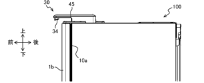
第2実施形態の冷蔵庫100(図1参照)は、前方が開口した貯蔵室を形成する箱体と、貯蔵室の外に設けられた撮像装置30と、開口に少なくとも垂直な方向に対して前記撮像装置30を移動可能に支持する支持部45(ヒンジ部)と、を備える。
The
図15A~図15Cに示すように、撮像装置30のカメラ33を有する先端部は、支持部45から二つ折りできるように構成されており、梱包時には奥行寸法には影響しないため、輸送トラックに対する冷蔵庫の積載数量が減少することはなく、設置後においても、撮像装置30を使用しない場合には収納し撮像範囲を目隠しすることができる。
As shown in Figures 15A to 15C, the tip of the
また、撮像装置30は、庫内を覗き込む方向にも公転(ヒンジ部まわりに円形軌跡で動く;軸まわりに公転)可能にする。円形軌跡中に箱体が存在することから、公転可能な角度は、公転面に直交する方向から観察した場合に360°未満である。この場合、撮像装置30に公転方向の力を付与できる駆動部を取付け、撮像時に冷蔵室等の庫内を覗き込む角度にするように制御してもよい。例えば、撮像時に、扉の移動軌跡内に撮像装置30が位置するようにできる。こうすることでより効果的に庫内を撮像でき、さらに撮像終了後は扉の移動軌跡外に復帰させたり、扉や貯蔵室の前方開口の縁面より後方にまで公転させて収納可能なことから、支持部45(ヒンジ部)とカメラとをつなぐアームを長くしやすいことが特徴である。
The
以上説明した本実施形態の冷蔵庫100は、次の特徴を有する。
本実施形態の冷蔵庫100は、前方が開口した貯蔵室を形成する箱体10と、貯蔵室の外に設けられた撮像装置30と、撮像装置30の撮像領域内であって貯蔵室の外に設けられ鏡37と、を有する(図1~図4、図7参照)。
The
The
撮像装置30が鏡37を撮像領域に含めて撮像した場合、撮像された鏡37による虚像は貯蔵室内を含んでいる(図8B参照)。
When the
撮像装置30は、レンズ34を備え、撮像装置30は、箱体10の上方に設けられ、レンズ34は貯蔵室の開口縁面10aよりも前方に位置する(図7参照)。
The
貯蔵室は観音開きの第1貯蔵室(例えば、冷蔵室1)と前後方向開きの第2貯蔵室(例えば、製氷室2、上段冷凍室3、野菜室4、下段冷凍室5)を少なくとも有し、撮像装置30が鏡37を撮像領域に含めて撮像した場合、撮像された鏡37による虚像は第1貯蔵室内または第2貯蔵室内を含むように、撮像装置30が位置する(図1~図4、図10参照)。
The storage compartments include at least a first storage compartment (e.g., refrigerator compartment 1) that opens like a double door and a second storage compartment (e.g., ice-making
撮像装置30は、レンズ34を備え、鏡37は、レンズ34の前方に鏡面を貯蔵室内に向けて配設される(図7参照)。
The
撮像装置30は、レンズ34を備え、レンズ34の周辺に、ひとつ又は複数の照明部38を備え、レンズ34と照明部38との間に遮光壁35を有する(図6A、図6B参照)。
The
撮像装置は、レンズ34を備え、レンズ34の周辺に、ひとつ又は複数の照明部38を備え、貯蔵室内に設けられた庫内灯を備え、撮像装置30の撮像は、庫内灯を消灯かつ照明部38を点灯した状態で行われる(図13、図14参照)。
The imaging device includes a
撮像装置30は、前後方向に可動である(図2A、図2B参照)。
The
撮像装置30は、軸まわりに公転可能である(図15A、図15B、図15C参照)。
The
冷蔵庫100が撮像した画像を出力する出力装置(例えば、制御SoC41)であって、撮像装置30の撮像領域に含まれた実像及び虚像を利用した1つの画像を出力する(図9B、図12参照)。
An output device (e.g., control SoC 41) that outputs images captured by the
冷蔵庫100は、貯蔵室の扉に、ユーザからの撮影指令を受付ける撮影指令受付部(例えば、撮影ボタン39)を有する。
The
なお、本発明は前記した第1実施形態および第2実施形態に限定されるものではなく、様々な変形例が含まれる。例えば、前記した実施形態は本発明を分かりやすく説明するために詳細に説明したものであり、必ずしも説明した全ての構成を備えるものに限定されるものではない。また、前記した実施形態の構成の一部について、他の構成の追加・削除・置換をすることが可能である。例えば、図3の撮影ボタン39は、冷蔵室ドア1aに設けられていてもよいし、引き出し部6の上面に設けられていてもよい。
The present invention is not limited to the first and second embodiments described above, and includes various modified examples. For example, the above-described embodiments have been described in detail to clearly explain the present invention, and the present invention is not necessarily limited to those having all of the configurations described. In addition, it is possible to add, delete, or replace some of the configurations of the above-described embodiments with other configurations. For example, the
1 冷蔵室(第1貯蔵室)
1a,1b 冷蔵室ドア
2 製氷室(第2貯蔵室)
2a 製氷室ドア
3 上段冷凍室(第2貯蔵室)
3a 上段冷凍室ドア
4 野菜室(第2貯蔵室)
4a 野菜室ドア
5 下段冷凍室(第2貯蔵室)
5a 下段冷凍室ドア
6 引き出し部
10 箱体
10a 開口縁面
11a,11b ドア収納部
30 撮像装置
31 ケース部
32 蓋部
33 カメラ(撮像部)
34 レンズ
35 遮光壁
37 鏡
38 照明部
39 撮影ボタン(撮影指令受付部)
41 制御SoC(出力装置)
42 無線LANユニット
45 支持部(ヒンジ部)
51 扉センサ
52 メインマイコン
53 家庭内ルータ
54 サーバ
55 スマートフォン
100 冷蔵庫
1 Refrigerator compartment (first storage compartment)
1a,
2a
3a
4a
5a
34
39 Shooting button (shooting command reception section)
41 Control SoC (output device)
42
51
Claims (8)
前記貯蔵室の外に設けられてレンズを備えた撮像装置と、
前記撮像装置の撮像領域内であって前記貯蔵室の外に設けられた鏡と、を有し、
前記鏡は、前記レンズより前方に位置して前記貯蔵室内に向かって配置されており、
前記撮像装置は、前方に位置する前記鏡による前記貯蔵室内の虚像及び後方に位置する前記貯蔵室内の実像を撮像し、
前記虚像は、前記貯蔵室内のうち、前記実像で死角になる領域を含む冷蔵庫。 A box body forming a storage chamber with an opening at the front;
an imaging device provided outside the storage chamber and equipped with a lens ;
a mirror provided within an imaging area of the imaging device and outside the storage chamber ;
The mirror is disposed forward of the lens and facing the inside of the storage chamber,
the imaging device captures a virtual image of the interior of the storage chamber by the mirror located in front of the imaging device and a real image of the interior of the storage chamber located in the rear of the imaging device;
The virtual image includes a region within the storage compartment that is a blind spot in the real image .
前記レンズと前記照明部との間に遮光壁を有する
ことを特徴とする請求項1に記載の冷蔵庫。 One or more illumination units are provided around the lens;
The refrigerator according to claim 1, further comprising a light-shielding wall between the lens and the lighting unit.
前記撮像装置は、前記貯蔵室の開口を開閉する扉が開された状態で、前記庫内灯を消灯して撮像を行うThe imaging device performs imaging with the interior light turned off in a state where a door for opening and closing the opening of the storage compartment is open.
ことを特徴とする請求項1に記載の冷蔵庫。2. The refrigerator according to claim 1 .
前記撮像装置の撮像は、前記庫内灯を消灯かつ前記照明部を点灯した状態で行われる
ことを特徴とする請求項3に記載の冷蔵庫。 The imaging device includes one or more illumination units,
The refrigerator according to claim 3, wherein the imaging device captures an image with the interior light turned off and the illumination unit turned on.
前記貯蔵室は前記貯蔵室としての観音開きの第1貯蔵室と、前後方向開きの第2貯蔵室を少なくとも有し、The storage chamber includes at least a first storage chamber that opens like a double door and a second storage chamber that opens in the front and rear directions,
前記撮像装置は、前記第1貯蔵室と前記第2貯蔵室をともに撮像可能であり、the imaging device is capable of imaging both the first storage chamber and the second storage chamber,
前記照明部は、前記第1貯蔵室と前記第2貯蔵室をともに照射するThe lighting unit illuminates both the first storage chamber and the second storage chamber.
ことを特徴とする請求項1に記載の冷蔵庫。2. The refrigerator according to claim 1 .
ことを特徴とする請求項1に記載の冷蔵庫。 The refrigerator according to claim 1 , wherein the imaging device is revolvable around an axis , and the lens is movable across a front opening of the storage compartment to both sides in front and behind the storage compartment.
前記撮像装置の撮像領域に含まれた実像及び虚像を利用した1つの画像を出力する出力装置。 An output device that outputs an image captured by the refrigerator according to claim 1,
An output device that outputs a single image using the real image and virtual image contained in the imaging area of the imaging device.
ことを特徴とする請求項1に記載の冷蔵庫。 The refrigerator according to claim 1 , further comprising an image capturing command receiving unit for receiving an image capturing command from a user on a side surface of the door of the storage compartment opposite to a rotation axis of the door .
Priority Applications (4)
| Application Number | Priority Date | Filing Date | Title |
|---|---|---|---|
| JP2020100259A JP7500285B2 (en) | 2020-06-09 | 2020-06-09 | Refrigerators and output devices |
| CN202080101856.1A CN115698611A (en) | 2020-06-09 | 2020-11-20 | Refrigerator and output device |
| PCT/JP2020/043316 WO2021250913A1 (en) | 2020-06-09 | 2020-11-20 | Refrigerator and output device |
| JP2024088935A JP2024103671A (en) | 2020-06-09 | 2024-05-31 | refrigerator |
Applications Claiming Priority (1)
| Application Number | Priority Date | Filing Date | Title |
|---|---|---|---|
| JP2020100259A JP7500285B2 (en) | 2020-06-09 | 2020-06-09 | Refrigerators and output devices |
Related Child Applications (1)
| Application Number | Title | Priority Date | Filing Date |
|---|---|---|---|
| JP2024088935A Division JP2024103671A (en) | 2020-06-09 | 2024-05-31 | refrigerator |
Publications (3)
| Publication Number | Publication Date |
|---|---|
| JP2021196069A JP2021196069A (en) | 2021-12-27 |
| JP2021196069A5 JP2021196069A5 (en) | 2023-03-07 |
| JP7500285B2 true JP7500285B2 (en) | 2024-06-17 |
Family
ID=78847183
Family Applications (2)
| Application Number | Title | Priority Date | Filing Date |
|---|---|---|---|
| JP2020100259A Active JP7500285B2 (en) | 2020-06-09 | 2020-06-09 | Refrigerators and output devices |
| JP2024088935A Pending JP2024103671A (en) | 2020-06-09 | 2024-05-31 | refrigerator |
Family Applications After (1)
| Application Number | Title | Priority Date | Filing Date |
|---|---|---|---|
| JP2024088935A Pending JP2024103671A (en) | 2020-06-09 | 2024-05-31 | refrigerator |
Country Status (3)
| Country | Link |
|---|---|
| JP (2) | JP7500285B2 (en) |
| CN (1) | CN115698611A (en) |
| WO (1) | WO2021250913A1 (en) |
Families Citing this family (9)
| Publication number | Priority date | Publication date | Assignee | Title |
|---|---|---|---|---|
| JP7353340B2 (en) * | 2021-10-19 | 2023-09-29 | 日立グローバルライフソリューションズ株式会社 | refrigerator |
| WO2023042504A1 (en) * | 2021-09-15 | 2023-03-23 | 日立グローバルライフソリューションズ株式会社 | Refrigerator |
| KR20230114951A (en) * | 2022-01-26 | 2023-08-02 | 비스타테크놀러지 주식회사 | Product inventory management system and method using reflector-camera structure |
| JP7615069B2 (en) * | 2022-02-08 | 2025-01-16 | 日立グローバルライフソリューションズ株式会社 | Refrigerator, refrigerator system, and camera unit |
| JP7623969B2 (en) | 2022-02-15 | 2025-01-29 | 日立グローバルライフソリューションズ株式会社 | Home appliances and refrigerators |
| JP7591529B2 (en) | 2022-02-15 | 2024-11-28 | 日立グローバルライフソリューションズ株式会社 | Home appliances and refrigerators |
| WO2023153075A1 (en) * | 2022-02-08 | 2023-08-17 | 日立グローバルライフソリューションズ株式会社 | Household appliance |
| JP7595039B2 (en) * | 2022-02-22 | 2024-12-05 | 日立グローバルライフソリューションズ株式会社 | Image management system, image management server, image management method, and image display control system manufacturing method |
| JP2025140258A (en) * | 2024-03-14 | 2025-09-29 | 日立グローバルライフソリューションズ株式会社 | refrigerator |
Citations (4)
| Publication number | Priority date | Publication date | Assignee | Title |
|---|---|---|---|---|
| JP2014240730A (en) | 2013-06-12 | 2014-12-25 | 株式会社東芝 | Refrigerator |
| JP2015111025A (en) | 2013-03-12 | 2015-06-18 | 株式会社東芝 | Refrigerator and camera device |
| WO2018069986A1 (en) | 2016-10-12 | 2018-04-19 | 三菱電機株式会社 | Refrigerator |
| CN110455027A (en) | 2019-07-16 | 2019-11-15 | 海信集团有限公司 | A kind of image collecting device and its refrigerator, control method |
Family Cites Families (8)
| Publication number | Priority date | Publication date | Assignee | Title |
|---|---|---|---|---|
| JP2003042626A (en) * | 2001-07-26 | 2003-02-13 | Toshiba Corp | refrigerator |
| US20130030552A1 (en) * | 2011-07-28 | 2013-01-31 | Bryan James Beckley | Optically-projected user interface for appliances |
| JP6391943B2 (en) * | 2013-03-12 | 2018-09-19 | 東芝ライフスタイル株式会社 | Refrigerator, camera device, internal image display program |
| JP6402353B2 (en) * | 2013-03-29 | 2018-10-10 | パナソニックIpマネジメント株式会社 | Refrigerator and refrigerator system |
| JP2014238217A (en) * | 2013-06-07 | 2014-12-18 | 株式会社東芝 | Refrigerator |
| JP2017206398A (en) * | 2016-05-16 | 2017-11-24 | デンカ株式会社 | Method for producing light transmissive hard substrate laminated body |
| JP6799958B2 (en) * | 2016-07-20 | 2020-12-16 | 三菱電機株式会社 | refrigerator |
| JP2019049386A (en) * | 2017-09-11 | 2019-03-28 | 日立アプライアンス株式会社 | Program for refrigerator and refrigerator system and terminal device |
-
2020
- 2020-06-09 JP JP2020100259A patent/JP7500285B2/en active Active
- 2020-11-20 WO PCT/JP2020/043316 patent/WO2021250913A1/en not_active Ceased
- 2020-11-20 CN CN202080101856.1A patent/CN115698611A/en active Pending
-
2024
- 2024-05-31 JP JP2024088935A patent/JP2024103671A/en active Pending
Patent Citations (4)
| Publication number | Priority date | Publication date | Assignee | Title |
|---|---|---|---|---|
| JP2015111025A (en) | 2013-03-12 | 2015-06-18 | 株式会社東芝 | Refrigerator and camera device |
| JP2014240730A (en) | 2013-06-12 | 2014-12-25 | 株式会社東芝 | Refrigerator |
| WO2018069986A1 (en) | 2016-10-12 | 2018-04-19 | 三菱電機株式会社 | Refrigerator |
| CN110455027A (en) | 2019-07-16 | 2019-11-15 | 海信集团有限公司 | A kind of image collecting device and its refrigerator, control method |
Also Published As
| Publication number | Publication date |
|---|---|
| CN115698611A (en) | 2023-02-03 |
| JP2024103671A (en) | 2024-08-01 |
| WO2021250913A1 (en) | 2021-12-16 |
| JP2021196069A (en) | 2021-12-27 |
Similar Documents
| Publication | Publication Date | Title |
|---|---|---|
| JP7500285B2 (en) | Refrigerators and output devices | |
| JP7675908B2 (en) | Imaging system and imaging device | |
| CN205245656U (en) | Cold storage and cold storage systems | |
| JP2003042626A (en) | refrigerator | |
| JP6359179B2 (en) | refrigerator | |
| CN110296568A (en) | Freezer and refrigerated merchandiser systems | |
| JP6655908B2 (en) | Refrigerators and programs | |
| JP2023112016A (en) | refrigerator | |
| JP2016023892A (en) | refrigerator | |
| JP7104087B2 (en) | refrigerator | |
| JP2019023563A (en) | refrigerator | |
| JP7595039B2 (en) | Image management system, image management server, image management method, and image display control system manufacturing method | |
| JP6500251B2 (en) | refrigerator | |
| JP6681555B2 (en) | refrigerator | |
| US12316983B2 (en) | Refrigerator | |
| JP2021096066A (en) | Refrigerator and system | |
| JP2024040654A (en) | storage | |
| JP7744318B2 (en) | storage facility | |
| JP2026054581A (en) | storage | |
| JP6145701B2 (en) | refrigerator | |
| JP2025110274A (en) | Storage box | |
| JP2026054296A (en) | refrigerator | |
| JP2025107790A (en) | Storage house | |
| JP2019074310A (en) | refrigerator |
Legal Events
| Date | Code | Title | Description |
|---|---|---|---|
| A521 | Request for written amendment filed |
Free format text: JAPANESE INTERMEDIATE CODE: A523 Effective date: 20230227 |
|
| A621 | Written request for application examination |
Free format text: JAPANESE INTERMEDIATE CODE: A621 Effective date: 20230227 |
|
| TRDD | Decision of grant or rejection written | ||
| A01 | Written decision to grant a patent or to grant a registration (utility model) |
Free format text: JAPANESE INTERMEDIATE CODE: A01 Effective date: 20240507 |
|
| A61 | First payment of annual fees (during grant procedure) |
Free format text: JAPANESE INTERMEDIATE CODE: A61 Effective date: 20240605 |
|
| R150 | Certificate of patent or registration of utility model |
Ref document number: 7500285 Country of ref document: JP Free format text: JAPANESE INTERMEDIATE CODE: R150 |