JP7497188B2 - Calibration equipment, training equipment, and computer programs - Google Patents
Calibration equipment, training equipment, and computer programs Download PDFInfo
- Publication number
- JP7497188B2 JP7497188B2 JP2020058019A JP2020058019A JP7497188B2 JP 7497188 B2 JP7497188 B2 JP 7497188B2 JP 2020058019 A JP2020058019 A JP 2020058019A JP 2020058019 A JP2020058019 A JP 2020058019A JP 7497188 B2 JP7497188 B2 JP 7497188B2
- Authority
- JP
- Japan
- Prior art keywords
- time series
- data
- sensor
- neural network
- series data
- Prior art date
- Legal status (The legal status is an assumption and is not a legal conclusion. Google has not performed a legal analysis and makes no representation as to the accuracy of the status listed.)
- Active
Links
- 238000012549 training Methods 0.000 title claims description 148
- 238000004590 computer program Methods 0.000 title claims description 15
- 238000000034 method Methods 0.000 claims description 111
- 238000013528 artificial neural network Methods 0.000 claims description 64
- 238000005070 sampling Methods 0.000 claims description 29
- 238000003860 storage Methods 0.000 claims description 26
- 230000004044 response Effects 0.000 claims description 10
- 238000013075 data extraction Methods 0.000 claims description 6
- 238000009825 accumulation Methods 0.000 claims description 4
- 238000013459 approach Methods 0.000 claims description 3
- 238000010923 batch production Methods 0.000 claims description 2
- 230000008569 process Effects 0.000 description 92
- 238000005259 measurement Methods 0.000 description 32
- 238000012545 processing Methods 0.000 description 32
- 239000013598 vector Substances 0.000 description 25
- 230000006870 function Effects 0.000 description 19
- 238000013500 data storage Methods 0.000 description 12
- 238000010586 diagram Methods 0.000 description 12
- 230000015654 memory Effects 0.000 description 10
- 238000013480 data collection Methods 0.000 description 8
- 239000011159 matrix material Substances 0.000 description 7
- 230000009466 transformation Effects 0.000 description 7
- 238000009826 distribution Methods 0.000 description 5
- 230000004807 localization Effects 0.000 description 5
- 238000003491 array Methods 0.000 description 4
- 238000004422 calculation algorithm Methods 0.000 description 4
- 238000004364 calculation method Methods 0.000 description 4
- 238000002474 experimental method Methods 0.000 description 4
- 238000001514 detection method Methods 0.000 description 3
- 238000013473 artificial intelligence Methods 0.000 description 2
- 230000008901 benefit Effects 0.000 description 2
- 230000008859 change Effects 0.000 description 2
- 239000000284 extract Substances 0.000 description 2
- 238000013519 translation Methods 0.000 description 2
- 230000005540 biological transmission Effects 0.000 description 1
- 238000006243 chemical reaction Methods 0.000 description 1
- 239000003795 chemical substances by application Substances 0.000 description 1
- 238000004891 communication Methods 0.000 description 1
- 238000005516 engineering process Methods 0.000 description 1
- 230000014509 gene expression Effects 0.000 description 1
- 230000002452 interceptive effect Effects 0.000 description 1
- 238000012804 iterative process Methods 0.000 description 1
- 238000010801 machine learning Methods 0.000 description 1
- 239000000203 mixture Substances 0.000 description 1
- 238000012986 modification Methods 0.000 description 1
- 230000004048 modification Effects 0.000 description 1
- 230000001537 neural effect Effects 0.000 description 1
- 238000002360 preparation method Methods 0.000 description 1
- 230000001915 proofreading effect Effects 0.000 description 1
- MCSOAHVAIJXNDN-ZTFGCOKTSA-N ram-322 Chemical compound C1C(=O)CC[C@@]2(O)[C@H]3CC4=CC=C(OC)C(O)=C4[C@]21CCN3C MCSOAHVAIJXNDN-ZTFGCOKTSA-N 0.000 description 1
- 238000011160 research Methods 0.000 description 1
- 238000012360 testing method Methods 0.000 description 1
- 230000000007 visual effect Effects 0.000 description 1
- 230000003936 working memory Effects 0.000 description 1
Images


Landscapes
- Length Measuring Devices By Optical Means (AREA)
- Length Measuring Devices With Unspecified Measuring Means (AREA)
Description
特許法第30条第2項適用 令和元年11月15日一般社団法人人工知能学会発行の「第55回人工知能学会AIチャレンジ研究会予稿集第18-23頁」に発表Application of Article 30, Paragraph 2 of the Patent Act Published on November 15, 2019 in the "55th Japanese Society for Artificial Intelligence AI Challenge Research Meeting Proceedings, pages 18-23" published by the Japanese Society for Artificial Intelligence.
この発明は移動体センサの校正技術に関し、特に、複数の移動体センサで検出した複数の人物等の移動体を移動体センサの校正のために同定する技術に関する。 This invention relates to a technique for calibrating a mobile sensor, and in particular to a technique for identifying multiple moving objects, such as people, detected by multiple mobile sensors for the purpose of calibrating the mobile sensors.
視覚的及び聴覚的環境を機械に理解可能な形で表現するために、RGB-Dセンサ及びマイクロホン・アレイが広く使われている。環境の広がりを表現するためにはこれらセンサが複数個必要である。複数個のセンサを使用する場合には、それらセンサの出力を共有し互いに適切に組み合わせるために、各センサの位置及び姿勢に関する情報が必要である。しかし、そのために様々な種類のセンサを手動で校正することは煩瑣でありかつ時間を要する。そのために、人手をかけずに複数のセンサの校正を行えるような技術が望ましい。 RGB-D sensors and microphone arrays are widely used to represent visual and auditory environments in a machine-understandable form. Multiple such sensors are required to represent the extent of the environment. When multiple sensors are used, information about the position and orientation of each sensor is required so that their outputs can be shared and appropriately combined with each other. However, manually calibrating various types of sensors for this purpose is cumbersome and time-consuming. Therefore, a technology that allows calibration of multiple sensors without human intervention is desirable.
後掲の非特許文献1は、人体の位置情報からRGB-Dセンサの位置及び姿勢情報への変換を導くために、骨格に基づく視点不変性変換を提案している。この変換では、隣りあう2個のセンサにより観測された共通の人体(骨格)を用いて、これら2個のセンサの相対位置及び姿勢が計算される。
Non-Patent
後掲の非特許文献2には、観測された骨格の関節の位置に関する情報を用いて、RGB-Dセンサを校正し、自動的に再校正するアルゴリズムが提案されている。 Non-Patent Document 2, listed below, proposes an algorithm that uses information about the positions of observed skeletal joints to calibrate and automatically recalibrate an RGB-D sensor.
一方、聴覚的環境を知覚し、ロボットの聴覚を改善するために、マイクロホン・アレイが広く用いられている。しかし、マイクロホン・アレイを用いて環境を知覚するための技術の大部分は手作業による校正を行うものであって、複数のマイクロホン・アレイを自動的に校正するための技術はごく一部に限られていた。 On the other hand, microphone arrays are widely used to perceive the auditory environment and improve the hearing of robots. However, most of the techniques for perceiving the environment using microphone arrays require manual calibration, and there are only a few techniques for automatically calibrating multiple microphone arrays.
前述したように、自動的に複数のセンサを校正する技術は、同種のセンサの間での技術に限られていた。例えばRGB-Dセンサセンサとマイクロホン・アレイのように、異なる種類のセンサを自動的に校正する技術は存在していない。 As mentioned above, techniques for automatically calibrating multiple sensors are limited to techniques between sensors of the same type. There is no technique to automatically calibrate different types of sensors, such as an RGB-D sensor and a microphone array.
したがってこの発明は、異なる種類のセンサを自動的に校正する校正装置、その校正装置で使用される移動体同定装置、そのための訓練装置、及びそれらのためのコンピュータ・プログラムを提供することである。 The present invention therefore provides a calibration device that automatically calibrates different types of sensors, a moving object identification device used in the calibration device, a training device therefor, and a computer program therefor.
本発明の第1の局面に係る校正装置は、各々が複数の移動体の位置を離散的な時系列で検出し出力可能な、第1のセンサ及び第2のセンサの位置及び姿勢を校正するための校正装置であって、所定時間にわたり第1のセンサと第2のセンサとによりそれぞれ測定された、所定数の移動体の位置に関する第1の時系列データと第2の時系列データとを取得する取得部と、第1の時系列データ及び第2の時系列データを入力として、第1の時系列データにより表される第1の移動体と第2の時系列データにより表される第2の移動体との組合せごとに、第1の時系列データ内の第1の移動体の位置の時系列データと第2の時系列データ内の第2の移動体の位置の時系列データとを入力として受け、当該組合せを形成する第1の移動体及び第2の移動体が同一の移動体であるか否かを示すスコアを出力するように予め訓練済のニューラル・ネットワークからなる移動体同定手段と、移動体同定手段の出力に基づいて、第1の時系列データにより表される各移動体と第2の時系列データにより表される各移動体との対応関係を推定し、当該対応関係を用い、各移動体に関する第1のセンサと第2のセンサとの出力誤差が所定の条件を充足するように、第1のセンサに対する第2のセンサの位置及び姿勢を校正するセンサ校正手段とを含む。 A calibration device according to a first aspect of the present invention is a calibration device for calibrating the position and attitude of a first sensor and a second sensor, each of which is capable of detecting and outputting the positions of a plurality of moving bodies in a discrete time series, and includes an acquisition unit that acquires first time series data and second time series data relating to the positions of a predetermined number of moving bodies measured by the first sensor and the second sensor, respectively, over a predetermined period of time, and a calibration unit that receives the first time series data and the second time series data as input, and for each combination of a first moving body represented by the first time series data and a second moving body represented by the second time series data, acquires the time series data of the position of the first moving body in the first time series data and the second time series data. The system includes a moving object identification means consisting of a pre-trained neural network that receives as input the time series data of the position of the second moving object in the time series data and outputs a score indicating whether the first moving object and the second moving object forming the combination are the same moving object or not, and a sensor calibration means that estimates a correspondence relationship between each moving object represented by the first time series data and each moving object represented by the second time series data based on the output of the moving object identification means, and uses the correspondence relationship to calibrate the position and orientation of the second sensor relative to the first sensor so that the output error between the first sensor and the second sensor for each moving object satisfies a predetermined condition.
好ましくは、センサ校正手段は、出力誤差の和を最小化するように、第2のセンサの位置及び姿勢を校正する最小化手段を含む。 Preferably, the sensor calibration means includes minimization means for calibrating the position and orientation of the second sensor so as to minimize the sum of the output errors.
より好ましくは、校正装置は、さらに、第1の時系列データ及び第2の時系列データを用いて、移動体同定手段の訓練を対応関係推定手段の動作と並行して行う並行訓練手段を含む。 More preferably, the calibration device further includes a parallel training means for training the moving object identification means in parallel with the operation of the correspondence estimation means using the first time series data and the second time series data.
さらに好ましくは、並行訓練手段は、移動体同定手段と、移動体同定手段の出力と、第1の時系列データと第2の時系列データの各々の同一タイムステップの位置データとを入力とするデコーダと、第1の時系列データと第2の時系列データの所定範囲にわたりデコーダの出力がデコーダに入力される同一タイムステップの位置データに近くなるように、移動体同定手段とデコーダとのパラメータを調整することで移動体同定手段の訓練を行う調整手段とを含む。 More preferably, the parallel training means includes a moving object identification means, a decoder that receives as input the output of the moving object identification means and the same time step position data of each of the first time series data and the second time series data, and an adjustment means that trains the moving object identification means by adjusting parameters of the moving object identification means and the decoder so that the output of the decoder approaches the same time step position data input to the decoder over a predetermined range of the first time series data and the second time series data.
好ましくは、調整手段は、所定時間の全体にわたる第1の時系列データと第2の時系列データを用いて、デコーダの出力とデコーダに入力される同一タイムステップの位置データとの誤差を用いた誤差逆伝播法により移動体同定手段とデコーダとのパラメータを調整することで移動体同定手段の訓練を行う誤差逆伝播手段を含む。 Preferably, the adjustment means includes an error backpropagation means for training the moving object identification means by adjusting parameters of the moving object identification means and the decoder by an error backpropagation method using the error between the output of the decoder and the position data of the same time step input to the decoder, using the first time series data and the second time series data over the entire predetermined time period.
より好ましくは、並行訓練手段は、第1の時系列データと第2の時系列データとが与えられるごとに移動体同定手段の訓練を行う。 More preferably, the parallel training means trains the moving object identification means each time the first time series data and the second time series data are provided.
本発明の第2の局面に係る移動体同定装置は、所定時間にわたり第1のセンサと第2のセンサとによりそれぞれ測定された、第1の移動体及び第2の移動体の位置に関する第1の時系列データと第2の時系列データとを入力として、第1の移動体及び第2の移動体が同一の移動体であるか否かを示すスコアを出力するように予め訓練済のニューラル・ネットワークからなる。 The moving object identification device according to the second aspect of the present invention comprises a pre-trained neural network that receives as input first time series data and second time series data relating to the positions of a first moving object and a second moving object, measured by a first sensor and a second sensor, respectively, over a predetermined time period, and outputs a score indicating whether the first moving object and the second moving object are the same moving object.
好ましくは、第1の時系列データ及び第2の時系列データの各々は、対象となる移動体の所定時間ごとの位置データを含み、所定時間ごとの位置データの各々は、対象となる移動体の位置及び速度と、当該位置及び速度が測定された時刻を示す時刻情報とを含む。 Preferably, each of the first time series data and the second time series data includes position data of the target moving object for each predetermined time, and each of the position data for each predetermined time includes the position and speed of the target moving object and time information indicating the time when the position and speed were measured.
より好ましくは、ニューラル・ネットワークは、第1の時系列データに含まれる位置及び速度、並びに第2の時系列データに含まれる位置及び速度を受ける複数個の入力と、確率を出力する出力とを持つ、複数層からなるニューラル・ネットワークである。 More preferably, the neural network is a multi-layered neural network having multiple inputs that receive the positions and velocities contained in the first time series data and the positions and velocities contained in the second time series data, and an output that outputs a probability.
本発明の第3の局面に係る訓練装置は、複数の移動体の各々に対して所定の時間にわたり所定のタイムステップで得られた位置データの時系列を取得する時系列データ取得部と、時系列データ取得部により取得された位置データの時系列から、指定された順番の、同じ時刻に取得された位置データを抽出する位置データ抽出手段と、所定のタイムステップの数により定まる入力と、少なくとも一つの出力とを持つ第1のニューラル・ネットワークと、いずれも時系列を構成する位置データにより定まる同じ数の入力及び出力を有する第2のニューラル・ネットワークと、複数の移動体から2つの移動体の可能な組合せを全て抽出し、位置データの時系列のうち、抽出された当該組合せを構成する移動体の位置データの時系列を第1のニューラル・ネットワークへの入力として第1のニューラル・ネットワークに与える入力手段と、入力に応答して第1のニューラル・ネットワークが出力する値をサンプリングする第1のサンプリング手段と、可能な組合せの各々に対して第1のサンプリング手段によりサンプリングされた値のうち、最も大きな値が得られた組合せを選択する選択手段と、位置データ抽出手段により抽出された位置データのうちで、選択手段により選択された組合せに対応する2つの移動体の位置データを第2のニューラル・ネットワークに入力し、当該第2のニューラル・ネットワークの出力をサンプリングする第2のサンプリング手段と、第2のニューラル・ネットワークの入力に与えられた2つの移動体位置データと、第2のサンプリング手段が第2のニューラル・ネットワークの出力からサンプリングした値との間の誤差が小さくなるように、誤差逆伝播法により第1のニューラル・ネットワーク及び第2のニューラル・ネットワークの各々のパラメータの調整を行うパラメータ調整手段と、位置データ抽出手段、第1のニューラル・ネットワーク、入力手段、第1のサンプリング手段、選択手段、第2のサンプリング手段、及びパラメータ調整手段を、位置データの時系列の先頭から順番に位置データを指定して時系列データが終了するまで繰返して動作させる第1の繰返実行手段と、第1の繰返実行手段による繰返しを、所定の終了条件が成立するまで繰返し実行する第2の繰返実行手段と、第2の繰返実行手段による繰返が終了した時点での第1のニューラル・ネットワークのパラメータを所定の記憶装置に保存するパラメータ保存手段とを含む。 A training device according to a third aspect of the present invention includes a time series data acquisition unit that acquires a time series of position data obtained at a predetermined time step over a predetermined period of time for each of a plurality of moving bodies, a position data extraction means that extracts position data acquired at the same time in a specified order from the time series of position data acquired by the time series data acquisition unit, a first neural network having an input determined by a predetermined number of time steps and at least one output, a second neural network having the same number of inputs and outputs, both of which are determined by the position data constituting the time series, an input means that extracts all possible combinations of two moving bodies from the plurality of moving bodies and provides the first neural network with the time series of position data of the moving bodies constituting the extracted combination from the time series of position data as an input to the first neural network, a first sampling means that samples values output by the first neural network in response to the input, a selection means that selects the combination that has the largest value from the values sampled by the first sampling means for each of the possible combinations, and a selection means that selects a combination from among the values sampled by the first sampling means for each of the possible combinations and selects a combination from among the position data extracted by the position data extraction means. a second sampling means for inputting position data of two moving objects corresponding to the combination selected by the selection means to a second neural network and sampling an output of the second neural network; and a parameter adjustment means for adjusting parameters of each of the first neural network and the second neural network by an error backpropagation method so as to reduce an error between the two moving object position data provided to the input of the second neural network and a value sampled by the second sampling means from the output of the second neural network. The system includes a first repeat execution means for repeatedly operating the position data extraction means, the first neural network, the input means, the first sampling means, the selection means, the second sampling means, and the parameter adjustment means by specifying the position data in order from the beginning of the time series of the position data until the time series data ends, a second repeat execution means for repeatedly executing the repetition by the first repeat execution means until a predetermined end condition is met, and a parameter storage means for storing the parameters of the first neural network at the time when the repetition by the second repeat execution means ends in a predetermined storage device.
好ましくは、パラメータ調整手段は、第2のニューラル・ネットワークの入力に与えられた2つの移動体位置データと、第2のサンプリング手段が第2のニューラル・ネットワークの出力からサンプリングした値との間の誤差を所定の回数だけ蓄積する誤差蓄積手段と、第1のサンプリング手段及び第2のサンプリング手段が所定の回数だけ動作した後に、誤差蓄積手段により蓄積された誤差が小さくなるように、誤差逆伝播法により第1のニューラル・ネットワーク及び第2のニューラル・ネットワークの各々のパラメータの調整をバッチ処理により行うバッチ調整手段とを含む。 Preferably, the parameter adjustment means includes an error accumulation means for accumulating an error between the two mobile object position data provided to the input of the second neural network and a value sampled by the second sampling means from the output of the second neural network a predetermined number of times, and a batch adjustment means for performing a batch process to adjust the parameters of the first neural network and the second neural network by an error backpropagation method so that the error accumulated by the error accumulation means is reduced after the first sampling means and the second sampling means have operated a predetermined number of times.
本発明の第4の局面に係るコンピュータ・プログラムは、コンピュータを、上記したいずれかの校正装置として機能させる。 A computer program according to a fourth aspect of the present invention causes a computer to function as any of the calibration devices described above.
本発明の第5の局面に係るコンピュータ・プログラムは、コンピュータを、上記したいずれかの移動体同定装置として機能させる。 A computer program according to a fifth aspect of the present invention causes a computer to function as any one of the above-mentioned moving object identification devices.
本発明の第6の局面に係るコンピュータ・プログラムは、コンピュータを、上記したいずれかの訓練装置として機能させる。 A computer program according to a sixth aspect of the present invention causes a computer to function as any of the training devices described above.
この発明の上記および他の目的、特徴、局面及び利点は、添付の図面と関連して理解されるこの発明に関する次の詳細な説明から明らかとなるであろう。 The above and other objects, features, aspects and advantages of the present invention will become apparent from the following detailed description of the present invention taken in conjunction with the accompanying drawings.
以下の説明及び図面では、同一の部品には同一の参照番号を付してある。したがって、それらについての詳細な説明は繰返さない。なお、以下の実施の形態では、理解を容易にするために、特に注意しない限り、同時に校正対象のセンサが2個又は3個の場合について説明する。しかしこの発明はそのような実施の形態には限定されず、校正すべきセンサが4個以上の場合にも以下と同様にして実現できる。また以下の説明では移動する物体(移動体)として人間を想定しているが、必ずしも人間に限定されるわけではない。 In the following description and drawings, identical parts are given the same reference numbers. Therefore, detailed descriptions thereof will not be repeated. In the following embodiments, in order to facilitate understanding, unless otherwise noted, a case will be described in which there are two or three sensors to be calibrated at the same time. However, the present invention is not limited to such embodiments, and can be realized in a similar manner to the following in cases in which there are four or more sensors to be calibrated. In the following description, a human is assumed to be a moving object (moving body), but this is not necessarily limited to a human.
1.第1の実施の形態
1 構成
(1)背景
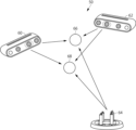
図1に、この発明の第1の実施の形態に係る校正装置を用いるセンサシステム50の概略構成を示す。図1を参照して、このセンサシステム50は、2台のRGB-Dセンサ60及び62と、1台のマイクロホン・アレイ64を含み、2人の対象人物66及び68の位置を検出し、時系列の位置データを出力する。RGB-Dセンサ60及びびRGB-Dセンサ62はRGB画像とセンサから対象までの距離を測定可能なセンサであり、各センサが検出した対象人物66及び68の3次元座標を、各センサの位置を原点とする各センサのローカル座標で出力する。またマイクロホン・アレイ64は2次元センサであり、マイクロホン・アレイ64が得た対象人物66及び68の二次元座標をマイクロホン・アレイ64の位置を原点とするローカル座標で出力する。なお、マイクロホン・アレイは人物が発話したときしか人物の位置を検出できない。したがって、マイクロホン・アレイを含むセンサシステムのための後述する訓練データの収集及び校正用データの収集では、所定領域内で人物が歩き回る際に何らかの発話を行う必要がある。
1.
各ローカルセンサの位置及び姿勢(向き)が正確に分かっていれば、各センサが検出した人物のグローバル座標及びそれらの対応関係も分かる。したがってこれらセンサの出力を組合せてこれらセンサが置かれた視聴覚環境をコンピュータで容易に管理できる。 If the position and orientation (direction) of each local sensor are precisely known, then the global coordinates of the people detected by each sensor and their correspondences can also be determined. Therefore, by combining the outputs of these sensors, the audiovisual environment in which these sensors are placed can be easily managed by computer.
しかし、これらセンサの位置又は姿勢が分からない場合には、各センサの出力する座標値を共通のグローバル座標に変換できるように各センサの出力を校正する必要がある。 However, if the positions or orientations of these sensors are unknown, it is necessary to calibrate the output of each sensor so that the coordinate values output by each sensor can be converted to common global coordinates.
(2)センサの校正
図2を参照して、例えばグローバル座標としてRGB-Dセンサ60のローカル座標80を採用するものとする。この場合、原点がローカル座標82により表されるようにローカル座標80の原点と一致するようにRGB-Dセンサ62のローカル座標を平行移動する。さらにローカル座標82の各軸(e1’、 e2’及びe3’の単位ベクトルで表される。)をRGB-Dセンサ60のローカル座標80の各軸(e1、 e2及び3の単位ベクトルで表される。)と一致するようにローカル座標を回転する。この際の並行移動による座標変換をt2、回転による座標変換をR2と表せば、RGB-Dセンサ62のローカル座標をRGB-Dセンサ60のローカル座標80によるローカル座標に変換する変換は通常は以下の式で表される。
(2) Calibration of the Sensor With reference to FIG. 2, for example,

同じ人物に関し、m+1回のタイムステップでRGB-Dセンサ60及び62が観測した3次元のセンサ出力ベクトルをそれぞれp1
i及びp2
i(i=0,1,…,m)とする。すると、上式の行列R2及びベクトルt2はそれぞれ、以下の式により求められる。
For the same person, the three-dimensional sensor output vectors observed by the RGB-

一方、RGB-Dセンサ60とマイクロホン・アレイ64との間の校正は以下のようにして行える。マイクロホン・アレイ64では対象までの距離は測定できず、方向が分かるだけである。そこでこのようにRGB-Dセンサ60とマイクロホン・アレイ64との校正は3D+2D校正と呼ぶ。
On the other hand, calibration between the RGB-
ある同一の人物に対するマイクロホン・アレイ64の出力をp3、RGB-Dセンサ60の出力をp1とする。これはそれぞれ以下のように表せる。
The output of the

マイクロホン・アレイ64のローカル座標p3からRGB-Dセンサ60のローカル座標(すなわちグローバル座標)への変換は、上記した特殊直交群SO(3)に関連するリー代数so(3)におけるマイクロホン・アレイ64の姿勢を表す行列ξを用いて、以下の式により容易に算出できる。
Transformation from the local coordinates p3 of the


こうしてξ3を求めることにより、マイクロホン・アレイ64のローカル座標で得られる測定データを、RGB-Dセンサ60のローカル座標(すなわちグローバル座標)に変換できる。
By determining ξ 3 in this manner, the measurement data obtained in the local coordinates of the
(3)因子グラフ
上記した校正は、各センサが測定した人物の対応付けができていることが前提である。しかし、現実の環境では、測定誤差があるために、例えば複数の人物の位置を複数のセンサで測定したときに、各センサの出力のどの人物が互いに対応するかを正確に知ることが難しいという問題がある。
(3) Factor Graph The above calibration is based on the premise that the people measured by each sensor are associated with each other. However, in a real environment, due to measurement errors, it is difficult to know exactly which people correspond to which sensor outputs when the positions of multiple people are measured by multiple sensors.
そこで、そのようなノイズを含むデータから確率的な表現を推定することが考えられる。そのような推定問題に適したツールとして因子グラフがある。因子グラフは、ベイジアンネットワークと同様、同時確率を因子の積で表すことができる。 One solution is to estimate probabilistic expressions from such noisy data. Factor graphs are a suitable tool for such estimation problems. Like Bayesian networks, factor graphs can express joint probabilities as products of factors.
図3に例としてグラフ100を示す。図3において、S1及びS2はセンサ、x1i及びy1i(i=1、2)はセンサS1が2回にわたり測定した第1の人物及び第2の人物の位置データ、x2i及びy2i(i=1、2)はセンサS2がセンサS1と同時に2回にわたり測定した第1の人物及び第2の人物の位置データをそれぞれ示す。なお添字iはタイムステップを示す。xは第1の人物の位置データを、yは第2の人物の位置データを、それぞれ示す。
これらは、図3に示すように、センサS1及びS2、センサS1の測定した位置データx1i及びy1i(i=1、2)、並びにセンサS2の測定した位置データx2i及びy2i(i=1、2)を頂点とし、各センサとそのセンサの測定した位置データのうち同じタイムステップで測定された位置データに対応する頂点の全ての組合せを結ぶエッジとからなるグラフ100を形成する。
As shown in FIG. 3, these form a
図3に示すように、同じ人物に対してセンサS1及びS2が測定した位置は、測定誤差のために一般的には互いに異なる値となり、直ちには互いに対応付けることができない。この実施の形態では、グラフ100を用いて以下のような考え方で測定データの対応付けを行う。
As shown in Fig. 3, the positions measured by the sensors S1 and S2 for the same person generally have different values due to measurement errors, and cannot be immediately associated with each other. In this embodiment, the measurement data is associated with each other using a
すなわち、図4を参照して、x11とx21,y11とy21、x12とx22,及びy12とy22とが同一人物を表す場合、グラフ100においてこれらを結ぶエッジ120、122、124及び126のみを残し、他のエッジ(点線で表される)を全て削除するように因子グラフ100を変形できれば、センサS1の測定データとセンサS2の測定データとの対応付けを行うことができる。
That is, referring to FIG. 4, in the case where x11 and x21 , y11 and y21 , x12 and x22 , and y12 and y22 represent the same person, if the
この実施の形態では、この対応付けのためにグラフ・ニューラル・ネットワーク(GNN)を用いる。GNNは、ニューラル・ネットワークの一種であって、グラフ構造を持つデータを処理するのに適している。最近になって、推論及びマルチ・エージェント対話型システムにGNNが非常に有効であることがわかってきた。非特許文献3では、対比較を行うためのグラフにおけるローカルなメッセージ伝達に関してGNNが用いられている。以下に説明するこの発明の第1の実施の形態に係るシステムは、非特許文献3の記載をヒントに、GNNを用いて2つのセンサの測定した人物の一致を推定する。この詳細については後述する。 In this embodiment, a graph neural network (GNN) is used for this matching. A GNN is a type of neural network that is suitable for processing data with a graph structure. Recently, GNNs have been found to be very effective in inference and multi-agent interactive systems. In Non-Patent Document 3, a GNN is used for local message transmission in a graph for pairwise comparison. The system according to the first embodiment of the present invention described below takes inspiration from the description in Non-Patent Document 3 and uses a GNN to estimate the match between people measured by two sensors. Details of this will be described later.
以下に説明する実施の形態では、2つの時系列データが同一の人物のものか否かを判定するためのニューラル・ネットワークを用いる。2つの時系列データは、複数のセンサが所定のタイムステップにわたり出力する、第1及び2の位置データからなる2つの時系列データである。このニューラル・ネットワークを用いることで、例えば2人の人物について第1のセンサが出力する2つの時系列データと、同じ2人の人物について第2のセンサが出力する2つの時系列とを比較し、第1のセンサのどの時系列データと、第2のセンサのどの時系列データとが同じ人物を表すか、その対応付けを行う。そのために上記した非特許文献3の記載をヒントに、上記した機能を提供するようにニューラル・ネットワークの訓練を行う。 In the embodiment described below, a neural network is used to determine whether two pieces of time series data are from the same person. The two pieces of time series data are two pieces of time series data consisting of first and second position data output from multiple sensors over a predetermined time step. By using this neural network, for example, two pieces of time series data output from a first sensor for two people are compared with two pieces of time series output from a second sensor for the same two people, and which pieces of time series data from the first sensor and which pieces of time series data from the second sensor represent the same person are associated with each other. To this end, the neural network is trained to provide the above-mentioned functions, taking inspiration from the description in the above-mentioned non-patent document 3.
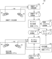
(4)システムの全体構成
図5は、この発明の第1の実施の形態に係る校正システム150の全体構成を示す。図5を参照して、校正システム150は、上記したニューラル・ネットワークを一部に含みそのニューラル・ネットワークの訓練を行うためのオートエンコーダ178と、オートエンコーダ178により訓練されたニューラル・ネットワークのパラメータを記憶するためのパラメータ記憶部180とを含む。以下、このニューラル・ネットワークをエンコーダと呼ぶ。
(4) Overall Configuration of the System Fig. 5 shows the overall configuration of a
校正システム150はさらに、エンコーダの訓練を行うための訓練データを生成するための訓練データ生成部160と、訓練データ生成部160により生成された訓練データを収集するための訓練データ収集装置170と、訓練データ収集装置170により収集された訓練データをコンピュータ可読な形式で記憶するための訓練データ記憶部172と、上記したエンコーダの訓練を行うためのコンピュータ・プログラムを記憶するための訓練プログラム記憶部176と、訓練プログラム記憶部176に記憶されたプログラムを実行し、訓練データ記憶部172に記憶された訓練データを用いてオートエンコーダ178の訓練を行い、それによってオートエンコーダ178の一部であるエンコーダの訓練を行うためのオンライン校正装置訓練システム174と、訓練が終了した後の、オートエンコーダ178をコンピュータにより実現するためのパラメータを記憶するためのパラメータ記憶部180とを含む。
The
この例では、訓練データ生成部160はRGB-Dセンサ60及び62を含み、所定領域内を移動する2人の人物の位置データの、所定のタイムステップごとに計測した所定タイムステップ数の時系列を生成するものとする。もちろん、訓練では、このような訓練データを幾通りも生成し訓練データ記憶部172に記憶しておく。
In this example, the training
校正システム150はさらに、校正対象となる校正対象音響処理システム162を含む。この実施の形態では、校正対象音響処理システム162は訓練データ生成部160と同様、RGB-Dセンサ60及び62を含み、所定領域を移動する2人の人物の位置データの時系列を取得するものとする。またこの例ではRGB-Dセンサ60及び62の位置及び姿勢に関する校正を行うことが目的である。したがって校正前にRGB-Dセンサ60及び62の位置及び姿勢を厳密に設定する必要はない。
The
校正システム150はさらに、パラメータ記憶部180に記憶されたパラメータのうち、エンコーダに関するパラメータと、オートエンコーダ176に記憶された、エンコーダのアルゴリズムを実現するプログラムとを用いて、校正対象音響処理システム162から得られる所定のタイムステップ数の時系列の位置データを処理し、RGB-Dセンサ60とRGB-Dセンサ62との間の校正を行うためのオンライン校正装置182と、オンライン校正装置182による校正の結果得られた校正パラメータを記憶するための校正パラメータ記憶部186とを含む。この実施の形態では、RGB-Dセンサ60のローカル座標をワールド座標とし、RGB-Dセンサ62のローカル座標をワールド座標に変換するためのパラメータ(前述の行列R2及びベクトルt2)がオンライン校正装置182により求められ、校正パラメータ記憶部186に記憶される。
The
校正システム150はさらに、オンライン校正装置182による校正時、及び校正対象音響処理システム162の実際の稼働時に得られる時系列データを用いてエンコーダの訓練を同時並行的に行うための校正装置バックグラウンド更新システム184を含む。
The
(5)コンピュータによる実現
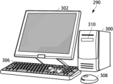
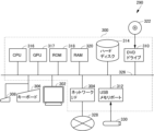
図5において、訓練データ生成部160及び校正対象音響処理システム162を除く各機能部は、コンピュータハードウェア及びその上で実行されるコンピュータ・プログラムにより実現される。図6にそうしたコンピュータシステム290の外観を示し、図7にコンピュータシステム290のハードウェア構成をブロック図で示す。
(5) Implementation by a Computer In Fig. 5, each functional unit except for the training
図6を参照して、このコンピュータシステム290は、DVDドライブ310を有するコンピュータ300と、キーボード306と、マウス308と、モニタ302とを含む。
Referring to FIG. 6, the
図7を参照して、コンピュータ300は、DVDドライブ310に加えて、CPU316と、CPU316、DVDドライブ310に接続されたバス326と、ニューラル・ネットワークの学習及び推論の際の数値計算を高速に行うためのGPU317と、コンピュータ290のためのブートアッププログラム等を記憶するROM318と、バス326に接続され、実行対象のプログラム命令、システムプログラム、およびプログラム実行中の作業データ等を記憶するROM318と、不揮発性メモリであるハードディスク314を含む。コンピュータシステム290はさらに、他端末との通信を可能とするネットワーク328への接続を提供するネットワークI/F304と、USBメモリ330が装着可能でコンピュータ290の各部とUSBメモリ330との間のデータ交換を可能にするUSBメモリポート312とを含む。GPU317は計算を高速にするためのもので、機能的には必須のものではなくCPU316で代行できる。しかし計算を高速にするためにはGPU317があることが望ましい。
7, in addition to the
本実施の形態では、図5に示す訓練データ記憶部172、オートエンコーダ176、パラメータ記憶部180及び校正パラメータ記憶部186等は、いずれもハードディスク314又はRAM320により実現される。
In this embodiment, the training
コンピュータシステム290に校正システム150及びその構成要素の機能を実現させるためのコンピュータ・プログラムは、DVDドライブ310に装着されるDVD322又はUSBメモリ330に記憶され、DVDドライブ310又はUSBメモリポート312からハードディスク314に転送される。又は、プログラムはネットワーク328を通じてコンピュータ300に送信されハードディスク314に記憶されてもよい。プログラムは実行の際にRAM320にロードされる。DVD322から、又はネットワークを介して、直接にRAM320にプログラムをロードしてもよい。
A computer program for causing the
このプログラムは、コンピュータ300にこの実施の形態の校正システム150の訓練データ収集装置170、オンライン校正装置訓練システム174、オートエンコーダ178、オンライン校正装置182及び校正装置バックグラウンド更新システム184として動作を行なわせる複数の命令を含む。この動作を行なわせるのに必要な基本的機能のいくつかはコンピュータ300上で動作するオペレーティングシステム(OS)若しくはサードパーティのプログラム、又はコンピュータ300にインストールされる各種プログラミング・ツール・キットのモジュールにより提供される。したがって、このプログラムはこの実施の形態のシステムおよび方法を実現するのに必要な機能全てを必ずしも含まなくてよい。このプログラムは、命令のうち、所望の結果が得られるように制御されたやり方で適切な機能又は所望のプログラミング・ツールを呼出すことにより、上記した校正システム150及びその構成要素としての動作を実行する命令のみを含んでいればよい。もちろん、プログラムはコンピュータ290に所望の機能を実現させるための命令を全て含んでもよい。コンピュータシステム290の動作は周知であるので、ここでは繰返さない。
This program includes a number of instructions that cause the
なお、このプログラムはCPU316が直ちに実行可能ないわゆるオブジェクトプログラムでもよいし、インタープリタにより逐次実行可能な形式に変換することが必要なスクリプト形式でもよい。
This program may be a so-called object program that can be executed immediately by the
(6)オートエンコーダ
図8は、図5に示すオートエンコーダ178の概略構成を示す。図8を参照して、このオートエンコーダ178は、2つの頂点の一定数のタイムステップの位置データの時系列を入力とし、その2つの頂点の間にエッジがあるか否かに関する確率分布354(p(e|ν)、ただしνは2つの頂点の位置データの時系列、eはその2つの頂点の間にエッジがあるか否かを示す値)にしたがった値を出力するエンコーダ350と、異なる頂点の組合せからの位置データの入力に応答してエンコーダ350が出力する、確率分布354にしたがった値のうち、最も大きなものに対応する頂点の組合せの、特定のタイムステップにおける位置データを入力として、出力がその入力と等しくなるように訓練されるニューラル・ネットワークからなるデコーダ352とを含む。したがってデコーダ352の出力するベクトルの次元数は入力ベクトルの次元数と同じである。オンライン校正装置訓練システム174は、エンコーダ350に可能な頂点の組合せの位置データの時系列を与え、エンコーダ350の出力である確率分布354のサンプリング値が最も大きな組合せの、特定時点での位置データをデコーダ352に与え、デコーダ352の出力がそのデコーダ352への入力と等しくなる方向に近づくように、エンコーダ350及びデコーダ352のパラメータを調整する動作を、位置データの時系列の先頭から順番に最後まで行う処理を所定の終了条件が成立するまで繰返してオートエンコーダ178の訓練を行う。この実施の形態では、終了条件は上記繰返しを予め定められた回数だけ行ったときに充足される。
(6) Autoencoder Fig. 8 shows a schematic configuration of the
(7)エンコーダの訓練
エンコーダ350は、上記非特許文献3に記載された、グラフの頂点からエッジへ、さらにエッジから頂点へのメッセージ伝達を行うニューラル・ネットワークをヒントにしたものである。図9に、非特許文献3に記載されたニューラル・ネットワークの構成の概略を示す。
(7) Encoder Training The
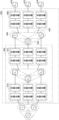
図9を参照して、このメッセージ伝達ニューラル・ネットワーク400は、2つの頂点の組合せ390、392、及び組合せ394を別々の入力として、それぞれの組合せを構成する頂点の間にエッジがあるか否かを示す値e1,2,e1,3及びe2,3を出力するための全結合層からなる第1段のニューラル・ネットワーク410と、ニューラル・ネットワーク410の値のうち2つの値からなる全ての組合せ420、422及び424を入力として受け、ニューラル・ネットワーク410に入力された3つの頂点に対応する値440、442及び444を出力するように訓練される第2段のニューラル・ネットワーク412とを含む。ニューラル・ネットワーク410及び412は、この実施の形態ではいずれも全結合層からなる。
9, this message-passing
この実施の形態では、図9に示される構成を基礎に、さらに図10に示す構成を持つエンコーダ350をオートエンコーダ178の前段に用いる。図10を参照して、エンコーダ350は、図9に示すメッセージ伝達ニューラル・ネットワーク400と、メッセージ伝達ニューラル・ネットワーク400が頂点の3つの組合せが入力されたことに応答してそれぞれ出力する値440、442及び444からの2つを組合せた組合せ450、452、及び組合せ454を入力として、これら組合せに対応する頂点の間にエッジが存在する確率を示すスコアであるスコア470、472、及びスコア474をそれぞれ出力するためのデコーダ460とを含む。スコア470、472、及びスコア474はそれぞれ、頂点1及び2がエッジで結ばれている確率、頂点1及び3がエッジで結ばれている確率、及び頂点2及び3がエッジで結ばれている確率を示す値であり、デコーダ460はそのような値を出力するように訓練される。デコーダ460も含めたエンコーダ350は、図8に示すオンライン校正装置訓練システム174により、オートエンコーダ178の全体を対象におこなわれる訓練により訓練される。
In this embodiment, an
図11に、オートエンコーダ178の訓練を行うようコンピュータシステム290を機能させるためのコンピュータ・プログラムの制御構造をフローチャート形式で示す。図11を参照して、このプログラムは、ステップ500により実行を開始する。ステップ500では、校正の対象となるセンサの位置及び姿勢がいずれも乱数により初期化される。ステップ500ではこの他にも、エンコーダ350及びデコーダ352のパラメータの初期化も行われる。この初期化は、乱数により行ってもよいし、所定の事前学習により定められた値を各パラメータに代入して行ってもよい。他のシステムで訓練済の値を各パラメータに代入してもよい。
Figure 11 shows, in the form of a flowchart, the control structure of a computer program for causing the
このプログラムはさらに、図5に示す訓練データ記憶部172に記憶されている、予め訓練データ収集装置170により収集した訓練データを訓練データ記憶部172から読出し、図7に示すRAM320にロードするステップ502を含む。訓練データの収集では、図5に示す訓練データ生成部160にRGB-Dセンサ60及び62を設置し、所定領域を所定人数(この実施の形態では2人)が移動する状態で、所定の時間間隔(タイムステップ)で、所定の時間(所定数のタイムステップ)にわたりそれらの人の位置及び速度を時系列データとして訓練データ収集装置170が収集し、訓練データ記憶部172に格納する。こうした作業を様々な状況で繰返し行い、多くの訓練データの組を収集することが必要である。
This program further includes
このプログラムはさらに、ステップ502に続き、全訓練データ中の訓練データの組の全てに対して処理506を所定の回数だけ繰返すことによりオートエンコーダ178の訓練を行うステップ504と、ステップ504により訓練されたオートエンコーダ178のパラメータを図7に示すハードディスク314等の不揮発性記憶装置に記憶してプログラムの実行を終了するステップ508とを含む。
Following
ここで言う訓練データの組とは、2人の人物に対し訓練データ生成部160が1回の訓練データ収集のセッションで収集した位置データの時系列の組のことをいう。ここで「セッション」とは、所定のタイムステップ数の測定データの集まりのことをいう。
The training data set referred to here is a set of time series of position data collected by the training
各タイムステップの測定データは、各センサについて、そのセンサが2人の人物について測定した位置データを含む。各位置データは3次元の座標データ及びその差分(速度)データを含む。すなわち、あるタイムステップでのセンサ出力である位置データは6次元である。したがって、あるタイムステップでの、2人の人物に対し2個のセンサから得られる測定データは2×2×6個の座標値を含む。この座標値は、各センサを原点とするローカル座標で与えられる。これらが各タイムステップで得られるので、結果として、1セッションの測定データは、第1のセンサが出力する2人の位置データからなる2つの時系列データと、第2のセンサが出力する2人の位置データからなる2つの時系列データとを含む。これら4つの位置データの時系列データの集合をここでは時系列データの「組」と呼ぶ。 The measurement data for each time step includes, for each sensor, position data measured by that sensor for two people. Each position data includes three-dimensional coordinate data and its difference (velocity) data. In other words, the position data that is the sensor output at a certain time step is six-dimensional. Therefore, the measurement data obtained from two sensors for two people at a certain time step includes 2 x 2 x 6 coordinate values. These coordinate values are given in local coordinates with each sensor as the origin. Since these are obtained at each time step, the measurement data for one session includes two time series data consisting of the position data of the two people output by the first sensor, and two time series data consisting of the position data of the two people output by the second sensor. Here, a collection of time series data of these four position data is called a "set" of time series data.
この時系列データの構成を表形式で示せば以下のとおりである。

この表から分かるように、各センサが各人物について1タイムステップで出力する位置データは6次元(位置+速度)である。1回のセッションでN回のタイムステップの測定をするとすれば、1つのセンサが1人の人物に対して出力する位置データの時系列は、それぞれ6(位置+速度)次元のベクトル×N個の系列となる。これは6×N次元ベクトルということもできる。測定対象の人物が2人であり、センサは2つあるので、全体として1セッションの訓練データは4個の6×N次元ベクトルである。この4個の6×N次元ベクトルの全体が前述した「組」を構成し、6×N次元ベクトルの各々が前述した時系列データである。 As can be seen from this table, the position data that each sensor outputs for each person in one time step is six-dimensional (position + velocity). If N time steps are measured in one session, the time series of position data output by one sensor for one person will be a series of N vectors with 6 (position + velocity) dimensions. This can also be called a 6 x N-dimensional vector. As there are two people being measured and two sensors, the training data for one session as a whole is four 6 x N-dimensional vectors. These four 6 x N-dimensional vectors together make up the "set" mentioned above, and each of the 6 x N-dimensional vectors is the time series data mentioned above.
処理506は、訓練データの各組に対し、その先頭から以下のステップ512を繰返すステップ510を含む。
ステップ510は、処理対象の組内で可能なペアの各々に対し、処理522を実行するステップ520と、ステップ520の結果、エンコーダ350からペアの数だけサンプリングされる値を比較し、最も高い値のペアの訓練データのうち、ステップ510で指定される順番の訓練データを選択してデコーダ352に入力するステップ524と、ステップ524での入力に応答してデコーダ352の出力を算出するステップ526と、デコーダ352への入力とその出力との誤差を用いた誤差逆伝播法により、オートエンコーダ178の全パラメータを調整してステップ512を終了するステップ528とを含む。
Step 510 includes
処理522は、その組で、ステップ520により指定されたペアに対応する全訓練データをエンコーダ350に入力するステップ540と、入力に応答してエンコーダ350が出力する値をサンプリングして処理522を終了するステップ542とを含む。サンプリングされた値は、例えば図7に示すRAM320に一時的に保持される。
図11に示す処理を実行することで図8に示すオートエンコーダ178が訓練され、したがってその一部であるエンコーダ350も訓練される。
By executing the process shown in FIG. 11, the
(8)校正
上記したように訓練されたオートエンコーダ178のうち、エンコーダ350を用いて図5の校正対象音響処理システム162の校正が行われる。図5には2台のRGB-Dセンサ60及び62のみが示されている。しかし実際には、校正対象音響処理システム162には3台以上のセンサが校正対象音響処理システム162には設けられていることが多い。また各センサはRGB-Dセンサ60のような3次元センサには限らず、マイクロホン・アレイであってもよい。いずれかのセンサのローカル座標をグローバル座標として選択すれば、どのセンサも、グローバル座標に対応するセンサとの対でその位置を校正すればよい。グローバル座標として選択されたセンサをここでは基準センサと呼ぶ。
(8) Calibration Among the
図6及び図7に示すコンピュータシステム290を図5に示すオンライン校正装置182として機能させるプログラムの制御構造を図12にフローチャート形式で示す。図12を参照して、このプログラムは、初期処理を実行するステップ560を含む。この初期処理では、各センサの位置座標及びその姿勢を乱数により初期化する。他に、処理に必要な記憶領域を図7に示すRAM320に確保する処理等もこのステップ560で実行される。
FIG. 12 shows in the form of a flowchart the control structure of a program that causes the
このプログラムはさらに、図5に示す校正対象音響処理システム162内を所定人数(この実施の形態では2人)の人物に移動してもらい、各センサから校正用データを収集するステップ562を含む。各校正用データはエンコーダ350の訓練時と同じであることを想定する。訓練時の各訓練データのタイムステップがm+1であるとすれば、ステップ562で収集する校正用データもm+1タイムステップである。また校正用データはセンサ個数だけ得られる。
This program further includes
このプログラムはさらに、後述の処理566を基準センサ以外のセンサ数だけ繰返すことにより、各センサの校正を行い、校正パラメータをRAM320等に保存するステップ564を含む。
The program further includes
処理566は、処理対象の校正用データのうち、可能なデータのペアの数だけ、以下のステップ582を繰返して実行するステップ580と、ステップ580による処理の結果、各データペアに対してエンコーダ350から出力される値を比較し、各データペアが同一の人物を指すか否かを判定し、その結果にしたがってデータの対応付けを行う(人物の同定を行う)ステップ584と、センサの種類にしたがった式を用いて対象センサ(基準センサ以外のセンサ)の位置及び姿勢の校正パラメータを算出するステップ586と、ステップ586で算出された校正パラメータをRAM320等に保存して処理566を終了するステップ588とを含む。
ステップ582は、エンコーダ350に処理対象のペアの校正用データを全て入力するステップ600と、ステップ600で与えられた入力に応答してエンコーダ350が出力する値をRAM320等に一時的に保存してステップ582を終了するステップ602とを含む。
Step 582 includes
この処理をコンピュータシステム290が実行することにより、校正対象音響処理システム162内の各センサの校正が行われる。この処理で得られた校正パラメータを用いて各センサの位置及び姿勢を基準センサのローカル座標(グローバル座標)に変換することで各人物の位置を定めることができる。
This process is executed by the
なお、ステップ586で使用される校正パラメータの算出式は、RGB-Dセンサのような3次元センサと、マイクロホン・アレイのような2次元センサとの場合で異なっている。この式については前述したとおりである。
The formula for calculating the calibration parameters used in
(9)校正との並行訓練
この実施の形態ではさらに、上記したように校正パラメータを決定した後にも、各センサが出力するデータを用いて校正パラメータの更新を行う。コンピュータシステム290をそのための校正装置バックグラウンド更新システム184として機能させるプログラムの制御構造を図13に示す。
(9) Parallel Training with Calibration In this embodiment, even after the calibration parameters are determined as described above, the calibration parameters are updated using the data output by each sensor. The control structure of a program that causes the
図13を参照して、このプログラムは、初期処理を行うステップ620と、後述する処理624を終了条件が成立するまで繰返すことで、各センサの校正パラメータを更新した値を算出するステップ622と、ステップ622で各センサに対して算出された更新後の校正パラメータで、図5の校正パラメータ記憶部186に記憶された校正パラメータを更新するステップ626とを含む。
Referring to FIG. 13, this program includes
ステップ620では、処理に必要な記憶領域をRAM320に確保する処理、及び図5に示す校正パラメータ記憶部186に記憶された各センサの校正パラメータをRAM320に読み出す処理等が行われる。
In
処理624は、訓練データ及び校正用データと同様の、所定のタイムステップ数の更新用データを更新対象の各センサから受信するステップ640と、後述の処理644を所定の回数繰返すステップ642とを含む。
処理644は、更新用データの各組に対して、その時系列の先頭から順に以下の処理662を実行するステップ660を含む。
処理662は、処理対象の組のデータの中で可能な各データペアに対して処理682を実行することにより、各データペアについて、当該データベアに関する全更新用データが入力されたときのエンコーダ350の出力をサンプリングするステップ680と、ステップ680のサンプリング結果にしたがって、デコーダ入力の時系列データのペアを選択し、そのペアの、ステップ660で指定される順番のデータをデコーダ352に入力するステップ684と、ステップ684に続き、デコーダ352の出力を算出するステップ686と、デコーダ352への入力とステップ686で得られたデコーダ352の出力との誤差を用いた誤差逆伝播法により、オートエンコーダ178のパラメータを調整するステップ688とを含む。
処理682は、処理中の組の処理中のペアの全更新用データをエンコーダ350に入力するステップ700と、ステップ700での入力に対するエンコーダ350の出力をサンプリングするステップ702とを含む。
この処理は各センサ出力による人物の位置の検出と並行してバックグラウンドで動作可能である。したがって、図13に示すプログラムをコンピュータシステム290が実行することにより、コンピュータシステム290は図5に示す校正装置バックグラウンド更新システム184として機能する。
This process can run in the background in parallel with the detection of the position of a person using the output of each sensor. Therefore, when the
2 動作
上記した構成を持つ校正システム150は以下のように動作する。
2. Operation The
(1)動作全体の流れ
校正システム150の全体の動作の流れは以下のとおりである。
(1) Overall Operation Flow The overall operation flow of the
・訓練データ生成部160にRGB-Dセンサ60、62等のセンサを配置する。
・訓練データ収集装置170が訓練データを収集し訓練データ記憶部172に格納する。
・オンライン校正装置訓練システム174が訓練データ記憶部172とオートエンコーダ176とを用いてオートエンコーダ178を訓練する。訓練後のオートエンコーダ178のパラメータはパラメータ記憶部180に記憶される。
Sensors such as RGB-
The training
An online
・校正対象音響処理システム162にRGB-Dセンサ60、62等のセンサを配置する。
・RGB-Dセンサ60、62等が検出対象とする領域内を2人の人物が歩き回り、その間にオンライン校正装置182が校正用データを収集する。
・オンライン校正装置182がパラメータ記憶部180からオートエンコーダ178のパラメータを読み込み、エンコーダ350及びデコーダ352を構築する。
・オンライン校正装置182が校正用データに対して図12に示す処理を実行することで各センサの校正パラメータを算出する。校正パラメータは校正パラメータ記憶部186に記憶される。
Place sensors such as RGB-
Two people walk around within the area that is the detection target of the RGB-
The
The
・その後、校正パラメータ記憶部186に記憶された校正パラメータを用いて、図示しない音源定位装置等が所定領域内の人物の位置を検出する処理を実行する。
・人物の位置の検出と並行して、その際に得られた時系列データを用い、バックグラウンドでコンピュータシステム290がオートエンコーダ178の訓練を行う。その結果、エンコーダ350を含むオートエンコーダ178が新たなデータに基づいて更新される。
After that, using the calibration parameters stored in the calibration
In parallel with the detection of the person's position, the
(2)エンコーダ350の訓練
エンコーダ350の訓練は以下のようにして実行される。図5を参照して、RGB-Dセンサ60、62等が配置された領域内を二人の人物が歩き回り、そのあいだのセンサ出力を訓練データ収集装置170が収集する。これがオートエンコーダ178の訓練データとして訓練データ記憶部172に記憶される。必要な量の訓練データが収集できたらオートエンコーダ178の訓練を行う。
(2) Training of the
図11を参照して、ステップ500では、校正の対象となるセンサの位置及び姿勢がいずれも乱数により初期化される。ステップ500ではこの他にも、エンコーダ350及びデコーダ352のパラメータの初期化も行われる。この初期化は、乱数により行ってもよいし、所定の事前学習により定められた値を各パラメータに代入してもよい。他のシステムで訓練済の値を各パラメータに代入してもよい。
Referring to FIG. 11, in
さらにステップ502では、コンピュータシステム290は訓練データを訓練データ記憶部172から読出し、図7に示すRAM320にロードする。前述したように、この訓練データは複数のセッションにより得られた訓練データの組を含む。各組は4つの訓練データの時系列を含む。タイムステップ単位でいえば、各タイムステップの訓練データは、4つの6次元ベクトルを含む。2つのセンサが2人の人物についてそれぞれ6次元(位置+速度)ベクトルを出力するためである。
Furthermore, in
さらに、ステップ502に続き、ステップ504において、全訓練データ中の訓練データの組の全てに対して処理506を所定の回数だけ繰返すことによりオートエンコーダ178の訓練を行う。
Further, following
ステップ508では、ステップ504により訓練されたオートエンコーダ178のパラメータを図7に示すハードディスク314等の不揮発性記憶装置に記憶してプログラムの実行を終了する。
In
処理506ではまず、訓練データに含まれる各組に対し、先頭のタイムステップの測定データを選択し(ステップ510)、その組で可能なデータのペアの各々に対して処理522を行う。その組で可能なデータのペアとは、第1のセンサの第1及び2の人物の測定データと、第2のセンサの第1及び2の人物の測定データとの間で可能なペアのことをいう。図3を例に説明すると、先頭のタイムステップでの測定データはx11、y11、x21及びy21、第2のタイムステップでの測定データはx12、y12、x22及びy22である。これらのうち、x11及び12が第1の時系列データを形成する。この時系列データをx1とする。同様に、x21及び22が時系列データx2を、y11及び12が時系列データy1を、y21及び22が時系列データy2を、それぞれ形成する。これらの間での可能な組合せは、センサS1で観測された時系列データx1及びy1のうちの一つと、センサS2で観測された時系列データx2及びy2のうちの一つとの組合せとなる。すなわち可能な組合せは(x1、2)、(x1、y2)、(y1、x2)、及び(y1、2)の4通りである。これらは図3で測定データを結ぶエッジとして表現されている。
In the
ステップ520では、この4通りの組合せの全てに対し、処理522を実行する。処理522のステップ540では、例えば(x1、2)の組合せについて、時系列データx1を構成する全ての訓練データx11及び12と、時系列データx2を構成する全ての訓練データx21及び22とが連結されたベクトルがエンコーダ350に入力される。この入力に応答して、エンコーダ350がその内部のパラメータにより定まる演算を行い、結果として一つの値を出力する。この値は、ステップ542でエンコーダ350の規定する確率分布354からサンプリングしたものであり、時系列データx1と、時系列データx2とが同一の人物の位置を測定したものか否かを示すスコアである。もちろん、訓練の開始時にはエンコーダ350は正しい予測を行えるような状態にはなっていないので、このスコアは信頼がおけない。しかし、処理506を繰返し実行することにより、エンコーダ350のパラメータの訓練が行われ、入力された時系列のペアが同じ人物に関する測定データか否かを示すスコアを高い精度で出力できるようになる。
In
このスコアを(x1、2)の組合せに対応する値としてRAM320に一旦記憶する。同様に、他の(x1、y2)、(y1、x2)、及び(y1、2)の3通りについても処理522を実行し、ステップ542で得られた値をRAM320に記憶する。
This score is temporarily stored in
ステップ520の処理が完了したところで、ステップ524において、上記した4つの組合せについて得られたスコアが最も高いものを選択し、その時系列データの中で、ステップ510により指定された順番の測定データを組合せたものをデコーダ352に入力する。例えば(x1、y2)のスコアが最も高かった場合には、x11及びy21を連結したベクトルをデコーダ352に入力する。
When the process of
ステップ526では、デコーダ352のパラメータにしたがい、入力されたベクトルに対するデコーダ352の出力を算出する。
In
ステップ528では、デコーダ352に入力されたベクトル(現在の例ではx11及びy21を連結したベクトル)とデコーダ352が出力したベクトルとの誤差を用いた誤差逆伝播法により、オートエンコーダ178の全体の学習が行われる。
In
続いて次のステップ512の処理が次のタイムステップの測定データに対して行われる。この場合、ステップ520で行われる処理は先頭のタイムステップの測定データについて行われた処理と全く同じである。ただしエンコーダ350のパラメータは1回目の繰返しとは変化している。
Then, the
以下同様の処理が行われるが、ステップ524で選択されデコーダ352に入力されるのは、ステップ542でサンプリングされた値が最も大きな時系列データの、2番目の測定データのベクトルの組合せである。ステップ528の処理は1番目の測定データに対して行われたものと同様である。
The same process is carried out from here on, but what is selected in
このようにして、1個の測定データの組の全てのタイムステップについてステップ512の処理が実行されると、処理506の1回目の処理が完了する。この結果、オートエンコーダ178のパラメータはさらに変化する。ステップ504によれば、この処理をさらに何回か繰返す。この繰り返しによりオートエンコーダ178のパラメータの訓練が進行する。ここでは所定回数だけ処理506の処理を実行した時点でステップ504の終了条件が充足され、訓練を終了して処理はステップ508に進む。
In this way, when the process of
ステップ508では、ステップ504による繰返し処理で得られたオートエンコーダ178のパラメータをRAM320に保存し、さらにハードディスク314(図7)等からなるパラメータ記憶部180に転記することでオートエンコーダ178(及びエンコーダ350)の訓練が終了する。
In
(3)校正と並行訓練
上記した処理により訓練が終了したエンコーダ350を用いた校正対象音響処理システム162(図5)内の各センサの校正は以下のようにして行われる。
(3) Calibration and Parallel Training Calibration of each sensor in the sound processing system 162 (FIG. 5) to be calibrated using the
図12を参照して、ステップ560で初期処理が行われる。この実施の形態においては、この初期処理では、各センサの位置及び姿勢に関する値には乱数が設定される。またパラメータ記憶部180からエンコーダ350のパラメータを読み込むことでエンコーダ350を構築する。このエンコーダ350はオートエンコーダ178を用いて訓練されたものと同じアルゴリズムを提供するものである。
Referring to FIG. 12, in
ステップ562では、校正用データの組をセンサ個数だけ収集する。ここでは、校正用データのタイムステップ数はm+1であるものとする。はなお、この校正のための校正用データは、校正対象音響処理システム162の対象とする領域内を2人の人物が歩き回り、そのときの各センサの出力を得ることで収集される。
In
続いてステップ564では、基準となるセンサ以外のセンサの各々について処理566を繰返す。基準となるセンサとは、構成で説明したとおり、そのローカル座標をグローバル座標として扱うことが決められたセンサである。他のセンサのローカル座標の座標値をこのグローバル座標の座標値に換算するためのパラメータを得ることが校正処理の目的である。
Next, in
処理566では、処理対象のセンサと基準センサとの出力に含まれる時系列データについて、可能なペアの数だけステップ582を実行する。この処理は図11の処理522で実行される処理と同様であり、処理対象のデータが訓練データではなく校正用データである点のみが異なっている。
In
ステップ582の処理の結果、可能なペアの全てについてエンコーダ350の出力が得られる。その中で最も高い値が得られたペアの時系列同士が、同じ人物に関する位置データを示すものとして対応付けられる。この例では、残るペアの時系列同士が、もう一人の人物に関する位置データを示すものとして自動的に対応付けられる。
As a result of the processing of
ステップ586では、このようにして対応付けられた時系列同士を用い、校正対象となるセンサの種類に応じて、前記した式のいずれかを用いてその位置及び姿勢の校正パラメータが算出される。こうして算出された校正パラメータは、ステップ588で校正パラメータ記憶部186に記憶される。
In
処理566の処理を全ての対象センサに対して実行することで、基準となるセンサ以外の全てのセンサのローカル座標として得られた座標値を、グローバル座標の座標値に関するするための校正パラメータが校正パラメータ記憶部186に保存される。
By executing
この実施の形態ではさらに、上記したように校正パラメータを決定した後にも、各センサが出力するデータを用いてエンコーダ350のパラメータの更新を行う。コンピュータシステム290をそのための校正装置バックグラウンド更新システム184として機能させるプログラムの制御構造を図13に示す。
In this embodiment, even after the calibration parameters are determined as described above, the parameters of the
図13を参照して、このプログラムの実行が開始されると、ステップ620において初期処理を行う。ここでの初期処理は、オートエンコーダ178のパラメータをRAM320に読み込む処理、RAM320に作業用の記憶領域を確保する処理などを含む。
Referring to FIG. 13, when execution of this program starts, initial processing is performed in
続いてステップ622において、処理624を終了条件が成立するまで繰返す。この処理を終了するためには、操作者からの指示による場合、及び図示しない音源定位装置が動作を終了する場合等、任意の条件をトリガーにすることができる。
Next, in
処理624では、まず、図示しない音源定位装置等がセンサから収集した更新用データを受信する。この更新用データの1組は、訓練データと同様のタイムステップ数からなるものとする。
In
続いてステップ642において、ステップ640で受信した全ての更新用データに対して処理644を実行する。処理644の処理は訓練の処理とほぼ同様である。
Next, in
処理644では、更新用データに含まれる各組に対し、先頭のタイムステップのデータから順番に処理662を実行する。処理662の最初には、処理対象の組内の時系列データに対し、可能なペアの各々について処理682を実行する。処理682のステップ700ではその組のそのペアの全更新用データをエンコーダ350に入力する。続くステップ702において、エンコーダ350の出力をサンプリングし、RAM320に保持する。
In
ステップ680において処理682を全てのペアについて実行することで、処理対象の各組についてエンコーダ350の出力がサンプリングにより得られる。ステップ684ではこうしてサンプリングされた値の中で最も大きな値が得られたペアを選択し、そのペアの各タイムステップの測定データのうち、ステップ660により指定された順番の測定データからなるベクトルを連結したものをデコーダ352に入力する。続くステップ686で、デコーダ352の出力を算出する。ステップ688で、デコーダ352への入力とデコーダ352からの出力との誤差を用いて誤差逆伝播法により、パラメータ記憶部180に記憶されたオートエンコーダ178のパラメータを調整(更新)する。
In
そして所定の終了条件が成立するとこのプログラムは実行を終了する。このプログラムが実行されている間、オートエンコーダ178のパラメータはバックグラウンドで更新される。図示しない音源定位装置等はその動作にエンコーダ350は使用しないため、このようにオートエンコーダ178のパラメータを更新しても音源定位装置等の動作に影響は与えない。次回、オンライン校正装置182が校正処理を行うときのエンコーダ350の動作が変わってくることになる。
When a predetermined termination condition is met, this program ends its execution. While this program is being executed, the parameters of the
以上のようにこの実施の形態に係る校正システム150によれば、訓練データを自動的に生成した後、何ら人手を介さずに自動的にオートエンコーダ178(及びエンコーダ350)の訓練が行われる。また校正対象音響処理システム162が含むセンサの校正時にも、各センサの実際の位置及び姿勢を人手で設定することなく、単に所定領域内を2人の人物が歩いて校正用データを生成するだけで、各センサの校正パラメータを自動的に算出できる。またRGB-Dセンサ60のような3Dセンサだけではなくマイクロホン・アレイのような2Dセンサと3Dセンサとを組合せた音響処理システムでも校正パラメータを自動的に算出できるという効果がある。
As described above, according to the
3 実験
この第1の実施の形態に係るオートエンコーダ178による校正処理の性能をテストするために、以下に述べる実験を行った。実験では、非特許文献4で使用されたオープンデータセットを用いた。各カメラ測定値に、15cmの標準偏差のガウシアンノイズを加えた。マイクロホン・アレイの初期位置をランダムに設定し、そのマイクロホン・アレイに対するターゲット・アングルを、平均が0、標準偏差が2のガウシアンノイズにより生成した。
3 Experiments To test the performance of the calibration process by the
まず、オートエンコーダ178の訓練を行うために、5つの測定データの集合を準備した。各集合は100タイムステップの時系列データの組を含んでいた。 First, we prepared five sets of measurement data to train the autoencoder178. Each set contained a set of time series data with 100 time steps.
この実験により訓練したエンコーダ350を用いて人物の同定処理を行った結果、異なる人物について、それらが異なるとコンピュータ300が正しく判定した率は98.3%であった。このコンピュータ300を用いた校正を行った結果、得られた平均誤差はRGB-センサについては22mm、マイクロホン・アレイについては57mmであった。
When the
このようにこの第1の実施の形態によれば、手作業を介することなく、RGB-センサとマイクロホン・アレイの双方について、高い精度で校正を行うことができる。校正に要するエンコーダ350についても同様に人手を介することなく訓練できる。この訓練は教師なし学習であり、手作業で訓練データを準備する必要はない。訓練データの準備と校正処理とのいずれの場合も、単に所定領域を所定の人数の人間が歩き回り、さらにマイクロホン・アレイが対象に含まれる場合には適宜発話することが求められるだけである。
As described above, according to the first embodiment, both the RGB sensor and the microphone array can be calibrated with high accuracy without manual intervention. The
2.第2の実施の形態
1 構成
(1)全体構成
第2の実施の形態は、オンライン校正装置訓練システムに関する。図5に示すオンライン校正装置訓練システム174とは異なり、第2の実施の形態に係るオンライン校正装置訓練システムは、誤差逆伝播法によるオートエンコーダ178の訓練をミニバッチにより行う。
2.
(2)エンコーダの訓練
図14に、この第2の実施の形態においてオートエンコーダ178を訓練するためのプログラム(コンピュータシステム290をオンライン校正装置訓練システムとして機能させるプログラム)の制御構造をフローチャート形式で示す。図14を参照して、このプログラムが図11に示すものと異なるのは、図11のステップ504に代えて、処理722を全ての訓練データに対して所定回数にわたり繰返すステップ720を含む点である。
(2) Encoder Training Figure 14 shows, in the form of a flowchart, the control structure of a program for
処理722は、全訓練データを所定数のミニバッチに分割するステップ740と、これらミニバッチのうち、先頭のミニバッチから順番に処理746を実行するステップ742とを含む。
ステップ742は、対象のミニバッチ中の訓練データの各組の先頭から順番に処理746を実行することによりミニバッチ中の各訓練データにより得られる誤差を蓄積するステップ760と、ステップ760により蓄積された誤差を用いてオートエンコーダ178のパラメータを誤差逆伝播法により調整し処理746を終了するステップ764とを含む。
Step 742 includes
処理746は、処理762をミニバッチの訓練データの各組の先頭から順番に実行することでそのミニバッチに関して累積された誤差を算出するステップ760と、ステップ760により累積された誤差を用いた誤差逆伝播法によりオートエンコーダ178のパラメータを調整して処理746を終了するステップ764とを含む。
処理762は、処理対象の組の時系列データで可能な各ペアについてエンコーダ350の出力するスコアをサンプリングする処理782を実行するステップ780と、ステップ780でサンプリングされたスコアのうち、最も高い値に対応するペアに対応する時系列データの、ステップ760により指定される順番の(タイムステップの)測定データをデコーダ352に入力するステップ784と、ステップ784での入力に応答してデコーダ352の出力を算出するステップ786と、デコーダ352の出力と入力との誤差を累積して処理762を終了するステップ788とを含む。
処理782は、処理対象の組の処理対象の時系列データのペアの全位置データをエンコーダ350に入力するステップ800と、ステップ800の入力に対応するエンコーダ350の出力をサンプリングして記憶して、処理対象のペアに対する処理782を終了するステップ802とを含む。
2 動作
(1)動作全体の流れ
この第2の実施の形態に係るオンライン校正装置訓練システムの、訓練時の動作の全体の流れが第1の実施の形態の動作と異なるのは、訓練データの各組単位ではなく、ミニバッチ単位で誤差逆伝播法を適用する点にある。その他の点ではこの第2の実施の形態に係るオンライン校正装置訓練システムと第1の実施の形態のオンライン校正装置訓練システム174とは同様の動作を行う。
2 Operation (1) Overall Operation Flow The overall operation flow during training of the online calibration device training system according to the second embodiment differs from that of the first embodiment in that the backpropagation algorithm is applied in mini-batch units, rather than in units of each set of training data. In other respects, the online calibration device training system according to the second embodiment and the online calibration
(2)エンコーダの訓練
図14を参照して、この第2の実施の形態に係るオンライン校正装置訓練システムは、ステップ500で初期処理を行う。続いてステップ502で訓練データを訓練データ記憶部172(図3参照)から読出し、RAM320(図7参照)にロードする。
(2) Encoder Training Referring to Fig. 14, the online calibration device training system according to the second embodiment performs an initial process in
続いて、コンピュータシステム290は、処理722を全ての訓練データに対して所定の回数繰返す。
The
処理722の各繰返しでは、全訓練データをミニバッチに分割し(ステップ740)、先頭のミニバッチから順番に処理746を実行する。この処理によりオートエンコーダ178のパラメータが調整される。
In each iteration of
処理746では、処理対象のミニバッチに含まれる訓練データの各組の先頭から順番に処理762を実行する(ステップ760)ことで、そのミニバッチに関する誤差を蓄積する。
In
具体的には、処理746では、最初にその組を構成する時系列データに関し可能なペアの各々について、その組の時系列データを構成する全ての位置データをエンコーダ350に入力し(ステップ800)、エンコーダ350に入力される時系列データのペアで表される人物が同一人物か否かを示すスコアをサンプリングする(ステップ802)。この処理を実行することで、その組を構成する時系列データの可能なペアの全てについてスコアが算出される。
Specifically, in
続いてステップ784において、ステップ760で算出されたスコアのうち最もスコアが高かったものに対応する時系列のペアを選択し、ペアを構成する時系列データの各々から、ステップ760で指定される順番のタイムステップの位置データを選択しデコーダ352に入力する(ステップ784)。ステップ786でデコーダ352の出力を算出し、ステップ788でデコーダ352の入力と出力との間の誤差を算出し、蓄積する。
Next, in
このように処理762を実行することで、ステップ742で指定された処理対象のミニバッチについて、誤差が蓄積される。この誤差を用いて、ステップ764で誤差逆伝播法によりオートエンコーダ178のパラメータを調整する。このとき、ミニバッチの蓄積誤差をクリアしておく。
By executing
このようにステップ742で順番に選択されたミニバッチの全てについてステップ764の処理までを実行することで、全訓練データを用いたオートエンコーダ178の訓練が1回終了する。この訓練をステップ720で指定された回数だけ繰返すことでオートエンコーダ178の訓練が終了する。このようにして得られたオートエンコーダ178のエンコーダ350及びデコーダ352の両者のパラメータを図5のパラメータ記憶部180に保存する。
In this way, by performing the process up to step 764 for all mini-batches selected in order in
こうして、この第2の実施の形態に係るオンライン校正装置訓練システムの訓練が終了するが、このオンライン校正装置訓練システムによっても第1の実施の形態に係るオンライン校正装置182と同様にセンサの校正を実行できる。
Thus, the training for the online calibration device training system according to the second embodiment is completed, but this online calibration device training system can also perform sensor calibration in the same way as the
今回開示された実施の形態は単に例示であって、本発明が上記した実施の形態のみに制限されるわけではない。本発明の範囲は、発明の詳細な説明の記載を参酌した上で、特許請求の範囲の各請求項によって示され、そこに記載された文言と均等の意味及び範囲内での全ての変更を含む。 The embodiments disclosed herein are merely illustrative, and the present invention is not limited to the above-described embodiments. The scope of the present invention is indicated by the claims in the claims section, taking into consideration the detailed description of the invention, and includes all modifications within the scope and meaning equivalent to the wording described therein.
50 センサシステム
60、62 RGB-Dセンサ
64 マイクロホン・アレイ
66、68 対象人物
80、82 ローカル座標
100 グラフ
120、122、124、126 エッジ
150 校正システム
160 訓練データ生成部
162 校正対象音響処理システム
170 訓練データ収集装置
172 訓練データ記憶部
174 オンライン校正装置訓練システム
176、178 オートエンコーダ
180 パラメータ記憶部
182 オンライン校正装置
184 校正装置バックグラウンド更新システム
186 校正パラメータ記憶部
290 コンピュータシステム
300 コンピュータ
302 モニタ
304 ネットワークI/F
306 キーボード
308 マウス
310 DVDドライブ
312 USBメモリポート
314 ハードディスク
316 CPU
317 GPU
318 ROM
320 RAM
322 DVD
326 バス
328 ネットワーク
330 USBメモリ
350 エンコーダ
352、460 デコーダ
354 確率分布
390、392、394、420、422、424、450、452、454 組合せ
400 メッセージ伝達ニューラル・ネットワーク
410、412 ニューラル・ネットワーク
440、442、444 値
470、472、474 スコア
50
306
317 GPU
318 ROM
320 RAM
322 DVDs
326
Claims (10)
所定時間にわたり前記第1のセンサと前記第2のセンサとによりそれぞれ測定された、所定数の移動体の位置に関する第1の時系列データと第2の時系列データとを取得する取得部と、
前記第1の時系列データ及び前記第2の時系列データを入力として、前記第1の時系列データにより表される第1の移動体と前記第2の時系列データにより表される第2の移動体との組合せごとに、前記第1の時系列データ内の前記第1の移動体の位置の時系列データと前記第2の時系列データ内の前記第2の移動体の位置の時系列データとを入力として受け、当該組合せを形成する前記第1の移動体及び前記第2の移動体が同一の移動体であるか否かを示すスコアを出力するように予め訓練済のニューラル・ネットワークからなる移動体同定手段と、
前記移動体同定手段の出力に基づいて、前記第1の時系列データにより表される各移動体と前記第2の時系列データにより表される各移動体との対応関係を推定し、当該対応関係を用い、各移動体に関する前記第1のセンサと前記第2のセンサとの出力誤差が所定の条件を充足するように、前記第1のセンサに対する前記第2のセンサの位置及び姿勢を校正するセンサ校正手段とを含む、校正装置。 A calibration device for calibrating positions and attitudes of a first sensor and a second sensor, each of which is capable of detecting and outputting positions of a plurality of moving objects in a discrete time series, comprising:
an acquisition unit that acquires first time series data and second time series data related to positions of a predetermined number of moving objects measured by the first sensor and the second sensor, respectively, over a predetermined time period;
a moving object identification means consisting of a pre-trained neural network that receives as input the first time series data and the second time series data, and for each combination of a first moving object represented by the first time series data and a second moving object represented by the second time series data, receives as input time series data of the position of the first moving object in the first time series data and time series data of the position of the second moving object in the second time series data, and outputs a score indicating whether the first moving object and the second moving object forming the combination are the same moving object;
and a sensor calibration means for estimating a correspondence between each moving body represented by the first time series data and each moving body represented by the second time series data based on an output of the moving body identification means, and using the correspondence, calibrating the position and attitude of the second sensor relative to the first sensor so that an output error between the first sensor and the second sensor for each moving body satisfies a predetermined condition.
前記移動体同定手段の出力と、前記第1の時系列データと前記第2の時系列データの各々の同一タイムステップの位置データとを入力とするデコーダと、
前記第1の時系列データと前記第2の時系列データの所定範囲にわたり前記デコーダの出力が前記デコーダに入力される前記同一タイムステップの位置データに近くなるように、前記移動体同定手段と前記デコーダとのパラメータを調整することで前記移動体同定手段の訓練を行う調整手段とを含む、請求項3に記載の校正装置。 The parallel training means includes:
a decoder receiving an output of the moving object identification means and position data of the same time step of each of the first time series data and the second time series data;
The calibration device according to claim 3, further comprising an adjustment means for training the moving object identification means by adjusting parameters of the moving object identification means and the decoder so that the output of the decoder approaches the position data of the same time step input to the decoder over a predetermined range of the first time series data and the second time series data.
前記時系列データ取得部により取得された前記位置データの時系列から、指定された順番の、同じ時刻に取得された位置データを抽出する位置データ抽出手段と、
前記所定のタイムステップの数により定まる入力と、少なくとも一つの出力とを持つ第1のニューラル・ネットワークと、
いずれも前記時系列を構成する前記位置データにより定まる同じ数の入力及び出力を有する第2のニューラル・ネットワークと、
前記複数の移動体から2つの移動体の可能な組合せを全て抽出し、前記位置データの時系列のうち、抽出された当該組合せを構成する移動体の位置データの時系列を前記第1のニューラル・ネットワークへの入力として前記第1のニューラル・ネットワークに与える入力手段と、
前記入力に応答して前記第1のニューラル・ネットワークが出力する値をサンプリングする第1のサンプリング手段と、
前記可能な前記組合せの各々に対して前記第1のサンプリング手段によりサンプリングされた値のうち、最も大きな値が得られた組合せを選択する選択手段と、
前記位置データ抽出手段により抽出された位置データのうちで、前記選択手段により選択された組合せに対応する2つの移動体の位置データを前記第2のニューラル・ネットワークに入力し、当該第2のニューラル・ネットワークの出力をサンプリングする第2のサンプリング手段と、
前記第2のニューラル・ネットワークの入力に与えられた2つの移動体の位置データと、前記第2のサンプリング手段が前記第2のニューラル・ネットワークの出力からサンプリングした値との間の誤差が小さくなるように、誤差逆伝播法により前記第1のニューラル・ネットワーク及び前記第2のニューラル・ネットワークの各々のパラメータの調整を行うパラメータ調整手段と、
前記位置データ抽出手段、前記第1のニューラル・ネットワーク、前記入力手段、前記第1のサンプリング手段、前記選択手段、前記第2のサンプリング手段、及び前記パラメータ調整手段を、前記位置データの時系列の先頭から順番に位置データを指定して前記位置データの時系列が終了するまで繰返して動作させる第1の繰返実行手段と、
前記第1の繰返実行手段による繰返しを、所定の終了条件が成立するまで繰返し実行する第2の繰返実行手段と、
前記第2の繰返実行手段による繰返が終了した時点での前記第1のニューラル・ネットワークのパラメータを所定の記憶装置に保存するパラメータ保存手段とを含む、訓練装置。 a time series data acquisition unit that acquires a time series of position data obtained at a predetermined time step over a predetermined period of time for each of a plurality of moving objects;
a position data extraction means for extracting position data acquired at the same time in a specified order from the time series of the position data acquired by the time series data acquisition unit;
a first neural network having an input determined by the number of said predetermined time steps and at least one output;
a second neural network having the same number of inputs and outputs, both determined by the position data constituting the time series; and
an input means for extracting all possible combinations of two moving bodies from the plurality of moving bodies, and providing the time series of position data of the moving bodies constituting the extracted combinations from the time series of the position data to the first neural network as an input to the first neural network;
a first sampling means for sampling values output by said first neural network in response to said input;
a selection means for selecting a combination that has the largest value among the values sampled by the first sampling means for each of the possible combinations;
a second sampling means for inputting position data of two moving objects corresponding to the combination selected by the selection means, among the position data extracted by the position data extraction means, to the second neural network, and sampling an output of the second neural network;
a parameter adjustment means for adjusting the parameters of the first neural network and the second neural network by an error backpropagation method so as to reduce an error between the position data of the two moving objects provided to the input of the second neural network and a value sampled by the second sampling means from the output of the second neural network;
a first repeated execution means for repeatedly operating the position data extraction means, the first neural network, the input means, the first sampling means, the selection means, the second sampling means, and the parameter adjustment means by specifying position data in order from the beginning of the time series of the position data until the time series of the position data is completed;
a second repeat execution means for repeating the first repeat execution means until a predetermined end condition is satisfied;
a parameter storage means for storing in a predetermined storage device the parameters of said first neural network at the time when the iterations by said second iteration execution means are completed.
前記第1のサンプリング手段及び前記第2のサンプリング手段が前記所定の回数だけ動作した後に、前記誤差蓄積手段により蓄積された前記誤差が小さくなるように、誤差逆伝播法により前記第1のニューラル・ネットワーク及び前記第2のニューラル・ネットワークの各々のパラメータの調整をバッチ処理により行うバッチ調整手段とを含む、請求項7に記載の訓練装置。 The parameter adjustment means includes an error accumulation means for accumulating an error between position data of two moving objects provided to an input of the second neural network and a value sampled by the second sampling means from an output of the second neural network a predetermined number of times;
and a batch adjustment means for adjusting the parameters of the first neural network and the second neural network by a batch process using an error backpropagation method so that the error accumulated by the error accumulation means becomes smaller after the first sampling means and the second sampling means have been operated the predetermined number of times.
A computer program causing a computer to function as the training device according to claim 7 or 8.
Priority Applications (1)
| Application Number | Priority Date | Filing Date | Title |
|---|---|---|---|
| JP2020058019A JP7497188B2 (en) | 2020-03-27 | 2020-03-27 | Calibration equipment, training equipment, and computer programs |
Applications Claiming Priority (1)
| Application Number | Priority Date | Filing Date | Title |
|---|---|---|---|
| JP2020058019A JP7497188B2 (en) | 2020-03-27 | 2020-03-27 | Calibration equipment, training equipment, and computer programs |
Publications (2)
| Publication Number | Publication Date |
|---|---|
| JP2021156764A JP2021156764A (en) | 2021-10-07 |
| JP7497188B2 true JP7497188B2 (en) | 2024-06-10 |
Family
ID=77918110
Family Applications (1)
| Application Number | Title | Priority Date | Filing Date |
|---|---|---|---|
| JP2020058019A Active JP7497188B2 (en) | 2020-03-27 | 2020-03-27 | Calibration equipment, training equipment, and computer programs |
Country Status (1)
| Country | Link |
|---|---|
| JP (1) | JP7497188B2 (en) |
Families Citing this family (1)
| Publication number | Priority date | Publication date | Assignee | Title |
|---|---|---|---|---|
| JP7088427B1 (en) | 2022-01-20 | 2022-06-21 | 富士電機株式会社 | Driving support equipment, driving support methods and programs |
Citations (6)
| Publication number | Priority date | Publication date | Assignee | Title |
|---|---|---|---|---|
| JP2010276529A (en) | 2009-05-29 | 2010-12-09 | Panasonic Corp | Object identification device and object identification method |
| WO2013038561A1 (en) | 2011-09-16 | 2013-03-21 | 富士通株式会社 | Driving lane evaluation apparatus, driving lane evaluation method, and driving lane evaluation computer program |
| JP2013093787A (en) | 2011-10-27 | 2013-05-16 | Secom Co Ltd | Camera system |
| JP2016149678A (en) | 2015-02-13 | 2016-08-18 | オムロン株式会社 | Camera calibration unit, camera calibration method and camera calibration program |
| JP2019016098A (en) | 2017-07-05 | 2019-01-31 | キヤノン株式会社 | Information processing apparatus, information processing method, and program |
| JP2019125368A (en) | 2018-01-13 | 2019-07-25 | トヨタ自動車株式会社 | Method of associating observation values from multiple connected vehicles |
-
2020
- 2020-03-27 JP JP2020058019A patent/JP7497188B2/en active Active
Patent Citations (6)
| Publication number | Priority date | Publication date | Assignee | Title |
|---|---|---|---|---|
| JP2010276529A (en) | 2009-05-29 | 2010-12-09 | Panasonic Corp | Object identification device and object identification method |
| WO2013038561A1 (en) | 2011-09-16 | 2013-03-21 | 富士通株式会社 | Driving lane evaluation apparatus, driving lane evaluation method, and driving lane evaluation computer program |
| JP2013093787A (en) | 2011-10-27 | 2013-05-16 | Secom Co Ltd | Camera system |
| JP2016149678A (en) | 2015-02-13 | 2016-08-18 | オムロン株式会社 | Camera calibration unit, camera calibration method and camera calibration program |
| JP2019016098A (en) | 2017-07-05 | 2019-01-31 | キヤノン株式会社 | Information processing apparatus, information processing method, and program |
| JP2019125368A (en) | 2018-01-13 | 2019-07-25 | トヨタ自動車株式会社 | Method of associating observation values from multiple connected vehicles |
Also Published As
| Publication number | Publication date |
|---|---|
| JP2021156764A (en) | 2021-10-07 |
Similar Documents
| Publication | Publication Date | Title |
|---|---|---|
| Santos et al. | An evaluation of 2D SLAM techniques available in robot operating system | |
| JP7515795B2 (en) | IMAGE PROCESSING SYSTEM, IMAGE PROCESSING METHOD, AND IMAGE PROCESSING PROGRAM | |
| CN106845515B (en) | Robot target identification and pose reconstruction method based on virtual sample deep learning | |
| CN105856230B (en) | A kind of ORB key frames closed loop detection SLAM methods for improving robot pose uniformity | |
| CN110487274B (en) | SLAM method and system for weak texture scene, navigation vehicle and storage medium | |
| CN112419419B (en) | System and method for human pose and shape estimation | |
| CN115401685A (en) | Hand-eye calibration of camera-guided devices | |
| US11282218B2 (en) | Systems and methods for providing medical guidance using a patient depth image | |
| US12094055B2 (en) | Method for generating digital data set representing target tooth arrangement for orthodontic treatment | |
| JP2018128897A (en) | Detection method and detection program for detecting the posture of an object | |
| CN104615880B (en) | Rapid ICP (inductively coupled plasma) method for point cloud matching of three-dimensional laser radar | |
| CN104484508A (en) | Optimizing method for noncontact three-dimensional matching detection of complex curved-surface part | |
| CN113034581A (en) | Spatial target relative pose estimation method based on deep learning | |
| CN104778661A (en) | Skeleton smoothing method and device for use in pose estimation | |
| CN115950414B (en) | Adaptive multi-fusion SLAM method for different sensor data | |
| KR20230060063A (en) | 3D Posed Estimation Apparatus and Method | |
| CN115586767B (en) | A multi-robot path planning method and device | |
| CN116452648A (en) | Point cloud registration method and system based on normal vector constraint correction | |
| JP7497188B2 (en) | Calibration equipment, training equipment, and computer programs | |
| CN118303984A (en) | Hair planting device, method and hair planting robot system | |
| CN111553954B (en) | An online photometric calibration method based on direct monocular SLAM | |
| Lee et al. | Lccraft: Lidar and camera calibration using recurrent all-pairs field transforms without precise initial guess | |
| KR20220165467A (en) | Method and Apparatus For 3D Skeleton Detection | |
| Huang et al. | Some research questions for slam in deformable environments | |
| CN114236553B (en) | Autonomous mobile robot positioning method based on deep learning |
Legal Events
| Date | Code | Title | Description |
|---|---|---|---|
| A80 | Written request to apply exceptions to lack of novelty of invention |
Free format text: JAPANESE INTERMEDIATE CODE: A80 Effective date: 20200407 |
|
| A621 | Written request for application examination |
Free format text: JAPANESE INTERMEDIATE CODE: A621 Effective date: 20230313 |
|
| A977 | Report on retrieval |
Free format text: JAPANESE INTERMEDIATE CODE: A971007 Effective date: 20231018 |
|
| A131 | Notification of reasons for refusal |
Free format text: JAPANESE INTERMEDIATE CODE: A131 Effective date: 20231024 |
|
| A521 | Request for written amendment filed |
Free format text: JAPANESE INTERMEDIATE CODE: A523 Effective date: 20231113 |
|
| A131 | Notification of reasons for refusal |
Free format text: JAPANESE INTERMEDIATE CODE: A131 Effective date: 20240109 |
|
| A521 | Request for written amendment filed |
Free format text: JAPANESE INTERMEDIATE CODE: A523 Effective date: 20240207 |
|
| A131 | Notification of reasons for refusal |
Free format text: JAPANESE INTERMEDIATE CODE: A131 Effective date: 20240416 |
|
| A521 | Request for written amendment filed |
Free format text: JAPANESE INTERMEDIATE CODE: A523 Effective date: 20240424 |
|
| TRDD | Decision of grant or rejection written | ||
| A01 | Written decision to grant a patent or to grant a registration (utility model) |
Free format text: JAPANESE INTERMEDIATE CODE: A01 Effective date: 20240514 |
|
| A61 | First payment of annual fees (during grant procedure) |
Free format text: JAPANESE INTERMEDIATE CODE: A61 Effective date: 20240529 |
|
| R150 | Certificate of patent or registration of utility model |
Ref document number: 7497188 Country of ref document: JP Free format text: JAPANESE INTERMEDIATE CODE: R150 |