JP7462970B2 - Holding device for an injection device - Google Patents
Holding device for an injection device Download PDFInfo
- Publication number
- JP7462970B2 JP7462970B2 JP2021519762A JP2021519762A JP7462970B2 JP 7462970 B2 JP7462970 B2 JP 7462970B2 JP 2021519762 A JP2021519762 A JP 2021519762A JP 2021519762 A JP2021519762 A JP 2021519762A JP 7462970 B2 JP7462970 B2 JP 7462970B2
- Authority
- JP
- Japan
- Prior art keywords
- orifice
- tube
- retaining
- holding
- upper flange
- Prior art date
- Legal status (The legal status is an assumption and is not a legal conclusion. Google has not performed a legal analysis and makes no representation as to the accuracy of the status listed.)
- Active
Links
Images



Classifications
-
- A—HUMAN NECESSITIES
- A61—MEDICAL OR VETERINARY SCIENCE; HYGIENE
- A61J—CONTAINERS SPECIALLY ADAPTED FOR MEDICAL OR PHARMACEUTICAL PURPOSES; DEVICES OR METHODS SPECIALLY ADAPTED FOR BRINGING PHARMACEUTICAL PRODUCTS INTO PARTICULAR PHYSICAL OR ADMINISTERING FORMS; DEVICES FOR ADMINISTERING FOOD OR MEDICINES ORALLY; BABY COMFORTERS; DEVICES FOR RECEIVING SPITTLE
- A61J1/00—Containers specially adapted for medical or pharmaceutical purposes
- A61J1/14—Details; Accessories therefor
- A61J1/16—Holders for containers
-
- A—HUMAN NECESSITIES
- A61—MEDICAL OR VETERINARY SCIENCE; HYGIENE
- A61M—DEVICES FOR INTRODUCING MEDIA INTO, OR ONTO, THE BODY; DEVICES FOR TRANSDUCING BODY MEDIA OR FOR TAKING MEDIA FROM THE BODY; DEVICES FOR PRODUCING OR ENDING SLEEP OR STUPOR
- A61M5/00—Devices for bringing media into the body in a subcutaneous, intra-vascular or intramuscular way; Accessories therefor, e.g. filling or cleaning devices, arm-rests
- A61M5/002—Packages specially adapted therefor, e.g. for syringes or needles, kits for diabetics
-
- A—HUMAN NECESSITIES
- A61—MEDICAL OR VETERINARY SCIENCE; HYGIENE
- A61M—DEVICES FOR INTRODUCING MEDIA INTO, OR ONTO, THE BODY; DEVICES FOR TRANSDUCING BODY MEDIA OR FOR TAKING MEDIA FROM THE BODY; DEVICES FOR PRODUCING OR ENDING SLEEP OR STUPOR
- A61M5/00—Devices for bringing media into the body in a subcutaneous, intra-vascular or intramuscular way; Accessories therefor, e.g. filling or cleaning devices, arm-rests
- A61M5/008—Racks for supporting syringes or needles
-
- B—PERFORMING OPERATIONS; TRANSPORTING
- B01—PHYSICAL OR CHEMICAL PROCESSES OR APPARATUS IN GENERAL
- B01L—CHEMICAL OR PHYSICAL LABORATORY APPARATUS FOR GENERAL USE
- B01L9/00—Supporting devices; Holding devices
- B01L9/06—Test-tube stands; Test-tube holders
Landscapes
- Health & Medical Sciences (AREA)
- Life Sciences & Earth Sciences (AREA)
- Veterinary Medicine (AREA)
- Public Health (AREA)
- General Health & Medical Sciences (AREA)
- Animal Behavior & Ethology (AREA)
- Biomedical Technology (AREA)
- Hematology (AREA)
- Heart & Thoracic Surgery (AREA)
- Anesthesiology (AREA)
- Engineering & Computer Science (AREA)
- Vascular Medicine (AREA)
- Clinical Laboratory Science (AREA)
- Chemical & Material Sciences (AREA)
- Chemical Kinetics & Catalysis (AREA)
- Diabetes (AREA)
- Pharmacology & Pharmacy (AREA)
- Infusion, Injection, And Reservoir Apparatuses (AREA)
- Loading And Unloading Of Fuel Tanks Or Ships (AREA)
Description
本発明は、薬剤注入装置の管を保持するための装置、および、薬剤注入装置の管を保持するための装置を実施するための方法に関する。 The present invention relates to a device for holding a tube of a drug injection device and a method for implementing the device for holding a tube of a drug injection device.
針を有する注入装置に通常使用され操作者により押されるピストンで構成されているシリンジは、一般的に、上端と呼ばれる端部にフランジが設けられた管を含んでいる。 A syringe, which is typically used in injection devices with a needle and consists of a piston that is pushed by an operator, generally includes a tube with a flange at one end, called the top end.
本文中の残りの部分では、「上」、「下」、「横」、「縦」、「上」、「下」などの用語は、限定されることなく、使用する位置にあるデバイスに関連して使用される。 In the remainder of this document, terms such as "top", "bottom", "horizontal", "vertical", "upper", "lower" and the like are used in relation to the device in its position of use, without limitation.
特にFR-A1-3038232に開示されている別のタイプの既知の注入装置は、人間の医学または獣医学の治療用に、液体に含まれる有効成分を針なしで皮内、皮下、または筋肉内に注入する。液体は、ゲルまたは粘性の高い液体であることもある。これらの装置は単回使用で、加圧ガス発生器などのエネルギー源を含む。エネルギー源は、両端にフランジを持つガラス管で形成されたシリンダー内に調整されたピストンに突然放出されるガスを供給し、このピストンの下に含まれる流体を皮膚に接触する注射ノズルに押し出して、この皮膚の下に流体を注入する。フランジは一般的に同じ直径を持っている。 Another type of known injection device, disclosed in particular in FR-A1-3038232, injects active ingredients contained in a liquid intradermally, subcutaneously or intramuscularly without a needle for human or veterinary medical treatment. The liquid may be a gel or a highly viscous liquid. These devices are single-use and include an energy source such as a pressurized gas generator. The energy source provides gas that is suddenly released into a piston regulated in a cylinder formed by a glass tube with flanges at both ends, forcing the fluid contained under this piston into an injection nozzle in contact with the skin, injecting the fluid under this skin. The flanges generally have the same diameter.
注入装置、特にニードルレス注入装置用のガラス管は、その準備段階で、制御された空気環境の中で、洗浄、乾燥、シリコーン蒸着、脱パイロジェン、および、最終滅菌という一連のサイクルを経験する。 During preparation, injection devices, especially glass tubes for needleless injection devices, undergo a series of cycles in a controlled air environment: cleaning, drying, silicone deposition, depyrogenation, and terminal sterilization.
シングルフランジを含む管を準備するサイクルでは、管は、トレイに形成された円形の保持オリフィスに挿入され、シングルフランジがオリフィス上にエッジベアリングを形成し、これらの管を垂直に形成する。このようにして、同じトレイに配置された一連の管は、異なる装置で容易に操作され、連続した準備作業を実行する。管は、簡単に、素早く、確実に操作することができる。 In the cycle of preparing tubes containing single flanges, the tubes are inserted into circular retaining orifices formed in the tray, with the single flange forming an edge bearing on the orifice, forming these tubes vertical. In this way, a series of tubes arranged on the same tray can be easily manipulated by different equipment to carry out successive preparation operations. The tubes can be manipulated simply, quickly and reliably.
このタイプの保持装置は、両端に異なる寸法のフランジを有し上端のフランジの寸法が下端のフランジの寸法よりも大きい管の準備のサイクルにも使用できる。 This type of holding device can also be used in the preparation cycle for pipes that have different sized flanges on either end, with the upper flange dimension being larger than the lower flange dimension.
しかし、特にガラス製で、同様の寸法を有する両端のフランジを含む管では、管のフランジを支持するのに十分な直径を持つ円形の保持オリフィスが、上端のフランジを保持できなかったため、このようなトレイを使用することができない。 However, for tubes, particularly those made of glass and containing flanges at both ends with similar dimensions, such trays cannot be used because a circular retaining orifice with a diameter sufficient to support the flanges of the tube could not hold the flange at the upper end.
このため、管の本体をそれぞれ支持するように設けられたオリフィスを備えるトレイが知られている。このトレイでは、各オリフィスは、フランジよりも小さい寸法の保持部を有し、管の上端のフランジを垂直に塞ぐことができる。保持部は、フランジの通過を可能にする挿入部によって横方向に延びている。 For this purpose, trays are known that have orifices each adapted to support the body of a tube. In this tray, each orifice has a retaining portion whose dimensions are smaller than the flange and which can vertically block the flange at the upper end of the tube. The retaining portion extends laterally by an insert that allows the flange to pass through.
このタイプの保持装置は、作業者が、各管の下端のフランジを挿入部に挿入し、このチューブを保持部に向かって垂直にスライドさせることができる。管は、ボアの上に保持されるその上側フランジによって垂直に保持される。 This type of holding device allows the operator to insert the flange at the lower end of each tube into the insert and then slide the tube vertically into the holding section. The tube is held vertically by its upper flange, which is held over the bore.
このようなトレイは、全体としては満足できるものであるが、特に、生産能力を向上させるため、保持装置によって保持されるチューブの数を増やして、準備サイクル中に準備されるチューブの数を増やすことを目的として、改善される可能性がある。 Such trays are generally satisfactory but could be improved, in particular with a view to increasing the number of tubes held by the holding device and thus the number of tubes prepared during a preparation cycle, in order to increase production capacity.
本発明の目的は、特に、このような先行技術の不利益を回避することにある。 The object of the present invention is, inter alia, to avoid the disadvantages of the prior art.
この目的のため、本体の一端の上部フランジと、本体の他端の下部フランジとを有するタイプの注入装置の管を保持するために設けられる保持装置であって、管をそれぞれ支持するように設けられた複数のオリフィスを備える、保持装置を提案する。保持装置は、各オリフィスが、管およびそのフランジの各々を通過可能に構成されている点において優れ、複数の保持手段を含み、各保持手段が、上部フランジによりオリフィスを通る管を保持可能に構成され、各保持手段が、少なくとも1つの弾性的に変形可能な要素を有し、弾性的に変形可能な要素は、オリフィスに対して垂直に位置する保持端を含み、保持端は、オリフィスを上部フランジが通過しているときに変形可能に構成され、オリフィスに挿入される場合に前記フランジによって前記管を支持するように構成されている点において優れている。 For this purpose, a holding device is proposed, which is provided for holding a tube of an injection device of the type having an upper flange at one end of the body and a lower flange at the other end of the body, the holding device comprising a number of orifices each arranged to support a tube. The holding device is advantageous in that each orifice is arranged to allow passage of a tube and each of its flanges, and includes a number of holding means, each of which is arranged to hold the tube passing through the orifice by means of the upper flange, each holding means having at least one elastically deformable element, the elastically deformable element including a holding end positioned perpendicular to the orifice, the holding end being arranged to be deformable when the upper flange is passing through the orifice, and arranged to support the tube by means of said flange when inserted into the orifice.
保持装置は、例えば、トレイである。 The holding device is, for example, a tray.
本願明細書の残りの記載において、「トレイ」という用語は、任意の保持装置を意味する。 For the remainder of this specification, the term "tray" refers to any holding device.
保持装置は、複数の保持手段を備え、各保持手段は、オリフィスの1つを通過する管の1つをその上部フランジで保持するように構成されていることが理解される。 It is understood that the holding device comprises a plurality of holding means, each of which is configured to hold one of the tubes passing through one of the orifices by its upper flange.
保持装置は、オリフィス保持手段を備えることが理解される。言い換えれば、各保持手段はオリフィスと関連している。 The retaining device is understood to comprise an orifice retaining means. In other words, each retaining means is associated with an orifice.
エレメントは弾性的に変形可能であり、上部フランジによって機械的に押圧されて、その通路で変形するように構成される。 The element is elastically deformable and configured to be mechanically compressed by the upper flange to deform in its passage.
保持端は、機械的圧力が除去されるときに、その上部フランジによって管を支持するように構成される。 The retaining end is configured to support the tube by its upper flange when mechanical pressure is removed.
それは有利にも保持面を定義する。 This advantageously defines the holding surface.
「オリフィスに対して垂直に配置されている」とは、オリフィスに挿入されるときに、保持端がオリフィス内に配置されているか、または、管の経路上に配置されていることを意味する。 "Positioned perpendicular to the orifice" means that the holding end is positioned within the orifice or on the path of the tube when inserted into the orifice.
保持手段は、オリフィスを介して支持位置で管を保持するように構成される。 The holding means is configured to hold the tube in a support position through the orifice.
より詳細には、保持手段は管を垂直に保持するように構成されており、管の上部フランジは保持端にある。 More specifically, the holding means is configured to hold the tube vertically, with the upper flange of the tube at the holding end.
このトレイの利点は、シンプルで迅速かつ効率的な方法で、作業者が各管をオリフィスに挿入でき、管がその上部フランジで垂直に保持されることである。 The advantage of this tray is that it allows the operator to insert each tube into the orifice in a simple, fast and efficient manner, while holding the tube vertically by its top flange.
さらに、このトレイのオリフィスは、従来の技術と比較して、トレイのスペースを節約し、追加の管を収納できるようになっている。 In addition, the tray orifices are designed to save tray space and accommodate additional tubes compared to conventional technology.
本発明によるトレイは、以下の特徴のうちの1以上を含むことができる。これらの特徴は、互いに組み合わせることができる。 A tray according to the invention may include one or more of the following features, which may be combined with one another:
例えば、保持装置は、好ましくは平らなプレートで構成される。オリフィスはそのプレートに形成される。 For example, the retaining device preferably comprises a flat plate. The orifice is formed in the plate.
特に、保持手段は、管がオリフィスに挿入されるときに、少なくとも部分的に管の本体と接触して、管を追加的に保持可能に構成される。 In particular, the retaining means is configured to at least partially contact the body of the tube when the tube is inserted into the orifice, thereby additionally retaining the tube.
ある特徴によれば、保持手段はトレイに固定されている。より具体的には、保持手段の各々がプレートに固定される。 According to one feature, the holding means are fixed to the tray. More specifically, each of the holding means is fixed to a plate.
保持手段とトレイは1つの部材(one piece)で形成されている。より具体的には、保持手段およびプレートの各々は一体に形成される。 The holding means and the tray are formed as one piece. More specifically, the holding means and each of the plates are integrally formed.
一実施形態では、保持手段は上方に突出する。 In one embodiment, the retaining means protrudes upwardly.
例えば、保持手段の各々はプレートから突出する。 For example, each of the retaining means protrudes from the plate.
ある特徴によれば、保持手段はオリフィスのための壁を形成する。壁はトレイから突出する。より具体的には、壁はプレートから突出する。 According to one feature, the retaining means forms a wall for the orifice. The wall projects from the tray. More specifically, the wall projects from the plate.
一態様によると、各保持手段は、オリフィスの1つを囲む壁を形成する。 According to one embodiment, each retaining means forms a wall surrounding one of the orifices.
「壁」は、オリフィスを取り囲む突出した要素を意味する。この要素は空間を含むことでオープンワーク(openwork)にできる。 "Wall" means a protruding element surrounding an orifice. This element may contain voids, making it openwork.
壁は、オープンワークにできる。 The walls can be openwork.
壁は、管をトレイに保持する力を高める。言い換えれば、壁は管をトレイに保持する力を向上させることができる。 The walls increase the force that holds the tubes in the tray. In other words, the walls can improve the force that holds the tubes in the tray.
ある特徴によれば、壁が、トレイと接触する、より詳しくはプレートと接触する近位端と、オリフィスに対して垂直に配置された保持端を構成する遠位端とを有する。保持端は、管の上部フランジがオリフィスを通過中に変形するように構成され、オリフィスに挿入されるときにフランジによって管を支持するように構成された開口部を構成する。 According to one feature, the wall has a proximal end in contact with the tray, more particularly with the plate, and a distal end constituting a retaining end arranged perpendicular to the orifice. The retaining end constitutes an opening configured to deform the upper flange of the tube during its passage through the orifice and to support the tube by the flange when inserted into the orifice.
開口部は、オリフィスよりも小さい寸法で、管の上部フランジよりも小さい寸法になるように構成される。 The opening is configured to be smaller than the orifice and smaller than the upper flange of the pipe.
壁は、上部フランジの通過中に逸脱するように構成されるように弾性的に変形可能である。 The wall is elastically deformable so as to be configured to deviate during passage of the upper flange.
有利には、弾性的に変形可能な要素は、少なくとも2つの脚、好ましくは3~10の脚、より好ましくは6つの脚を有する。 Advantageously, the elastically deformable element has at least two legs, preferably between three and ten legs, more preferably six legs.
脚は、有利には、壁を構成する。 The legs advantageously constitute the walls.
このようにして、壁は、脚の間に配置された空間を有し、上部フランジがオリフィスを通過中に、壁を逸脱できる。 In this way, the wall has a space disposed between the legs that allows the upper flange to escape the wall while passing through the orifice.
ある特徴によれば、オリフィスは上部フランジと相補的に構成される。 In one feature, the orifice is configured to be complementary to the upper flange.
「相補的」とは、オリフィスの形状が、上部フランジの形状に実質的に一致しているが、その寸法が、管がオリフィスに挿入されるときにフランジが通過できるようにわずかに大きいことを意味する。言い換えれば、オリフィスおよび管の上部フランジは、形を合わせて協働する(cooperate in a form-fitting manner)ように構成されている。 "Complementary" means that the shape of the orifice substantially matches the shape of the upper flange, but its dimensions are slightly larger to allow the flange to pass when the tube is inserted into the orifice. In other words, the orifice and the upper flange of the tube are configured to cooperate in a form-fitting manner.
この方法では、トレイのスペースが無駄にならないため、生産能力の最適化を図ることができる。 This method ensures that no tray space is wasted, optimizing production capacity.
有利なことに、トレイは、射出成形された液晶ポリマーで構成されたプラスチック材料を含む。プラスチック材料は、良好な剛性、異なる化学物質に対する耐性、および、高温の乾式滅菌に対する耐性を備えている。 Advantageously, the tray comprises a plastic material made of injection molded liquid crystal polymer, which has good rigidity, resistance to different chemicals and resistance to high temperature dry sterilization.
前述のトレイは、本体の上端のシングルフランジを含むタイプの管、および/または、上部フランジおよび下部フランジを含み上部フランジは下部フランジよりも大きいか等しい寸法を有するタイプの管を保持するように構成されることに留意すべきである。 It should be noted that the above-mentioned trays are configured to hold tubes of a type that includes a single flange at the upper end of the body and/or tubes of a type that includes an upper flange and a lower flange, the upper flange having a dimension that is greater than or equal to the lower flange.
いくつかの実施形態では、オリフィスの直径は15~20mmの間で、例えば16mmで構成される。 In some embodiments, the orifice diameter is between 15-20 mm, for example 16 mm.
いくつかの実施形態では、開口部の直径は、10~15mmの間で、例えば、12mmで構成される。 In some embodiments, the diameter of the opening is between 10 and 15 mm, for example, 12 mm.
本発明は、さらにアセンブリに関する。このアセンブリは、前述のいずれか1つの特徴を有する保持装置と、本体の一端の上部フランジおよび本体の他端の下部フランジを有する注入装置の管であって保持装置のオリフィスに挿入されるように構成された管とを備える。 The present invention further relates to an assembly comprising a retainer having any one of the features described above and an injection device tube having an upper flange at one end of the body and a lower flange at the other end of the body, the tube being adapted to be inserted into an orifice of the retainer.
また、本発明は、薬剤注入装置の管を保持するための、既述のトレイを実施するための方法であって、管がトレイの各オリフィスに垂直に挿入される方法に関する。 The present invention also relates to a method for implementing the previously described tray for holding tubes of a drug injection device, in which the tubes are inserted perpendicularly into each orifice of the tray.
保持手段が上方に突出している実施形態では、トレイを実施する方法は、トレイの底部から各オリフィスに管を挿入するステップを含む。 In embodiments in which the retaining means protrudes upwardly, the method of implementing the tray includes inserting a tube from the bottom of the tray into each orifice.
本発明の他の特徴や利点は、添付の図面を参照して以下の詳細な説明を読むことで明らかになる。
「上」、「下」、「前」、「後」、「上」、「下」、およびそれらの派生語は、要素またはコンポーネントの位置または向き(方向付け)に対する言及であり、この位置または向きは、トレイが使用構成(use configuration)にあるときに考慮される。 "Top", "bottom", "front", "back", "upper", "lower" and their derivatives refer to the position or orientation of an element or component when this position or orientation is taken into account when the tray is in a use configuration.
図1は、注入装置用のガラス管2を表している。管2は、一端の下部フランジ6および他端の上部フランジ8を有する円筒状の本体4を備えている。下部フランジ6および上部フランジ8の各々は、本体の主軸まわりに回転する外側ビード(outer bead)を形成している。
Figure 1 shows a
上部フランジ8および下部フランジ6は、円形状である。
The
ガラス管2は、特に、上述の先行技術文献FR-A1-3038232に示されている注入装置で使用され得る。
The
図2は、矩形状のトレイ10を示している。
Figure 2 shows a
有利なことに、トレイ10は、「LCP」と呼ばれる、液晶ポリマーで構成されたプラスチック材料を射出成形することで作製される。「LCP」は、240℃のドライヒートサイクル、および、異なる化学薬品に耐性を有する高い機械的性能を持つ材料である。
Advantageously, the
トレイ10は、対向する2つの側面の中央に、このトレイの操作を容易にするノッチ14を有する平板24を含む。
The
トレイ10は、ノッチ14を含む側面に対して平行である、7つの円形オリフィス12の8つの同一列を含む。
The
各オリフィス12は、このトレイに対して垂直な軸を有することにより(図5)、垂直に保持されたガラス管2を支持するように設けられている。
Each
図3に詳細を示すように、各オリフィス12は、トレイから上方に突出する6つの脚22を含み、脚22の間の空間13によってオープンワークである、オリフィスの壁Pを形成する。
As shown in detail in FIG. 3, each
6つの脚22は、30度に方向付けられている。
The six
図示されていないバリエーションでは、オリフィスが、3つまたは4つの脚を有する。6つの脚の存在は、管をより良く保持できるという点で有利である。 In a variation not shown, the orifice has three or four legs. The presence of six legs is advantageous in that it allows a better retention of the tube.
このオープンワーク壁Pは、図5に関して詳細に説明するように、その上部フランジ8によって、オリフィス12を通るチューブ2を保持するように構成されている。
The openwork wall P is configured to hold the
壁Pは、管を保持するための手段である。 Wall P is a means for holding the tube.
各脚部22は、オリフィス12の輪郭でトレイ10のプレート24と接触する近位端16と、オリフィス12に対して垂直に位置する保持端18と呼ばれる遠位端とを有する。
Each
したがって、各脚22はトレイ10に固定され、保持端18はオリフィスを通って挿入されるときの管2の経路上に位置している。
Thus, each
各脚部22は、近位端16から保持端18への上部フランジ8の通過中に変形し、図5に示されるように、管2がオリフィス12を通って挿入されるときに上部フランジ8を支持するように、弾性的に変形可能である。
Each
このため、各脚は、上部フランジ8によって機械的に押圧され、その通路上で変形するように構成されている。
For this reason, each leg is mechanically pressed by the
保持端18は、機械的応力が除去されたときに、その上部フランジ8によって管2を支持するように構成されている。
The retaining
オリフィス12の各脚22の保持端18は、オリフィスに対して垂直に位置する保持面を規定している。
The retaining
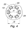
保持面は、オリフィス12に対して垂直に位置する開口部20(図4)を形成し、図5に示すように、上部フランジ8の通過中に変形し、オリフィス12を通って挿入されるときに、その上部フランジ8によって管2を支持するように構成されている。
The retaining surface defines an opening 20 (FIG. 4) that is positioned perpendicular to the
さらに、各脚22は、近位端16からオリフィス12の内側に向かう、斜め上向きの近位部26と、近位部26から保持端18に向かう、垂直上向きの遠位部28とを有している。
Furthermore, each
さらに、各脚22の高さは、オリフィス12に挿入された管2を確実に垂直に保持するために、10~25mm、好ましくは18.5mmで構成されている。
Furthermore, the height of each
近位部26の高さは10~15mmの間、好ましくは13mmで構成され、遠位部28の高さは3~5mmの間、好ましくは4mmで構成される。
The height of the
図4に示すように、開口部20の直径「d」は12.2mmであり、オリフィス12の直径「D」は16mmである。
As shown in FIG. 4, the diameter "d" of the
そのため、開口部20はオリフィス12よりも小さい寸法となっている。
Therefore, the
さらに、上部フランジ8は、14mmの範囲の直径を有している。そのため、オリフィス12と相補的な寸法でありながら、開口部20よりも大きな寸法となっている。
In addition, the
図5は、前述のようにオリフィス12に挿入された管2を含むトレイ10の一部を示している。トレイ10は、ガラス管2を処理するための異なる装置に配置できる、「タブ(Tub)」とも呼ばれる輪郭を形成する標準化された支持体30に調整されている。
Figure 5 shows a portion of a
トレイ10は、支持体30から取り出す際にトレイを把持するために用いられる「鍵穴」の形をしたルーメン17を含んでいる。
The
各オリフィス12は、管2およびそのフランジ6,8の各々を通過するように構成されている。
Each
脚部22によって形成されたオリフィス12の壁Pは、オリフィス12を通る支持位置の管2を保持するように構成されている。
The wall P of the
したがって、各管2は垂直に保持され、上部フランジ8は脚22の保持端18に載る。
Thus, each
脚22は、オリフィス12に挿入された管2の本体4と少なくとも部分的に接触するように構成され、管の追加的な保持を可能にする。
The
脚22の遠位部28が、オリフィス12に挿入されたときに、管2の本体4と接触する。
The
遠位部28は、ガラス管2の本体4の周りで実質的に調整される。
The
オリフィス12内への管2の挿入ため、管2は、トレイ10の底面から、オリフィス12内に垂直に挿入される。
To insert the
管2がトレイ10のオリフィス12に挿入されると、完全なトレイ10は、その支持体30と共に袋に入れられる。この袋は、管の滅菌を行うため密封される。
Once the
プラスチック材料で作製されたバッグは、高密度ポリエチレンを使用して使用され、湿気の通過を減らし、熱伝導がよく、微生物バリアが強く、機械的強度、特に穿孔に対する耐性が高くなる。高密度ポリエチレンは、特に、登録商標「Tyvek」として販売されている素材を使用できる。 Bags made from plastic materials are used using high density polyethylene, which reduces the passage of moisture, has good thermal conductivity, a strong microbial barrier and high mechanical strength, especially resistance to puncture. High density polyethylene can be used in particular the material sold under the registered trademark "Tyvek".
最終包装は、充填準備が整った滅菌済み管を配送するためのシステムのパッケージを指定する、フランス規格「NF ISO 11040-7」に従って行われる。 Final packaging is carried out in accordance with the French standard "NF ISO 11040-7", which specifies the packaging of systems for the delivery of sterile tubes ready for filling.
管2を洗浄した後、シリコーンコーティングが施され、乾熱加熱工程を有するパイロジェン低減法により殺菌されて、発熱物質であるエンドトキシンを強力に低減させる。
After the
特に、240℃での乾熱加熱サイクルは、シリコーンの架橋が同時に行われ、ガラス管 2に充填した後、および、患者への注入装置の最終使用中における、薬剤へのこのシリコーンの放出を実質的に防ぐという利点がある。さらに、この方法は、有毒な物質を導入するエチレンオキシドによる滅菌を回避する。
In particular, the dry heat cycle at 240°C has the advantage that the cross-linking of the silicone is simultaneously performed, substantially preventing its release into the drug after filling into the
Claims (12)
前記保持装置(10)は、複数のオリフィス(12)を備え、前記オリフィス(12)の各々は、管(2)を支持するように設けられていると共に、前記管(2)と前記上部フランジ(8)および前記下部フランジ(6)との各々を通過可能に構成され、
前記保持装置(10)は、複数の保持手段(P)を含み、前記保持手段の各々は、前記上部フランジ(8)により前記オリフィス(12)の1つを通る前記管(2)の1つを保持可能に構成され、
前記保持手段(P)の各々は、弾性的に変形可能な要素(22)を有し、前記弾性的に変形可能な要素(22)は、前記オリフィス(12)に合わせて配置された保持端(18)を含み、
前記保持端(18)は、前記オリフィス(12)を前記上部フランジ(8)が通過しているときに変形可能に構成され、前記管が前記オリフィス(12)に挿入される場合に前記上部フランジ(8)によって前記管(2)を支持し、
前記保持手段(P)が、前記管(2)が前記オリフィス(12)に挿入される場合に、少なくとも部分的に前記管(2)の前記本体(4)と接触するように構成されている、保持装置。 A holding device (10) for holding an injection device tube (2) having an upper flange (8) at one end of a body (4) and a lower flange (6) at the other end of said body (4), comprising:
The holding device (10) includes a plurality of orifices (12), each of which is configured to support a pipe (2) and to allow the pipe (2) and each of the upper flange (8) and the lower flange ( 6) to pass through the orifice (12);
The holding device (10) comprises a plurality of holding means (P), each of which is adapted to hold one of the pipes (2) passing through one of the orifices (12) by means of the upper flange (8);
Each of said retaining means (P) has an elastically deformable element (22) including a retaining end (18) aligned with said orifice (12);
the retaining end (18) is configured to be deformable when the upper flange (8) passes through the orifice (12) and supports the tube (2) by the upper flange (8) when the tube is inserted into the orifice (12) ;
A holding device, wherein said holding means (P) is configured to at least partially contact said body (4) of said tube (2) when said tube (2) is inserted into said orifice (12) .
前記保持端(18)が、前記オリフィス(12)を前記管(2)の前記上部フランジ(8)が通過しているときに変形するように構成され、前記オリフィス(12)に挿入されるときに前記上部フランジ(8)によって前記管(2)を支持するように構成された開口部(20)を構成する、請求項3の保持装置。 said wall (P) having a proximal end (16) in contact with said retention device (10) and a distal end constituting said retention end (18) aligned with said orifice (12);
4. The retaining device of claim 3, wherein the retaining end (18) is configured to deform when the upper flange (8) of the tube (2) passes through the orifice (12) and defines an opening (20) configured to support the tube (2) by the upper flange (8) when inserted into the orifice (12 ) .
本体(4)の一端の上部フランジ(8)および前記本体(4)の他端の下部フランジ(6)をそれぞれ有する複数の注入装置の管(2)であって、前記保持装置(10)のオリフィス(12)に挿入されるようにそれぞれ構成された複数の管(2)と
を備える、アセンブリ。 A holding device (10) according to any one of claims 1 to 9 ,
and a plurality of injection device tubes (2), each having an upper flange (8) at one end of a body (4) and a lower flange (6) at the other end of the body (4), each tube (2) configured to be inserted into an orifice (12) of the retention device (10).
Applications Claiming Priority (3)
| Application Number | Priority Date | Filing Date | Title |
|---|---|---|---|
| FR1859371A FR3087116B1 (en) | 2018-10-10 | 2018-10-10 | DEVICE FOR HOLDING INJECTION DEVICE TUBES |
| FR18/59371 | 2018-10-10 | ||
| PCT/FR2019/052396 WO2020074829A1 (en) | 2018-10-10 | 2019-10-09 | Device for holding injection-device tubes |
Publications (2)
| Publication Number | Publication Date |
|---|---|
| JP2022504649A JP2022504649A (en) | 2022-01-13 |
| JP7462970B2 true JP7462970B2 (en) | 2024-04-08 |
Family
ID=65443983
Family Applications (1)
| Application Number | Title | Priority Date | Filing Date |
|---|---|---|---|
| JP2021519762A Active JP7462970B2 (en) | 2018-10-10 | 2019-10-09 | Holding device for an injection device |
Country Status (11)
| Country | Link |
|---|---|
| US (1) | US11911589B2 (en) |
| EP (1) | EP3863696A1 (en) |
| JP (1) | JP7462970B2 (en) |
| CN (1) | CN112888467B (en) |
| AU (1) | AU2019358536B2 (en) |
| BR (1) | BR112021006137A2 (en) |
| CA (1) | CA3114675A1 (en) |
| FR (1) | FR3087116B1 (en) |
| IL (1) | IL282143B1 (en) |
| MX (1) | MX2021004076A (en) |
| WO (1) | WO2020074829A1 (en) |
Families Citing this family (1)
| Publication number | Priority date | Publication date | Assignee | Title |
|---|---|---|---|---|
| EP4717286A1 (en) * | 2024-09-25 | 2026-04-01 | SCHOTT Pharma Schweiz AG | Nest with bounded openings for lifting and centring of said nest |
Citations (6)
| Publication number | Priority date | Publication date | Assignee | Title |
|---|---|---|---|---|
| JP2001327577A (en) | 2000-03-15 | 2001-11-27 | Carl Zeiss:Fa | Transporting device for medical container |
| DE102012108215A1 (en) | 2012-07-13 | 2014-01-16 | Schott Ag | Method for treating or processing containers used for storing e.g. medical substances, involves automatically passing containers opened at one end, through processing stations for treatment or processing, with conveying device |
| US20140027332A1 (en) | 2012-05-03 | 2014-01-30 | Schott Ag | Holding structure for simultaneously holding a plurality of containers for medical, pharmaceutical or cosmetic applications and transport or packaging container with holding structure |
| US20140034545A1 (en) | 2012-05-03 | 2014-02-06 | Schott Ag | Holding structure for simultaneously holding a plurality of containers for medical, pharmaceutical or cosmetic applications and transport or packaging container with holding structure |
| WO2014112113A1 (en) | 2013-01-21 | 2014-07-24 | テルモ株式会社 | Container for housing syringe barrels |
| US20180110929A1 (en) | 2015-06-30 | 2018-04-26 | Crossject | Needleless injection device equipped with a compression spring |
Family Cites Families (7)
| Publication number | Priority date | Publication date | Assignee | Title |
|---|---|---|---|---|
| CN101652152B (en) * | 2007-03-05 | 2013-03-20 | 株式会社大协精工 | Medical container |
| KR101976097B1 (en) * | 2012-11-12 | 2019-05-09 | 쇼오트 아게 | Method and device for treating or processing containers for substances for medical, pharmaceutical or cosmetic applications |
| US20160097576A1 (en) * | 2014-10-07 | 2016-04-07 | Wojciech Bartkowski | Mold for making tool out of ice |
| IL239366B (en) * | 2015-06-11 | 2018-07-31 | Kriheli Marino | Components of a fluid transfer device |
| KR101589006B1 (en) * | 2015-10-17 | 2016-02-12 | 주식회사 메덱셀 | Safety protection system for pen needles |
| BE1023556B1 (en) * | 2016-07-11 | 2017-05-03 | Nougimmo Sprl | NEST WITH SYRINGES |
| FR3067246B1 (en) * | 2017-06-09 | 2019-08-09 | Crossject | PLATE FOR MAINTAINING DRUG INJECTION DEVICE TUBES |
-
2018
- 2018-10-10 FR FR1859371A patent/FR3087116B1/en active Active
-
2019
- 2019-10-09 EP EP19823798.4A patent/EP3863696A1/en active Pending
- 2019-10-09 WO PCT/FR2019/052396 patent/WO2020074829A1/en not_active Ceased
- 2019-10-09 JP JP2021519762A patent/JP7462970B2/en active Active
- 2019-10-09 BR BR112021006137-1A patent/BR112021006137A2/en active Search and Examination
- 2019-10-09 AU AU2019358536A patent/AU2019358536B2/en active Active
- 2019-10-09 IL IL282143A patent/IL282143B1/en unknown
- 2019-10-09 CA CA3114675A patent/CA3114675A1/en active Pending
- 2019-10-09 MX MX2021004076A patent/MX2021004076A/en unknown
- 2019-10-09 CN CN201980067175.5A patent/CN112888467B/en active Active
-
2021
- 2021-04-12 US US17/227,550 patent/US11911589B2/en active Active
Patent Citations (6)
| Publication number | Priority date | Publication date | Assignee | Title |
|---|---|---|---|---|
| JP2001327577A (en) | 2000-03-15 | 2001-11-27 | Carl Zeiss:Fa | Transporting device for medical container |
| US20140027332A1 (en) | 2012-05-03 | 2014-01-30 | Schott Ag | Holding structure for simultaneously holding a plurality of containers for medical, pharmaceutical or cosmetic applications and transport or packaging container with holding structure |
| US20140034545A1 (en) | 2012-05-03 | 2014-02-06 | Schott Ag | Holding structure for simultaneously holding a plurality of containers for medical, pharmaceutical or cosmetic applications and transport or packaging container with holding structure |
| DE102012108215A1 (en) | 2012-07-13 | 2014-01-16 | Schott Ag | Method for treating or processing containers used for storing e.g. medical substances, involves automatically passing containers opened at one end, through processing stations for treatment or processing, with conveying device |
| WO2014112113A1 (en) | 2013-01-21 | 2014-07-24 | テルモ株式会社 | Container for housing syringe barrels |
| US20180110929A1 (en) | 2015-06-30 | 2018-04-26 | Crossject | Needleless injection device equipped with a compression spring |
Also Published As
| Publication number | Publication date |
|---|---|
| AU2019358536A1 (en) | 2021-06-03 |
| CN112888467A (en) | 2021-06-01 |
| MX2021004076A (en) | 2021-06-04 |
| IL282143B1 (en) | 2026-04-01 |
| FR3087116B1 (en) | 2024-06-21 |
| BR112021006137A2 (en) | 2021-06-29 |
| EP3863696A1 (en) | 2021-08-18 |
| CN112888467B (en) | 2023-04-28 |
| CA3114675A1 (en) | 2020-04-16 |
| AU2019358536B2 (en) | 2025-01-02 |
| US11911589B2 (en) | 2024-02-27 |
| FR3087116A1 (en) | 2020-04-17 |
| WO2020074829A1 (en) | 2020-04-16 |
| IL282143A (en) | 2021-05-31 |
| US20210236716A1 (en) | 2021-08-05 |
| JP2022504649A (en) | 2022-01-13 |
Similar Documents
| Publication | Publication Date | Title |
|---|---|---|
| CN110461371B (en) | Sterilization method | |
| JP4638553B1 (en) | Manufacturing method and front stopper of two-chamber syringe | |
| CN100512881C (en) | Vacuum sterilization process and devices | |
| JP7286555B2 (en) | Retaining tray for tube for drug injection device | |
| US3596660A (en) | Injection device | |
| EP2020245B1 (en) | Method for making a device for ophthalmic treatments | |
| EP2626097A1 (en) | Device for accomodating a freeze-dried pharmaceutical product and method of manufacturing a sealed vessel accomodating a freeze-dried pharmaceutical product | |
| US2634856A (en) | Sterile pack for individual disassembled syringes | |
| EP2809290A1 (en) | Adaptor for coupling to a medical container | |
| KR20230167403A (en) | Sterilization methods and systems | |
| EA037154B1 (en) | Vented cover plate for an array of syringes | |
| CN104363889B (en) | Improvement injection | |
| WO2013115731A1 (en) | Adaptor for coupling to a medical container | |
| JP7462970B2 (en) | Holding device for an injection device | |
| JP2007209675A (en) | Manufacturing method of prefilled syringe | |
| CN106742610B (en) | Double-deck aseptic packaging structure of plastics ampoule injection | |
| JPS63286156A (en) | Folded container and method for folding the same | |
| WO2026019886A1 (en) | Methods for enhanced sterilization of packaged, pre-filled syringes and contents of the pre-filled syringe | |
| JP2698524C (en) | ||
| Mantsch et al. | Fluidose II a Semi-automatic Method Used in Filling Unit-of-use Syringes |
Legal Events
| Date | Code | Title | Description |
|---|---|---|---|
| A521 | Request for written amendment filed |
Free format text: JAPANESE INTERMEDIATE CODE: A523 Effective date: 20210610 |
|
| A621 | Written request for application examination |
Free format text: JAPANESE INTERMEDIATE CODE: A621 Effective date: 20220810 |
|
| A977 | Report on retrieval |
Free format text: JAPANESE INTERMEDIATE CODE: A971007 Effective date: 20230630 |
|
| A131 | Notification of reasons for refusal |
Free format text: JAPANESE INTERMEDIATE CODE: A131 Effective date: 20230704 |
|
| A601 | Written request for extension of time |
Free format text: JAPANESE INTERMEDIATE CODE: A601 Effective date: 20230929 |
|
| A521 | Request for written amendment filed |
Free format text: JAPANESE INTERMEDIATE CODE: A523 Effective date: 20231225 |
|
| TRDD | Decision of grant or rejection written | ||
| A01 | Written decision to grant a patent or to grant a registration (utility model) |
Free format text: JAPANESE INTERMEDIATE CODE: A01 Effective date: 20240312 |
|
| A61 | First payment of annual fees (during grant procedure) |
Free format text: JAPANESE INTERMEDIATE CODE: A61 Effective date: 20240319 |
|
| R150 | Certificate of patent or registration of utility model |
Ref document number: 7462970 Country of ref document: JP Free format text: JAPANESE INTERMEDIATE CODE: R150 |