JP7425516B1 - Concrete retaining wall and concrete retaining wall construction method - Google Patents
Concrete retaining wall and concrete retaining wall construction method Download PDFInfo
- Publication number
- JP7425516B1 JP7425516B1 JP2023069689A JP2023069689A JP7425516B1 JP 7425516 B1 JP7425516 B1 JP 7425516B1 JP 2023069689 A JP2023069689 A JP 2023069689A JP 2023069689 A JP2023069689 A JP 2023069689A JP 7425516 B1 JP7425516 B1 JP 7425516B1
- Authority
- JP
- Japan
- Prior art keywords
- vertical wall
- earth
- concrete
- fence
- hole
- Prior art date
- Legal status (The legal status is an assumption and is not a legal conclusion. Google has not performed a legal analysis and makes no representation as to the accuracy of the status listed.)
- Active
Links
- 238000010276 construction Methods 0.000 title claims abstract description 38
- 230000003014 reinforcing effect Effects 0.000 claims abstract description 74
- 239000004576 sand Substances 0.000 claims abstract description 56
- 230000035515 penetration Effects 0.000 claims abstract description 28
- 239000002689 soil Substances 0.000 claims description 11
- 238000000034 method Methods 0.000 claims description 10
- 238000010586 diagram Methods 0.000 abstract 1
- 239000012779 reinforcing material Substances 0.000 description 5
- 238000009434 installation Methods 0.000 description 4
- 230000000452 restraining effect Effects 0.000 description 4
- 239000013049 sediment Substances 0.000 description 4
- 239000002184 metal Substances 0.000 description 3
- 230000002787 reinforcement Effects 0.000 description 3
- 238000000151 deposition Methods 0.000 description 2
- 230000000694 effects Effects 0.000 description 2
- 239000004570 mortar (masonry) Substances 0.000 description 2
- 238000005452 bending Methods 0.000 description 1
- 230000008014 freezing Effects 0.000 description 1
- 238000007710 freezing Methods 0.000 description 1
- 238000003780 insertion Methods 0.000 description 1
- 230000037431 insertion Effects 0.000 description 1
- 239000000463 material Substances 0.000 description 1
- 238000005507 spraying Methods 0.000 description 1
- XLYOFNOQVPJJNP-UHFFFAOYSA-N water Substances O XLYOFNOQVPJJNP-UHFFFAOYSA-N 0.000 description 1
- 239000002023 wood Substances 0.000 description 1
Images


Landscapes
- Retaining Walls (AREA)
- Fencing (AREA)
Abstract
【課題】 フェンスなどが設置されるコンクリート擁壁であっても、土砂の土圧や強風によって擁壁が滑動しまうことを極力防止することを目的とする。
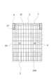
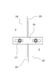
【解決手段】 天面2Cにフェンス4等の支柱8が挿入される支柱用穴9が形成され、鉛直方向に延在するとともに、前面2Aと背面2Bの厚さが一定の矩形状をなすたて壁2と、このたて壁2の背面2Bの下端から水平方向に延在する底版3とを、コンクリートにてL型に一体成形し、たて壁2の背面2Bにて底版3上の土砂の土圧を受ける態様のL型コンクリート擁壁1の施工と、たて壁2の前面2Aにて土砂の土圧を受けると共に、所定の根入れ深さDFを有する態様の逆L型コンクリート擁壁1の施工と、のいずれの態様であっても使用することが可能であって、前記たて壁2の前面2A及び背面2Bの両側のコンクリート内に、正面視で全面に配置された前面側鉄筋10A及び背面側鉄筋10Bを備えている。
【選択図】図1
[Problem] The purpose is to prevent as much as possible the retaining wall from sliding due to the earth pressure of earth and sand or strong winds, even if the retaining wall is a concrete retaining wall on which a fence or the like is installed.
[Solution] A post hole 9 into which a post 8 of a fence 4 or the like is inserted is formed in the top surface 2C, extends in the vertical direction, and has a rectangular shape with a constant thickness on the front surface 2A and the back surface 2B. The vertical wall 2 and the bottom plate 3 extending horizontally from the lower end of the back surface 2B of the vertical wall 2 are integrally molded in an L-shape using concrete. Construction of an L-shaped concrete retaining wall 1 that receives the earth pressure of earth and sand, and inverted L-shaped concrete that receives the earth pressure of earth and sand at the front surface 2A of the vertical wall 2 and has a predetermined penetration depth DF. It can be used in either construction of the retaining wall 1, and is placed entirely in the concrete on both sides of the front 2A and back 2B of the vertical wall 2 when viewed from the front. It includes front side reinforcing bars 10A and back side reinforcing bars 10B.
[Selection diagram] Figure 1
Description
本発明は、水平方向に延在する底版と、この底版から垂直方向に延在するたて壁とで構成するコンクリート擁壁であって、特にこのたて壁にフェンス等を設置することができるコンクリート擁壁に関する。 The present invention is a concrete retaining wall composed of a bottom plate extending in the horizontal direction and a vertical wall extending from the bottom plate in the vertical direction, and in particular, a fence or the like can be installed on the vertical wall. Concerning concrete retaining walls.
従来から自己の所有する敷地と道路との境界や、隣接する他人の土地との境界を区画するためなどに、コンクリートブロックが用いられている。特に、高低差のある土地の場合、側面の土が崩れるのを防ぐために、たて壁と底版によって構成されたコンクリート製のL型擁壁が用いられている。そして、特許文献1にはこのような底版とたて壁に相当する平面部、垂直部を有するコンクリート製のL型擁壁が開示されている。
Concrete blocks have traditionally been used to delineate the boundaries between one's own property and a road, or to delineate the boundaries between adjacent land belonging to other people. Particularly in the case of land with differences in elevation, L-shaped concrete retaining walls made of vertical walls and bottom slabs are used to prevent the soil on the sides from collapsing.
この特許文献1に記載のL型擁壁は、平面部、垂直部に補強材が設けられておらずコンクリートで成型するのみであった。ところで、このようなコンクリート製品については、応力(外力)が加わる面に近い位置に補強材(鉄筋)が埋設されることが一般的である。
The L-shaped retaining wall described in
例えば、L型擁壁の垂直部内側(平面部上側)に土砂を堆積する場合は、その垂直部においては厚さの半分の位置から内側に偏位した位置に格子状鉄筋を埋設してある。一方、L型擁壁の垂直部外側に土砂を堆積する場合は、土砂側に偏位した位置に鉄筋を埋設したそれを使用する。すなわち、住宅建設予定地の地形的な条件などに対応して鉄筋埋設位置が異なる2種類のL型擁壁を準備し、これらを適切に選択配置して宅地などを造成することとしている。 For example, when depositing earth and sand on the inside of the vertical part (above the flat part) of an L-shaped retaining wall, lattice reinforcing bars are buried in the vertical part at a position offset inward from half the thickness. . On the other hand, when depositing earth and sand on the outside of the vertical part of an L-shaped retaining wall, reinforcing bars are buried in positions deviated to the earth and sand side. In other words, two types of L-shaped retaining walls with different reinforcing bars are prepared depending on the topographical conditions of the site where a house is planned to be built, and these are appropriately selected and arranged to create a residential lot.
しかし、垂直部において厚さの半分の位置から内側に偏位した位置に格子状鉄筋を埋設してあるL型擁壁しか準備できなかった場合、垂直部の外面に堆積土砂等が接触する条件で、L型擁壁を施工すると、鉄筋の偏位関係から土圧による曲げ耐力に抵抗できずに、垂直部の下部において堆積土砂等に接触する面から堆積土砂等に接触していない面に向かってひび割れが発生し、時間の経過とともに鉄筋が腐食して垂直部が堆積土砂等によって押し倒されることになり問題となっていた。 However, if only an L-shaped retaining wall with lattice-shaped reinforcing bars buried at a position offset inward from the half-thickness position in the vertical part could be prepared, there would be a condition where accumulated soil, etc. would come into contact with the outer surface of the vertical part. When an L-shaped retaining wall is constructed, it cannot resist the bending strength due to earth pressure due to the deviation of the reinforcing bars, and the lower portion of the vertical section is moved from the surface that contacts the accumulated earth and sand to the surface that does not contact the accumulated earth and sand. Cracks appeared in the direction, and over time the reinforcing bars corroded, causing vertical sections to be pushed down by accumulated earth and sand, which became a problem.
この問題を解決するため、特許文献2では、金属製補強材(鉄筋)の埋設位置および90度で直交する平面部および垂直部の長さに着目し、平面部および垂直部にそれぞれ金属製補強材を埋設し、かつそれぞれの側面視して短辺の中央(厚みの半分の位置)に位置するようこれらの金属製補強材を配置することにより、1種類のL型コンクリート擁壁を2態様(平面部を埋設した態様、埋設しない態様)に設置して使用することができるL型擁壁用コンクリート製品が開示されている。
In order to solve this problem,
しかしながら、この特許文献2では、平面部の上面は所定深さの堆積土砂等で埋もれ、露出面は上記垂直部の堆積土砂等に接触しない面のみとする施工と、平面部の上面に堆積土砂等が接することなく、垂直部の一面のみに堆積土砂等が接する施工と、のいずれの態様であっても使用することが可能であるが、平面部の上面に堆積土砂等が接することなく、垂直部の一面のみに堆積土砂等が接する場合、平面部には何らの押さえもないため、L型擁壁が堆積土砂の土圧に押されて平面部方向に滑動してしまう恐れがある。
However, in this
特に、L型擁壁の垂直部に風の影響を受けやすい目隠しフェンスなどを設置する場合、堆積土砂の土圧に加えて強風の影響も受けるため、L型擁壁が滑動して堆積土砂が崩れてしまうという問題があった。 In particular, when installing a blind fence etc. on the vertical part of an L-shaped retaining wall, which is susceptible to the effects of wind, the L-shaped retaining wall will slide and the accumulated soil will be affected by strong winds in addition to the earth pressure of the accumulated soil. There was a problem with it falling apart.
本発明は、このような問題点に鑑みてなされたもので、フェンスなどが設置されるコンクリート擁壁であっても、土砂の土圧や強風によって擁壁が滑動しまうことを極力防止することを目的とする。 The present invention was made in view of these problems, and aims to prevent as much as possible the retaining wall from sliding due to the earth pressure of earth and sand and strong winds, even if it is a concrete retaining wall on which a fence or the like is installed. purpose.
本発明の請求項1にかかるコンクリート擁壁は、天面にフェンス等の支柱が挿入される支柱用穴が形成され、鉛直方向に延在するとともに、前面と背面の厚さが一定の矩形状をなすたて壁と、該たて壁の背面の下端から水平方向に延在する底版とを、コンクリートにてL型に一体成形し、前記たて壁の前面側表面と前記支柱用穴との間の板厚、及び背面側表面と前記支柱用穴との間の板厚を、たて壁の板厚の1/3~1/10とするとともに、支柱用穴を囲うようにコンクリート内に支柱穴鉄筋を配置し、前記支柱用穴の底部と連通するとともに、たて壁側面に開口する排水孔を形成し、たて壁の背面にて底版上の土砂の土圧を受ける態様の施工と、たて壁の前面にて土砂の土圧を受けると共に、所定の根入れ深さを有する態様の施工と、のいずれの態様であっても使用することが可能であって、前記たて壁の前面及び背面の両側のコンクリート内に正面視で全面に配置され、上下方向に延在する主筋と、この主筋を拘束する帯筋とよりなる鉄筋を備えたことを特徴とする。
The concrete retaining wall according to
本発明の請求項2にかかるコンクリート擁壁は、請求項1において、フェンス等の支柱が横断面角形状または丸形状のいずれの形状であっても挿入可能な角丸長方形状の支柱用穴を備えたことを特徴とする。
In the concrete retaining wall according to
本発明の請求項3にかかるコンクリート擁壁の施工方法は、天面にフェンス等の支柱が挿入される支柱用穴が形成され、鉛直方向に延在するとともに、前面と背面の厚さが一定の矩形状をなすたて壁と、該たて壁の背面の下端から水平方向に延在する底版とを、コンクリートにてL型に一体成形し、前記たて壁の前面側表面と前記支柱用穴との間の板厚、及び背面側表面と前記支柱用穴との間の板厚を、たて壁の板厚の1/3~1/10とするとともに、支柱用穴を囲うようにコンクリート内に支柱穴鉄筋を配置し、前記支柱用穴の底部と連通するとともに、たて壁側面に開口する排水孔を形成し、たて壁の背面にて底版上の土砂の土圧を受ける態様の施工と、たて壁の前面にて土砂の土圧を受けると共に、所定の根入れ深さを有する態様の施工と、のいずれの態様であっても使用することが可能であって、前記たて壁の前面及び背面の両側のコンクリート内に、正面視で全面に配置され、上下方向に延在する主筋と、この主筋を拘束する帯筋とよりなる鉄筋を備え、前記たて壁の前面にて土砂の土圧を受ける態様の施工の場合、前記底版の延在方向の長さBに対する根入れ深さDFの比率DF/Bを0.43以上としたことを特徴とする。
In the method for constructing a concrete retaining wall according to
本発明の請求項4にかかるコンクリート擁壁の施工方法は、天面にフェンスの支柱が挿入される支柱用穴が形成され、鉛直方向に延在するとともに、前面と背面の厚さが一定の矩形状をなすたて壁と、該たて壁の背面の下端から水平方向に延在する底版とを、コンクリートにてL型に一体成形し、前記たて壁上に、たて壁とほぼ同じ幅であって、且つ所定高さFHの目隠しフェンスを設置し、前記たて壁の前面側表面と前記支柱用穴との間の板厚、及び背面側表面と前記支柱用穴との間の板厚を、たて壁の板厚の1/3~1/10とするとともに、支柱用穴を囲うようにコンクリート内に支柱穴鉄筋を配置し、前記支柱用穴の底部と連通するとともに、たて壁側面に開口する排水孔を形成し、たて壁の背面にて底版上の土砂の土圧を受ける態様の施工と、たて壁の前面にて土砂の土圧を受けると共に、所定の根入れ深さを有する態様の施工と、のいずれの態様であっても使用することが可能であって、前記たて壁の前面及び背面の両側のコンクリート内に正面視で全面に配置され、上下方向に延在する主筋と、この主筋を拘束する帯筋とよりなる鉄筋を備え、前記たて壁の前面にて土砂の土圧を受ける態様の施工の場合、たて壁の高さHとフェンス高さFHとを加算した寸法に対する根入れ深さDFの比率DF/(FH+H)を0.13以上としたことを特徴とする。
In the method for constructing a concrete retaining wall according to
本発明の請求項5にかかるコンクリート擁壁の施工方法は、天面にフェンスの支柱が挿入される支柱用穴が形成され、鉛直方向に延在するとともに、前面と背面の厚さが一定の矩形状をなすたて壁と、該たて壁の背面の下端から水平方向に延在する底版とを、コンクリートにてL型に一体成形し、前記たて壁上に、たて壁とほぼ同じ幅であって、且つ所定高さFHの目隠しフェンスを設置し、前記たて壁の前面側表面と前記支柱用穴との間の板厚、及び背面側表面と前記支柱用穴との間の板厚を、たて壁の板厚の1/3~1/10とするとともに、支柱用穴を囲うようにコンクリート内に支柱穴鉄筋を配置し、前記支柱用穴の底部と連通するとともに、たて壁側面に開口する排水孔を形成し、たて壁の背面にて底版上の土砂の土圧を受ける態様の施工と、たて壁の前面にて土砂の土圧を受けると共に、所定の根入れ深さを有する態様の施工と、のいずれの態様であっても使用することが可能であって、前記たて壁の前面及び背面の両側のコンクリート内に、正面視で全面に配置され、上下方向に延在する主筋と、この主筋を拘束する帯筋とよりなる鉄筋を備え、前記フェンスの高さFHに対する支柱の埋め込み深さDの比率D/FHを0.17以上としたことを特徴とする。
In the method for constructing a concrete retaining wall according to
本発明にかかるコンクリート擁壁は、天面にフェンス等の支柱が挿入される支柱用穴が形成され、鉛直方向に延在するとともに、前面と背面の厚さが一定の矩形状をなすたて壁と、このたて壁の背面の下端から水平方向に延在する底版とを、コンクリートにてL型に一体成形し、 The concrete retaining wall according to the present invention has a post hole formed in the top surface into which a post such as a fence is inserted, extends vertically, and has a rectangular shape with constant thickness on the front and back sides. The wall and the bottom plate extending horizontally from the lower end of the back of this vertical wall are integrally formed into an L-shape using concrete.
前記たて壁の前面側表面と前記支柱用穴との間の板厚、及び背面側表面と前記支柱用穴との間の板厚を、たて壁の板厚の1/3~1/10とするとともに、支柱用穴を囲うようにコンクリート内に支柱穴鉄筋を配置し、前記支柱用穴の底部と連通するとともに、たて壁側面に開口する排水孔を形成し、The thickness between the front surface of the vertical wall and the support hole, and the thickness between the back surface and the support hole, are set to 1/3 to 1/3 of the thickness of the vertical wall. 10, a post hole reinforcing bar is placed in the concrete to surround the post hole, and a drainage hole is formed that communicates with the bottom of the post hole and opens on the side surface of the vertical wall,
たて壁の背面にて底版上の土砂の土圧を受ける態様の施工と、たて壁の前面にて土砂の土圧を受けると共に、所定の根入れ深さを有する態様の施工と、のいずれの態様であっても使用することが可能であって、前記たて壁の前面及び背面の両側のコンクリート内に正面視で全面に配置され、上下方向に延在する主筋と、この主筋を拘束する帯筋とよりなる鉄筋を備えているため、 There are two types of construction: one in which the back of the vertical wall receives the earth pressure of the earth and sand on the bottom slab, and the other in which the front of the vertical wall receives the earth pressure of the earth and sand and has a predetermined penetration depth. It is possible to use either mode, and the main reinforcement is placed in the concrete on both sides of the front and back of the vertical wall and extends in the vertical direction. Because it is equipped with restraining ties and reinforcing bars ,
たて壁の背面側であって底版上の土砂は、たて壁背面側の鉄筋にて土圧を受け、たて壁の前面側の土砂は、たて壁正面側の鉄筋にて土圧を受けるものである。即ち、L型コンクリート擁壁、逆L型コンクリート擁壁いずれの態様の施工であっても、土砂の土圧によるたて壁の損傷を極力防止できる。 The earth and sand on the bottom slab on the back side of the vertical wall is subjected to earth pressure by the reinforcing bars on the back side of the vertical wall, and the earth and sand on the front side of the vertical wall is subjected to earth pressure by the reinforcing bars on the front side of the vertical wall. It is something that receives. That is, regardless of whether an L-shaped concrete retaining wall or an inverted L-shaped concrete retaining wall is constructed, damage to the vertical wall due to the earth pressure of earth and sand can be prevented as much as possible.
また、たて壁の前面にて土砂の土圧を受ける態様の施工の場合、所定深さの根入れを行うことにより、風の影響を受けやすいフェンス等を設置したコンクリート擁壁であっても、土砂の土圧や強風によってコンクリート擁壁が滑動しまうことを極力防止することができる。 In addition, in the case of construction in which the front of the vertical wall is subject to earth pressure from earth and sand, it is possible to install concrete retaining walls with fences etc. that are easily affected by wind by planting the roots to a specified depth. , it is possible to prevent the concrete retaining wall from sliding due to the earth pressure of earth and sand and strong winds as much as possible.
また、本発明のコンクリート擁壁では、前記支柱用穴の底部と連通するとともに、たて壁側面に開口する排水孔を形成している。このため、コンクリート擁壁を屋外で保管する場合でも、支柱用穴に流れ込んだ雨水を排水孔で排水することができ、冬場などに溜まった雨水が氷結して支柱用穴を破損してしまうことを防止できる。 Moreover, in the concrete retaining wall of the present invention , a drainage hole is formed that communicates with the bottom of the support hole and opens on the side surface of the vertical wall. Therefore, even if the concrete retaining wall is stored outdoors, rainwater that has flowed into the support holes can be drained through the drainage holes, preventing accumulated rainwater from freezing and damaging the support holes in winter. can be prevented.
更に、本発明のコンクリート擁壁では、前記たて壁の前面側表面と前記支柱用穴との間の板厚、及び背面側表面と前記支柱用穴との間の板厚を、たて壁の板厚の1/3~1/10としている。このため、フェンスが強風を受けて支柱に負荷がかかっても支柱用穴周辺にひび割れ、欠け等の破損が発生してしまうことを極力防止できる。 Furthermore, in the concrete retaining wall of the present invention , the plate thickness between the front surface of the vertical wall and the support hole, and the plate thickness between the back surface and the support hole, The thickness is 1/3 to 1/10 of the plate thickness. Therefore, even if the fence is exposed to strong winds and a load is applied to the pillars, damage such as cracks and chips around the pillar holes can be prevented as much as possible.
本発明の請求項2にかかるコンクリート擁壁では、フェンス等の支柱が横断面角形状または丸形状のいずれの形状であっても挿入可能な角丸長方形状の支柱用穴を備えたているため、支柱用穴の開け直しなどを不要とし、フェンス設置作業の作業性向上を図ることができる。
The concrete retaining wall according to
本発明の請求項3にかかるコンクリート擁壁の施工方法は、前記たて壁の前面にて土砂の土圧を受ける態様の施工の場合、前記底版の延在方向の長さBに対する根入れ深さDFの比率DF/Bを0.43以上とすることで、土砂の土圧や強風によるコンクリート擁壁の滑動を極力防止できる。
In the method for constructing a concrete retaining wall according to
本発明の請求項4にかかるコンクリート擁壁の施工方法は、たて壁上に、たて壁とほぼ同じ幅であって、且つ所定高さFHの目隠しフェンスを設置し、前記たて壁の前面にて土砂の土圧を受ける態様の施工の場合であっても、たて壁の高さHとフェンス高さFHとを加算した寸法に対する根入れ深さDFの比率DF/(FH+H)を0.13以上とすることで、土砂の土圧や強風によるコンクリート擁壁の滑動を極力防止できる。
The method for constructing a concrete retaining wall according to
本発明の請求項5にかかるコンクリート擁壁の施工方法は、たて壁上に、たて壁とほぼ同じ幅であって、且つ所定高さFHの目隠しフェンスを設置しても、前記たて壁の支柱用穴を囲うようにコンクリート内に鉄筋を備えているため、フェンスが強風を受けても支柱用穴周辺にひび割れ、欠け等の破損が発生してしまうことを極力防止できる。
The method for constructing a concrete retaining wall according to
また、前記フェンスの高さFHに対する支柱の埋め込み深さDの比率D/FHを0.17以上とすることで、強風により支柱が抜けてフェンスが脱落してしまうことを極力防止できる。 Further, by setting the ratio D/FH of the embedded depth D of the pillars to the height FH of the fence to be 0.17 or more, it is possible to prevent the pillars from coming off due to strong winds and the fence from falling off as much as possible.
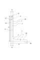
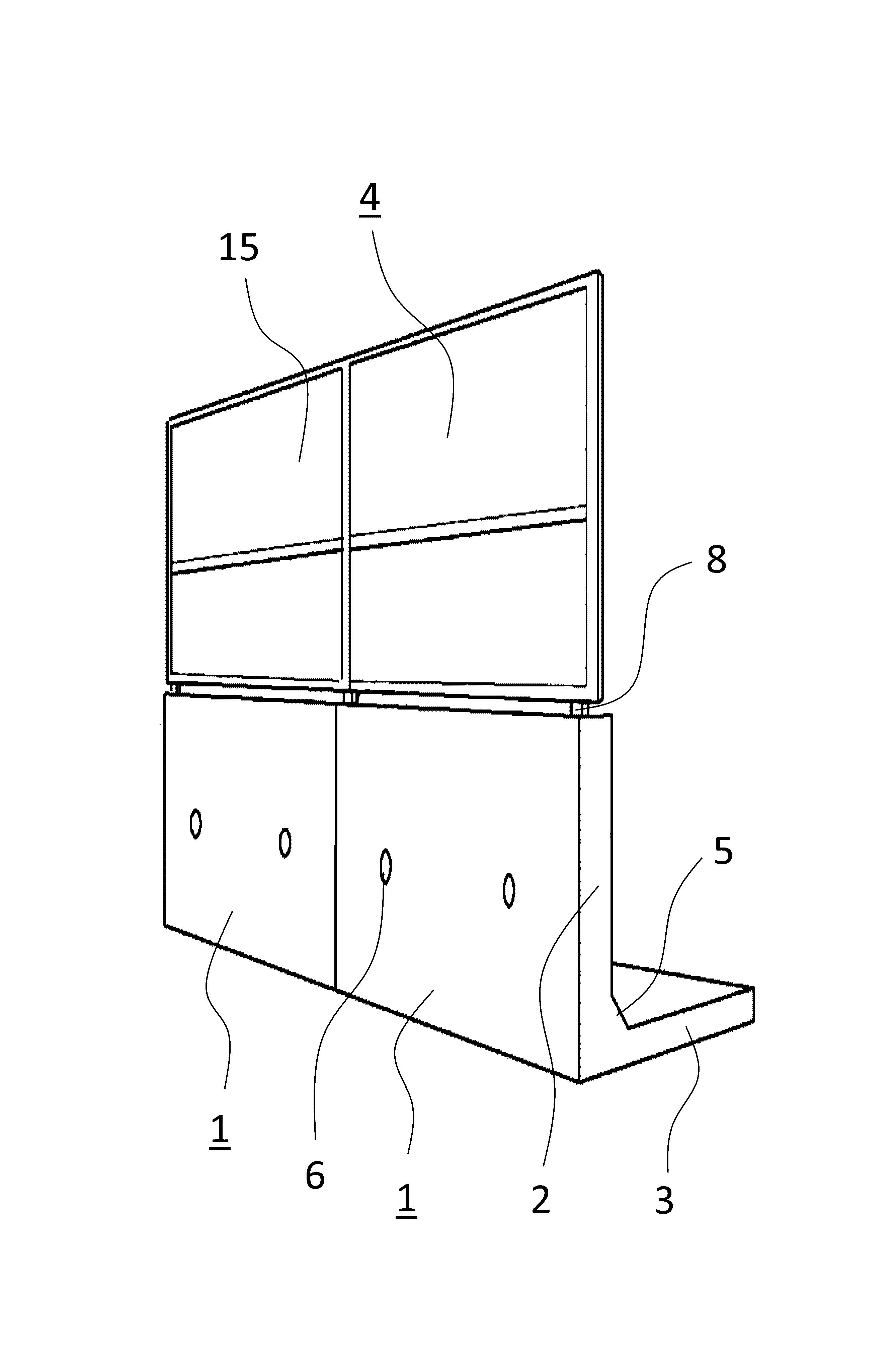
図1に示す1は本発明のL型コンクリート擁壁であり、高低差のある土地で、側面の土が崩れるのを防ぐために設置される壁状の構造物のうち、特に側面視でL型をなすものである。即ち、鉛直方向に延在するたて壁2と、このたて壁2の下端から水平方向に延在する底版3とを、プレキャスト工法によりコンクリートにてL字状に一体成形したものである。
1 shown in Fig. 1 is an L-shaped concrete retaining wall of the present invention, which is especially L-shaped when viewed from the side among wall-like structures installed to prevent soil from collapsing on the sides on land with height differences. It is something that does. That is, a
また、道路に沿って設置されるL型コンクリート擁壁1には、自動車、自転車、あるいは歩行者用のガードフェンス等を、戸建て住宅やマンション等の隣地との境界に設置されるL型コンクリート擁壁1には、図2に示すような目隠しフェンス4が設置されるものである。
以下、図面を参照して本発明の実施例1を詳述する。
In addition, the L-shaped
図1、図3乃至図5に示す如く、本発明のL型コンクリート擁壁1はたて壁2及び底版3とよりなり、たて壁2は矩形の平板状をなしており、上下にわたってほぼ均一な板厚、即ち上側板厚T1と下側板厚T2とがほぼ同じ厚みとなっている。また、底版3はたて壁2に接続している部分から先端に向けて下方傾斜状に形成されており、底版3とたて壁2の接続部分にはたて壁2の補強としてのハンチ5が形成されている。
As shown in FIGS. 1, 3 to 5, the L-shaped
たて壁2は底版3が延在しない側が前面2A、延在する側が背面2Bであって、左右2箇所に前面2Aと背面2Bとを貫通する水抜孔6が穿設されている。この水抜孔6は円錐台状をなしており、前面側2Aの直径の方が背面2B側の直径より大きく形成されている。尚、7はL型コンクリート擁壁1をクレーン等で施工する際に用いる吊り金具を取り付けるための施工用アンカーである。
The
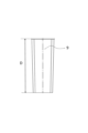
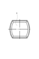
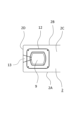
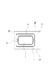
また、たて壁2の天面2Cにはフェンス4等の支柱8が挿入される支柱用穴9が形成されており、この支柱用孔9は図6に示す如く、上面開口から穴底面に向けて徐々に小さいくなるよう下方傾斜状に形成され、図7に示す如く、平面視で角丸長方形状、即ち、二本の平行な直線と、相対向する2本の凹状曲線とよりなる形状に形成されている。これにより、支柱8の横断面形状が丸形状であっても角形状であっても挿入できるものである。
In addition, a
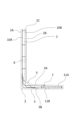
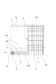
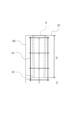
更に、図8乃至図11に示す如く、L型コンクリート擁壁1のたて壁2には、たて壁2の前面2A側及び背面2B側のコンクリート内に、正面視でほぼ全面にわたって前面側鉄筋10A、背面側鉄筋10Bが配置されている。この各鉄筋10A、10Bは上下方向に延在する主筋と、この主筋を拘束する帯筋とによりなるもので、前面2A、背面2B表面から所定間隔離して配置されている。尚、本実施例1のL型コンクリート擁壁1は、直接土に接する壁であるため最低40mm以上離されている。
Furthermore, as shown in FIGS. 8 to 11, in the
前述したたて壁2の下端から延在する底版3もたて壁2同様、上面3A側及び下面3B側のコンクリート内に、平面視でほぼ全面にわたって上面側鉄筋11A、下面側鉄筋11Bが配置されている。この鉄筋11A、11Bも主筋と帯筋とよりなるもので、上面3A、下面3B表面から所定間隔離して配置されている。ここで、底版3の上面3Aは先端に向けて下降傾斜状になっているため、この上面側鉄筋11Aも上面3Aの傾斜に合わせて配置されているものである。
As with the
前記たて壁2の天面2Cの支柱用穴9の周囲のコンクリート内にも、穴9を囲うように支柱穴鉄筋12が設けられており、この支柱穴鉄筋12により、フェンス4に強風が吹き付けて支柱8に大きな力が加わっても支柱用穴9が破損してしまうことを極力防止できるものである。
Post
また、この支柱用穴9の底部には、徐々に拡大する円錐台状の排水孔13が接続されており、前記たて壁2の側面2Dに開口している。ここで、工場でプレキャスト工法により製造されたL型コンクリート擁壁1はその大きさのため屋外で保管するものである。このため、支柱用穴9に雨水が流れ込んでしまい、特に冬場など支柱用穴9に雨水がたまると水が氷結して支柱用穴9を破損してしまう恐れがある。これを防止するため、L型コンクリート擁壁1保管時に支柱用穴9に流れ込んだ雨水を排水孔13にて排水するものである。
Further, a truncated
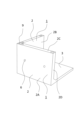
一方、図2に示す如く、本実施例1で用いられるフェンス4は、目隠しフェンスと呼ばれ、幅広の板状のものを重ねて隙間が小さくなるようにしたパネル15と支柱8とよりなるもので、外からの視線をさえぎることを目的としたフェンスである。また、フェンス幅FWは2000mmで、フェンス高さFHは1800mmであるが、これに限定されることなく、フェンス高さFHが600mm~2000mm程度のものであっても良い。
On the other hand, as shown in FIG. 2, the
このように、目隠しフェンスは、フェンス高さFHが高く、更にパネル15の板間の隙間が小さいため風の影響を受けやすいものであるが、前述した如く、支柱用穴9を囲うように支柱穴鉄筋12が設けられているため、フェンス4に強風、例えば風速∨30~38m/sのような風が吹き付け、支柱8に大きな力が加わっても支柱用穴9が破損してしまうことを極力防止できるものである。
In this way, the blind fence is easily affected by the wind because the fence height FH is high and the gap between the
尚、設置されるフェンス4は目隠しフェンスのほか、高さ600mm~1500mm程度で網目状のメッシュフェンスや木目調、縦格子、横格子等の他のフェンスを用いても良いし、道路沿いであれば自動車用のガードレール、自転車、あるいは歩行者用のガードフェンス等であっても良い。
In addition to the blind fence, the
以上のようなL型コンクリート擁壁1を施工する場合、クレーン等で設置場所にL型コンクリート擁壁1を設置する。そして、複数台並設する場合には、L型コンクリート擁壁1同士の側面2D同士を対向させ、図14に示す板状接続金具16を両L型コンクリート擁壁1間に配置し、ボルト等の固定具17で固定する。
When constructing the L-shaped
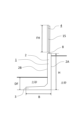
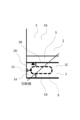
自宅側の土地が高く、周辺の土地が低い場合の例にあげると、通常のL型コンクリート擁壁1は図15に示す如く底版3が位置する側の土地が自宅側であって、自宅側の土地が高い場所などに採用されるものである。しかし本発明の本発明のL型コンクリート擁壁1では、図16に示すような自宅側の土地が低い場合でも逆L型コンクリート擁壁1として用いることができるものである。
To take an example where the land on the home side is high and the surrounding land is low, in a normal L-shaped
即ち、L型コンクリート擁壁1はたて壁2に前面側鉄筋10Aと 背面側鉄筋10Bを備えているため、前面2A側、背面2B側いずれの土圧も受けることができるため、L型コンクリート擁壁としても、逆L型コンクリート擁壁としても用いることができるものである。
In other words, since the L-shaped
但し、この逆L型コンクリート擁壁1として使用する場合には、必要に応じて底版3上に土を盛って根入れを行うものである。以下、この根入れ深さDFと、フェンス4、L型コンクリート擁壁1の寸法との関係を説明する。
However, when used as this inverted L-shaped
尚、図中HはL型コンクリート擁壁1のたて壁2の高さ、
Bは底版の延在方向の長さ(たて壁前面2Aから底版3先端までの長さ)、
WはL型コンクリート擁壁1の幅(本実施例では2000mm程度としている。)、
DFはL型コンクリート擁壁1の根入れ深さ、
FHはフェンス4の高さ、
FWはフェンス4の幅(本実施例では2000mm程度としている。)、
Dはフェンス支柱8の埋め込み深さ(本実施例ではほぼ支柱用穴9の深さと同じ)
を表している。
In addition, H in the figure is the height of the
B is the length in the extending direction of the bottom plate (the length from the
W is the width of the L-shaped concrete retaining wall 1 (in this example, it is approximately 2000 mm);
DF is the penetration depth of the L-shaped
FH is the height of
FW is the width of the fence 4 (approximately 2000 mm in this embodiment);
D is the embedding depth of the fence post 8 (approximately the same depth as the
represents.
先ず、図15に示す通常のL型コンクリート擁壁1として使用する場合、即ち、たて壁2の背面2Bにて底版3上の土砂の土圧を受ける態様の施工の場合、根入れは不要である。
First, when used as a normal L-shaped
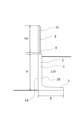
次に、図16に示す、逆L型コンクリート擁壁1として使用する場合、即ち、たて壁2の前面2Aにて土砂の土圧を受ける場合、底版3上に所定の根入れ深さDFの土砂を盛る必要があり、この根入れ深さDFは以下の表1、表2の一例に示す寸法比率とすることが望ましい。
Next, when used as an inverted L-shaped
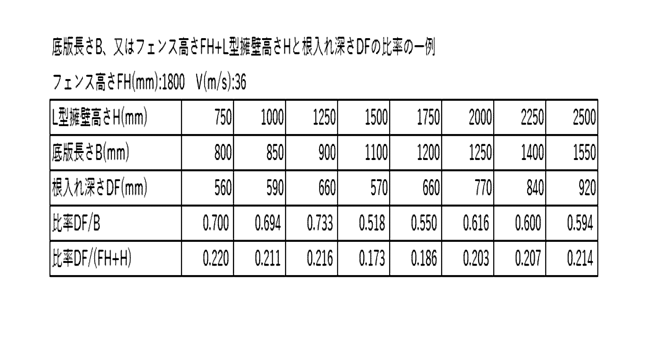

即ち、これら表1、表2を参照すると、底版長さB(mm)に対する根入れ深さDF(mm)の比率DF/Bを0.43以上とすることが望ましく、0.74以上とすることがより望ましい。しかし、0.74より大きい比率であると、L型コンクリート擁壁1の安定設置が可能となる反面、高低差が小さくなってしまう恐れがある。従って、比率DF/Bを0.43~0.74の範囲とすることが最も望ましいものである。
That is, referring to these Tables 1 and 2, it is desirable that the ratio DF/B of the penetration depth DF (mm) to the bottom plate length B (mm) be 0.43 or more, and 0.74 or more. It is more desirable. However, if the ratio is larger than 0.74, the L-shaped
また、フェンス高さFH(mm)+L型擁壁高さH(mm)に対する根入れ深さDF(mm) の比率DF/(FH+H)を0.13以上とすることが望ましく、0.22以上とすることがより望ましい。しかし、0.22より大きい比率であると、L型コンクリート擁壁1の安定設置が可能となる反面、高低差が小さくなってしまう恐れがある。従って、比率DF/Bを0.13~0.22の範囲とすることが最も望ましいものである。
In addition, it is desirable that the ratio DF/(FH+H) of penetration depth DF (mm) to fence height FH (mm) + L-shaped retaining wall height H (mm) be 0.13 or more, and 0.22 or more. It is more desirable to do so. However, if the ratio is larger than 0.22, the L-shaped
底版長さB(mm)に対する根入れ深さDF(mm)の比率DF/B、又はフェンス高さFH(mm)+L型擁壁高さH(mm)に対する根入れ深さDF(mm)の比率DF/(FH+H)を上述した範囲で施工することにより、目隠しフェンス4を備えるL型コンクリート擁壁1であっても、適正な高低差を保った上で、土砂の土圧や強風に影響されにくい安定した設置が可能となるものである。
Ratio DF/B of penetration depth DF (mm) to bottom slab length B (mm), or penetration depth DF (mm) to fence height FH (mm) + L-shaped retaining wall height H (mm) By constructing the ratio DF/(FH+H) within the above-mentioned range, even if it is an L-shaped
このようにL型コンクリート擁壁1を設置した後、目隠しフェンス4の支柱8を支柱用穴9に挿入して隙間にモルタルを流し込んで固める。ここで、風の影響を受けるフェンスのフェンス高さFHと支柱埋め込み深さDとの関係について表3を参照して説明する。尚、本実施例のフェンス幅FWは約2000mmとする。
After installing the L-shaped

次いで、支柱用穴9を長くした角丸長方形状の実施例2について、図17乃至図20を参照して説明する。
Next, a second embodiment having a rectangular shape with rounded corners in which the
図19、20に示す如く、L型コンクリート擁壁1を敷地のコーナー部に設置する場合は、図18に示す如く、突き合わされるL型コンクリート擁壁1の端部14を切断線で切除し、この端部14を切除したL型コンクリート擁壁1同士の切断面を向かい合わせて接続する。
As shown in Figures 19 and 20, when installing the L-shaped
ここで、図17に示す如く、支柱用穴9は長辺が短辺の2倍以上の長さを有する角丸長方形状であるため、例えば、コーナー部に配置されるL型コンクリート擁壁1で、コーナー部の角度に合わせて支柱用穴9を含む端部を切断しなければならない場合であっても、支柱用穴9は十分に余裕のある長さに形成されているため、切断後でも支柱8が挿入できるだけの穴9の大きさを確保できる。
Here, as shown in FIG. 17, the
例えば、コンクリート擁壁1同士で形成される角度が直角である場合、2つのコンクリート擁壁1の端部14を斜め45度に切断して、この45度に切断した面同士を突き合わせることにより直角にしている。この際、支柱用穴9の一部も切り取られてしまうことになるが、支柱用穴9は長辺が短辺の2倍以上の長さを有しているため、支柱用穴9の一部が切除されても支柱8を挿入できるだけの大きさの穴が残り、別途穴を開け直す必要はない。
For example, if the angle formed by the
次いで、たて壁2の上側板厚T1と、たて壁2表面と支柱用穴9との間の板厚tとの関係について、図21を参照して実施例3を説明する。
Next, Example 3 will be described with reference to FIG. 21 regarding the relationship between the upper plate thickness T1 of the
通常、前記たて壁2の上側板厚T1は180mm~300mm程度である。図21に示す前記たて壁2の前面2A、背面2B、側面2D側の表面と、前記支柱用穴9との間の板厚tが薄いと、強風によるフェンス支柱8への過剰な負荷により、支柱用穴9周辺にひび割れ、欠け等の破損が生じる恐れがある。
Usually, the upper plate thickness T1 of the
このため、前記たて壁2の前面2A、背面2B、側面2D側の表面と、前記支柱用穴9との間の板厚tを、たて壁2の上側板厚T1の1/3~1/10としている。これにより、板厚tは十分な厚み(例えば30mm)を確保することができることとなるため、フェンス4が強風を受けて支柱8に負荷がかかっても、支柱用穴9周辺にひび割れ、欠け等の破損が発生してしまうことを極力防止できるものである。
Therefore, the plate thickness t between the
以上詳述した如く、本発明にかかるコンクリート擁壁1は、天面2Cにフェンス4等の支柱8が挿入される支柱用穴9が形成され、鉛直方向に延在するとともに、前面2Aと背面2Bの厚さが一定の矩形状をなすたて壁2と、このたて壁2の背面2Bの下端から水平方向に延在する底版3とを、コンクリートにてL型に一体成形し、
As described in detail above, the
たて壁2の背面2Bにて底版3上の土砂の土圧を受ける態様のL型コンクリート擁壁1の施工と、たて壁2の前面2Aにて土砂の土圧を受けると共に、所定の根入れ深さDFを有する態様の逆L型コンクリート擁壁1の施工と、のいずれの態様であっても使用することが可能であって、前記たて壁2の前面2A及び背面2Bの両側のコンクリート内に、正面視で全面に配置された前面側鉄筋10A及び背面側鉄筋10Bを備えているため、
Construction of an L-shaped
たて壁2の背面2B側であって底版3上の土砂は、たて壁背面2B側の背面側鉄筋10Bにて土圧を受け、たて壁2の前面2A側の土砂は、たて壁正面2A側の前面側鉄筋10Aにて土圧を受けるものである。即ち、L型コンクリート擁壁、逆L型コンクリート擁壁いずれの態様の施工であっても、土砂の土圧によるたて壁2の損傷を極力防止できる。
The earth and sand on the
また、たて壁2の前面2Aにて土砂の土圧を受ける態様の施工の場合、所定深さの根入れDFを行うことにより、風の影響を受けやすいフェンス4等を設置したコンクリート擁壁1であっても、土砂の土圧や強風によってコンクリート擁壁1が滑動しまうことを極力防止することができる。
In addition, in the case of construction in which the
本発明にかかるコンクリート擁壁1では、フェンス4等の支柱8が横断面角形状または丸形状のいずれの形状であっても挿入可能な角丸長方形状の支柱用穴9を備えたているため、支柱用穴9の開け直しなどを不要とし、フェンス4の設置作業の作業性向上を図ることができる。
The
本発明にかかるコンクリート擁壁1では、前記支柱用穴9の底部と連通するとともに、たて壁側面2Dに開口する排水孔13を形成している。このため、コンクリート擁壁1を屋外で保管する場合でも、支柱用穴9に流れ込んだ雨水を排水孔13で排水することができ、冬場などに溜まった雨水が氷結して支柱用穴9を破損してしまうことを防止できる。
In the
本発明にかかるコンクリート擁壁1では、前記たて壁2の前面2A側表面と前記支柱用穴9との間の板厚t、及び背面2B側表面と前記支柱用穴9との間の板厚t、更には側面2D側表面と前記支柱用穴9との間の板厚tを、たて壁の板厚T1の1/3~1/10としている。このため、フェンス4が強風を受けて支柱8に負荷がかかっても支柱用穴9周辺にひび割れ、欠け等の破損が発生してしまうことを極力防止できる。
In the
本発明にかかるコンクリート擁壁1の施工方法は、前記たて壁2の前面2Aにて土砂の土圧を受ける態様の施工の場合、前記底版3の延在方向の長さBに対する根入れ深さDFの比率DF/Bを0.43以上とすることで、土砂の土圧や強風によるコンクリート擁壁1の滑動を極力防止できる。
In the construction method of the
本発明にかかるコンクリート擁壁1の施工方法は、前記たて壁2の前面2Aにて土砂の土圧を受ける態様の施工の場合、たて壁の高さHとフェンス高さFHとを加算した寸法に対する根入れ深さDFの比率DF/(FH+H)を0.13以上とすることで、土砂の土圧や強風によるコンクリート擁壁1の滑動を極力防止できる。
In the construction method of the
本発明にかかるコンクリート擁壁1の施工方法は、前記たて壁2の支柱用穴9を囲うようにコンクリート内に支柱穴鉄筋12を備えることで、強風により支柱用穴9周辺にひび割れ、欠け等の破損が発生してしまうことを極力防止できる。
The construction method of the
また、前記フェンス4の高さFHに対する支柱8の埋め込み深さDの比率D/FHを0.17以上とすることで、強風により支柱8が抜けてフェンス4が脱落してしまうことを極力防止できる。
In addition, by setting the ratio D/FH of the embedded depth D of the
1 L型コンクリート擁壁
2 たて壁
2A 前面
2B 背面
2C 天面
2D 側面
3 底版
3A 上面
3B 下面
4 フェンス
5 ハンチ
6 水抜孔
7 施工用アンカー
8 支柱
9 支柱用穴
10A 前面側鉄筋
10B 背面側鉄筋
11A 上面側鉄筋
11B 下面側鉄筋
12 支柱穴鉄筋
13 排水孔
14 端部
15 パネル
16 板状接続金具
17 固定具
T1 上側板厚
T2 下側板厚
H たて壁の高さ
FH フェンスの高さ
DF 根入れ深さ
D 支柱の埋め込み深さ
B 底版の長さ
W コンクリート擁壁の幅
FW フェンス幅
1 L-shaped
Claims (5)
前記たて壁の前面側表面と前記支柱用穴との間の板厚、及び背面側表面と前記支柱用穴との間の板厚を、たて壁の板厚の1/3~1/10とするとともに、支柱用穴を囲うようにコンクリート内に支柱穴鉄筋を配置し、
前記支柱用穴の底部と連通するとともに、たて壁側面に開口する排水孔を形成し、
たて壁の背面にて底版上の土砂の土圧を受ける態様の施工と、
たて壁の前面にて土砂の土圧を受けると共に、所定の根入れ深さを有する態様の施工と、
のいずれの態様であっても使用することが可能であって、
前記たて壁の前面及び背面の両側のコンクリート内に正面視で全面に配置され、上下方向に延在する主筋と、この主筋を拘束する帯筋とよりなる鉄筋を備えたことを特徴とするコンクリート擁壁。 A vertical wall having a rectangular shape with a vertically extending hole having a pillar hole into which a fence or other pillar is inserted, and having a constant thickness on the front and back sides, and the back side of the vertical wall. A bottom plate extending horizontally from the lower end is integrally formed into an L-shape with concrete,
The thickness between the front surface of the vertical wall and the support hole, and the thickness between the back surface and the support hole, are set to 1/3 to 1/3 of the thickness of the vertical wall. 10, and place the post hole reinforcing bars in the concrete to surround the post holes,
forming a drainage hole that communicates with the bottom of the support hole and opens on the side surface of the vertical wall;
Construction in such a way that the back of the vertical wall receives the earth pressure of the earth and sand on the bottom slab,
Construction in a manner that receives soil pressure from earth and sand in front of the vertical wall and has a predetermined penetration depth;
It is possible to use any aspect of
It is characterized by comprising reinforcing bars that are arranged in the concrete on both sides of the front and back sides of the vertical wall as seen from the front, and are made up of main reinforcing bars that extend in the vertical direction and tie bars that restrain the main reinforcing bars. Concrete retaining wall.
前記たて壁の前面側表面と前記支柱用穴との間の板厚、及び背面側表面と前記支柱用穴との間の板厚を、たて壁の板厚の1/3~1/10とするとともに、支柱用穴を囲うようにコンクリート内に支柱穴鉄筋を配置し、
前記支柱用穴の底部と連通するとともに、たて壁側面に開口する排水孔を形成し、
たて壁の背面にて底版上の土砂の土圧を受ける態様の施工と、
たて壁の前面にて土砂の土圧を受けると共に、所定の根入れ深さを有する態様の施工と、
のいずれの態様であっても使用することが可能であって、
前記たて壁の前面及び背面の両側のコンクリート内に、正面視で全面に配置され、上下方向に延在する主筋と、この主筋を拘束する帯筋とよりなる鉄筋を備え、
前記たて壁の前面にて土砂の土圧を受ける態様の施工の場合、前記底版の延在方向の長さBに対する根入れ深さDFの比率DF/Bを0.43以上としたことを特徴とするコンクリート擁壁の施工方法。 A vertical wall having a rectangular shape with a vertically extending hole having a pillar hole into which a fence or other pillar is inserted, and having a constant thickness on the front and back sides, and the back side of the vertical wall. A bottom plate extending horizontally from the lower end is integrally formed into an L-shape with concrete,
The thickness between the front surface of the vertical wall and the support hole, and the thickness between the back surface and the support hole, are set to 1/3 to 1/3 of the thickness of the vertical wall. 10, and place the post hole reinforcing bars in the concrete to surround the post holes,
forming a drainage hole that communicates with the bottom of the support hole and opens on the side surface of the vertical wall;
Construction in such a way that the back of the vertical wall receives the earth pressure of the earth and sand on the bottom slab,
Construction in a manner that receives soil pressure from earth and sand in front of the vertical wall and has a predetermined penetration depth;
It is possible to use any aspect of
In the concrete on both sides of the front and back sides of the vertical wall, reinforcing bars are provided, which are arranged on the entire surface when viewed from the front, and are composed of main reinforcing bars extending in the vertical direction and tie bars that restrain the main reinforcing bars ,
In the case of construction where the front side of the vertical wall receives earth pressure from earth and sand, the ratio DF/B of the penetration depth DF to the length B in the extending direction of the bottom slab is 0.43 or more. A distinctive method of constructing concrete retaining walls.
前記たて壁上に、たて壁とほぼ同じ幅であって、且つ所定高さFHの目隠しフェンスを設置し、
前記たて壁の前面側表面と前記支柱用穴との間の板厚、及び背面側表面と前記支柱用穴との間の板厚を、たて壁の板厚の1/3~1/10とするとともに、支柱用穴を囲うようにコンクリート内に支柱穴鉄筋を配置し、
前記支柱用穴の底部と連通するとともに、たて壁側面に開口する排水孔を形成し、
たて壁の背面にて底版上の土砂の土圧を受ける態様の施工と、
たて壁の前面にて土砂の土圧を受けると共に、所定の根入れ深さを有する態様の施工と、
のいずれの態様であっても使用することが可能であって、
前記たて壁の前面及び背面の両側のコンクリート内に正面視で全面に配置され、上下方向に延在する主筋と、この主筋を拘束する帯筋とよりなる鉄筋を備え、
前記たて壁の前面にて土砂の土圧を受ける態様の施工の場合、たて壁の高さHとフェンス高さFHとを加算した寸法に対する根入れ深さDFの比率DF/(FH+H)を0.13以上としたことを特徴とするコンクリート擁壁の施工方法。 A vertical wall has a post hole formed in the top surface into which a fence post is inserted, extends vertically, and has a rectangular shape with a constant thickness on the front and back sides, and a vertical wall on the back side of the vertical wall. The bottom plate extending horizontally from the lower end is integrally molded into an L-shape with concrete,
Installing a blind fence on the vertical wall, which has approximately the same width as the vertical wall and has a predetermined height FH,
The thickness between the front surface of the vertical wall and the support hole, and the thickness between the back surface and the support hole, are set to 1/3 to 1/3 of the thickness of the vertical wall. 10, and place the post hole reinforcing bars in the concrete to surround the post holes,
forming a drainage hole that communicates with the bottom of the support hole and opens on the side surface of the vertical wall;
Construction in such a way that the back of the vertical wall receives the earth pressure of the earth and sand on the bottom slab,
Construction in a manner that receives soil pressure from earth and sand in front of the vertical wall and has a predetermined penetration depth;
It is possible to use any aspect of
Reinforcing bars are arranged entirely in the concrete on both sides of the front and back sides of the vertical wall when viewed from the front, and include a main reinforcing bar extending in the vertical direction, and a reinforcing bar that restrains the main reinforcing bar ,
In the case of construction in which the front surface of the vertical wall receives earth pressure from earth and sand, the ratio of the penetration depth DF to the sum of the height H of the vertical wall and the fence height FH is DF/(FH+H). A method for constructing a concrete retaining wall, characterized in that the ratio is 0.13 or more.
前記たて壁上に、たて壁とほぼ同じ幅であって、且つ所定高さFHの目隠しフェンスを設置し、
前記たて壁の前面側表面と前記支柱用穴との間の板厚、及び背面側表面と前記支柱用穴との間の板厚を、たて壁の板厚の1/3~1/10とするとともに、支柱用穴を囲うようにコンクリート内に支柱穴鉄筋を配置し、
前記支柱用穴の底部と連通するとともに、たて壁側面に開口する排水孔を形成し、
たて壁の背面にて底版上の土砂の土圧を受ける態様の施工と、
たて壁の前面にて土砂の土圧を受けると共に、所定の根入れ深さを有する態様の施工と、
のいずれの態様であっても使用することが可能であって、
前記たて壁の前面及び背面の両側のコンクリート内に、正面視で全面に配置され、上下方向に延在する主筋と、この主筋を拘束する帯筋とよりなる鉄筋を備え、
前記フェンスの高さFHに対する支柱の埋め込み深さDの比率D/FHを0.17以上としたことを特徴とするコンクリート擁壁の施工方法。 A vertical wall has a post hole formed in the top surface into which a fence post is inserted, extends vertically, and has a rectangular shape with a constant thickness on the front and back sides, and a vertical wall on the back side of the vertical wall. The bottom plate extending horizontally from the lower end is integrally molded into an L-shape with concrete,
Installing a blind fence on the vertical wall, which has approximately the same width as the vertical wall and has a predetermined height FH,
The thickness between the front surface of the vertical wall and the support hole, and the thickness between the back surface and the support hole, are set to 1/3 to 1/3 of the thickness of the vertical wall. 10, and place the post hole reinforcing bars in the concrete to surround the post holes,
forming a drainage hole that communicates with the bottom of the support hole and opens on the side surface of the vertical wall;
Construction in such a way that the back of the vertical wall receives the earth pressure of the earth and sand on the bottom slab,
Construction in a manner that receives soil pressure from earth and sand in front of the vertical wall and has a predetermined penetration depth;
It is possible to use any aspect of
In the concrete on both sides of the front and back sides of the vertical wall, reinforcing bars are provided, which are arranged on the entire surface when viewed from the front, and are composed of main reinforcing bars extending in the vertical direction and tie bars that restrain the main reinforcing bars ,
A method for constructing a concrete retaining wall, characterized in that the ratio D/FH of the embedding depth D of the pillar to the height FH of the fence is 0.17 or more.
Priority Applications (1)
| Application Number | Priority Date | Filing Date | Title |
|---|---|---|---|
| JP2023069689A JP7425516B1 (en) | 2023-04-21 | 2023-04-21 | Concrete retaining wall and concrete retaining wall construction method |
Applications Claiming Priority (1)
| Application Number | Priority Date | Filing Date | Title |
|---|---|---|---|
| JP2023069689A JP7425516B1 (en) | 2023-04-21 | 2023-04-21 | Concrete retaining wall and concrete retaining wall construction method |
Publications (2)
| Publication Number | Publication Date |
|---|---|
| JP7425516B1 true JP7425516B1 (en) | 2024-01-31 |
| JP2024155206A JP2024155206A (en) | 2024-10-31 |
Family
ID=89718042
Family Applications (1)
| Application Number | Title | Priority Date | Filing Date |
|---|---|---|---|
| JP2023069689A Active JP7425516B1 (en) | 2023-04-21 | 2023-04-21 | Concrete retaining wall and concrete retaining wall construction method |
Country Status (1)
| Country | Link |
|---|---|
| JP (1) | JP7425516B1 (en) |
Citations (2)
| Publication number | Priority date | Publication date | Assignee | Title |
|---|---|---|---|---|
| JP4081482B2 (en) | 2005-09-14 | 2008-04-23 | 有限会社インパクト | Free-standing concrete retaining wall structure |
| JP6384768B2 (en) | 2017-06-19 | 2018-09-05 | 平成テクノス株式会社 | Precast concrete product with displacement recovery structure |
-
2023
- 2023-04-21 JP JP2023069689A patent/JP7425516B1/en active Active
Patent Citations (2)
| Publication number | Priority date | Publication date | Assignee | Title |
|---|---|---|---|---|
| JP4081482B2 (en) | 2005-09-14 | 2008-04-23 | 有限会社インパクト | Free-standing concrete retaining wall structure |
| JP6384768B2 (en) | 2017-06-19 | 2018-09-05 | 平成テクノス株式会社 | Precast concrete product with displacement recovery structure |
Also Published As
| Publication number | Publication date |
|---|---|
| JP2024155206A (en) | 2024-10-31 |
Similar Documents
| Publication | Publication Date | Title |
|---|---|---|
| US6920728B2 (en) | Column and beam construction and method | |
| US20140020317A1 (en) | Modular Wall System with Footing Form II | |
| US11661719B2 (en) | Building elements for making retaining walls, and systems and methods of using same | |
| KR101084615B1 (en) | Shelf retaining wall structure using PC wall board and construction method | |
| US20130008125A1 (en) | Construction method for new underground structure | |
| KR101140378B1 (en) | Reinforcement | |
| US20030033773A1 (en) | Foundation construction | |
| KR101289155B1 (en) | Eco-friendly rainwater storage bath | |
| US20160362890A1 (en) | Precast concrete wall member and method of erecting the same | |
| JP7425516B1 (en) | Concrete retaining wall and concrete retaining wall construction method | |
| KR101929459B1 (en) | precast construction having double side pannel structure | |
| US4293245A (en) | Structural system and structural elements for use and construction of earth filled walls | |
| JP2004084184A (en) | Precast continuous foundation for guard fence | |
| JP3242476U (en) | concrete retaining wall | |
| JP4834649B2 (en) | Construction structure of embankment structure, retaining wall block for construction of embankment structure and construction method of embankment structure | |
| US20250277364A1 (en) | Formwork for retaining walls | |
| JP7653708B2 (en) | Bridges | |
| KR200424468Y1 (en) | Soil Nailing Set Lattice Prefab Retaining Wall | |
| CA2522665C (en) | Modular wall system with footing form | |
| KR100793684B1 (en) | Prefabricated vertical wall structure and construction method | |
| JPH0352822Y2 (en) | ||
| JP4077378B2 (en) | Block fence construction method and reinforcing bracket for block fence | |
| KR101954113B1 (en) | Retaining wall structure and construction method thereof | |
| JP2025047874A (en) | Concrete block wall structure | |
| KR20020009116A (en) | Precast concrete segment for arch type culvert and construction method using this segment |
Legal Events
| Date | Code | Title | Description |
|---|---|---|---|
| A621 | Written request for application examination |
Free format text: JAPANESE INTERMEDIATE CODE: A621 Effective date: 20230425 |
|
| A131 | Notification of reasons for refusal |
Free format text: JAPANESE INTERMEDIATE CODE: A131 Effective date: 20231107 |
|
| A521 | Request for written amendment filed |
Free format text: JAPANESE INTERMEDIATE CODE: A523 Effective date: 20231129 |
|
| TRDD | Decision of grant or rejection written | ||
| A01 | Written decision to grant a patent or to grant a registration (utility model) |
Free format text: JAPANESE INTERMEDIATE CODE: A01 Effective date: 20240109 |
|
| A61 | First payment of annual fees (during grant procedure) |
Free format text: JAPANESE INTERMEDIATE CODE: A61 Effective date: 20240112 |
|
| R150 | Certificate of patent or registration of utility model |
Ref document number: 7425516 Country of ref document: JP Free format text: JAPANESE INTERMEDIATE CODE: R150 |